

Page 1

ALLNIC AUDIO
A-2500
211/845 SINGLE-ENDED TRIODE
MONOBLOCK POWER AMPLIFIERS
OWNER’S MANUAL
Page 2

2
ALLNIC AUDIO
A-2500
211/845 SINGLE-ENDED TRIODE (SET)
MONOBLOCK POWER AMPLIFIERS
Thank you for purchasing the Allnic Audio A-2500 SET Monoblock Power
Amplifiers. We are certain your trust in Allnic Audio and its dealers
worldwide, as well as your appreciation for the sound of this high-quality
device, will be rewarded by its excellent operation for years to come.
Please read this entire manual before you connect the A-2500 SET
Monoblocks to the other components of your system and the wall outlet.
*** Information and specifications for the Allnic Audio product
described in this manual are subject to change without notice.
*** For a list of Allnic Audio distributers around the world, please visit
Allnic Audio’s website:
http://allnicaudio.com
Page 3

3
TABLE OF CONTENTS:
INTRODUCING THE A-2500 211/845
SINGLE-ENDED TRIODE
MONOBLOCK POWER AMPLIFIERS
4
WHAT’S IN THE BOX?
5
SAFETY
5
CLEANING
Chassis
Connectors
6
INITIAL SET-UP
Location, Location, Location
Inputs
Speaker Terminals
Power Connection
6
INITIAL POWER ON
8
OPERATION
8
TUBES AND TUBE BIAS
8
SPECIFICATIONS
10
WARRANTY
10
FIGURES
11
Please read about SAFETY before you attempt to use the A-2500s - we
care about our customers and the equipment, and we want you to enjoy
this product for a long time!
Page 4

4
INTRODUCING THE A-2500 211/845 SINGLE-ENDED TRIODE MONOBLOCK POWER AMPLIFIERS
The A-2500 is Allnic Audio’s most powerful, power tube flexible, single-ended monoblock power
amplifier model. Like all Allnic Audio products, the A-2500s have Permalloy (iron and nickel alloy) for
their transformer cores. Allnic is grateful to Mr. G.W. Elmen of Western Electric for inventing
Permalloy for transformer core use, and in so doing, providing an enormous service to recorded
music listeners everywhere.
The A-2500s use the superbly musical 211 or 845 (customer’s choice on ordering) power tubes in
single-ended configuration to provide the special musicality of the 211/845 tubes. The A-2500s have
the following features:
• The A-2500s are single-ended triode monoblock power amplifiers. Each monoblock provides 20 watts of
pure Class A, continuous power with either the 211 or 845 tube.
• Powerful Driving Circuitry. Allnic believes in the importance of using high-quality, low noise and
powerful driving circuitry in all its amplifying devices. Off-the-shelf design is not a part of the magic of
these amplifiers. Tubes and transformer characteristics are closely matched to complement each other
to achieve the most accurate and satisfying sound. In the A-2500s, we employ a new old stock (NOS)
6CM7 (for the 211 power tube) and a 6DR7 (for the 845 power tube) triode as the input tube for the
choke-transformer driving circuit. The listener can easily hear and even "feel" the differences between
these designs and other, more conventional ones. Please imagine, as you listen to the A-2500s, its sound
compared to the sound of an amplifier using conventional, for example, 6SN7, 6922, 12AU7 or 12BH7s.
• Fixed bias of both the 211 and 845 tubes for more power and less distortion.
• Direct-heated Vacuum Tube Rectification. The A-2500s use a 5R4 full-wave rectifier tube rather than a
semiconductor diode in the rectification circuit. This provides both sonic benefits and improved
protection for the 211/845 power tubes.
• Point-to-point hard-wired circuitry.
• “Full Engagement" Output Transformers. Conventional output transformers use pre-set secondary
windings to accommodate 4, 8 and 16 ohm loudspeaker loads. However, these conventional
transformers utilize only one secondary winding at a time, while the other secondary windings remain
"idle". This approach has two adverse effects. First, the output transformers are not working at their
maximum efficiency, reducing their output relative to their potential. Second, the "idle" windings are
not actually "idle"; they are subject to parasitic oscillations, producing their own "signal". This
undesirable electrical information is additive to the transformer's output, distorting the amplified signal
going to the loudspeaker. Allnic's "Full Engagement" transformers address these issues by having 4
independent, secondary windings that are always fully connected, never "idled". This means that all
secondary windings are always connected to your loudspeakers, regardless of which output switch
position you use (4 ohms or 8 ohms or 8 ohms or 16 ohms, depending on the factory configuration you
Page 5

5
have selected). The result is that there is neither a loss of transformer output efficiency, nor the
introduction into the output signal of distortion from parasitic oscillations of the secondary windings.
• Large Nickel/FeSi Core Output Transformers. As with our other models, Allnic uses very large output
transformers (105 mm) with nickel, mixed with FeSi, cores. This provides for higher inductance with
fewer windings than other designs can provide and results in the great benefit of an extremely wide
range of output frequencies.
• Analogue Power Tube Current Monitors. To provide constant current (bias) monitoring for the power
tubes, Allnic uses an analogue current meter to provide extremely accurate monitoring of the 211/845
tube. The meter makes it exceptionally easy to see the status of the tube at any time and to respond
immediately to any variation in bias by use of the top-mounted bias control screw. The meter offers a
simple, unambiguous indication of the tube's status compared to conventional LED bias monitors.
• As are all Allnic Audio products, the A-2500s are fully RoHS (EU Reduction of Hazardous
Substances regulation) compliant in construction and materials.
WHAT’S IN THE BOX?
Please check that each shipping box contains the following:
• One (1) Allnic A-2500 monoblock power amplifier. NOTE: the A-2500s are mirror imaged.
Each amp should be the mirror image of the other, with the rectifier tubes on the right side on
one and on the left side on the other.
• One (1) 15 amp IEC type power cord
One (1) Owner’s Manual is also provided.
Note:
1) The A-2500s ship with the tubes installed.
2) The A-2500s will work with most 15 amp, IEC type aftermarket power cords. The Allnic ZL-
3000 and ZL-5000 power cables will make an excellent match. Of course, only you can
determine the power cord that works most synergistically with the A-2500s in your system.
3) Be sure the A-2500s are labeled for the AC voltage of your location. If they are not, DO NOT
connect them to your AC outlet. Please contact your Allnic dealer.
We advise that you keep the boxes and other packing materials that your A-2500s came in. It will be
useful if you sell your A-2500s or in the unlikely event you need to ship it for service.
SAFETY
• Remove ALL protective cushioning material (cardboard around the tubes) inside the tube
chimneys before operation. The tube chimneys should contain NOTHING except the tubes
Page 6

6
(It is optional to leave the “O” rings on the small tubes; some prefer the sound with the O
rings on).
• Disconnect the power cord by pulling the plug, not the cable.
• Do not attempt any repairs. Do not remove the unit’s chassis cover without specific
authorization from your Allnic dealer.
• Keep the power cord away from heat sources
• Keep the unit away from liquids – do not allow any liquid to enter the interior of the unit.
CLEANING
A. Chassis and glass
Use only a soft, lint-free cloth, dampened slightly with water only (NO cleaning fluids!), to clean the
faceplate, chassis and tube chimneys of the A-2500s.
B. Connectors
You may use any good quality contact cleaner recommended for such applications to clean the contacts
from time to time, as you deem appropriate.
INITIAL SET-UP
A. LOCATION, LOCATION, LOCATION
Like all audio products using tubes, the Allnic Audio A-2500s need to be placed on a solid stand in a
location that provides good air circulation around, above and below the monoblocks.
• DO NOT cover the tops of the A-2500s.
• DO NOT place the A-2500s on carpet or foam.
• DO NOT subject the A-2500s to knocks and shocks as you move them around. This advice is meant
particularly for those who may want to place the A-2500s on some kind of after-market isolation
feet or similar devices. Dropping one side of the A-2500s, or the whole of a unit may cause damage
and may void the warranty.
• DO NOT place the unit near a strong light or heat source.
• DO NOT place anything heavy on the unit.
• DO NOT allow rubber or vinyl materials to rest on the chassis for long periods of time. This could
discolour the metal.
• DO place the A-2500s on a shelf or stand that is stable and not subject to vibration or sudden
shock.
• DO consider using a high-quality power cord, inter-connects and speaker cables. The A-2500s are
highly sensitive electronic devices designed for neutrality and will output what you put into them.
Allnic’s ZL (Zero Loss) Technology power and interconnect cables will work synergistically with the
A-2500s.
• DO try to place A-2500s away from major sources and potential receivers of RFI and EMI.
Though well shielded, the A-2500s will function best away from large power transformers and
Page 7

7
other sources of such interference and from other equipment that could be susceptible to
such forms/sources of interference.
• When the A-2500s are moved from a cold to a warm environment, allow sufficient time for any
condensation to evaporate before plugging the A-2500s into an AC connection.
• Do not attempt any repairs.
B. INPUTS
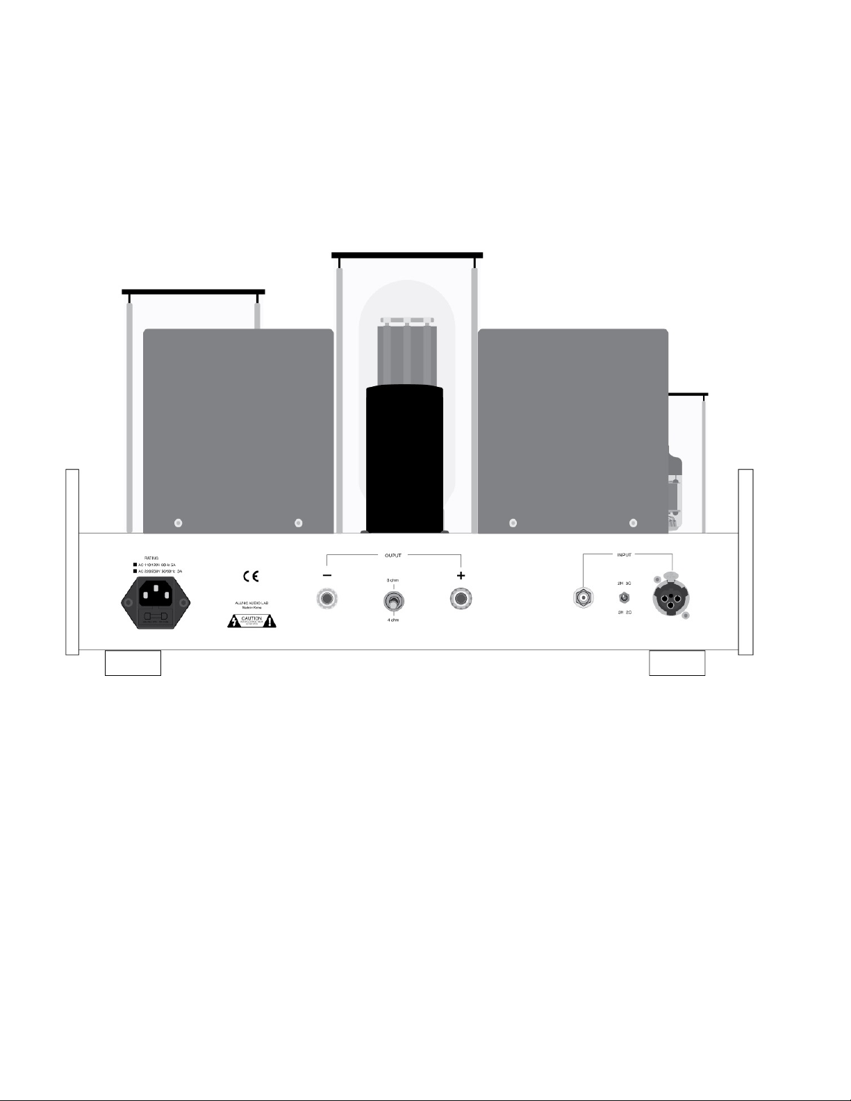
There are two (2) female inputs (See Figure 2). One accepts a balanced cable with a male XLR connector;
the other accepts a cable with a single-ended, RCA type male connector. On one chassis, these input
connections are located on the right (facing the back) rear of the chassis, with the balanced input closest
to the side edge. The inputs are on the left rear of the chassis on the other A-2500. Between the inputs,
there is a switch to select one of two pin configurations for a balanced cable (i.e., it changes the phase).
The top position is for pin 2” hot” and pin 3 “cold”; the bottom position is for the reverse (in both cases,
pin 1 is ground).
C. SPEAKER TERMINALS
Each of the A-2500s is equipped with one pair of high-quality speaker terminals (See Figure 2). These
terminals are located in the middle of the rear panel of each A-2500 chassis, with the red marked terminal
for the live connection labelled positive “+” on the right, and with the return connection labeled negative
“-”, to the left (facing the chassis rear). Between the plus and minus terminals is a switch that provides for
either 8 or 4 ohm impedance, as your speakers may require. The upper position of the switch is for 8 ohm
operation; the lower for 4 ohm operation. 8 and 16 ohm terminals are available by special order. The
terminals accept bare wire (not recommended), spade and banana type connectors.
D. POWER CONNECTION
Connect the input interconnect and speaker cables before you insert the power cable into the
receptacle at the left (facing the back) rear of the chassis on one A-2500, and on the right on the
other (See Figure 2). The A-2500s use a standard 15 amp three prong male IEC connection for AC
input. You need to use power cords with a female 15 amp, three prong IEC connector at one end. The
Allnic ZL-3000 and ZL-5000 power cables will make an excellent match.
The A-2500s you have purchased are set internally for either AC 110/120 volt – 60 HZ, or 220/230 volt –
50 HZ operation. There is no way to change this to another AC setting without return of the A-2500s to
the factory for re-wiring, at the owner’s cost, including transport both directions.
INITIAL POWER-ON
Once you have your A-2500s in place and all connections have been made to your source(s) and
preamplifier, you are ready to turn on the power for your A-2500s. Before you power up the A-2500s,
though, be sure you have:
Page 8

8
•
removed ALL the cushion materials (cardboard) from inside the tube chimneys. (It is optional to
leave the “O” rings on the small tubes; some prefer the sound with the O rings on.)
•
checked that all tubes are snug in their sockets
•
ensured the input connectors that you are using, single ended (RCA) or balanced (XLR), are firm and
secure and if using XLR, that the switch on the back of each chassis is set to the appropriate pin
configuration
•
securely and correctly fastened the speaker cables, ensured that they are also connected properly to
the speakers, and set the speaker impedance switch to match your speakers’ impedance
•
turned on your source(s) and your preamplifier, and turned the preamplifier’s volume control down to
zero or otherwise muted its output
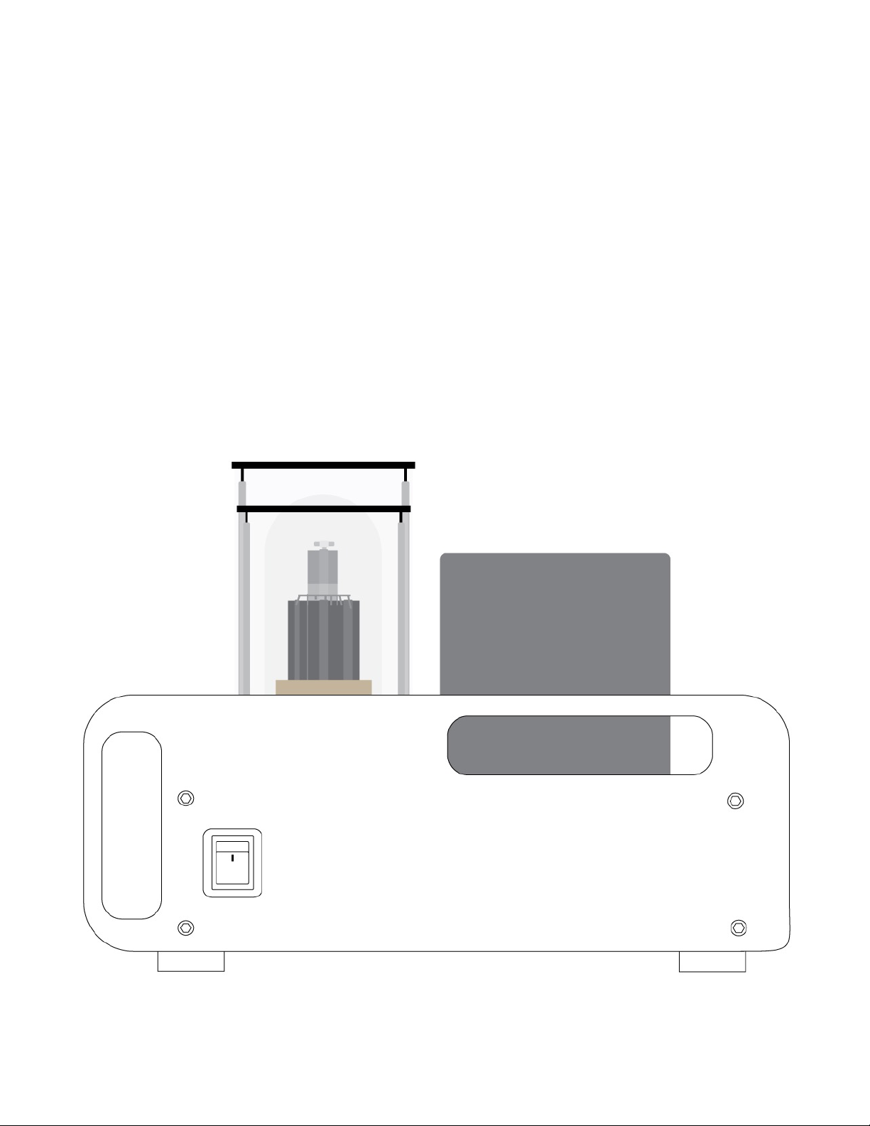
Turn on the A-2500s by depressing the power switch button located (facing the front of the unit) on the
right side-panel (on one chassis and on the left side on the other) to the “on” position (See Figure 1). The
“on” position is with the top of the button switch depressed. Of course, the off position is the reverse.
After about a thirty to forty (30 - 40) second delay (the soft start), the A-2500s will be powered on. After
warm-up and application of full plate voltage, not all tubes may bias at the same rate. Allow one or two
minutes for all the tubes to reach full operating specification.
OPERATION
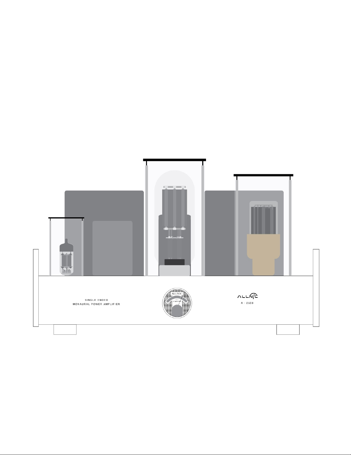
When the power is on, the current meter on the front of the chassis will illuminate (See Figure 3). From
this point on, operation is straight-forward. When you are finished listening, turn off your A-2500
monoblocks first; then, turn off your preamplifier and sources.
In the case of any failure, please contact Your Allnic dealer for assistance.
THE CURRENT METER
The illuminated meter indicates the current supply to the 211/845 power tube in the A-2500. There is a
screw-type potentiometer control on the chassis top in front of each 211/845.
When you turn on the A-2500s, the needle of the current meter should be centred between the two
parallel lines on the meter’s face. Any error of current supply to or failure of a 211/845 tube is indicated by
the needle moving out from between these two parallel lines.
TUBES AND TUBE BIAS
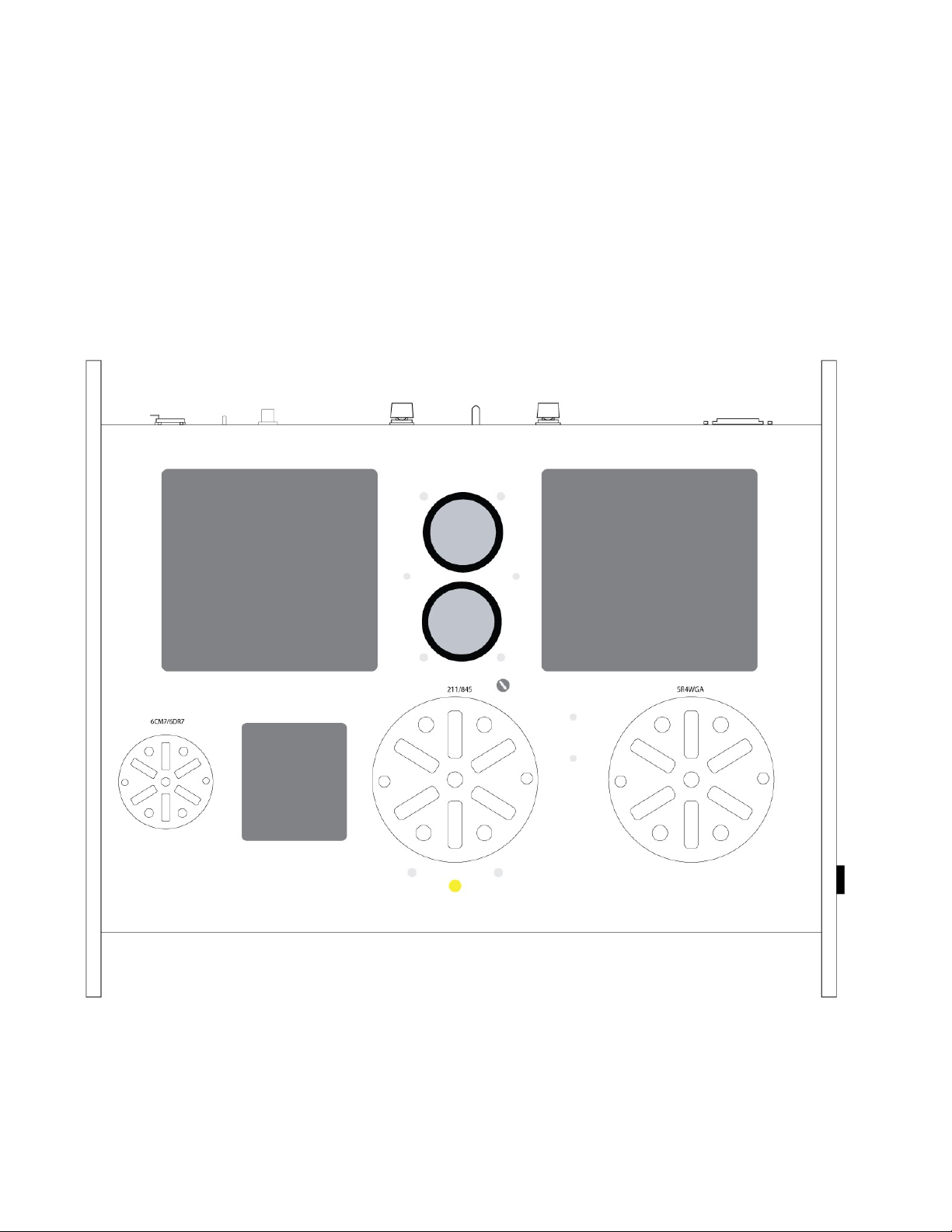
Each A-2500 monoblock uses the following tubes (See Figure 4) TUBES ARE NOT INTERCHANGEABLE
BETWEEN 211/845 VERSIONS (except 5R4 rectifier):
• One (1) x 211 or 845 SET power tube
• One (1) x 6CM7 (211 power tube version)
• One (1) x 6DR7 (845 power tube version)
• One (1) x 5R4 rectifier tube
Page 9

9
To bias the power tube properly by centering the meter’s needle between the meter’s main parallel lines,
use an appropriately bladed screwdriver to adjust the bias control directly in front of the 211/845 by
turning the yellow plastic screw clockwise or counterclockwise. If the needle of a current meter for the
211/845 has moved to the left of the parallel lines on the meter’s face, adjust the bias control by turning
the plastic screw clockwise until the needle has returned to centre between the meter’s parallel lines. If
the meter needle has moved to the right of the parallel lines on the meter face, turn the bias control
counterclockwise to correct.
If the meter’s needle drops to the left limit of the meter’s face during operation, this indicates a failure of
the related 211/845 tube. You must turn off the A-2500 and replace the 211/845 and, probably, the
protection fuse (0.5A, 250V, 20mm slow-blow) for the tube. To replace the fuse, using a screwdriver,
simply turn the top of the fuse cap (located just behind the 211/845 tube – see Figure 4) counterclockwise.
It will spring out holding the fuse. Replace the fuse, push the fuse cap down and turn it clockwise; it will
lock itself. If you have any questions about doing this, please contact your Allnic dealer for assistance.
If the 5.0 Amp AC mains fuse, located at the IEC input, has failed, it can be replaced with the spare fuse
provided in the tray in the IEC mount. Again, if you have any questions about doing this, please contact
your Allnic dealer for assistance.
Of course, you will have to adjust the bias back into the area between the two parallel lines of the meter
for a tube when it is replaced. When replacing a 211/845, first turn the bias control counterclockwise
slightly to reduce current, in case the bias is set too high for the new tube (since the old tube may have
required additional bias). Bring the bias up gradually to the middle between the two lines on the meter.
All consequences of changing or attempting to change tubes are borne by the user unless by express
agreement between the owner and an authorized Allnic representative. Allnic Audio and its authorized
representatives are not liable in any way whatsoever for any injury or loss incurred by the user or for
damage to the A-2500s, any of their parts, or tubes or replacement tubes resulting from the user
changing or attempting to change tubes.
Page 10

10
SPECIFICATIONS FOR THE A-2500 SINGLE-ENDED TRIODE MONOBLOCK POWER AMPLIFIER
• Output Power:
211 or 845: 20 watts
• Total Harmonic Distortion:
0.3% at 5W/1KHz
• Frequency Response:
20Hz - 20KHz, +/- 0.5dB
• S/N Ratio:
-80dB (CCIR, 1KHz)
• Damping Factor:
4 at 8Ω load at 1KHz
• Voltage gain:
+28dB (211 version); +26dB (845 version)
• Input Impedance:
100KΩ (single-ended, unbalanced)
• Input Sensitivity:
0.7V for maximum rated power
• Fuses:
IEC Mains: For 110 – 120V AC regions 5A,
250V, 20mm slow-blow; For 210 – 230V AC
regions: 3A, 250V 20mm slow-blow.
0.5A, 250V, 20mm slow-blow (211/845
protection)
• Tubes (per chassis):
211/845 X 1 (power tube)
6CM7 X 1 for 211 version; 6DR7 X 1 for 845
version (input stage)
5R4 X 1 (rectifier) TUBES ARE NOT
INTERCHANGEABLE BETWEEN 211/845
VERSIONS (except 5R4 rectifier)
• Dimensions:
(W x D x H) 440mm (17.3 inches) x 370mm
(14.6 inches) X 260mm (10.3 inches)
• Weight:
20Kg (44.1 lbs) net per monoblock.
25Kg (55 lbs) shipping weight per monoblock
WARRANTY
FOR WARRANTY SERVICE, PLEASE CONTACT YOUR AUTHORIZED ALLNIC DEALER.
All Allnic Audio amplifier products are warranted against materials and manufacturing defects for parts,
excluding tubes, and labour for two (2) years from date of purchase. Tubes are warranted against
materials and manufacturing defects for one (1) year from date of purchase. The warranty is transferable
Page 11
11
for the balance of the original purchaser’s warranty period, provided, as stated below, no unauthorized
repairs or modifications have been performed on the product. Date of purchase is the date indicated on
the invoice for the product issued by Allnic Audio or its authorized representative. For the warranty to be
valid, a defective product must be returned to Allnic Audio’s authorized representative for service prior to
any unauthorized attempt to repair. Any repair work on an Allnic Audio product not specifically
authorized by Allnic Audio or its authorized representative will void the warranty on the product.
FIGURES
NB. The monoblocks are mirror images of each other.
Figure 1: A-2500 Side View - Switch
Page 12
12
Figure 2: A-2500 – Rear View
Page 13
13
Figure 3: A-2500 – Front View
Page 14
14
Figure 4: A-2500 – Top View
 Loading...