

Page 1
ALL-SG8452M
48-Port Gigabit + 4-SFP Slots
Web Smart Ethernet Switch
User Manual
Page 2

ALL-SG8452M – User Manual
Default-IP:
192.168.2.1
Default Username + Password:
admin
© ALLNET GmbH Computersysteme 2016 - Alle Rechte vorbehalten
Irrtum und Änderungen vorbehalten
2
Page 3

ALL-SG8452M – User Manual
Table of Contents
Chapter 1 Product Introduction ........................................................ 6
1.1 Product Overview ............................................................................... 6
1.2 Features .............................................................................................. 6
1.3 External Component Description ...................................................... 7
1.3.1 Front Panel .................................................................................................. 7
1.3.2 Rear Panel.................................................................................................... 8
1.4 Environment ....................................................................................... 8
1.5 Package Contents ............................................................................... 9
Chapter 2 Installing and Connecting the Switch ........................... 10
2.1 Installation ........................................................................................ 10
2.1.1 Desktop Installation .................................................................................. 10
2.1.2 Rack-mountable Installation in 19-inch Cabinet .................................... 11
2.1.3 Power on the Switch................................................................................. 11
2.2 Connect Computer (NIC) to the Switch ........................................... 12
Chapter 3 How to Login the Switch ................................................ 13
3.1 Switch to End Node .......................................................................... 13
3.2 How to Login the Switch ................................................................. 13
Chapter 4 Switch Configuration ..................................................... 15
4.1 Quickly setting .................................................................................. 15
4.2 PORT ............................................................................................... 18
4.2.1 Basic config ............................................................................................. 18
4.2.2 Port aggregation .................................................................................... 20
4.2.3 Port mirroring ......................................................................................... 21
4.2.4 Port rate-limit ...................................................................................... 22
4.2.5 Storm control .......................................................................................... 23
4.2.6 Port isolation .......................................................................................... 25
4.3 VLAN ............................................................................................... 26
4.3.1 VLAN config ............................................................................................ 26
4.3.2 Trunk-port setting ..................................................................................... 27
4.3.3 Hybrid-port setting ................................................................................... 29
4.4 Fault/Safety ....................................................................................... 30
4.4.1 Anti attack ................................................................................................. 30
4.4.1.1 Anti DHCP attack .............................................................................................. 30
4.4.1.2 Anti DOS ............................................................................................................ 33
4.4.1.3 IPsource guard .................................................................................................. 34
4.4.1.4 Anti three bind ................................................................................................. 35
4.4.2 Channel detection .................................................................................... 36
© ALLNET GmbH Computersysteme 2016 - Alle Rechte vorbehalten
Irrtum und Änderungen vorbehalten
3
Page 4

ALL-SG8452M – User Manual
4.4.2.1 Ping testing ....................................................................................................... 36
4.4.2.2 Tracert testing ................................................................................................... 37
4.4.2.3 Cable testing ..................................................................................................... 38
4.4.3 ACL .......................................................................................................... 39
4.5 MSTP ............................................................................................... 41
4.5.1 MSTP region .............................................................................................. 41
4.5.2 MSTP bridge .............................................................................................. 42
4.6 DHCP relay ........................................................................................ 45
4.6.1 DHCP relay ................................................................................................. 46
4.6.2 0ption82 .................................................................................................... 47
4.7 DHCP Server ...................................................................................... 48
4.7.1 DHCP Config .............................................................................................. 48
4.8 QoS .................................................................................................... 50
4.8.1 Remark ....................................................................................................... 50
4.8.2 Queue config ............................................................................................ 52
4.8.3 Mapping the queue .................................................................................. 53
4.8.3.1 Service class queue mapping ................................................................ 53
4.8.3.2 Differential service class mapping ................................................................... 54
4.8.3.3 Port to service class mapping ........................................................................... 55
4.9 Address table ................................................................................. 56
4.9.1 Mac add and delete .................................................................................. 57
4.9.2 Mac study and laging ............................................................................... 58
4.9.3 Mac address filtering ................................................................................ 59
4.10 Snmp config ................................................................................. 60
4.10.1 Snmp config ............................................................................................ 60
4.10.1.1 Snmp config .................................................................................................... 60
4.10.1.2 Community config .......................................................................................... 61
4.10.1.3 View config ..................................................................................................... 62
4.10.1.4 Group config ................................................................................................... 63
4.10.1.5 User config ...................................................................................................... 64
4.10.1.6 Trap .................................................................................................................. 65
4.10.2 Rmon config ............................................................................................ 66
4.10.2.1 Statistics group................................................................................................ 66
4.10.2.2 History group .................................................................................................. 68
4.10.2.3 Event group .................................................................................................... 69
4.10.2.4 Alarm group .................................................................................................... 70
4.11 LACP ................................................................................................ 71
4.12 SYSTEM ........................................................................................... 74
4.12.1 System config .......................................................................................... 74
4.12.1.1 System settings................................................................................................ 74
4.10.1.2 System restart ................................................................................................. 76
4.10.1.3 Password change ............................................................................................ 77
4.10.1.4 SSH login ......................................................................................................... 78
4.10.1.5 Telnet login................................................................................................... 79
© ALLNET GmbH Computersysteme 2016 - Alle Rechte vorbehalten
Irrtum und Änderungen vorbehalten
4
Page 5

ALL-SG8452M – User Manual
4.10.1.6 System log ....................................................................................................... 79
4.12.2 System upgrade ...................................................................................... 81
4.12.3 Config management .............................................................................. 82
4.12.3.1 Current configuration .................................................................................... 82
4.12.3.2 Configuration backup .................................................................................... 82
4.12.3.3 Restore factory configuration ........................................................................ 83
4.12.4 Config save .............................................................................................. 84
4.12.5 Administrator privileges ......................................................................... 85
4.12.6 Info collect ............................................................................................... 86
Appendix: Technical Specifications ................................................. 88
© ALLNET GmbH Computersysteme 2016 - Alle Rechte vorbehalten
Irrtum und Änderungen vorbehalten
5
Page 6

ALL-SG8452M – User Manual
Chapter 1 Product Introduction
Congratulations for purchasing the Web Smart Ethernet Switch. Before you
install and use this product, please read this manual carefully for full exploiting
the functions of this product.
1.1 Product Overview
This is 48 10/100/1000Mbps RJ45 ports + 4 100/1000Mbps SFP ports Ethernet
Switch. The Switch provides the seamless network connection. This device
integrates 1000Mbps Gigabit Ethernet, 100Mbps Fast Ethernet and 10Mbps
Ethernet network capabilities in a highly flexible package. With
48-10/100/1000Mbps Auto-Negotiation RJ45 ports, all UTP ports support Auto
MDI/MDIX function. The Switch with a low-cost, easy-to-use, high performance
upgrade your old network to a 1000Mbps Gigabit network. It is essential to
helping solve network bottlenecks that frequently develop as more advanced
computer users and newer applications continue to demand greater network
resources.
The Switch is easy to install and use. It is a great selection for office network.
1.2 Features
Comply with IEEE802.3, IEEE802.3u, IEEE802.3ab, IEEE802.3x, IEEE802.3z,
IEEE802.3ad standards
Supports IEEE802.3x flow control for Full-duplex Mode and backpressure for
Half-duplex Mode
Supports MAC address auto-learning and auto-aging
Store and forward mode operates
Support SNMP/RMON/TELENT
Supports IEEE802.1Q VLAN, 4K VLAN Table
Support IEEE802.1p Priority Queues
Support 2K+256-entry ingress and egress ACL
Support Storm Control
Support QoS, Port Mirroring, Link Aggregation Protocol
LED indicators for monitoring power, link/activity ,Speed
Web-based Management Support
Internal power adapter supply
© ALLNET GmbH Computersysteme 2016 - Alle Rechte vorbehalten
Irrtum und Änderungen vorbehalten
6
Page 7
ALL-SG8452M – User Manual
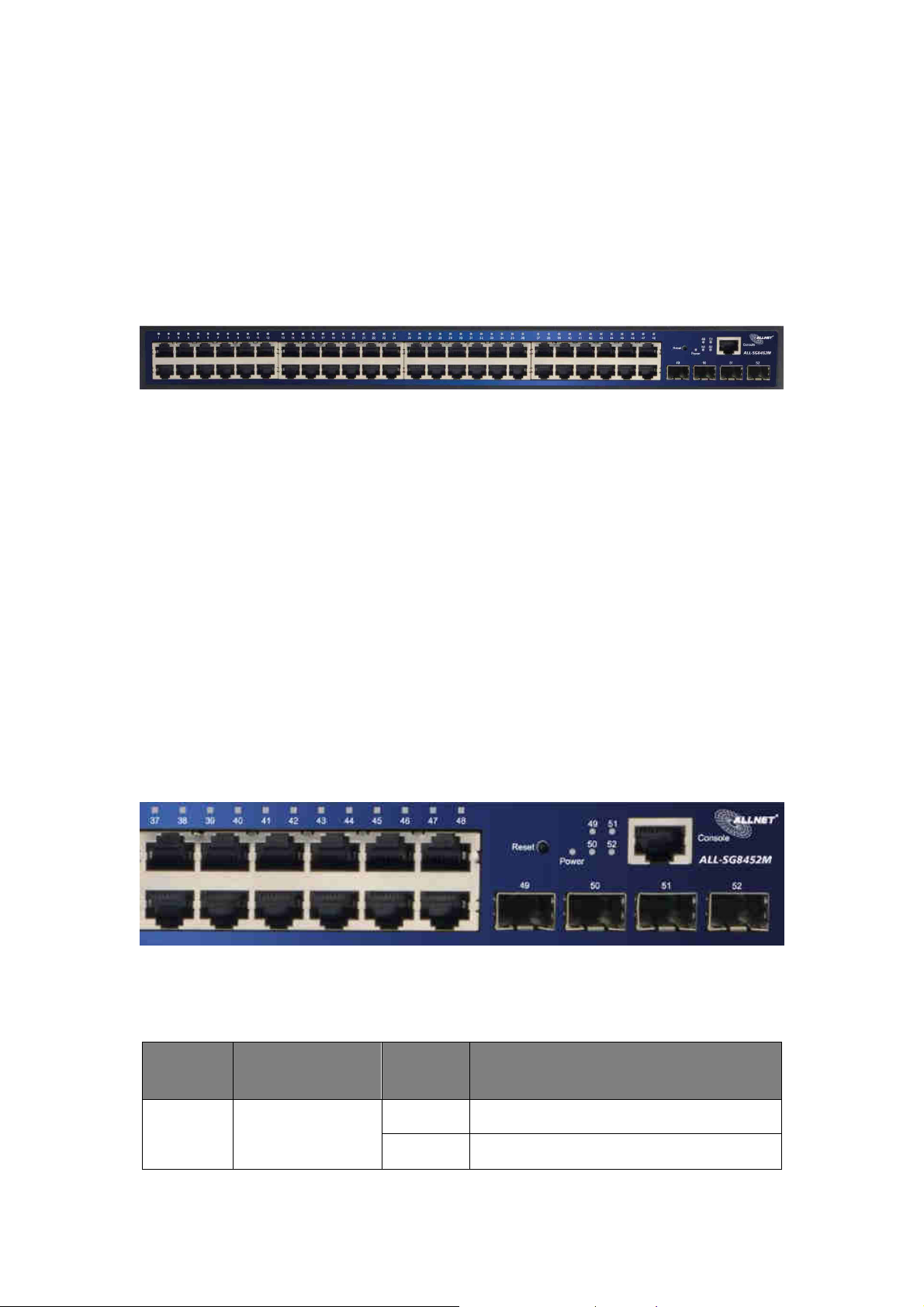
1.3 External Component Description
1.3.1 Front Panel
The front panel of the Switch consists of 48 x 10/100/1000Mbps RJ-45 ports, 4 x
1000Mbps SFP ports, 1 x Console port, 1 x Reset button and a series of LED
indicators as shown as below.
10/100/1000Mbps RJ-45 ports (1~48):
Designed to connect to the device with a bandwidth of 10Mbps, 100Mbps or
1000Mbps. Each has a corresponding 10/100/1000Mbps LED.
SFP ports (49~52):
Designed to install the SFP module and connect to the device with a bandwidth
of 100Mbps or 1000Mbps. Each has a corresponding 100/1000Mbps LED.
Console port (Console):
Designed to connect with the serial port of a computer or terminal for
monitoring and configuring the Switch.
Reset button (Reset):
Keep the device powered on and press down the button for about 6 seconds. The
system restores the factory default settings.
LED indicators:
The LED Indicators will allow you to monitor, diagnose and troubleshoot any
potential problem with the Switch, connection or attached devices.
The following chart shows the LED indicators of the Switch along with
explanation of each indicator.
LED COLOR STATUS
STATUS DESCRIPTION
On Power On
Power Green
Off Power Off
© ALLNET GmbH Computersysteme 2016 - Alle Rechte vorbehalten
Irrtum und Änderungen vorbehalten
7
Page 8
ALL-SG8452M – User Manual
On A device is connected to the port
Off A device is disconnected to the port
LINK/ACT
/Speed
(1~48)
Orange
(10/100Mbps)
Green
(1000Mbps) Flashing Sending or receiving data
On A device is connected to the port
SFP
(49~52)
Green
Off A device is disconnected to the port
Flashing Sending or receiving data
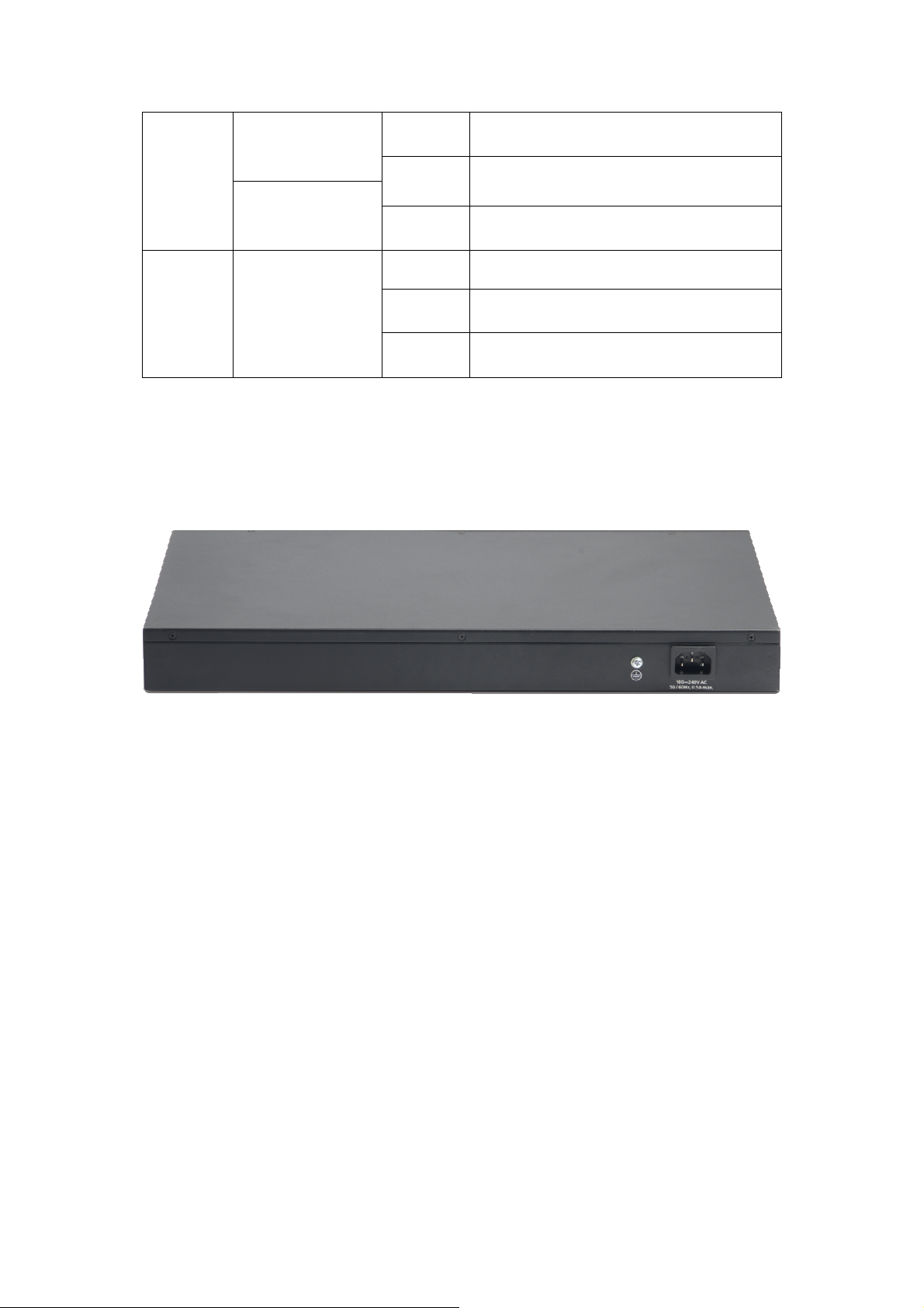
1.3.2 Rear Panel
The rear panel of the Switch contains AC power connector and one marker
shown as below.
AC Power Connector:
Power is supplied through an external AC power adapter. It
supports AC
100-240V, 50/60Hz.
Grounding Terminal:
The Switch already comes with Lightning Protection Mechanism. You can also
ground the Switch through the PE (Protecting Earth) cable of AC cord or with
Ground Cable.
1.4 Environment
Operating Temperature: 0℃~40℃
Storage Temperature: -40℃~70℃
Operating Humidity: 10%~90% non-condensing
Storage humidity: 5%~90% non-condensing
© ALLNET GmbH Computersysteme 2016 - Alle Rechte vorbehalten
Irrtum und Änderungen vorbehalten
8
Page 9

ALL-SG8452M – User Manual
1.5 Package Contents
Before installing the Switch, make sure that the following the "packing list"
listed OK. If any part is lost and damaged, please contact your local agent
immediately. In addition, make sure that you have the tools install Switches and
cables by your hands.
One Web Smart Ethernet Switch
Four rubber feet, two mounting ears and eights screws
One AC power cord
One User Manual
© ALLNET GmbH Computersysteme 2016 - Alle Rechte vorbehalten
Irrtum und Änderungen vorbehalten
9
Page 10
ALL-SG8452M – User Manual
Chapter 2 Installing and Connecting the
Switch
This part describes how to install your Web Smart Ethernet Switch and make
connections to it. Please read the following topics and perform the procedures in
the order being presented.
2.1 Installation
Please follow the following instructions in avoid of incorrect installation causing
device damage and security threat.
Put the Switch on stable place or desktop in case of falling damage.
Make sure the Switch works in the proper AC input range and matches the
voltage labeled on the Switch.
To keep the Switch free from lightning, do not open the Switch’s shell even
in power failure.
Make sure that there is proper heat dissipation from and adequate
ventilation around the Switch.
Make sure the cabinet to enough back up the weight of the Switch and its
accessories.
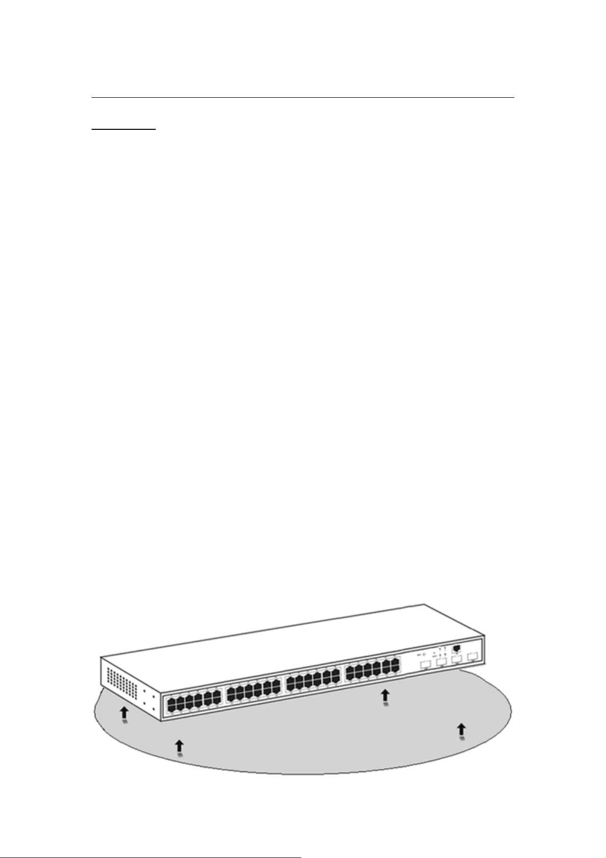
2.1.1 Desktop Installation
Sometimes users are not equipped with the 19-inch standard cabinet. So when
installing the Switch on a desktop, please attach these cushioning rubber feet
provided on the bottom at each corner of the Switch in case of the external
vibration. Allow adequate space for ventilation between the device and the
objects around it.
© ALLNET GmbH Computersysteme 2016 - Alle Rechte vorbehalten
Irrtum und Änderungen vorbehalten
10
Page 11
ALL-SG8452M – User Manual
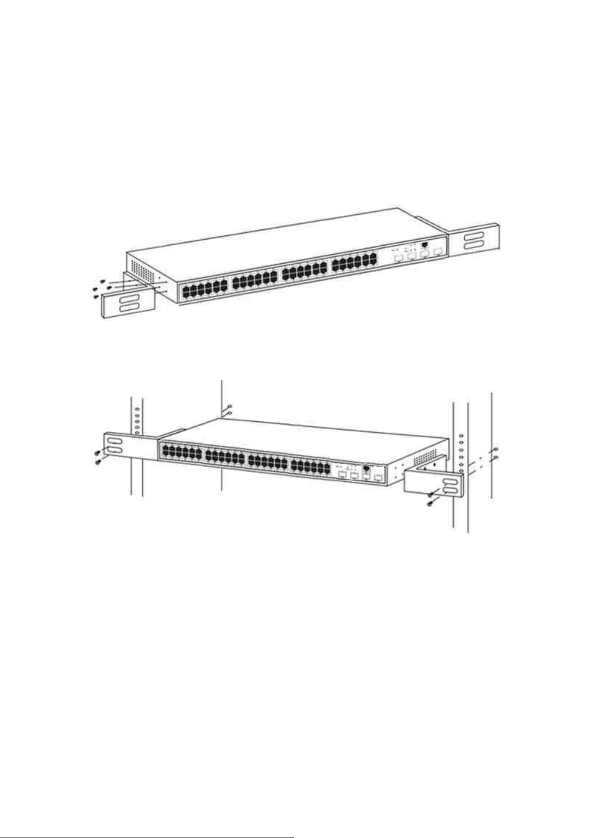
2.1.2 Rack-mountable Installation in 19-inch Cabinet
The Switch can be mounted in an EIA standard-sized, 19-inch rack, which can be
placed in a wiring closet with other equipment. To install the Switch, please
follow these steps:
a. Attach the mounting brackets on the Switch’s side panels (one on each side)
and secure them with the screws provided.
b. Use the screws provided with the equipment rack to mount the Switch on
the rack and tighten it.
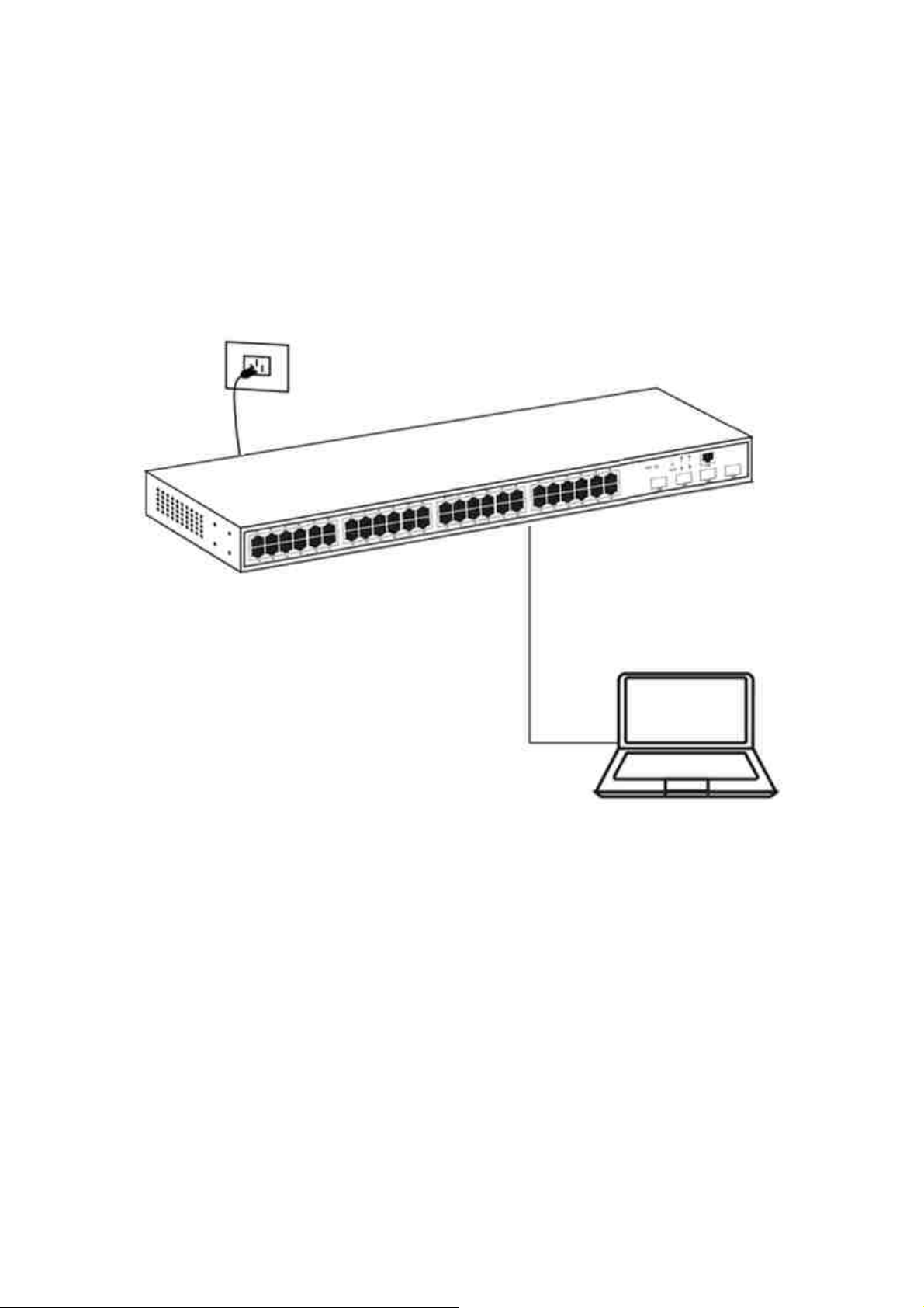
2.1.3 Power on the Switch
The Switch is powered on by the AC 100-240V 50/60Hz internal
high-performance power supply. Please follow the next tips to connect:
AC Electrical Outlet:
It is recommended to use single-phase three-wire receptacle with neutral outlet
or multifunctional computer professional receptacle. Please make sure to
connect the metal ground connector to the grounding source on the outlet.
AC Power Cord Connection:
Connect the AC power connector in the back panel of the Switch to external
receptacle with the included power cord, and check the power indicator is on or
not. When it is on, it indicates the power connection is OK.
© ALLNET GmbH Computersysteme 2016 - Alle Rechte vorbehalten
Irrtum und Änderungen vorbehalten
11
Page 12
ALL-SG8452M – User Manual
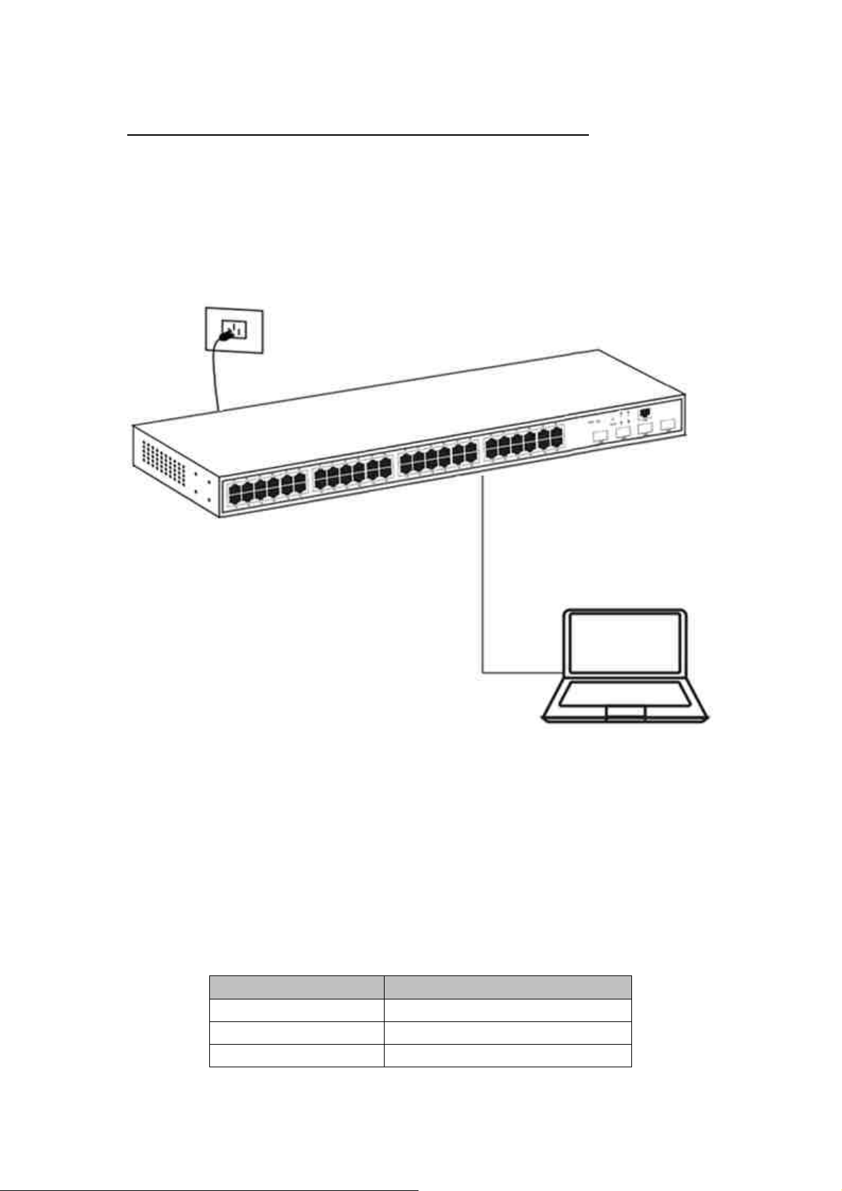
2.2 Connect Computer (NIC) to the Switch
Please insert the NIC into the computer, after installing network card driver,
please connect one end of the twisted pair to RJ-45 jack of your computer, the
other end will be connected to any RJ-45 port of the Switch, the distance
between Switch and computer is around 100 meters. Once the connection is OK
and the devices are power on normally, the LNK/ACT/Speed status indicator lights
corresponding ports of the Switch.
© ALLNET GmbH Computersysteme 2016 - Alle Rechte vorbehalten
Irrtum und Änderungen vorbehalten
12
Page 13
ALL-SG8452M – User Manual
Chapter 3 How to Login the Switch
3.1 Switch to End Node
Use standard Cat.5/5e Ethernet cable (UTP/STP) to connect the Switch to end
nodes as described below. Switch ports will automatically adjust to the
characteristics (MDI/MDI-X, speed, duplex) of the device to which is connected.
Please refer to the LED Indicator Specification. The LINK/ACT/Speed LEDs for each
port lights on when the link is available.
3.2 How to Login the Switch
As the Switch provides Web-based management login, you can configure your
computer’s IP address manually to log on to the Switch. The default settings of
the Switch are shown below.
Parameter Default Value
Default IP address 192.168.2.1
Default username admin
Default password admin
© ALLNET GmbH Computersysteme 2016 - Alle Rechte vorbehalten
Irrtum und Änderungen vorbehalten
13
Page 14
ALL-SG8452M – User Manual
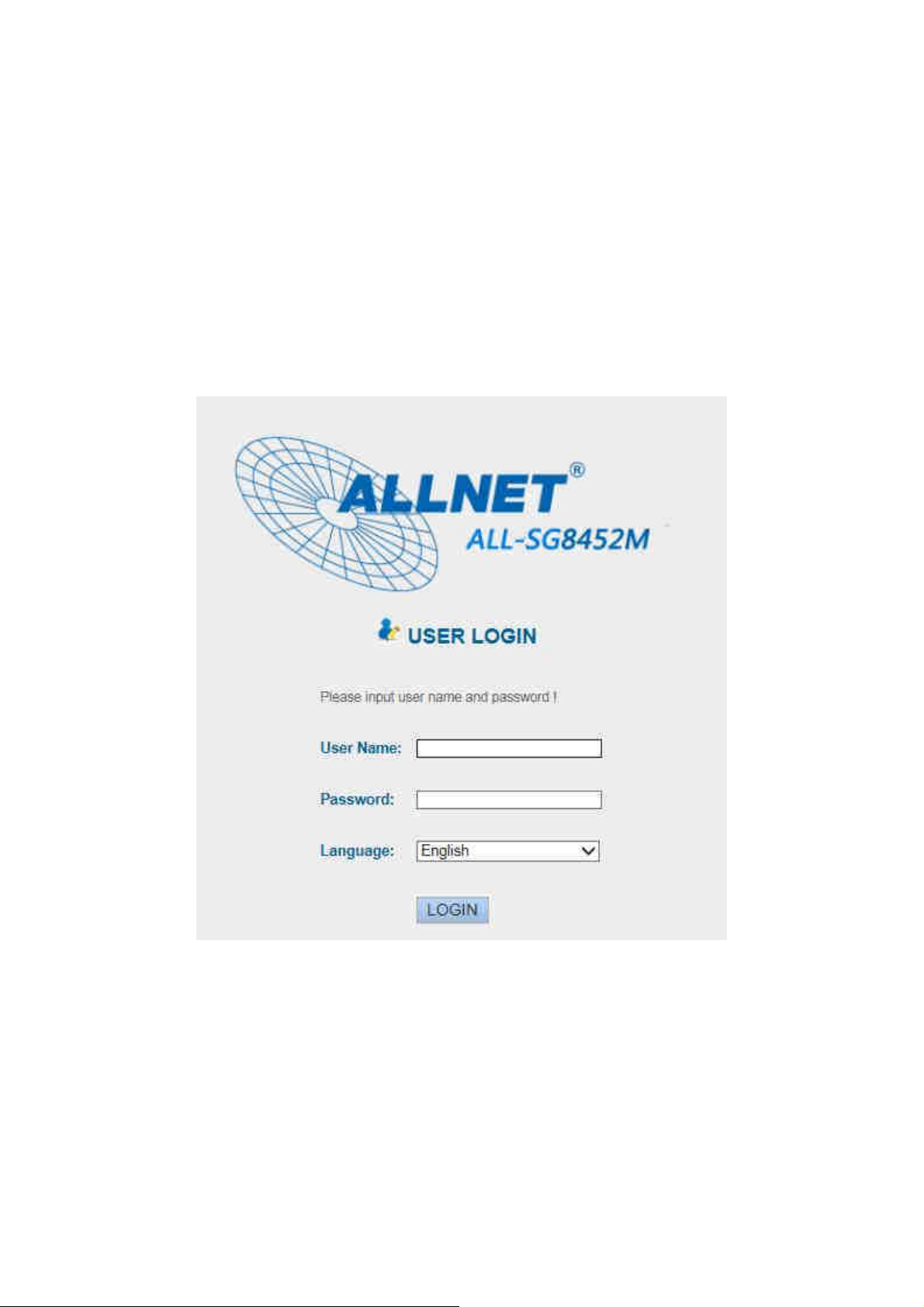
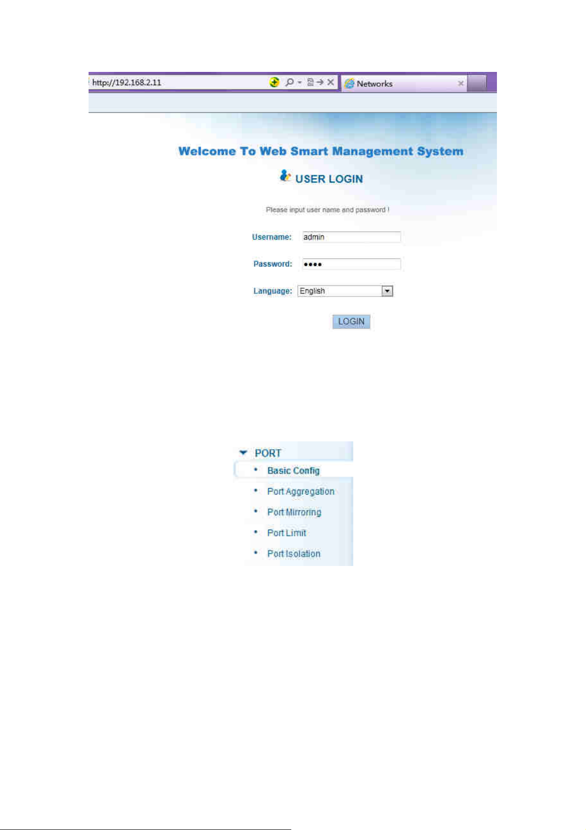
You can log on to the configuration window of the Switch through following
steps:
1. Connect the Switch with the computer NIC interface.
2. Power on the Switch.
3. Check whether the IP address of the computer is within this network
segment: 192.168.2.xxx (“xxx” ranges 2~254), for example, 192.168.2.100.
4. Open the browser, and enter http://192.168.2.1 and then press “Enter”. The
Switch login window appears.
5. Switching language to English. Enter the Username and Password (The
factory default Username is admin and Password is admin), and then click
“Login” to log in to the Switch configuration window as below.
© ALLNET GmbH Computersysteme 2016 - Alle Rechte vorbehalten
Irrtum und Änderungen vorbehalten
14
Page 15
ALL-SG8452M – User Manual
Chapter 4 Switch Configuration
The Web Smart Ethernet Switch Managed switch software provides rich layer 2
functionality for switches in your networks. This chapter describes how to use
Web-based management interface (Web UI) to this switch configure managed
switch software features.
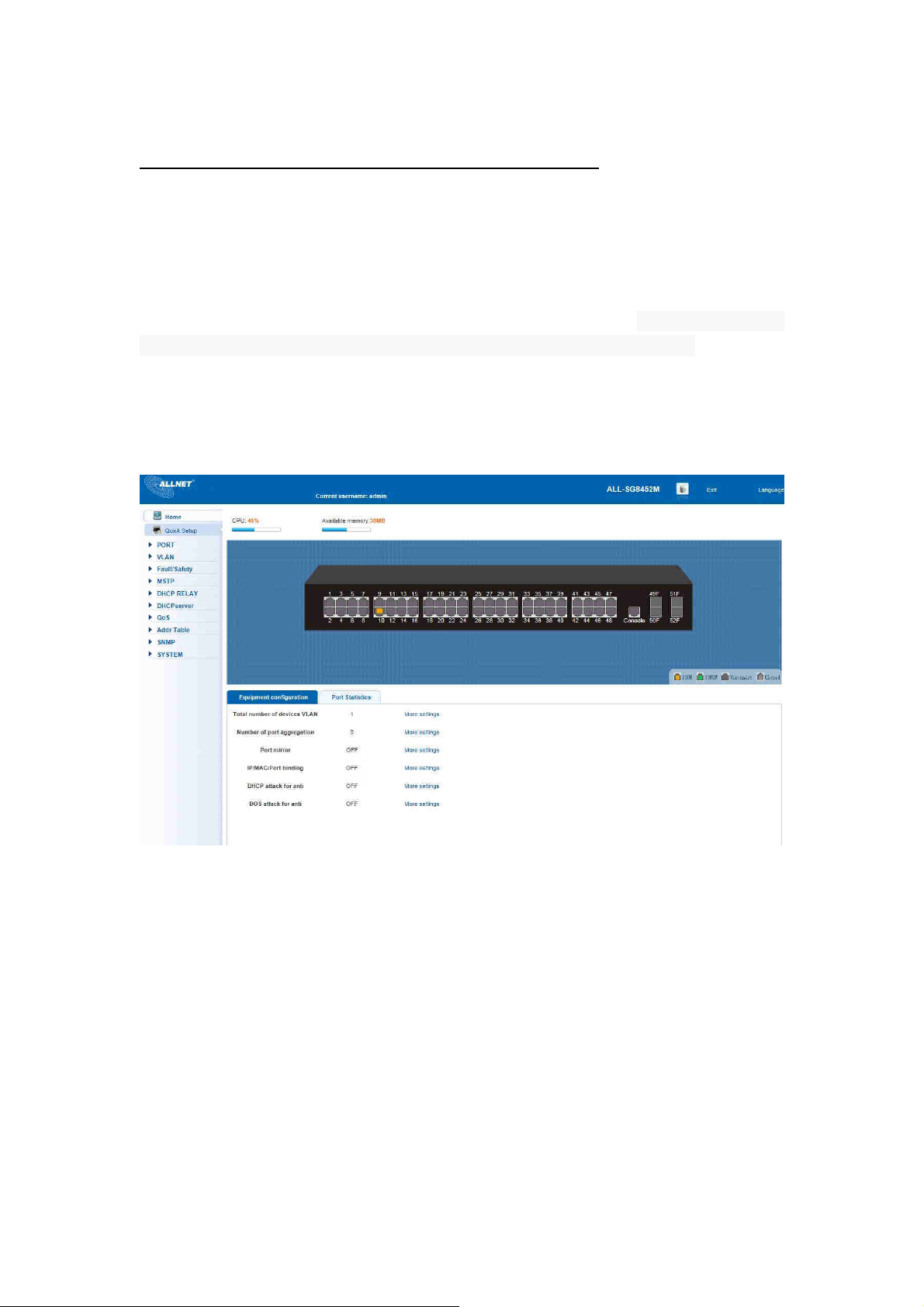
In the Web UI, the left column shows the configuration menu. Above you can see
the information for switch system, such as memory, software version. The middle
shows the switch’s current link status. Green squares indicate the port link is up,
while black squares indicate the port link is down. Below the switch panel, you
can find a common toolbar to provide useful functions for users. The rest of the
screen area displays the configuration settings.
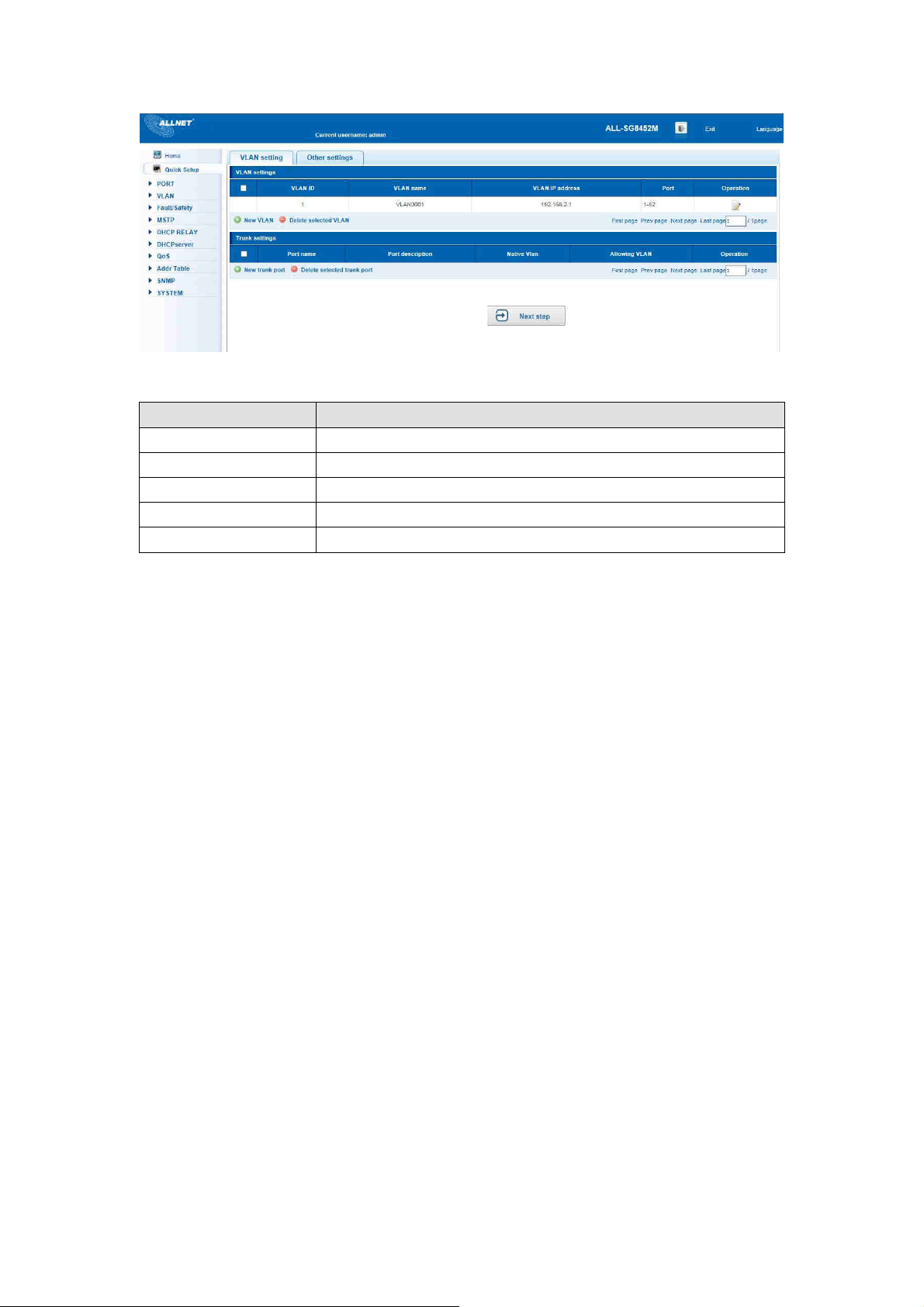
4.1 Quickly setting
In the navigation bar to select “Quick Setup”, can create a VLAN in this module,
add the port in the VLAN, set the basic information and modify the switch login
password. The following picture:
© ALLNET GmbH Computersysteme 2016 - Alle Rechte vorbehalten
Irrtum und Änderungen vorbehalten
15
Page 16
ALL-SG8452M – User Manual
【parameter description】
Parameter Description
VLAN ID VLAN number,48GE default VLAN 1
VLAN name VLAN mark
Manage IP Manage the IP address of the VLAN
device name Switch name
Manage VLAN Switches management in use of the VLAN
【instructions】
Native VLAN: as a Trunk, the mouth will belong to a Native VLAN. The so-called
Native VLAN, is refers to UNTAG send or receive a message on the interface, is
considered belongs to the VLAN. Obviously, the interface of the default VLAN ID
(PVID) in the IEEE 802.1 Q VLAN ID is the Native VLAN. At the same time, send
belong to Native VLAN frame on the Trunk, must adopt UNTAG way.
Allowed VLAN list: a Trunk can transport the equipment support by default all
the VLAN traffic (1-4094). But, also can by setting the permission VLAN Trunk at
the mouth of the list to limit the flow of some VLAN can't through the Trunk.
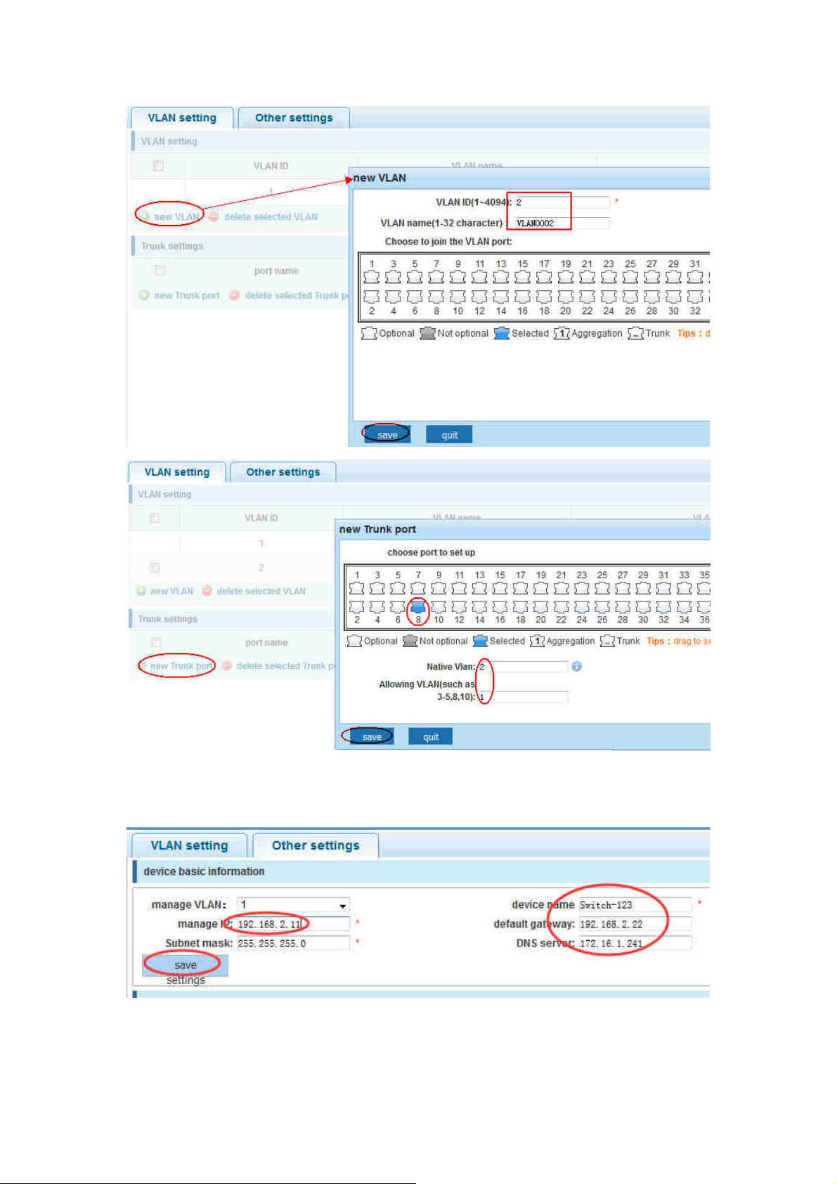
【Configuration example】
1) VLAN setting:such as create VLAN 2 ,Sets the port 8 to Trunk ,Native VLAN 2
© ALLNET GmbH Computersysteme 2016 - Alle Rechte vorbehalten
Irrtum und Änderungen vorbehalten
16
Page 17
ALL-SG8452M – User Manual
2) Click “next step” button, into other settings, such as:manage IP address set as
192.168.2.11, device name set as switch-123 ,default gateway with the DNS server set
as 172.16.1.241
Use 192.168.2.11 to log in, set a new password for 1234
© ALLNET GmbH Computersysteme 2016 - Alle Rechte vorbehalten
Irrtum und Änderungen vorbehalten
17
Page 18
ALL-SG8452M – User Manual
4.2 PORT
In the navigation bar to select “PORT”. You may conduct basic config, port
aggregation, port mirroring , port limit and port isolation.
4.2.1 Basic config
In the navigation bar to select “PORT>basic config”. For panel port to port
described, port speed, port status, working mode, flow control, cross line order
configuration, the following picture:
© ALLNET GmbH Computersysteme 2016 - Alle Rechte vorbehalten
Irrtum und Änderungen vorbehalten
18
Page 19
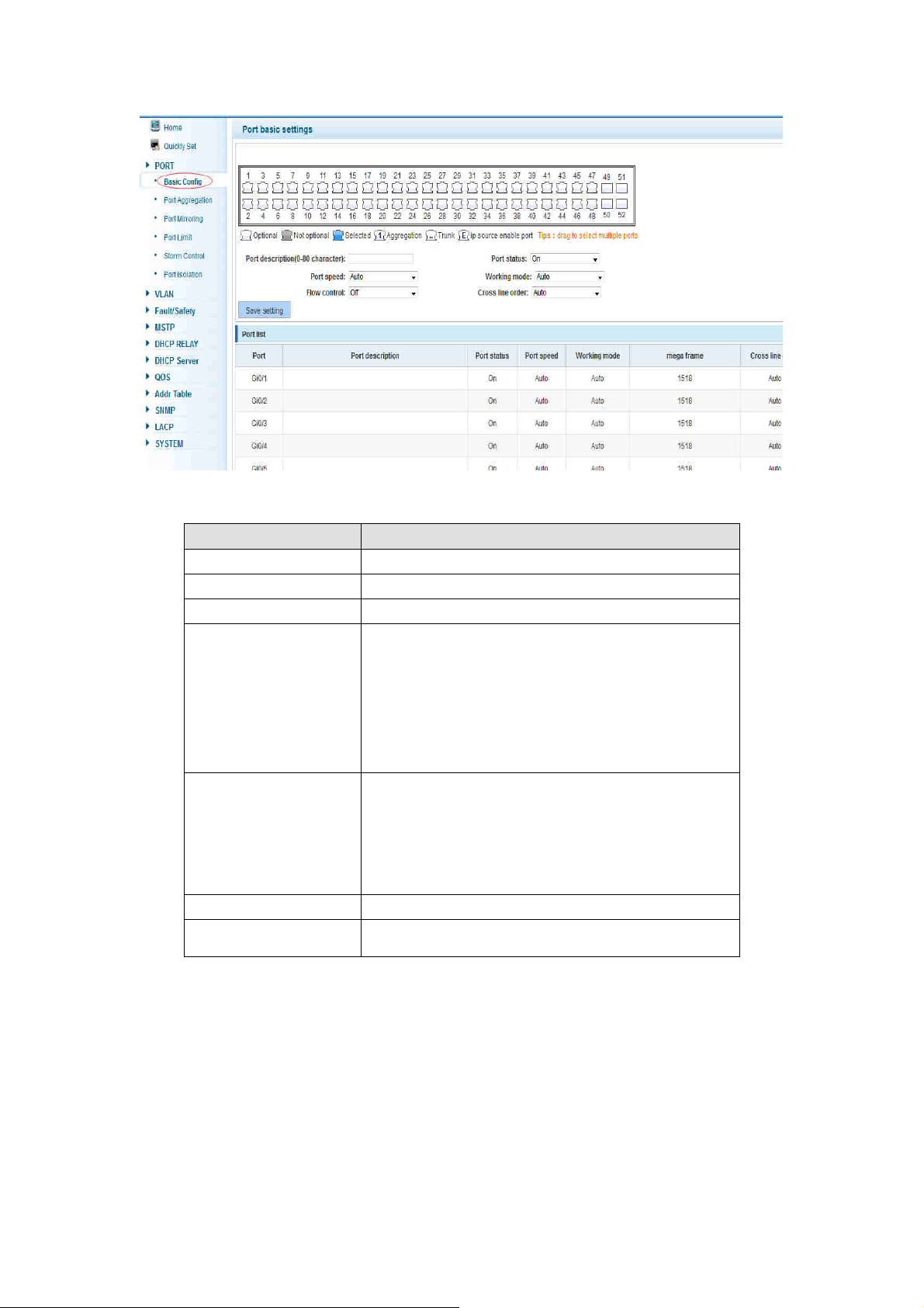
【parameter description】
parameter description
port Select the current configuration port number
port status Choose whether to close link port
flow control Whether open flow control
ALL-SG8452M – User Manual
Can choose the following kinds:
Aggregation
port speed
10 M
100 M
1000 M
Can choose the following kinds:
Self negotiated
working mode
10 M
100 M
1000 M
port described The port is described
Cross line sequence Whether open intersection line sequence
【instructions】
Open flow control should be negotiated will close, negotiated close is to set port
speed rate and working mode; Set the port rate more than actual rate of port, the
port will be up.
【Configuration example】
Such as:The port is set to 10 M, half duplex, open flow control and cross line
sequence and port state
© ALLNET GmbH Computersysteme 2016 - Alle Rechte vorbehalten
Irrtum und Änderungen vorbehalten
19
Page 20
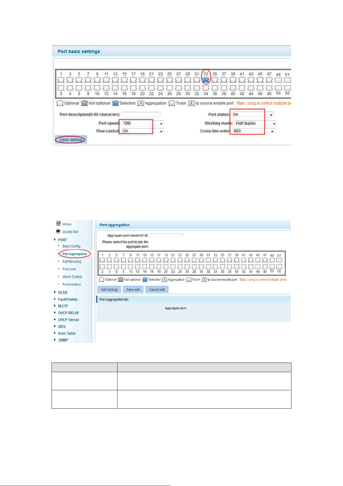
4.2.2 Port aggregation
ALL-SG8452M – User Manual
In the navigation bar to select “PORT>port aggregation”. In order to expand the
port bandwidth or achieve the bandwidth of the redundancy backup, the following
picture:
【parameter description】
parameter description
52GE switch can be set up eight link trunk group, group_1
Aggregation port
to group_8
For each of the members of the group and add your own
Member port
port, and with members of other groups
【instructions】
Open the port of the ARP check function, the port of the important device ARP, the
port of the VLAN MAC function, and the monitor port in the port image can’t be
© ALLNET GmbH Computersysteme 2016 - Alle Rechte vorbehalten
Irrtum und Änderungen vorbehalten
20
Page 21
ALL-SG8452M – User Manual
added!
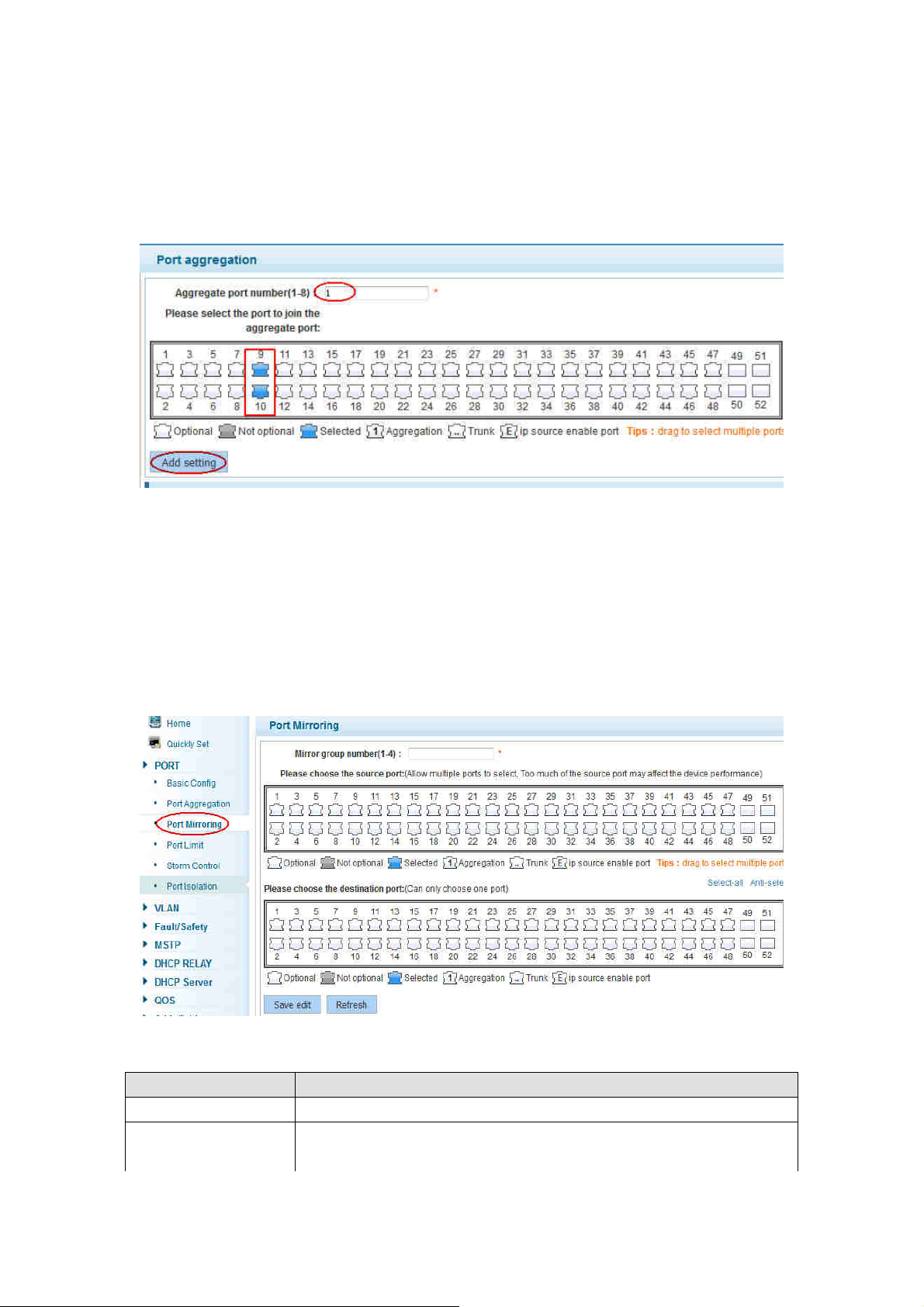
【Configuration example】
Such as: set the port 9, 10, for aggregation port 1, lets this aggregation port 1
connected to other switch aggregation port 1 to build switch links .
4.2.3 Port mirroring
In the navigation bar to select “PORT>port mirroring”,Open port mirror feature,All
packets on the source port are copied and forwarded to the destination
port,Destination port is usually connected to a packet analyzer to analyze the source
port,Multiple ports can be mirrored to a destination port,the following picture:
【parameter description】
parameter description
Source port To monitor the port in and out of flow
Destination port
Set destination port,All packets on the source port are copied
and forwarded to the destination port
© ALLNET GmbH Computersysteme 2016 - Alle Rechte vorbehalten
Irrtum und Änderungen vorbehalten
21
Page 22
ALL-SG8452M – User Manual
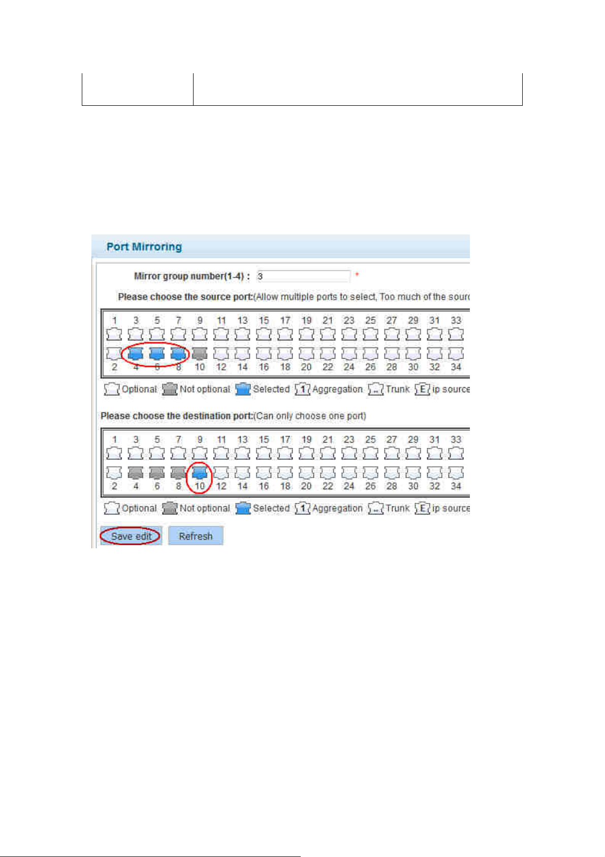
Mirror group
Range :1-4
【instructions】
The port of the aggregate port can not be used as a destination port and the source
port, destination port and source port can not be the same.
【Configuration example】
Such as: set a mirror group for port 10 regulatory port 4, 6, 8 on and out flow
conditions
4.2.4 Port rate-limit
In the navigation bar to select “PORT>port rate-limit”.
To port output, input speed limit, the following picture:
© ALLNET GmbH Computersysteme 2016 - Alle Rechte vorbehalten
Irrtum und Änderungen vorbehalten
22
Page 23
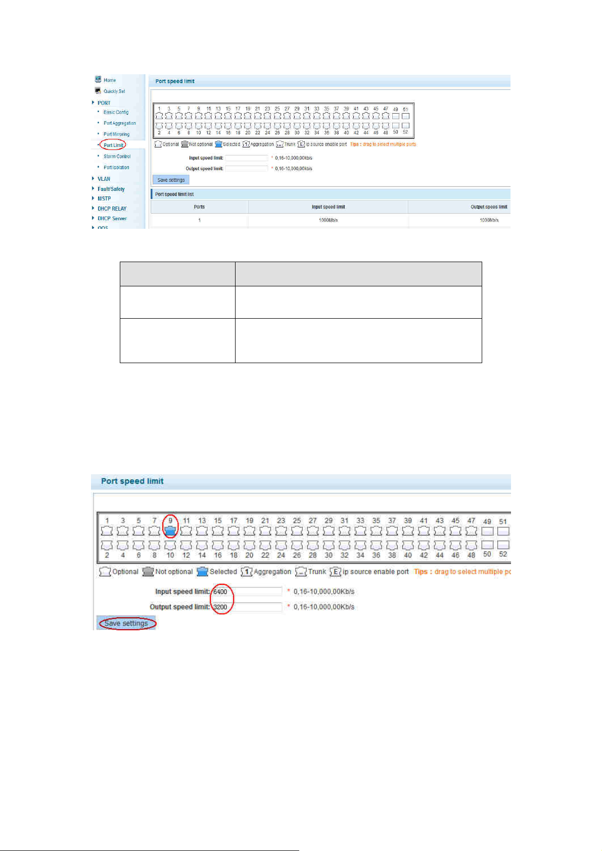
【parameter description】
ALL-SG8452M – User Manual
parameter
description
Set port input speed
Input speed limit
Set port output speed
Output speed limit
【instructions】
1 Mbit/s = 1000 Kbit/s = 1000 / 8 KB/s = 125 KB/s . That is, the theoretical rate of 1M
bandwidth is125KB/s .
【Configuration example】
Such as: the port 9 input rate is set to 6400 KB/s, the output rate is set to 3200 KB/s
4.2.5 Storm control
In the navigation bar to select “PORT>Storm control”,
To port storm control config, the following picture:
© ALLNET GmbH Computersysteme 2016 - Alle Rechte vorbehalten
Irrtum und Änderungen vorbehalten
23
Page 24
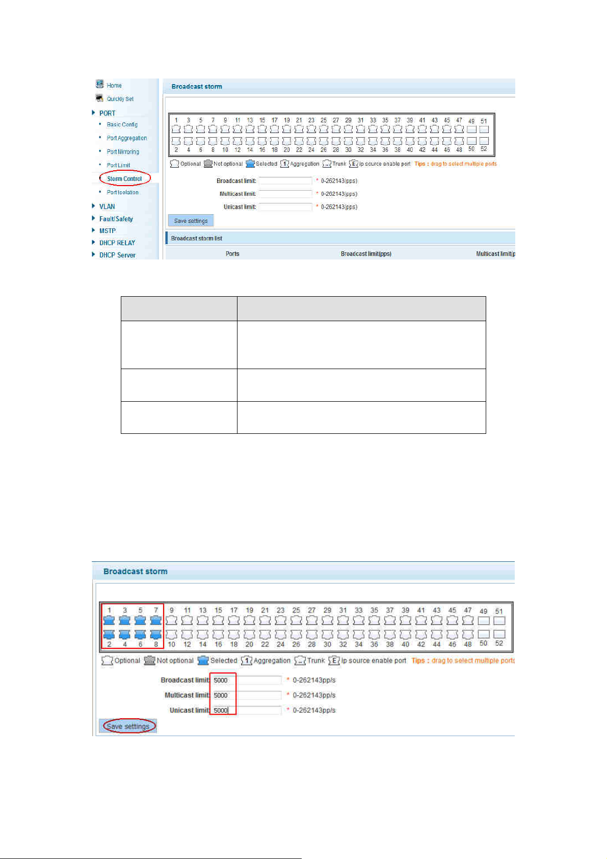
【parameter description】
ALL-SG8452M – User Manual
parameter
description
Storm suppression value of the broadcast
Broadcast
suppression value
Multicast
suppression value
Unicast suppression
value
packets
Storm suppression value of the multicast
packets
Storm suppression value of the unicast packets
【instructions】
1 Mbit/s = 1000 Kbit/s = 1000 / 8 KB/s = 125 KB/s. That is, the theoretical rate of 1M
bandwidth is125KB/s.
【Configuration example】
Such as: should be forwarded to the port 1-8 of all kinds of packet forwarding rate is
5000 KB/s
© ALLNET GmbH Computersysteme 2016 - Alle Rechte vorbehalten
Irrtum und Änderungen vorbehalten
24
Page 25
ALL-SG8452M – User Manual
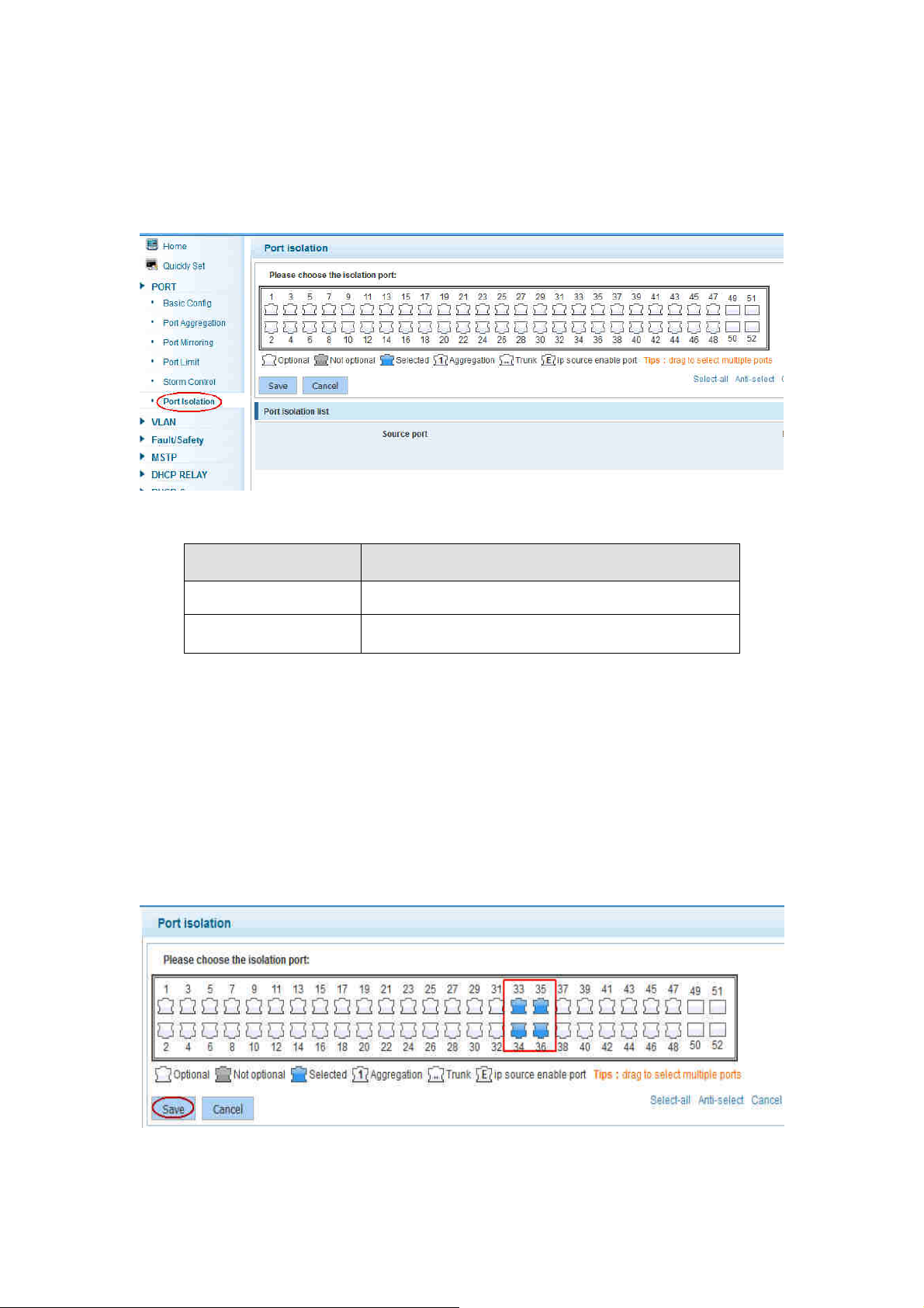
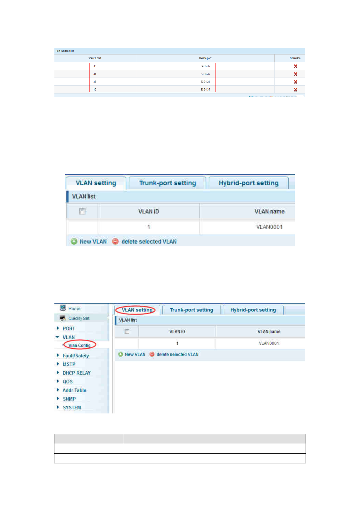
4.2.6 Port isolation
In the navigation bar to select “PORT>port isolation”, ports are isolated. The
following picture:
【parameter description】
parameter
description
Source port Choose a port, to configure the isolated port
Isolated port
Port will be isolated
【instructions】
Open port isolation function, All packets on the source port are not forwarded from
the isolated port, the selected ports are isolated.
Ports that have been added to the aggregate port aren't also capable of being a
destination port and source port, destination port and source port cannot be the
same
【Configuration example】
Such as: the port 3, 4, 5, and 6 ports are isolated
© ALLNET GmbH Computersysteme 2016 - Alle Rechte vorbehalten
Irrtum und Änderungen vorbehalten
25
Page 26
ALL-SG8452M – User Manual
4.3 VLAN
In the navigation bar to select “VLAN”. You can manage the VLAN config, Trunk
Settings and Hybrid Settings. The following picture:
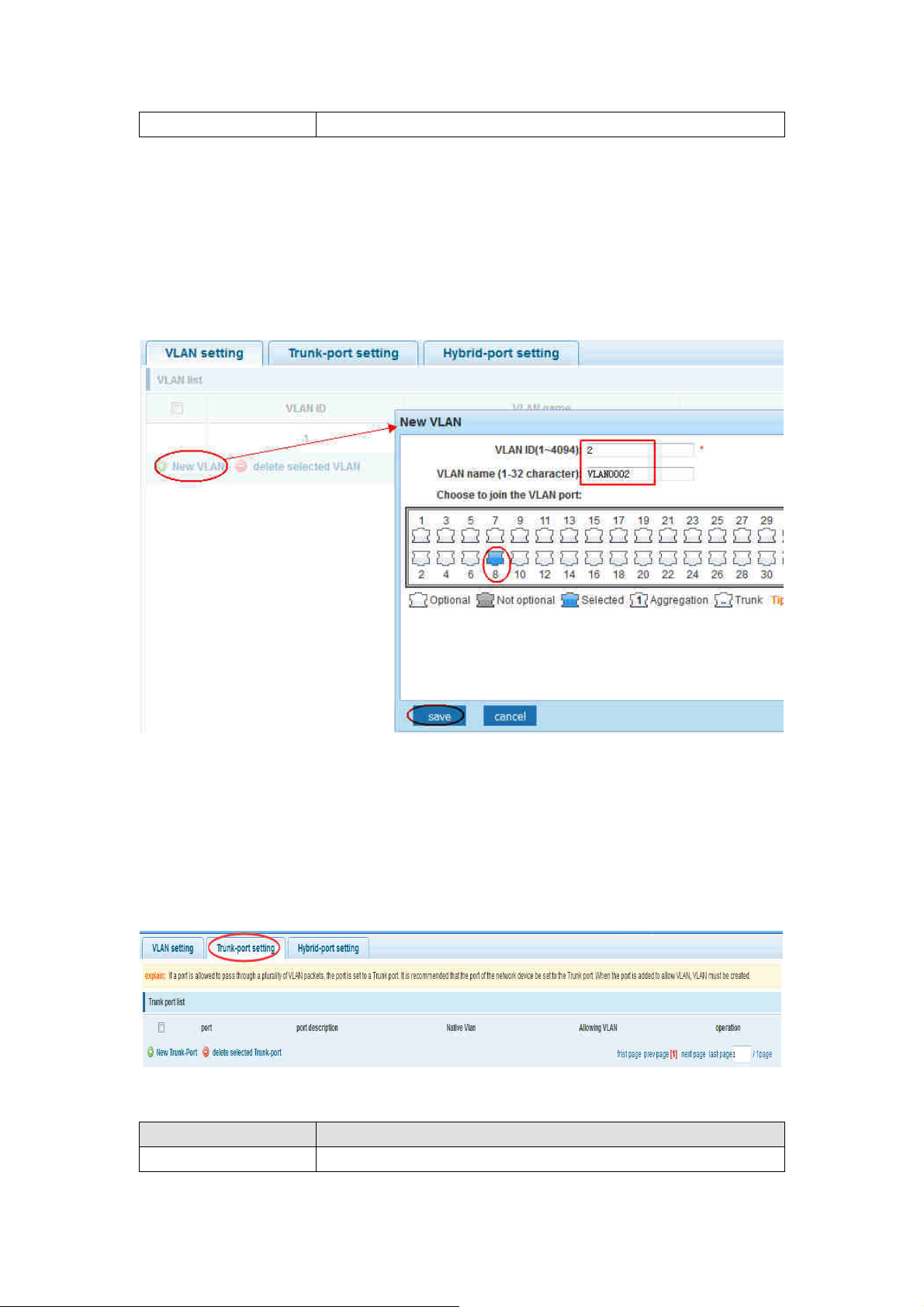
4.3.1 VLAN config
In the navigation bar to select “VLAN config”. VLANs can be created and set the
port to the VLAN (port default state for the access mode) ,the following picture
【parameter description】
parameter description
VLAN ID VLAN number,48GE default VLAN 1
VLAN name VLAN mark
© ALLNET GmbH Computersysteme 2016 - Alle Rechte vorbehalten
Irrtum und Änderungen vorbehalten
26
Page 27
ALL-SG8452M – User Manual
VLAN IP address Manage switch ip address
【instructions】
Management VLAN, the default VLAN cannot be deleted. Add ports to access port,
port access mode can only be a member of the VLAN.
【Configuration example】
Such as: connect switches pc1, pc2 couldn't ping each other, will be one of the PC
connection port belongs to a VLAN 2
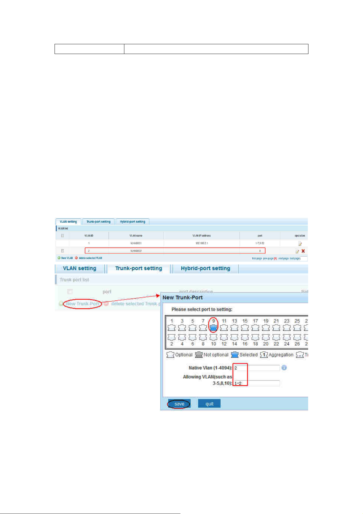
4.3.2 Trunk-port setting
In the navigation bar to select “VLAN config>trunk-port setting”, Can set port to
Trunk port, the following picture:
【parameter description】
parameter description
Native VLAN Only set one
© ALLNET GmbH Computersysteme 2016 - Alle Rechte vorbehalten
Irrtum und Änderungen vorbehalten
27
Page 28
ALL-SG8452M – User Manual
Allowing VLAN Can set up multiple
【instructions】
Native VLAN: as a Trunk, the mouth will belong to a Native VLAN. The so-called
Native VLAN, is refers to UNTAG send or receive a message on the interface, is
considered belongs to the VLAN. Obviously, the interface of the default VLAN ID
(PVID) in the IEEE 802.1 Q VLAN ID is the Native VLAN. At the same time, send belong
to Native VLAN frame on the Trunk, must adopt UNTAG way.
Allowed VLAN list: a Trunk can transport the equipment support by default all the
VLAN traffic (1-4094). But, also can by setting the permission VLAN Trunk at the
mouth of the list to limit the flow of some VLAN can't through the Trunk.
【Configuration example】
Such as:PVID=VLAN2
PC1:192.168.2.122, port 8, access VLAN2
PC2:192.168.2.123, port 9, Trunk allowed VLAN 1-2
PC3:192.168.2.124, port 10, access VLAN1(The default port belongs to VLAN1)
Can let the PC2 PING PC1, cannot PING PC3
© ALLNET GmbH Computersysteme 2016 - Alle Rechte vorbehalten
Irrtum und Änderungen vorbehalten
28
Page 29
ALL-SG8452M – User Manual
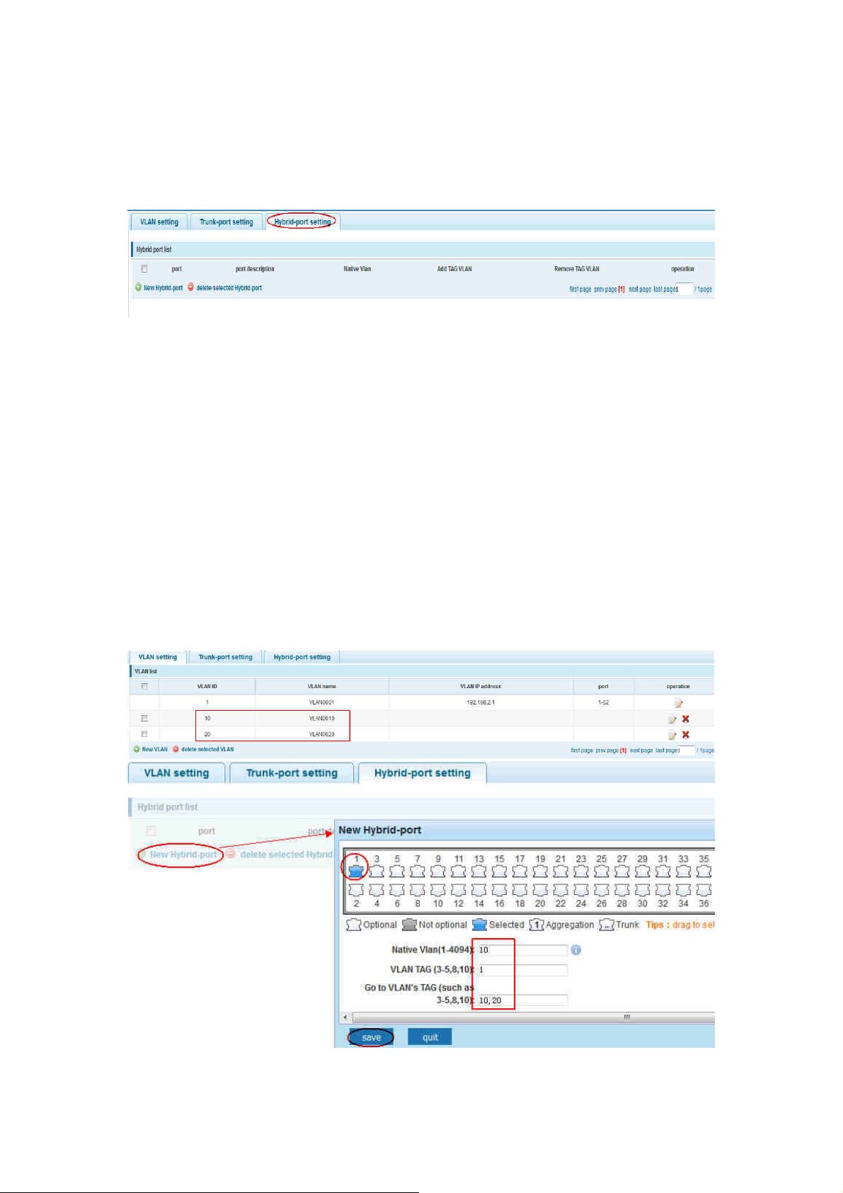
4.3.3 Hybrid-port setting
In the navigation bar to select “VLAN config>hybrid-port setting”, Can set the
port to take the tag and without the tag ,the following picture:
【instructions】
Hybrid port to packet:
Receives a packet, judge whether there is a VLAN information: if there is no play in
port PVID, exchanged and forwarding, if have, whether the Hybrid port allows the
VLAN data into: if can be forwarded, or discarded (untag on port configuration is not
considered, untag configuration only work when to send it a message)
Hybrid port to send packet:
1, determine the VLAN in this port attributes (disp interface can see the port to which
VLAN untag, which VLAN tag)
2, if it is untag stripping VLAN information, send again, if the tag is sent directly
【Configuration example】
Such as: create vlans 10, 20, VLAN sets the Native VLAN port 1 to 10, to tag VLAN for
10, 20, sets the Native VLAN port 2 to 20, to tag VLAN for 10, 20
© ALLNET GmbH Computersysteme 2016 - Alle Rechte vorbehalten
Irrtum und Änderungen vorbehalten
29
Page 30
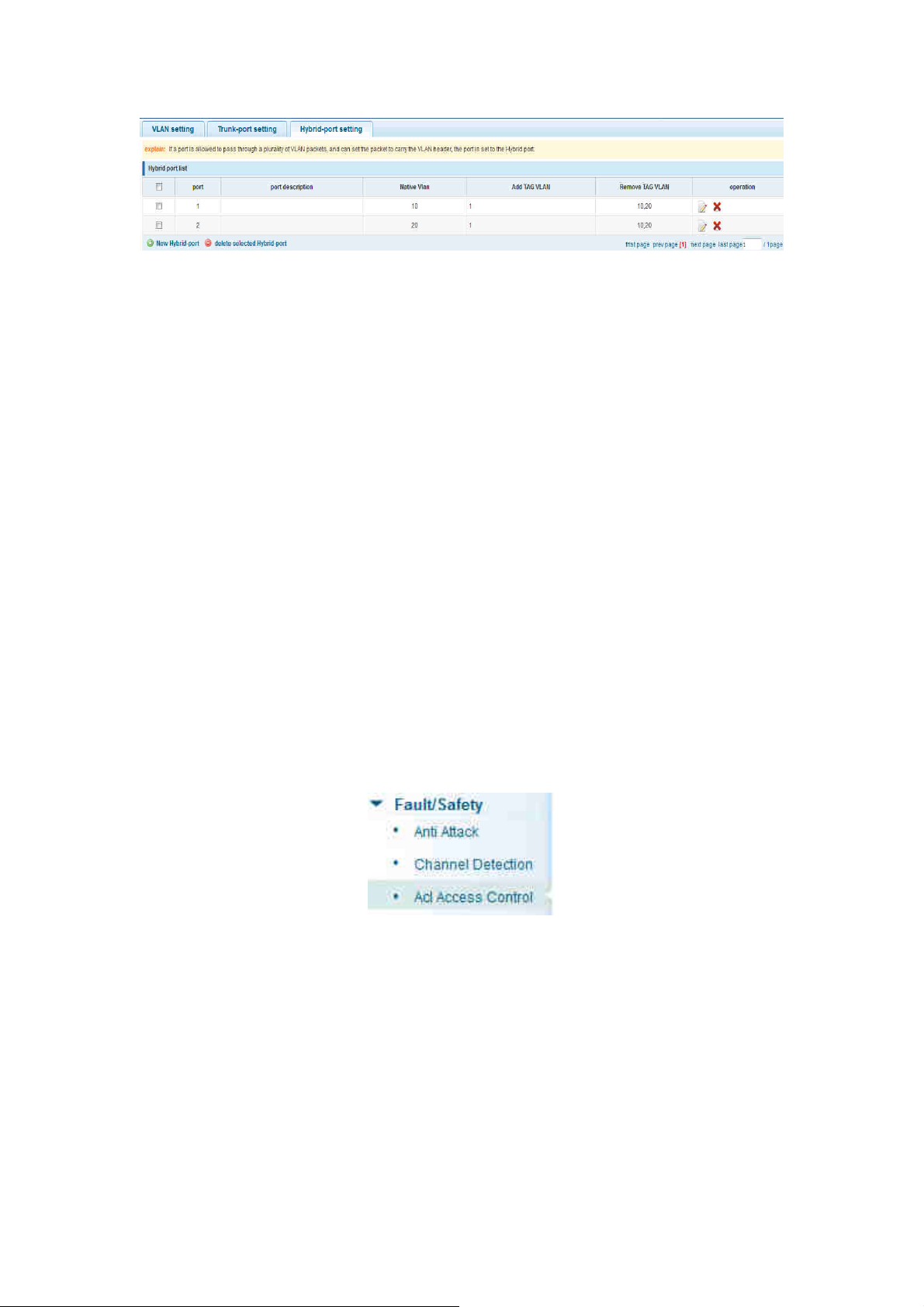
ALL-SG8452M – User Manual
This system e0/1 and the receive system e0/2 PC can be exchanged, but when each
data taken from a VLAN is different.
Data from the pc1, by inter0/1 pvid VLAN10 encapsulation VLAN10 labeled into
switches, switch found system e0/2 allows 10 data through the VLAN, so the data is
forwarded to the system e0/2, because the system e0/2 VLAN is untagged 10, then
switches at this time to remove packet VLAN10 tag, in the form of ordinary package
sent to pc2, pc1 - > p2 is VLAN10 walking at this time
Again to analyze pc2 gave pc1 package process, data from the pc2, by inter0/2 pvid
VLAN20 encapsulation VLAN20 labeled into switch, switch found system e0/1 allows
VLAN by 20 data, so the data is forwarded to the system e0/1, because the system
e0/1 on the VLAN is untagged 20, then switches remove packets on VLAN20 tag at
this time, in the form of ordinary package sent to pc1, pc2 at this time - > pc1 is VLAN
20
4.4 Fault/Safety
In the navigation bar to select “fault/safety”. You can set anti attack、channel
detection and ACL access control configuration 。
4.4.1 Anti attack
4.4.1.1 Anti DHCP attack
In the navigation bar to select “fault/safety>anti attack>anti dhcp attack”. Open
the DHCP anti-attack function, intercepting counterfeit DHCP server and address
depletion attack packets ban kangaroo DHCP server, the following picture:
© ALLNET GmbH Computersysteme 2016 - Alle Rechte vorbehalten
Irrtum und Änderungen vorbehalten
30
Page 31

ALL-SG8452M – User Manual
【instructions】
DHCP trusted port configuration. Select the port as a trusted port. Prohibit DHCP for
address, select the port and save, you can disable this feature for the port。
Open DHCP attack prevention function, need to set the DHCP protective vlan
simultaneously, other functions to take effect.
【Configuration example】
Such as:1.dhcp snooping open
2.Setting dhcp snooping vlan
Set the connection router 10 ports for trust, then 12 port is set to the prohibit
© ALLNET GmbH Computersysteme 2016 - Alle Rechte vorbehalten
Irrtum und Änderungen vorbehalten
31
Page 32

ALL-SG8452M – User Manual
3.Verify source mac F0:DE:F1:12:98:D2,set server ip address to 192.168.2.1
4.Set option82 information
© ALLNET GmbH Computersysteme 2016 - Alle Rechte vorbehalten
Irrtum und Änderungen vorbehalten
32
Page 33

5.The port 7 for binding
ALL-SG8452M – User Manual
4.4.1.2 Anti DOS
In the navigation bar to select“fault/safety>anti attack>anti dhcp attack”,Open
the anti DOS attack function, intercept Land attack packets, illegal TCP packets, to
ensure that the device or server to provide normal service to legitimate users.,the
following picture:
【instructions】
Open the anti DOS attack function, intercept Land attack packets, illegal TCP packets,
to ensure that the device or server to provide normal service to legitimate users.
【Configuration example】
Such as:Open the anti DOS attack function
© ALLNET GmbH Computersysteme 2016 - Alle Rechte vorbehalten
Irrtum und Änderungen vorbehalten
33
Page 34

ALL-SG8452M – User Manual
4.4.1.3 IPsource guard
In the navigation bar to select“fault/safety>anti attack>ip source
guard”,Through the source port security is enabled, on port forwarding the packet
filter control, prevent illegal message through the port, thereby limiting the illegal
use of network resources, improve the safety of the port,the following picture:
【instructions】
Add the port that is currently being used as a IP source protection enable port, the
port will not be able to use.
【Configuration example】
Such as: to open source IP protection enabled port first,then to binding
© ALLNET GmbH Computersysteme 2016 - Alle Rechte vorbehalten
Irrtum und Änderungen vorbehalten
34
Page 35

ALL-SG8452M – User Manual
4.4.1.4 Anti three bind
In the navigation bar to select“fault/safety>anti attack>anti three
bind”,Automatically detect the port based IP address, MAC address of the mapping
relationship, and then realize the function of a key binding,the following picture:
【instructions】
A bond must be bound before the binding to enable the switch to open,And if you
want to access shall be binding and switch the IP address of the same network
segment 。
【Configuration example】
Such as: the binding to make first can open, must be a key bindings port 7
© ALLNET GmbH Computersysteme 2016 - Alle Rechte vorbehalten
Irrtum und Änderungen vorbehalten
35
Page 36

ALL-SG8452M – User Manual
Can check the delete option.
4.4.2 Channel detection
4.4.2.1 Ping testing
In the navigation bar to select“fault/safety> channel detection>ping
testing”,Use ping function to test internet connect and host whether to arrive. The
following picture :
© ALLNET GmbH Computersysteme 2016 - Alle Rechte vorbehalten
Irrtum und Änderungen vorbehalten
36
Page 37

ALL-SG8452M – User Manual
【parameter description】
parameter description
destination IP
address Fill in the IP address of the need to detect
Timeout period Range of 1 to 10
Repeat number Testing number
【instructions】
Use ping function to test internet connect and host whether to arrive.
【Configuration example】
Such as: PING connect the IP address of the PC
4.4.2.2 Tracert testing
In the navigation bar to select“fault/safety> channel detection>tracert
testing”,Tracert detection can detect to the destination through the .following
picture :
© ALLNET GmbH Computersysteme 2016 - Alle Rechte vorbehalten
Irrtum und Änderungen vorbehalten
37
Page 38

ALL-SG8452M – User Manual
【parameter description】
parameter description
destination IP
address Fill in the IP address of the need to detect
Timeout period Range of 1 to 10
【instruction】
the function is used to detect more is up to and reach the destination path. If a
destination unreachable, diagnose problems.
【Configuration example】
Such as: PING connect the IP address of the PC
4.4.2.3 Cable testing
In the navigation bar to select“fault/safety> channel detection>cable tracert
testing”,Can detect connection device status ,the following picture:
© ALLNET GmbH Computersysteme 2016 - Alle Rechte vorbehalten
Irrtum und Änderungen vorbehalten
38
Page 39

【Configuration example】
ALL-SG8452M – User Manual
4.4.3 ACL
In the navigation bar to select“fault/safety>ACL”,Can be applied to port ACL rules
and Settings to take effect in time
© ALLNET GmbH Computersysteme 2016 - Alle Rechte vorbehalten
Irrtum und Änderungen vorbehalten
39
Page 40

ALL-SG8452M – User Manual
【instruction】
The ACL rules are sequenced, row in front of the match will be priority rule. Many, if
the strategy items operating time is relatively longer.
Basic principles:
1, according to the order, as long as there is a meet, will not continue to find
2, implied refused, if don't match, so must match the final implied refused entry,
cisco default
3, any only under the condition of the minimum permissions to the user can satisfy
their demand
4, don't forget to apply the ACL to the port
【Configuration example】
such as: test time is every Monday to Friday 9 to 18 points, set port 1-8 cannot access
the network
steps: building ACL time - building ACL rules - is applied to the port
© ALLNET GmbH Computersysteme 2016 - Alle Rechte vorbehalten
Irrtum und Änderungen vorbehalten
40
Page 41

4.5 MSTP
ALL-SG8452M – User Manual
In the navigation bar to select“MSTP”,you can set to the MSTP region and MSTP
bridge configuration。
4.5.1 MSTP region
In the navigation bar to select“MSTP>MSTP region”,Can modify the domain and
domain name, add instance is mapped to a VLAN.the following picture
© ALLNET GmbH Computersysteme 2016 - Alle Rechte vorbehalten
Irrtum und Änderungen vorbehalten
41
Page 42

ALL-SG8452M – User Manual
【parameter description】
parameter description
Region name Configure the region name
Revision level Parameter configuration revision level
Instance ID Select configuration instance ID
VLAN ID Mapping of the VLAN configuration instance
【instruction】
An instance can only be mapped to a VLAN, instance and VLAN is a one-to-one
relationship.
【Configuration example】
Such as: change the region to DEADBEEF0102, region name is 123, instance 4 is
mapped to a VLAN 2, in the first need to create a VLAN 2
4.5.2 MSTP bridge
In the navigation bar to select“MSTP>MSTP bridge”,Can be related to bridge, port
configuration,the following picture:
© ALLNET GmbH Computersysteme 2016 - Alle Rechte vorbehalten
Irrtum und Änderungen vorbehalten
42
Page 43

ALL-SG8452M – User Manual
【parameter description】
parameter description
inst-priority Whether open instance priority setting
Instance ID Select the created instance id is configured
enable Whether to open the STP bridge function
Bridge priority
Priority setting bridge example, the default
instance bridge priority for 32768
mode The model is divided into: the STP, RSTP, MSTP
Hello-time Switches sends bpdus in packet interval
Max-age
Ports are not yet received a message in the
time, will initiate topology changes
Forward-delay The state of the port switch time
Port-priority
Set port instance priority, defaults to 128, you
must enter multiple of 16, the range of 0-240
Path-cost Configure port costs
Port-fast Select configuration state
Auto-ege Select configuration state
Point-to-point Select configuration state
Bpdu guard Select configuration state
Bpdu filter Select configuration state
compatible Select configuration state
Root guard Select configuration state
TC guard Select configuration state
TC filter Select configuration state
【instruction】
(1) (hello_time+1)×2<=max_age<=(f_delay-1)×2 ,enable the switch to set instance
priority.
(2) Enable STP or switch mode would spend 2 times of the forward delay time.
© ALLNET GmbH Computersysteme 2016 - Alle Rechte vorbehalten
Irrtum und Änderungen vorbehalten
43
Page 44

ALL-SG8452M – User Manual
【Configuration example】
Such as:1)Open the STP, configuration has to create an instance of the priority,
configuration time parameters, set the pattern to MSTP
2)Set MSTP has launched port configuration, select the created instance, set priority
(port configuration is not online, on-line configuration will only take effect, can click
on the "view the current configuration" button to view the configured completed)
© ALLNET GmbH Computersysteme 2016 - Alle Rechte vorbehalten
Irrtum und Änderungen vorbehalten
44
Page 45

ALL-SG8452M – User Manual
4.6 DHCP relay
In the navigation bar to select“DHCP relay”,you can set to the DHCP relay and
option82。
© ALLNET GmbH Computersysteme 2016 - Alle Rechte vorbehalten
Irrtum und Änderungen vorbehalten
45
Page 46

ALL-SG8452M – User Manual
4.6.1 DHCP relay
In the navigation bar to select“DHCP relay”,Open the DHCP relay function, set up
and view the relay server IP address and its status.the following picture
【parameter description】
parameter description
IP address DHCP server address
status Invalid and vaild
【instruction】
If open the function of relay agent, then receives the broadcast DHCP message, to be
delivered in the form of unicast to configure on the server. The DHCP server to IP and
switches in the same network segment will only take effect.
【Configuration example】
Such as:setting DHCP server ip for 192.168.2.22
© ALLNET GmbH Computersysteme 2016 - Alle Rechte vorbehalten
Irrtum und Änderungen vorbehalten
46
Page 47

ALL-SG8452M – User Manual
4.6.2 0ption82
In the navigation bar to select“DHCP relay>option82”,can set to OPTION82circuit
control、proxy remote 、ip address。the following picture:
【parameter description】
parameter description
VLAN id the DHCP request message in the VLAN, value range is 1
~ 4094
Circuit control Circuit ID to populate the user custom content, scope of
string length is 3 ~ 63
Proxy remote Configuration ASCII remote id string value, the length of
the range of 1 ~ 63
IP address Decimal IP address
【instruction】
Switches, relay information to the DHCP server will take option82, VLAN ID must be
configured to DHCP message taken VLAN can bring option82 information.
【Configuration example】
Sach as:add circuit control、proxy remote、ip address information
© ALLNET GmbH Computersysteme 2016 - Alle Rechte vorbehalten
Irrtum und Änderungen vorbehalten
47
Page 48

ALL-SG8452M – User Manual
4.7 DHCP Server
4.7.1 DHCP Config
In the navigation bar to select“DHCP server”,Can open the DHCP server function,
setting up the network parameters.the following picture:
【instruction】
If open the DHCP server function, can't open the DHCP relay function; Open a DHCP
server is enabled, need to configure and manage the IP in the same network
segment address pool.
© ALLNET GmbH Computersysteme 2016 - Alle Rechte vorbehalten
Irrtum und Änderungen vorbehalten
48
Page 49

ALL-SG8452M – User Manual
【Configuration example】
Such as: to switch a 192.168.2.30-192.168.2.35 bottom allied equipment distribution
within the scope of the IP address, the lease time for 1 day, the default network
management, the DNS server is configured to 192.168.2.22, package option to carry
information from the server.
1)Open the DHCP server;
2) set the address pool network 192.168.2. X, start IP for 192.168.2.30, end IP for
192.68.2.35, the lease time is 1 day;
2)Set the gateway config is 192.168.2.22
3)Set the DNS config is 192.168.2.22
© ALLNET GmbH Computersysteme 2016 - Alle Rechte vorbehalten
Irrtum und Änderungen vorbehalten
49
Page 50

4) port to a PC,ip set to automatic
4) the information package with the option to set up a server;
ALL-SG8452M – User Manual
4.8 QoS
In the navigation bar to select“QoS”,you can set to the Remark、queue config and
mapping the queue。
4.8.1 Remark
In the navigation bar to select“QoS>Remark”,According to the rules for port traffic
bag tag or queue map。the following picture
© ALLNET GmbH Computersysteme 2016 - Alle Rechte vorbehalten
Irrtum und Änderungen vorbehalten
50
Page 51

ALL-SG8452M – User Manual
【parameter description】
parameter parameter
By setting the rule of heavy tag index number, the current
Rule index
switch can be set up 32 rule
Choose always said - match the match, all the data for tags
Choose can be set to equal matching rules, comply with the
Operation type
rules of heavy tag data
Adaptable to the rules of the heavy tag which data is mapped
Server class mapping
to a queue
Conform to the rules of heavy tag data to the marked priority
Priority relable
values
Set heavy tag matching rules, such as choice goal Mac, just
check the data destination Mac address is in accordance with
Value tye
the rules
Set the value of matching, such as choice goal Mac for HH: HH:
value
HH: HH: HH: HH
Choose port to
config The application of heavy tag on which interface
apply Click on the application of heavy marking rules to take effect
【instruction】
According to the different matching rules to map different packages to different
cos, and then according to the mapping relationship cos and queue queue to map
different packages to different queue, can also set the priority value of a tag heavy
bag.
【Configuration example】
Such as: will the destination address for 00:02:03:0b:89:12 packets are forwarded to
the port 3, 4, 5, 6, priority of remarked as 3
© ALLNET GmbH Computersysteme 2016 - Alle Rechte vorbehalten
Irrtum und Änderungen vorbehalten
51
Page 52

ALL-SG8452M – User Manual
4.8.2 Queue config
In the navigation bar to select“ QoS>queue config”,Can be set up queue
scheduling policy 。the following picture:
【parameter description】
parameter description
Can choose four kinds of modes:
RR round-robin scheduling
SP absolute priority scheduling
WRR weighted round-robin scheduling
Scheduling strategy
WFQ weighted fair scheduling
© ALLNET GmbH Computersysteme 2016 - Alle Rechte vorbehalten
Irrtum und Änderungen vorbehalten
52
Page 53

ALL-SG8452M – User Manual
Set the weights of each queue, they will be in proportion to
WRR-weights
occupy the bandwidth to send data
【instruction】
Queue 7 can not for 0.
【Configuration example】
Such as: set the scheduling strategy for WRR, weight value respectively, 10, 11, 12,
12, 14, 15, 16, 17.
4.8.3 Mapping the queue
4.8.3.1 Service class queue mapping
In the navigation bar to select“QoS>mapping the queue”,Service category can be
mapped to the corresponding queue.the following picture
【parameter description】
parameter description
Server ID COS the VLAN priority fields (0 to 7)
Queue ID Set each cosine value mapping queue number (0 to 7)
【Configuration example】
Such as: cos 3 mapping to the queue 7, set the queue weight 7 to 10
© ALLNET GmbH Computersysteme 2016 - Alle Rechte vorbehalten
Irrtum und Änderungen vorbehalten
53
Page 54

4.8.3.2 Differential service class mapping
ALL-SG8452M – User Manual
In the navigation bar to select“QoS>mapping the queue>differential service
class mapping”,Differential service can be mapped to the corresponding service
categories.the following picture:
【parameter description】
parameter description
Server list DSCP field has seven (0-63) is divided into four tables
Map the DSCP to COS fields (0 to 7), based on the cosine is
Queue ID
mapped to a queue
【instruction】
Cos priority is greater than the DSCP, DSCP priority is greater than the port
【Configuration example】
Such as: the DSCP value of 3, 12,23 mapping to cos 5
© ALLNET GmbH Computersysteme 2016 - Alle Rechte vorbehalten
Irrtum und Änderungen vorbehalten
54
Page 55

ALL-SG8452M – User Manual
4.8.3.3 Port to service class mapping
In the navigation bar to select“QoS>mapping the queue>port to service class
mapping”,Port can be mapped to the corresponding service categories 。 the
following picture:
【parameter description】
parameter description
Port Select the port number (0-52)
Mapped to the service ID, and then according to the service ID
Service ID
into the queue
【instruction】
Cos priority is greater than the DSCP, DSCP priority is greater than the port
【Configuration example】
Such as:port 4、5、6 respectively cos4、cos5、cos6.
© ALLNET GmbH Computersysteme 2016 - Alle Rechte vorbehalten
Irrtum und Änderungen vorbehalten
55
Page 56

ALL-SG8452M – User Manual
4.9 Address table
In the navigation bar to select“Address table”,you can set to MAC add and
delete、MACstudy and aging and MAC address filtering。
© ALLNET GmbH Computersysteme 2016 - Alle Rechte vorbehalten
Irrtum und Änderungen vorbehalten
56
Page 57

4.9.1 Mac add and delete
ALL-SG8452M – User Manual
In the navigation bar to select“Address table>Mac add and delete”,You can add
static Mac and delete Mac and view to the current of the Mac address table.the
following picture:
【parameter description】
parameter description
Can choose to clear the multicast Mac address, clear dynamic
unicast Mac address, clear static unicast Mac address, clear the
Clear Mac
specified Mac address, Mac address table
Fill in the need to add or delete VLAN id, not create vlans to
VLAN
create can only take effect
【instruction】
According to different conditions to clear Mac address, view/add/learn the Mac
address, Mac address filtering
【Configuration example】
Such as: 1) the port 6 Mac set to static Mac
© ALLNET GmbH Computersysteme 2016 - Alle Rechte vorbehalten
Irrtum und Änderungen vorbehalten
57
Page 58

2)clear port 6 static Mac addresses
ALL-SG8452M – User Manual
4.9.2 Mac study and laging
In the navigation bar to select“address table>Mac study and laging”,Can be set
up port Mac address study limit and Mac address aging time . the following picture:
【parameter description】
parameter description
Mac address Range 0-8191,default 8191
Mac address study
limit Default 300
© ALLNET GmbH Computersysteme 2016 - Alle Rechte vorbehalten
Irrtum und Änderungen vorbehalten
58
Page 59

ALL-SG8452M – User Manual
【Configuration example】
Such as: 1) setting port 5, 6, 7, 8 address study limit for 2000
2) will be dropped or learn the Mac address of the port equipment after 2 minutes
disappear automatically from the Mac address table
4.9.3 Mac address filtering
In the navigation bar to select“address table>Mac address table”,Can be filtered
according to the condition does not need the Mac address. the following picture:
【parameter description】
parameter description
Mac address Can not add multicast Mac address
VLAN VLAN number
【Configuration example】
Such as: the Mac address for 00:20:15:09:12:12 added to the filter in the table
© ALLNET GmbH Computersysteme 2016 - Alle Rechte vorbehalten
Irrtum und Änderungen vorbehalten
59
Page 60

ALL-SG8452M – User Manual
4.10 Snmp config
In the navigation bar to select“Snmp”,you can set to the Snmp config and Rmon
config。
4.10.1 Snmp config
4.10.1.1 Snmp config
In the navigation bar to select“Snmp >Snmp config”,you can Snmp function
enable。the following picture:
© ALLNET GmbH Computersysteme 2016 - Alle Rechte vorbehalten
Irrtum und Änderungen vorbehalten
60
Page 61

ALL-SG8452M – User Manual
【instruction】
The SNMP function must be turned on in the configuration RMON, otherwise it will
be configured to fail
【Configuration example】
Such as: open Snmp
4.10.1.2 Community config
In the navigation bar to select“Snmp >Snmp config>community config”,Can
specify group access. the following picture
【parameter description】
parameter description
Community string, is equal to the NMS and Snmp agent
group
communication between the password
Read-only: specify the NMS (Snmp host) of MIB variables can
only be read, cannot be modified
Read-only can write: specify the NMS (Snmp host) of MIB
Access authority
variables can only read, can also be modified
【instruction】
The upper limit of the number of groups is 8
【Configuration example】
Such as: add a read-write group called public
© ALLNET GmbH Computersysteme 2016 - Alle Rechte vorbehalten
Irrtum und Änderungen vorbehalten
61
Page 62

ALL-SG8452M – User Manual
4.10.1.3 View config
In the navigation bar to select“Snmp >Snmp config>view config”,Set the view
the rules to allow or disable access to some of the MIB object. the following picture
【parameter description】
parameter description
View name Wiew mane
include Indicate the MIB object number contained within the view
exclude Indicate the MIB object son number was left out of view
MIB subtree OID View the associated MIB object, is a number of MIB
subtree mask MIB OID mask
【instruction】
Each view is best to configure a view rule, otherwise it will affect the SNMP function
【Configuration example】
such as: establish a view 123 , MIB subtree oid .1.3.6.1 contain among them
© ALLNET GmbH Computersysteme 2016 - Alle Rechte vorbehalten
Irrtum und Änderungen vorbehalten
62
Page 63

ALL-SG8452M – User Manual
4.10.1.4 Group config
In the navigation bar to select“Snmp>Snmp config>group config”,setting Snmp
group。the following picture
【parameter description】
parameter description
Group name Group name
Attestation not only encryption: this group of users
transmission of the message need to verify the data don't
need to confidential
No authentication encryption: this group of users' messages
don't need to verify data transmission also does not need to
be kept secret
Both authentication and encryption: this group of users need
to verify the news of transmission and transmission of data
Security level
Read view、read and
need to be kept secret
The associated view name
write view 、study
view
【instruction】
Before the cap on the number set of configuration of 8, the new group needs a new
view to create a group.
【Configuration example】
Such as: firstly, new view 123, then new group of goup1
© ALLNET GmbH Computersysteme 2016 - Alle Rechte vorbehalten
Irrtum und Änderungen vorbehalten
63
Page 64

ALL-SG8452M – User Manual
4.10.1.5 User config
In the navigation bar to select“Snmp>Snmp config>user config”,setting Snmp
user。the following picture:
【parameter description】
parameter description
User name
Security level
Authentication
mode
Authentication
password
User name,range 1-16
Attestation not only encryption: this group of users
transmission of the message need to verify the data don't
need to confidential
No authentication encryption: this group of users' messages
don't need to verify data transmission also does not need to
be kept secret
Both authentication and encryption: this group of users need
to verify the news of transmission and transmission of data
need to be kept secret
Specified use MD5 authentication protocol or SHA
authentication protocol
Range 8-10
© ALLNET GmbH Computersysteme 2016 - Alle Rechte vorbehalten
Irrtum und Änderungen vorbehalten
64
Page 65

ALL-SG8452M – User Manual
Specified using AES encryption protocol or DES encryption
encrypt mode
protocol
Group name A user group name
encrypt password Range 8-60
【instruction】
Cap on the number configuration of 8, users need a new view and group to use, the
user's security level must be consistent with the group level of security. Add a user
authentication and encryption, and configure belong to groups of users, the user will
be used for Snmpv3 connection.
【Configuration example】
Such as: new view 123, the newly built group group1, new users user1
4.10.1.6 Trap
In the navigation bar to select“Snmp>Snmp config>Trap”,Can specify sent the
trap messages to Snmp host (NMS). the following picture:
【parameter description】
parameter description
Destination ip
address
Security name Snmp user name
version
Snmp host ipv4 address
V1、V2、V3
© ALLNET GmbH Computersysteme 2016 - Alle Rechte vorbehalten
Irrtum und Änderungen vorbehalten
65
Page 66

ALL-SG8452M – User Manual
Specified using AES encryption protocol or DES encryption
Security mode
protocol
Group name User group name
【instruction】
The Trap cap on the number configuration of 8, you can configure a number of
different Snmp Trap host used to receive messages. Trigger the trap message time:
port Linkup/LinkDown, equipment of cold - start (restart when power supply
drop)/warm - start (a warm restart), and Rmon set port port statistical fluctuation
threshold.
【Configuration example】
Such as:setting hoset 192.168.2.30 receive trap information
4.10.2 Rmon config
4.10.2.1 Statistics group
In the navigation bar to select“Snmp>Rmon config>statistics group”,Set an
Ethernet interface statistics 。the following picture:
© ALLNET GmbH Computersysteme 2016 - Alle Rechte vorbehalten
Irrtum und Änderungen vorbehalten
66
Page 67

ALL-SG8452M – User Manual
【parameter description】
parameter description
index The index number, the value range of statistical
information table is 1 ~ 65535
Interface mane To monitor the source port
ower Set the table creator, range: 1 ~ 30 characters of a string
【instruction】
At the time of configuration Rmon Snmp functions must be open, otherwise the
prompt dialog box will appear.
【Configuration example】
Such as: set up monitoring Ethernet port after 4 to check the data
© ALLNET GmbH Computersysteme 2016 - Alle Rechte vorbehalten
Irrtum und Änderungen vorbehalten
67
Page 68

ALL-SG8452M – User Manual
4.10.2.2 History group
In the navigation bar to select“Snmp>Rmon config>history group”,Record the
history of an Ethernet interface information. the following picture
【parameter description】
parameter description
index Historical control table item index number, value range is
1 ~ 65535
Interface name To record the Ethernet interface
Maximum number
of samples
Set the history control table item of the corresponding
table capacity, namely the Max for number of records the
history table, value range is 1 ~ 65535
Sample period Set up the statistical period, scope for 5 ~ 3600, the unit is
in seconds
owner Set the table creator, range: 1 ~ 30 characters of a string
【instruction】
At the time of configuration Rmon Snmp functions must be open, otherwise the
prompt dialog box will appear.
【Configuration example】
Such as: monitor Ethernet port 4 historical information
© ALLNET GmbH Computersysteme 2016 - Alle Rechte vorbehalten
Irrtum und Änderungen vorbehalten
68
Page 69

ALL-SG8452M – User Manual
4.10.2.3 Event group
In the navigation bar to select“Snmp >Rmon config>event group”,The way in
which define events trigger and record them. the following picture
【parameter description】
parameter description
index The index number, the value range of the event table is 1
~ 65535
description The Trap events, when the event is triggered, the system
will send the Trap message
Log events, when the event is triggered, the system will
log
owner Set the table creator, ownername for 1 ~ 30 characters of
a string
【instruction】
At the time of configuration Rmon Snmp functions must be open, otherwise the
prompt dialog box will appear.
【Configuration example】
Such as: create an event to trigger 345, the system sends the trap message and log
© ALLNET GmbH Computersysteme 2016 - Alle Rechte vorbehalten
Irrtum und Änderungen vorbehalten
69
Page 70

ALL-SG8452M – User Manual
4.10.2.4 Alarm group
In the navigation bar to select“ Snmp>Rmon config>alarm group”,define alarm
group。the following picture
【parameter description】
parameter description
index The alarm list items index number, value range is 1 ~
65535
Static table
statistical index Set up the corresponding statistics statistical index
Sampling interval Sampling time interval, the scope for 5 ~ 65535, the unit
The sampling type Sample types for the absolute value of sampling, the
The latest sampling Sampling type for change value sampling, extraction of
The alarm threshold
upper limit
Statistical type values :3:DropEvents; 4:Octets; 5:Pkts;
6:BroadcastPkts; 7:MulticastPkts; 8:CRCAlignErrors;
9:UndersizePkts; 10:OversizePkts; 11:Fragments;
12:Jabbers; 12:Collisions; 14:Pkts64Octets;
15:Pkts65to127Octets; 16:Pkts128to255Octets;
17:Pkts256to511Octets; 18:Pkts512to1023Octets;
19:Pkts1024to1518Octets
number, decided to statistics to monitor the port number
for seconds
sampling time arrived directly extracting the value of a
variable
the arrival of the sampling time is variable in the change
of the sampling interval value
Set the upper limit the parameter values
© ALLNET GmbH Computersysteme 2016 - Alle Rechte vorbehalten
Irrtum und Änderungen vorbehalten
70
Page 71

ALL-SG8452M – User Manual
The alarm threshold
Set the lower limit parameter values
lower limit
Above/below the
Upper/lower limit reached, for each event
threshold limit of
events
owner Set the table creator, ownername for 1 ~ 30 characters of
a string
【instruction】
At the time of configuration Rmon Snmp functions must be open, otherwise the
prompt dialog box will appear.This configuration need to configure statistics groups
and events.
【Configuration example】
Such as: new statistics group of 77 and the event group 345, set up more than 12 and
below the lower limit 3 ,Beyond the scope of alarm
4.11 LACP
In the navigation bar to select“LACP>Lacp”,Can be set up dynamic link together.
the following picture:
© ALLNET GmbH Computersysteme 2016 - Alle Rechte vorbehalten
Irrtum und Änderungen vorbehalten
71
Page 72

ALL-SG8452M – User Manual
【parameter description】
parameter description
Open LACP Open lacp fuction configuration to take effect
System priority Range to 1-65535
Port priority Range to 1-65535
Sink port number 1-8
Polymerization
model Active and passive
【instruction】
LACP enabled to open, functional configuration to take effect.
【Configuration example】
Such as: the switch A port 10 to 13 and switch B port 10 to 13 dynamic link together
1)switch A/B openLACP
2) switch A/B port 10 to 13 dynamic convergence to the aggregation of group
© ALLNET GmbH Computersysteme 2016 - Alle Rechte vorbehalten
Irrtum und Änderungen vorbehalten
72
Page 73

3) show LACP display
ALL-SG8452M – User Manual
4)To switch A 10-13 ports are connected to the switch port 10 to 13 C, show LACP
display
5) show port aggregation page
© ALLNET GmbH Computersysteme 2016 - Alle Rechte vorbehalten
Irrtum und Änderungen vorbehalten
73
Page 74

ALL-SG8452M – User Manual
4.12 SYSTEM
In the navigation bar to select“SYSTEM”,you can set to the system config、system
update、config management、config save、administor privileges and info
collect。
4.12.1 System config
4.12.1.1 System settings
In the navigation bar to select“SYSTEM>system config>System settings”,Basic
information set switch. the following picture:
【parameter description】
parameter description
Device name switch name
Manage VLAN Switches use VLAN management
© ALLNET GmbH Computersysteme 2016 - Alle Rechte vorbehalten
Irrtum und Änderungen vorbehalten
74
Page 75

ALL-SG8452M – User Manual
Manage ip Switch IP address management
Don't use more than login timeout after login to log in
timeout
again
【Configuration example】
Such as: 1) set up the VLAN 2 is management VLAN, should first created vlan 2 the
VLAN Settings, and set a free port in the VLAN 2
2) insert the PC interface 9 or 10 ports, set up the management IP for 192.168.2.12,
device name is yoyo, timeout for 20 minutes ,Jumboframe for 5000.
© ALLNET GmbH Computersysteme 2016 - Alle Rechte vorbehalten
Irrtum und Änderungen vorbehalten
75
Page 76

3) use 192.168.1.12 logging in, sets the system time
ALL-SG8452M – User Manual
4.10.1.2 System restart
In the navigation bar to select“SYSTEM>system config>system
restart”,equipment can be restarted. the following picture:
© ALLNET GmbH Computersysteme 2016 - Alle Rechte vorbehalten
Irrtum und Änderungen vorbehalten
76
Page 77

ALL-SG8452M – User Manual
【instruction】
Click the button to restart the switch.The restart process may take 1 minute. Please
wait patiently. The page will be refreshed automatically after device restart.
【Configuration example】
Such as:click“restart”button
4.10.1.3 Password change
In the navigation bar to select“SYSTEM>system config>password change”,The
password change to equipment. the following picture:
【instruction】
© ALLNET GmbH Computersysteme 2016 - Alle Rechte vorbehalten
Irrtum und Änderungen vorbehalten
77
Page 78

ALL-SG8452M – User Manual
1. If you set a new Web login password, then log in again after seting the new
password.
2. Password can not contain Chinese, full-width characters, question marks and
spaces.
3.If forget the password reset, can be reset in the console.
switch(config)# password admin
New Password:3456
Confirm Password:3456
【Configuration example】
Such as: amend the password to 1234.
4.10.1.4 SSH login
In the navigation bar to select“SYSTEM>system config>ssh login”,SSH open。the
following picture:
【instruction】
Configure the user to be able to switch through the SSH login device.
【Configuration example】
© ALLNET GmbH Computersysteme 2016 - Alle Rechte vorbehalten
Irrtum und Änderungen vorbehalten
78
Page 79

ALL-SG8452M – User Manual
Such as:SSH open,you can CRT to log in
4.10.1.5 Telnet login
In the navigation bar to select“SYSTEM>system config>Telnet login”,Telnet
open。The following picture:
【instruction】
Configure the user to be able to switch through the Telnet login device.
【Configuration example】
Such as:Telnet open,PC Telnet functiono open,you can log in
4.10.1.6 System log
In the navigation bar to select“SYSTEM>system config>system log”,to view the
log and set up the log server. the following picture:
© ALLNET GmbH Computersysteme 2016 - Alle Rechte vorbehalten
Irrtum und Änderungen vorbehalten
79
Page 80

ALL-SG8452M – User Manual
【parameter description】
parameter description
Log switch Open and close
Server ip Appoint to server address
Send log level 0-7
key Enter the required query of characters
【instruction】
Open log switch, set up the syslog server, system log will automatically be pushed to
the server.
【Configuration example】
Such as: 1) the error log information in 192.168.2.1 pushed to the server
2) input the Mac keywords ,click “query”button, click on the "clear log" button, can
clear the log
© ALLNET GmbH Computersysteme 2016 - Alle Rechte vorbehalten
Irrtum und Änderungen vorbehalten
80
Page 81

ALL-SG8452M – User Manual
4.12.2 System upgrade
In the navigation bar to select“SYSTEM>system upgrade”,Optional upgrade file
to upgrade. the following picture
【instruction】
1 please confirm that the upgraded version of the same model and the same model.
2 in the upgrade process, you may encounter flash to make the page is temporarily
unable to respond to the page, this time can not power off or restart the device, until
prompted to upgrade successfully!
© ALLNET GmbH Computersysteme 2016 - Alle Rechte vorbehalten
Irrtum und Änderungen vorbehalten
81
Page 82

ALL-SG8452M – User Manual
4.12.3 Config management
4.12.3.1 Current configuration
In the navigation bar to select“SYSTEM>config management>current
configuration”,can import and export configuration files, the backup file. the
following picture:
【instruction】
Import process can not be closed or refresh the page, or import will fail!
After the introduction of configuration, to enable the new configuration, please in
this page Restart device Otherwise configuration does not take effect.
4.12.3.2 Configuration backup
In the navigation bar to select“SYSTEM>config management>configuration
backup”,you can configure backup file。the following picture:
© ALLNET GmbH Computersysteme 2016 - Alle Rechte vorbehalten
Irrtum und Änderungen vorbehalten
82
Page 83

ALL-SG8452M – User Manual
【instruction】
Operating this page should be in the current configuration page first, the backup
file.
【Configuration example】
Such as:restore backup
4.12.3.3 Restore factory configuration
In the navigation bar to select“SYSTEM>config management>restore factory
configuraton”,Can export the current configuration and restore factory
configuration .the following picture:
© ALLNET GmbH Computersysteme 2016 - Alle Rechte vorbehalten
Irrtum und Änderungen vorbehalten
83
Page 84

ALL-SG8452M – User Manual
【instruction】
Restore the factory configuration, will delete all the current configuration. If you
have any useful configuration, the current system can lead the factory configuration
again after the current configuration.
【Configuration example】
Such as: restore configuration can be the guide before they leave the current
configuration
4.12.4 Config save
In the navigation bar to select“SYSTEM >config save”,you can save current
configuration。the following picture
© ALLNET GmbH Computersysteme 2016 - Alle Rechte vorbehalten
Irrtum und Änderungen vorbehalten
84
Page 85

ALL-SG8452M – User Manual
【instruction】
Save settings will delete all default configurations. If there are useful configurations,
clickbackup Configurationsbefore save the settings.
【Configuration example】
Such as:click“save settings”button
4.12.5 Administrator privileges
In the navigation bar to select“SYSTEM>administrator privileges”,Configurable
ordinary users. the following picture
© ALLNET GmbH Computersysteme 2016 - Alle Rechte vorbehalten
Irrtum und Änderungen vorbehalten
85
Page 86

ALL-SG8452M – User Manual
【instruction】
Only the admin of the super administrator can access this page is used to manage
users and visitors. The user can log in the Web management system of equipment for
routine maintenance. In addition to the admin and user, can add up to five users.
Ordinary users can only access information system home page.
【Configuration example】
Such as:
4.12.6 Info collect
In the navigation bar to select“SYSTEM>info collect”,you can collect to the system
debug information。the following picture
© ALLNET GmbH Computersysteme 2016 - Alle Rechte vorbehalten
Irrtum und Änderungen vorbehalten
86
Page 87

ALL-SG8452M – User Manual
【instruction】
collect useful infomation,it may take a few moment.
【Configuration example】
Such as: click on "collect" button
© ALLNET GmbH Computersysteme 2016 - Alle Rechte vorbehalten
Irrtum und Änderungen vorbehalten
87
Page 88

ALL-SG8452M – User Manual
Appendix: Technical Specifications
Hardware Specification
Standards
Network Media
(Cable)
Number of Ports
Transfer Method Store-and-Forward
Switching Capacity 104G
MAC Address Learning
Frame Filtering and
Forward Rate
Dimensions (W × D ×
H)
IEEE 802.3, IEEE 802.3u, IEEE 802.3ab, IEEE802.3x,
IEEE802.3z, EEE802.3ad, IEEE802.1q , IEEE802.1p
10BASE-T: UTP category 3,4,5 cable (maximum 100m)
100BASE-Tx: UTP category 5,5e cable (maximum 100m)
1000BASE-T: UTP category 5e,6 cable (maximum 100m)
100BASE-FX: MMF, SMF
1000BASE-X: MMF, SMF
48 x 10/100/1000Mbps Auto-Negotiation port
4 x 100/1000Mbps SFP port
1 x RJ45 Console Port
Automatically learning, automatically Update 16K
Table
10Mbps: 14880pps
100Mbps: 148800pps
1000Mbps: 1488000pps
440*330*44mm
Operating Temperature: 0℃~40℃
Environment
Power Supply AC 100V~240V 50/60HZ (12V—4A)
Power consumption 29.28W(MAX)
Software Specification
Storage Temperature: -10℃~70℃
Operating Humidity: 10%~90% non-condensing
Storage humidity: 5%~90% non-condensing
IP Configuration(IPV4、IPV6)
User Configuration
Time Settings(SNTP)
System
Log Management
SNMP Management(V2)
RMON
© ALLNET GmbH Computersysteme 2016 - Alle Rechte vorbehalten
Irrtum und Änderungen vorbehalten
88
Page 89

Port Configuration
Link Aggregation(static、LACP)
ALL-SG8452M – User Manual
Port
VLAN
IGMP
STP
Security
Port Mirroring
Jumbo Frame
Port Error Disabled Configuration
Port based VLAN
Protocol based VLAN
IGMP Snooping(V2、V3)
Multicast group(256)
IEEE 802.1D STP
IEEE 802.1W RSTP
IEEE 802.1S MSTP
Broadcast / Uncast / Multicast Storm Control
IEEE 802.1x
DHCP Snooping(IP、MAC、Port)
ACL
QoS
Bandwidth Control
MAC-Based ACL
MAC-Based ACE
IPv4-Based ACL
IPv4-Based ACE
WRR (Weighted Round Robin)
Port based QoS
IEEE 802.1p Class of Service
DSCP-based QoS
QoS basic mode
QoS advanced mode (Policy based)
Ingress Port
Ingress VLAN
Egress Port
Egress Queue
© ALLNET GmbH Computersysteme 2016 - Alle Rechte vorbehalten
Irrtum und Änderungen vorbehalten
89
Page 90

Static Mac Setting
ALL-SG8452M – User Manual
MAC Address
Management
Setting
LLDP
MAC Filtering
Dynamic Address Learn/Setting
RMA Setting
LLDP Port Setting
MED Network Policy
System Status
Ping Test
Factory Reboot Switch
Backup/Upgrade Manager
Configuration Manager
Safety Warnings
For your safety, be sure to read and follow all warning notices and instructions.
Do not open the device. Opening or removing the device cover can expose
you to dangerous high voltage points or other risks. Only qualified service
personnel can service the device. Please contact your vendor for further
information.
Do not use your device during a thunderstorm. There may be a risk of
electric shock brought about by lightning.
Do not expose your device to dust or corrosive liquids.
Do not use this product near water sources.
Make sure to connect the cables to the correct ports.
Do not obstruct the ventilation slots on the device.
© ALLNET GmbH Computersysteme 2016 - Alle Rechte vorbehalten
Irrtum und Änderungen vorbehalten
90
Page 91

ALL-SG8452M – User Manual
ALLNET GmbH Computersysteme declares that the device ALL-SG8452M is in
compliance with the essential requirements and other relevant provisions of
Directive 2004/108/EC or 2014/30/EU. The Declaration of conformity can be found
under this link:
www.allnet.de/downloads.html
ALLNET GmbH Computersysteme
Maistrasse 2
82110 Germering
Tel. +49 (0)89 894 222 - 22
Fax +49 (0)89 894 222 - 33
Email: info(at)allnet.de
© ALLNET GmbH Computersysteme 2016 - Alle Rechte vorbehalten
Irrtum und Änderungen vorbehalten
91
Page 92

ALL-SG8452M – User Manual
GPL Declaration for ALLNET products
DISCLAIMER_OF_WARRANTY
This Program is free software; you can redistribute it and/or modify it under the terms of the GNU General
Public License as published by the Free Software Foundation; version 2 of the License.
This Program is distributed in the hope that it will be useful, but WITHOUT ANY WARRANTY; without even the
implied warranty of MERCHANTABILITY or FITNESS FOR A PARTICULAR PURPOSE. See the GNU General Public
License for more details.
You should have received a copy of the GNU General Public License along with this Program; if not, write to the
Free Software Foundation, Inc., 59 Temple Place, Suite 330, Boston, MA 02111-1307 USA.
The full text of the GNU General Public License version 2 is included with the software distribution in the file
LICENSE.GPLv2
NO WARRANTY
BECAUSE THE PROGRAM IS LICENSED FREE OF CHARGE, THERE IS NO WARRANTY FOR THE PROGRAM, TO THE
EXTENT PERMITTED BY APPLICABLE LAW. EXCEPT WHEN OTHERWISE STATED IN WRITING THE COPYRIGHT
HOLDERS AND/OR OTHER PARTIES PROVIDE THE PROGRAM "AS IS" WITHOUT WARRANTY OF ANY KIND,
EITHER EXPRESSED OR IMPLIED, INCLUDING, BUT NOT LIMITED TO, THE IMPLIED WARRANTIES OF
MERCHANTABILITY AND FITNESS FOR A PARTICULAR PURPOSE. THE ENTIRE RISK AS TO THE QUALITY AND
PERFORMANCE OF THE PROGRAM IS WITH YOU. SHOULD THE PROGRAM PROVE DEFECTIVE, YOU ASSUME
THE COST OF ALL NECESSARY SERVICING, REPAIR OR CORRECTION. IN NO EVENT UNLESS REQUIRED BY
APPLICABLE LAW OR AGREED TO IN WRITING WILL ANY COPYRIGHT HOLDER, OR ANY OTHER PARTY WHO
MAY MODIFY AND/OR REDISTRIBUTE THE PROGRAM AS PERMITTED ABOVE, BE LIABLE TO YOU FOR DAMAGES,
INCLUDING ANY GENERAL, SPECIAL, INCIDENTAL OR CONSEQUENTIAL DAMAGES ARISING OUT OF THE USE OR
INABILITY TO USE THE PROGRAM (INCLUDING BUT NOT LIMITED TO LOSS OF DATA OR DATA BEING RENDERED
INACCURATE OR LOSSES SUSTAINED BY YOU OR THIRD PARTIES OR A FAILURE OF THE PROGRAM TO OPERATE
WITH ANY OTHER PROGRAMS), EVEN IF SUCH HOLDER OR OTHER PARTY HAS BEEN ADVISED OF THE
POSSIBILITY OF SUCH DAMAGES.
Written Offer for Source Code
For binaries that you receive from ALLNET GmbH Computersysteme on physical media or within the download
of the offered firmware that are licensed under any version of the GNU General Public License (GPL) or the GNU
LGPL, you can receive a complete machine-readable copy of the source code by sending a written request to:
ALLNET GmbH Computersysteme
Maistrasse 2
82110 Germering
Your request should include: (i) the name of the covered binary, (ii) the version number of the ALLNET product
containing the covered binary, (iii) your name, (iv) your company name (if applicable) and (v) your return
mailing and email address (if available). We may charge you a nominal fee to cover the cost of the media and
distribution. Your request must be sent within three (3) years of the date you received the GPL or LGPL covered
code. For your convenience, some or all of the source code may also be found at:
© ALLNET GmbH Computersysteme 2016 - Alle Rechte vorbehalten
Irrtum und Änderungen vorbehalten
92
Page 93

ALL-SG8452M – User Manual
http://www.allnet.de/gpl.html
LICENSE.GPLv2
GNU GENERAL PUBLIC LICENSE
Version 2, June 1991
Copyright (C) 1989, 1991 Free Software Foundation, Inc. 51 Franklin Street, Fifth Floor, Boston, MA
02110-1301, USA Everyone is permitted to copy and distribute verbatim copies of this license document, but
changing it is not allowed.
Preamble
The licenses for most software are designed to take away your freedom to share and change it. By contrast,
the GNU General Public License is intended to guarantee your freedom to share and change free software--to
make sure the software is free for all its users. This General Public License applies to most of the Free Software
Foundation's software and to any other program whose authors commit to using it. (Some other Free
Software Foundation software is covered by the GNU Library General Public License instead.) You can apply it
to your programs, too.
When we speak of free software, we are referring to freedom, not price. Our General Public Licenses are
designed to make sure that you have the freedom to distribute copies of free software (and charge for this
service if you wish), that you receive source code or can get it if you want it, that you can change the software
or use pieces of it in new free programs; and that you know you can do these things.
To protect your rights, we need to make restrictions that forbid anyone to deny you these rights or to ask you to
surrender the rights. These restrictions translate to certain responsibilities for you if you distribute copies of the
software, or if you modify it.
For example, if you distribute copies of such a program, whether gratis or for a fee, you must give the recipients
all the rights that you have. You must make sure that they, too, receive or can get the source code. And you
must show them these terms so they know their rights.
We protect your rights with two steps: (1) copyright the software, and (2) offer you this license which gives you
legal permission to copy, distribute and/or modify the software.
Also, for each author's protection and ours, we want to make certain that everyone understands that there is
no warranty for this free software. If the software is modified by someone else and passed on, we want its
recipients to know that what they have is not the original, so that any problems introduced by others will not
reflect on the original authors' reputations.
Finally, any free program is threatened constantly by software patents. We wish to avoid the danger that
redistributors of a free program will individually obtain patent licenses, in effect making the program
proprietary. To prevent this, we have made it clear that any patent must be licensed for everyone's free use or
not licensed at all.
The precise terms and conditions for copying, distribution and modification follow.
GNU GENERAL PUBLIC LICENSE
TERMS AND CONDITIONS FOR COPYING, DISTRIBUTION AND MODIFICATION
0. This License applies to any program or other work which contains a notice placed by the copyright
holder saying it may be distributed under the terms of this General Public License. The "Program",
below, refers to any such program or work, and a "work based on the Program" means either the
Program or any derivative work under copyright law: that is to say, a work containing the Program or
© ALLNET GmbH Computersysteme 2016 - Alle Rechte vorbehalten
Irrtum und Änderungen vorbehalten
93
Page 94

ALL-SG8452M – User Manual
a portion of it, either verbatim or with modifications and/or translated into another language.
(Hereinafter, translation is included without limitation in the term "modification".) Each licensee is
addressed as "you".
Activities other than copying, distribution and modification are not covered by this License; they are
outside its scope. The act of running the Program is not restricted, and the output from the Program
is covered only if its contents constitute a work based on the Program (independent of having been
made by running the Program). Whether that is true depends on what the Program does.
1. You may copy and distribute verbatim copies of the Program's source code as you receive it, in any
medium, provided that you conspicuously and appropriately publish on each copy an appropriate
copyright notice and disclaimer of warranty; keep intact all the notices that refer to this License and
to the absence of any warranty; and give any other recipients of the Program a copy of this License
along with the Program.
You may charge a fee for the physical act of transferring a copy, and you may at your option offer
warranty protection in exchange for a fee.
2. You may modify your copy or copies of the Program or any portion of it, thus forming a work based
on the Program, and copy and distribute such modifications or work under the terms of Section 1
above, provided that you also meet all of these conditions:
a) You must cause the modified files to carry prominent notices stating that you changed the
files and the date of any change.
b) You must cause any work that you distribute or publish, that in whole or in part contains or is
derived from the Program or any part thereof, to be licensed as a whole at no charge to all third
parties under the terms of this License.
c) If the modified program normally reads commands interactively when run, you must cause it,
when started running for such interactive use in the most ordinary way, to print or display an
announcement including an appropriate copyright notice and a notice that there is no warranty
(or else, saying that you provide a warranty) and that users may redistribute the program under
these conditions, and telling the user how to view a copy of this License. (Exception: if the
Program itself is interactive but does not normally print such an announcement, your work based
on the Program is not required to print an announcement.)
These requirements apply to the modified work as a whole. If identifiable sections of that work
are not derived from the Program, and can be reasonably considered independent and separate
works in themselves, then this License, and its terms, do not apply to those sections when you
distribute them as separate works. But when you distribute the same sections as part of a whole
which is a work based on the Program, the distribution of the whole must be on the terms of this
License, whose permissions for other licensees extend to the entire whole, and thus to each and
every part regardless of who wrote it.
Thus, it is not the intent of this section to claim rights or contest your rights to work written
entirely by you; rather, the intent is to exercise the right to control the distribution of derivative
or collective works based on the Program.
In addition, mere aggregation of another work not based on the Program with the Program (or
with a work based on the Program) on a volume of a storage or distribution medium does not
bring the other work under the scope of this License.
© ALLNET GmbH Computersysteme 2016 - Alle Rechte vorbehalten
Irrtum und Änderungen vorbehalten
94
Page 95

ALL-SG8452M – User Manual
3. You may copy and distribute the Program (or a work based on it, under Section 2) in object code or
executable form under the terms of Sections 1 and 2 above provided that you also do one of the
following:
a) Accompany it with the complete corresponding machine-readable source code, which must be
distributed under the terms of Sections and 2 above on a medium customarily used for software
interchange; or,
b) Accompany it with a written offer, valid for at least three years, to give any third party, for a
charge no more than your cost of physically performing source distribution, a complete
machine-readable copy of the corresponding source code, to be distributed under the terms of
Sections 1 and 2 above on a medium customarily used for software interchange; or,
c) Accompany it with the information you received as to the offer to distribute corresponding
source code. (This alternative is allowed only for noncommercial distribution and only if you
received the program in object code or executable form with such an offer, in accord with
Subsection b above.)
The source code for a work means the preferred form of the work for making modifications to it. For
an executable work, complete source code means all the source code for all modules it contains, plus
any associated interface definition files, plus the scripts used to control compilation and installation of
the executable. However, as a special exception, the source code distributed need not include
anything that is normally distributed (in either source or binary form) with the major components
(compiler, kernel, and so on) of the operating system on which the executable runs, unless that
component itself accompanies the executable.
If distribution of executable or object code is made by offering access to copy from a designated place,
then offering equivalent access to copy the source code from the same place counts as distribution of
the source code, even though third parties are not compelled to copy the source along with the object
code.
4. You may not copy, modify, sublicense, or distribute the Program except as expressly provided under
this License. Any attempt otherwise to copy, modify, sublicense or distribute the Program is void,
and will automatically terminate your rights under this License. However, parties who have received
copies, or rights, from you under this License will not have their licenses terminated so long as such
parties remain in full compliance.
5. You are not required to accept this License, since you have not signed it. However, nothing else
grants you permission to modify or distribute the Program or its derivative works. These actions are
prohibited by law if you do not accept this License. Therefore, by modifying or distributing the
Program (or any work based on the Program), you indicate your acceptance of this License to do so,
and all its terms and conditions for copying, distributing or modifying the Program or works based on
it.
6. Each time you redistribute the Program (or any work based on the Program), the recipient
automatically receives a license from the original licensor to copy, distribute or modify the Program
subject to these terms and conditions. You may not impose any further restrictions on the recipients'
exercise of the rights granted herein. You are not responsible for enforcing compliance by third
parties to this License.
7. If, as a consequence of a court judgment or allegation of patent infringement or for any other reason
(not limited to patent issues), conditions are imposed on you (whether by court order, agreement or
otherwise) that contradict the conditions of this License, they do not excuse you from the conditions
© ALLNET GmbH Computersysteme 2016 - Alle Rechte vorbehalten
Irrtum und Änderungen vorbehalten
95
Page 96

ALL-SG8452M – User Manual
of this License. If you cannot distribute so as to satisfy simultaneously your obligations under this
License and any other pertinent obligations, then as a consequence you may not distribute the
Program at all. For example, if a patent license would not permit royalty-free redistribution of the
Program by all those who receive copies directly or indirectly through you, then the only way you
could satisfy both it and this License would be to refrain entirely from distribution of the Program.
If any portion of this section is held invalid or unenforceable under any particular circumstance, the
balance of the section is intended to apply and the section as a whole is intended to apply in other
circumstances.
It is not the purpose of this section to induce you to infringe any patents or other property right
claims or to contest validity of any such claims; this section has the sole purpose of protecting the
integrity of the free software distribution system, which is implemented by public license practices.
Many people have made generous contributions to the wide range of software distributed through
that system in reliance on consistent application of that system; it is up to the author/donor to decide
if he or she is willing to distribute software through any other system and a licensee cannot impose
that choice.
This section is intended to make thoroughly clear what is believed to be a consequence of the rest of
this License.
8. If the distribution and/or use of the Program is restricted in certain countries either by patents or by
copyrighted interfaces, the original copyright holder who places the Program under this License may
add an explicit geographical distribution limitation excluding those countries, so that distribution is
permitted only in or among countries not thus excluded. In such case, this License incorporates the
limitation as if written in the body of this License.
9. The Free Software Foundation may publish revised and/or new versions of the General Public License
from time to time. Such new versions will be similar in spirit to the present version, but may differ in
detail to address new problems or concerns.
Each version is given a distinguishing version number. If the Program specifies a version number of
this License which applies to it and "any later version", you have the option of following the terms
and conditions either of that version or of any later version published by the Free Software
Foundation. If the Program does not specify a version number of this License, you may choose any
version ever published by the Free Software Foundation.
10. If you wish to incorporate parts of the Program into other free programs whose distribution
conditions are different, write to the author to ask for permission. For software which is copyrighted
by the Free Software Foundation, write to the Free Software Foundation; we sometimes make
exceptions for this. Our decision will be guided by the two goals of preserving the free status of all
derivatives of our free software and of promoting the sharing and reuse of software generally.
NO WARRANTY
11. BECAUSE THE PROGRAM IS LICENSED FREE OF CHARGE, THERE IS NO WARRANTY FOR THE PROGRAM,
TO THE EXTENT PERMITTED BY APPLICABLE LAW. EXCEPT WHEN OTHERWISE STATED IN WRITING
THE COPYRIGHT HOLDERS AND/OR OTHER PARTIES PROVIDE THE PROGRAM "AS IS" WITHOUT
WARRANTY OF ANY KIND, EITHER EXPRESSED OR IMPLIED, INCLUDING, BUT NOT LIMITED TO, THE
IMPLIED WARRANTIES OF MERCHANTABILITY AND FITNESS FOR A PARTICULAR PURPOSE. THE
ENTIRE RISK AS TO THE QUALITY AND PERFORMANCE OF THE PROGRAM IS WITH YOU. SHOULD THE
© ALLNET GmbH Computersysteme 2016 - Alle Rechte vorbehalten
Irrtum und Änderungen vorbehalten
96
Page 97

ALL-SG8452M – User Manual
PROGRAM PROVE DEFECTIVE, YOU ASSUME THE COST OF ALL NECESSARY SERVICING, REPAIR OR
CORRECTION.
12. IN NO EVENT UNLESS REQUIRED BY APPLICABLE LAW OR AGREED TO IN WRITING WILL ANY
COPYRIGHT HOLDER, OR ANY OTHER PARTY WHO MAY MODIFY AND/OR REDISTRIBUTE THE
PROGRAM AS PERMITTED ABOVE, BE LIABLE TO YOU FOR DAMAGES, INCLUDING ANY GENERAL,
SPECIAL, INCIDENTAL OR CONSEQUENTIAL DAMAGES ARISING OUT OF THE USE OR INABILITY TO USE
THE PROGRAM (INCLUDING BUT NOT LIMITED TO LOSS OF DATA OR DATA BEING RENDERED
INACCURATE OR LOSSES SUSTAINED BY YOU OR THIRD PARTIES OR A FAILURE OF THE PROGRAM TO
OPERATE WITH ANY OTHER PROGRAMS), EVEN IF SUCH HOLDER OR OTHER PARTY HAS BEEN
ADVISED OF THE POSSIBILITY OF SUCH DAMAGES.
END OF TERMS AND CONDITIONS
How to Apply These Terms to Your New Programs
If you develop a new program, and you want it to be of the greatest possible use to the public, the
best way to achieve this is to make it free software which everyone can redistribute and change under
these terms.
To do so, attach the following notices to the program. It is safest to attach them to the start of each
source file to most effectively convey the exclusion of warranty; and each file should have at least the
"copyright" line and a pointer to where the full notice is found.
<one line to give the program's name and a brief idea of what it does.> Copyright (C) <year> <name
of author>
This program is free software; you can redistribute it and/or modify it under the terms of the GNU
General Public License as published by the Free Software Foundation; either version 2 of the License,
or (at your option) any later version.
This program is distributed in the hope that it will be useful, but WITHOUT ANY WARRANTY; without
even the implied warranty of MERCHANTABILITY or FITNESS FOR A PARTICULAR PURPOSE. See the
GNU General Public License for more details.
You should have received a copy of the GNU General Public License along with this program; if not,
write to the Free Software Foundation, Inc., 51 Franklin Street, Fifth Floor, Boston, MA 02110-1301,
USA
Also add information on how to contact you by electronic and paper mail. If the program is
interactive, make it output a short notice like this when it starts in an interactive mode:
Gnomovision version 69, Copyright (C) year name of author
Gnomovision comes with ABSOLUTELY NO WARRANTY; for details type `show w'.
This is free software, and you are welcome to redistribute it under certain conditions; type `show c' for
details.
The hypothetical commands `show w' and `show c' should show the appropriate parts of the General
Public License. Of course, the commands you use may be called something other than `show w' and
`show c'; they could even be mouse-clicks or menu items--whatever suits your program.
© ALLNET GmbH Computersysteme 2016 - Alle Rechte vorbehalten
Irrtum und Änderungen vorbehalten
97
Page 98

ALL-SG8452M – User Manual
You should also get your employer (if you work as a programmer) or your school, if any, to sign a
"copyright disclaimer" for the program, if necessary. Here is a sample; alter the names:
Yoyodyne, Inc., hereby disclaims all copyright interest in the program
`Gnomovision' (which makes passes at compilers) written by James Hacker.
<signature of Ty Coon>, 1 April 1989
Ty Coon, President of Vice
This General Public License does not permit incorporating your program into proprietary programs.
If your program is a subroutine library, you may consider it more useful to permit linking proprietary
applications with the library. If this is what you want to do, use the GNU Lesser General Public
License instead of this License.
LICENSE.LGPLv2.1
GNU LESSER GENERAL PUBLIC LICENSE
Version 2.1, February 1999
Copyright (C) 1991, 1999 Free Software Foundation, Inc. 51 Franklin Street, Fifth Floor, Boston, MA
02110-1301 USA Everyone is permitted to copy and distribute verbatim copies of this license
document, but changing it is not allowed. [This is the first released version of the Lesser GPL. It also
counts as the successor of the GNU Library Public License, version 2, hence the version number 2.1.]
Preamble
The licenses for most software are designed to take away your freedom to share and change it. By
contrast, the GNU General Public Licenses are intended to guarantee your freedom to share and
change free software--to make sure the software is free for all its users.
This license, the Lesser General Public License, applies to some specially designated software
packages--typically libraries--of the Free Software Foundation and other authors who decide to use it.
You can use it too, but we suggest you first think carefully about whether this license or the ordinary
General Public License is the better strategy to use in any particular case, based on the explanations
below.
When we speak of free software, we are referring to freedom of use, not price. Our General Public
Licenses are designed to make sure that you have the freedom to distribute copies of free software
(and charge for this service if you wish); that you receive source code or can get it if you want it; that
you can change the software and use pieces of it in new free programs; and that you are informed
that you can do these things.
To protect your rights, we need to make restrictions that forbid distributors to deny you these rights
or to ask you to surrender these rights. These restrictions translate to certain responsibilities for you
if you distribute copies of the library or if you modify it.
For example, if you distribute copies of the library, whether gratis or for a fee, you must give the
recipients all the rights that we gave you. You must make sure that they, too, receive or can get the
source code. If you link other code with the library, you must provide complete object files to the
© ALLNET GmbH Computersysteme 2016 - Alle Rechte vorbehalten
Irrtum und Änderungen vorbehalten
98
Page 99

ALL-SG8452M – User Manual
recipients, so that they can relink them with the library after making changes to the library and
recompiling it. And you must show them these terms so they know their rights.
We protect your rights with a two-step method: (1) we copyright the library, and (2) we offer you this
license, which gives you legal permission to copy, distribute and/or modify the library.
To protect each distributor, we want to make it very clear that there is no warranty for the free
library. Also, if the library is modified by someone else and passed on, the recipients should know
that what they have is not the original version, so that the original author's reputation will not be
affected by problems that might be introduced by others.
Finally, software patents pose a constant threat to the existence of any free program. We wish to
make sure that a company cannot effectively restrict the users of a free program by obtaining a
restrictive license from a patent holder. Therefore, we insist that any patent license obtained for a
version of the library must be consistent with the full freedom of use specified in this license.
Most GNU software, including some libraries, is covered by the ordinary GNU General Public License.
This license, the GNU Lesser General Public License, applies to certain designated libraries, and is quite
different from the ordinary General Public License. We use this license for certain libraries in order
to permit linking those libraries into non-free programs.
When a program is linked with a library, whether statically or using a shared library, the combination
of the two is legally speaking a combined work, a derivative of the original library. The ordinary
General Public License therefore permits such linking only if the entire combination fits its criteria of
freedom. The Lesser General Public License permits more lax criteria for linking other code with the
library.
We call this license the "Lesser" General Public License because it does Less to protect the user's
freedom than the ordinary General Public License. It also provides other free software developers
Less of an advantage over competing non-free programs. These disadvantages are the reason we
use the ordinary General Public License for many libraries. However, the Lesser license provides
advantages in certain special circumstances.
For example, on rare occasions, there may be a special need to encourage the widest possible use of a
certain library, so that it becomes a de-facto standard. To achieve this, non-free programs must be
allowed to use the library. A more frequent case is that a free library does the same job as widely
used non-free libraries. In this case, there is little to gain by limiting the free library to free software
only, so we use the Lesser General Public License.
In other cases, permission to use a particular library in non-free programs enables a greater number of
people to use a large body of free software. For example, permission to use the GNU C Library in
non-free programs enables many more people to use the whole GNU operating system, as well as its
variant, the GNU/Linux operating system.
Although the Lesser General Public License is Less protective of the users' freedom, it does ensure that
the user of a program that is linked with the Library has the freedom and the wherewithal to run that
program using a modified version of the Library.
The precise terms and conditions for copying, distribution and modification follow. Pay close
attention to the difference between a "work based on the library" and a "work that uses the library".
The former contains code derived from the library, whereas the latter must be combined with the
library in order to run.
GNU LESSER GENERAL PUBLIC LICENSE
© ALLNET GmbH Computersysteme 2016 - Alle Rechte vorbehalten
Irrtum und Änderungen vorbehalten
99
Page 100

ALL-SG8452M – User Manual
TERMS AND CONDITIONS FOR COPYING, DISTRIBUTION AND MODIFICATION
0. This License Agreement applies to any software library or other program which contains a notice
placed by the copyright holder or other authorized party saying it may be distributed under the terms
of this Lesser General Public License (also called "this License"). Each licensee is addressed as "you".
A "library" means a collection of software functions and/or data prepared so as to be conveniently
linked with application programs (which use some of those functions and data) to form executables.
The "Library", below, refers to any such software library or work which has been distributed under
these terms. A "work based on the Library" means either the Library or any derivative work under
copyright law: that is to say, a work containing the Library or a portion of it, either verbatim or with
modifications and/or translated straightforwardly into another language. (Hereinafter, translation is
included without limitation in the term "modification".)
"Source code" for a work means the preferred form of the work for making modifications to it. For
a library, complete source code means all the source code for all modules it contains, plus any
associated interface definition files, plus the scripts used to control compilation and installation of the
library.
Activities other than copying, distribution and modification are not covered by this License; they are
outside its scope. The act of running a program using the Library is not restricted, and output from
such a program is covered only if its contents constitute a work based on the Library (independent of
the use of the Library in a tool for writing it). Whether that is true depends on what the Library does
and what the program that uses the Library does.
1. You may copy and distribute verbatim copies of the Library's complete source code as you receive it, in
any medium, provided that you conspicuously and appropriately publish on each copy an appropriate
copyright notice and disclaimer of warranty; keep intact all the notices that refer to this License and
to the absence of any warranty; and distribute a copy of this License along with the Library.
You may charge a fee for the physical act of transferring a copy, and you may at your option offer
warranty protection in exchange for a fee.
2. You may modify your copy or copies of the Library or any portion of it, thus forming a work based on
the Library, and copy and distribute such modifications or work under the terms of Section 1 above,
provided that you also meet all of these conditions:
a) The modified work must itself be a software library.
b) You must cause the files modified to carry prominent notices stating that you changed the files
and the date of any change.
c) You must cause the whole of the work to be licensed at no charge to all third parties under the
terms of this License.
d) If a facility in the modified Library refers to a function or a table of data to be supplied by an
application program that uses the facility, other than as an argument passed when the facility is
invoked, then you must make a good faith effort to ensure that, in the event an application does
not supply such function or table, the facility still operates, and performs whatever part of its
purpose remains meaningful.
(For example, a function in a library to compute square roots has a purpose that is entirely
well-defined independent of the application. Therefore, Subsection 2d requires that any
application-supplied function or table used by this function must be optional: if the application
does not supply it, the square root function must still compute square roots.)
These requirements apply to the modified work as a whole. If identifiable sections of that work are
© ALLNET GmbH Computersysteme 2016 - Alle Rechte vorbehalten
Irrtum und Änderungen vorbehalten
100
 Loading...