

Page 1
ALL-SG8420M
ALL-SG8428M
User Manual
Page 2

Username & Password:
Default-IP
192.168.1.1
admin
© ALLNET GmbH Computersysteme 2016 - Alle Rechte vorbehalten
Irrtum und Änderungen vorbehalten
2
Page 3

Table of Contents
Chapter 1 Introduction ··············································································· 6
1.1 General Description ·················································································· 6
1.2 Key Features ····························································································· 6
1.3 The Front Panel ························································································· 7
LEDs Definition ······························································································· 7
The Reset Button ···························································································· 7
Console Port ···································································································· 7
1.4 The Rear Panel ·························································································· 8
Power Receptacle ··························································································· 8
1.5 Installation ································································································ 8
Unpacking Information ·················································································· 8
Rack-mount Installation ················································································· 8
Installing Network Cables ·············································································· 8
Chapter 2 Getting Started ········································································ 10
2.1 Web-based Management Interface (Web UI) ······································· 10
2.2 Connect to switch Web Pages································································ 10
2.3 Graphic User Interface Overview ·························································· 11
Chapter 3 Status ······················································································· 13
3.1 System Information ··············································································· 13
3.2 Logging Message ···················································································· 14
3.3 Port ·········································································································· 15
3.3.1 Statistics ······························································································· 15
3.3.2 Bandwidth Utilization ········································································· 16
3.4 Link Aggregation ···················································································· 17
3.5 MAC Address Table ················································································· 18
Chapter 4 Network ··················································································· 19
4.1 IP Address ································································································ 19
4.2 System Time ···························································································· 20
Chapter 5 Port ··························································································· 23
5.1 Port Setting ····························································································· 23
5.2 Link Aggregation ···················································································· 24
5.2.1 Trunk Group Setting ············································································ 25
5.2.2 Port Setting ·························································································· 26
5.2.3 LACP ······································································································ 27
5.3 EEE ··········································································································· 28
5.3 Jumbo Frame ··························································································· 29
Chapter 6 VLAN ························································································· 30
6.1 VLAN ········································································································ 30
© ALLNET GmbH Computersysteme 2016 - Alle Rechte vorbehalten
Irrtum und Änderungen vorbehalten
3
Page 4

6.1.1 Create VLAN ························································································· 30
6.1.2 VLAN Configuration ············································································ 31
6.1.3 Membership ························································································· 32
6.1.4 Port Setting ·························································································· 33
6.2 Voice VLAN ······························································································ 34
6.2.1 Property ································································································ 34
6.2.2 Voice OUI ······························································································ 35
Chapter 7 MAC Address Table ·································································· 37
7.1 Dynamic Address ···················································································· 37
7.2 Static Address ························································································· 37
Chapter 8 Spanning Tree Protocol (STP) ················································· 39
8.1 Property ··································································································· 39
8.2 Port Setting ····························································································· 41
8.3 Statistics ·································································································· 42
Chapter 9 Discovery ················································································· 45
9.1 LLDP ········································································································· 45
9.1.1 Property ································································································ 45
9.1.2 Port Setting ·························································································· 46
9.1.3 Packet View ·························································································· 47
9.1.4 Local Information ················································································ 49
9.1.5 Neighbor ······························································································· 50
9.1.6 Statistics ······························································································· 51
Chapter 10 Multicast ················································································ 53
10.1 General ·································································································· 53
10.1.1 Property ······························································································ 53
10.1.2 Group Address ··················································································· 53
10.1.3 Router Port ························································································· 54
10.2 IGMP Snooping ····················································································· 55
10.2.1 Property ······························································································ 55
10.2.2 Querier ································································································ 57
10.2.3 Statistics ····························································································· 58
Chapter 11 Security ·················································································· 60
11.1 Management Access ············································································· 60
11.1.1 Management VLAN ············································································ 60
11.1.2 Management Service ········································································· 60
11.2 Protected Port ······················································································· 61
11.3 Storm Control ······················································································· 62
11.4 DoS ········································································································· 64
11.4.1 Property ······························································································ 64
11.4.2 Port Setting ························································································ 66
© ALLNET GmbH Computersysteme 2016 - Alle Rechte vorbehalten
Irrtum und Änderungen vorbehalten
4
Page 5

Chapter 12 QoS ························································································· 67
12.1 General ·································································································· 67
12.1.1 Property ······························································································ 67
12.1.2 Queue Scheduling ·············································································· 69
12.1.3 CoS Mapping ······················································································ 70
12.1.4 DSCP Mapping ···················································································· 70
12.1.5 IP Precedence Mapping ····································································· 71
12.2 Rate Limit ······························································································ 72
12.2.1 Ingress/Egress Port ············································································ 72
12.2.2 Egress Queue ······················································································ 73
Chapter 13 Diagnostics ············································································ 76
13.1 Logging ·································································································· 76
13.1.1 Property ······························································································ 76
13.1.2 Remove Server ··················································································· 77
13.2 Mirroring ······························································································· 78
13.2 Ping ········································································································ 78
13.3 Copper Test ··························································································· 79
Chapter 14 Management ········································································· 81
14.1 User Account ························································································· 81
14.2 Firmware ······························································································· 82
14.2.1 Upgrade/Backup ················································································· 82
14.3 Configuration ························································································ 83
14.3.1 Upgrade/Backup ················································································· 83
14.3.2 Save Configuration ············································································ 85
14.4 SNMP ······································································································ 86
14.4.1 Community ························································································· 86
14.4.2 Trap Event ··························································································· 87
14.4.3 Notification ························································································ 88
Product Specifications ·················································································· 89
© ALLNET GmbH Computersysteme 2016 - Alle Rechte vorbehalten
Irrtum und Änderungen vorbehalten
5
Page 6

Chapter 1 Introduction
1.1 General Description
The Gigabit Smart Managed Switch is equipped with 24/16 gigabit RJ45 ports and 4 SFP slots.
The switch supports high performance, enterprise-level security control & QoS Layer 2
management features. It is a cost-effective product solution for the small and medium
business.
The switch supports the WebGUI to control each port status and bandwidth control by port
rate limiting. The Storm Control feature protects against Broadcast, Multicast and Unicast
Storm. The rich Quality of Service (QoS) & VLAN provides enhanced traffic management
capabilities to move your data smoother and faster. The device supports a complete lineup of
layer 2 features, including 802.1Q tag VLAN, Port Isolation, Port Mirroring, STP/RSTP, Link
Aggregation Group and 802.3x Flow Control function. It also supports SNMP management
functions.
The switch complies with IEEE802.3az Energy Efficient Ethernet to save power consumption,
Support IGMP Snooping function to improve traffic performance. Moreover, the rich
diagnostic LEDs on the front-panel provide the operating status of individual port and whole
system.
1.2 Key Features
24/16 * RJ-45 ports for 10/100/1000Mbps connectivity
4* SFP ports for 100/1000Mbps Fiber connectivity
Supports MDI/MDI-X auto crossover
Supports NWay protocol and auto-detection
Complies with IEEE802.3, 802.3u, 802.3ab Ethernet standards
Supports IEEE802.3x Flow Control and Back-Pressure control
Supports STP & RSTP
Supports LLDP Discovery
Supports VLAN : Static, Port Based, Tag Based, Voice OUI mode
Supports QoS : CoS, DSCP, CoS-DSCP, IP Precedence
Supports Security : Management Service (Telnet, HTTP, HTTPS, SNMP), Protected Port,
Storm Control, DoS attack prevention
Supports Storm Filter (Broadcast, Unknown Multicast, Unknown Unicast)
Supports port based Ingress/Egress rate limit
Supports 8 queues is handled SP and WRR
Supports Jumbo Frame : 1518~10K Bytes
Supports 8 Link Aggregation Groups with Static & LACP types
Support port mirroring, Ping Testing, Copper Testing
Supports SNMP access control & trap event
© ALLNET GmbH Computersysteme 2016 - Alle Rechte vorbehalten
Irrtum und Änderungen vorbehalten
6
Page 7
Supports IGMP Snooping v2/v3
Supports IEEE802.3az EEE enable and disable
Supports Firmware upgrade and backup
Supports Configuration upgrade and backup
Full Range of Internal universal switching power supply
Supports Reset to factory default button
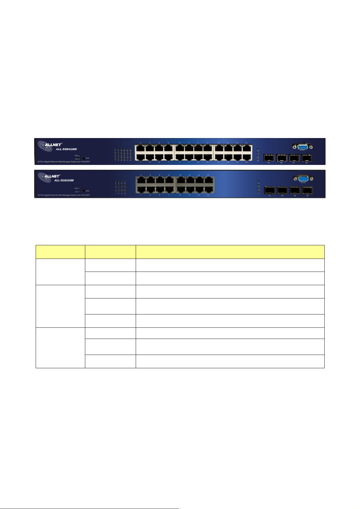
1.3 The Front Panel
The following figure shows the front panel of the switch.
LEDs Definition
This device provides extensive LEDs to show the activities on power, system and ports.
See the following description for your reference:
LED Status Operation
Steady Green The switch is powered on.
POWER
Off The switch is powered off.
Steady Green The switch is on and functioning properly
SYSTEM
Link/ACT
Blinking Green
Off The power is off or the system is not ready/malfunctioning.
Steady Green Valid port connection;.
Blinking Green
Off Port disconnected.
The switch is rebooting and performing self-diagnostic
tests.
Valid port connection and there is data
transmitting/receiving
The Reset Button
Reset the switch to its factory default configuration via the RESET button. Press the RESET
button for five seconds more and release. The switch automatically reboots and reloads its
factory configuration file. Press the RESET button for two seconds and release, the switch will
warm boot for hardware reset. The RESET button is on the front panel of the switch.
Console Port
This port is reserved for command-line interface (CLI) and RS232 firmware upgrade to use.
© ALLNET GmbH Computersysteme 2016 - Alle Rechte vorbehalten
Irrtum und Änderungen vorbehalten
7
Page 8

1.4 The Rear Panel
The following figure shows the rear panel of the switch:
Power Receptacle
To be compatible with the electric service standards around the world, the switch is designed
to afford the power supply in the range from 100 to 240 VAC, 50/60 Hz. Please make sure that
your outlet standard to be within this range.
To power on the switch, please plug the female end of the power cord firmly into the
receptacle of the switch, the other end into an electric service outlet. After the switch
powered on, please check if the power LED is lit for a normal power status.
1.5 Installation
Unpacking Information
The product package should include the following:
One 24G/16G+4SFP Gigabit Ethernet Smart Managed Switch
One power cord
Rubber foot and screws
Rack-mount brackets
One CD-ROM for user manual
Rack-mount Installation
Rack Mounting the Switch in the 19-inch rack:
Disconnect all cables from the switch before continuing.
Place the unit the right way up on a hard, flat surface with the front facing toward you.
Locate a mounting bracket over the mounting holes on one side of the unit.
Insert the screws and fully tighten with a suitable screwdriver.
Repeat the two previous steps for the other side of the unit.
Insert the unit into the 19" rack and secure with suitable screws (not provided).
Reconnect all cables.
Installing Network Cables
To make a valid connection and obtain the optimal performance, an appropriate cable that
© ALLNET GmbH Computersysteme 2016 - Alle Rechte vorbehalten
Irrtum und Änderungen vorbehalten
8
Page 9

corresponds to different transmitting/receiving speed is required. To choose a suitable cable,
please refer to the following table.
Media Speed Wiring
10Base-T: UTP category 3, 4, 5 cable (maximum 100m)
EIA/TIA-568 100Ω STP (maximum 100m)
100Base-TX: UTP category 5, 5e cable (maximum 100m)
EIA/TIA-568 100Ω STP (maximum 100m)
1000Base-T: UTP category 5e, 6 cable (maximum 100m)
EIA/TIA-568 100Ω STP (maximum 100m)
Network
Media(Cable)
10 Mbps
100 Mbps
1000 Mbps
© ALLNET GmbH Computersysteme 2016 - Alle Rechte vorbehalten
Irrtum und Änderungen vorbehalten
9
Page 10

Chapter 2 Getting Started
2.1 Web-based Management Interface (Web UI)
The Web UI supports all frequently used web browsers listed below:
Internet Explorer 8 and above
Firefox 20.0 and above
Chrome 23.0 and above
Safari 5.1.7 and above
2.2
Connect to switch Web Pag
1. To connect to the web server, input the IP of switch in the URL field of the browser.
2.
The default IP is 192.168.1.1 and default Subnet mask is 255.255.255.0
Type “http://”and the IP address of the switch (for example, the default management IP
3.
address is 192.168.1.1) in the Location or Address field. Press Enter.
es
The login screen appears. Enter the User Name and Password to login the configuration
4.
interface. They are both admin by default. You can select Remember my password to
remember the User Name and Password.
© ALLNET GmbH Computersysteme 2016 - Alle Rechte vorbehalten
Irrtum und Änderungen vorbehalten
10
Page 11
2.3 Graphic User Interface Overview
After the password authorization, the information page shows up. You may click on each
folder on the left column of each page to get access to each configuration page. The Graphic
User Interface is as follows:
ALL-SG8428M
ALL-SG8420M
© ALLNET GmbH Computersysteme 2016 - Alle Rechte vorbehalten
Irrtum und Änderungen vorbehalten
11
Page 12

In the navigation panel, click a main link to reveal a list of submenu links shown as the
following:
The following table describes the links in the navigation panel.
LINKS Submenu
System Information.
Logging Message
Status
Port – Statistics, Bandwidth Utilization
Link Aggregation
MAC Address Table
Network
IP Address
System Time
Port Setting
Port
Link Aggregation – Group, Port Setting, LACP
EEE
Jumbo Frame
VLAN - Create VLAN, VLAN Configuration, Membership,
VLAN
Port Setting
Voice VLAN - Property, Voice OUI
MAC Address Table
Dynamic Address
Static Address
Property
Spanning Tree
Port Setting
Statistics
Property
Port Setting
Discovery (LLDP)
Packet View
Local Information
Neighbor
Statistics
Multicast
Security
QoS
Diagnostics
Management
General – Property, Group Address, Router Port
IGMP Snooping – Property, Querier, Statistics
Management Access – Management VLAN, Management
Service
Protected Port
Storm Control
DoS – Property, Port Setting
General – Property, Queue Scheduling, CoS Mapping, DSCP
Mapping, IP Precedence Mapping
Rate Limit – Ingress/Egress Port, Egress Queue
Logging – Property, Remove Server
Mirroring
Ping
Copper Test
User Account
Firmware – Upgrade/Backup
Active Image
Configuration – Upgrade/Backup, Save Configuration,
Notification
© ALLNET GmbH Computersysteme 2016 - Alle Rechte vorbehalten
Irrtum und Änderungen vorbehalten
12
Page 13
Chapter 3 Status
Use the Status pages to view system information and status.
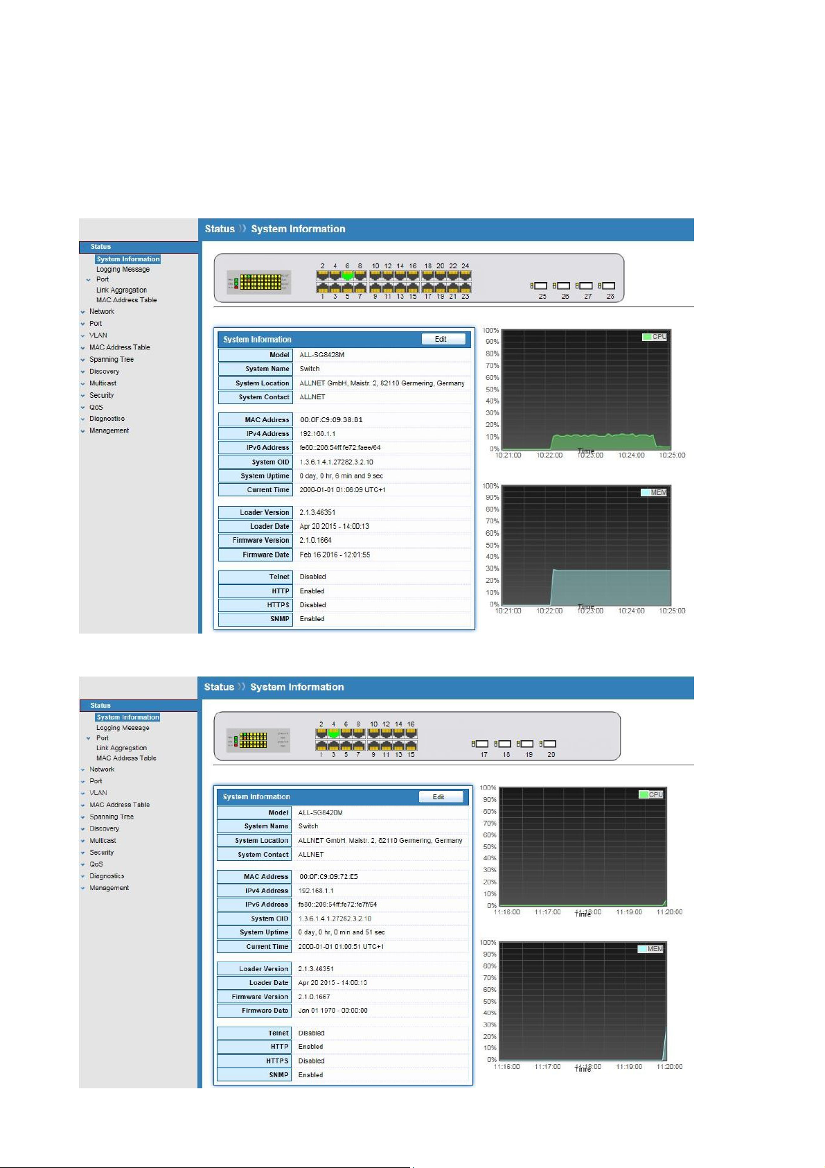
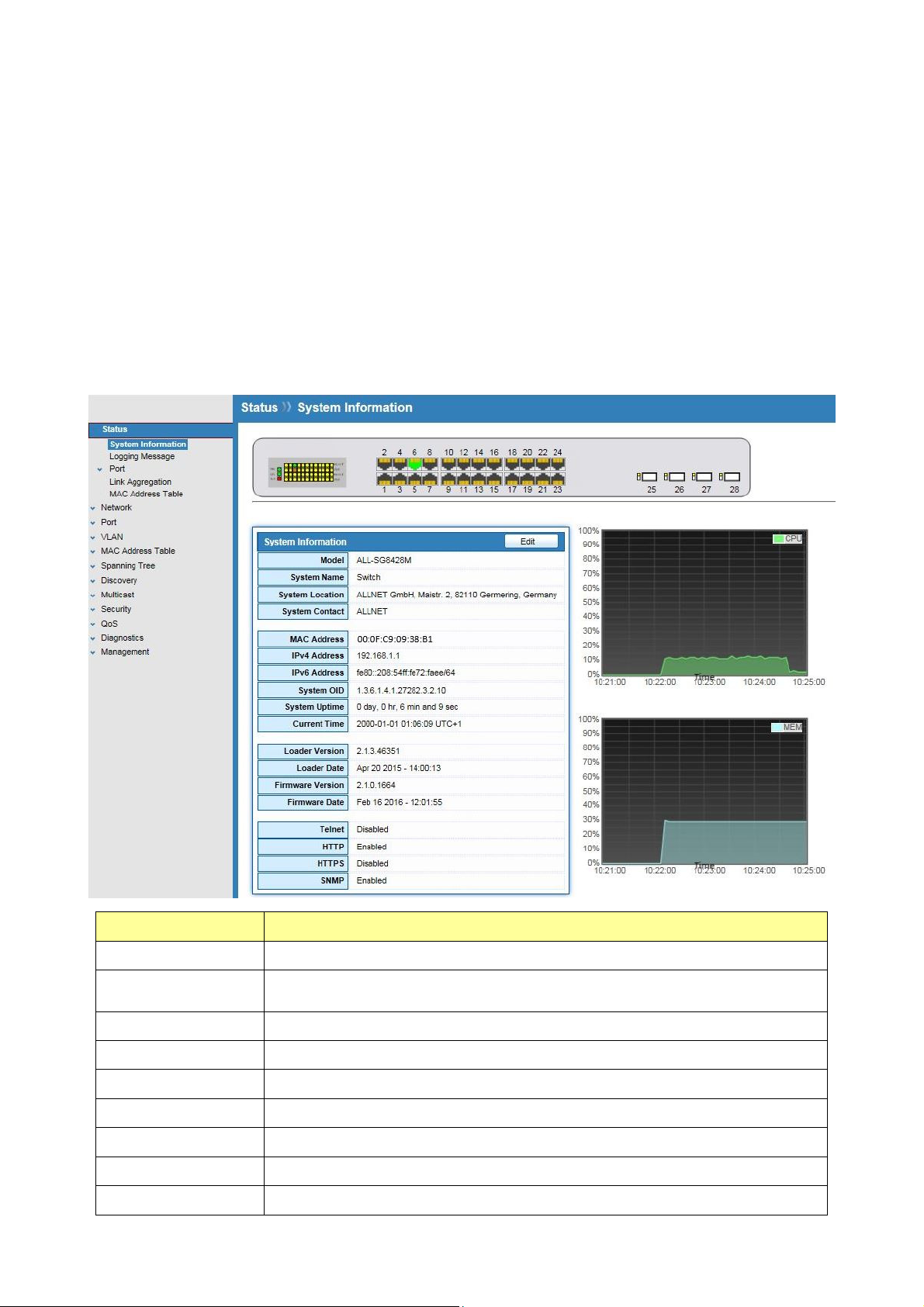
3.1 System Information
Click Status > System Information
This page shows switch panel, CPU utilization, Memory utilization and other system current
information. It also allows user to edit some system information.
Field Description
Model
System Name
System Location
System Contact
MAC Address
IPv4 Address
IPv6 Address
System OID
System Uptime
Model name of the switch
System name of the switch. This name will also use as CLI prefix of
each line
Location information of the switch
Contact information of the switch
Base MAC address of the switch
Current system IPv4 address
Current system IPv6 address
SNMP system object ID
Total elapsed time from booting
© ALLNET GmbH Computersysteme 2016 - Alle Rechte vorbehalten
Irrtum und Änderungen vorbehalten
13
Page 14
Current Time
Current system time
Loader Version
Loader Date
Firmware
Version
Firmware Date
Telnet
HTTP
HTTPS
SNMP
Boot loader image version
Boot loader image build date
Current running firmware image version
Current running firmware image build date
Current Telnet service enable/disable state
Current HTTP service enable/disable state
Current HTTPS service enable/disable state
Current SNMP service enable/disable state
Click “Edit” button on the table title to edit following system information.
Field Description
System Name
System Location
System Contact
System name of the switch. This name will also use as CLI prefix of
each line.
Location information of the switch.
Contact information of the switch.
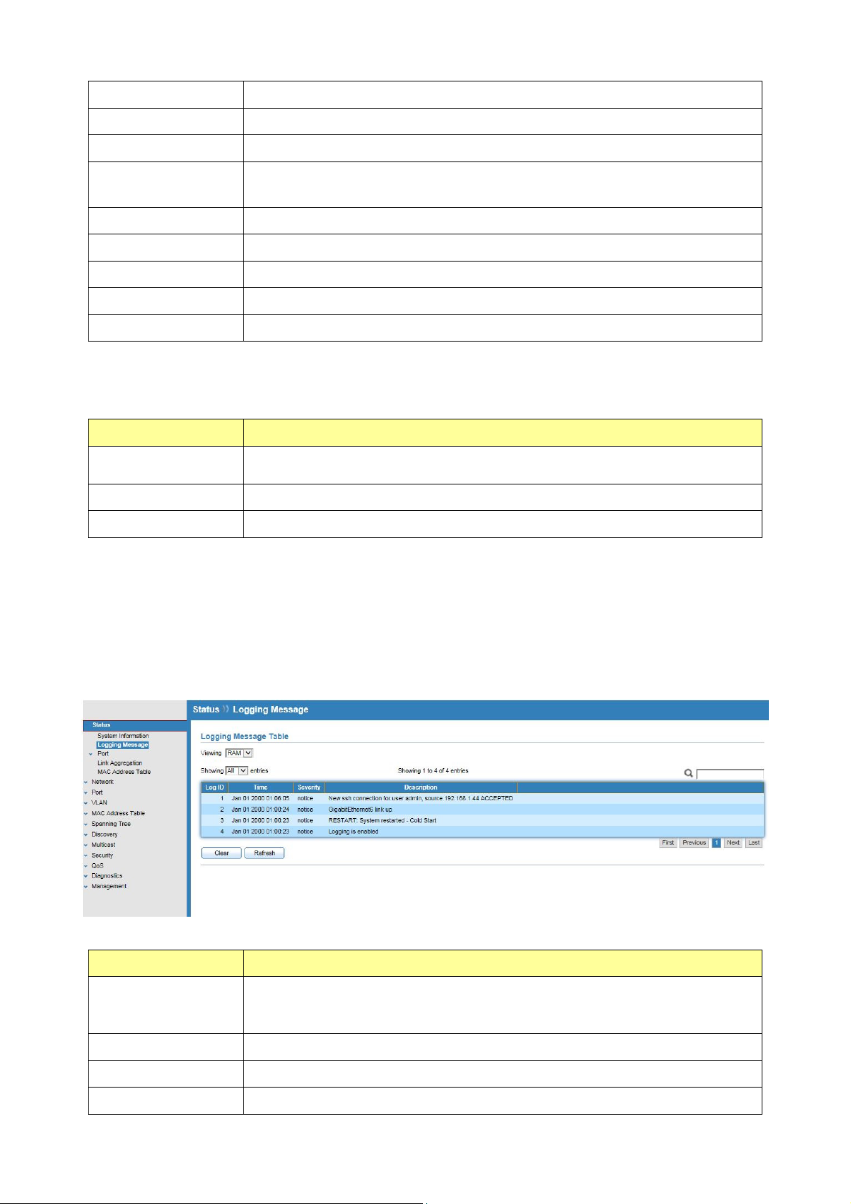
3.2 Logging Message
Click Status > Logging Message
This page shows logging messages stored on the RAM and Flash.
Field Description
The logging view including :
Viewing
Clear
RAM: Show the logging messages stored on the RAM
Flash: Show the logging messages stored on the Flash.
Clear the logging messages.
Refresh
Log ID
Refresh the logging messages.
The log identifier.
© ALLNET GmbH Computersysteme 2016 - Alle Rechte vorbehalten
Irrtum und Änderungen vorbehalten
14
Page 15
Time
The time stamp for the logging message.
Severity
Description
The severity for the logging message.
The description of logging message.
3.3 Port
The port configuration page displays port summary and status information.
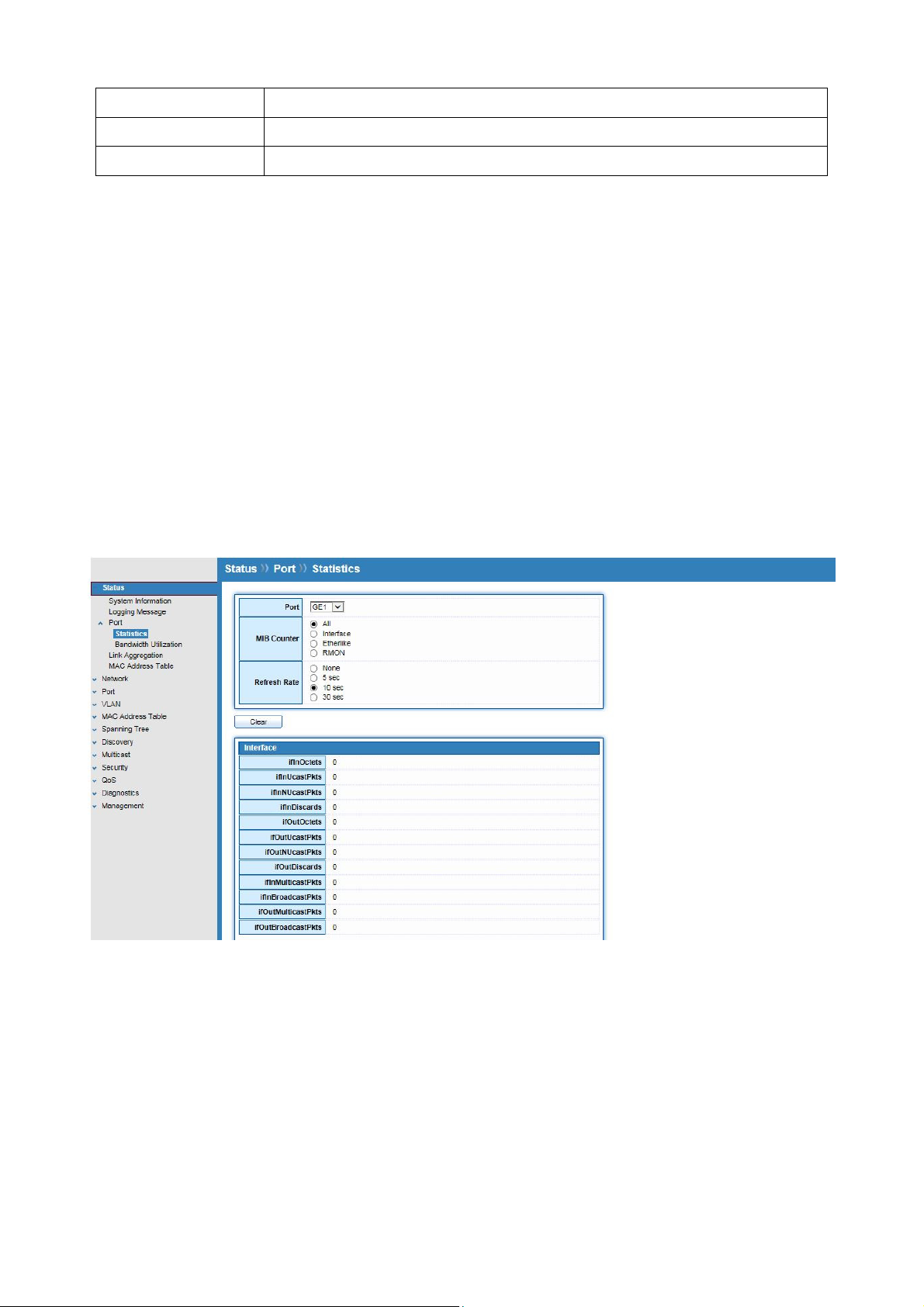
3.3.1 Statistics
Click Status > Port > Statistics
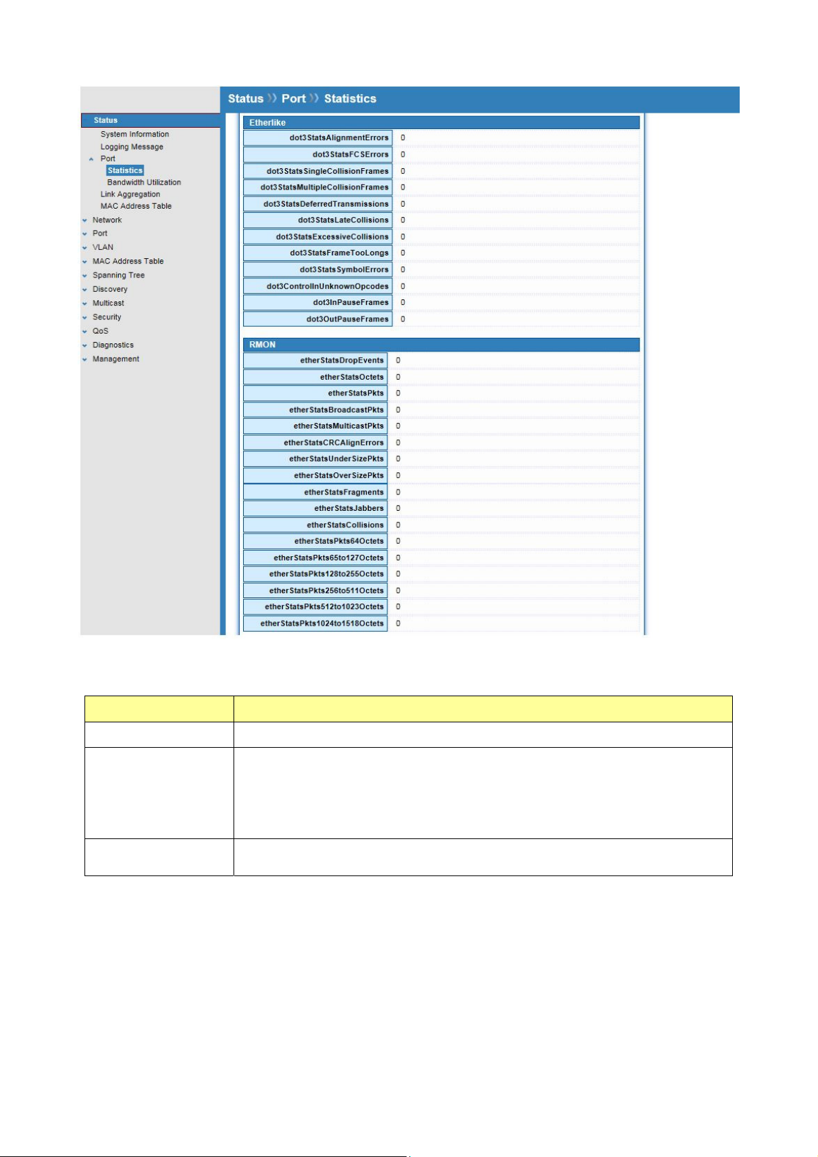
On this page user can get standard counters on network traffic from the interfaces,
Ethernet-like and RMON MIB. Interfaces and Ethernet-like counters display errors on the
traffic passing through each port. RMON counters provide a total count of different frame
types and sizes passing through each port.
© ALLNET GmbH Computersysteme 2016 - Alle Rechte vorbehalten
Irrtum und Änderungen vorbehalten
15
Page 16
The “Clear” button will clear MIB counter of current selected port.
Field Description
Port
Select one port to show counter statistics.
Select the MIB counter to show different count type
All: All counters.
MIB Counter
Interface: Interface related MIB counters
Etherlike: Ethernet-like related MIB counters
RMON : RMON related MIB counters
Refresh Rate
Refresh the web page every period of seconds to get new counter
of specified port.
3.3.2 Bandwidth Utilization
Click Status > Port > Bandwidth Utilization
This page allow user to browse ports’ bandwidth utilization in real time. This page will refresh
automatically in every refresh period.
© ALLNET GmbH Computersysteme 2016 - Alle Rechte vorbehalten
Irrtum und Änderungen vorbehalten
16
Page 17
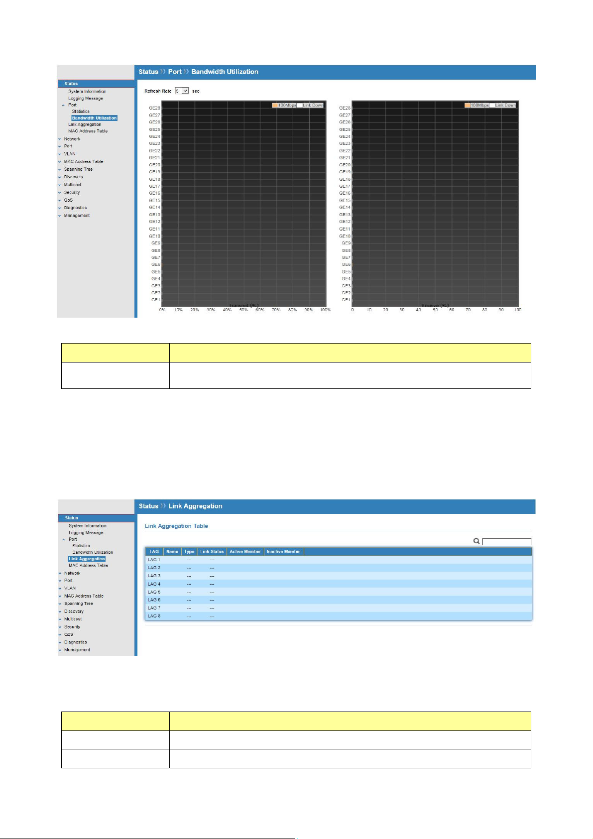
Field Description
Refresh Rate
Refresh the web page every period of second to get new
bandwidth utilization data.
3.4 Link Aggregation
Click Status > Link Aggregation
Display the Link Aggregation status of web page.
Field Description
Lag
Name
LAG Name.
LAG port description
© ALLNET GmbH Computersysteme 2016 - Alle Rechte vorbehalten
Irrtum und Änderungen vorbehalten
17
Page 18
Type
Link Status
The type of the LAG
Static: The group of ports assigned to a static LAG are always
active members.
LACP: The group of ports assigned to dynamic LAG are candidate
ports. LACP determines which candidate ports are active member
ports.
LAG port link status
Active Member
Inactive Member
Active member ports of the LAG
Inactive member ports of the LAG
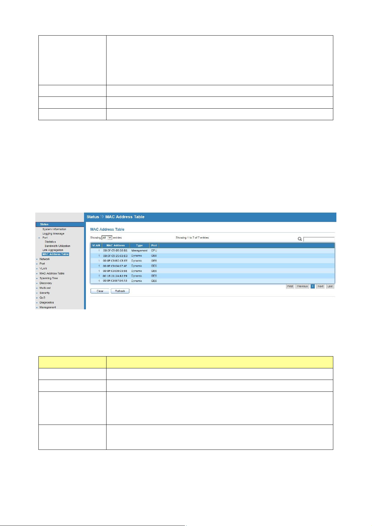
3.5 MAC Address Table
Click Status > MAC Address Table
The MAC address table page displays all MAC address entries on the switch including static
MAC address created by administrator or auto learned from hardware.
The “Clear” button will clear all dynamic entries and “Refresh” button will retrieve latest
MAC address entries and show them on page.
Field Description
VLAN
MAC Address
VLAN ID of the MAC address.
MAC address
The type of MAC address
Type
Management: DUT’s base MAC address for management purpose.
Static: Manually configured by administrator.
Dynamic: Auto learned by hardware.
The type of port
Port
CPU : DUT’s CPU port for management purpose
Other : Normal switch port
© ALLNET GmbH Computersysteme 2016 - Alle Rechte vorbehalten
Irrtum und Änderungen vorbehalten
18
Page 19
Chapter 4 Network
Use the Network pages to configure settings for the switch network interface and how the
switch connects to a remote server to get services.
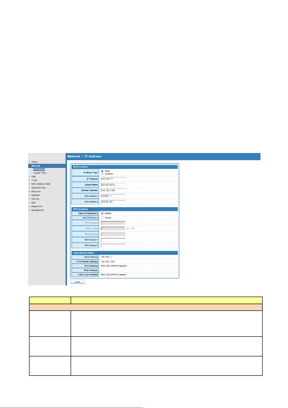
4.1 IP Address
Click Network > IP Address
Use the IP Setting screen to configure the switch IP address and the default gateway device.
The gateway field specifies the IP address of the gateway (next hop) for outgoing traffic.
The switch needs an IP address for it to be managed over the network. The factory default IP
address is 192.168.1.1. The subnet mask specifies the network number portion of an IP address.
The factory default subnet mask is 255.255.255.0.
Field Description
IPv4 Address Field
Address Type
IP Address
Subnet Mask
Select the address type of IP configuration
Static: Static IP configured by users will be used.
Dynamic: Enable DHCP to obtain IP information from a DHCP server
on the network.
Enter the IP address of your switch in dotted decimal notation for
example 192.168.1.1. If static mode is enabled, enter IP address in this
field.
Enter the IP subnet mask of your switch in dotted decimal notation for
example 255.255.255.0. If static mode is enabled, enter subnet mask in
this field.
© ALLNET GmbH Computersysteme 2016 - Alle Rechte vorbehalten
Irrtum und Änderungen vorbehalten
19
Page 20

Default
Gateway
DNS Server 1
DNS Server 2
IPv6 Address Field
Auto
Configuratio
n
DHCPv6
Client
IPv6 Address
IPv6 Prefix
Gateway
DNS Server 1
DNS Server 2
Operational Status
IPv4 Address
IPv4
Gateway
IPv6 Address
IPv6
Gateway
Link Local
Address
Specify the default gateway on the static configuration. The default
gateway must be in the same subnet with switch IP address configuration
If static mode is enabled, enter primary DNS server address in this field.
If static mode is enabled, enter secondary DNS server address in this field.
Select Enable or Disable the IPv6 auto configuration..
DHCPv6 client state.
Enable: Enable DHCPv6 client function.
Disable: Disable DHCPv6 client function
Specify the IPv6 address, when the IPv6 auto configuration and DHCPv6
client are disabled.
Specify the prefix for the IPv6 address, when the IPv6 auto configuration
and DHCPv6 client are disabled.
Specify the IPv6 default gateway, when the IPv6 auto configuration and
DHCPv6 client are disabled.
Specify the primary user-defined IPv6 DNS server configuration.
Specify the secondary user-defined IPv6 DNS server configuration.
The operational IPv4 address of the switch.
The operational IPv4 gateway of the switch.
The operational IPv6 address of the switch.
The operational IPv6 gateway of the switch.
The operational IPv6 link local address for the switch.
4.2 System Time
Click Network > System Time
This page allow user to set time source, static time, time zone and daylight saving settings.
Time zone and daylight saving takes effect both static time or time from SNTP server.
© ALLNET GmbH Computersysteme 2016 - Alle Rechte vorbehalten
Irrtum und Änderungen vorbehalten
20
Page 21
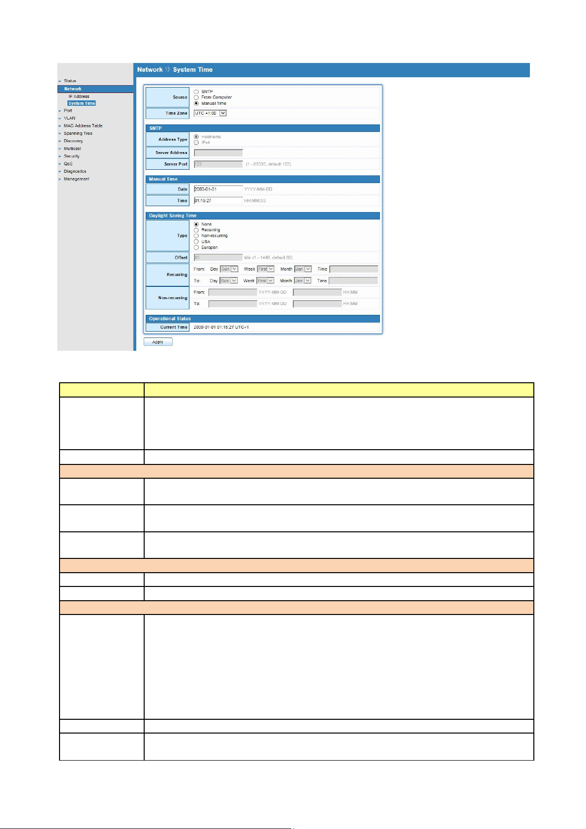
Field Description
Source
Select the time source
SNTP: Time sync from NTP server.
From Computer: Time set from browser host.
Manual Time: Time set by manually configure.
Time Zone
Select a time zone difference from listing district..
SNTP
Address Type
Select the address type of NTP server. This is enabled when time source is
SNTP.
Server
Address
Server Port
Input IPv4 address or hostname for NTP server. This is enabled when time
source is SNTP.
Input NTP port for NTP server. Default is 123. This is enabled when time
source is SNTP.
Manual Time
Date
Time
Input manual date. This is enabled when time source is manual.
Input manual time. This is enabled when time source is manual.
Daylight Saving Time
Type
Select the mode of daylight saving time.
Disable: Disable daylight saving time.
Recurring: Using recurring mode of daylight saving time.
Non-Recurring: Using non-recurring mode of daylight saving time.
USA : Using daylight saving time in the United States that starts on the
second Sunday of March and ends on the first Sunday of November
European: Using daylight saving time in the Europe that starts on the last
Sunday in March and ending on the last Sunday in October.
Offset
Recurring
From
Specify the adjust offset of daylight saving time.
Specify the starting time of recurring daylight saving time. This field
available when selecting “Recurring” mode.
© ALLNET GmbH Computersysteme 2016 - Alle Rechte vorbehalten
Irrtum und Änderungen vorbehalten
21
Page 22

Recurring To
Non-recurrin
g From
Non-recurrin
g To
Specify the ending time of recurring daylight saving time. This field
available when selecting “Recurring” mode.
Specify the starting time of non-recurring daylight saving time. This field
available when selecting “Non-Recurring” mode.
Specify the ending time of non-recurring daylight saving time. This field
available when selecting “Non-Recurring” mode.
© ALLNET GmbH Computersysteme 2016 - Alle Rechte vorbehalten
Irrtum und Änderungen vorbehalten
22
Page 23
Chapter 5 Port
Use the Port pages to configure settings for the switch port related features.
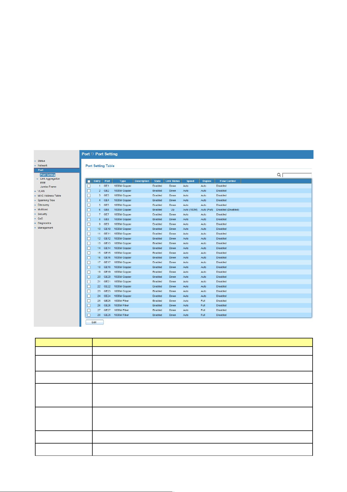
5.1 Port Setting
Click Port > Port Setting
This page shows port current status, and allow user to edit port configurations. Select port
entry and click “Edit” button to edit port configurations.
Field Description
Port
Type
Description
State
Link Status
Speed
Duplex
Port Name.
Allows you to Enable/Disable the port. When Enable is selected, the
port can forward the packets normally.
Port description
Port admin state.
Enabled: Enable the port.
Disabled: Disable the port.
Current port link status
Up: Port is link up.
Down: Port is link down.
Current port speed configuration and link speed status.
Current port duplex configuration and link duplex status.
© ALLNET GmbH Computersysteme 2016 - Alle Rechte vorbehalten
Irrtum und Änderungen vorbehalten
23
Page 24
Flow Control
Current port flow control configuration and link flow control status.
Note:
1. The switch can’t be managed through the disable port.
2. The switch might lose connection temporarily for the specific port (which connect to
the management PC) setting. If it happens, refresh WEB GUI can recover the
connection.
Edit Port Setting
Field Description
Port
Description
Selected Port list.
Port description
State
Link Status
Speed
Duplex
Port admin state.
Enabled: Enable the port.
Disabled: Disable the port.
Current port link status
Up: Port is link up.
Down: Port is link down.
Select the Port speed/duplex capabilities for the ports you need:
Auto: Auto-negotiation speed/ duplex with all capabilities.
Auto-10M: Auto speed with 10M ability only.
Auto-100M: Auto speed with 100M ability only.
Auto-1000M: Auto speed with 1000M ability only.
Auto-10M/100M: Auto speed with 10M/100M abilities.
10M: Force speed with 10M ability.
100M: Force speed with 100M ability.
1000M: Force speed with 1000M ability
Port duplex capabilities
Auto: Auto flow control ability.
Enabled: Enable flow control ability.
Disabled: Disable flow control ability.
5.2 Link Aggregation
Click Port > Link Aggregation
The Link Aggregation is used to combine a number of ports together to make a single
high-bandwidth data path, which can highly extend the bandwidth.
© ALLNET GmbH Computersysteme 2016 - Alle Rechte vorbehalten
Irrtum und Änderungen vorbehalten
24
Page 25
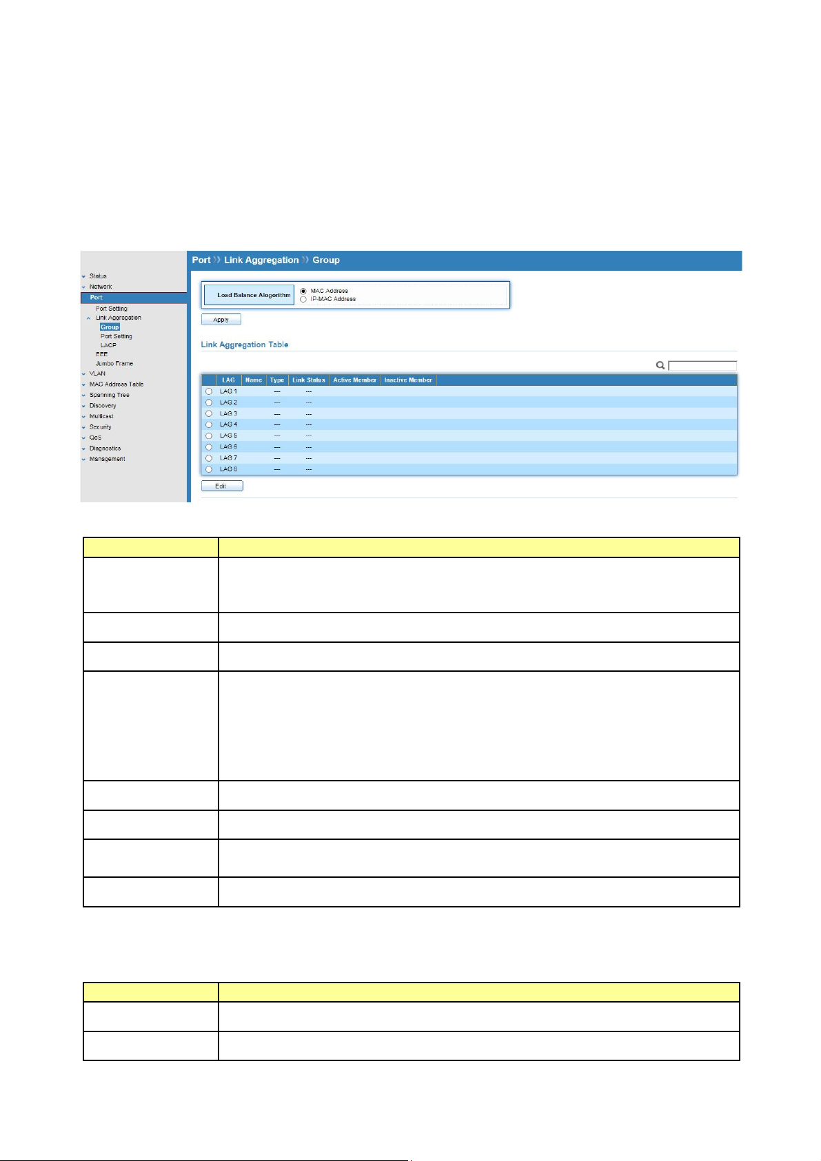
5.2.1 Trunk Group Setting
Click Port >Link Aggregation>Group
This page allow user to configure link aggregation group load balance algorithm and group
member.
Field Description
Load Balance
Algorithm
LAG load balance distribution algorithm.
Src-dst-mac: Based on MAC address
Src-dst-mac-ip: Based on MAC address and IP address
LAG
Name
Type
LAG (Link Aggregation Group) Name.
LAG port description
The type of the LAG.
Static: The group of ports assigned to a static LAG are always active
members.
LACP: The group of ports assigned to dynamic LAG are candidate
ports. LACP determines which candidate ports are active member
ports.
Link Status
Active Member
Inactive
LAG port link status.
Active member ports of the LAG.
Inactive member ports of the LAG.
Member
Flow Control
Current port flow control configuration and link flow control status.
Select Link Aggregation Table and click “Edit” button to edit LAG setting.
Edit LAG Group Setting
Field Description
LAG
Name
Selected LAG Group ID
LAG port description
© ALLNET GmbH Computersysteme 2016 - Alle Rechte vorbehalten
Irrtum und Änderungen vorbehalten
25
Page 26
Type
The type of the LAG.
Static: The group of ports assigned to a static LAG are always active
members.
LACP: The group of ports assigned to dynamic LAG are candidate
ports. LACP determines which candidate ports are active member
ports.
Member
Select available port to be LAG group member port.
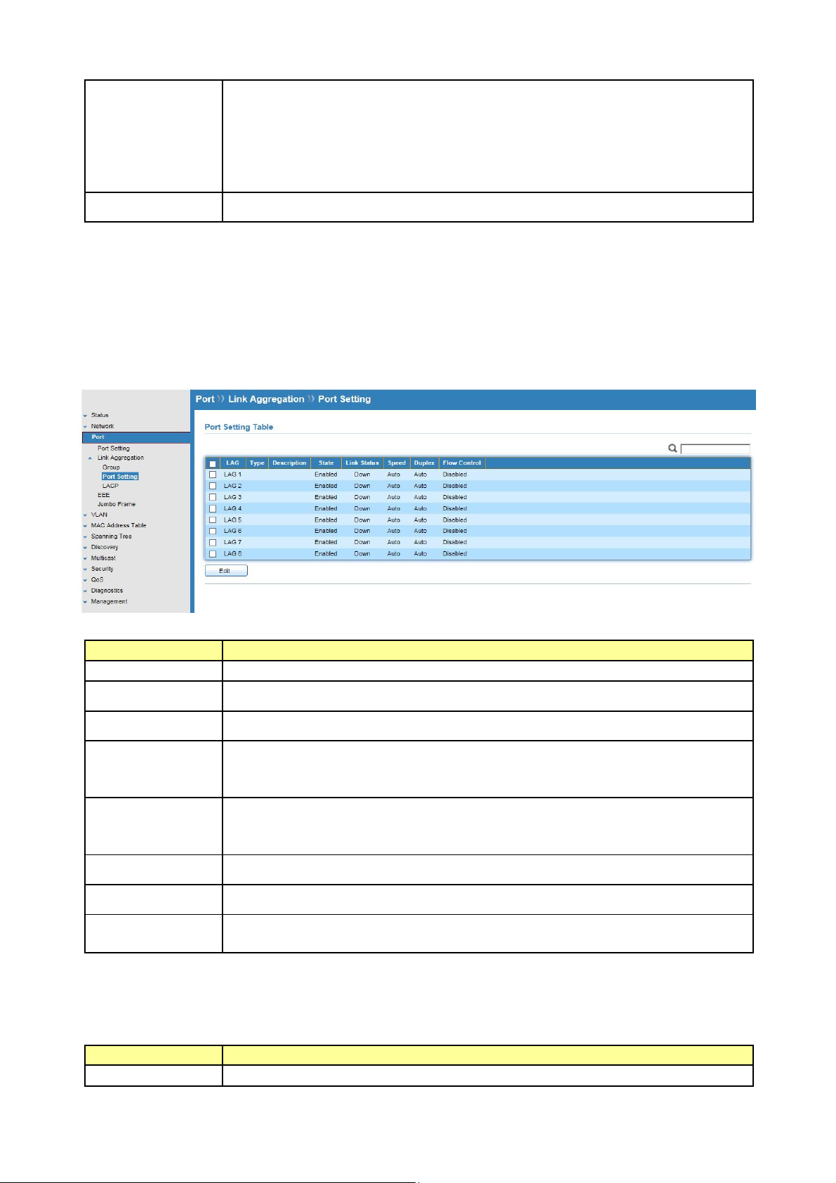
5.2.2 Port Setting
Click Port >Link Aggregation>Port Setting
This page shows LAG port current status and allows user to edit LAG port configurations.
Field Description
LAG
Type
Description
State
LAG Port Name
LAG Port media type
LAG port description
LAG Port admin state.
Enable : Enable the port
Disable : Disable the port
Link Status
Current LAG port link status.
Up : Port is link up
Down : Port is link down
Speed
Duplex
Flow Control
Current LAG port speed configuration and link speed status.
Current LAG port duplex configuration and link duplex status.
Current LAG port flow control configuration and link flow control
status.
Select Port Setting Table and click “Edit” button to edit port setting.
Edit LAG Port Setting
Field Description
Port
Selected port list
© ALLNET GmbH Computersysteme 2016 - Alle Rechte vorbehalten
Irrtum und Änderungen vorbehalten
26
Page 27
Description
Port description
State
Port admin state
Enable : Enable the port
Disable : Disable the port
Speed
Port speed capabilities.
Auto: Auto-negotiation speed/ duplex with all capabilities.
Auto-10M: Auto speed with 10M ability only.
Auto-100M: Auto speed with 100M ability only.
Auto-1000M: Auto speed with 1000M ability only.
Auto-10M/100M: Auto speed with 10M/100M abilities.
10M: Force speed with 10M ability.
100M: Force speed with 100M ability.
1000M: Force speed with 1000M ability
Flow Control
Port flow control.
Auto: Auto flow control by negotiation.
Enabled: Enable flow control ability.
Disabled: Disable flow control ability.
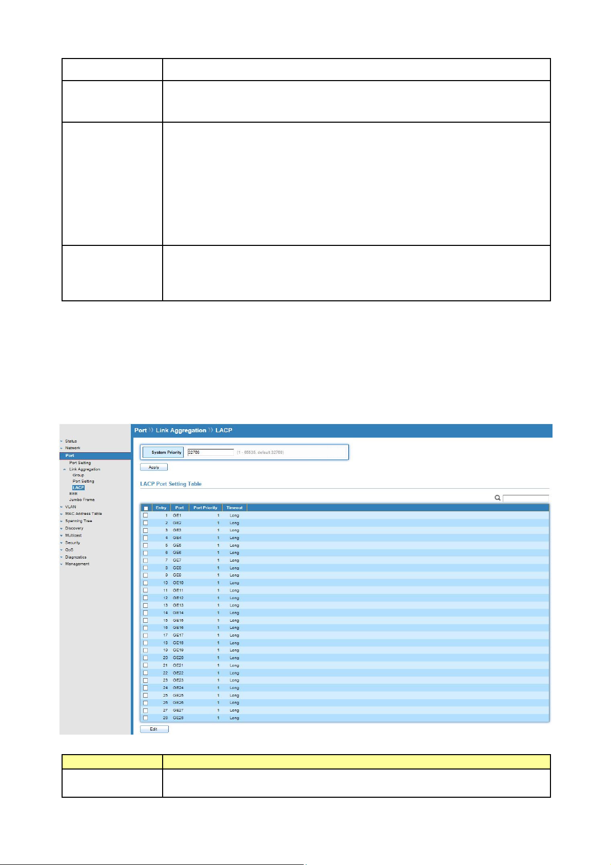
5.2.3 LACP
Click Port >Link Aggregation>LACP
This page allow user to configure LACP global and port configurations.
Field Description
System Priority
Configure the system priority of LACP. This decides the system priority
field in LACP PDU.
© ALLNET GmbH Computersysteme 2016 - Alle Rechte vorbehalten
Irrtum und Änderungen vorbehalten
27
Page 28
Port
Port Name.
Port Priority
Timeout
LACP priority value of the port.
The periodic transmissions type of LACP PDUs.
Long: Transmit LACP PDU with slow periodic (30s).
Short: Transmit LACP PDU with fast periodic (1s).
Select ports and click “Edit” button to edit port configuration.
Edit LACP Port Setting
Field Description
Port
Port Priority
Timeout
Selected port list.
Enter the LACP priority value of the port.
The periodic transmissions type of LACP PDUs.
Long: Transmit LACP PDU with slow periodic (30s).
Short: Transmit LACP PDU with fast periodic (1s).
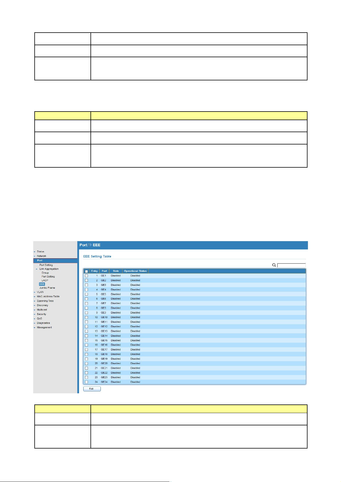
5.3 EEE
Click Port > EEE
This page allows user to enable or disable EEE (Energy Efficient Ethernet) function.
Field Description
Port
State
Port Name.
Port EEE admin state.
Enable: EEE is enabled
Disable: EEE is disabled.
© ALLNET GmbH Computersysteme 2016 - Alle Rechte vorbehalten
Irrtum und Änderungen vorbehalten
28
Page 29
Operational
Status
Port EEE operational status.
Enable: EEE is operating
Disable: EEE is no operating
Select EEE and click “Edit” button to edit EEE configuration.
Edit EEE Setting
Field Description
Port
Selected port list.
State
Port EEE admin state.
Enable: Enable EEE
Disable: Disabled EEE.
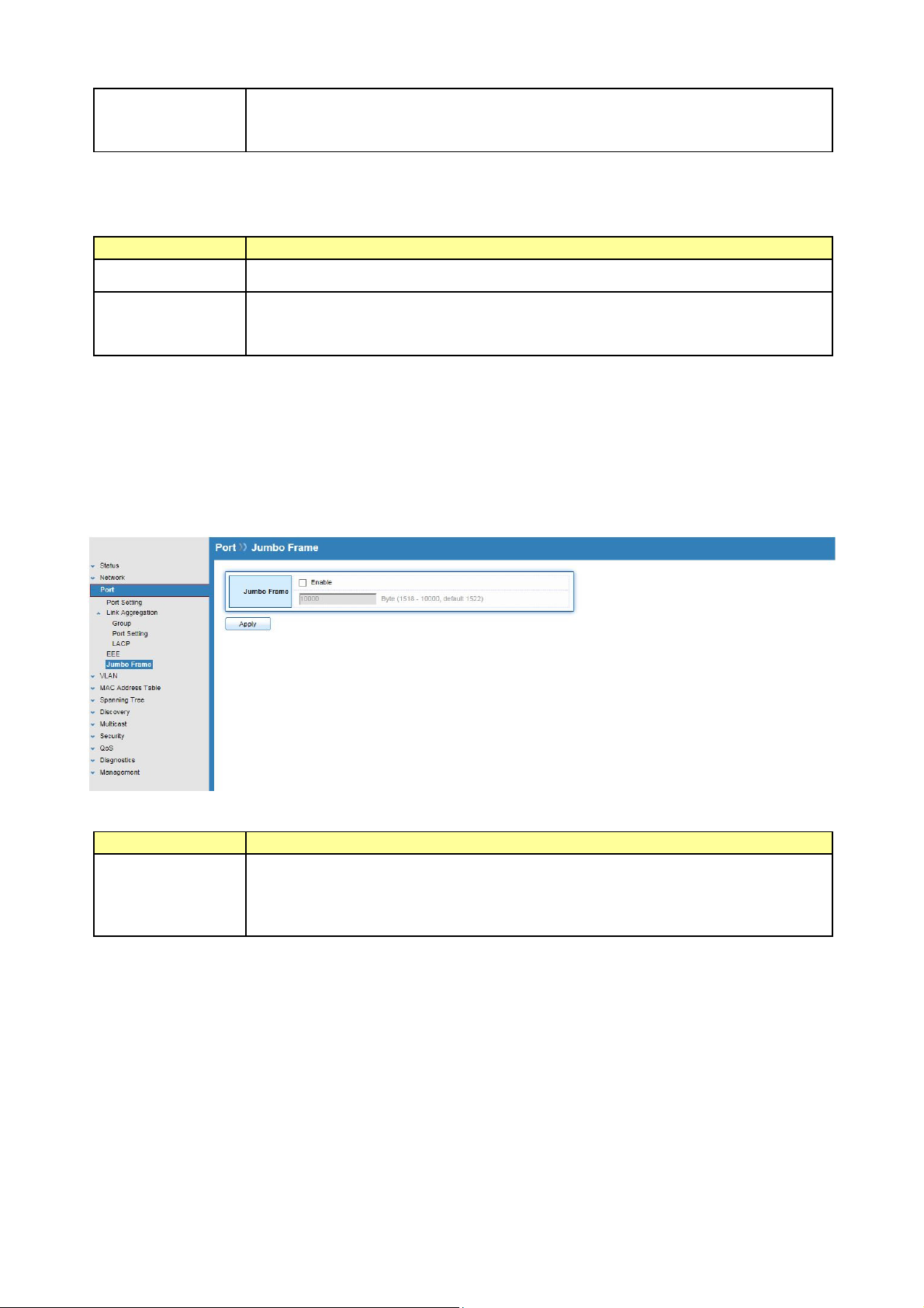
5.3 Jumbo Frame
Click Port > Jumbo Frame
This page allows user to configure switch jumbo frame size.
Field Description
Jumbo Frame
Enable or Disable jumbo frame.
When jumbo frame is enabled, switch max frame size is allowed to
configure. (from 1518 to 10000)
When jumbo frame is disabled, default frame size 1522 will be used.
© ALLNET GmbH Computersysteme 2016 - Alle Rechte vorbehalten
Irrtum und Änderungen vorbehalten
29
Page 30
Chapter 6 VLAN
A virtual local area network (VLAN) is a group of hosts with a common set of requirements
that communicate as if they were attached to the same broadcast domain, regardless of their
physical location. A VLAN has the same attributes as a physical local area network (LAN), but it
allows for end stations to be grouped together even if they are not located on the same
network switch. VLAN membership can configured through software instead of physically
relocating devices or connections.
.
6.1 VLAN
Use the VLAN pages to configure settings of VLAN and all VLAN-related protocol.
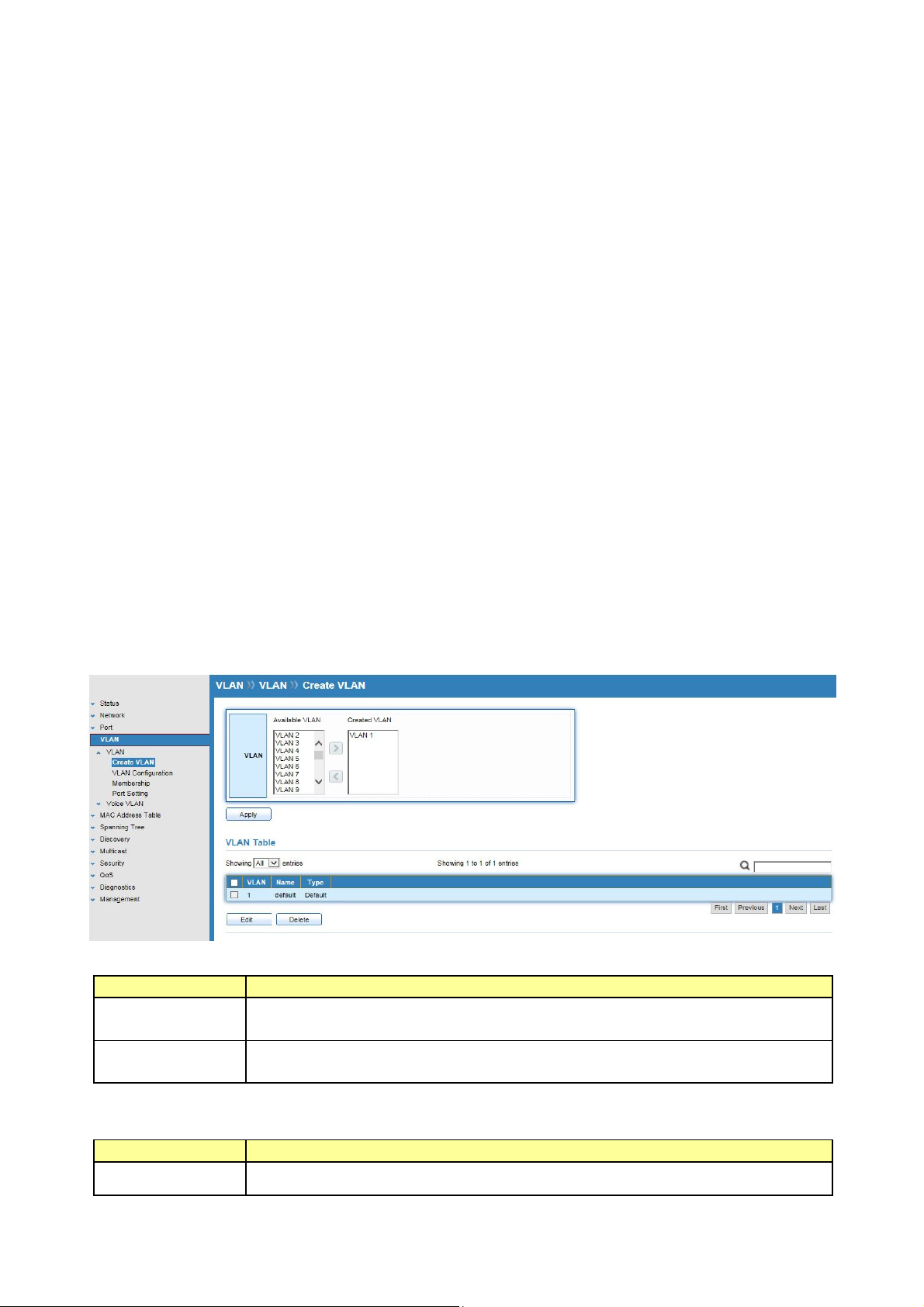
6.1.1 Create VLAN
Click VLAN > VLAN > Create VLAN
This page allows user to add or delete VLAN ID entries and browser all VLAN entries that add
statically or dynamic learned by GVRP. Each VLAN entry has a unique name, user can edit
VLAN name in edit page.
Field Description
Available
VLAN
Created VLAN
Click “Edit” button to edit VLAN name
Field Description
Name
VLAN has not created yet.
Select available VLANs from left box then move to right box to add.
VLAN had been created.
Select created VLANs from right box then move to left box to delete.
Input VLAN name.
© ALLNET GmbH Computersysteme 2016 - Alle Rechte vorbehalten
Irrtum und Änderungen vorbehalten
30
Page 31

6.1.2 VLAN Configuration
Click VLAN > VLAN > VLAN Configuration
This page allow user to configure the membership for each port of selected VLAN.
Field Description
VLAN
Port
Mode
Membership
Select specified VLAN ID to configure VLAN configuration.
Display the interface of port entry.
Display the interface VLAN mode of port.
Select the membership for this port of the specified VLAN ID.
Forbidden: Specify the port is forbidden in the VLAN.
Excluded: Specify the port is excluded in the VLAN.
Tagged: Specify the port is tagged member in the VLAN.
Untagged: Specify the port is untagged member in the VLAN.
PVID
Display if it is PVID of interface.
© ALLNET GmbH Computersysteme 2016 - Alle Rechte vorbehalten
Irrtum und Änderungen vorbehalten
31
Page 32

6.1.3 Membership
Click VLAN > VLAN > Membership
This page allow user to view membership information for each port and edit membership for
specified interface.
Field Description
Port
Mode
Administrative
VLAN
Operational
VLAN
Display the interface of port entry.
Display the interface VLAN mode of port.
Display the administrative VLAN list of this port.
Display the operational VLAN list of this port. Operational VLAN
means the VLAN status that really runs in device. It may different to
administrative VLAN.
Click “Edit” button to edit VLAN membership
Field Description
Port
Mode
Membership
Display the interface of port entry.
Display the VLAN mode of interface.
Select VLANs of left box and select one of following membership then
move to right box to add membership. Select VLANs of right box then
move to left box to remove membership. Tagging membership may
© ALLNET GmbH Computersysteme 2016 - Alle Rechte vorbehalten
Irrtum und Änderungen vorbehalten
32
Page 33

not choose in differ VLAN port mode.
Forbidden: Set VLAN as forbidden VLAN.
Excluded: Set option is always disabled.
Tagged: Set VLAN as tagged VLAN.
Untagged: Set VLAN as untagged VLAN.
PVID: Check this checkbox to select the VLAN ID to be the port-based
VLAN ID for this port. PVID may auto select or can’t select in differ
settings.
6.1.4 Port Setting
Click VLAN > VLAN > Port Setting
This page allow user to configure port VLAN settings such as VLAN port mode, PVID etc… The
attributes depend on different VLAN port mode.
Field Description
Port
Mode
PVID
Accept Frame
Display the interface.
Display the VLAN mode of port.
Display the Port-based VLAN ID of port.
Display accepted frame type of port.
Type
Ingress
Display ingress filter status of port
Filtering
© ALLNET GmbH Computersysteme 2016 - Alle Rechte vorbehalten
Irrtum und Änderungen vorbehalten
33
Page 34

Click “Edit” button to edit VLAN port setting
Field Description
Port
Display the interface of port entry.
Mode
Select the VLAN mode of the interface.
Hybrid: Support all functions as defined in IEEE802.1Q specification.
Access: Accepts only untagged frames and join an untagged VLAN.
Trunk: An untagged member of one VLAN at most, and is a tagged
member of zero or more VLANs.
PVID
Specify the port-based VLAN ID (1~4094). It’s only available with
hybrid and Trunk mode.
Accept Frame
Type
Ingress
Filtering
Specify the acceptable-frame-type of the specified interfaces. It’s only
available with Hybrid mode.
Specify the status of ingress filtering. It’s only available with Hybrid
mode.
6.2 Voice VLAN
6.2.1 Property
Click VLAN > Voice VLAN > Property
This page allow user to configure global and per interface setting of voice VLAN.
© ALLNET GmbH Computersysteme 2016 - Alle Rechte vorbehalten
Irrtum und Änderungen vorbehalten
34
Page 35

Field Description
State
Set checkbox to enable or disable voice VLAN function.
VLAN
Cos/802.1p
Select Voice VLAN ID. Voice VLAN ID cannot be default VLAN.
Select a value of VPT. Qualified packets will use this VPT value as inner
priority.
Remarking
Set checkbox to enable or disable 1p remarking. If enabled, qualified
packets will be remark by this value.
Aging Time
Input value of aging time. Default is 1440 minutes. A voice VLAN entry
will be age out after this time if without any packet pass through.
Field Description
Port
State
Mode
QoS Policy
Display port entry
Display enable/disable status of interface.
Display voice VLAN mode.
Display voice VLAN remark will effect which kind of packet
Click “Edit” button to edit Property Port.
Field Description
Port
Display selected port to be edited.
State
Mode
Set checkbox to enable/disable voice VLAN function of interface.
Select port voice VLAN mode.
Auto: Voice VLAN auto detect packets that match OUI table and add
received port into voice VLAN ID tagged member.
Manual: User need add interface to VLAN ID tagged member
manually.
QoS Policy
Select port QoS Policy mode
Voice Packet: QoS attributes are applied to packets with OUIs in the
source MAC address.
All: QoS attributes are applied to packets that are classified to the
Voice VLAN.
6.2.2 Voice OUI
Click VLAN > Voice VLAN > Voice OUI
This page allow user to add, edit or delete OUI MAC addresses. Default has 8 pre-defined OUI
MAC.
© ALLNET GmbH Computersysteme 2016 - Alle Rechte vorbehalten
Irrtum und Änderungen vorbehalten
35
Page 36

Field Description
OUI
Display OUI MAC address.
Description
Display description of OUI entry.
Click “Add” or “Edit” buttons to edit Voice OUI.
Field Description
OUI
Description
Input OUI MAC address, Can’t be edited in edit dialog.
Input description of the specified MAC address to the voice VLAN OUI
table.
© ALLNET GmbH Computersysteme 2016 - Alle Rechte vorbehalten
Irrtum und Änderungen vorbehalten
36
Page 37

Chapter 7 MAC Address Table
Use the MAC Address Table pages to show dynamic MAC table and configure settings for
static MAC entries.
7.1 Dynamic Address
Click MAC Address Table > Dynamic Address
Configure the aging time of the dynamic address.
Field Description
Aging Time
The time in seconds that an entry remains in the MAC address table. Its
valid range is from 10 to 630 seconds, and the default value is 300
seconds.
7.2 Static Address
Click MAC Address Table > Static Address
To display the static MAC address.
© ALLNET GmbH Computersysteme 2016 - Alle Rechte vorbehalten
Irrtum und Änderungen vorbehalten
37
Page 38

Field Description
MAC Address
The MAC address to which packets will be statically fowarded.
VLAN
Port
Specify the VLAN to show or clear MAC entries.
Interface or port number.
© ALLNET GmbH Computersysteme 2016 - Alle Rechte vorbehalten
Irrtum und Änderungen vorbehalten
38
Page 39

Chapter 8 Spanning Tree Protocol (STP)
The Spanning Tree Protocol (STP) is a network protocol that ensures a loop-free topology for
any bridged Ethernet local area network.
8.1 Property
Click STP > Property
Configure and display STP property configuration.
Field Description
State
Operation
Mode
Path Cost
Enable/Disable the STP on the switch.
Specify the STP operation mode.
STP: Enable the Spanning Tree (STP) operation.
RSTP: Enable the Rapid Spanning Tree (RSTP) operation.
Specify the path cost method.
Long: Specifies that the default port path costs are within the range :
1~200,000,000.
Short: Specifies that the default port path costs are within the range :
1~65,535.
© ALLNET GmbH Computersysteme 2016 - Alle Rechte vorbehalten
Irrtum und Änderungen vorbehalten
39
Page 40

BPDU Handling
Specify the BPDU forward method when the STP is disabled.
Filtering: Filter the BPDU when STP is disabled.
Flooding: Flood the BPDU when STP is disabled.
Priority
Specify the bridge priority. The valid range is from 0 to 61440, and the
value should be the multiple of 4096. It ensures the probability that
the switch is selected as the root bridge, and the lower value has the
higher priority for the switch to be selected as the root bridge of the
topology.
Hello Time
Specify the STP hello time in second to broadcast its hello message to
other bridge by Designated Ports. Its valid range is from 1 to 10
seconds.
Max Age
Specify the time interval in seconds for a switch to wait the
configuration messages, without attempting to redefine its own
configuration.
Forward Delay
Specify the STP forward delay time, which is the amount of time that a
port remains in the Listening and Learning states before it enters the
Forwarding state. Its valid range is from 4 to 10 seconds.
TX Hold Count
Specify the tx-hold-count used to limit the maximum numbers of
packets transmission per second. The valid range is from 1 to 10.
STP operational status
Field Description
Bridge
Bridge identifier of the switch.
Identifier
Designated
Bridge identifier of the designated root bridge.
Root Identifier
Root Port
Root Path Cost
Topology
Operational root port of the switch.
Operational root path cost.
Numbers of the topology changes.
Change Count
Last Topology
The last time for the topology change.
Change
© ALLNET GmbH Computersysteme 2016 - Alle Rechte vorbehalten
Irrtum und Änderungen vorbehalten
40
Page 41

8.2 Port Setting
Click STP > Port Setting
Configure and display STP port settings.
Field Description
Port
State
Path Cost
Priority
Operation
Edge
Operational
Point-to-Point
Port Role
Port State
Designated
Bridge
Designated
Port ID
Specify the interface ID or the list of interface IDs.
The operational state on the specified port.
STP path cost on the specified port.
STP priority on the specified port.
The operational edge port on the specified port.
The operational edge point-to-point status on the specified port.
The current port role on the specified port. The possible values are:
“Disabled”, “Master”, “Root”, “Designated”, “Alternative”, and
“Backup”
The current port state on the specified port. The possible values are:
“Disabled”, “Discarding”, “Learning”, and “Forwarding”.
The bridge ID of the designated bridge.
The designated port ID on the switch.
© ALLNET GmbH Computersysteme 2016 - Alle Rechte vorbehalten
Irrtum und Änderungen vorbehalten
41
Page 42

Designated
The path cost of the designated port on the switch.
Cost
STP port setting buttons
Field Description
Protocol
Migration
Check
Edit STP port setting
Field Description
State
Restart the Spanning Tree Protocol (STP) migration process
(re-negotiate with its neighborhood) on the specific interface.
Enable/Disable the STP on the specified port
Path Cost
Priority
Edge Port
Specify the STP path cost on the specified port.
Specify the STP priority on the specified port.
Specify the edge mode.
Enable : Force to true state (as link to a host)
Disable : Force to false state (as link to a bridge)
In the edge mode, the interface would be put into the Forwarding
state immediately upon link up. If the edge mode is enabled for the
interface and there are BPDUs received on the interface, the loop
might be occurred in the short time before the STP state change.
Point-to-Point
Specify the Point-to-Point port configuration:
Auto: The state is depended on the duplex setting of the port.
Enable: Force to true state.
Disable: Force to false state.
8.3 Statistics
Click STP > Statistics
To display STP statistics
Bridge Protocol Data Units (BPDUs) are frames that contain information about
the Spanning tree protocol (STP). Switches send BPDUs using a unique MAC address from
its origin port and a multicast address as destination MAC (01:80:C2:00:00:00, or
01:00:0C:CC:CC:CD for Per VLAN Spanning Tree). For STP algorithms to function, the switches
need to share information about themselves and their connections. What they share are
bridge protocol data units (BPDUs). BPDUs are sent out as multicast frames to which only
other layer 2 switches or bridges are listening. If any loops (multiple possible paths between
switches) are found in the network topology, the switches will co-operate to disable a port or
ports to ensure that there are no loops; that is, from one device to any other device in the
layer 2 network, only one path can be taken.
© ALLNET GmbH Computersysteme 2016 - Alle Rechte vorbehalten
Irrtum und Änderungen vorbehalten
42
Page 43

Field Description
Refresh Rate
The option to refresh the statistics automatically.
Receive BPDU
(Config)
Receive BPDU
(TCN)
Transmit BPDU
The counts of the received CONFIG BPDU.
The counts of the received TCN BPDU.
The counts of the transmitted CONFIG BPDU.
© ALLNET GmbH Computersysteme 2016 - Alle Rechte vorbehalten
Irrtum und Änderungen vorbehalten
43
Page 44

(Config)
Transmit BPDU
(TCN)
The counts of the transmitted TCN BPDU.
Field Description
Clear
View
Clear the statistics for the selected interfaces.
View the statistics for the interface.
View STP Port Statistics.
Field Description
Refresh Rate
Clear
The option to refresh the statistics automatically.
Clear the statistics for the selected interfaces.
© ALLNET GmbH Computersysteme 2016 - Alle Rechte vorbehalten
Irrtum und Änderungen vorbehalten
44
Page 45

Chapter 9 Discovery
9.1 LLDP
The Link Layer Discovery Protocol (LLDP) is a vendor-neutral link layer protocol in
the Internet Protocol Suite used by network devices for advertising their identity, capabilities,
and neighbors on an IEEE 802 local area network, principally wired Ethernet. The LLDP is a
one-way protocol; there are no request/response sequences. Information is advertised by
stations implementing the transmit function, and is received and processed by stations
implementing the receive function. The LLDP category contains LLDP and LLDP-MED pages.
9.1.1 Property
Click Discovery > LLDP > Property
To display LLDP Property Setting web page.
Field Description
State
LLDP Handling
Enable/Disable LLDP protocol on this switch
Select LLDP PDU handling action to be filtered, bridging or flooded
when LLDP is globally disabled.
Filtering: Deletes the packet.
Bridging: (VLAN-aware flooding) Forwards the packet to all VLAN
members.
Flooding: Forwards the packet to all ports.
© ALLNET GmbH Computersysteme 2016 - Alle Rechte vorbehalten
Irrtum und Änderungen vorbehalten
45
Page 46

TLV Advertise
Interval
Holdtime
Multiplier
Reinitialization
Delay
Transmit Delay
9.1.2 Port Setting
Select the interval at which frames are transmitted. The default is 30
seconds, and the valid range is 5~32767 seconds.
Select the multiplier on the transmit interval to assign to TTL (range
2~10, default=4).
Select the delay before a re-initialization (range 1~10 seconds,
default=2).
Select the delay after an LLDP frame is sent (range 1~8191 seconds,
default=3).
Click Discovery > LLDP > Port Setting
To display LLDP Port Setting.
© ALLNET GmbH Computersysteme 2016 - Alle Rechte vorbehalten
Irrtum und Änderungen vorbehalten
46
Page 47

To Edit LLDP port setting web page, select the port which to set, click button Edit.
Field Description
Port
Select specified port or all ports to configure LLDP state.
Mode
Optional TLV
802.1 VLAN
Name
9.1.3 Packet View
Select the transmission state of LLDP port interface.
Disable: Disable the transmission of LLDP PDUs.
RX Only: Receive LLDP PDUs only.
TX Only: Transmit LLDP PDUs only.
Normal: Transmit and receive LLDP PDUs both.
Select the LLDP optional TLVs to be carried (multiple selection is
allowed).
System Name
Port Description
System Description
System Capability
802.3 MAC-PHY
802.3 Link Aggregation
802.3 Maximum Frame Size
Management Address
802.1 PVID
Select the VLAN Name ID to be carried (multiple selection is allowed).
Click Discovery > LLDP > Packet View
To display LLDP Overloading.
© ALLNET GmbH Computersysteme 2016 - Alle Rechte vorbehalten
Irrtum und Änderungen vorbehalten
47
Page 48

Field Description
Port
Port Name
In-Use (Bytes)
Available
(Bytes)
Operational
Total number of bytes of LLDP information in each packet.
Total number of available bytes left for additional LLDP information in
each packet.
Overloading or not
Status
If need detail information, select the port, then click detail.
Field Description
Port
Mandatory
TLVs
802.3 TLVs
Port Name
Total mandatory TLV byte size.
Status is sent or overloading.
Total 802.3 TLVs byte size.
Status is sent or overloading.
© ALLNET GmbH Computersysteme 2016 - Alle Rechte vorbehalten
Irrtum und Änderungen vorbehalten
48
Page 49

Optional TLVs
Total Optional TLV byte size.
Status is sent or overloading.
802.1 TLVs
Total 802.1 TLVs byte size.
Status is sent or overloading.
Total
Total number of bytes of LLDP information in each packet.
9.1.4 Local Information
Click Discovery > LLDP > Local Information
To display LLDP Local Device.
Use the LLDP Local Information to view LLDP local device information.
© ALLNET GmbH Computersysteme 2016 - Alle Rechte vorbehalten
Irrtum und Änderungen vorbehalten
49
Page 50

Field Description
Chassis ID
Type of chassis ID, such as the MAC address.
Subtype
Chassis ID
Identifier of chassis. Where the chassis ID subtype is a MAC address,
the MAC address of the switch is displayed.
System Name
Name of switch
System
Description of the switch.
Description
Capabilities
Primary functions of the device, such as Bridge, WLAN AP, or Router.
Supported
Capabilities
Primary enabled functions of the device.
Enabled
Port ID
Type of the port identifier that is shown.
Subtype
LLDP Status
LLDP Tx and Rx abilities.
Click “detail” button on the page to view detail information of the selected port.
9.1.5 Neighbor
Click Discovery > LLDP > Neighbor
To display LLDP Remote Device.
Use the LLDP Neighbor page to view LLDP neighbors information.
Field Description
Local Port
Chassis ID
Number of the local port to which the neighbor is connected.
Type of chassis ID (for example, MAC address)
Subtype
Chassis ID
Port ID
Identifier of the 802 LAN neighboring device’s chassis.
Type of the port identifier that is shown.
Subtype
Port ID
Identifier of port.
© ALLNET GmbH Computersysteme 2016 - Alle Rechte vorbehalten
Irrtum und Änderungen vorbehalten
50
Page 51

System Name
Published name of the switch.
Time to Live
Time interval in seconds after which the information for this neighbor
is deleted.
Click “detail” to view selected neighbor detail information.
9.1.6 Statistics
Click Discovery > LLDP > Statistics
To display LLDP Statistics status.
The Link Layer Discovery Protocol (LLDP) Statistics page displays summary and per-port
information for LLDP frames transmitted and received on the switch.
© ALLNET GmbH Computersysteme 2016 - Alle Rechte vorbehalten
Irrtum und Änderungen vorbehalten
51
Page 52

Field Description
Insertions
The number of times the complete set of information advertised by a
particular MAC Service Access Point (MSAP) has been inserted into
tables associated with the remote systems.
Deletions
The number of times the complete set of information advertised by
MSAP has been deleted from tables associated with the remote
systems.
Drops
The number of times the complete set of information advertised by
MSAP could not be entered into tables associated with the remote
systems because of insufficient resources.
Age Outs
The number of times the complete set of information advertised by
MSAP has been deleted from tables associated with the remote system
because the information timeliness interval has expired.
Port
Interface or port number.
Transmit
Frame Total
Receive Frame
Total
Receive Frame
Discard
Receive Frame
Error
Receive TLV
Discard
Receive TLV
Unrecognized
Neighbor
Timeout
Number of LLDP frames transmitted on the corresponding port/
Number of LLDP frames received by this LLDP agent on the
corresponding port, while the LLDP agent is enabled.
Number of LLDP frames discarded for any reason by the LLDP agent on
the corresponding port.
Number of invalid LLDP frames received by the LLDP agent on the
corresponding port, while the LLDP agent is enabled.
Number of TLVs of LLDP frames discarded for any reason by the LLDP
agent on the corresponding port.
Number of TLVs of LLDP frames that are unrecognized while the LLDP
agent is enabled.
Number of age out LLDP frames.
© ALLNET GmbH Computersysteme 2016 - Alle Rechte vorbehalten
Irrtum und Änderungen vorbehalten
52
Page 53

Chapter 10 Multicast
10.1 General
Use the General pages to configure setting of IGMP snooping property and group and router
setting function.
10.1.1 Property
Click Multicast > General > Property
This page allow user to set multicast forwarding method and unknown multicast action.
Field Description
Unknown
Multicast
Action
IPv4
Set the unknown multicast action
Drop: drop the unknown multicast data.
Flood: flood the unknown multicast data.
Router port: forward the unknown multicast data to router port.
Set the IPv4 multicast forward method.
MAC-VID: forward method dmac+vid.
DIP-VID: forward method dip+vid.
10.1.2 Group Address
Click Multicast > General > Group Address
To display Multicast General Group web page.
© ALLNET GmbH Computersysteme 2016 - Alle Rechte vorbehalten
Irrtum und Änderungen vorbehalten
53
Page 54

This page allow user to browse all multicast groups that dynamic learned or statically added.
Field Description
VLAN
The VLAN ID of group.
Group Address
Member
Type
Life(Sec)
The group IP address.
The member ports of group.
The type of group. Static or Dynamic.
The life time of this dynamic group.
Click “Add” to add Group Address.
Field Description
VLAN
Group Address
Member
The VLAN ID of group.
The group IP address.
The member ports of group.
Available Port : Optional port member
Selected Port : Selected port member
Click “Edit” to edit Group Address.
Field Description
VLAN
The VLAN ID of group.
Group Address
Member
The group IP address.
The member ports of group.
Available Port : Optional port member
Selected Port : Selected port member
10.1.3 Router Port
Click Multicast > General > Router Port
To display Multicast router port table web page.
© ALLNET GmbH Computersysteme 2016 - Alle Rechte vorbehalten
Irrtum und Änderungen vorbehalten
54
Page 55

This page browse all router port information.
Field Description
VLAN
The VLAN ID router entry.
Member
Life (Sec)
Router Port member.
The expiry time of the router entry.
10.2 IGMP Snooping
Use the IGMP Snooping pages to configure setting of IGMP snooping function.
10.2.1 Property
Click Multicast > IGMP Snooping > Property
To display IGMP Snooping global setting and VLAN setting web page.
This page allow user to configure global settings of IGMP snooping and configure specific
VLAN settings of IGMP Snooping.
© ALLNET GmbH Computersysteme 2016 - Alle Rechte vorbehalten
Irrtum und Änderungen vorbehalten
55
Page 56

Field Description
State
Set the enabling status of IGMP Snooping functionality
Enable: If Checked Enable IGMP Snooping, else is Disabled IGMP
Snooping.
Version
Set the IGMP Snooping version
IGMPv2: Only support process IGMP v2 packet.
IGMPv3: Support v3 basic and v2.
Report
Suppression
Set the enabling status of IGMP v2 report suppression.
Enable: If Checked Enable IGMP Snooping v2 report suppression, else
Disable the report suppression function.
VLAN
The IGMP entry VLAN ID.
Operation
The enable status of IGMP Snooping VLAN functionality.
Status
Router Port
The enabling status of IGMP Snooping router port auto learning
Auto Learn
Query
Robustness
Query Interval
Query Max
Response
The Query Robustness allows tuning for the expected packet lose on a
subnet.
The interval of query to send general query.
In Membership Query Messages, it specifies the maximum allowed
time before sending a responding report in units of 1/10 second.
Interval
Last Member
Query count
Last Member
Query Interval
Immediate
Leave
The count that Querier-switch sends Group-Specific Queries when it
receives a Leave Group message for a group.
The interval that Querier-switch sends Group-Specific Queries when it
receives a Leave Group message for a group.
The immediate leave status of the group will immediate leave when
receive IGMP Leave message.
Click “Edit” to edit VLAN Setting.
Field Description
VLAN
The selected VLAN List
State
Router Port
Auto Learn
Immediate
Leave
Query
Robustness
Query Interval
Query Max
Response
Interval
Last Member
Set the enabling status of IGMP Snooping VLAN functionality
Enable: If Checked Enable IGMP Snooping router VLAN, else is
Disabled IGMP Snooping VLAN.
Set the enabling status of IGMP Snooping router port learning.
Enable: If Checked Enable learning router port by query and PIM,
DVRMP, else Disable the learning router port.
Immediate Leave the group when receive IGMP Leave message.
Enable: If Checked Enable immediate leave, else Disable immediate
leave.
The Admin Query Robustness allows tuning for the expected packet
loss on a subnet.
The Admin interval of querier to send general query.
The Admin query max response interval, In Membership Query
Messages, it specifies the maximum allowed time before sending a
responding report in units of 1/10 second.
The Admin last member query count that Querier-switch sends
© ALLNET GmbH Computersysteme 2016 - Alle Rechte vorbehalten
Irrtum und Änderungen vorbehalten
56
Page 57

Query Counter
Group-Specific Queries when it receives a Leave Group message for a
group.
Last Member
Query Interval
The Admin last member query interval that Querier-switch sends
Group-Specific Queries when it receives a Leave Group message for a
group.
Operational Status.
Field Description
Status
Operational IGMP Snooping status, must both IGMP Snooping global
and IGMP Snooping enable the status will be enable.
Query
Operational Query Robustness.
Robustness
Query Interval
Operational Query Interval.
Query Max
Operational Query Max Response Interval.
Response
Interval
Last Member
Operational Last Member Query Count.
Query Counter
Last Member
Operational Last Member Query Interval.
Query Interval
10.2.2 Querier
Click Multicast > IGMP Snooping > Querier
To display IGMP Snooping Querier setting web page.
This page allow user to configure querier setting on specific VLAN of IGMP Snooping.
Field Description
VLAN
State
IGMP Snooping querier entry VLAN ID.
The IGMP Snooping querier Admin State.
© ALLNET GmbH Computersysteme 2016 - Alle Rechte vorbehalten
Irrtum und Änderungen vorbehalten
57
Page 58

Operational
The IGMP Snooping querier operational status.
Status
Querier
The IGMP Snooping querier operational version.
Version
Querier IP
The operational querier IP address on the VLAN.
Click “Edit” to edit IGMP Snooping Querier.
Field Description
VLAN
The selected Edit IGMP Snooping querier VLAN list.
State
Set the enabling status of IGMP Querier Election on the chose VLANs.
Enabled: If checked Enable IGMP Querier, else Disable IGMP Querier.
Version
Set the query version of IGMP Querier Election on the chose VLANs.
IGMPv2: Querier version 2
IGMPv3: Querier version 3. (IGMP Snooping version should be
IGMPv3)
10.2.3 Statistics
Click Multicast > IGMP Snooping > Statistics
This page allow user to display IGMP Snooping Statistics and clear IGMP Snooping statistics.
© ALLNET GmbH Computersysteme 2016 - Alle Rechte vorbehalten
Irrtum und Änderungen vorbehalten
58
Page 59

Receive Packet
Field Description
Total
Total RX IGMP packet, include IPv4 multicast data to CPU.
Valid
InValid
Other
Leave
Report
General Query
Special Group
The valid IGMP Snooping process packet.
The invalid IGMP Snooping process packet.
The ICMP protocol is not 2, and is not IPv4 multicast data packet.
IGMP leave packet.
IGMP join and report packet.
IGMP general query packet
IGMP special group general query packet
Query
Source-specific
IGMP special source and group general query packet
Group Query
Transmit Packet
Field Description
Leave
Report
General Query
IGMP leave packet
IGMP join and report packet
IGMP general query packet includes querier transmit general query
packet.
Special Group
Query
Source-specific
IGMP special group query packet include querier transmit special
group query packet.
IGMP special source and group general query packet.
Group Query
© ALLNET GmbH Computersysteme 2016 - Alle Rechte vorbehalten
Irrtum und Änderungen vorbehalten
59
Page 60

Chapter 11 Security
Use the security pages to configure setting for the switch security features.
11.1 Management Access
Use the Management Access pages to configure setting of management access..
11.1.1 Management VLAN
Click Security > Management Access > Management VLAN
This page allow user to change Management VLAN connection.
Field Description
Management
VLAN
Select management VLAN in option list.
Management connection, such as http, https, SNMP etc.., has the same
VLAN of management VLAN are allow connecting to device. Others
will be dropped.
11.1.2 Management Service
Click Security > Management Access > Management Service
This page allow user to change management services related configurations.
© ALLNET GmbH Computersysteme 2016 - Alle Rechte vorbehalten
Irrtum und Änderungen vorbehalten
60
Page 61

Field Description
Management
Service
Management Service admin state.
Telnet: Connect CLI through Telnet.
HTTP: Connect Web UI through HTTP.
HTTPS: Connect Web UI through HTTPS.
SNMP: Manage switch through SNMP.
Session
Timeout
Set session timeout minutes for user access to user interface. O minute
means never timeout.
11.2 Protected Port
Click Security > Protected Port
This page allow user to configure protected port setting to prevent the selected ports from
communication with each other. Protected port is only allowed to communicate with
unprotected port. In other words, protected port is not allowed to communicate with another
protected port.
© ALLNET GmbH Computersysteme 2016 - Alle Rechte vorbehalten
Irrtum und Änderungen vorbehalten
61
Page 62

Field Description
Port
Port Name
State
Port protected admin state.
Protected: Port is protected.
Unprotected: Port is unprotected.
Click “Edit” to edit the protected port.
Field Description
Port
State
Selected port list
Port protected admin state.
Protected: Enable protecting function.
Unprotected: Disable protecting function.
11.3 Storm Control
Click Security > Storm Control
To display Storm Control global setting web page.
© ALLNET GmbH Computersysteme 2016 - Alle Rechte vorbehalten
Irrtum und Änderungen vorbehalten
62
Page 63

Field Description
Unit
Select the unit of storm control
Packet/Sec : storm control rate calculates by packet-based
Kbits/Sec : storm control rate calculates by octet-based
IFG
Select the rate calculates w/o preamble & IFG (20 bytes)
Excluded: exclude preamble & IFG (20 bytes) when count ingress
storm control rate.
Included: include preamble & IFG (20 bytes) when count ingress storm
control rate.
Click “Edit” to edit the storm control port setting web page.
Field Description
Port
Select the setting ports
State
Select the state of setting.
Enable: Enable the storm control function.
Broadcast Enable: Enable the storm control function of broadcast packet.
Value of storm control rate, Unit: pps (packet per-second, range
1~262143) or Kbps (Kbits per-second, range16~1000000) depends on
global mode setting.
Unknown
Multicast
Enable: Enable the storm control function of unknown multicast
packet.
Value of storm control rate, Unit: pps (packet per-second, range
1~262143) or Kbps (Kbits per-second, range16~1000000) depends on
© ALLNET GmbH Computersysteme 2016 - Alle Rechte vorbehalten
Irrtum und Änderungen vorbehalten
63
Page 64

global mode setting.
Unknown
Unicast
Enable: Enable the storm control function of unknown unicast
packet.
Value of storm control rate, Unit: pps (packet per-second, range
1~262143) or Kbps (Kbits per-second, range16~1000000) depends on
global mode setting.
Action
Select the state of setting.
Drop: Packets exceed storm control rate will be dropped.
Shutdown: Port will be shutdown when packets exceed storm control
rate.
11.4 DoS
A Denial of Service (DoS) attack is a hacker attempt to make a device unavailable to its users.
DoS attacks saturate the device with external communication requests, so that it cannot
respond to legitimate traffic. These attacks usually lead to a device CPU overload.
The DoS protection feature is a set of predefined rules that protect the network from
malicious attacks. The DoS Security Suite Setting enables activating the security suite.
11.4.1 Property
Click Security > DoS > Property
To display DoS Global Setting web page.
© ALLNET GmbH Computersysteme 2016 - Alle Rechte vorbehalten
Irrtum und Änderungen vorbehalten
64
Page 65

Field Description
POD
Avoids ping of death attack.
Land
Drops the packets if the source IP address is equal to the destination IP
address.
UDP Blat
Drops the packets if the UDP source port equals to the UDP
destination port.
TCP Blat
Drops the packages if the TCP source port is equal to the TCP
destination port.
DMAC=SMAC
Drops the packets if the destination MAC address is equal to the
source MAC address.
Null Scan
Drops the packets with NULL scan.
Attack
X-Mas Scan
Attack
TCP SYN-FIN
Drops the packets if the sequence number is zero, and the FIN, URG
and PSH bits are set.
Drops the packets with SYN and FIN bits set.
Attack
TCP SYN-RST
Drops the packets with SYN and RST bits set.
Attack
ICMP Flagment
Drops the fragmented ICMP packets.
© ALLNET GmbH Computersysteme 2016 - Alle Rechte vorbehalten
Irrtum und Änderungen vorbehalten
65
Page 66

TCP-SYN(SPORT
Drops SYN packets with sport less than 1024.
<1024)
TCP Fragment
Drops the TCP fragment packets with offset equals to one.
(Offset=1)
Ping Max Size
Specify the maximum size of the ICMPv4/ICMPv6 ping packets. The
valid range is from 0 to 65535 bytes, and the default value is 512 bytes.
IPv4 Ping Max
Size
IPv6 Ping Max
Size
TCP Min Hdr
Size
Checks the maximum size of ICMP ping packets, and drops the packets
larger than the maximum packet size.
Checks the maximum size of ICMPv6 ping packets, and drops the
packets larger than the maximum packet size
Checks the minimum TCP header and drops the TCP packets with the
header smaller than the minimum size. The length range is from 0 to
31 bytes, and default length is 20 bytes.
IPv6 Min
Flagment
Checks the minimum size of IPv6 fragments, and drops the packets
smaller than the minimum size. The valid range is from 0 to 65535
bytes, and default value is 1240 bytes.
Smurf Attack
Avoid smurf attack. The length range of the netmask is from 0 to 323
bytes, and default length is 0 bytes.
11.4.2 Port Setting
Click Security > DoS > Port Setting
To configure and display the state of DoS protection for interfaces.
© ALLNET GmbH Computersysteme 2016 - Alle Rechte vorbehalten
Irrtum und Änderungen vorbehalten
66
Page 67

Field Description
Port
Interface or port number.
State
Enable/Disable the DoS protection on the interface.
Chapter 12 QoS
QoS (Quality of Service) functions to provide different quality of service for various network
applications and requirements and optimize the bandwidth resource distribution so as to
provide a network service experience of a better quality.
12.1 General
Use the QoS general pages to configure setting for general purpose.
12.1.1 Property
Click QoS > General > Property
To display QoS property web page.
© ALLNET GmbH Computersysteme 2016 - Alle Rechte vorbehalten
Irrtum und Änderungen vorbehalten
67
Page 68

Field Description
State
Set checkbox to enable/disable QoS.
Trust Mode
Select QoS trust mode.
CoS: Traffic is mapped to queues based on the CoS field in the VLAN
tag, or based on the per-port default CoS value (if there is no VLAN
tag on the incoming packet), the actual mapping of the CoS to queue
can be configured on port setting dialog.
DSCP: All IP traffic is mapped to queues based on the DSCP field in the
IP header. The actual mapping of the DSCP to queue can be
configured on the DSCP mapping page. If traffic is not IP traffic, it is
mapped to the best effort queue.
CoS-DSCP: Uses the trust CoS mode for non-IP traffic and trust DSCP
mode for IP traffic.
IP Precedence: Traffic is mapped to queues based on the IP
precedence. The actual mapping of the IP precedence to queue can be
configured on the IP Precedence mapping page.
Field Description
Port
CoS
Trust
Port name
Port default CoS priority value for the selected ports.
Port trust state
Enable: Traffic will follow trust mode in global setting.
Disable: Traffic will always use best efforts.
Remarking
(CoS)
Port CoS remarking admin state.
Enable: CoS remarking is enabled
Disable: CoS remarking is disabled
Remarking
(DSCP)
Port DSCP remarking admin state.
Enable: DSCP remarking is enabled
Disable: DSCP remarking is disabled
Remarking
(IP Precedence)
Port IP Precedence remarking admin state.
Enable: IP Precedence remarking is enabled
Disable: IP Precedence remarking is disabled
Click “Edit” to edit the QoS port setting.
Field Description
Port
CoS
Trust
Remarking
(CoS)
Remarking
Select port list
Set default CoS priority value for the selected ports.
Set checkbox to enable/disable port trust state.
Set checkbox to enable/disable port CoS remarking.
Set checkbox to enable/disable port DSCP remarking.
(DSCP)
Remarking
Set checkbox to enable/disable port IP Precedence remarking.
(IP Precedence)
© ALLNET GmbH Computersysteme 2016 - Alle Rechte vorbehalten
Irrtum und Änderungen vorbehalten
68
Page 69

12.1.2 Queue Scheduling
Click QoS > General > Queue Scheduling
To display Queue Scheduling web page.
The switch supports eight queues for each interface. Queue number 8 is the highest priority
queue. Queue number 1 is the lowest priority queue. There are two ways of determining how
traffic in queues is handled, Strict Priority (SP) and Weighted Round Robin (WRR).
Strict Priority (SP) : Egress traffic from the highest priority queue is transmitted first. Traffic
from the lower queues is processed only after the highest queue has been transmitted, which
provide the highest level of priority of traffic to the highest numbered queue.
Weighted Round Robin (WRR) : In WRR mode the number of packets sent from the queue is
proportional to the weight of the queue (the higher the weight, the more frames are sent).
The queuing mode can be selected on the Queue page. When the queuing mode is by Strict
Priority, the priority sets the order in which queues are serviced, starting with queue_8 (the
highest priority queue) and going to the next lower queue when each queue is completed.
When the queuing mode is Weighted Round Robin, queues are serviced until their quota has
been used up and then another queue is serviced. It is also possible to assign some of the
lower queues to WRR, while keeping some of the higher queues in Strict Priority. In this case
traffic for the SP queues is always sent before traffic from the WRR queues. After the SP
queues has been emptied, traffic from the WRR queues is forwarded. (The relative portion
from each WRR queue depends on its weight).
Field Description
Queue
Queue ID to configure
Strict Priority
WRR
Set queue to strict priority type
Set queue to Weight Round Robin type.
© ALLNET GmbH Computersysteme 2016 - Alle Rechte vorbehalten
Irrtum und Änderungen vorbehalten
69
Page 70

Weight
If the queue type is WRR, set the queue weight for the queue.
WRR
Percentage of WRR queue bandwidth.
Bandwidth
12.1.3 CoS Mapping
Click QoS > General > CoS Mapping
To display CoS Mapping web page.
The CoS to Queue table determines the egress queues of the incoming packets based on the
802.1p priority in their VLAN tags. For incoming untagged packets, the 802.1p priority will be
the default CoS/802.1p priority assigned to the ingress ports.
Use the Queues to CoS table to remark the CoS/802.1p priority for egress traffic from each
queue.
Field Description
CoS
Queue
CoS value
Select queue ID for the CoS value
Field Description
Queue
CoS
Queue ID
Select CoS value for the queue ID.
12.1.4 DSCP Mapping
Click QoS > General > DSCP Mapping
© ALLNET GmbH Computersysteme 2016 - Alle Rechte vorbehalten
Irrtum und Änderungen vorbehalten
70
Page 71

To display DSCP Mapping web page.
The DSCP to Queue table determines the egress queues of the incoming IP packets based on
their DSCP values. The original VLAN Priority Tag (VPT) of the packet is unchanged.
Use the Queues to DSCP page to remark DSCP value for egress traffic from each queue.
Field Description
DSCP
Queue
DSCP value
Select Queue ID for DSCP value.
Field Description
Queue
DSCP
Queue ID
Select DSCP value for Queue ID.
12.1.5 IP Precedence Mapping
Click QoS > General > IP Precedence Mapping
To display IP Precedence Mapping web page.
This page allow user to configure IP Precedence to Queue Mapping and Queue to IP
Precedence Mapping.
© ALLNET GmbH Computersysteme 2016 - Alle Rechte vorbehalten
Irrtum und Änderungen vorbehalten
71
Page 72

Field Description
IP Precedence
IP Precedence value
Queue
Queue value which IP Precedence is mapped.
Field Description
Queue
IP Precedence
Queue ID
IP Precedence value which queue is mapped.
12.2 Rate Limit
Use the Rate Limit pages to define values that determine how much traffic the switch can
receive and send on specific port or queue.
12.2.1 Ingress/Egress Port
Click QoS > Rate Limit > Ingress/Egress
To display Ingress/Egress Port web page.
This page allow user to configure ingress port rate limit and egress port rate limit. The ingress
rate limit is the number of bits per second that can be received from the ingress interface.
Excess bandwidth above this limit is discarded.
© ALLNET GmbH Computersysteme 2016 - Alle Rechte vorbehalten
Irrtum und Änderungen vorbehalten
72
Page 73

Field Description
Port
Port name
Ingress (State)
Port ingress rate limit state
Enable: Ingress rate limit is enabled.
Disable: Ingress rate limit is disabled.
Ingress (Rate)
Egress (State)
Port ingress rate limit value if ingress rate state is enabled.
Port egress rate limit state
Enable: Egress rate limit is enabled.
Disable: Egress rate limit is disabled.
Egress (Rate)
Port egress rate limit value if egress rate state is enabled.
Click “Edit” to edit Ingress/Egress Port.
Field Description
Port
Ingress
Select Port list
Set checkbox to enable/disable ingress rate limit. If ingress rate limit is
enabled, rate limit value need to be assigned.
Egress
Set checkbox to enable/disable egress rate limit. If egress rate limit is
enabled, rate limit value need to be assigned.
12.2.2 Egress Queue
Click QoS > Rate Limit > Egress Queue
To display Egress Queue web page.
© ALLNET GmbH Computersysteme 2016 - Alle Rechte vorbehalten
Irrtum und Änderungen vorbehalten
73
Page 74

Egress rate limiting is performed by shaping the output load.
Field Description
Port
Queue 1 (State)
Port name
Port egress queue 1 rate limit state.
Enable: Egress queue rate limit is enable.
Disable: Egress queue rate limit is disable.
Queue 1 (CIR)
Queue 2 (State)
Queue 1 egress committed information rate.
Port egress queue 2 rate limit state.
Enable: Egress queue rate limit is enable.
Disable: Egress queue rate limit is disable.
Queue 2 (CIR)
Queue 3 (State)
Queue 2 egress committed information rate.
Port egress queue 3 rate limit state.
Enable: Egress queue rate limit is enable.
Disable: Egress queue rate limit is disable.
Queue 3 (CIR)
Queue 4 (State)
Queue 3 egress committed information rate.
Port egress queue 4 rate limit state.
Enable: Egress queue rate limit is enable.
Disable: Egress queue rate limit is disable.
Queue 4 (CIR)
Queue 4 egress committed information rate.
Queue 5 (State)
Queue 5 (CIR)
Queue 6 (State)
Port egress queue 5 rate limit state.
Enable: Egress queue rate limit is enable.
Disable: Egress queue rate limit is disable.
Queue 5 egress committed information rate.
Port egress queue 6 rate limit state.
Enable: Egress queue rate limit is enable.
Disable: Egress queue rate limit is disable.
© ALLNET GmbH Computersysteme 2016 - Alle Rechte vorbehalten
Irrtum und Änderungen vorbehalten
74
Page 75

Queue 6 (CIR)
Queue 6 egress committed information rate.
Queue 7 (State)
Queue 7 (CIR)
Queue 8 (State)
Queue 8 (CIR)
Port egress queue 7 rate limit state.
Enable: Egress queue rate limit is enable.
Disable: Egress queue rate limit is disable.
Queue 7 egress committed information rate.
Port egress queue 8 rate limit state.
Enable: Egress queue rate limit is enable.
Disable: Egress queue rate limit is disable.
Queue 8 egress committed information rate.
Click “Edit” to edit Egress Queue
Field Description
Port
Queue 1
Queue 2
Queue 3
Queue 4
Queue 5
Queue 6
Queue 7
Queue 8
Select port list
Set checkbox to enable/disable egress queue 1 rate limit. If egress rate
limit is enabled, rate limit value need to be assigned.
Set checkbox to enable/disable egress queue 2 rate limit. If egress rate
limit is enabled, rate limit value need to be assigned.
Set checkbox to enable/disable egress queue 3 rate limit. If egress rate
limit is enabled, rate limit value need to be assigned.
Set checkbox to enable/disable egress queue 4 rate limit. If egress rate
limit is enabled, rate limit value need to be assigned.
Set checkbox to enable/disable egress queue 5 rate limit. If egress rate
limit is enabled, rate limit value need to be assigned.
Set checkbox to enable/disable egress queue 6 rate limit. If egress rate
limit is enabled, rate limit value need to be assigned.
Set checkbox to enable/disable egress queue 7 rate limit. If egress rate
limit is enabled, rate limit value need to be assigned.
Set checkbox to enable/disable egress queue 8 rate limit. If egress rate
limit is enabled, rate limit value need to be assigned.
© ALLNET GmbH Computersysteme 2016 - Alle Rechte vorbehalten
Irrtum und Änderungen vorbehalten
75
Page 76

Chapter 13 Diagnostics
Use the Diagnostic pages to configure settings for the switch diagnostics feature or operating
diagnostic utilities.
13.1 Logging
13.1.1 Property
Click Diagnostics > Logging > Property
To display the Logging Service web page.
Field Description
State
Enable/Disable the global logging services. When the logging service is
enabled, logging configuration of each destination rule can be
individually configured. If the logging service is disabled, no messages
will be sent to these destinations.
Console Logging
Field Description
State
Minimum
Severity
Enable/Disable the console logging service.
The minimum severity for the console logging.
© ALLNET GmbH Computersysteme 2016 - Alle Rechte vorbehalten
Irrtum und Änderungen vorbehalten
76
Page 77

RAM Logging
Field Description
State
Enable/Disable the RAM logging service.
Minimum
The minimum severity for the RAM logging.
Severity
Flash Logging
Field Description
State
Minimum
Enable/Disable the Flash logging service.
The minimum severity for the Flash logging.
Severity
13.1.2 Remote Server
Click Diagnostics > Logging > Remote Server
To display the Remote Logging Server web page.
Field Description
Server Address
Server Ports
Facility
The IP address of the remote logging server.
The port number of the remote logging server.
The facility of the logging messages. It can be one of the following
values: local0, local1, local2, local3, local4, local5, local6, and local7.
Severity
The minimum severity
Emergence: System is not usable.
Alert: Immediate action is needed.
Critical: System is in the critical condition.
Error: System is in error condition.
Warning: System warning has occurred.
Notice: System is functioning properly, but a system notice has
occurred.
Informational: Device information.
Debug: Provides detailed information about an event.
© ALLNET GmbH Computersysteme 2016 - Alle Rechte vorbehalten
Irrtum und Änderungen vorbehalten
77
Page 78

13.2 Mirroring
Click Diagnostics > Mirroring
To display the Port Mirroring web page.
Field Description
Session ID
State
Monitor Port
Ingress Port
Select mirror session ID
Select mirror session state : port-base mirror or disable
Enabled : Enable port based mirror
Disabled : Disable mirror
Select mirror session monitor port, and select. Whether normal packet
could be sent or received by monitor port.
Select mirror session source RX ports.
Egress Port
Select mirror session source TX ports.
13.2 Ping
Click Diagnostics > Ping
To display the Diagnostic Ping functionality web page.
© ALLNET GmbH Computersysteme 2016 - Alle Rechte vorbehalten
Irrtum und Änderungen vorbehalten
78
Page 79

Field Description
Address Type
Specify the address type to “Hostname”, “IPv6”, or “IPv4”.
Server Address
Count
Specify the Hostname/IPv6/IPv4 address for the remote logging server.
Specify the numbers of each ICMP ping request.
13.3 Copper Test
Click Diagnostics > Copper Test
To test the copper length diagnostic.
© ALLNET GmbH Computersysteme 2016 - Alle Rechte vorbehalten
Irrtum und Änderungen vorbehalten
79
Page 80

Field Description
Port
Specify the interface for the copper test.
Copper Test Result
Field Description
Port
The interface for the copper test.
Result
Length
The status of copper test. It include:
OK: Correctly terminated pair.
Short Cable: Shorted pair.
Open Cable: Open pair, no link partner.
Impedance Mismatch: Terminating impedance is not in the
reference range.
Line Drive :
Distance in meter from the port to the location on the cable where the
fault was discovered.
© ALLNET GmbH Computersysteme 2016 - Alle Rechte vorbehalten
Irrtum und Änderungen vorbehalten
80
Page 81

Chapter 14 Management
Use the Management pages to configure setting for the switch management features.
14.1 User Account
Click Management > User Account
To display User Account web page.
The default username/password is admin/admin. And default account is not able to be
deleted.
Use this page to add additional users that are permitted to manage the switch or to change
the passwords of existing users.
Field Description
Username
Privilege
Click “Add” or “Edit” to add/edit User Account.
Field Description
Username
Password
Confirm
Password
Privilege
User name of the account.
Select privilege level for new account.
Admin: Allow to change switch settings. Privilege value equals to 15.
User: See switch settings only. Not allow to change it. Privilege level
equals to 1.
User name of the account.
Set password of the account.
Set the same password of the account as in “Password” field
Select privilege level for new account.
Admin: Allow to change switch settings. Privilege value equals to 15.
User: See switch settings only. Not allow to change it. Privilege level
equals to 1.
© ALLNET GmbH Computersysteme 2016 - Alle Rechte vorbehalten
Irrtum und Änderungen vorbehalten
81
Page 82

14.2 Firmware
14.2.1 Upgrade/Backup
Click Management > Firmware > Upgrade/Backup
To display the Firmware Upgrade or Backup web page.
This page allow user to upgrade or backup firmware image through HTTP or TFTP server.
Upgrade Firmware through HTTP
Field Description
Action
Firmware operations
Upgrade: Upgrade firmware from remote host to DUT.
Backup: Backup firmware image from DUT to remote host.
Method
Firmware upgrade/backup method
TFTP: Using TFTP to upgrade/backup firmware.
HTTP: Using WEB browser to upgrade/backup firmware.
Filename
Use browser to upgrade firmware, you should select firmware image
file on your host PC.
Upgrade Firmware through TFTP.
Field Description
Action
Firmware operations
Upgrade: Upgrade firmware from remote host to DUT.
Backup: Backup firmware image from DUT to remote host.
Method
Firmware upgrade/backup method
TFTP: Using TFTP to upgrade/backup firmware.
HTTP: Using WEB browser to upgrade/backup firmware.
Address Type
Specify TFTP server address type
Hostname: Use domain name as server address.
© ALLNET GmbH Computersysteme 2016 - Alle Rechte vorbehalten
Irrtum und Änderungen vorbehalten
82
Page 83

Server Address
IPv4 : Use IPv4 as server address
IPv6 : Use IPv6 as server address
Specify TFTP server address.
Filename
Firmware image file name on remote TFTP server
Backup Firmware through HTTP
Field Description
Action
Firmware operations
Upgrade: Upgrade firmware from remote host to DUT.
Backup: Backup firmware image from DUT to remote host.
Method
Firmware upgrade/backup method
TFTP: Using TFTP to upgrade/backup firmware.
HTTP: Using WEB browser to upgrade/backup firmware.
Backup Firmware through TFTP
Field Description
Action
Firmware operations
Upgrade: Upgrade firmware from remote host to DUT.
Backup: Backup firmware image from DUT to remote host.
Method
Firmware upgrade/backup method
TFTP: Using TFTP to upgrade/backup firmware.
HTTP: Using WEB browser to upgrade/backup firmware.
Address Type
Specify TFTP server address type
Hostname : Use domain name as server address
IPv4 : Use IPv4 as server address
IPv6 : Use IPv6 as server address
Server Address
Specify TFPT server address
Firmware
File name saved on remote TFTP server
14.3 Configuration
14.3.1 Upgrade/Backup
Click Management > Configuration > Upgrade/Backup
To display the Firmware Upgrade or Backup web page.
This page allow user to upgrade or backup configuration file through HTTP or TFPT server.
© ALLNET GmbH Computersysteme 2016 - Alle Rechte vorbehalten
Irrtum und Änderungen vorbehalten
83
Page 84

Upgrade Configuration through HTTP
Field Description
Action
Configuration operations
Upgrade: Upgrade Configuration from remote host to DUT.
Backup: Backup Configuration image from DUT to remote host.
Method
Configuration upgrade/backup method
TFTP: Using TFTP to upgrade/backup Configuration.
HTTP: Using WEB browser to upgrade/backup Configuration..
Configuration
Configuration types
Running Configuration: Merge to current running configuration
file.
Startup Configuration: Replace startup configuration file.
Filename
Use browser to upgrade Configuration, you should select
Configuration image file on your host PC.
Upgrade Configuration through TFTP.
Field Description
Action
Configuration operations
Upgrade: Upgrade Configuration from remote host to DUT.
Backup: Backup Configuration image from DUT to remote host.
Method
Configuration upgrade/backup method
TFTP: Using TFTP to upgrade/backup Configuration.
HTTP: Using WEB browser to upgrade/backup Configuration.
Configuration
Configuration types
Running Configuration: Merge to current running configuration
file.
Startup Configuration: Replace startup configuration file.
Address Type
Specify TFTP server address type
Hostname: Use domain name as server address.
IPv4: Use IPv4 as server address
IPv6: Use IPv6 as server address
Server Address
Specify TFTP server address.
© ALLNET GmbH Computersysteme 2016 - Alle Rechte vorbehalten
Irrtum und Änderungen vorbehalten
84
Page 85

Filename
Configuration image file name on remote TFTP server
Backup Configuration through HTTP
Field Description
Action
Configuration operations
Upgrade: Upgrade Configuration from remote host to DUT.
Backup: Backup Configuration image from DUT to remote host.
Method
Configuration upgrade/backup method
TFTP: Using TFTP to upgrade/backup Configuration.
HTTP: Using WEB browser to upgrade/backup Configuration..
Configuration
Configuration types
Running Configuration: Merge to current running configuration
file.
Startup Configuration: Replace startup configuration file.
RAM Log: Backup log file stored in RAM
Flash Log: Backup log files store in Flash.
Backup Configuration through TFTP.
Field Description
Action
Configuration operations
Upgrade: Upgrade Configuration from remote host to DUT.
Backup: Backup Configuration image from DUT to remote host.
Method
Configuration upgrade/backup method
TFTP: Using TFTP to upgrade/backup Configuration.
HTTP: Using WEB browser to upgrade/backup Configuration.
Configuration
Configuration types
Running Configuration: Merge to current running configuration
file.
Startup Configuration: Replace startup configuration file.
RAM Log: Backup log file stored in RAM
Flash Log: Backup log files store in Flash.
Address Type
Specify TFTP server address type
Hostname: Use domain name as server address.
IPv4: Use IPv4 as server address
IPv6: Use IPv6 as server address
Server Address
Specify TFTP server address.
Filename
Configuration image file name on remote TFTP server
14.3.2 Save Configuration
Click Management > Configuration > Save Configuration
To display the Save Configuration web page.
This page allow user to manage configuration file saved on DUT and click “Restore Factory
Default” button to restore factory defaults.
© ALLNET GmbH Computersysteme 2016 - Alle Rechte vorbehalten
Irrtum und Änderungen vorbehalten
85
Page 86

Field Description
Source File
Source file types
Running Configuration: Copy running configuration file to
destination.
Startup Configuration: Copy startup configuration file to
destination.
Destination
File
Destination file
Startup Configuration: Save file as startup configuration.
14.4 SNMP
14.4.1 Community
Click Management > SNMP > Community
To display and configure the SNMP community settings.
© ALLNET GmbH Computersysteme 2016 - Alle Rechte vorbehalten
Irrtum und Änderungen vorbehalten
86
Page 87

Field Description
Community
The SNMP community name. Its maximum length is 20 characters.
Access Right
SNMP access mode
Read-Only: Read only
Read-Write: Read and Write.
14.4.2 Trap Event
Click Management > SNMP > Trap Event
To display and configure the SNMP trap event.
© ALLNET GmbH Computersysteme 2016 - Alle Rechte vorbehalten
Irrtum und Änderungen vorbehalten
87
Page 88

Field Description
Authentication
Failure
Link Up/Down
SNMP authentication failure trap, when community not match or user
authentication password not match.
Port link up or down trap.
Cold Start
Warm Start
Device reboot configure by user trap.
Device reboot by power down trap
14.4.3 Notification
Click Management > SNMP > Notification
To configure the hosts to receive SNMP v1/v2 notification.
Field Description
Server Address
Version
IP address or the hostname of the SNMP trap recipients.
Specify SNMP notification version
SNMPv1: SNMP Version 1 notification
SNMPv2: SNMP Version 2 notification.
Type
Notification Type
Trap: Send SNMP traps to the host.
Inform: Send SNMP informs to the host.
Community
SNMP community name for notification.
© ALLNET GmbH Computersysteme 2016 - Alle Rechte vorbehalten
Irrtum und Änderungen vorbehalten
88
Page 89

Product Specifications
Standard
IEEE802.3, IEEE802.3u, and IEEE802.3ab
IEEE 802.3x flow control
IEEE 802.1p class of service, priority protocols
IEEE 802.3az Energy Efficient Ethernet(EEE)
Interface
Transmission Mode
MAC Address Table
Jumbo Frame
Buffer Memory
Temperature
Humidity
LED Indications
Power Supply
Dimensions
Certification
24/16* 10/100/1000Mbps ports RJ-45 NWay ports
4* SFP 100/1000Mbps ports
1* DB9 Console Port
1* Reset button
10/100Mbps: Full-duplex, Half-duplex
1000Mbps: Full-duplex
8K
10K Bytes
524.8K Bytes
Operating: 0°C ~ 50°C (32°F ~122°F)
Operating: 5% ~ 90% RH, non-condensing
1*Power LED(Green)
1*System LED(Green)
24/16*Gigabit port LEDs(Link/Act: Green)
4*SFP port LEDs(Link/Act: Green)
Internal Switching Power Supply, 100~240VAC, 50~60Hz
441*131*44 mm
FCC, CE Class A; LVD
Safety Warnings
For your safety, be sure to read and follow all warning notices and instructions:
Do not open the device. Opening or removing the device cover can expose you to
dangerous high voltage points or other risks. Only qualified service personnel can service
the device. Please contact your vendor for further information.
Do not use your device during a thunderstorm. There may be a risk of electric shock
brought about by lightning.
Do not expose your device to dust or corrosive liquids.
Do not use this product near water sources.
Make sure to connect the cables to the correct ports.
Do not obstruct the ventilation slots on the device.
© ALLNET GmbH Computersysteme 2016 - Alle Rechte vorbehalten
Irrtum und Änderungen vorbehalten
89
Page 90

ALLNET GmbH Computersysteme declares that the device ALL-SG8420M is in
compliance with the essential requirements and other relevant provisions of Directive
2004/108/EC. The Declaration of conformity can be found under this link:
www.allnet.de/downloads.html
ALLNET GmbH Computersysteme declares that the device ALL-SG8428M is in
compliance with the essential requirements and other relevant provisions of Directive
2004/108/EC. The Declaration of conformity can be found under this link:
www.allnet.de/downloads.html
ALLNET GmbH Computersysteme
Maistrasse 2
82110 Germering
Tel. +49 (0)89 894 222 - 22
Fax +49 (0)89 894 222 - 33
Email: info(at)allnet.de
© ALLNET GmbH Computersysteme 2016 - Alle Rechte vorbehalten
Irrtum und Änderungen vorbehalten
90
Page 91

GPL Declaration for ALLNET products
DISCLAIMER_OF_WARRANTY
This Program is free software; you can redistribute it and/or modify it under the terms of the GNU General Public License as
published by the Free Software Foundation; version 2 of the License.
This Program is distributed in the hope that it will be useful, but WITHOUT ANY WARRANTY; without even the implied warranty
of MERCHANTABILITY or FITNESS FOR A PARTICULAR PURPOSE. See the GNU General Public License for more details.
You should have received a copy of the GNU General Public License along with this Program; if not, write to the Free Software
Foundation, Inc., 59 Temple Place, Suite 330, Boston, MA 02111-1307 USA.
The full text of the GNU General Public License version 2 is included with the software distribution in the file LICENSE.GPLv2
NO WARRANTY
BECAUSE THE PROGRAM IS LICENSED FREE OF CHARGE, THERE IS NO WARRANTY FOR THE PROGRAM, TO THE EXTENT
PERMITTED BY APPLICABLE LAW. EXCEPT WHEN OTHERWISE STATED IN WRITING THE COPYRIGHT HOLDERS AND/OR OTHER
PARTIES PROVIDE THE PROGRAM "AS IS" WITHOUT WARRANTY OF ANY KIND, EITHER EXPRESSED OR IMPLIED, INCLUDING, BUT
NOT LIMITED TO, THE IMPLIED WARRANTIES OF MERCHANTABILITY AND FITNESS FOR A PARTICULAR PURPOSE. THE ENTIRE
RISK AS TO THE QUALITY AND PERFORMANCE OF THE PROGRAM IS WITH YOU. SHOULD THE PROGRAM PROVE DEFECTIVE,
YOU ASSUME THE COST OF ALL NECESSARY SERVICING, REPAIR OR CORRECTION. IN NO EVENT UNLESS REQUIRED BY
APPLICABLE LAW OR AGREED TO IN WRITING WILL ANY COPYRIGHT HOLDER, OR ANY OTHER PARTY WHO MAY MODIFY
AND/OR REDISTRIBUTE THE PROGRAM AS PERMITTED ABOVE, BE LIABLE TO YOU FOR DAMAGES, INCLUDING ANY GENERAL,
SPECIAL, INCIDENTAL OR CONSEQUENTIAL DAMAGES ARISING OUT OF THE USE OR INABILITY TO USE THE PROGRAM
(INCLUDING BUT NOT LIMITED TO LOSS OF DATA OR DATA BEING RENDERED INACCURATE OR LOSSES SUSTAINED BY YOU OR
THIRD PARTIES OR A FAILURE OF THE PROGRAM TO OPERATE WITH ANY OTHER PROGRAMS), EVEN IF SUCH HOLDER OR OTHER
PARTY HAS BEEN ADVISED OF THE POSSIBILITY OF SUCH DAMAGES.
Written Offer for Source Code
For binaries that you receive from ALLNET GmbH Computersysteme on physical media or within the download of the offered
firmware that are licensed under any version of the GNU General Public License (GPL) or the GNU LGPL, you can receive a
complete machine-readable copy of the source code by sending a written request to:
ALLNET GmbH Computersysteme
Maistrasse 2
82110 Germering
Your request should include: (i) the name of the covered binary, (ii) the version number of the ALLNET product containing the
covered binary, (iii) your name, (iv) your company name (if applicable) and (v) your return mailing and email address (if available).
We may charge you a nominal fee to cover the cost of the media and distribution. Your request must be sent within three (3)
years of the date you received the GPL or LGPL covered code. For your convenience, some or all of the source code may also be
found at:
© ALLNET GmbH Computersysteme 2016 - Alle Rechte vorbehalten
Irrtum und Änderungen vorbehalten
91
Page 92

http://www.allnet.de/gpl.html
LICENSE.GPLv2
GNU GENERAL PUBLIC LICENSE
Version 2, June 1991
Copyright (C) 1989, 1991 Free Software Foundation, Inc. 51 Franklin Street, Fifth Floor, Boston, MA 02110-1301, USA
Everyone is permitted to copy and distribute verbatim copies of this license document, but changing it is not allowed.
Preamble
The licenses for most software are designed to take away your freedom to share and change it. By contrast, the GNU General
Public License is intended to guarantee your freedom to share and change free software--to make sure the software is free for all
its users. This General Public License applies to most of the Free Software Foundation's software and to any other program
whose authors commit to using it. (Some other Free Software Foundation software is covered by the GNU Library General Public
License instead.) You can apply it to your programs, too.
When we speak of free software, we are referring to freedom, not price. Our General Public Licenses are designed to make sure
that you have the freedom to distribute copies of free software (and charge for this service if you wish), that you receive source
code or can get it if you want it, that you can change the software or use pieces of it in new free programs; and that you know
you can do these things.
To protect your rights, we need to make restrictions that forbid anyone to deny you these rights or to ask you to surrender the
rights. These restrictions translate to certain responsibilities for you if you distribute copies of the software, or if you modify it.
For example, if you distribute copies of such a program, whether gratis or for a fee, you must give the recipients all the rights
that you have. You must make sure that they, too, receive or can get the source code. And you must show them these terms so
they know their rights.
We protect your rights with two steps: (1) copyright the software, and (2) offer you this license which gives you legal permission
to copy, distribute and/or modify the software.
Also, for each author's protection and ours, we want to make certain that everyone understands that there is no warranty for this
free software. If the software is modified by someone else and passed on, we want its recipients to know that what they have is
not the original, so that any problems introduced by others will not reflect on the original authors' reputations.
Finally, any free program is threatened constantly by software patents. We wish to avoid the danger that redistributors of a free
program will individually obtain patent licenses, in effect making the program proprietary. To prevent this, we have made it
clear that any patent must be licensed for everyone's free use or not licensed at all.
The precise terms and conditions for copying, distribution and modification follow.
GNU GENERAL PUBLIC LICENSE
TERMS AND CONDITIONS FOR COPYING, DISTRIBUTION AND MODIFICATION
0. This License applies to any program or other work which contains a notice placed by the copyright holder saying it may
be distributed under the terms of this General Public License. The "Program", below, refers to any such program or
work, and a "work based on the Program" means either the Program or any derivative work under copyright law: that
is to say, a work containing the Program or a portion of it, either verbatim or with modifications and/or translated into
© ALLNET GmbH Computersysteme 2016 - Alle Rechte vorbehalten
Irrtum und Änderungen vorbehalten
92
Page 93

another language. (Hereinafter, translation is included without limitation in the term "modification".) Each licensee
is addressed as "you".
Activities other than copying, distribution and modification are not covered by this License; they are outside its scope.
The act of running the Program is not restricted, and the output from the Program is covered only if its contents
constitute a work based on the Program (independent of having been made by running the Program). Whether that is
true depends on what the Program does.
1. You may copy and distribute verbatim copies of the Program's source code as you receive it, in any medium, provided
that you conspicuously and appropriately publish on each copy an appropriate copyright notice and disclaimer of
warranty; keep intact all the notices that refer to this License and to the absence of any warranty; and give any other
recipients of the Program a copy of this License along with the Program.
You may charge a fee for the physical act of transferring a copy, and you may at your option offer warranty protection in
exchange for a fee.
2. You may modify your copy or copies of the Program or any portion of it, thus forming a work based on the Program,
and copy and distribute such modifications or work under the terms of Section 1 above, provided that you also meet all
of these conditions:
a) You must cause the modified files to carry prominent notices stating that you changed the files and the date
of any change.
b) You must cause any work that you distribute or publish, that in whole or in part contains or is derived from the
Program or any part thereof, to be licensed as a whole at no charge to all third parties under the terms of this
License.
c) If the modified program normally reads commands interactively when run, you must cause it, when started
running for such interactive use in the most ordinary way, to print or display an announcement including an
appropriate copyright notice and a notice that there is no warranty (or else, saying that you provide a warranty)
and that users may redistribute the program under these conditions, and telling the user how to view a copy of
this License. (Exception: if the Program itself is interactive but does not normally print such an announcement,
your work based on the Program is not required to print an announcement.)
These requirements apply to the modified work as a whole. If identifiable sections of that work are not derived from the
Program, and can be reasonably considered independent and separate works in themselves, then this License, and its terms,
do not apply to those sections when you distribute them as separate works. But when you distribute the same sections as
part of a whole which is a work based on the Program, the distribution of the whole must be on the terms of this License,
whose permissions for other licensees extend to the entire whole, and thus to each and every part regardless of who wrote
it.
Thus, it is not the intent of this section to claim rights or contest your rights to work written entirely by you; rather, the
intent is to exercise the right to control the distribution of derivative or collective works based on the Program.
In addition, mere aggregation of another work not based on the Program with the Program (or with a work based on the
Program) on a volume of a storage or distribution medium does not bring the other work under the scope of this License.
3. You may copy and distribute the Program (or a work based on it, under Section 2) in object code or executable form
under the terms of Sections 1 and 2 above provided that you also do one of the following:
© ALLNET GmbH Computersysteme 2016 - Alle Rechte vorbehalten
Irrtum und Änderungen vorbehalten
93
Page 94

a) Accompany it with the complete corresponding machine-readable source code, which must be distributed under
the terms of Sections and 2 above on a medium customarily used for software interchange; or,
b) Accompany it with a written offer, valid for at least three years, to give any third party, for a charge no more than
your cost of physically performing source distribution, a complete machine-readable copy of the corresponding
source code, to be distributed under the terms of Sections 1 and 2 above on a medium customarily used for
software interchange; or,
c) Accompany it with the information you received as to the offer to distribute corresponding source code. (This
alternative is allowed only for noncommercial distribution and only if you received the program in object code or
executable form with such an offer, in accord with Subsection b above.)
The source code for a work means the preferred form of the work for making modifications to it. For an executable
work, complete source code means all the source code for all modules it contains, plus any associated interface
definition files, plus the scripts used to control compilation and installation of the executable. However, as a special
exception, the source code distributed need not include anything that is normally distributed (in either source or binary
form) with the major components (compiler, kernel, and so on) of the operating system on which the executable runs,
unless that component itself accompanies the executable.
If distribution of executable or object code is made by offering access to copy from a designated place, then offering
equivalent access to copy the source code from the same place counts as distribution of the source code, even though
third parties are not compelled to copy the source along with the object code.
4. You may not copy, modify, sublicense, or distribute the Program except as expressly provided under this License. Any
attempt otherwise to copy, modify, sublicense or distribute the Program is void, and will automatically terminate your
rights under this License. However, parties who have received copies, or rights, from you under this License will not
have their licenses terminated so long as such parties remain in full compliance.
5. You are not required to accept this License, since you have not signed it. However, nothing else grants you permission
to modify or distribute the Program or its derivative works. These actions are prohibited by law if you do not accept
this License. Therefore, by modifying or distributing the Program (or any work based on the Program), you indicate
your acceptance of this License to do so, and all its terms and conditions for copying, distributing or modifying the
Program or works based on it.
6. Each time you redistribute the Program (or any work based on the Program), the recipient automatically receives a
license from the original licensor to copy, distribute or modify the Program subject to these terms and conditions. You
may not impose any further restrictions on the recipients' exercise of the rights granted herein. You are not responsible
for enforcing compliance by third parties to this License.
7. If, as a consequence of a court judgment or allegation of patent infringement or for any other reason (not limited to
patent issues), conditions are imposed on you (whether by court order, agreement or otherwise) that contradict the
conditions of this License, they do not excuse you from the conditions of this License. If you cannot distribute so as to
satisfy simultaneously your obligations under this License and any other pertinent obligations, then as a consequence
you may not distribute the Program at all. For example, if a patent license would not permit royalty-free
redistribution of the Program by all those who receive copies directly or indirectly through you, then the only way you
could satisfy both it and this License would be to refrain entirely from distribution of the Program.
If any portion of this section is held invalid or unenforceable under any particular circumstance, the balance of the section
is intended to apply and the section as a whole is intended to apply in other circumstances.
© ALLNET GmbH Computersysteme 2016 - Alle Rechte vorbehalten
Irrtum und Änderungen vorbehalten
94
Page 95

It is not the purpose of this section to induce you to infringe any patents or other property right claims or to contest
validity of any such claims; this section has the sole purpose of protecting the integrity of the free software distribution
system, which is implemented by public license practices. Many people have made generous contributions to the wide
range of software distributed through that system in reliance on consistent application of that system; it is up to the
author/donor to decide if he or she is willing to distribute software through any other system and a licensee cannot impose
that choice.
This section is intended to make thoroughly clear what is believed to be a consequence of the rest of this License.
8. If the distribution and/or use of the Program is restricted in certain countries either by patents or by copyrighted
interfaces, the original copyright holder who places the Program under this License may add an explicit geographical
distribution limitation excluding those countries, so that distribution is permitted only in or among countries not thus
excluded. In such case, this License incorporates the limitation as if written in the body of this License.
9. The Free Software Foundation may publish revised and/or new versions of the General Public License from time to time.
Such new versions will be similar in spirit to the present version, but may differ in detail to address new problems or
concerns.
Each version is given a distinguishing version number. If the Program specifies a version number of this License which
applies to it and "any later version", you have the option of following the terms and conditions either of that version or of
any later version published by the Free Software Foundation. If the Program does not specify a version number of this
License, you may choose any version ever published by the Free Software Foundation.
10. If you wish to incorporate parts of the Program into other free programs whose distribution conditions are different,
write to the author to ask for permission. For software which is copyrighted by the Free Software Foundation, write to
the Free Software Foundation; we sometimes make exceptions for this. Our decision will be guided by the two goals
of preserving the free status of all derivatives of our free software and of promoting the sharing and reuse of software
generally.
NO WARRANTY
11. BECAUSE THE PROGRAM IS LICENSED FREE OF CHARGE, THERE IS NO WARRANTY FOR THE PROGRAM, TO THE EXTENT
PERMITTED BY APPLICABLE LAW. EXCEPT WHEN OTHERWISE STATED IN WRITING THE COPYRIGHT HOLDERS AND/OR
OTHER PARTIES PROVIDE THE PROGRAM "AS IS" WITHOUT WARRANTY OF ANY KIND, EITHER EXPRESSED OR IMPLIED,
INCLUDING, BUT NOT LIMITED TO, THE IMPLIED WARRANTIES OF MERCHANTABILITY AND FITNESS FOR A PARTICULAR
PURPOSE. THE ENTIRE RISK AS TO THE QUALITY AND PERFORMANCE OF THE PROGRAM IS WITH YOU. SHOULD THE
PROGRAM PROVE DEFECTIVE, YOU ASSUME THE COST OF ALL NECESSARY SERVICING, REPAIR OR CORRECTION.
12. IN NO EVENT UNLESS REQUIRED BY APPLICABLE LAW OR AGREED TO IN WRITING WILL ANY COPYRIGHT HOLDER, OR
ANY OTHER PARTY WHO MAY MODIFY AND/OR REDISTRIBUTE THE PROGRAM AS PERMITTED ABOVE, BE LIABLE TO
YOU FOR DAMAGES, INCLUDING ANY GENERAL, SPECIAL, INCIDENTAL OR CONSEQUENTIAL DAMAGES ARISING OUT
OF THE USE OR INABILITY TO USE THE PROGRAM (INCLUDING BUT NOT LIMITED TO LOSS OF DATA OR DATA BEING
RENDERED INACCURATE OR LOSSES SUSTAINED BY YOU OR THIRD PARTIES OR A FAILURE OF THE PROGRAM TO
OPERATE WITH ANY OTHER PROGRAMS), EVEN IF SUCH HOLDER OR OTHER PARTY HAS BEEN ADVISED OF THE
POSSIBILITY OF SUCH DAMAGES.
END OF TERMS AND CONDITIONS
© ALLNET GmbH Computersysteme 2016 - Alle Rechte vorbehalten
Irrtum und Änderungen vorbehalten
95
Page 96

How to Apply These Terms to Your New Programs
If you develop a new program, and you want it to be of the greatest possible use to the public, the best way to achieve this
is to make it free software which everyone can redistribute and change under these terms.
To do so, attach the following notices to the program. It is safest to attach them to the start of each source file to most
effectively convey the exclusion of warranty; and each file should have at least the "copyright" line and a pointer to where
the full notice is found.
<one line to give the program's name and a brief idea of what it does.> Copyright (C) <year> <name of author>
This program is free software; you can redistribute it and/or modify it under the terms of the GNU General Public License as
published by the Free Software Foundation; either version 2 of the License, or (at your option) any later version.
This program is distributed in the hope that it will be useful, but WITHOUT ANY WARRANTY; without even the implied
warranty of MERCHANTABILITY or FITNESS FOR A PARTICULAR PURPOSE. See the GNU General Public License for more
details.
You should have received a copy of the GNU General Public License along with this program; if not, write to the Free
Software Foundation, Inc., 51 Franklin Street, Fifth Floor, Boston, MA 02110-1301, USA
Also add information on how to contact you by electronic and paper mail. If the program is interactive, make it output a
short notice like this when it starts in an interactive mode:
Gnomovision version 69, Copyright (C) year name of author
Gnomovision comes with ABSOLUTELY NO WARRANTY; for details type `show w'.
This is free software, and you are welcome to redistribute it under certain conditions; type `show c' for details.
The hypothetical commands `show w' and `show c' should show the appropriate parts of the General Public License. Of
course, the commands you use may be called something other than `show w' and `show c'; they could even be mouse-clicks
or menu items--whatever suits your program.
You should also get your employer (if you work as a programmer) or your school, if any, to sign a "copyright disclaimer"
for the program, if necessary. Here is a sample; alter the names:
Yoyodyne, Inc., hereby disclaims all copyright interest in the program
`Gnomovision' (which makes passes at compilers) written by James Hacker.
<signature of Ty Coon>, 1 April 1989
Ty Coon, President of Vice
This General Public License does not permit incorporating your program into proprietary programs. If your program is a
subroutine library, you may consider it more useful to permit linking proprietary applications with the library. If this is
what you want to do, use the GNU Lesser General Public License instead of this License.
LICENSE.LGPLv2.1
© ALLNET GmbH Computersysteme 2016 - Alle Rechte vorbehalten
Irrtum und Änderungen vorbehalten
96
Page 97

GNU LESSER GENERAL PUBLIC LICENSE
Version 2.1, February 1999
Copyright (C) 1991, 1999 Free Software Foundation, Inc. 51 Franklin Street, Fifth Floor, Boston, MA 02110-1301 USA
Everyone is permitted to copy and distribute verbatim copies of this license document, but changing it is not allowed.
[This is the first released version of the Lesser GPL. It also counts as the successor of the GNU Library Public License,
version 2, hence the version number 2.1.]
Preamble
The licenses for most software are designed to take away your freedom to share and change it. By contrast, the GNU
General Public Licenses are intended to guarantee your freedom to share and change free software--to make sure the
software is free for all its users.
This license, the Lesser General Public License, applies to some specially designated software packages--typically
libraries--of the Free Software Foundation and other authors who decide to use it. You can use it too, but we suggest you
first think carefully about whether this license or the ordinary General Public License is the better strategy to use in any
particular case, based on the explanations below.
When we speak of free software, we are referring to freedom of use, not price. Our General Public Licenses are designed
to make sure that you have the freedom to distribute copies of free software (and charge for this service if you wish); that
you receive source code or can get it if you want it; that you can change the software and use pieces of it in new free
programs; and that you are informed that you can do these things.
To protect your rights, we need to make restrictions that forbid distributors to deny you these rights or to ask you to
surrender these rights. These restrictions translate to certain responsibilities for you if you distribute copies of the library
or if you modify it.
For example, if you distribute copies of the library, whether gratis or for a fee, you must give the recipients all the rights
that we gave you. You must make sure that they, too, receive or can get the source code. If you link other code with the
library, you must provide complete object files to the recipients, so that they can relink them with the library after making
changes to the library and recompiling it. And you must show them these terms so they know their rights.
We protect your rights with a two-step method: (1) we copyright the library, and (2) we offer you this license, which gives
you legal permission to copy, distribute and/or modify the library.
To protect each distributor, we want to make it very clear that there is no warranty for the free library. Also, if the library
is modified by someone else and passed on, the recipients should know that what they have is not the original version, so
that the original author's reputation will not be affected by problems that might be introduced by others.
Finally, software patents pose a constant threat to the existence of any free program. We wish to make sure that a
company cannot effectively restrict the users of a free program by obtaining a restrictive license from a patent holder.
Therefore, we insist that any patent license obtained for a version of the library must be consistent with the full freedom
of use specified in this license.
Most GNU software, including some libraries, is covered by the ordinary GNU General Public License. This license, the
GNU Lesser General Public License, applies to certain designated libraries, and is quite different from the ordinary General
Public License. We use this license for certain libraries in order to permit linking those libraries into non-free programs.
When a program is linked with a library, whether statically or using a shared library, the combination of the two is legally
speaking a combined work, a derivative of the original library. The ordinary General Public License therefore permits such
© ALLNET GmbH Computersysteme 2016 - Alle Rechte vorbehalten
Irrtum und Änderungen vorbehalten
97
Page 98

linking only if the entire combination fits its criteria of freedom. The Lesser General Public License permits more lax
criteria for linking other code with the library.
We call this license the "Lesser" General Public License because it does Less to protect the user's freedom than the ordinary
General Public License. It also provides other free software developers Less of an advantage over competing non-free
programs. These disadvantages are the reason we use the ordinary General Public License for many libraries. However,
the Lesser license provides advantages in certain special circumstances.
For example, on rare occasions, there may be a special need to encourage the widest possible use of a certain library, so
that it becomes a de-facto standard. To achieve this, non-free programs must be allowed to use the library. A more
frequent case is that a free library does the same job as widely used non-free libraries. In this case, there is little to gain by
limiting the free library to free software only, so we use the Lesser General Public License.
In other cases, permission to use a particular library in non-free programs enables a greater number of people to use a
large body of free software. For example, permission to use the GNU C Library in non-free programs enables many more
people to use the whole GNU operating system, as well as its variant, the GNU/Linux operating system.
Although the Lesser General Public License is Less protective of the users' freedom, it does ensure that the user of a
program that is linked with the Library has the freedom and the wherewithal to run that program using a modified
version of the Library.
The precise terms and conditions for copying, distribution and modification follow. Pay close attention to the difference
between a "work based on the library" and a "work that uses the library". The former contains code derived from the
library, whereas the latter must be combined with the library in order to run.
GNU LESSER GENERAL PUBLIC LICENSE
TERMS AND CONDITIONS FOR COPYING, DISTRIBUTION AND MODIFICATION
0. This License Agreement applies to any software library or other program which contains a notice placed by the
copyright holder or other authorized party saying it may be distributed under the terms of this Lesser General Public
License (also called "this License"). Each licensee is addressed as "you".
A "library" means a collection of software functions and/or data prepared so as to be conveniently linked with application
programs (which use some of those functions and data) to form executables.
The "Library", below, refers to any such software library or work which has been distributed under these terms. A "work
based on the Library" means either the Library or any derivative work under copyright law: that is to say, a work
containing the Library or a portion of it, either verbatim or with modifications and/or translated straightforwardly into
another language. (Hereinafter, translation is included without limitation in the term "modification".)
"Source code" for a work means the preferred form of the work for making modifications to it. For a library, complete
source code means all the source code for all modules it contains, plus any associated interface definition files, plus the
scripts used to control compilation and installation of the library.
Activities other than copying, distribution and modification are not covered by this License; they are outside its scope.
The act of running a program using the Library is not restricted, and output from such a program is covered only if its
contents constitute a work based on the Library (independent of the use of the Library in a tool for writing it). Whether
that is true depends on what the Library does and what the program that uses the Library does.
1. You may copy and distribute verbatim copies of the Library's complete source code as you receive it, in any medium,
provided that you conspicuously and appropriately publish on each copy an appropriate copyright notice and
© ALLNET GmbH Computersysteme 2016 - Alle Rechte vorbehalten
Irrtum und Änderungen vorbehalten
98
Page 99

disclaimer of warranty; keep intact all the notices that refer to this License and to the absence of any warranty; and
distribute a copy of this License along with the Library.
You may charge a fee for the physical act of transferring a copy, and you may at your option offer warranty protection in
exchange for a fee.
2. You may modify your copy or copies of the Library or any portion of it, thus forming a work based on the Library, and
copy and distribute such modifications or work under the terms of Section 1 above, provided that you also meet all of
these conditions:
a) The modified work must itself be a software library.
b) You must cause the files modified to carry prominent notices stating that you changed the files and the date of any
change.
c) You must cause the whole of the work to be licensed at no charge to all third parties under the terms of this
License.
d) If a facility in the modified Library refers to a function or a table of data to be supplied by an application program
that uses the facility, other than as an argument passed when the facility is invoked, then you must make a good
faith effort to ensure that, in the event an application does not supply such function or table, the facility still
operates, and performs whatever part of its purpose remains meaningful.
(For example, a function in a library to compute square roots has a purpose that is entirely well-defined independent of
the application. Therefore, Subsection 2d requires that any application-supplied function or table used by this function
must be optional: if the application does not supply it, the square root function must still compute square roots.)
These requirements apply to the modified work as a whole. If identifiable sections of that work are not derived from
the Library, and can be reasonably considered independent and separate works in themselves, then this License, and its
terms, do not apply to those sections when you distribute them as separate works. But when you distribute the same
sections as part of a whole which is a work based on the Library, the distribution of the whole must be on the terms of
this License, whose permissions for other licensees extend to the entire whole, and thus to each and every part
regardless of who wrote it.
Thus, it is not the intent of this section to claim rights or contest your rights to work written entirely by you; rather, the
intent is to exercise the right to control the distribution of derivative or collective works based on the Library.
In addition, mere aggregation of another work not based on the Library with the Library (or with a work based on the
Library) on a volume of a storage or distribution medium does not bring the other work under the scope of this License.
3. You may opt to apply the terms of the ordinary GNU General Public License instead of this License to a given copy of the
Library. To do this, you must alter all the notices that refer to this License, so that they refer to the ordinary GNU
General Public License, version 2, instead of to this License. (If a newer version than version 2 of the ordinary GNU
General Public License has appeared, then you can specify that version instead if you wish.) Do not make any other
change in these notices.
Once this change is made in a given copy, it is irreversible for that copy, so the ordinary GNU General Public License applies
to all subsequent copies and derivative works made from that copy.
This option is useful when you wish to copy part of the code of the Library into a program that is not a library.
4. You may copy and distribute the Library (or a portion or derivative of it, under Section 2) in object code or executable
form under the terms of Sections 1 and 2 above provided that you accompany it with the complete corresponding
© ALLNET GmbH Computersysteme 2016 - Alle Rechte vorbehalten
Irrtum und Änderungen vorbehalten
99
Page 100

machine-readable source code, which must be distributed under the terms of Sections 1 and 2 above on a medium
customarily used for software interchange.
If distribution of object code is made by offering access to copy from a designated place, then offering equivalent access to
copy the source code from the same place satisfies the requirement to distribute the source code, even though third
parties are not compelled to copy the source along with the object code.
5. A program that contains no derivative of any portion of the Library, but is designed to work with the Library by being
compiled or linked with it, is called a "work that uses the Library". Such a work, in isolation, is not a derivative work
of the Library, and therefore falls outside the scope of this License.
However, linking a "work that uses the Library" with the Library creates an executable that is a derivative of the Library
(because it contains portions of the Library), rather than a "work that uses the library". The executable is therefore
covered by this License. Section 6 states terms for distribution of such executables.
When a "work that uses the Library" uses material from a header file that is part of the Library, the object code for the
work may be a derivative work of the Library even though the source code is not. Whether this is true is especially
significant if the work can be linked without the Library, or if the work is itself a library. The threshold for this to be true
is not precisely defined by law.
If such an object file uses only numerical parameters, data structure layouts and accessors, and small macros and small
inline functions (ten lines or less in length), then the use of the object file is unrestricted, regardless of whether it is legally
a derivative work. (Executables containing this object code plus portions of the Library will still fall under Section 6.)
Otherwise, if the work is a derivative of the Library, you may distribute the object code for the work under the terms of
Section 6. Any executables containing that work also fall under Section 6, whether or not they are linked directly with the
Library itself.
6. As an exception to the Sections above, you may also combine or link a "work that uses the Library" with the Library to
produce a work containing portions of the Library, and distribute that work under terms of your choice, provided that
the terms permit modification of the work for the customer's own use and reverse engineering for debugging such
modifications.
You must give prominent notice with each copy of the work that the Library is used in it and that the Library and its use are
covered by this License. You must supply a copy of this License. If the work during execution displays copyright notices,
you must include the copyright notice for the Library among them, as well as a reference directing the user to the copy of
this License. Also, you must do one of these things:
a) Accompany the work with the complete corresponding machine-readable source code for the Library including
whatever changes were used in the work (which must be distributed under Sections 1 and 2 above); and, if the
work is an executable linked with the Library, with the complete machine-readable "work that uses the Library",
as object code and/or source code, so that the user can modify the Library and then relink to produce a modified
executable containing the modified Library. (It is understood that the user who changes the contents of
definitions files in the Library will not necessarily be able to recompile the application to use the modified
definitions.)
b) Use a suitable shared library mechanism for linking with the Library. A suitable mechanism is one that (1) uses at
run time a copy of the library already present on the user's computer system, rather than copying library functions
into the executable, and (2) will operate properly with a modified version of the library, if the user installs one, as
long as the modified version is interface-compatible with the version that the work was made with.
© ALLNET GmbH Computersysteme 2016 - Alle Rechte vorbehalten
Irrtum und Änderungen vorbehalten
100
 Loading...