

Page 1
User Manual
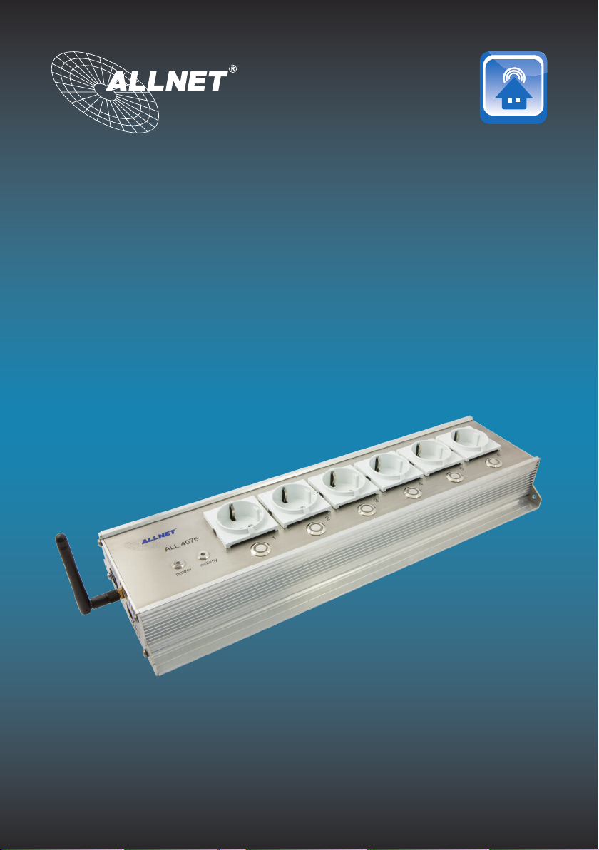
ALL4076
Page 2
ALL4076 WEB POWER STRIP
Important Note Page 03
Delivery / Safety / Installation Page Page 04
Connectors overview Page 05
Description Page 06
Customizing the ALL4076 to your network Page 07
LAN Setup Page 08
WLAN setup / Access Point settings Page 09
Wireless Client Page 11
DHCP Server Page 12
ALL4076 Conguration Page 13
Security Page 15
Environmental Control Page 16
Remote Control Page 17
Interface Page 18
Device Name / Language Page 20
Web servers and user Page 21
Date & Time Page 22
Device Status Page 23
Update Settings / Download User Manual Page 24
Functions / Plugwise service / Plugwise actuators Page 26
ALL3075 demon/ ALL3075 actuators Page 28
Timing Page 30
Integrated HomeAutomation XML commands Page 33
Reset / Cleaning / Specications Page 35
1.
8. Wichtige Hinweise
1.1
8.1 Verpackungsverordnung
„Grundsätzlich sind Hersteller wie auch Vertreiber verpichtet dafür zu sorgen, dass
Verkaufsverpackungen prinzipiell nach Gebrauch wieder vom Endverbraucher zurückgenommen
und einer erneuten Verwendung oder einer stofichen Verwertung zugeführt werden.“ (gemäß
§ 4 Satz 1 der VerpackVO). Sollten Sie als Kunde Probleme bei der Entsorgung der Verpackungsund Versandmaterialien haben, schreiben Sie bitte eine Email an info@allnet.de.
8.2. Recyclehinweis und RoHS Konformität
1.2
Bitte beachten Sie, dass Teile der Produkte der ALLNET® GmbH in
Recyclestellen abgegeben werden sollen bzw. nicht über den Hausmüll entsorgt
werden dürfen (Leiterplatten, Netzteil, etc.).
ALLNET® Produkte sind RoHs konform gefertigt (RoHS = engl. Restriction of the
use of certain hazardous substances; dt. „Beschränkung der Verwendung
bestimmter gefährlicher Stoffe“).
8.3. CE-Kennzeichnung
1.3
Die ALLNET® ALL4076 Websteckdosenleiste trägt die CE-Kennzeichnung.
Dieses Gerät erfüllt die Anforderungen der EU-Richtlinie: 89/336/EG Richtlinie über
elektromagnetische Verträglichkeit und die gegenseitige Anerkennung ihrer Konformität. Die Konformität mit der o.a. Richtlinie wird durch das CE-Zeichen auf dem
Gerät bestätigt.
9. Hersteller und Support
1.4
ALLNET® ist ein eingetragenes Warenzeichen der ALLNET® GmbH. Bei Fragen, Problemen und
für Produktinformationen sämtlicher Art wenden Sie sich bitte direkt an den Hersteller:
ALLNET® GmbH Computersysteme
Maistrasse 2
82110 Germering
E-Mail: support@allnet.de
Telefon: +49 (0)89 894 222 – 15
Fax: +49 (0)89 894 222 – 33
Internet: www.allnet.de
10. Garantie
1.5
Innerhalb der Garantiezeit beseitigen wir Fabrikations- und Materialfehler kostenlos.
Die für Ihr Land gültigen Garantiebestimmungen nden Sie auf der Homepage Ihres
Distributors. Bei Fragen oder Problemen zur Anwendung erreichen Sie uns während unserer
normalen Öffnungszeiten unter folgender Telefonnummer +49 (0)89 894 222 - 15 oder per
E-Mail: support@allnet.de.
Page 2 Page 3
Page 3
ALL4076WEBPowerStrip
Contents
Delivery
Please check the packaging and its content first:
> Is there something on the packaging that was damaged by shipping?
> Do you recognize if the case shows traces of use?
In case of damaged, do not let the device running. Please, if you have doubts do not hesitate to contact our
Technical Service.
Packaging content:
• ALLNET
• Power supply 230V
• Ethernet cable
• WLAN Antenna
• Manual of usage
• 19“ mounting brakets
Safety
Please note the following instructions:
Do not ever open the unit.
•
Never perform an installation during a lighting storm.
•
Make sure that the cables are well connected and sure footed.
•
Do not expose the unit to the direct sunlight.
•
Do not use this unit close to any heat sources.
•
Place the unit on surfaces that are heat sensitive.
•
Protect the device from moisture, dust, liquids and vapor.
•
Do not use the device in moist and potentially explosive environment.
•
Do not clean with solvent-based cleaning agents, but only a soft, dry anti-static cloth.
•
Repairs may only be performed by trained, authorized personnel.
•
In case of inappropriate usage, ALLNET® is out of responsibility.
•
Installation and mounting
General:
The ALL4076 WEB-Power Strip may only be used in dry environments. Make sure there is an adequate
ventilation. Avoid exposure to moisture, dust, sun or other heat radiation. The installation shall be made so that
the cables (network cable, power supply cable and other consumer cable) are not in tension. Make sure that the
maximum currents of 10A relay outputs are not exceeded.
®
ALL4076 WEB-Power Strip
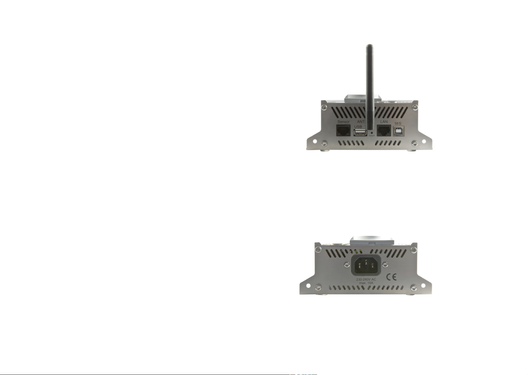
Connectors overview
Sensor: Temperature & Humidity Sensor (Optional)
USB: USB Host port for Plugwise Dongle
Ant: WLAN Antenna
LAN: Ethernet LAN Connector
M/S: USB On / Off Detector
Power: 230-240V AC - Connection max. 10A
Page 4 Page 5
Page 4
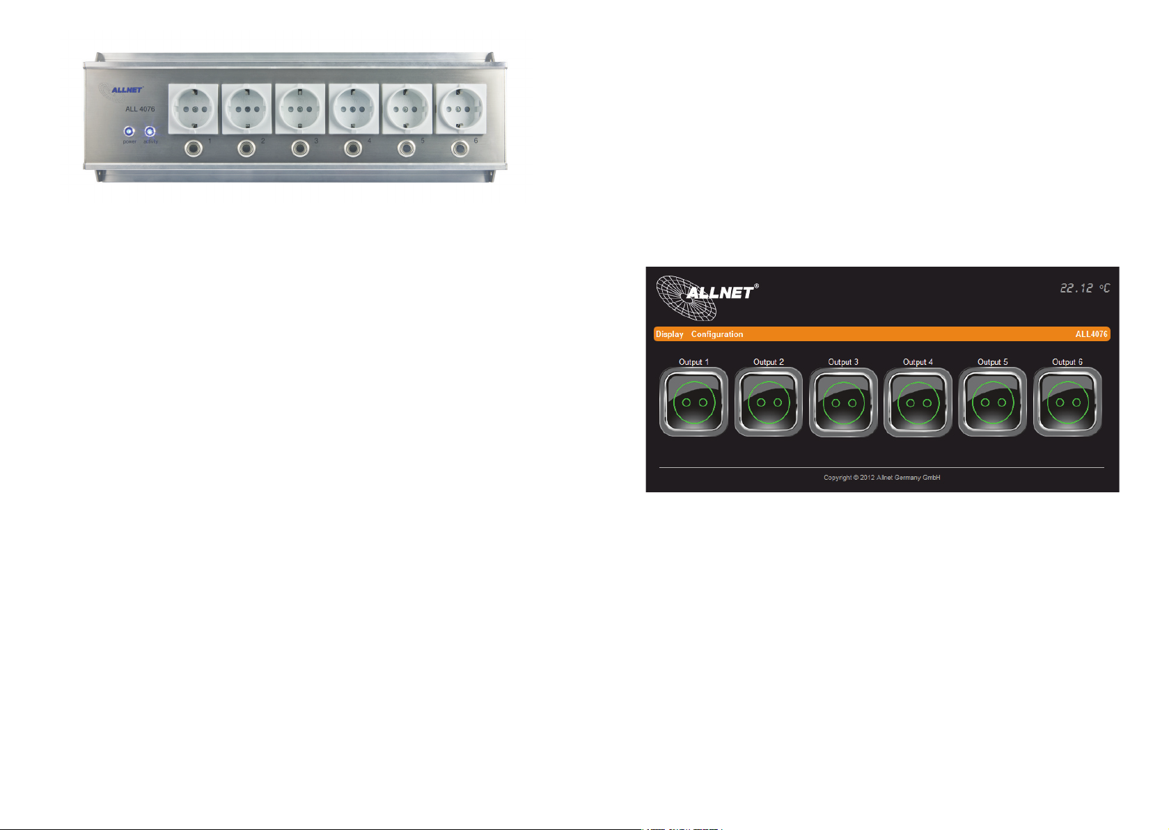
Power: Power ON displayed
Activity: Flashing when unit is started.
Manuel button: Button for manual switching of socket.
Schuko plugs: 6x push sockets max. 10A
Description
The heart of the ALL4076 is based on an embedded Linux. The CPU module is a MIPS with 400MHz core, 64MB
RAM and 32MB flash as memory. The boot process takes about 90 seconds; in this interval any activity is
performed. After the boot process ends, the Activity LED will start to flash. Thereafter, the ALL4076 can be
controlled/switched both via manual switch and via web interface.
The control of the individual output can be done by different actions.
1. Pressing the button, permanent switching or pulsing it.
2. Pressing the button on the web interface.
3. Create a schedule to control it. (Once, several times, on weekdays).
4. Recognize a switched on over an equipment connected via USB-B connector.
5. Temperature values (Optional Sensor required).
6. Humidity values (Optional Sensor required).
A part of its own, built-in sockets, the ALL4076 can be expanded with all ALL307x series. Plugwise could also be
connected. The following functions can be performed by the ALL4076 power strip:
WEB interface control, timer control and display of consumption parameters.
Customizing the ALL4076 to your network
Initial connection using LAN cable
1. Connect your ALL4076 to your Ethernet switch using the attached LAN cable. Make sure that the
connector is well connected.
2. Connection between ALL4076 and your PC / MAC: the ALL4076 communicates using the TCP/IPprotocol with the connected device. Thus the ALL4076 is recognized by your PC / MAC, if they are in the
same network segment. By default, the ALL4076 WEB power strip has:
IP address: 192.168.0.100
Subnet Mask: 255.255.255.0
3. Please, give to your PC or MAC a free address between 192.168.0.1 - 192.168.0.254 (not
192.168.0.100 – this is the one used from your ALL4076 WEB – Power strip).
4. Open a web browser (Internet Explorer, Firefox...) and type the address 192.168.0.100, it will appear the
ALL4076 WEB-Power strip homepage.
Page 6 Page 7
Page 5
LAN Setup
Setting the IP address and network access parameters
In your Web browser, enter please the address of the ALL4076 Web Power strip.
Option under „Configuration“ > „LAN setting“
WLAN Setup
Configure the WLAN Parameters
In your Web browser, enter the web address of the ALL4076 Web Power strip.
Settings under "Configuration"> "WLAN settings".
WLAN Mode Selection
Select the operating mode for WLAN. There are 3 options available.
- Power off. WLAN is disabled. (Default setting)
- Access Point. The ALL4076 itself works as a wireless access point. All devices that are in your local area
network and the ALL4076 are thus accessible via WLAN.
- Wireless client. The ALL4076 can be connected to an existing WLAN.
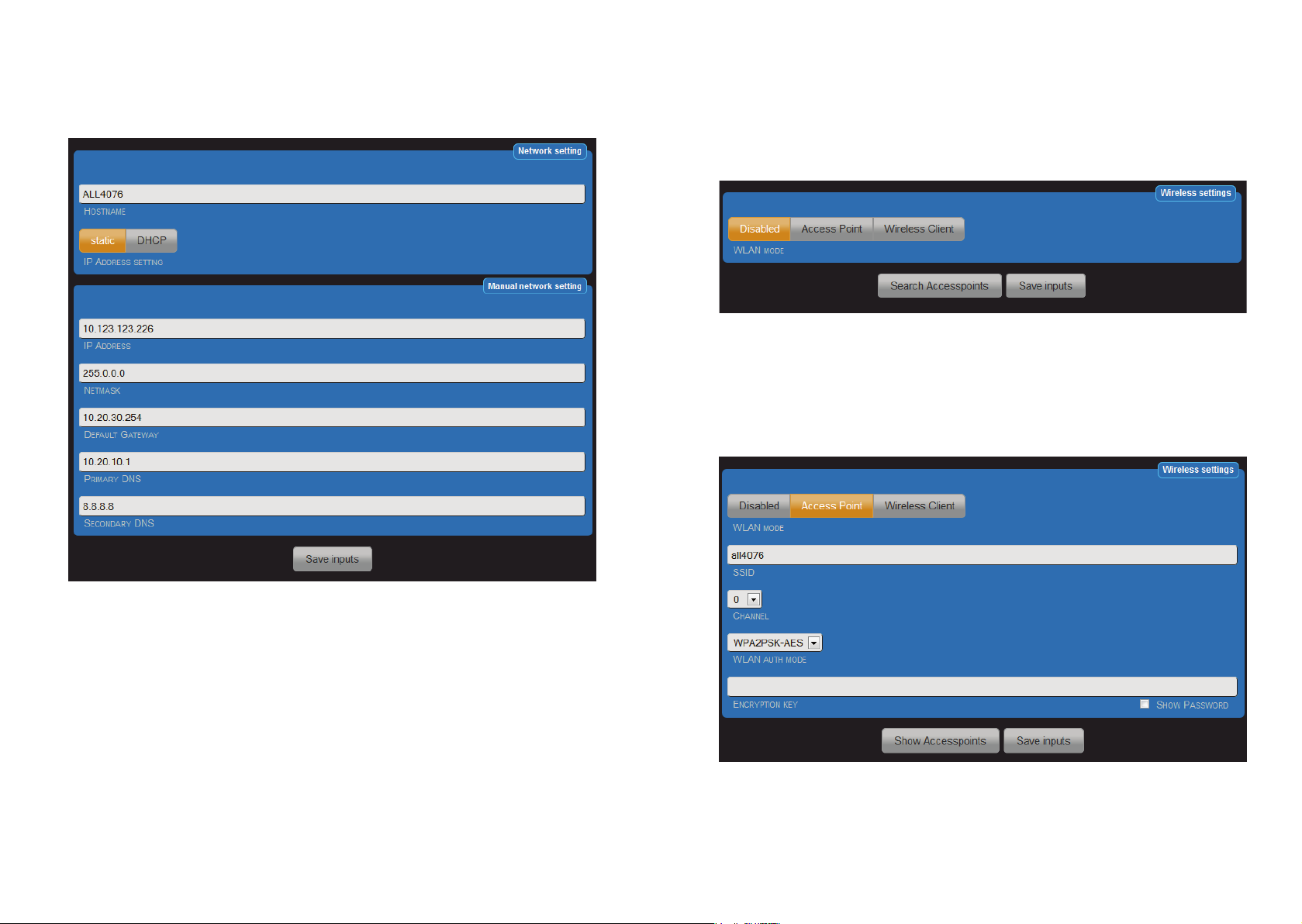
Access Point Settings
a. HOSTNAME: Enter a name for your ALL4076, this will be reported/used in your network. Valid only the
following characters: a-z, A-Z, 1-9 and the hyphen (not to be used at the beginning or at the end). It
cannot contain special characters and space. Maximum 15 characters can be used.
b. IP ADDRESS SETTING: When you select "DHCP", the ALL4076 uses the DHCP server to assign itself
an IP, Points c) – g) to omit. In "static" (default), the address is assigned manually.
c. IP ADDRESS: Address of the ALL4076 in the network (please, make sure you do not assign an IP
address twice – Ask your network administrator).
d. NETMASK: Default setting 255.255.255.0
e. DEFAULT GATEWAY: Please fill in the default gateway, usually the IP address of your router.
f. PRIMARY DNS: Here, you enter the address of your DNS server. In home networks usually the IP
address of your router.
g. SECONDARY DNS: Default setting 8.8.8.8. Please modify it only when you are sure that exists a
secondary DNS in your network.
After changing parameters press "Save settings". The ALL4076 automatically restarts. After about 90
seconds, the ALL4076 with the new parameters will be accessible.
When operating as an access point, you can press the button "Show Access Points" to use the information shown
and clearly differentiate from the existing WLANs.
Now set your login details for your home wireless network. If you use this mode and you are connected to a LAN,
the ALL4076 acts as a wireless access point. This mode can also be used alone to control the ALL4076 without
Page 8 Page 9
Page 6
LAN connection. E.G. from your phone via Wi-Fi. For this mode, has sense to activate the DHCP server. The
description is given in a later chapter.
a) SSID: Please enter the name of your network
b) Channel: Select a free channel from the drop-down menu. The busy channels you can see from the
display of the function "Show Access Points"
c) WLAN auth mode: Select the same of your wireless encryption method.
(OPEN NONE, shared WEB, WPA-PSK-TKIP, WPA-PSK AES, TKIP WPA2PSK, WPA2PSKAES(default)).
d) Encryption
After entering the parameters press "Save settings". The ALL4076 automatically restarts. After about 90sec
should the ALL4076, with the new parameters, be accessible via WLAN.
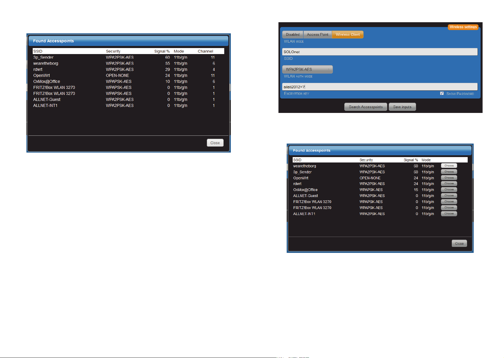
Wireless Client
When operating as a wireless client, you can by clicking the "Search Access Point", search in the area for
available wireless access points and display them. Simply press the button "Select" in the appropriate line, to
connect with wireless network. All data except of the encryption key will be taken.
The automatic transfer of parameters SSID, CHANNEL, WLAN AUTH MODE is done by pressing the "Select"
button. The "encryption key" must always be entered manually and must be identical to the one of the selected
WLAN.
Alternatively, you can also manually set your access data of your home wireless network.
a) SSID: Entry must be the same with your WLAN.
b) CHANNEL: Entry must be the same with your WLAN.
c) WLAN AUTH MODE: Select the same of your wireless encryption method.
(OPEN NONE, shared WEB, WPA-PSK-TKIP, WPA-PSK AES, TKIP WPA2PSK, WPA2PSKAES (default)).
d) ENCRYPTION: Entry must be the same with your WLAN.
With "SHOW PASSWORD" you can visually check, that any typing error occurred.
Page 10 Page 11
Page 7

After entering the parameters press "Save settings". The ALL4076 automatically restarts.
After about 90sec should the ALL4076, with the new parameters, be accessible via WLAN.
DHCP Server
Settings under "Configuration" -> "DHCP server".
The ALL4076 can act as a DHCP server. Enable this feature if the ALL4076 run as a standalone access point.
Note: if this feature is enabled and the ALL4076 connected erroneously with your LAN, it interferes. Select for
standalone operation an IP address that is different from your existing LAN and WLAN in the setting used. E.g. an
address in the range 192.168.100.xxx
See also: http://en.wikipedia.org/wiki/Private_network
a) DHCP Server Operation Mode: Disabled / Enabled (Default = Disabled).
b) IP Address Range starts from:
default = 192.168.0.110.
c) IP Address Range ends with: The automatic assignment of IP addresses finishes with xxx.xxx.xxx.xxx
default =192.168.0.149 .
d) Netmask: Default = 255.255.255.0 . Fit to 192.168.xxx.xxx .
e) Gateway:
in stand-alone mode it does not matter. Otherwise your router address.
The automatic assignment of IP addresses starts with xxx.xxx.xxx.xxx
f) DNS 1: Your DNS server address. With home networks the router address. For stand-alone operations it
does not matter.
g) DNS 2: In stand-alone mode it does not matter.
h) DNS 3: In stand-alone mode it does not matter.
ALL4076 Configuration
In your Web browser, enter the address of the ALL4076 WEB socket.
Settings under "Configuration" -> "Device Settings"
Here you can configure the settings for each output. Note that each output can be switched individually.
1. Output: Enabled / Disabled
2. Lock Pushbutton: Enabled / Disabled. The ON / OFF button on the power strip can be blocked and not
usable
3. Switching type: switch / impulse
a) when the switch mode is selected, it acts like a normal switch.
b) when the impulse mode is selected, it will stay for a limited period On or Off. If you select this mode,
an additional line will appear to select the time in seconds.
4. Permanent state of output: On / Off / Last state. Important in case of power failure. (Default = off)
5. USB Master / Slave: Enabled / Disabled. It detects a device which is connected to the USB-B connector.
If this device is active, the selected output may also be active.
6. Name: Choose a suitable name for the task. The name will be displayed on the web page.
7. Description: The description is the detailed information and is not displayed on the main page.
8. Choose an icon: you can select it from existing icons.
Example: Screenshot by setting Impulse
Page 12 Page 13
Page 8

In the example, this output for the impulse is set to 200sec.
Security
Here you can configure the settings for the operating time of the manual switch.
After changing parameters press "Save settings".
Page 14 Page 15
Page 9

Environmental Control
Environmental Control
By Enviromental Control, you can evaluate the signals of a sensor for temperature and humidity to check their
output.
This tab is available only when a sensor is located on the ALL4076 socket.
Note: The control of output related to temperature and/or humidity can be done following different possibility: The
icon on the main page, the button on the ALL4076 WEB power strip and through a timer. Re-activation of an
output occurs only when a threshold has been exceeded again.
The temperature and humidity control values affect the output edge-triggered. All other possible switches are
level-triggered.
Switching trigger: OFF ( Default)
Switching trigger: Temperature
Switching temperature range: The active region could be selected by moving the two ends. The blue area is the
normal condition. The areas located outside of the switching state, will not be taken in consideration after reboot:
"state of the output after reboot".
Examples:
In this screenshot the operating range is from 23 to 26 °C, e.g. for switching ON a heater.
Swicthing trigger: humidity
Humidity range: the active region could be selected by moving the two ends as done for the temperature before.
Switching trigger: Both
The evaluation of temperature and humidity will be carried out.
By Enviromental Control, you can evaluate the signals of a sensor for temperature and humidity to check their
output.
This tab is available only when a sensor is located on the ALL4076 socket.
Note: The control of output related to temperature and/or humidity can be done following different possibility: The
icon on the main page, the button on the ALL4076 WEB power strip and through a timer. Re-activation of an
output occurs only when a threshold has been exceeded again.
The temperature and humidity control values affect the output edge-triggered. All other possible switches are
level-triggered.
Switching trigger: OFF ( Default)
All sensors can be used: ALL3006 (Temperature) and ALL3018 (Temperature and Humidity).
The current values are displayed on the main page, when the sensors are connected. In case of communication
lost, then an error message will appear.
Example:
Remote Control
In the tab „Remote Control“, you can set the access to your ALL4076 using username and password. This
password will be also required in the XML queries.
Switching trigger: Temperature
Switching temperature range: The active region could be selected by moving the two ends. The blue area is the
normal condition. The areas located outside of the switching state, will not be taken in consideration after reboot:
"state of the output after reboot".
Examples:
In this screenshot the operating range is from 23 to 26 °C, e.g. for switching ON a heater.
Swicthing trigger: humidity
Humidity range: the active region could be selected by moving the two ends as done for the temperature before.
Switching trigger: Both
The evaluation of temperature and humidity will be carried out.
1. Username:
2. Password:
After changing parameters, please press "Save settings".
Page 16 Page 17
Page 10

Interface
Configuration of the interface
Option under „Configuration“ > „Interface“
All settings here will affect the display of the main page.
1. Set display width manual or automatic: Automatic means that the possible number of icons is limited by
the display width in pixels (2.a). Manually defines the maximum number of icons in a row (2b). Default =
Automatic
2. a. Minimal Display Width: Specifies the width of the display on the main page. Default = 800
b. Maximum number of actuators in a row: Specifies the maximum number of icons. Default = 4
3. Show title and Menu bar: Enabled / Disabled. This allows the display of the menu bar on the main page
to be suppressed. Default = Enabled.
4. Type of Control buttons: Icon / On/Off. The choice between icon and simplified circuit symbols.
5. Color for state “ON”. Only adjustable when ICONS has been choose as Type of the button
6. Color for state “OFF”. Only adjustable when ICONS has been choose as Type of the button.
7. Shows actor names: Enabled / Disabled. On the main page so that the display can be limited to symbols.
Note: When the main bar menu is disabled, please use this symbol to get back to it.
Example of the configuration of the mainpage:
Display of the main page with default parameters and attached temperature and humidity sensors.
Here, display of the main page with a disabled menu bar.
Switching to possible setting by clicking on
Here, display of the main page with a disabled menu bar and disabled actor names.
Page 18 Page 19
Page 11

Device Name
Device Name
Settings under „Configuration“ > „Device name“
This device name is used in the menu bar.
Menu line:
Language Options
Settings under "Configuration"> "Change Language"
You can choose between English, German or Italian languages.
Settings under „Configuration“ > „Device name“
This device name is used in the menu bar.
Web Server and User
Settings under „Configuration“ > „Web Server and Userr“
It is possible to access the website with a secure transfer (https). Additionally, a user and admin profile can be set
up. Thereby it is possible to create a limit group of users. In addition, the access of normal users can be
prevented working on the settings.
Menu line:
Language Options
Settings under "Configuration"> "Change Language"
You can choose between English, German or Italian languages.
1. Operation mode with / without SSL: Default = without
2. http Port Number : http = 80 / https = 443
3. Username:
4. Password:
5. Admin Username:
6. Admin Password:
Note: It´s recommended to give always an entry for Admin Username and Admin Password, in addition of
Username and password. The usage of the same set up for username and password does not make any sense,
cause otherwise through the open access, all website will result unprotected.
Page 20 Page 21
Page 12
Date & Time
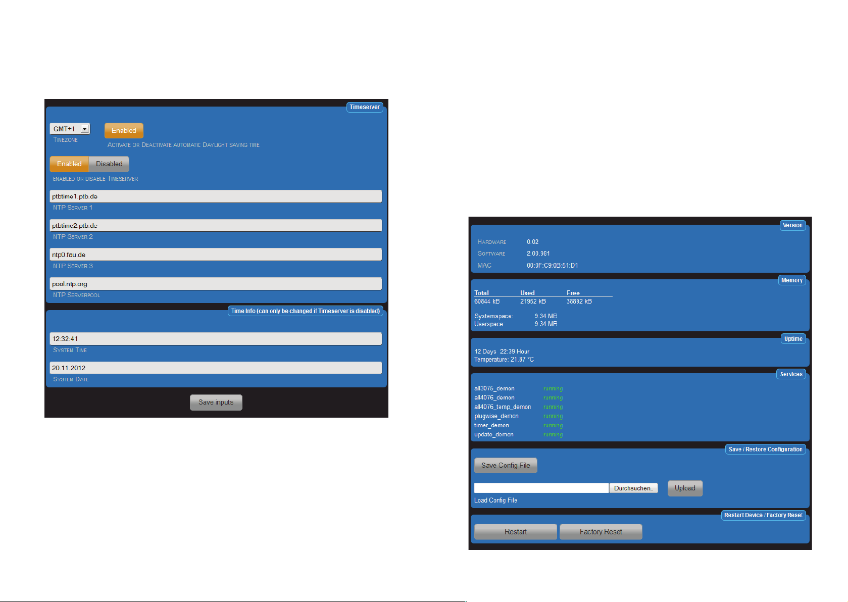
Date & Time
Settings under "Configuration"> "Date & Time"
The ALL4076 synchronizes its system time with an NTP server. The time query to the NTP happens during the
boot process and all 24H. Monitoring is made by the port 123. This port must be let open on the firewall.
Settings under "Configuration"> "Date & Time"
The ALL4076 synchronizes its system time with an NTP server. The time query to the NTP happens during the
boot process and all 24H. Monitoring is made by the port 123. This port must be let open on the firewall.
Device Status
Options under „Configuration“ > „Device Status“
The website shows an overview about the system:
• Hardware Version
• Software Version
• MAC Address
• Memory usage
• Operating time
• External temperature and humidity occurs only when the sensors are connected.
• Services overview
The following settings and features include:
• Set the maximum log file size
• Logs view
• Save the current configuration
• Restore a saved configuration
• Factory Reset
• Restarting
Page 22 Page 23
Page 13

Update settings
Option under „Configuration“ > „Update settings“
It is possible to manually check for updates and install them immediately. By using the factory settings, the
ALL4076 will search for update at each boot and once every 24H. There is even the option to download a
firmware file directly.
Download user manual
Option under „Configuration“ > „Download user manual”
Independently on the previous language in the interface, the manual download will start in the appropriate
language.
Page 24 Page 25
Page 14

Functions
“Functions” offers you the opportunity to use in addition to the internal switching functions other external actors.
With the ALL4076 you can control the ALL3073, ALL3075, ALL3075V2 and Plugwise actuators. To use those
actuators appropriate, it is necessary to enable the various services. In addition, a time control can be set up.
Plugwise Service
Settings under „Functions“ > „Plugwise Service“
You need a complete Plugwise kit consisting of Plugwise Stick and Plugwise Circle and Circle +. Plugwise Circle
are pure actuators and they can only turn on or off a load. Plugwise Circle + are actuators with an additional
opportunity to display the current consumption. The communication between Plugwise stick and Plugwise Circle
is performed by the Zigbee wireless protocol. By activating the Plugwise service, Plugwise stick will connect to the
ALL4076. If the Plugwise stick will be removed, then also the Plugwise service can be disabled, otherwise the
system will permanently diplay error messages.
1. Plugwise UDP Port: Default = 54002 fixed parameters
2. Plugwise Serial Port: Default = /dev/ttyUSB0
3. Shows Watts in the panel: Default = enabled
Plugwise Actors
Settings under „Functions“ > „Plugwise Actors“
Settings Plugwise actuators
1. Plugwise Actor: Enabled / Disabled
2. Actor name: Choose a suitable name fort he task. This name is displayed in the main page.
3. Actor description: the description contains the detailed information. It will not be displayed in the main
page.
4. Plugwise MAC Address: you will find it on the connector side of the Plugwise Circle actor. E.g.
000D60000768FC9. Please enter the full 16-digit number.
5. Choose an ICON: Choose a suitable icon.
After clicking on the plus sign, a mask for the establishment of a new actuator will be automatically open.
Page 26 Page 27
Page 15
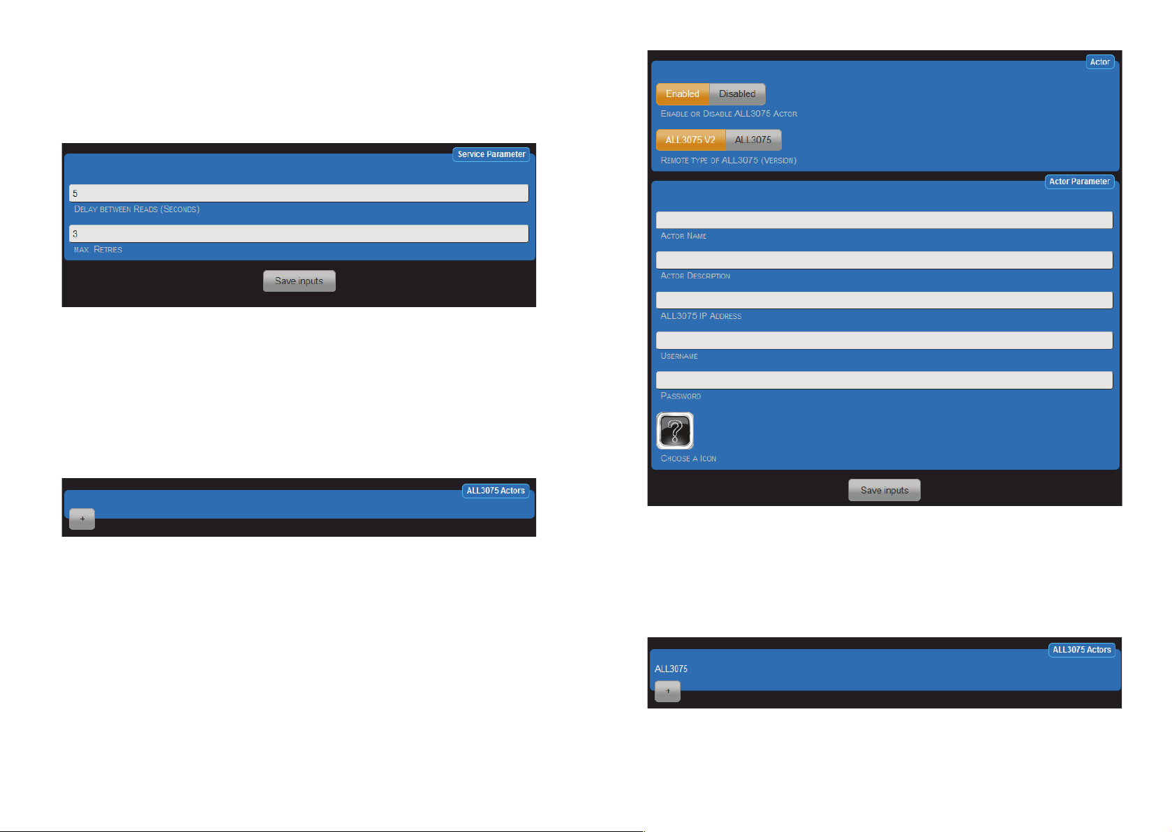
ALL3075 Demon
Settings under „Functions“ > „ALL3075 Demon“
The ALL4076 can be extended by using the ALL3075 and ALL3075V2 actuators. The ALL3075 is an actuator and
can evaluate the power consumption. The ALL3075V2 can also estimate the power consumption and even more
the communication can run over LAN or WLAN.
1. Delay between reads (seconds): Default = 5 Sec. In this settings, the current state of the ALL3075 will be
queried every 5 seconds. The transmission rate of the actuator is not affected by this settings.
2. Max. retries: Default = 3. Displaying an error message after 3 failed connection attempts. It will continue
to try to reach the actuator every 5 sec.
ALL3075 Actors
Settings under „Functions“ > ALL3075 Actors“
After clicking the plus sign, the mask to set up the ALL3075 actuator automatically will open
1. ALL3075 Actor Enabled or Disabled.
2. Remote Type of the ALL3075 (Version): select the appropriate type.
3. Actor Name: Choose a suitable name for the task. This name will be displayed in the web page.
4. Actor Description: contains the detailed information. It will not be displayed in the main page.
5. ALL3075 IP Address: Each ALL3075 has its own IP address. Please enter here the address.
6. Username: Only if you have set in the ALL3075 a username, please enter it here.
7. Password: Only if you have set in the ALL3075 a password, please enter it here.
8. Choose a ICON: Choose a suitable icon.
Page 28 Page 29
Page 16

Timing
Settings under "Functions" > "Timing Control"
Time-dependent switching points can be created. The resolution is 1 second. A maximum of 128 control points
are defined.
After clicking on the plus sign in the mask is automatically opened a window to insert new set points.
1. Timer: Enabled / Disabled.
2. Timer Name: Choose a suitable name for the timers. This name will appear in the over view page.
3. Timer Description: the description provides detailed information which are not in the overview.
Page 30 Page 31
Page 17

4. Start time: Use the three sliders to select the desired time
Integrated HomeAutomation XML commands
The ALL4076 can show the current status using XML commands. Even the actuators can be controlled via XML.
The call to http://192.168.0.100/xml shows the first page with help text.
Microsoft Explorer can not display correctly the XML representation. Please use e.g. Firefox.
5. Action: On / Off. When "On" is selected, at this moment the relay is closed. For different tasks, it may be
necessary that the relay is open at the starting point, "off" then can be selected.
6. Choose actor or program: Only actuators supported.
7. Active on weekdays: Select the desired days of the week.
8. Choose stop time:
9. Action: On / Off. When "Off" is selected, at that moment the relay is opened. For different tasks, it may
be necessary that the relay is closed at the stop point, then can be turned "On".
10. Choose actuator or program: Only actuators supported.
11. Active on weekdays: Select the desired days of the week .
After saving all the timers, they will be listed in the table.
Commands example:
http://192.168.0.100/xml/?q=0 shows the status of all the actuators.
http://192.168.0.100/xml/?q=1&actor=1&switch=1 switches an actuator.
http://192.168.0.100 /xml/?q=2&actor=1 shows the status of a single actuator.
http://192.168.0.100 /xml/?q=3 shows the status of the ALL4076.
Example. Display of a single actuator.
Page 32 Page 33
Page 18

<actor_id>1 Actuator ID
<actor_name>Output 1 Actuator name
<actor_state>1 Signal status 0 = OFF, 1 = ON, 2 = ERROR
<actor_watt>0 Display Watt.*
<actor_volt>0 Dislpay Voltage.*
<actor_ampere>0 Display Current.*
<actor_frequency>0 Display Frequency.*
<actor_setstate>3 Confirmation of submitted values when switching the actuator 0 = OFF, 1 =
ON, 3 = Nothing to do (e.g. Actuator is ON and is going to be turned ON)
*only with actuators like Plugwise Circle+ and ALL3075V2
Reset
It may happen that your ALL4076 by faulty user settings is not accessible, or that a password has been set and
forgot, etc. In this case you can use the following reset procedure, to reset all settings to factory default (reset the
device back to factory default settings means that your values will be lost): remove the power supply from your
device. Using a non-conducting pointed object (eg. a toothpick) press the RESET button through the small hole
next to the USB port and keep it pressed (PUSH and STAY on the button!). Give again power to your ALL4076
and wait about 3 minutes until the BUS LED starts to flash. ONLY NOW the reset button can be released. After
that is the reset process completed and all the settings are reset to its factory state.
Cleaning
Before cleaning, unplug the unit from the home socket. Use a soft cloth (better if microfiber cloth). Never use
detergent, alcohol or other solvents. Please note that within the housing there is modern electronic components.
Therefore, never use so much water or detergent, that by the side vents (holes) or through the small gaps
between the metal frame or through the recesses of the connections can penetrate into the interior of the
ALL4076. If it should happen, pack the device to send it back and please contact our support.
Specifications
• Operating voltage: 230V AC max. 10A
• Relays switching current: max. 10 Ampere
• Network: 10BaseT 100BaseTX
• Network connection: RJ45
• Ambient operating temperature: 5 - 40°C
• Humidity: 10% - 85% (non-condensing)
• Storage temperature: -20 - 60°C
• Storage humidity: 5% - 90% (non-condensing)
• Housing: Aluminium housing
• Protocols: HTTP/HTTPS TCP/IP
• Wireless LAN: 2,4 GHz Wireless N, up to 150 Mbps
• Supported Standards: IEEE 802.3 IEEE 802.3u IEEE 802.11b/g/n
• Operating Systems: all network-compatible operating systems
• Dimensions (L*W*H): 425 x 140 x 55 mm (Lenght x Width x Height)
• Weight: 2500g (without cable and accessories)
• Manufacturer: ALLNET
®
GmbH
Page 34 Page 35
Page 19

Page 36
 Loading...