

Page 1
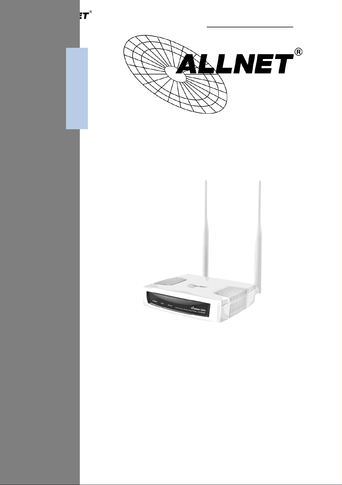
ALL02850N User’s Manual
ALL02850N
WLAN N Access Point /Client
Bridge
0
Page 2

ALL02850N User’s Manual
Table of Contents
1 INTRODUCTION 5
1.1 Features and Benefits 5
1.2 Package Contents 6
1.3 System Requirements 6
1.4 Applications 6
2 BEFORE YOU BEGIN 8
2.1 Considerations for Wireless Installation 8
2.2 Computer Settings (Windows XP/Windows Vista/Windows 7) 9
2.3 Apple Mac X OS 11
2.4 Hardware Installation 12
3 CONFIGURING YOUR CLIENT BRIDGE 14
3.1 Default Settings 14
3.2 Web Configuration 15
4 BUILDING A WIRELESS NETWORK 17
4.1 Client Bridge Mode 17
4.2 Access Point Mode 18
4.3 WDS AP Mode 19
4.4 WDS Bridge Mode 20
4.5 Router Mode 21
4.6 Repeater Mode 22
5 SYSTEM 23
5.1 Operation Mode 23
5.2 Status 24
5.3 DHCP 27
5.4 Schedule 29
1
Page 3

ALL02850N User’s Manual
5.5 Event Log 31
5.6 Monitor 32
6 WIRELESS 33
6.1 Status 33
6.2 Basic 35
6.3 Site Survey 39
6.4 Advanced 42
6.5 Security 45
6.6 Filter 49
6.7 WPS (Wi-Fi Protected Setup) 50
6.8 Client List 52
6.9 VLAN 53
6.10 AP Profile 54
7 NETWORK 56
7.1 Status 56
7.2 LAN 57
7.3 Spanning Tree 59
7.4 WAN (Router mode) 60
7.4.1 Static IP Address 60
7.4.2 Dynamic IP Address 61
7.4.3 PPP over Ethernet (PPPoE) 62
7.4.4 Point-to-Point Tunneling Protocol (PPTP) 62
8 FIREWALL 64
8.1 Enable 64
8.2 DMZ 65
8.3 DoS 66
8.4 MAC Filter 67
8.5 IP Filter 68
8.6 URL Filter 69
2
Page 4

ALL02850N User’s Manual
9 ADVANCED 70
9.1 Network Address Translation (NAT) 70
9.2 Port Mapping 71
9.3 Port Forwarding 72
9.4 Port Triggering 73
9.5 Application Layer Gateway (ALG) 74
9.6 Universal Plug and Play (UPnP) 75
9.7 Quality of Service (QoS) 76
9.8 Static Routing 78
9.9 Dynamic Routing 79
9.10 Routing Table 80
10 MANAGEMENT 81
10.1 Admin 81
10.2 SNMP 82
10.3 Firmware Upgrade 84
10.4 Configure 86
10.5 Reset 87
11 TOOLS 88
11.1 Time Setting 88
11.2 Diagnosis 89
12 LOGOUT 90
APPENDIX A – FCC INTERFERENCE STATEMENT 91
APPENDIX B – IC INTERFERENCE STATEMENT 92
APPENDIX C – CE INTERFERENCE STATEMENT 0
3
Page 5

ALL02850N User’s Manual
4
Page 6

ALL02850N User’s Manual
1 Introduction
The ALL02850N is a multi-function 802.11b/g/n product with 6 major
multi-functions. The ALL02850N is designed to operate in every working environment
including enterprises.
The ALL02850N is a Wireless Network device that delivers up to 6x faster speeds and
7x extended coverage than 802.11b/g devices. The ALL02850N supports use in the
home network with superior throughput, performance, and significant wireless range.
To protect data during wireless transmissions, the ALL02850N encrypts all wireless
transmissions through WEP data encryption and supports WPA/WPA2 encryption.
The ALL02850N has MAC address filtering to allow users to select differing stations to
access the network. The ALL02850N is an ideal product to ensure network safety for
both home and enterprise environments.
1.1 Features and Benefits
Features Benefits
High Speed Data Rate Up to 300
Mbps
10/100 Fast Ethernet Support up to 100Mbps networking speed.
IEEE 802.11n Draft Compliant and
Backwards Compatible with
802.11b/g devices
Multi-Function Allowing users to select Access Point, Client
Point-to-Point or
Point-to-Multipoint Wireless
Connectivity
Capable of handling heavy data payloads such as
HD multimedia streaming.
Fully compatible with IEEE 802.11b/g/n devices.
Bridge, WDS AP, WDS Bridge, Router or Universal
Repeater mode in various applications.
Allows transfer of data from building to building.
Support Multiple SSID in AP
mode (up to 4)
WPA/WPA2/IEEE 802.1x Support Powerful data security.
MAC Address Filtering in AP
Mode
User Isolation Support (AP mode) Protect the private network between client users.
Allow clients to access different networks through
a single access point and assign different policies
and functions for each SSID through the built in
software.
Ensure a secure network connection.
5
Page 7

ALL02850N User’s Manual
Power-over-Ethernet (IEEE802.3af) Flexible Access Point locations.
Save User Settings Firmware upgrade does not delete user settings.
SNMP Remote Configuration
Management
QoS (WMM) support Enhanced user performance and density.
Allows remote connection to configure or manage
the ALL02850N easily.
1.2 Package Contents
The ALL02850N package contains the following items (all items must be in package to
issue a refund):
ALL02850N Wireless Long Range Multi-Function Client Bridge
/ Access Point
12V/1A 100V~240V Power Adapter
RJ-45 Ethernet Cable
Detachable Antenna
CD with User’s Manual
Quick Installation Guide
Please use only the power supply unit that is delivered with the device.
Bitte verwenden Sie nur das mitgelieferte Netzteil.
1.3 System Requirements
The following are the minimum system requirements in order configure the device.
Computer with an Ethernet interface or Wireless Network.
Windows, Mac OS, or Linux based operating systems.
Web-Browsing Application (example: Internet Explorer, FireFox,
Safari, or other similar software)
1.4 Applications
Wireless LAN products are easy to install and highly efficient. The following list
describes some of the many applications made possible through the power and
flexibility of wireless LANs:
a) Difficult-to-Wire Environments
There are many situations where wires cannot be laid easily or cannot be hidden
from view. Older buildings, sites with multiple buildings, and/or areas make the
6
Page 8

ALL02850N User’s Manual
installation of a Wired LAN impossible, impractical, and/or expensive.
b) Temporary Workgroups
Create temporary workgroups/networks in open areas such as parks, athletic
arenas, exhibition centers, temporary offices, and construction sites where one
wants a temporary Wireless LAN established and easily removed.
c) The Ability to Access Real-Time Information
Doctors/Nurses, Point-of-Sale Employees, and/or Warehouse Workers can
access real-time information while dealing with patients, serving customers,
and/or processing information.
d) Frequently Changing Environments
Set up networks in environments that change frequently (i.e.: Show Rooms,
Exhibits, etc.).
e) Small Office and Home Office (SOHO) Networks
SOHO users need a cost-effective, easy and quick installation of a small network.
f) Wireless Extensions to Ethernet Networks
Extend network coverage where the network cannot reach (i.e.: There is no
wired internet connection to reach certain location of the environment).
g) Wired LAN Backup
Implement wireless LANs to provide backup for mission-critical applications
running on wired networks.
h) Training/Educational Facilities
Training sites at corporations and students at universities use wireless
connectivity to ease access to information, information exchanges, and learning.
7
Page 9

ALL02850N User’s Manual
2 Before you Begin
This section will guide you through the installation process. Placement of the
ENGENIUS ALL02850N is essential to maximize the ALL02850N’s performance. Avoid
placing the ALL02850N in an enclosed space such as a closet, cabinet, or wardrobe.
2.1 Considerations for Wireless Installation
The operating distance of all wireless devices cannot be pre-determined due to a
number of unknown obstacles in the environment that the device is deployed in.
These could be the number, thickness, and location of walls, ceilings, or other objects
that the ALL02850N’s wireless signals must pass through. Here are some key
guidelines to allow the ALL02850N to have optimal wireless range.
Keep the number of walls and/or ceilings between the
ALL02850N and other network devices to a minimum. Each
wall and/or ceiling can reduce the signal strength, resulting in
lower signal strength.
Building materials makes a difference. A solid metal door
and/or aluminum stubs may have a significant negative effect
on the signal strength of the ALL02850N. Locate your wireless
devices carefully so the signal can pass through a drywall
and/or open doorways. Materials such as glass, steel, metal,
concrete, water (example: fish tanks), mirrors, file cabinets,
and/or brick can also lower your wireless signal strength.
Interferences can also come from other electrical devices
and/or appliances that generate RF noise. The most usual
types are microwaves and cordless phones.
8
Page 10
ALL02850N User’s Manual
2.2 Computer Settings (Windows XP/Windows
Vista/Windows 7)
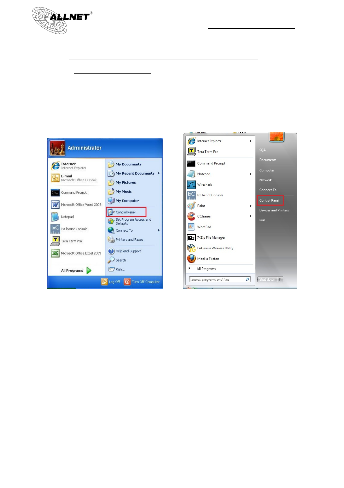
In order to use the ALL02850N, you must first configure the TCP/IPv4 connection of
your computer system.
Click Start button and select Control Panel.
Windows XP Windows Vista/Windows 7
9
Page 11
ALL02850N User’s Manual
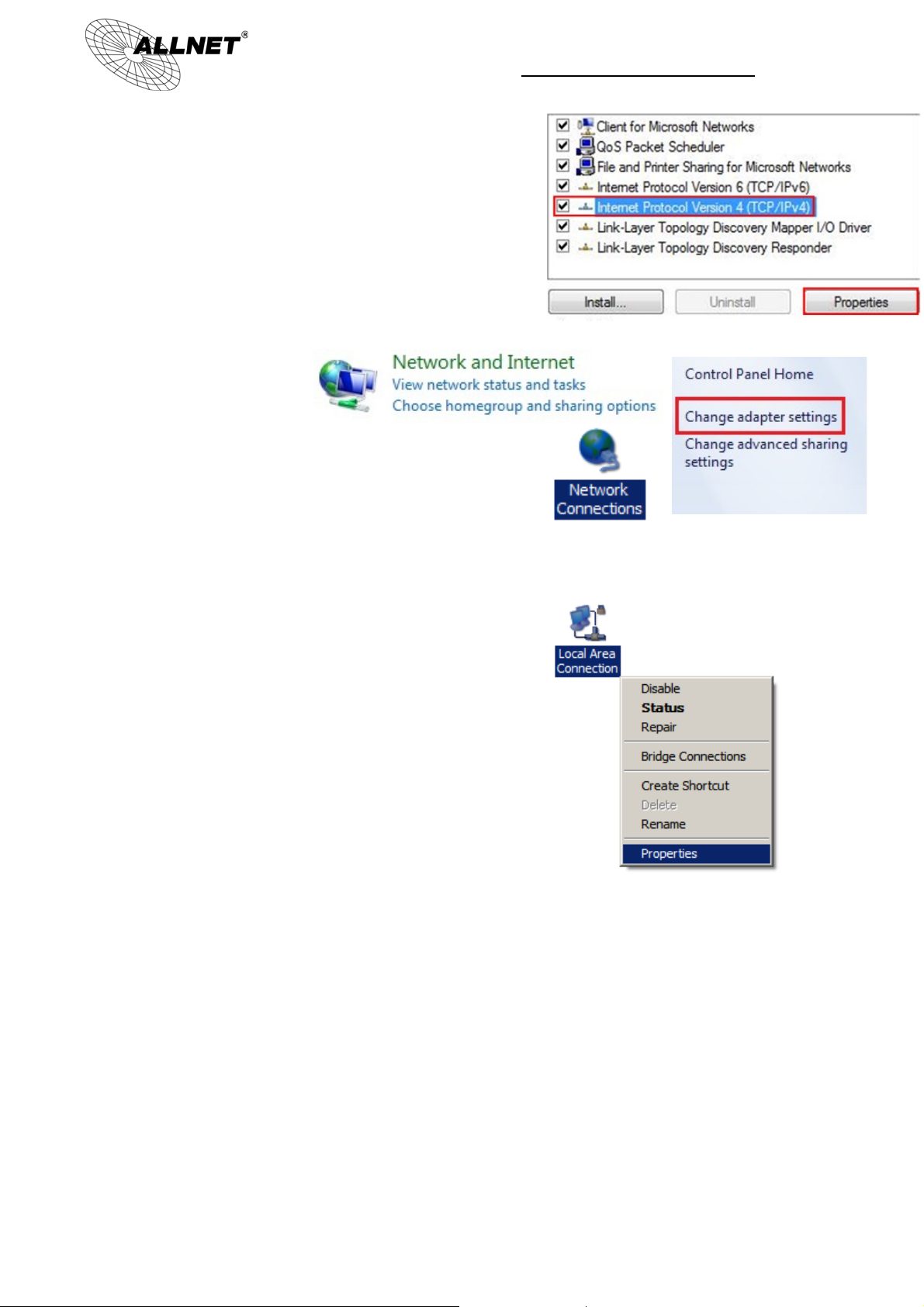
In Windows XP, click Network Connections
In Windows 7, click View Network Status
and Tasks in the Network and Internet
section, then select
Change Adapter
Settings
Right click on Local Area Connection and
select Properties
Highlight Internet Protocol Version 4 (TCP/IPv4) and select Properties
10
Page 12
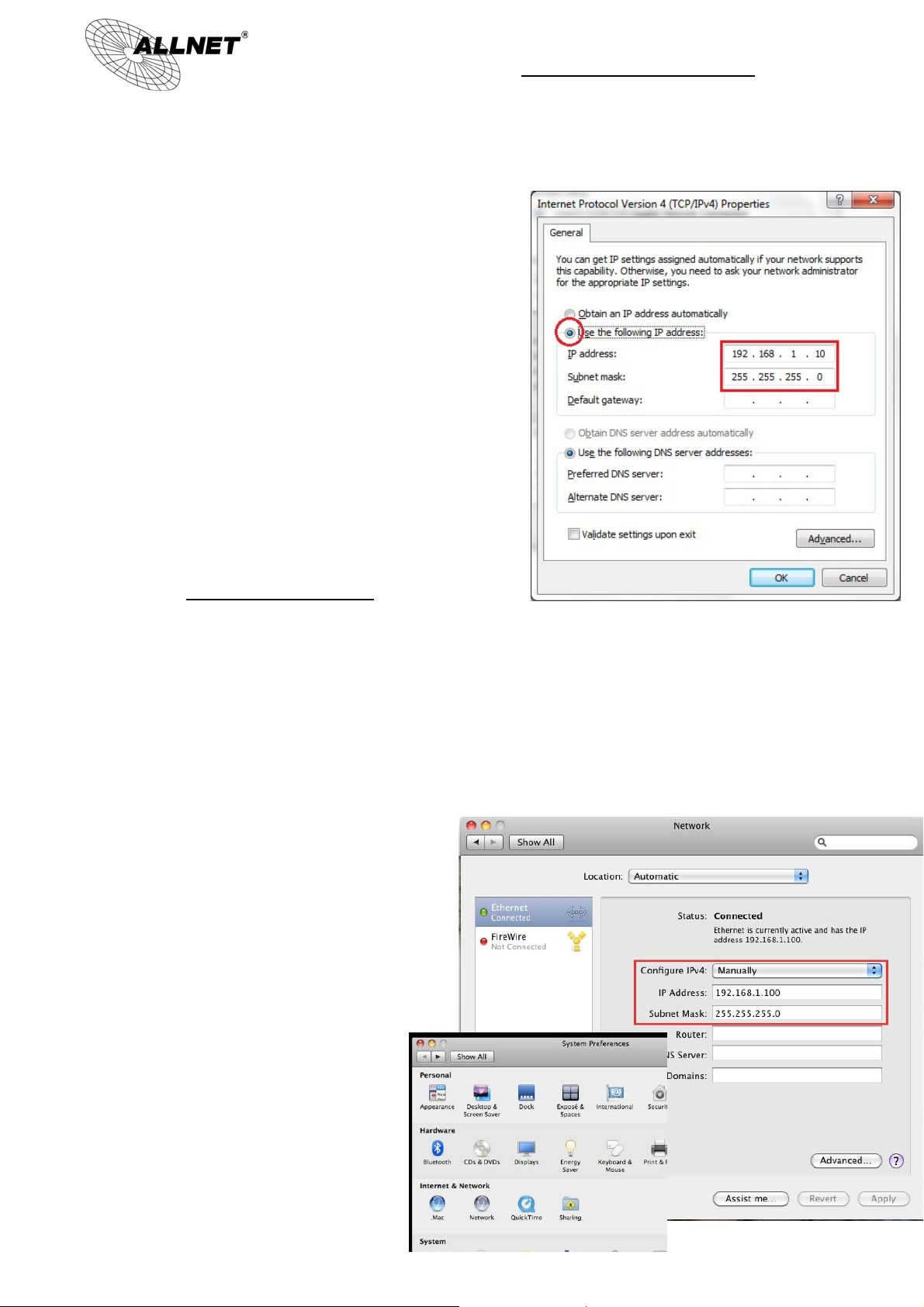
Select Use the following IP address and
enter IP address and subnet mask then press
OK.
Note: Ensure that the IP address and subnet
mask are on the same subnet as the device.
For example:
Device IP address: 192.168.1.1
PC IP address: 192.168.1.2 - 192.168.1.254
PC subnet mask: 255.255.255.0
ALL02850N User’s Manual
2.3 Apple Mac X OS
Open the System Preferences (can be opened in the Applications folder or
selecting it in the Apple Menu)
Select Network in the Internet & Network section
Highlight Ethernet
In Configure IPv4, select Manually
Enter IP address and subnet mask then press OK.
Note: Ensure that the IP address and subnet mask are on the same subnet as the
device.
For example:
Device IP address: 192.168.1.1
PC IP address: 192.168.1.2 -
192.168.1.254
PC subnet mask: 255.255.255.0
Click Apply when done.
11
Page 13
ALL02850N User’s Manual
2.4 Hardware Installation
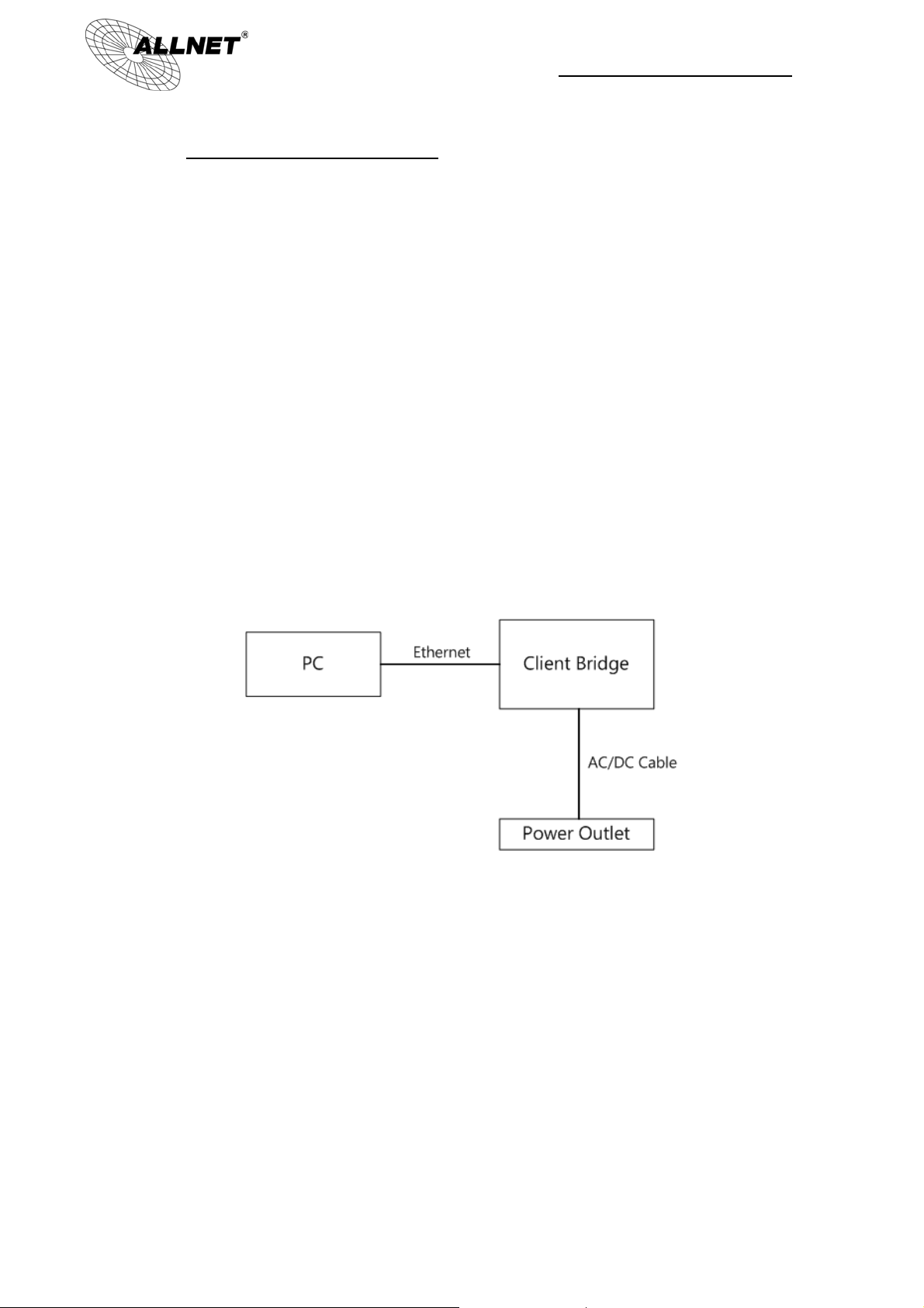
1) Ensure that the computer in use has an Ethernet Card (RJ-45 Ethernet Port). For
more information, verify with our computer user manual.
2) Connect one end of the Category 5 Ethernet cable into RJ-45 port of the
ALL02850N and the other end to the RJ-45 port on the computer that will use
the ALL02850N. Ensure that the cable is securely connected to both the
ALL02850N and the Computer.
3) Connect the Power Adaptor DC Inlet to the DC-IN port of the ALL02850N and
the Power Adaptor to the electrical out. Once both connections are secure, verify
the following:
a) Ensure that the Power light is on (it will be blue).
b) Ensure that the Wireless light is on (it will be blue).
c) Ensure that the LAN (Computer/ALL02850N Connection) light is on (it will
be blue).
d) Once all three lights are on, proceed to setting up the computer.
This diagram depicts the hardware configuration.
12
Page 14
ALL02850N User’s Manual
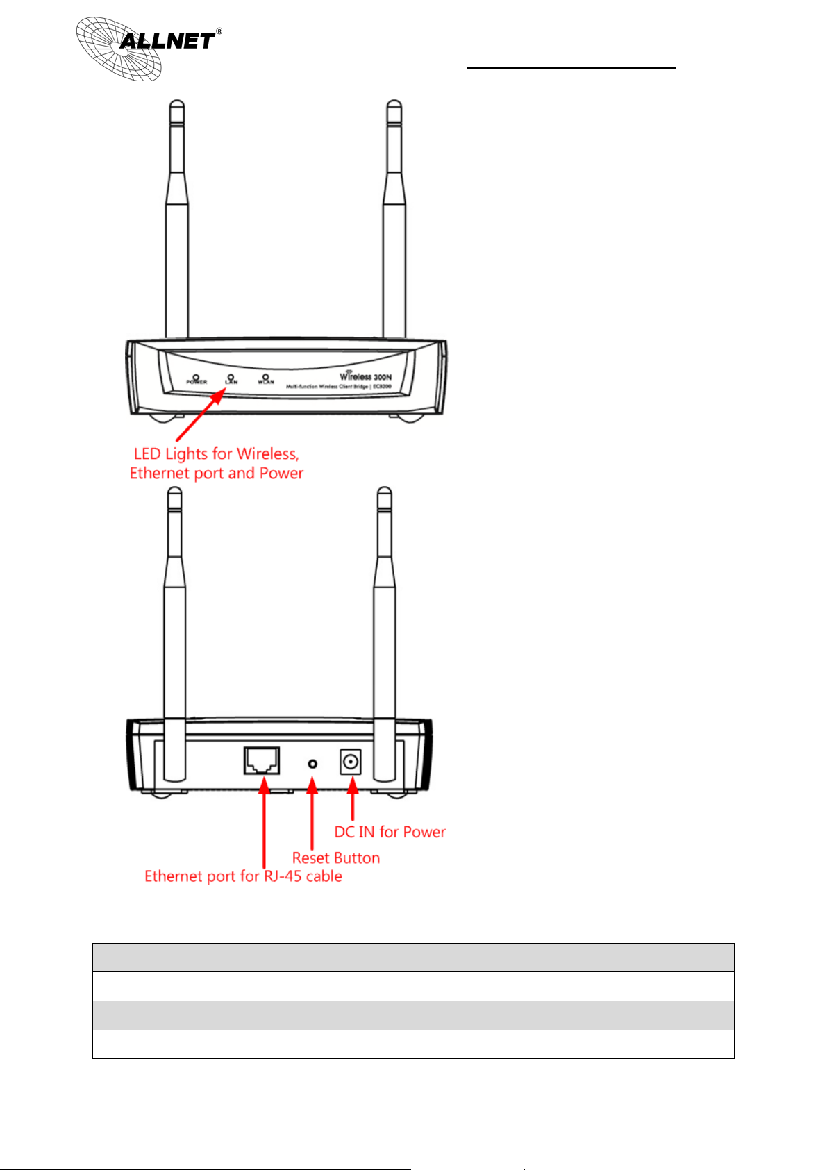
Front Panel
Rear Panel
Front Panel
LED Lights LED lights for Wireless, Ethernet port and Power.
Rear Panel
DC IN DC IN for Power.
13
Page 15

ALL02850N User’s Manual
Reset Button One click for reset the device. Press over 10 seconds for reset to factory
default.
Ethernet Port Ethernet port for RJ-45 cable.
3 Configuring Your Client Bridge
This section will show you how to configure the device using the web-based
configuration interface.
3.1 Default Settings
Please use your Ethernet port or wireless network adapter to connect the Client
Bridge.
Default Settings
IP Address 192.168.1.1
Username / Password admin / admin
Operation Mode Client Bridge
14
Page 16
ALL02850N User’s Manual
3.2 Web Configuration
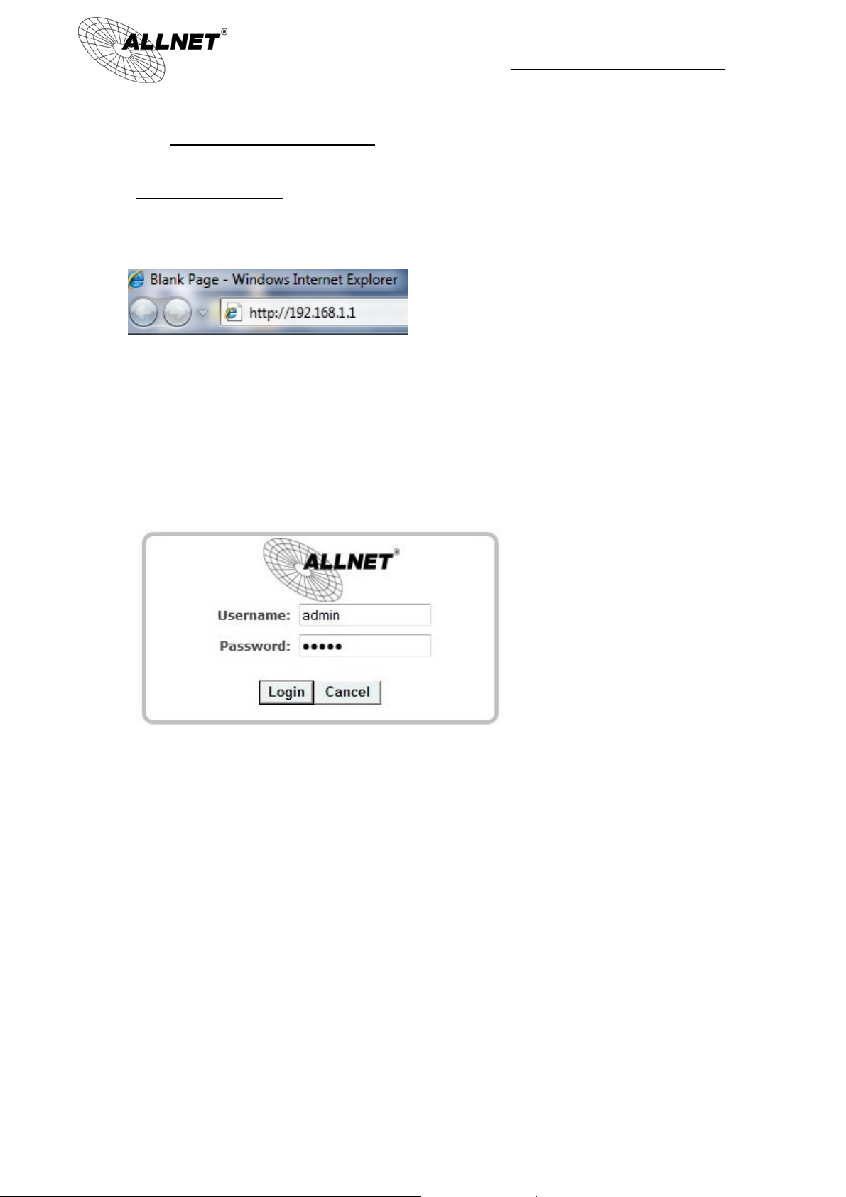
Open a web browser (Internet Explorer/Firefox/Safari) and enter the IP Address:
http://192.168.1.1
Note: If you have changed the default LAN IP Address of the device, ensure you enter the correct IP
Address.
The default username and password are admin. Once you have entered the
correct username and password, click the Login button to open the web-base
configuration page.
15
Page 17
ALL02850N User’s Manual
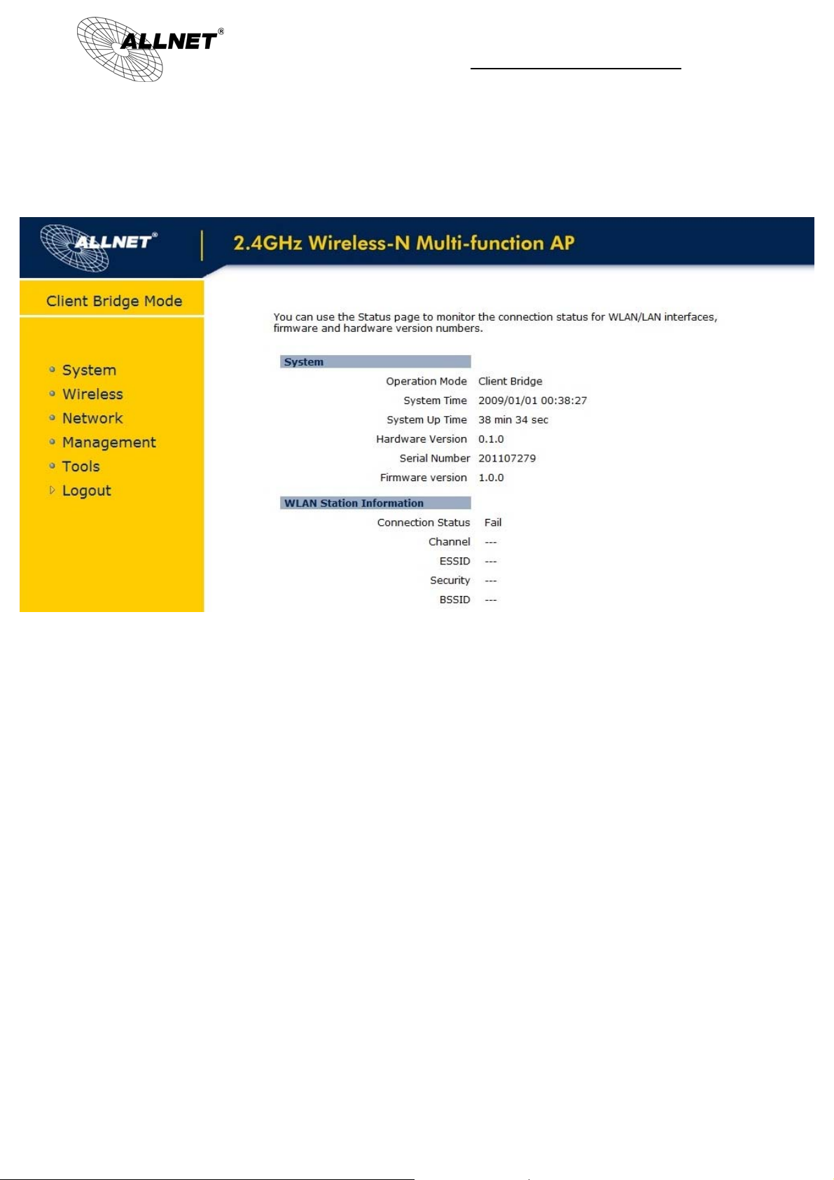
If successful, you will be logging in and see the ALL02850N User Menu
16
Page 18
ALL02850N User’s Manual
4 Building a Wireless Network
The ALL02850N has the ability to operate in various operating modes. The ALL02850N
is the ideal device in which you can build your WLAN. This chapter describes how to
build a WLAN around your ALL02850N using the operating modes of the ALL02850N.
4.1 Client Bridge Mode
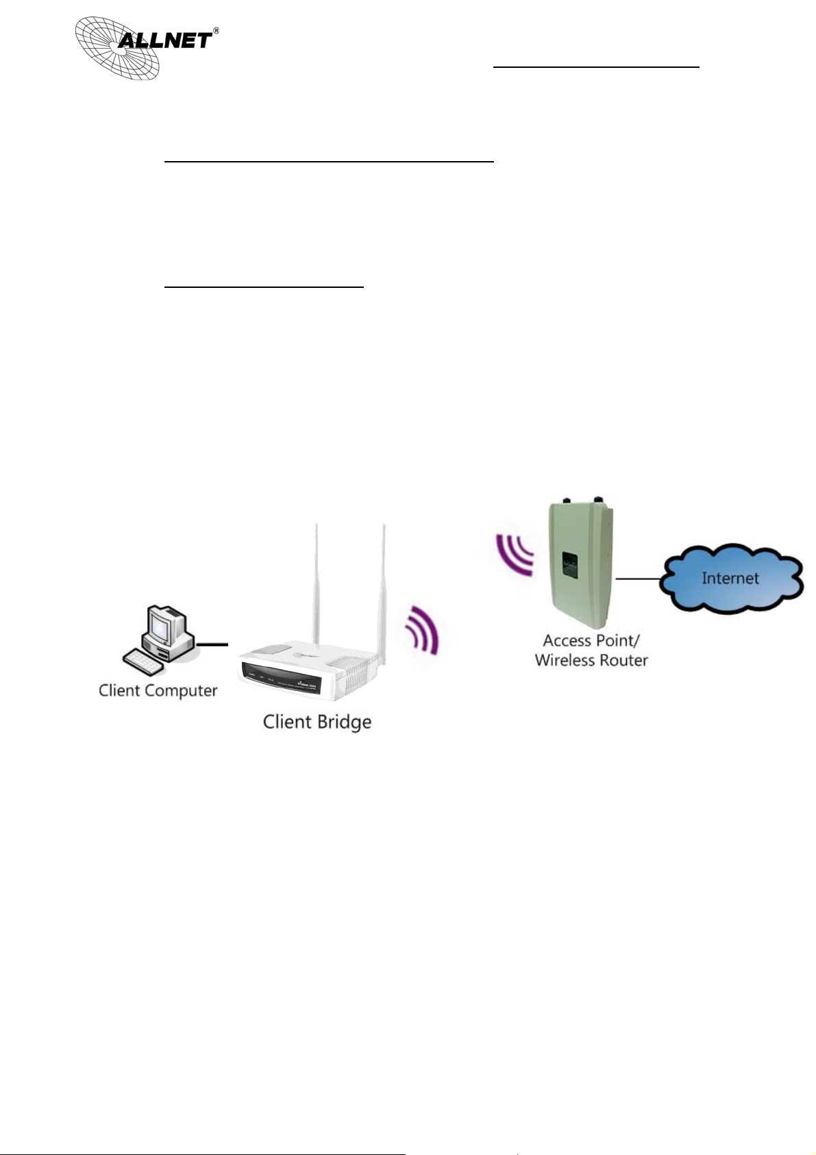
In Client Bridge Mode, the ALL02850N acts as a wireless dongle that connects to an
Access Point to allow a system wireless access to the network. This mode requires you
to connect the Ethernet port on your PC to the ALL02850N LAN port.
If you use the client bridge operating mode, use the ALL02850N Site Survey feature to
scan for Access Points within range. When you find an Access Point, configure the
ALL02850N to use the same SSID and Security Password as the Access Point to
associate with it.
17
Page 19
ALL02850N User’s Manual
4.2 Access Point Mode
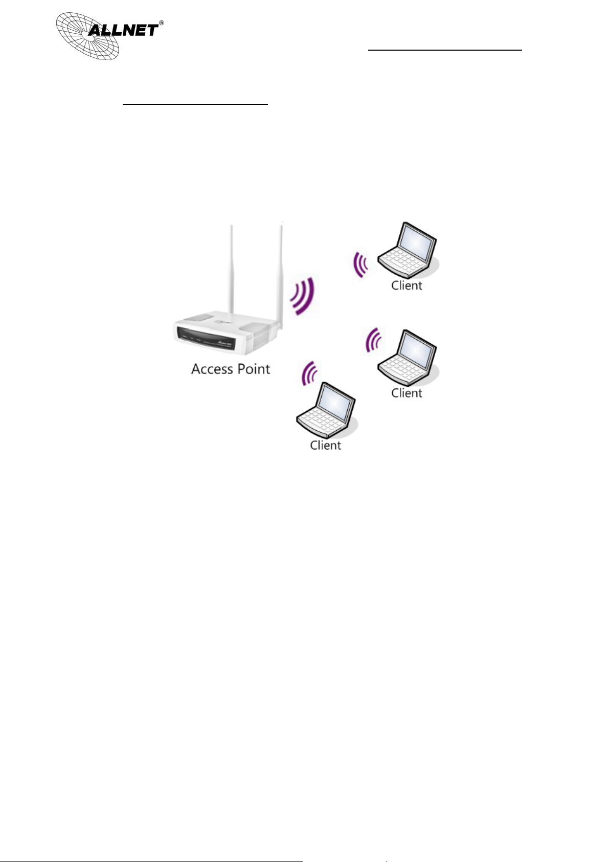
In Access Point Mode, ALL02850N behaves likes a central connection for stations or
clients that support IEEE 802.11b/g/n networks. The stations and clients must be
configured to use the same SSID and security password to associate with the
ALL02850N. The ALL02850N supports up to four SSIDs at the same time for secure
guest access.
18
Page 20
ALL02850N User’s Manual
4.3 WDS AP Mode
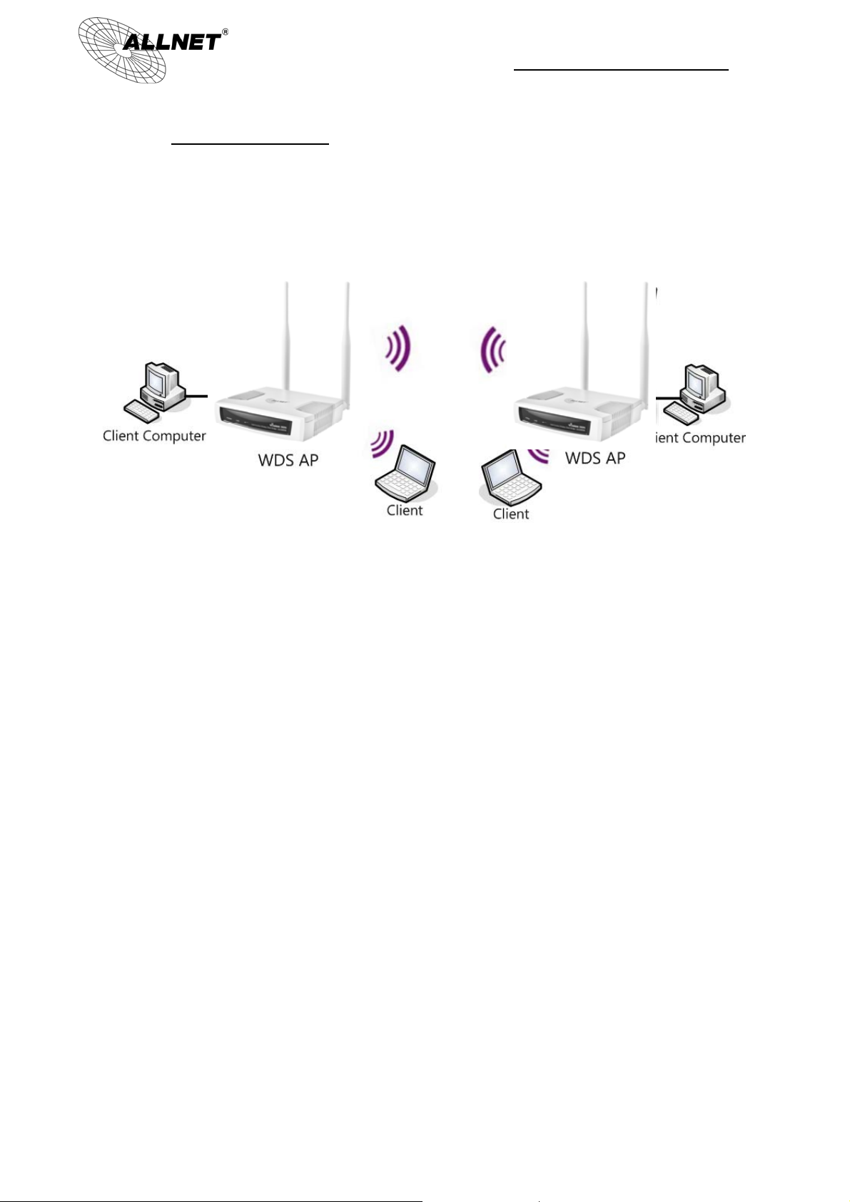
The ALL02850N also supports WDS AP mode. This operating mode allows wireless
connections to the ALL02850N using WDS technology. In this mode, configure the
MAC addresses in both Access Points to enlarge the wireless area by enabling WDS
Link settings. WDS supports four AP MAC addresses.
19
Page 21
ALL02850N User’s Manual
4.4 WDS Bridge Mode
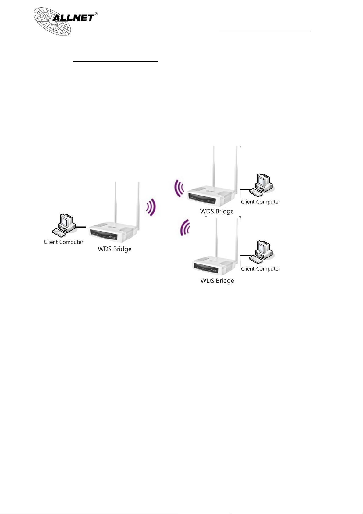
In WDS Bridge Mode, the ALL02850N can wirelessly connect different LANs by
configuring the MAC address and security settings of each ALL02850N device. Use
this mode when two wired LANs located a small distance apart want to communicate
with each other. The best solution is to use the ALL02850N to wirelessly connect two
wired LANs, as shown in the following figure.
WDS Bridge Mode can establish four WDS links, creating a star-like network.
Note: WDS Bridge Mode does not act as an Access Point. Access Points linked by WDS are using
the same frequency channel. More Access Points connected together may lower throughput.
Please be aware to avoid loops in your wireless connection, otherwise enable Spanning Tree
Function.
20
Page 22
ALL02850N User’s Manual
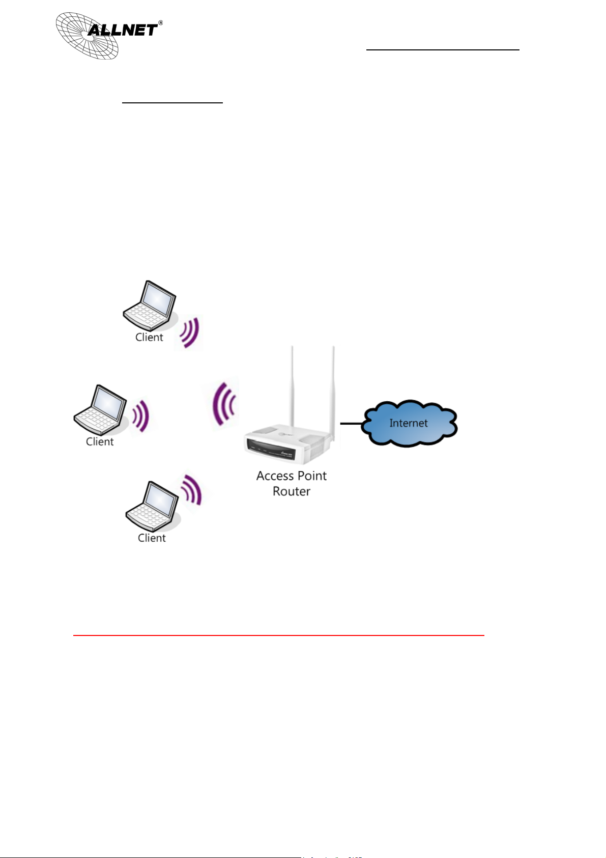
4.5 Router Mode
In Access Point Router Mode, ALL02850N grants Internet access to multiple wireless
clients. In this mode, the ALL02850N’s internal Dynamic Host Configuration Protocol
(DHCP) server automatically allocates ranges of IP addresses to each wireless client
that will access the Internet through the ALL02850N.
This mode requires you to connect the ALL02850N’s Ethernet port to a modem or
router. And the wireless clients must be configured to use the same SSID and security
password to associate with the ALL02850N. The ALL02850N supports up to four SSIDs
at the same time for secure guest access.
Please Note:
You have to configure WLAN interface before you change to this mode.
After you change to Access Point Router-mode, you have to connect via WLAN to
the ALL02850N, because the device will change the LAN Port to WAN Port with
an dynamic IP-address configuration (DHCP).
This means you can’t connect to the device via LAN anymore, only with WLAN.
21
Page 23
ALL02850N User’s Manual
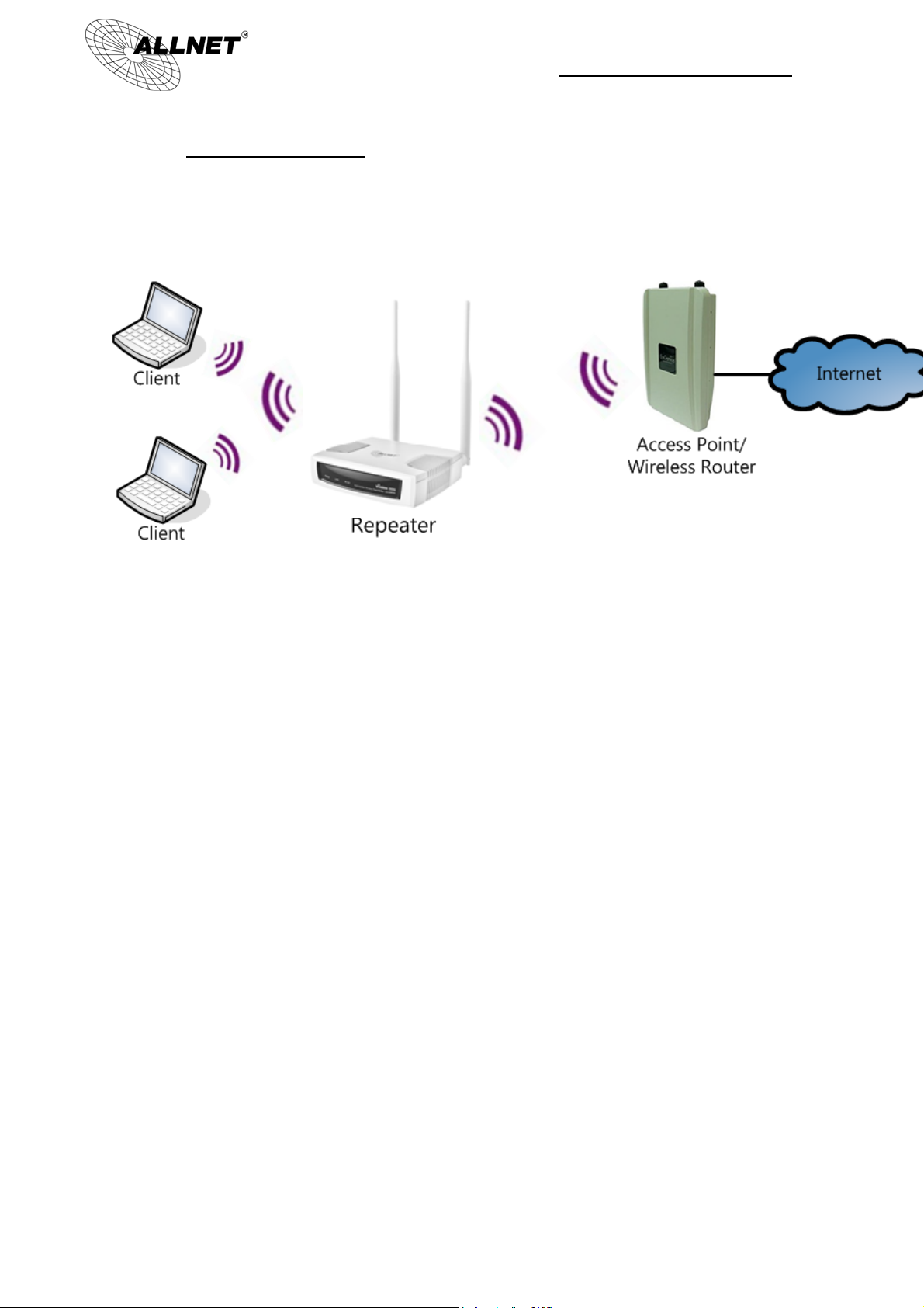
4.6 Repeater Mode
Repeater is used to regenerate or replicate signals that are weakened or distorted by
transmission over long distances and through areas with high levels of
electromagnetic interference (EMI).
22
Page 24
ALL02850N User’s Manual
5 System
5.1 Operation Mode
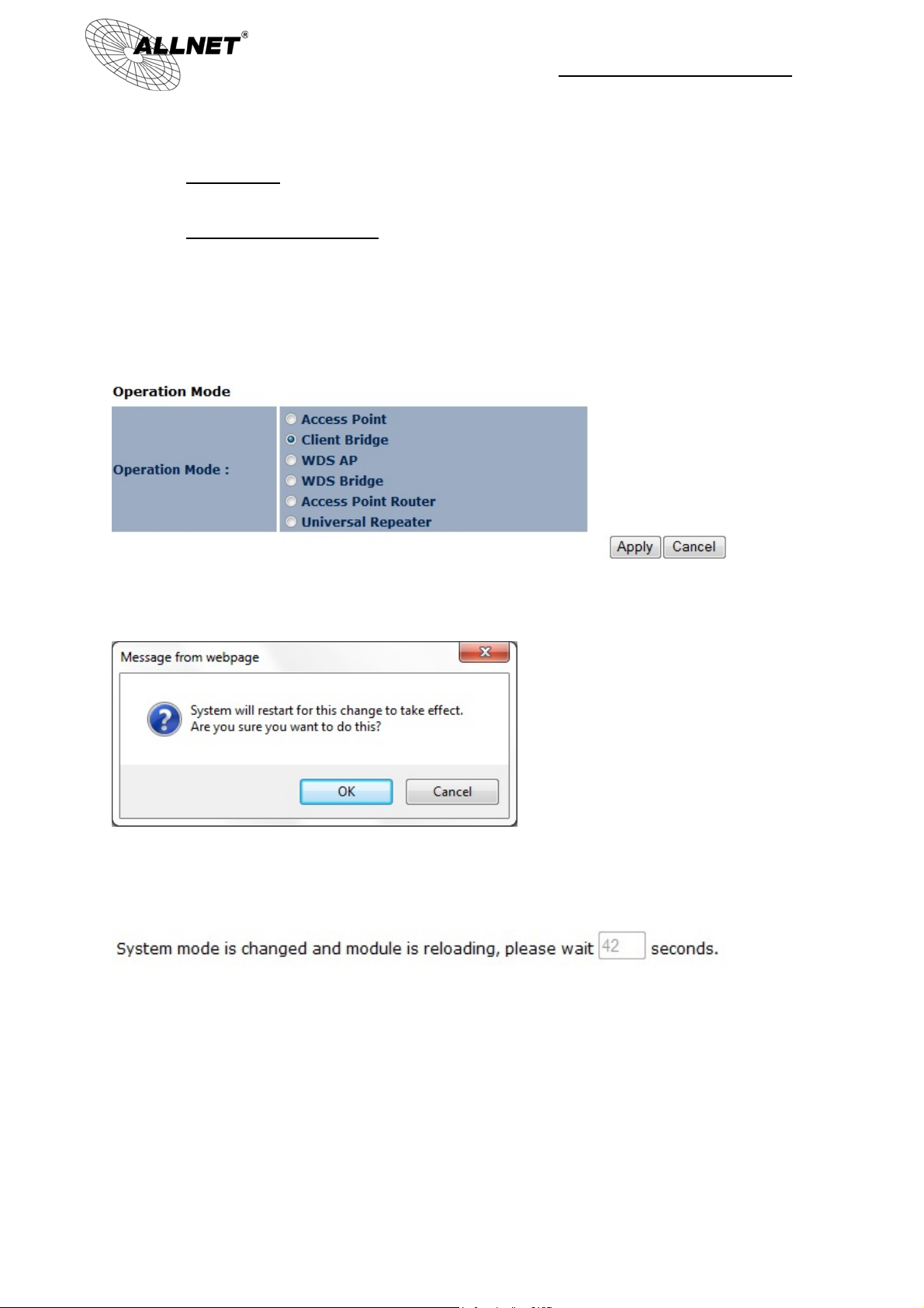
Each operating mode offers different features. In order to switch the operating mode,
select it from the Operation Mode from the System Menu. There are six operation
modes: Access Point, Client Bridge, WDS AP, WDS Bridge, Access Point Router
and Universal Repeater.
A dialog box will appear to notify you that the system will restart in order for the
changes to take effect. Click on the OK button to continue.
The ALL02850N will display how much time it will take to restart the device in the new
operating mode as shown below.
23
Page 25
ALL02850N User’s Manual
5.2 Status
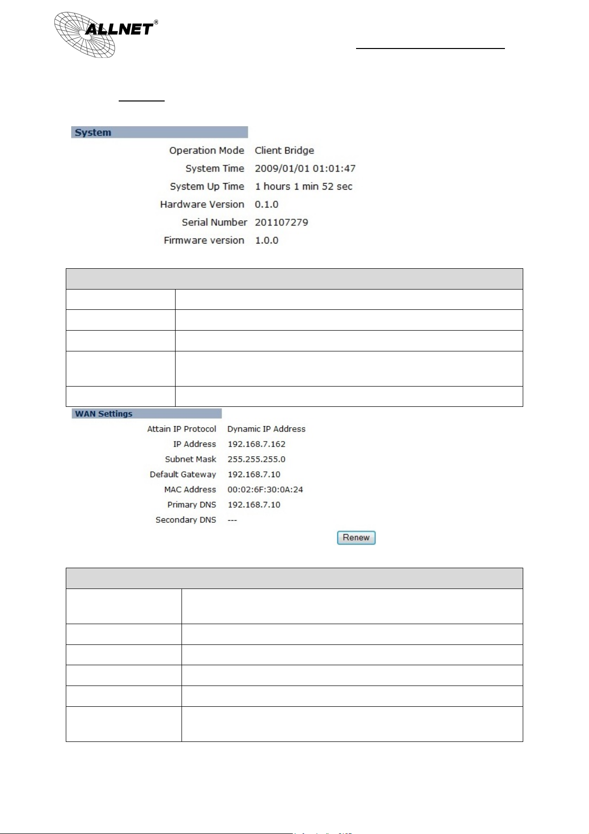
This page will display status of the device.
System
Operation Mode Displays the current mode of operation of the ALL02850N.
System Time Displays the current time of the ALL02850N.
System Up Time The elapsed time of operation of the ALL02850N.
Hardware Version
and Serial Number
Firmware Version The current firmware version of the ALL02850N.
Hardware information of the ALL02850N.
WAN Settings (Router mode)
Attain IP Protocol Method used to connect to the Internet. This is your WAN connection
type.
IP Address The WAN IP address of the Router.
Subnet Mask The WAN subnet mask of the Router.
Default Gateway The default gateway of the Router.
MAC Address The WAN MAC address of the Router.
Primary and
Secondary DNS
The IP addresses of the Primary and Secondary DNS servers assigned
to the WAN connection.
24
Page 26
ALL02850N User’s Manual
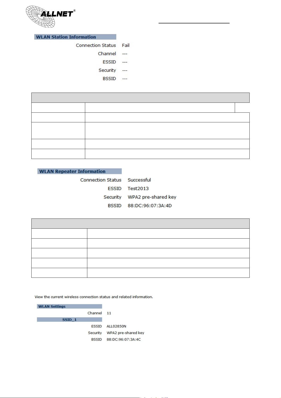
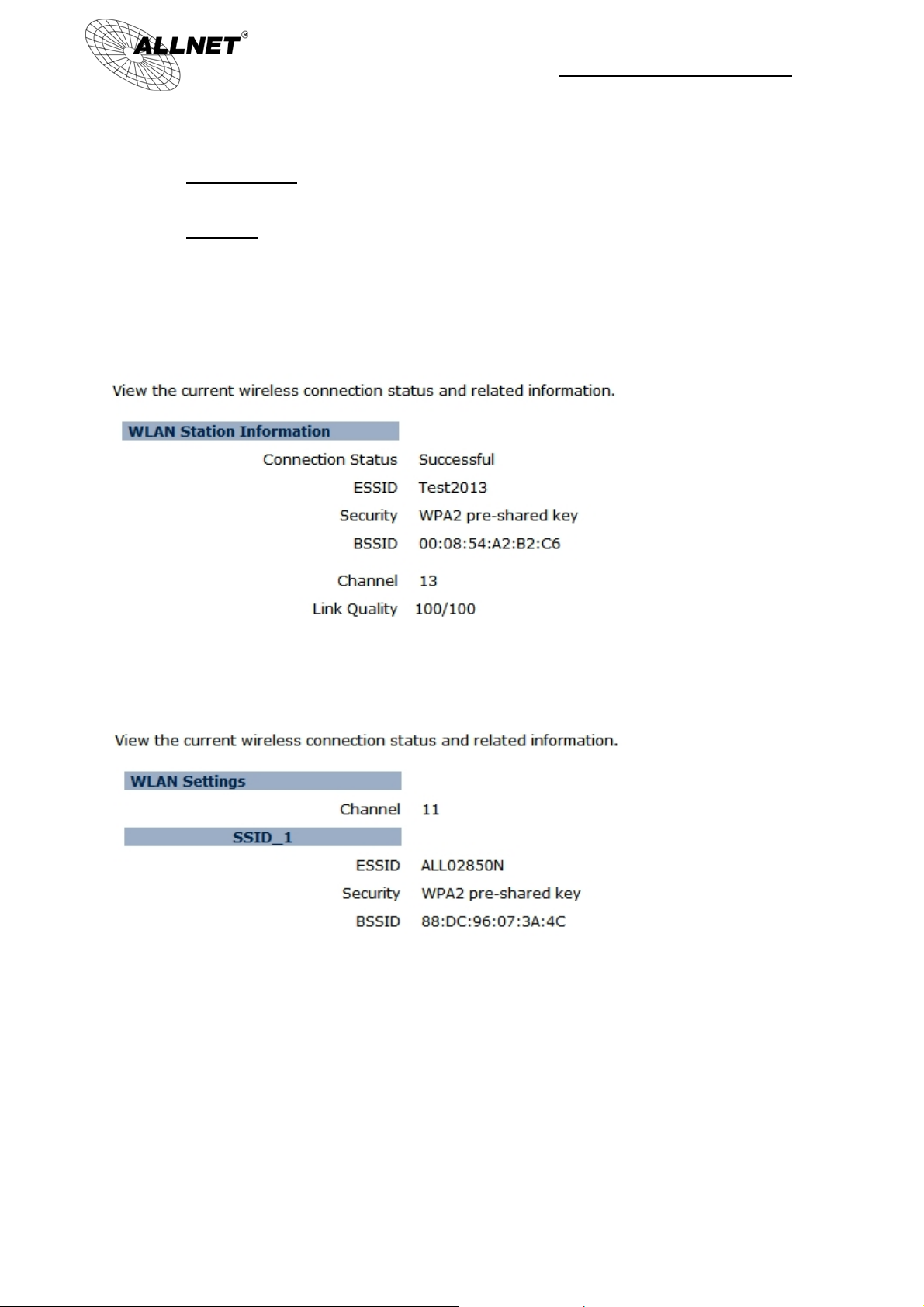
WLAN Station Information (Client Bridge mode)
Connection Status The connection status: Successful or Fail.
Channel The wireless channel in use.
ESSID The SSID (Network Name) of the wireless network which ALL02850N
connected.
Security The wireless encryption in use.
BSSID The MAC address of this SSID which ALL02850N connected.
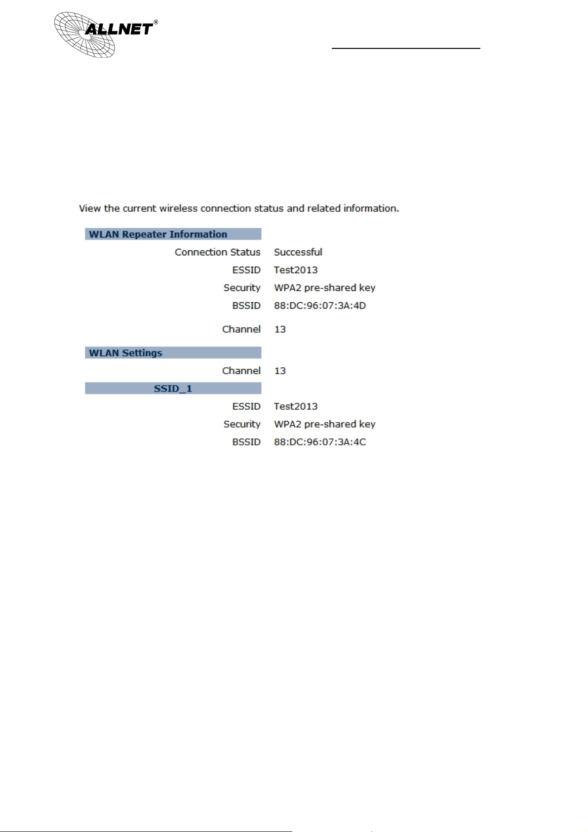
WLAN Repeater Information (Repeater mode)
Connection Status The connection status: Successful or Fail.
Channel The wireless channel in use.
ESSID The SSID (Network Name) of the wireless network.
Security Wireless encryption for this SSID.
BSSID The MAC address of this SSID.
25
Page 27

ALL02850N User’s Manual
WLAN Settings (Access Point / WDS AP / Repeater / Router mode)
Channel Displays the current Wireless Channel in use by the ALL02850N.
ESSID The SSID (Network Name) of the wireless network (up to 4 SSIDs
supported).
Security Current wireless encryption for the corresponding SSID.
BSSID The MAC address of the corresponding SSID.
26
Page 28
ALL02850N User’s Manual
5.3 DHCP
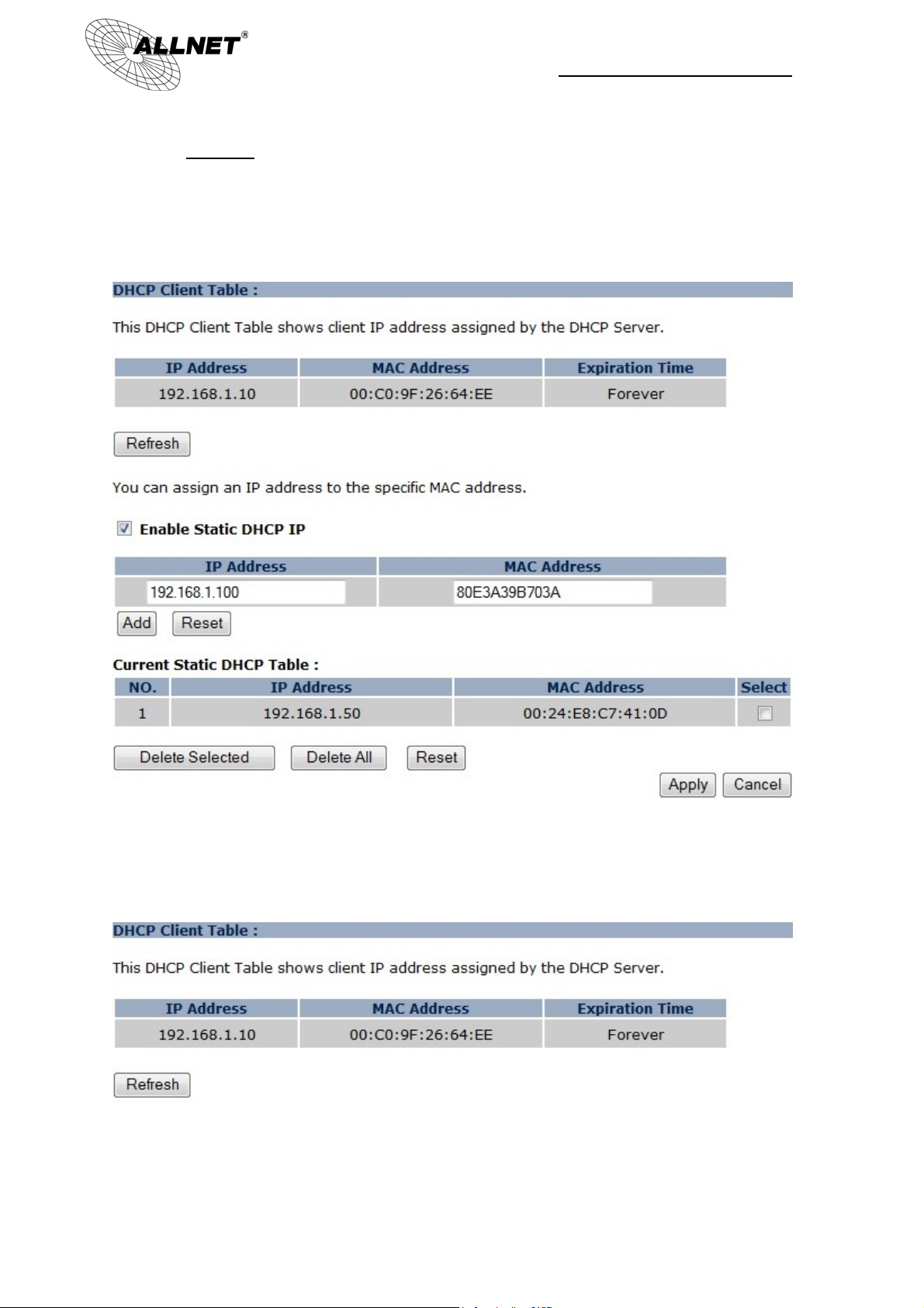
The DHCP option in the System menu displays the client IP address assigned by the
DHCP Server. You can also set the IP Addresses of the connected devices manually.
Note: Only in Access Point / Router mode.
The DHCP Client Table shows the LAN clients that have been allocated an IP address
from the DHCP Server.
27
Page 29

ALL02850N User’s Manual
DHCP Client Table
IP address Displays the IP Address of the client on the LAN.
MAC address Displays the MAC Address of the client on the LAN.
Expiration Time Displays the time of expiration of the IP Address of the client.
Refresh Click this button to update the DHCP Client Table.
28
Page 30
ALL02850N User’s Manual
5.4 Schedule
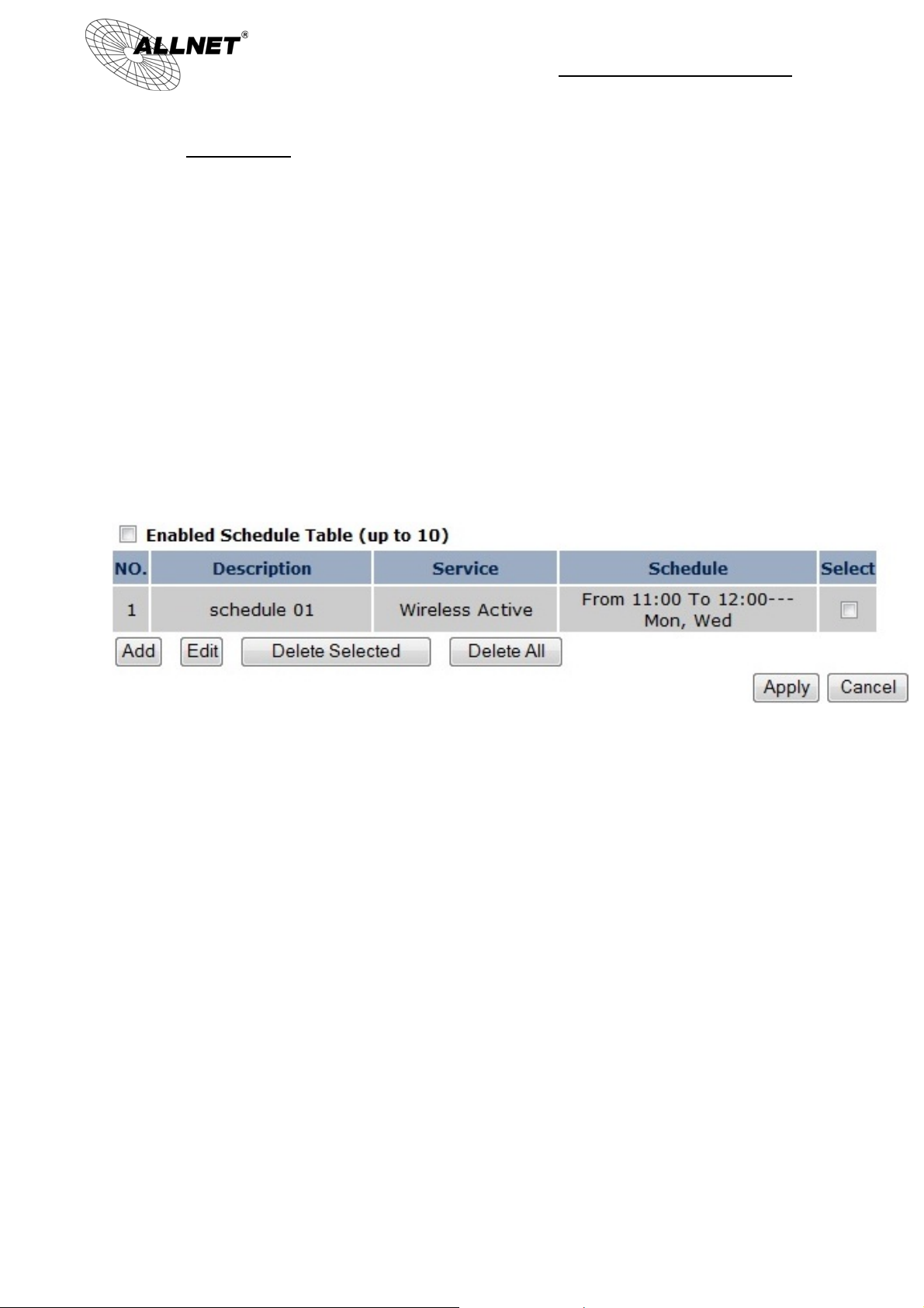
The Schedule option of the System menu allows you to set a schedule when the
ALL02850N’s Wireless is active.
The Schedule Table will display:
NO.: The entry number of the schedule.
Description: The name given to the schedule.
Service: Displays whether the wireless service will be activate or not during the
scheduled time.
Schedule: Displays when the schedule will execute.
You will also be able to Add new schedules (at most 10), Edit schedules, Delete
Selected schedules, or Delete All schedules.
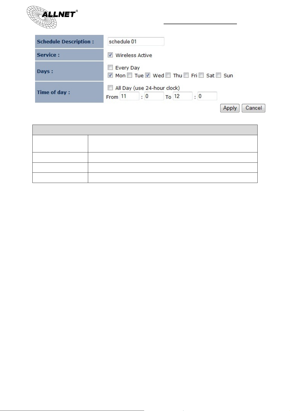
After selecting Add or Edit, the following form will show up. Fill in the form to set the
schedule you want.
29
Page 31
Schedule
ALL02850N User’s Manual
Schedule
Description
Service The service provided for the schedule.
Days Set which days the schedule will be active.
Time of day Set what time of the selected days the schedule will be active.
Assign a name to the schedule.
30
Page 32
ALL02850N User’s Manual
5.5 Event Log
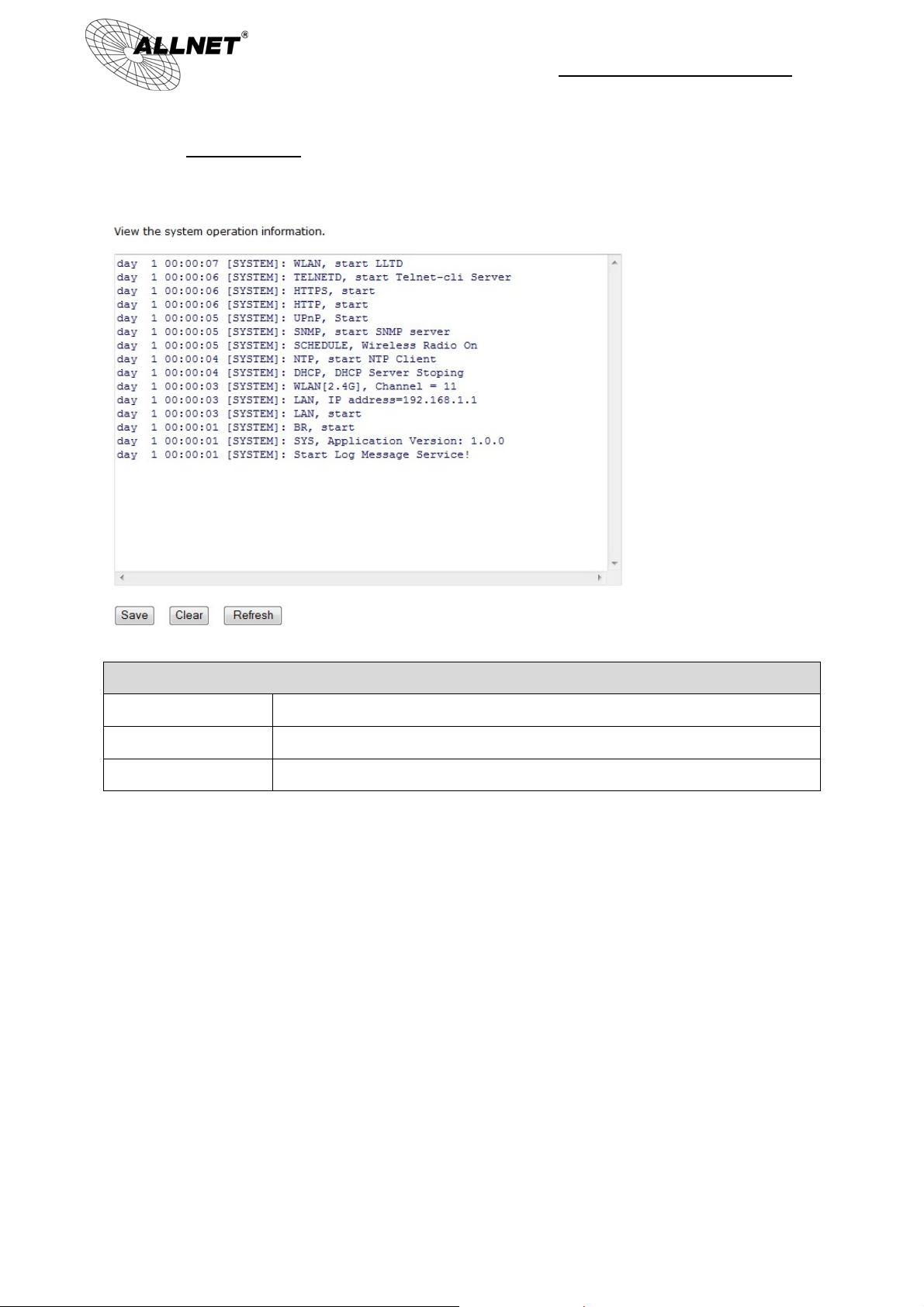
The Event Log of the System menu displays the system events and actions of the
ALL02850N. When powered down or rebooted, the Event Log will be cleared.
Event Log
Save Save the log to a .txt file.
Clear Clear the log.
Refresh Update the log.
31
Page 33
ALL02850N User’s Manual
5.6 Monitor
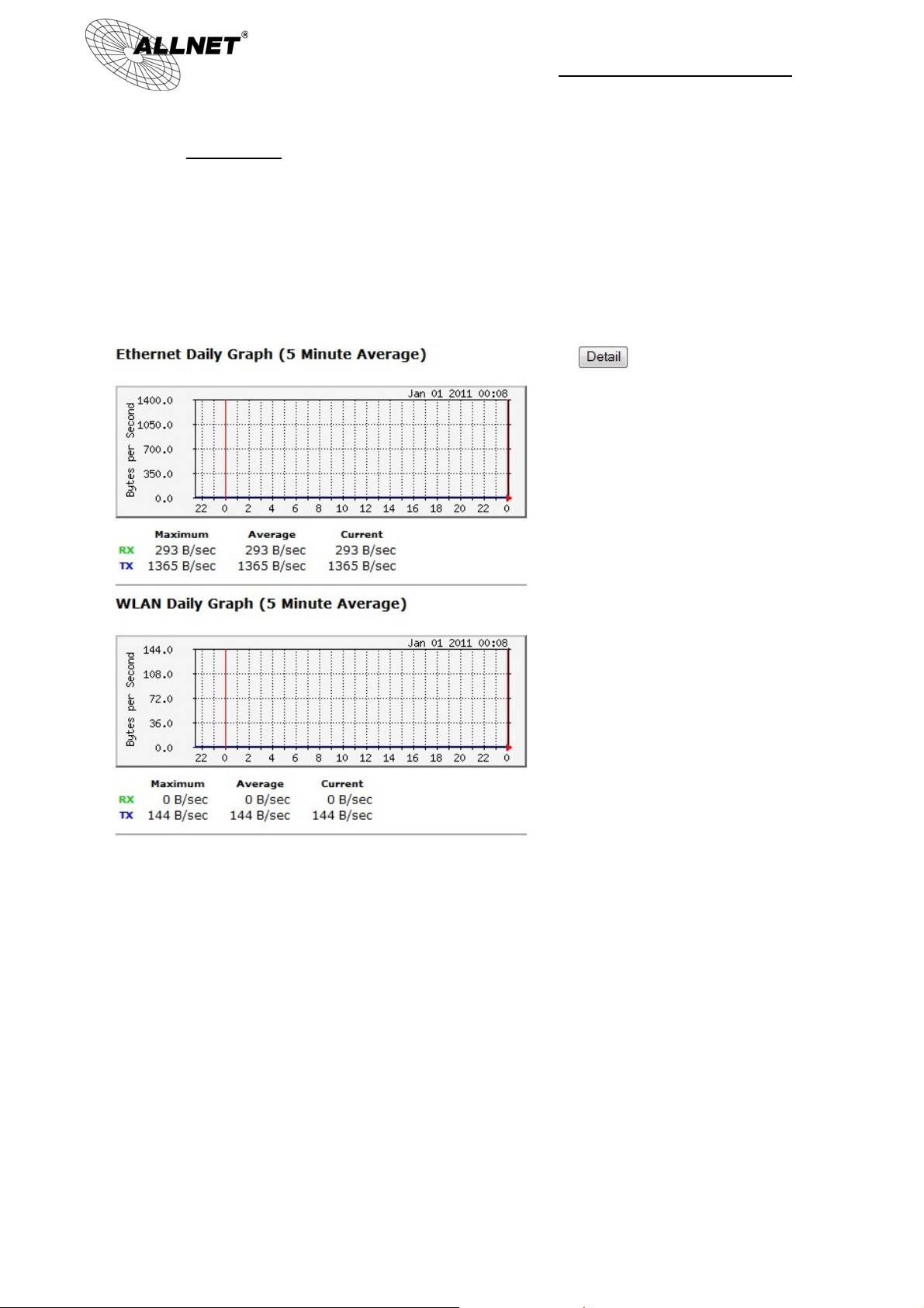
The Monitor option of the System menu displays 2 histogram graphs. The
histograms represent the bandwidth usage of both the daily use of the Ethernet and
the daily use of the WLAN. If you click on Detail, a new browser window will open
with 4 additional histograms (6 total). In the new browser window, you will be able to
view the weekly and monthly bandwidth usage for both the Ethernet and WLAN.
32
Page 34
ALL02850N User’s Manual
6 Wireless
6.1 Status
The Status of the Wireless menu displays the current status of the ALL02850N's
wireless configuration.
Client Bridge mode:
Access Point / Router mode:
33
Page 35
Repeater mode:
ALL02850N User’s Manual
34
Page 36
ALL02850N User’s Manual
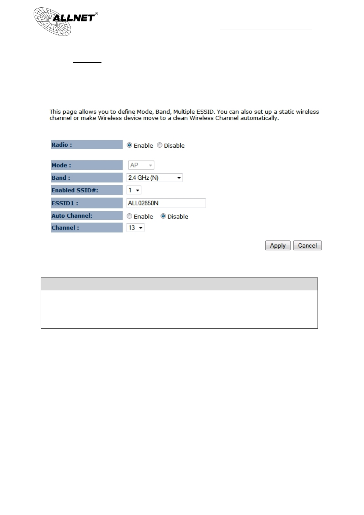
6.2 Basic
The Basic option of the Wireless menu displays the basic wireless options of the
ALL02850N.
Client Bridge:
Basic (Client Bridge mode)
Radio Enable or Disable the device’s wireless signal.
Band Select the types of wireless clients that the device will accept.
Site Survey Click on [Site Survey] to search the existing AP.
35
Page 37
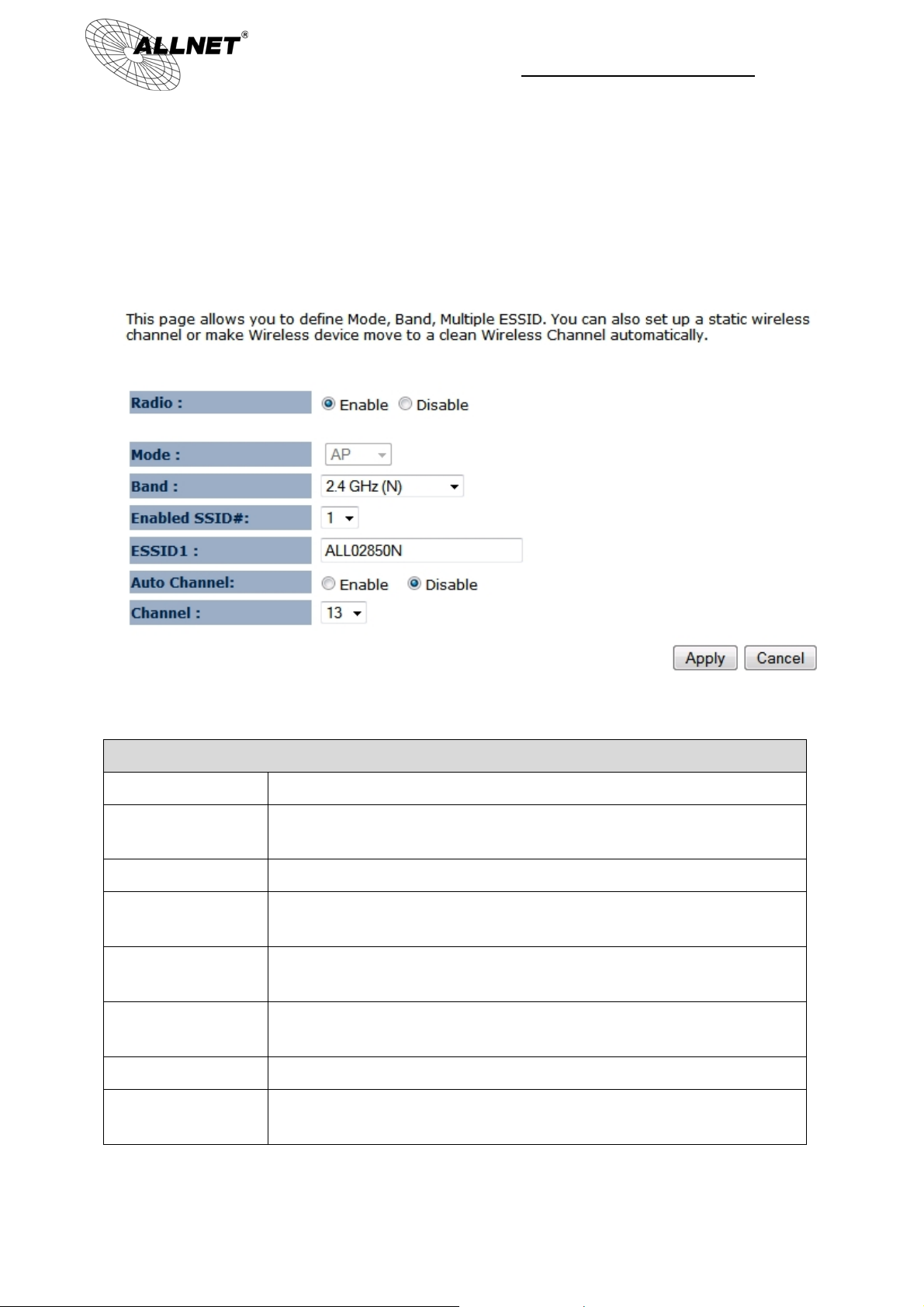
Access Point / Router mode:
ALL02850N User’s Manual
Basic (Access Point / Router mode)
Radio Enable or Disable the ALL02850N’s wireless signal.
Mode Select between Access Point or Wireless Distribution System (WDS)
modes.
Band Select the types of wireless clients that the device will accept.
Enable SSID# Select the number of SSID’s (Wireless Network names) you would like
(up to 4).
SSID# Enter the name of your wireless network. You can use up to 32
characters.
Auto Channel When enabled, the device will scan the wireless signals around your
area and select the channel with the least interference.
Channel Manually select which channel the wireless signal will use.
Check Channel
Time
When Auto Channel is Enabled, you can specify the period of device
will scan the wireless signals around your area.
36
Page 38
ALL02850N User’s Manual
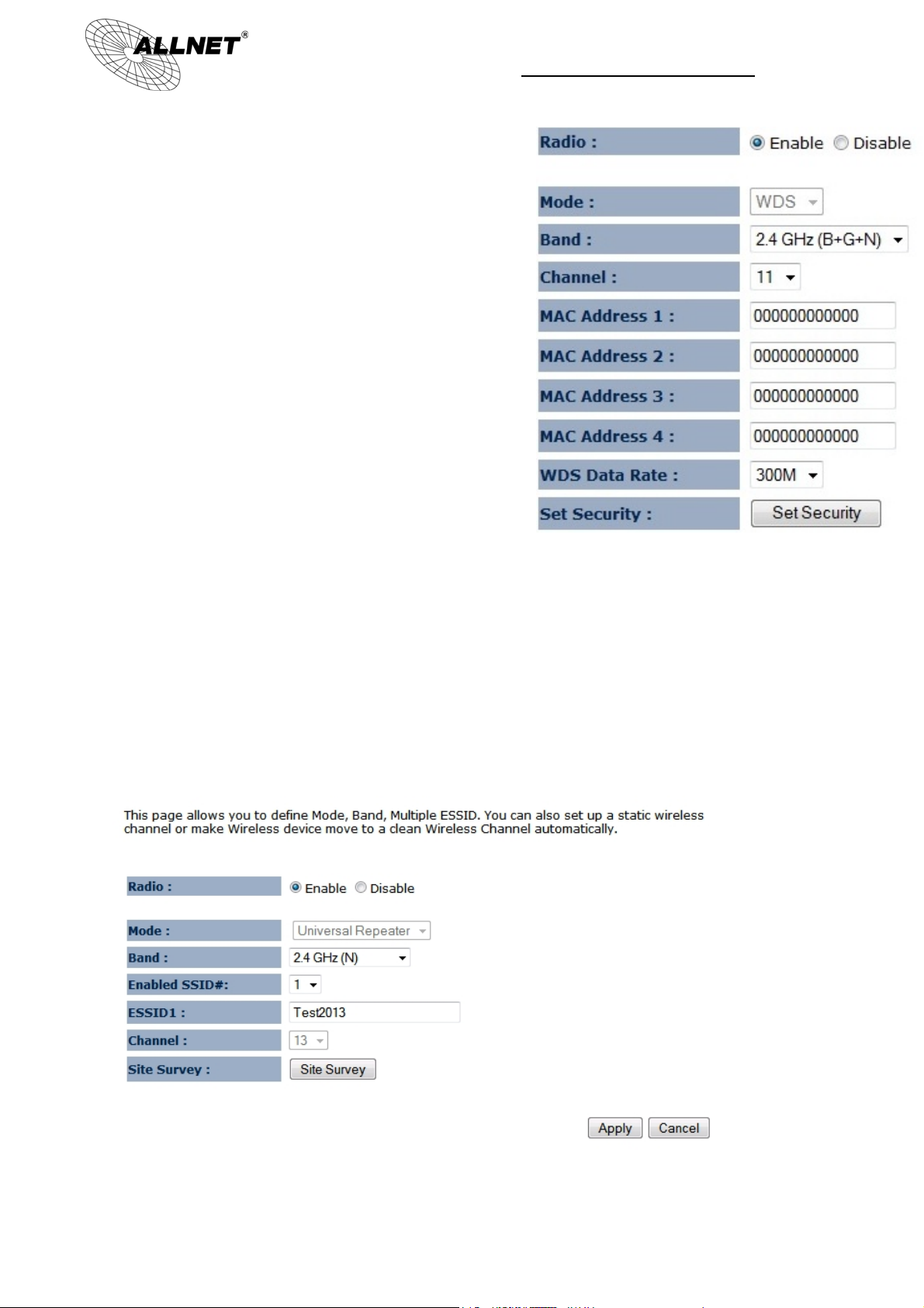
WDS AP / WDS Bridge mode:
Wireless Distribution System (WDS)
Using a WDS to connect Access Points wirelessly
extends a wired infrastructure to locations where
cabling is not possible or inefficient to implement.
Note: Compatibility between different brands and
models of Access Points is not guaranteed. It is
recommended that a WDS network be created
using the same Access Point models for maximum
compatibility.
Also, all Access Points in the WDS network need
to use the same Channel and Security settings.
To create a WDS network, please enter the MAC
addresses of the Access Points that you want
included in the WDS. There can be a maximum of
four access points.
Repeater mode:
37
Page 39

ALL02850N User’s Manual
Basic (Repeater mode)
Radio Enable or Disable the device’s wireless signal.
Band Select the types of wireless clients that the device will accept.
eg: 2.4 Ghz (B+G)
Only 802.11b and 11g clients will be allowed.
ESSID1 Enter the name of your wireless network. You can use up to 32
characters.
Site Survey Click on [Site Survey] to search the existing AP.
38
Page 40
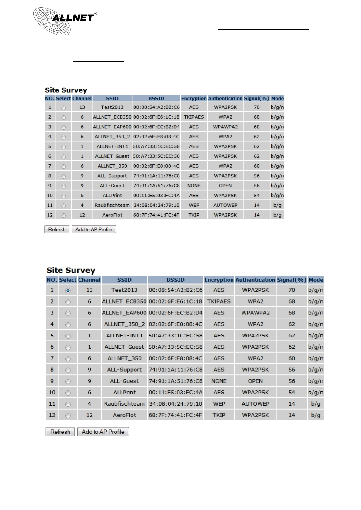
6.3 Site Survey
Client Bridge mode:
1. AP list after site survey.
ALL02850N User’s Manual
2. Select an AP and click on [Add to AP Profile].
39
Page 41
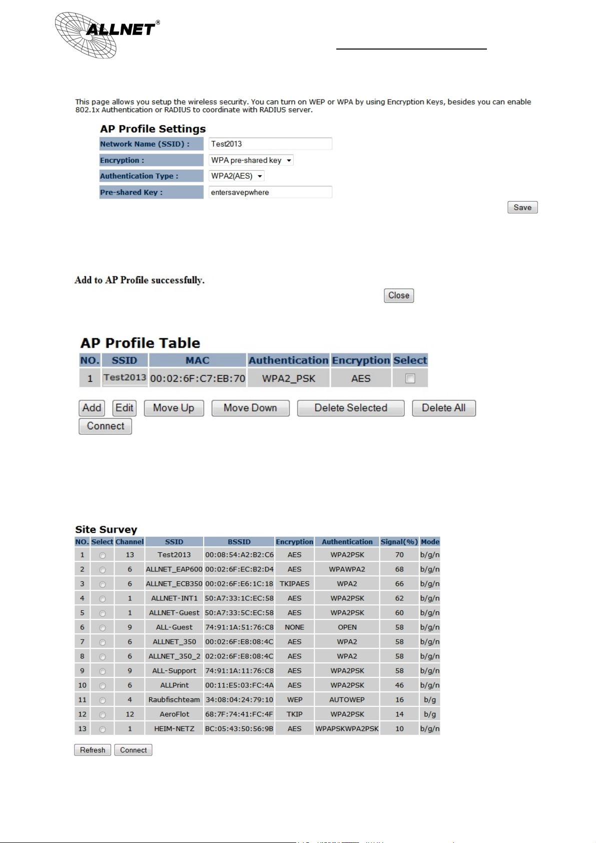
ALL02850N User’s Manual
3. Enter the correct security setting.
4. Add AP profile successfully, click on [Close] to close the
browser.
5. The AP profile is added in AP Profile Table.
Repeater mode:
1. AP list after site survey.
40
Page 42
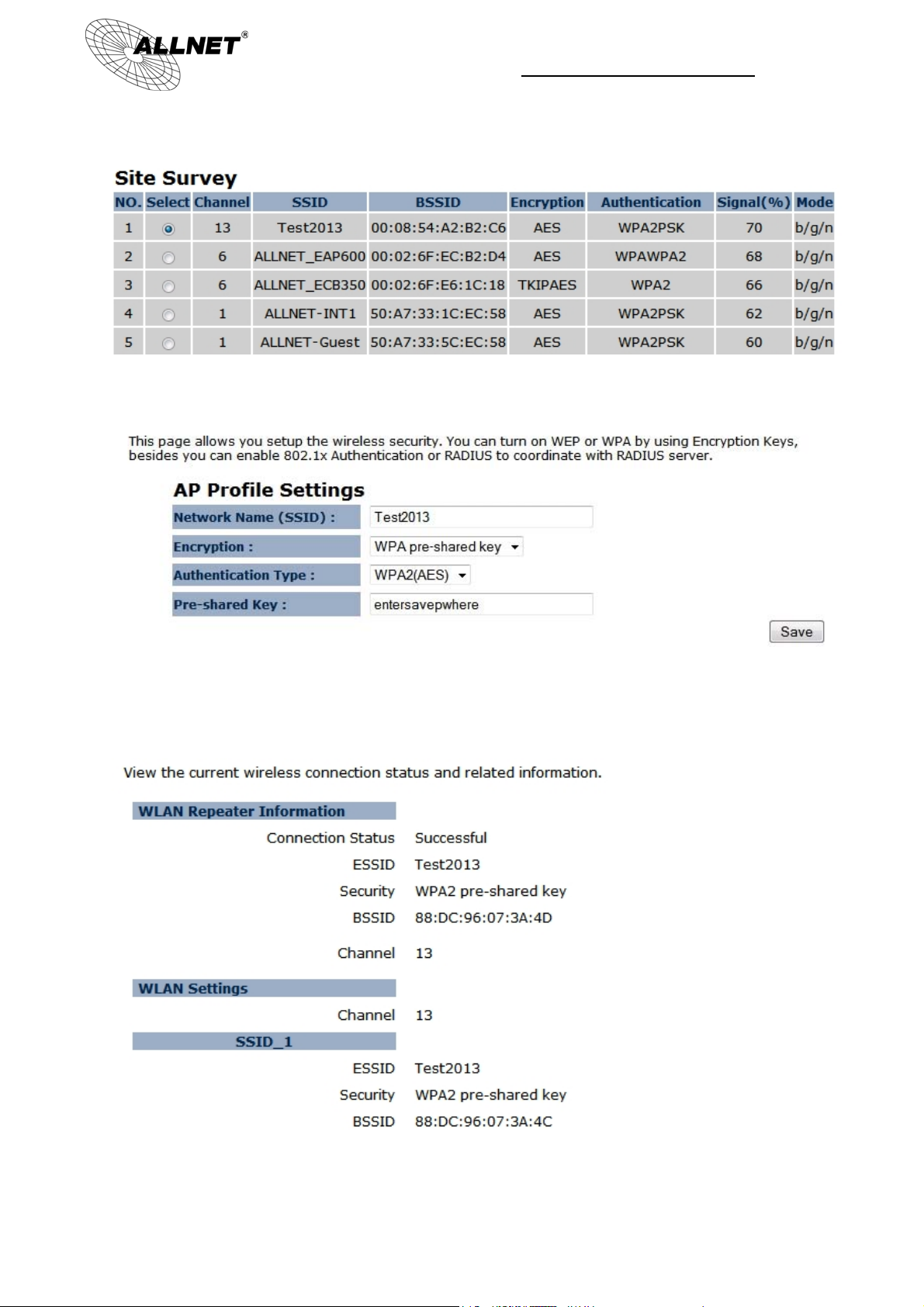
2. Select an AP and click on [Connect].
3. Enter the correct security setting.
ALL02850N User’s Manual
4. Connect AP successfully, click on [Close] to close the browser.
5. You can see the Connection Status in Status WEB page.
41
Page 43
ALL02850N User’s
Manual
6.4 Advanced
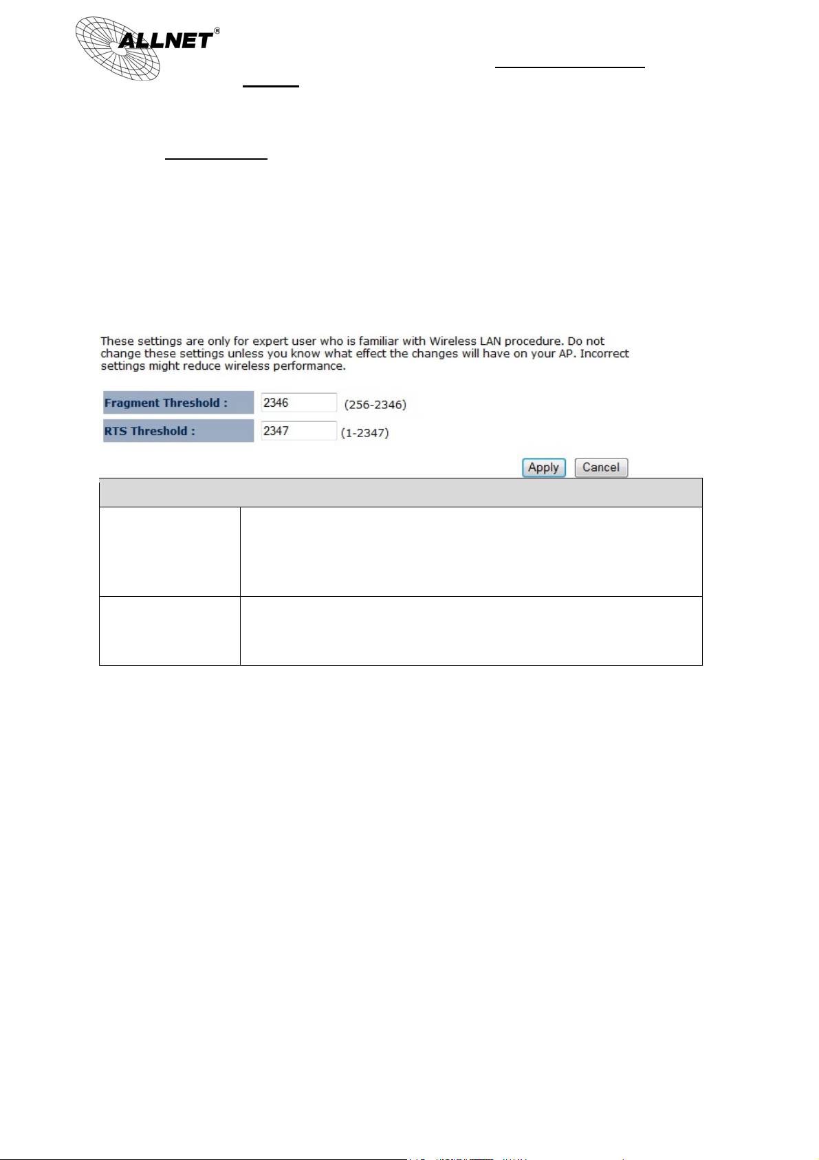
The Advanced option of the Wireless menu displays the advanced wireless
options of the ALL02850N.
It is recommended that the ALL02850N’s default settings are used unless the user
has experience with advanced networking.
Client Bridge mode:
Advanced (Client Bridge mode)
Fragment
Threshold
RTS Threshold When the packet size is smaller than the RTS Threshold, the packet
Specifies the maximum size of the packet per fragment. This
function can reduce the chance of packet collision.
However, when the fragment threshold is set too low, there will be
increased overhead resulting in poor performance.
will be sent without an RTS/CTS handshake, which may result in
incorrect transmission.
42
Page 44
ALL02850N User’s Manual
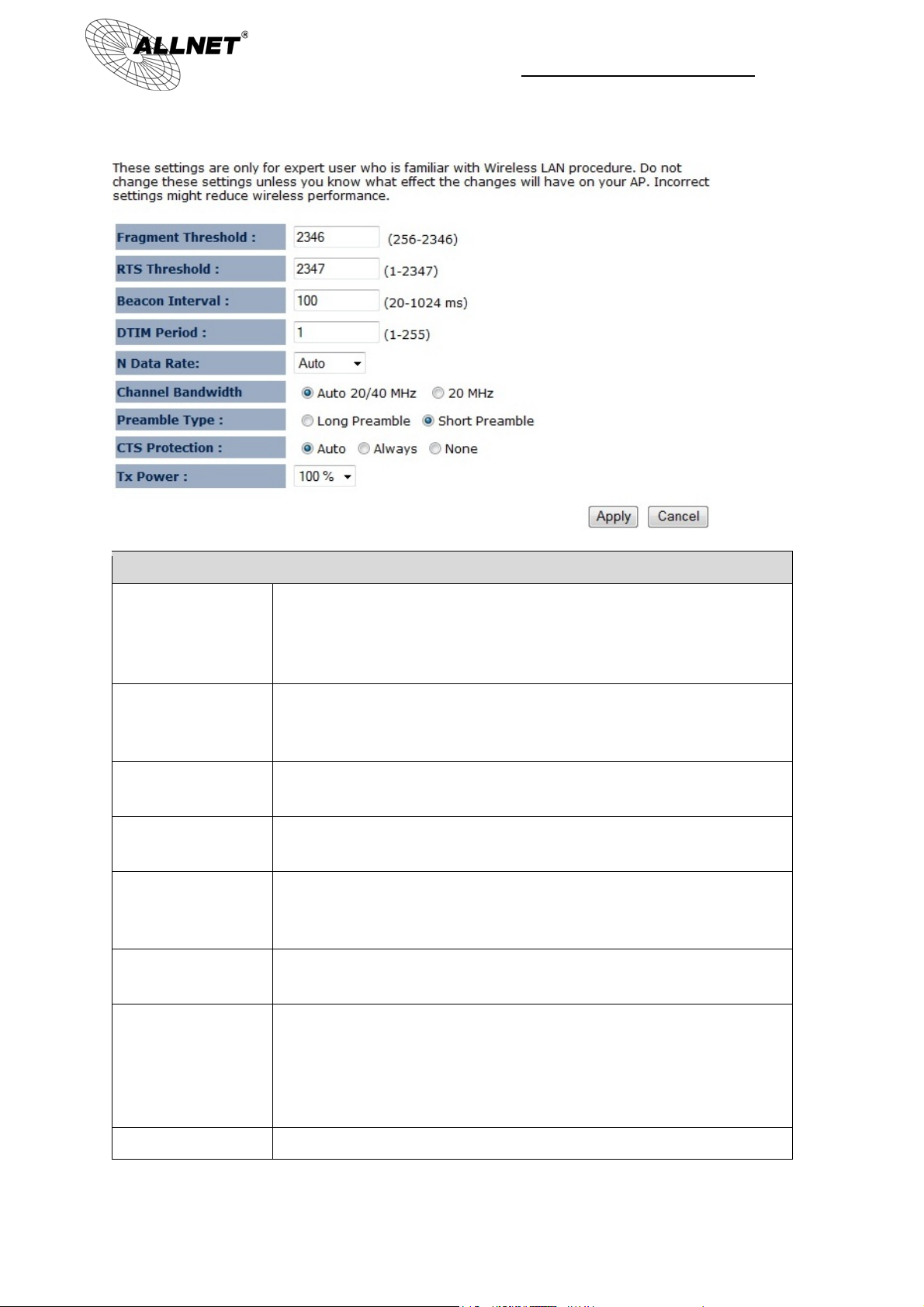
Access Point / WDS AP / Router / Repeater mode:
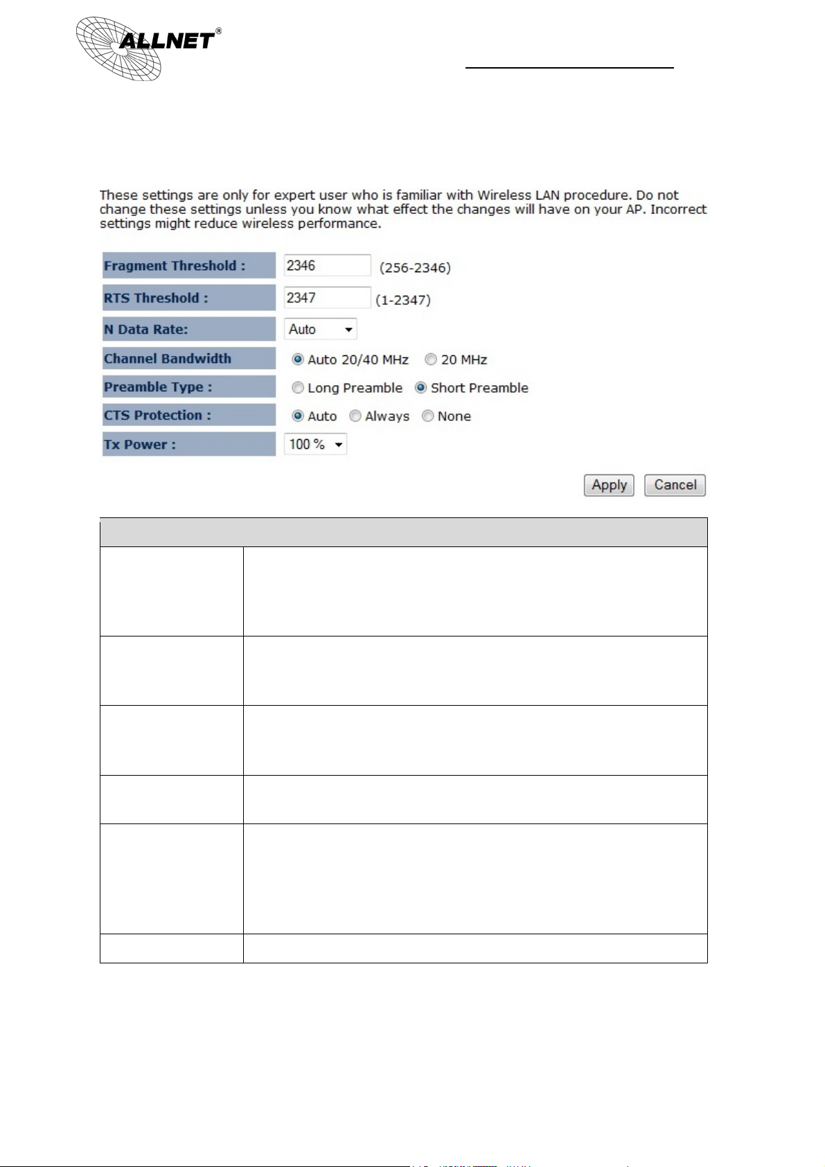
Advanced (Access Point / WDS AP / Router / Repeater mode)
Fragment
Threshold
RTS Threshold When the packet size is smaller than the RTS Threshold, the packet
Beacon Interval The time interval that the device broadcasts a beacon. This beacon
DTIM Period A Delivery Traffic Indication Message (DTIM) informs all wireless
N Data Rate You can limit the transfer rates between the device and wireless
Channel
Bandwidth
Specifies the maximum size of the packet per fragment. This
function can reduce the chance of packet collision.
However, when the fragment threshold is set too low, there will be
increased overhead resulting in poor performance.
will be sent without an RTS/CTS handshake, which may result in
incorrect transmission.
is used to synchronize all wireless clients on the network.
clients that the access point will be transmitting Multi-casted data.
clients. Each Modulation Coding Scheme (MCS) refers to a specific
transfer speed.
Set whether each channel uses 20Mhz or 40Mhz transmission
frequency. To achieve 11n speeds, 40Mhz channels must be used.
Preamble Type A preamble is a message that helps access points synchronize with
the client.
Long Preamble is standard based so increases compatibility.
Short Preamble is non-standard, resulting in decreased
compatibility, but increased performance.
Tx Po w er Set the power output of the wireless signal.
43
Page 45
WDS Bridge mode:
ALL02850N User’s Manual
Advanced (WDS Bridge mode)
Fragment
Threshold
RTS Threshold When the packet size is smaller than the RTS Threshold, the packet
N Data Rate You can limit the transfer rates between the device and wireless
Channel
Bandwidth
Preamble Type A preamble is a message that helps access points synchronize with
Specifies the maximum size of the packet per fragment. This
function can reduce the chance of packet collision.
However, when the fragment threshold is set too low, there will be
increased overhead resulting in poor performance.
will be sent without an RTS/CTS handshake, which may result in
incorrect transmission.
clients. Each Modulation Coding Scheme (MCS) refers to a specific
transfer speed.
Set whether each channel uses 20Mhz or 40Mhz transmission
frequency. To achieve 11n speeds, 40Mhz channels must be used.
the client.
Long Preamble is standard based so increases compatibility.
Short Preamble is non-standard, resulting in decreased
compatibility, but increased performance.
Tx Po w er Set the power output of the wireless signal.
44
Page 46
ALL02850N User’s Manual
6.5 Security
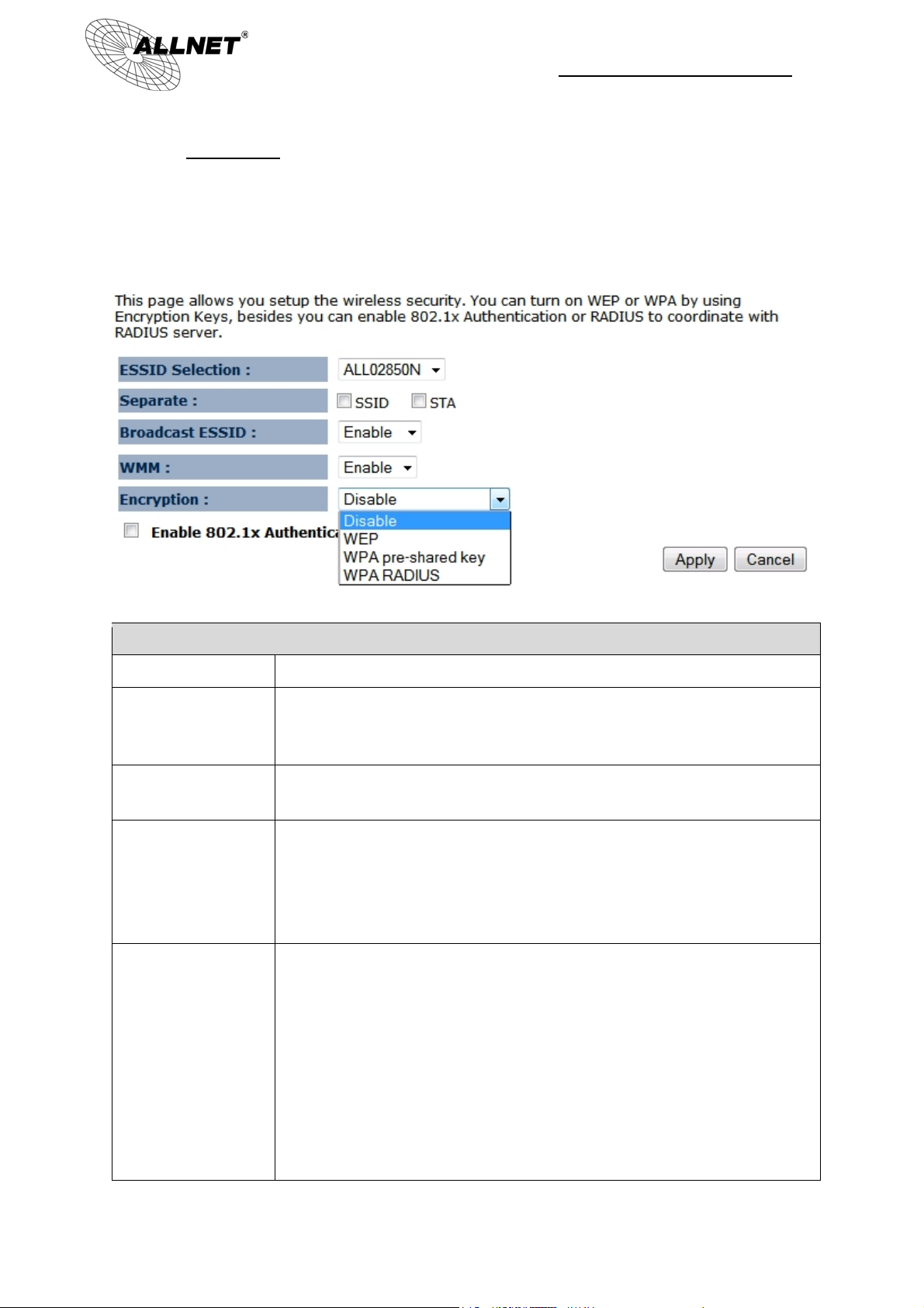
The Security option in the Wireless menu allows you to set the wireless security
settings.
Note: Only in Access Point / WDS AP / Router and Repeater mode.
Security (Access Point / WDS AP / Router / Repeater mode)
SSID Selection Select the SSID that the corresponding security settings will apply to.
Separate Separating the SSID from each other (or use of STA) prevents
communication and data sharing between wireless stations associated
with the SSIDs.
Broadcast SSID If Disabled, the ALL02850N will not broadcast the SSID. It will be
invisible to the clients.
WMM Wi-Fi Multi-Media is a Quality of Service protocol which prioritizes
traffic in the order according to voice, video, best effort, and
background.
Note: In certain situations, WMM needs to be enabled to achieve 11n
transfer speeds.
Encryption The encryption method to be used on the corresponding SSID.
You can choose between WEP, WPA Pre-Shared Key, or WPA RADIUS.
Disabled - No data encryption is used.
WEP - Data is encrypted using the WEP standard. WEP is the
Wired Equivalent Privacy security over a wireless network.
WPA-PSK - Data is encrypted using the WPA-PSK standard. This
is a later standard than WEP, and provides much better security
than WEP. WPA-PSK is Wi-Fi Protected Access using a
Pre-Shared Key. This is the equivalent of password protecting
your wireless network.
45
Page 47
ALL02850N User’s Manual
WPA2-PSK - This is a further development of WPA-PSK, and
offers even greater security, using the AES (Advanced Encryption
Standard) method of encryption.
WPA-RADIUS - This version of WPA requires a Radius Server on
your LAN to provide the client authentication according to the
802.1x standard. Data transmissions are encrypted using the WPA
standard.
If this option is selected:
This Access Point must have a Client Login on the Radius
Server.
Each user must have a User Login on the Radius Server.
Each user's wireless client must support 802.1x and provide
the login data when required.
All data transmission is encrypted using the WPA standard.
Keys are automatically generated, so no key input is required.
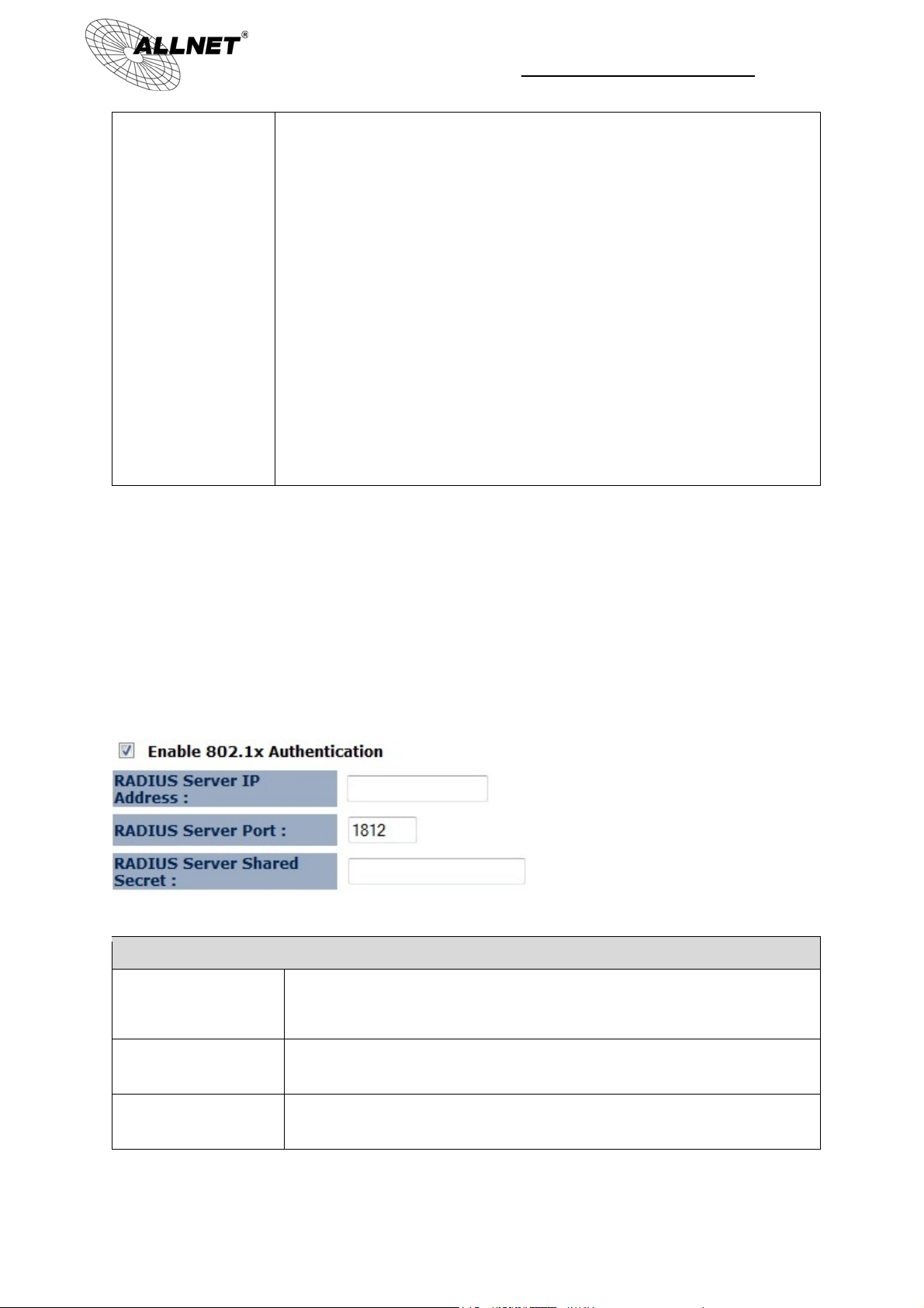
IEEE 802.1x is an authentication protocol. Every user must use a valid account to login to this
Access Point before accessing the wireless LAN. The authentication is then processed by a
RADIUS server. This mode only authenticates users by IEEE 802.1x, but it does not encrypt the
data during communication.
802.1x Authentication
RADIUS Server IP
The IP Address of the RADIUS Server.
Address
RADIUS Server
The port number of the RADIUS Server.
port
RADIUS Server
The RADIUS Server password.
password
46
Page 48
WEP Encryption:
ALL02850N User’s Manual
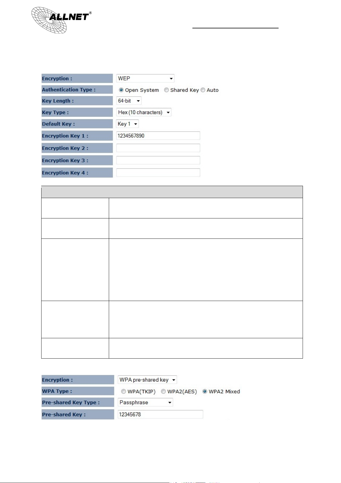
WEP Encryption
Authentication Type Please ensure that your wireless clients use the same authentication
type.
Key type ASCII: Using characters from the ASCII standard (recommended)
HEX: Uses hexadecimal characters.
Key Length The amount of bits the WEP key will use.
64 Bit - data is encrypted, using the default key, before being
transmitted. You must enter at least the default key. For 64 Bit
Encryption, the key size is 10 chars in HEX (0~9 and A~F).
128 Bit - data is encrypted, using the default key, before being
transmitted. You must enter at least the default key. For 128 Bit
Encryption, the key size is 26 chars in HEX (0~9 and A~F).
Default Key Select the key you wish to be the default. Transmitted data is
ALWAYS encrypted using the Default Key; the other Keys are for
decryption only.
You must enter a Key Value for the Default Key.
Encryption Key # Enter the key value or values you wish to use. Only the Key selected
as Default is required. The others are optional.
WPA Pre-Shared Key Encryption:
47
Page 49
ALL02850N User’s Manual
WPA Pre-Shared Key Encryption
WPA type Select the WPA encryption you would like.
Please ensure that your wireless clients use the same settings.
WPA(TKIP): Uses a Pre-Shared Key with a dynamically generated
key for each 128-bit packet.
WPA2(AES): Government standard of WPA2 encryption.
WPA2 Mixed: Allows the use of both WPA and WPA2 clients on
the network.
Pre-shared Key
Type
Pre-shared Key Wireless clients must use the same key to associate the device to the
Pre-Shared Key format (ASCII or Hexadecimal).
ALL02850N.
If using passphrase format, the Key must be from 8 to 63 characters in
length.
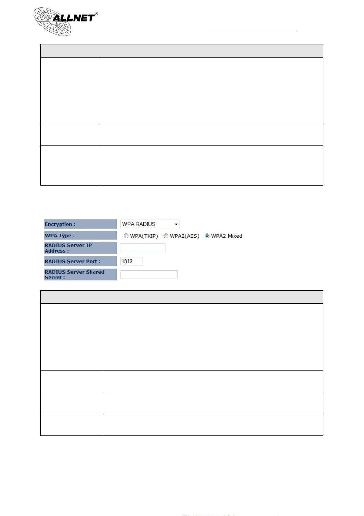
WPA RADIUS Encryption:
WPA RADIUS Encryption
WPA type Select the WPA encryption you would like.
Please ensure that your wireless clients use the same settings.
WPA(TKIP): Uses a Pre-Shared Key with a dynamically
generated key for each 128-bit packet.
WPA2(AES): Government standard of WPA2 encryption.
WPA2 Mixed: Allows the use of both WPA and WPA2 clients on the
network.
RADIUS Server IP
address
RADIUS Server
Port
RADIUS Server
password
Enter the IP address of the RADIUS Server.
Enter the port number used for connections to the RADIUS server.
Enter the password required to connect to the RADIUS server.
48
Page 50
ALL02850N User’s Manual
6.6 Filter
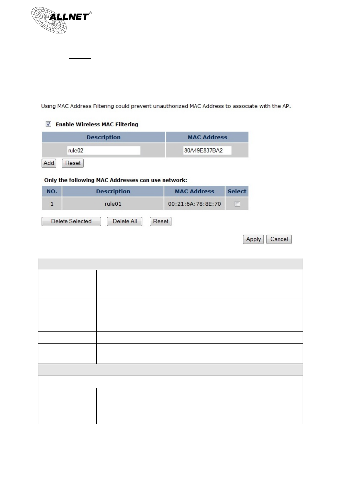
The Filter option in the Wireless menu allows users to allow clients with specific MAC
Addresses to join the SSID.
Note: Only in Access Point / WDS AP / Router and Repeater mode.
Wireless MAC Filter (Access Point / WDS AP / Router / Repeater mode)
Enable Wireless
Access Control
Description Enter a name or description for this entry.
MAC Address Enter the MAC address of the wireless client that you wish to allow
Add Click this button to add the entry.
Reset Click this button if you have made a mistake and want to reset the MAC
MAC Address Filtering Table
Only clients listed in this table will be allowed access to the wireless network.
Delete Selected Delete the selected entries.
Delete All Delete all entries.
Enable Wireless Access Control.
When Enabled, only wireless clients on the Filtering Table will be
allowed.
connection.
address and Description fields.
Reset Deselect all entries.
49
Page 51
ALL02850N User’s Manual
6.7 WPS (Wi-Fi Protected Setup)
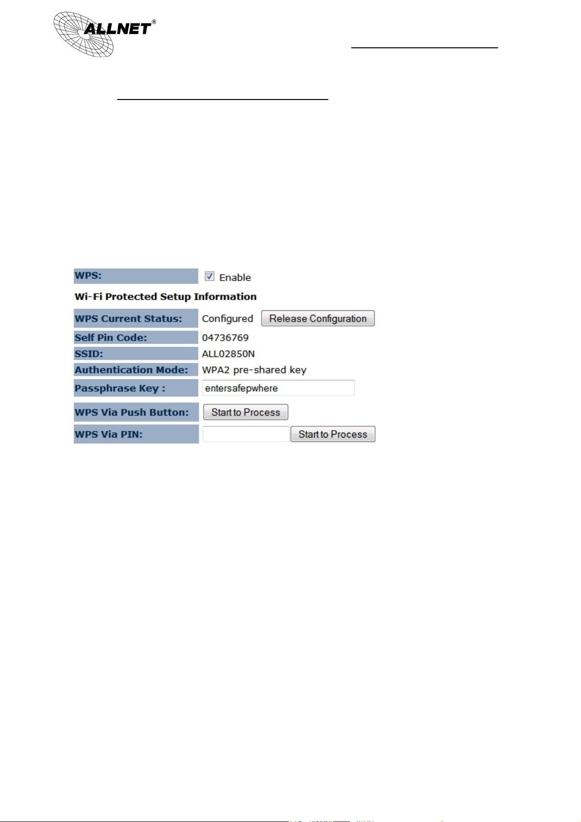
The WPS feature in the Wireless menu follows the Wi-Fi Alliance WPS standard. It
eases the set up of security-enabled Wi-Fi networks in homes and/or small office
environments.
It reduces the user steps required to configure a network and supports two
methods that are familiar to most consumers to configure a network and enable
security.
Note: Only in Access Point / WDS AP and Router mode.
50
Page 52
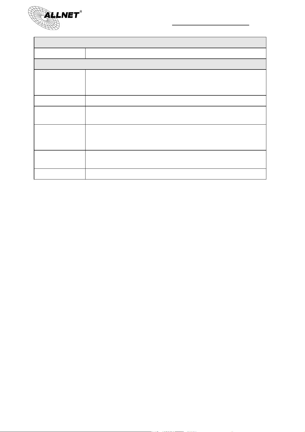
Wi-Fi Protected Setup (WPS)
WPS Check to Enable the WPS feature.
Wi-Fi Protected Setup Information
ALL02850N User’s Manual
WPS Current
Status
SSID The SSID (network name) used when connecting using WPS.
Authentication
Mode
Passphrase Key This is the passphrase key that is randomly generated during the WPS
WPS Via Push
Button
WPS Via PIN Activate WPS using the PIN code from the WPS device.
Shows whether the WPS function is Configured or Un-configured.
Configured means that WPS has been used to authorize connection
between the ALL02850N and the wireless clients.
Shows the encryption method used by the WPS process. This is set as
the mode selected in the Security option in the Wireless menu.
process. It is required if wireless clients that do not support WPS
attempts to connect to the wireless network.
Activate WPS using a push button.
51
Page 53
ALL02850N User’s Manual
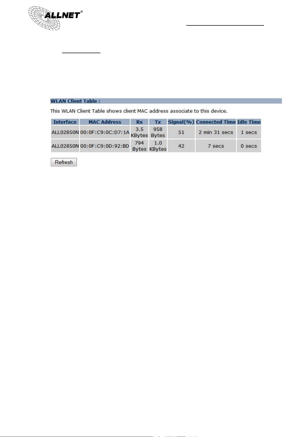
6.8 Client List
The Client List option of the Wireless menu shows all the wireless clients that are
currently connected to the ALL02850N.
Note: Only in Access Point / WDS AP / Router and Repeater mode.
52
Page 54
ALL02850N User’s Manual
6.9 VLAN
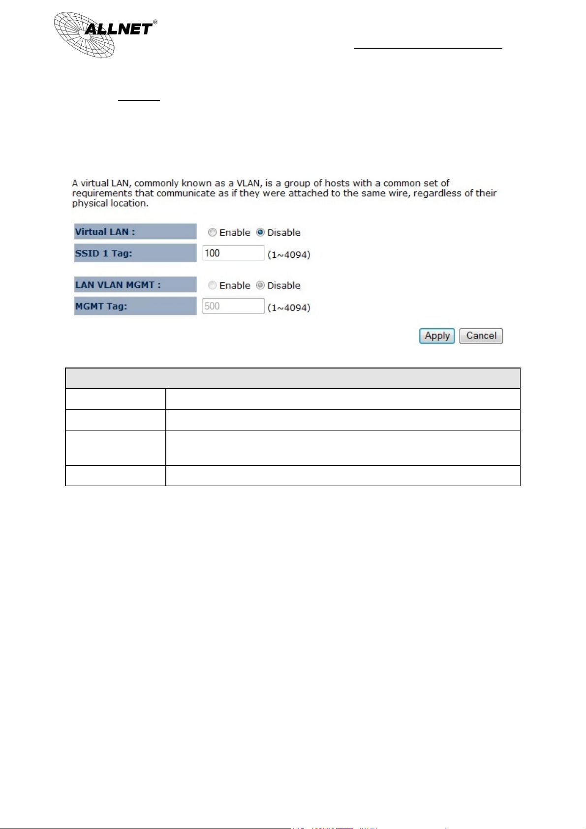
The VLAN option of the Wireless menu allows you to configure the VLAN (Virtual
LAN).
Note: Only in Access Point mode.
VLAN (Access Point and WDS AP mode)
Virtual LAN Choose to Enable or Disable the VLAN feature.
SSID# Tag Specify the VLAN tag for each SSID.
LAN VLAN
MGMT
MGMT Tag Specify the VLAN tag for the LAN.
Choose to Enable or Disable the LAN VLAN MGMT feature.
53
Page 55
ALL02850N User’s Manual
6.10 AP Profile
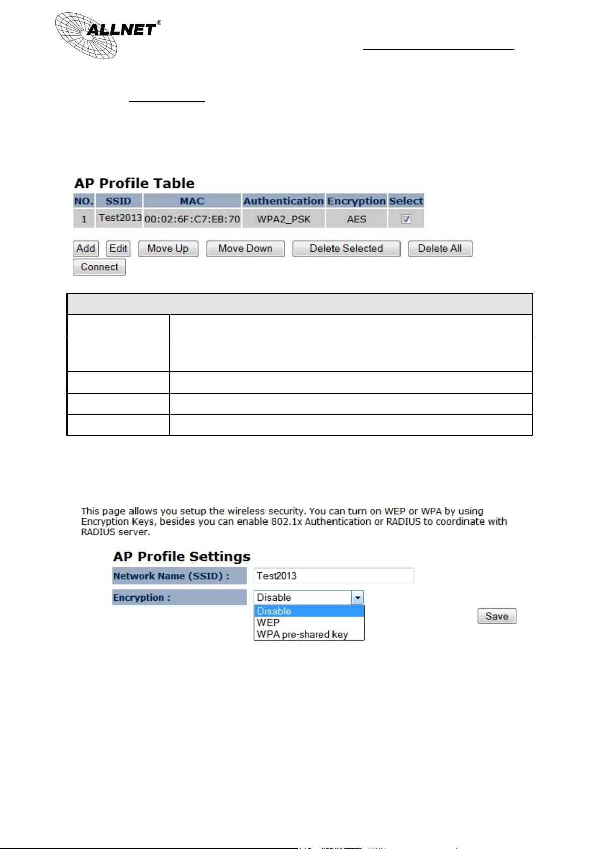
This page allows you to configure the profile of the Client Bridge including Security
Setting exactly the same as the Access Point. You can save three AP profiles at most.
Note: Only in Client Bridge mode.
AP Profile Table (Client Bridge mode)
Add / Edit Select a profile to add or edit.
Move Up / Move
Down
Delete Selected Delete the selected entries.
Delete All Delete all entries
Connect Select a profile to connect.
Select a profile to move up or move down.
54
Page 56

AP Profile Settings
ALL02850N User’s Manual
Network Name
(SSID)
Encryption The encryption method to be applied.
Enter the SSID (Network Name) of the wireless network which
ALL02850N want to connect.
You can choose from Disable, WEP, WPA pre-shared key and
RADIUS.
Please select the correct security type.
55
Page 57
ALL02850N User’s Manual
7 Network
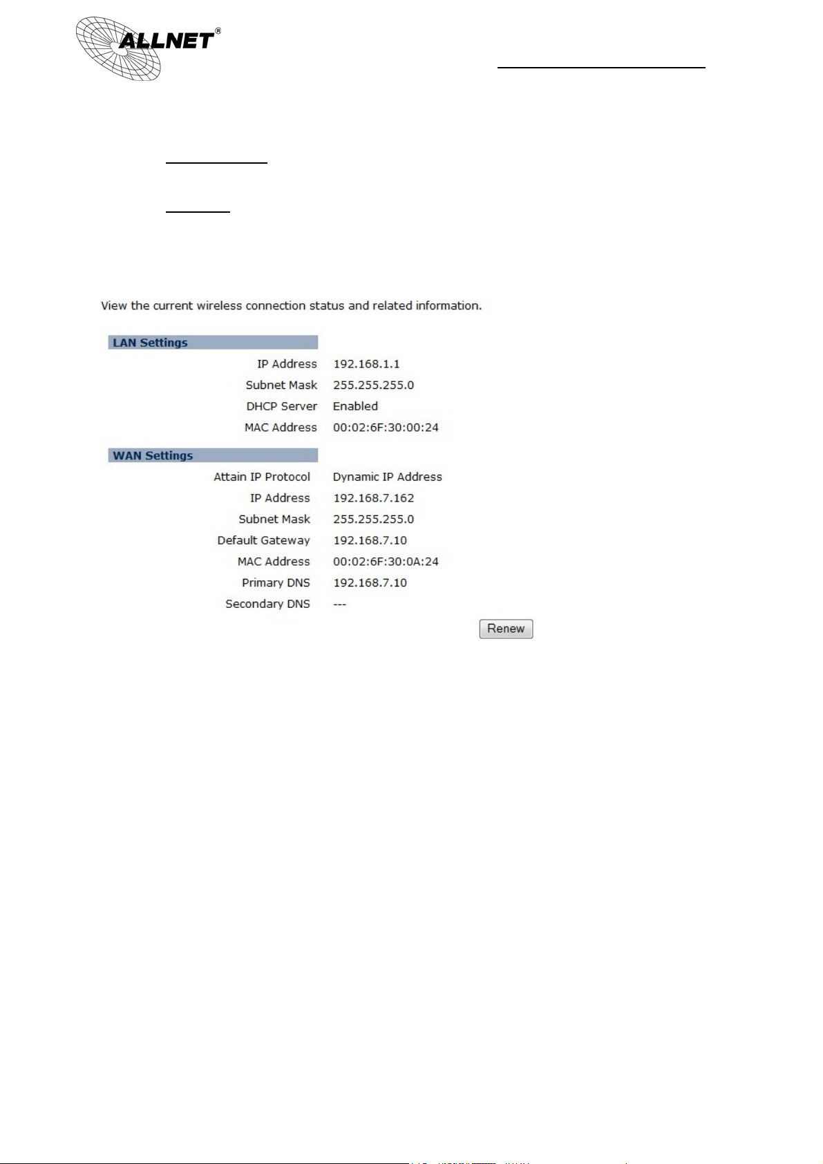
7.1 Status
The Status option of the Network menu shows the current status of the ALL02850N’s
LAN and WAN (Router mode) connection.
56
Page 58
ALL02850N User’s Manual
7.2 LAN
The LAN option of the Network menu allows you to modify the device's LAN
settings.
The LAN setting in Router mode:
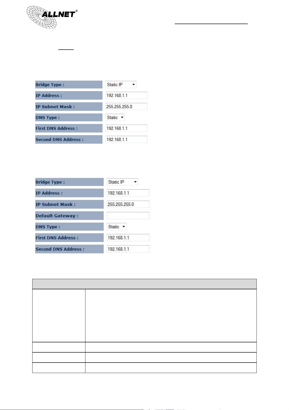
There is additional setting Default Gateway in Access Point / Client Bridge / WDS AP
/ WDS Bridge and Repeater mode.
LAN IP
Bridge Type Select the Bridge type of the LAN.
Static IP: Manually specify an IP address and subnet mask for the
ALL02850N to use.
Dynamic IP: The IP address is received automatically from the external
DHCP server.
Note: The option: Dynamic IP is only in Access Point and WDS AP
mode.
IP Address The LAN IP Address of this device.
IP Subnet Mask The LAN Subnet Mask of this device.
Default Gateway The Default Gateway of the device. Leave empty for default setting.
57
Page 59
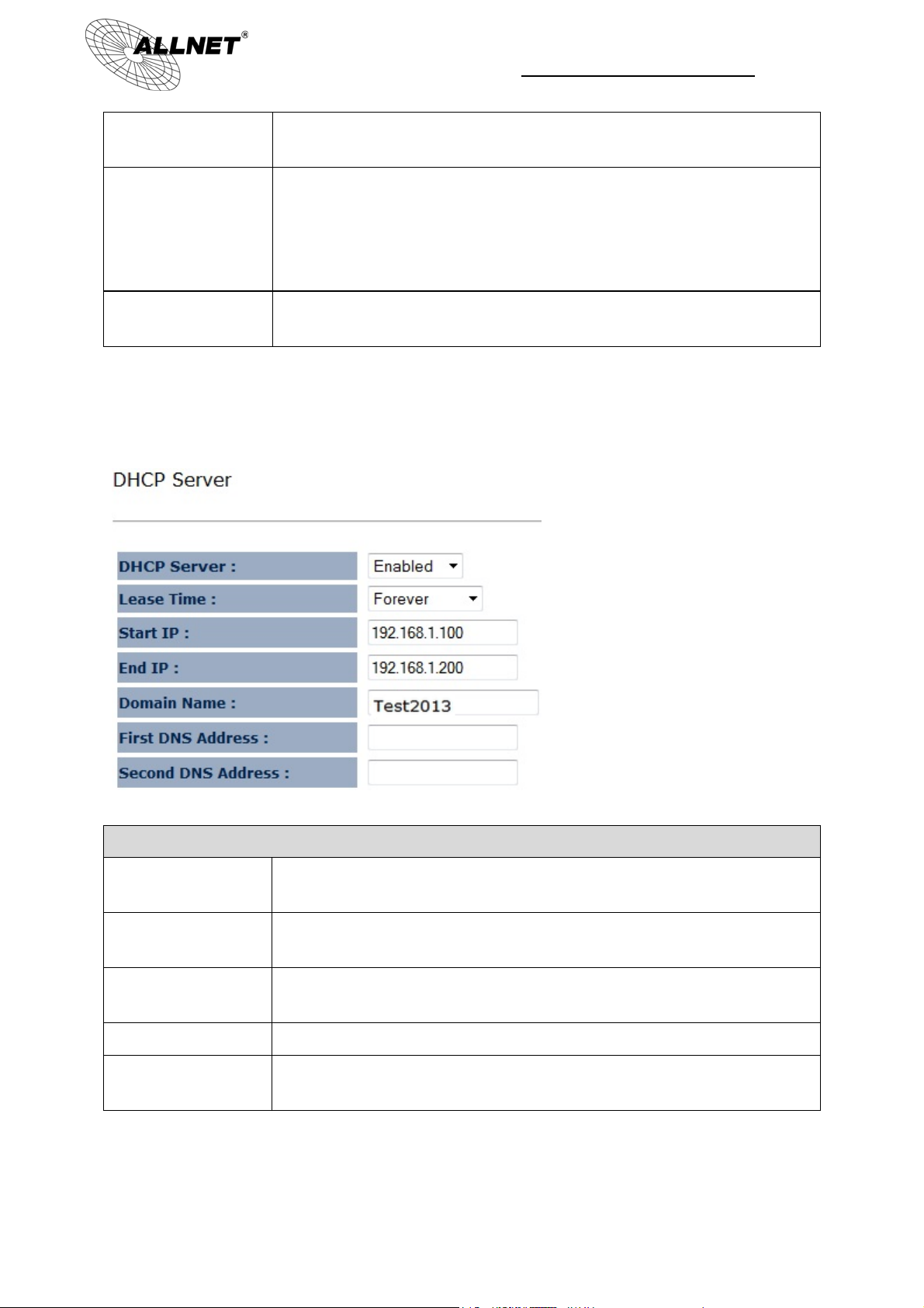
Note: The option: Dynamic IP is only in Access Point / Client Bridge /
WDS AP / WDS Bridge and Repeater mode.
DNS Type Select the DNS type of the LAN.
Static: Manually specify the DNS of the ALL02850N.
Dynamic: The DNS is received automatically from the external DNS
server.
Note: The option: Dynamic is only in Access Point and WDS AP mode.
ALL02850N User’s Manual
First / Second DNS
Address
The first / second DNS address for this device.
The DHCP Server feature is only available in Access Point and Router mode.
DHCP Server (Access Point / Router mode)
DHCP Server Enable or disable DHCP feature. The DHCP Server automatically
allocates IP addresses to your LAN device. Disabled as default.
Lease Time The duration of the DHCP server allocates each IP address to a LAN
device.
Start / End IP The range of IP addresses of the DHCP server will allocate to LAN
device.
Domain name The domain name for this LAN network.
First / Second DNS
Address
The first / second DNS address for this LAN network.
58
Page 60
ALL02850N User’s Manual
7.3 Spanning Tree
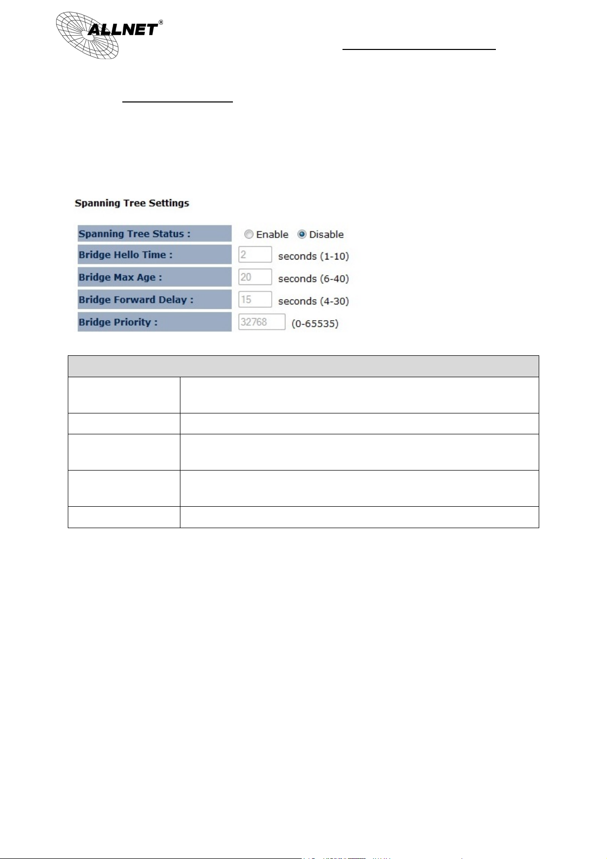
The Spanning Tree option of the Network menu allows you to set the ALL02850N to
use the Spanning Tree Protocol. Enabling Spanning Tree Protocol will prevent network
loops in your LAN network.
Note: Only in Access Point / Client Bridge / WDS AP / WDS Bridge and Repeater mode.
Spanning Tree Settings
Spanning Tree
Status
Bridge Hello Time The duration of the initial connection between two access points.
Bridge Max Age The maximum amount of time the bridge is connected when
Enable or disable the Spanning Tree Protocol.
transmitting.
Bridge Forward
Delay
Bridge Priority The priority port of the Spanning Tree Protocol.
The delay between transmissions between access points.
59
Page 61
ALL02850N User’s Manual
7.4 WAN (Router mode)
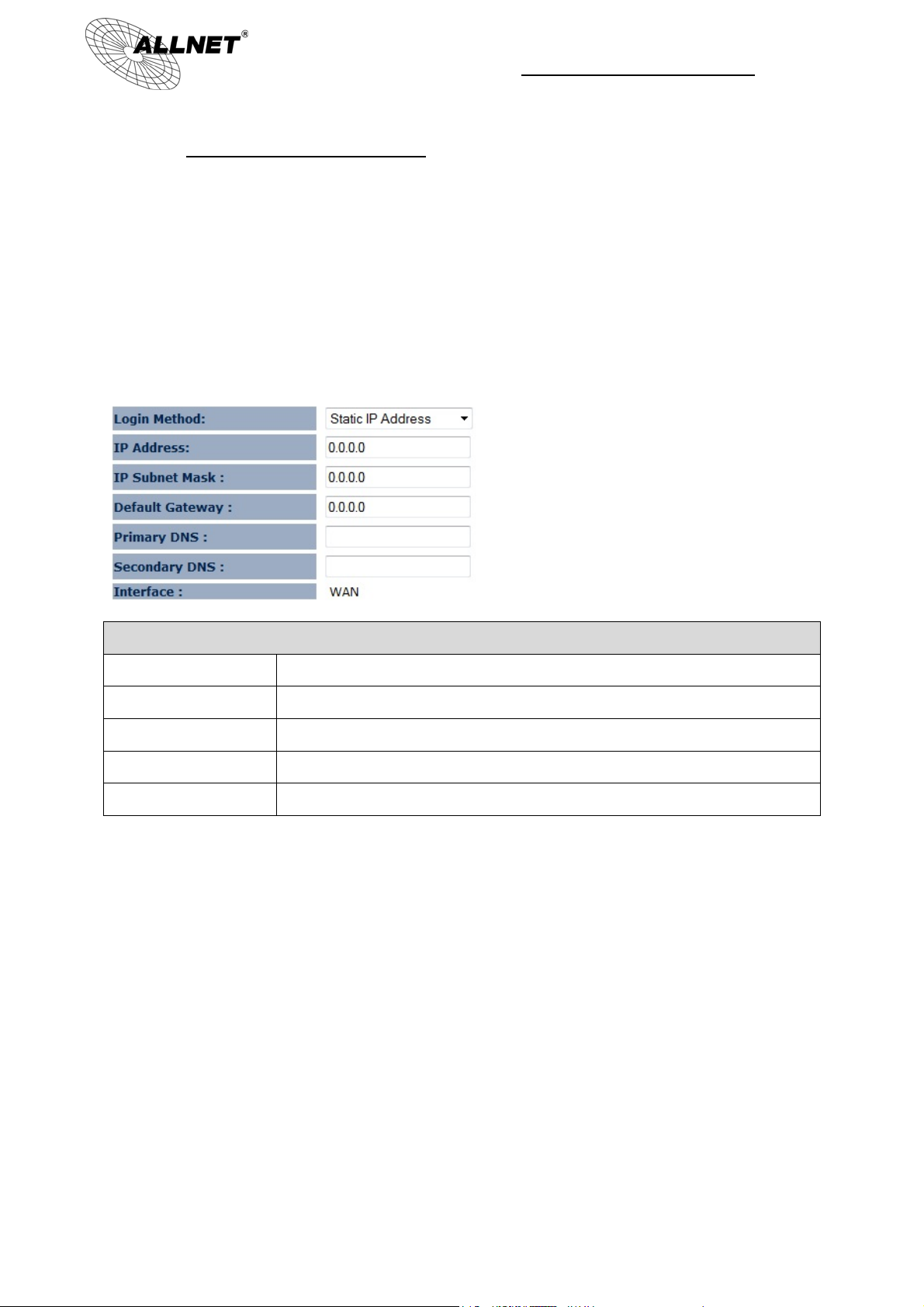
The WAN section allows you to manually set the WAN type connection and its related
settings.
Note: Only in Router mode.
7.4.1 Static IP Address
If your ISP Provider has assigned you a fixed IP address, enter the assigned IP address,
Subnet mask, Default Gateway IP address, and Primary DNS and Secondary DNS (if
available) of your ISP provider.
Static IP Address
IP Address Assign an IP address Manually.
IP Subnet Mask Specify an IP address’s subnet mask.
Default Gateway Specify the gateway of your network.
Primary DNS Specify the primary DNS server’s IP address.
Secondary DNS Specify the second DNS server’s IP address.
60
Page 62
ALL02850N User’s Manual
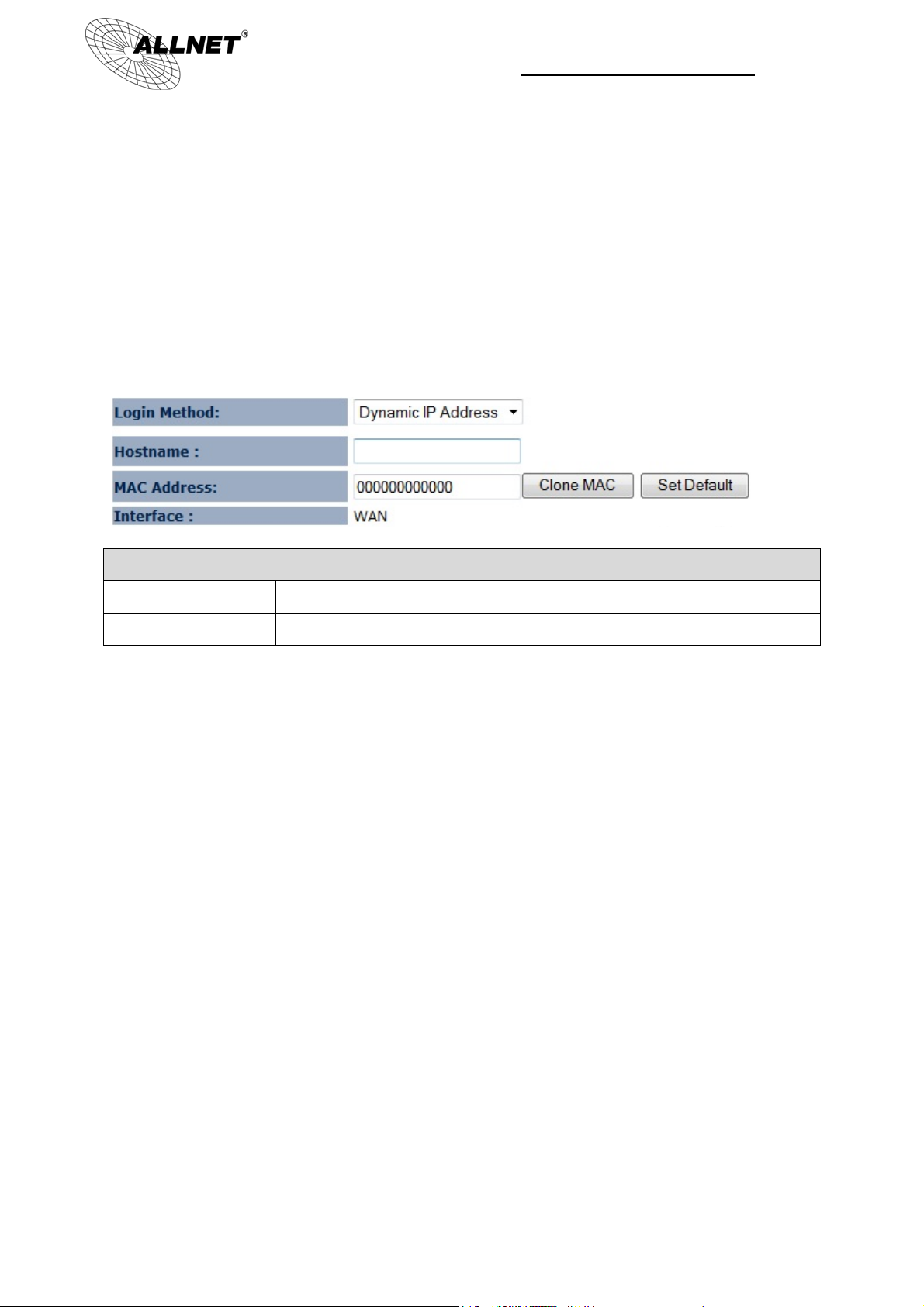
7.4.2 Dynamic IP Address
The IP Address is allocated automatically. However some ISP’s will also recognize the
MAC address and will reject connections if the MAC address does not match.
If your ISP has recorded the MAC address of your computer’s Ethernet LAN card,
please connect only the computer with the authorized MAC address, and click the
Clone MAC button.
Note: This will replace the WAN MAC address to the computer MAC address. The correct MAC address
is used to initiate the connection to the ISP.
Dynamic IP Address
Hostname This is optional. Only required if specified by ISP
MAC Address The MAC Address that is used to connect to the ISP.
61
Page 63
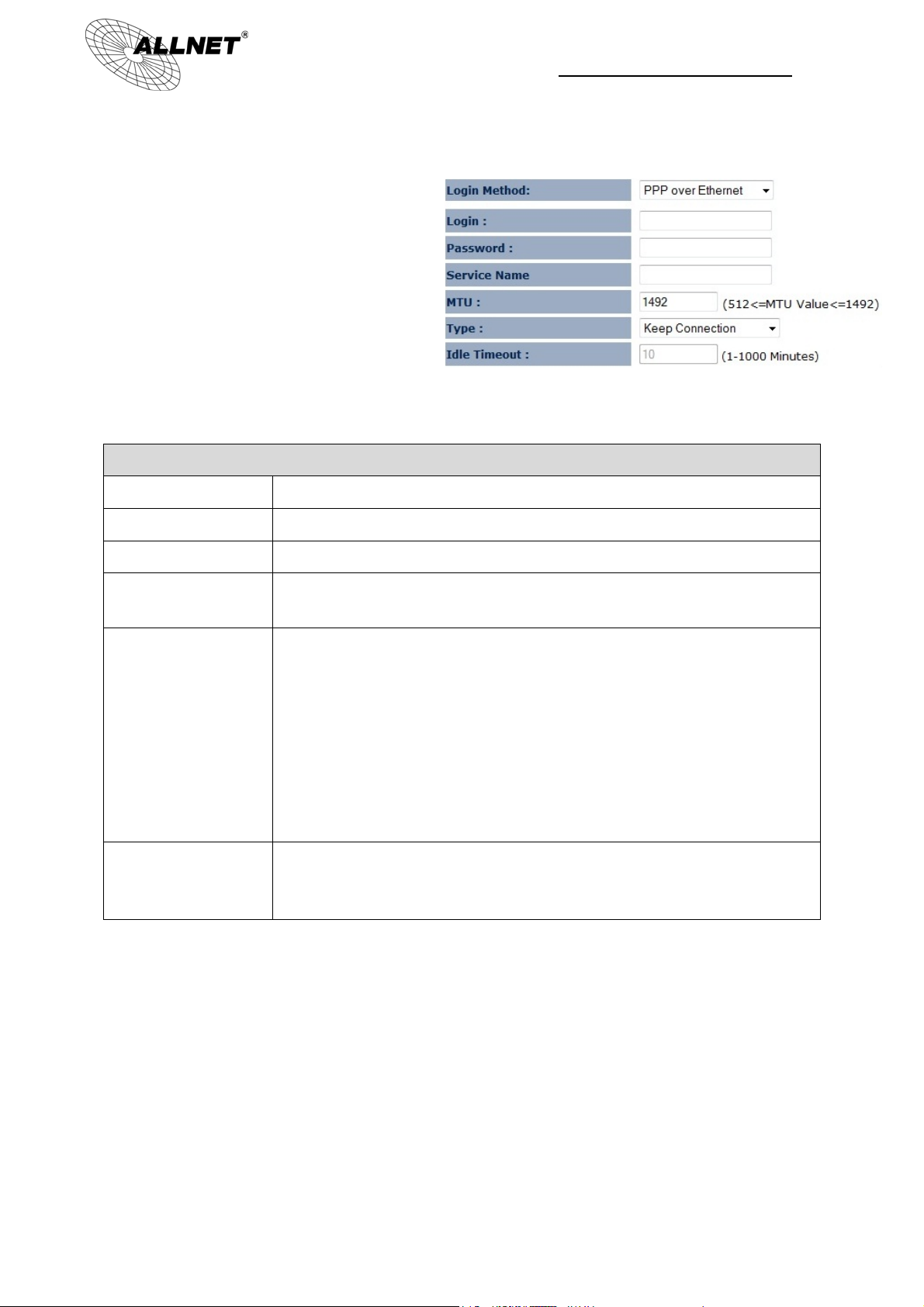
7.4.3 PPP over Ethernet (PPPoE)
This protocol is used by most DSL
services worldwide. Select this option
if you have a DSL connection.
Enter the username and password
provided by your ISP.
PPP over Ethernet (PPPoE)
Login Username assigned to you by the ISP
ALL02850N User’s Manual
Password Password for this username.
Service Name You can assign a name for this service. (Optional)
MTU The maximum size of packets.
Do not change unless mentioned by the ISP.
Type You can choose the method that the router maintains connection with
the ISP.
Keep Connection: The device will maintain a constant connection with
the ISP.
Automatic Connection: The device will only initiate connection to the
ISP when there is an Internet connection request made from a LAN
device.
Manual Connection: The user will need to manually connect to the
ISP by clicking the Connect button.
Idle Timeout: When the connection type is Automatic Connection, when Internet
traffic is idle, then the device will automatically disconnect from the ISP.
Please specify the Idle time in minutes.
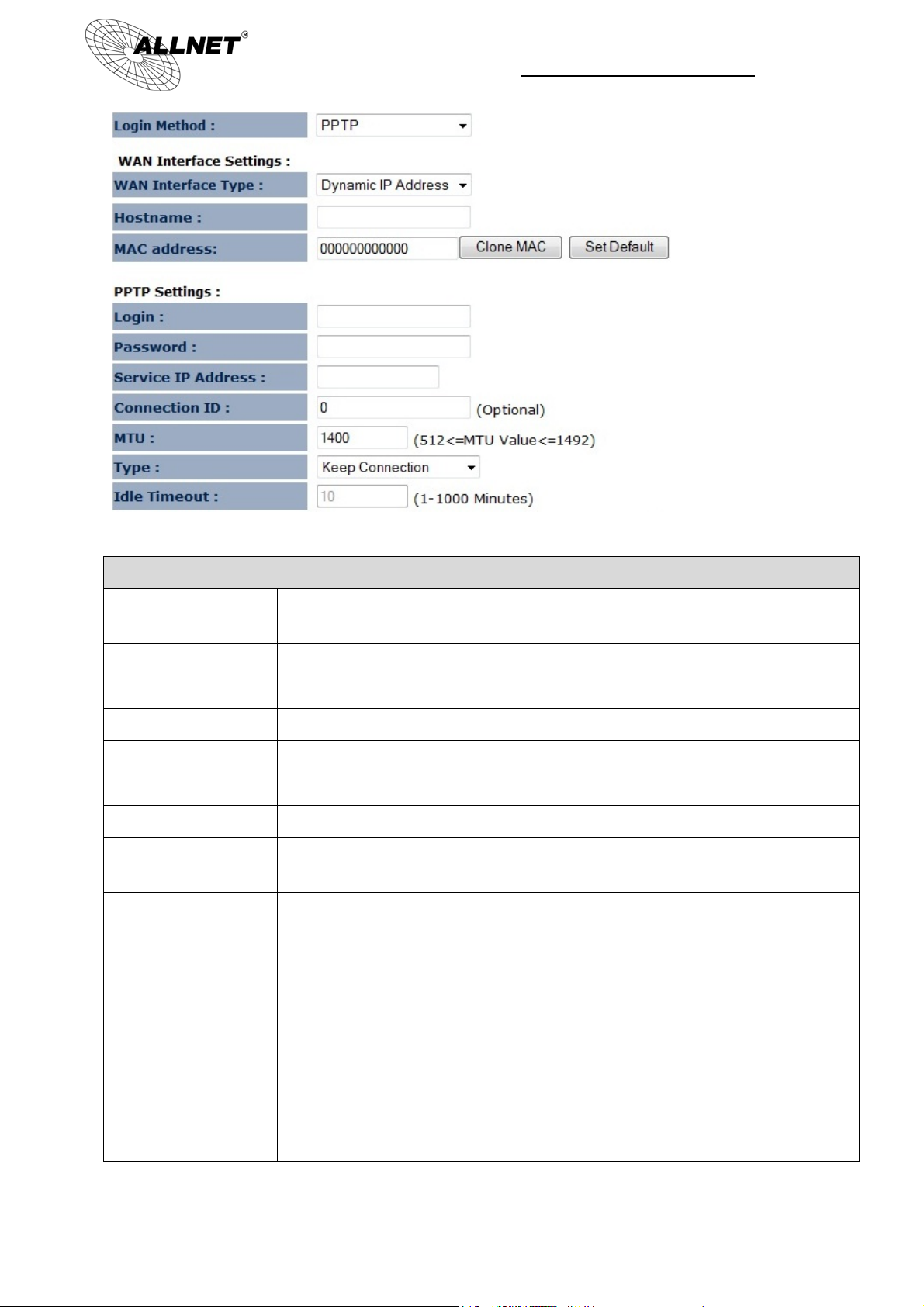
7.4.4 Point-to-Point Tunneling Protocol (PPTP)
PPTP is used by very few ISPs.
62
Page 64
ALL02850N User’s Manual
Point-to-Point Tunneling Protocol (PPTP)
WAN Interface
Type
Hostname This is optional. Only required if specified by ISP
MAC address The MAC Address that is used to connect to the ISP.
Login Username assigned to you by the ISP
Password Password for this username.
Service IP Address The IP Address of the PPTP server.
Connection ID This is optional. Only required if specified by ISP
MTU The maximum size of packets.
Type You can choose the method that the router maintains connection with the
Select whether the ISP is set to Static IP or will allocate Dynamic IP address.
Do not change unless mentioned by the ISP.
ISP.
Keep Connection: The device will maintain a constant connection with the
ISP.
Automatic Connection: The device will only initiate connection to the ISP
when there is an Internet connection request made from a LAN device.
Manual Connection: The user will need to manually connect to the ISP by
clicking the Connect button.
Idle Timeout: When the connection type is Automatic Connection, when Internet traffic
is idle, then the device will automatically disconnect from the ISP.
Please specify the Idle time in minutes.
63
Page 65
ALL02850N User’s Manual
8 Firewall
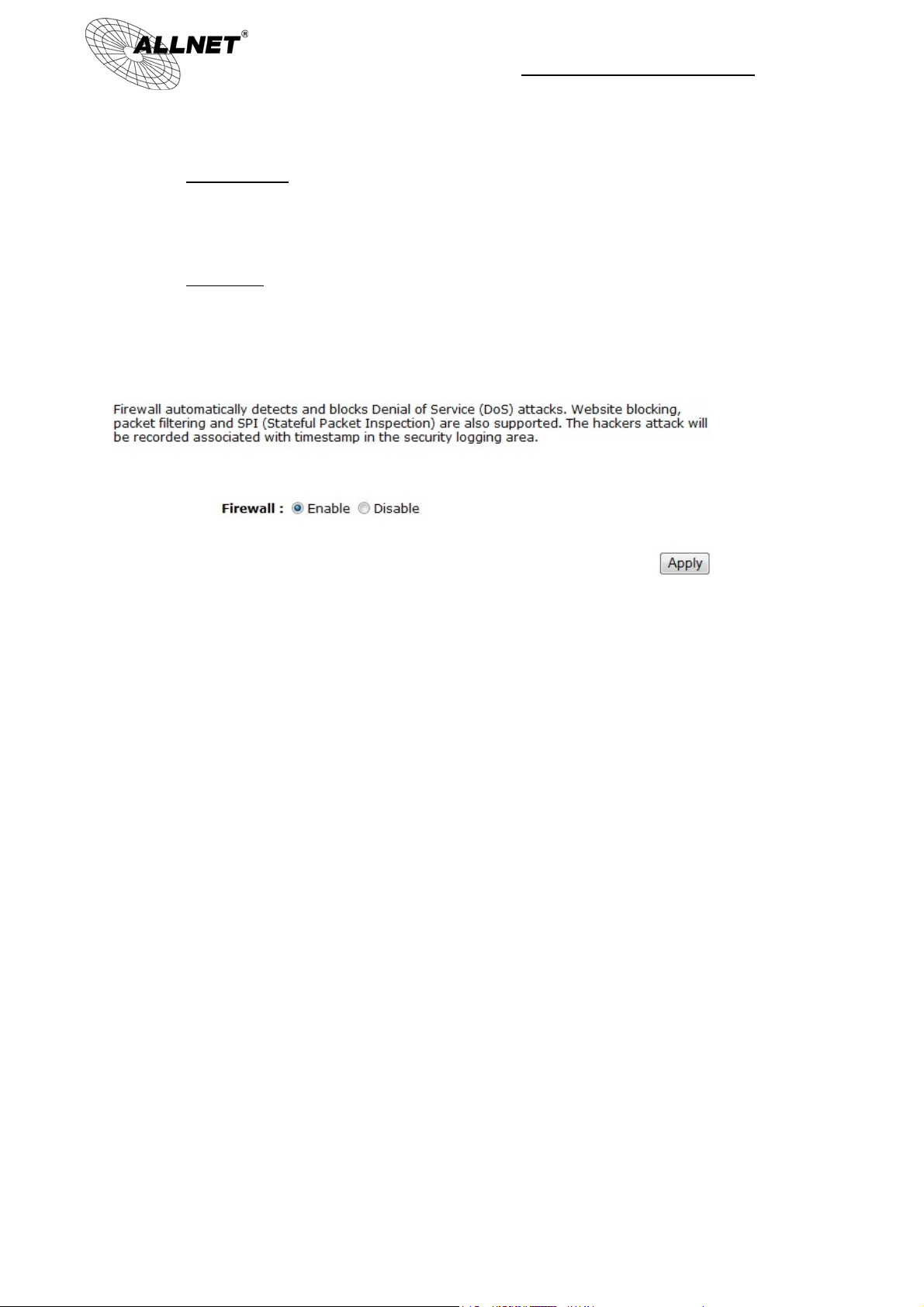
The Firewall section allows you to set the access control and Firewall settings.
Note: Only in Router mode.
8.1 Enable
This page allows you to Enable / Disable the Firewall features.
If enabled Firewall service, the Denial of Service (DoS) and SPI (Stateful Packet
Inspection) features will also be enabled.
64
Page 66
ALL02850N User’s Manual
8.2 DMZ
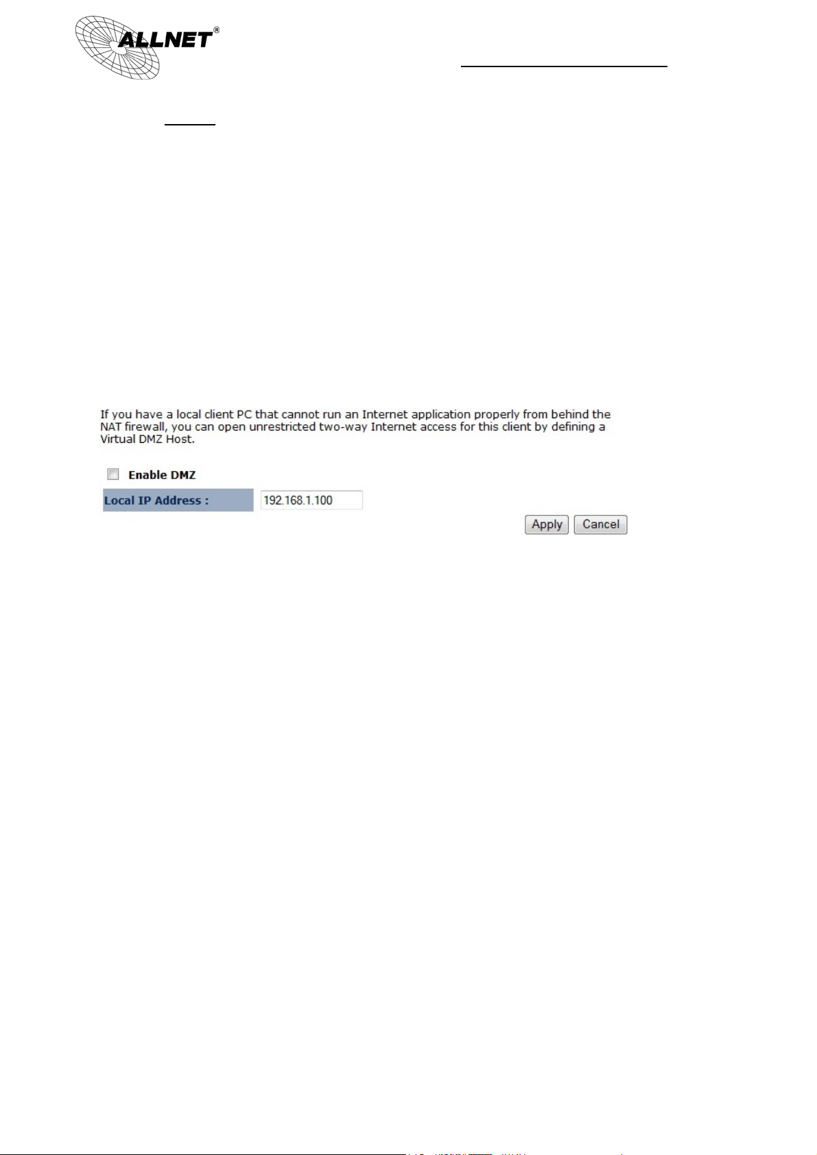
If enabled this feature, allows the DMZ computer on your LAN to be exposed to all
users on the Internet.
This allows almost any application to be used on the server.
The “DMZ PC” will receive all Unknown connections and data.
If the DMZ feature is enabled, please enter the IP address of
the PC to be used as the “DMZ PC”
Note: The “DMZ PC” is effectively outside the Firewall, making it more vulnerable to attacks. For this
reason, you should only enable the DMZ feature when required.
65
Page 67
ALL02850N User’s Manual
8.3 DoS
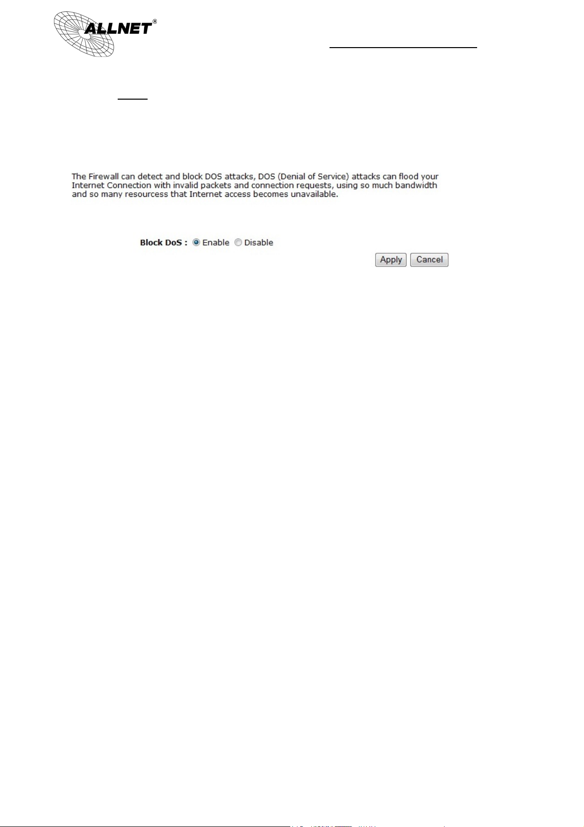
Denial of Service (Denial of Service) is a type of Internet attack that sends a high
amount of data to you with the intent to overload your Internet connection.
Enable the DoS firewall feature to automatically detect and block these DoS attacks.
66
Page 68
ALL02850N User’s Manual
8.4 MAC Filter
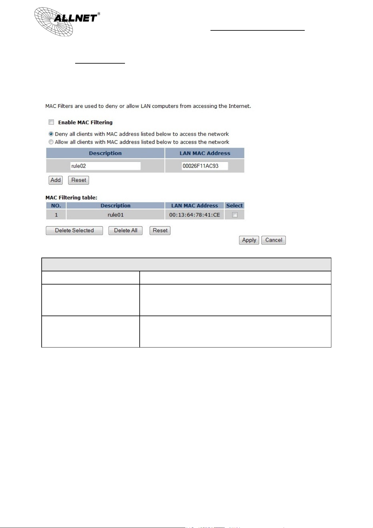
You can choose whether to Deny or only Allow those computers listed in the MAC
Filtering table to access the Internet.
MAC Filter
Enable MAC filtering Tick this box to Enable the MAC filtering feature.
Deny all clients with MAC
addresses listed below to
access the network
Allow all clients with MAC
addresses listed below to
access the network
When selected, the computers listed in the MAC Filtering
table will be Denied access to the Internet.
When selected, only the computers listed in the MAC
Filtering table will be Allowed access to the Internet.
67
Page 69
ALL02850N User’s Manual
8.5 IP Filter
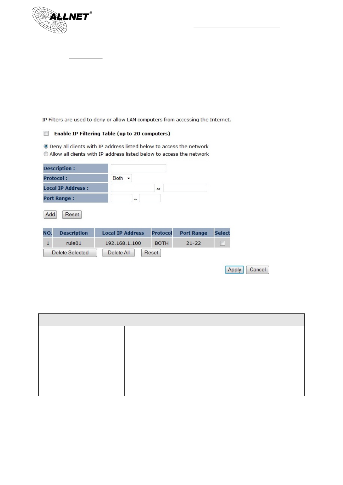
You can choose whether to Deny or only Allow, computer with those IP Addresses
from accessing certain Ports.
This can be used to control which Internet applications the computers can access.
You may need to have certain knowledge of what Internet ports the applications use.
IP Filter
Enable IP filtering Tick this box to Enable the IP filtering feature.
Deny all clients with IP
addresses listed below to
access the network
Allow all clients with IP
addresses listed below to
access the network
When selected, the computers with IP addresses specified will
be Denied access to the indicated Internet ports.
When selected, the computers with IP addresses specified will
be Allowed access only to the indicated Internet ports.
68
Page 70
ALL02850N User’s Manual
8.6 URL Filter
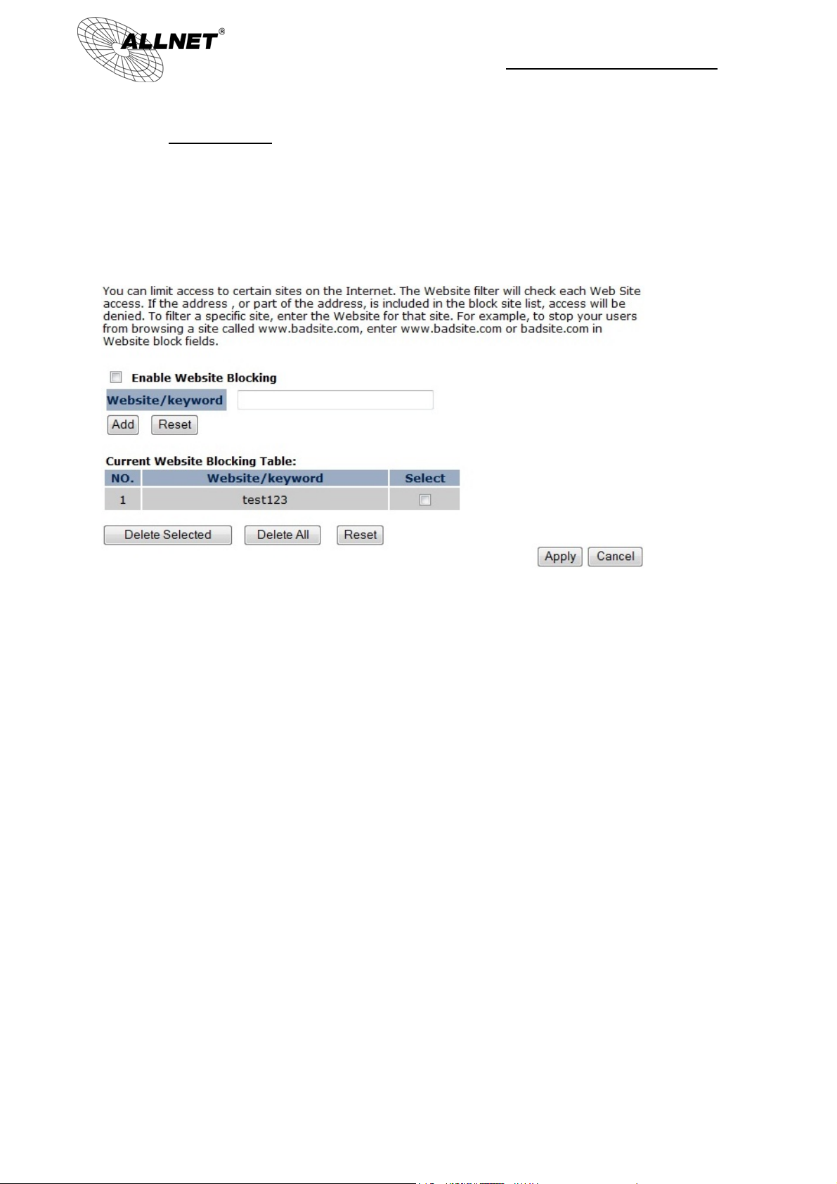
You can deny access to certain websites by blocking keywords in the URL web
address.
For example, “gamer” has been added to the URL Blocking Table. Any web address
that includes “gamer” will be blocked.
69
Page 71
ALL02850N User’s Manual
9 Advanced
The Advanced section allows you to configure the Advanced settings of the router.
Note: Only in Access Point Client Router mode.
9.1 Network Address Translation (NAT)
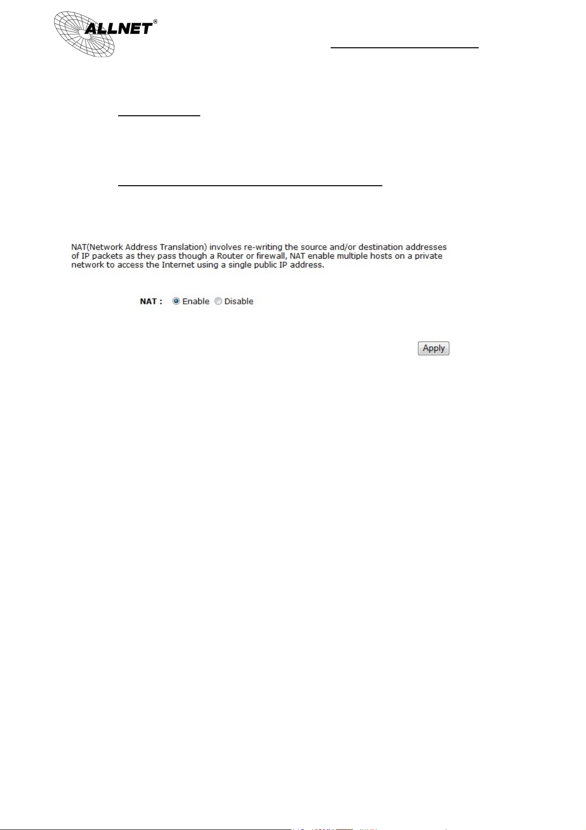
This page allows you to Enable / Disable the Network Address Translation (NAT)
feature. The NAT is required to share one Internet account with multiple LAN users.
70
Page 72
9.2 Port Mapping
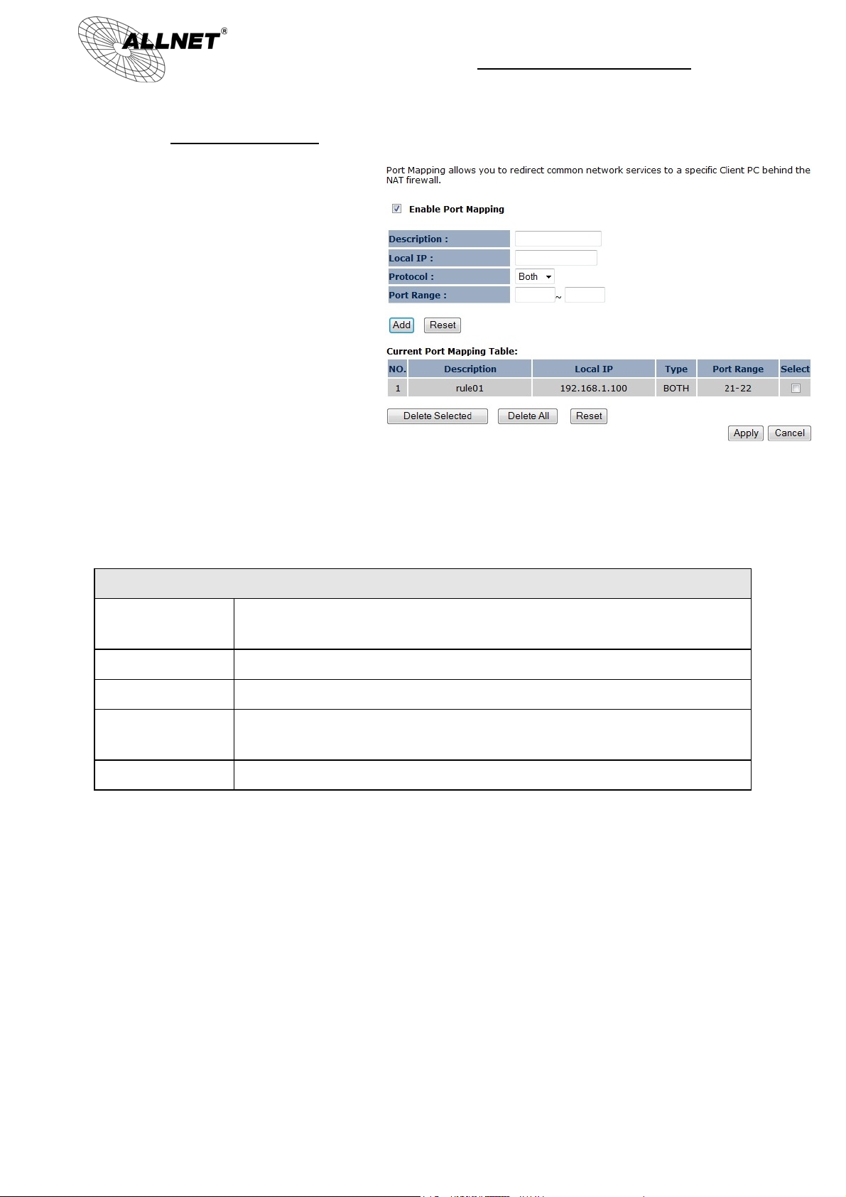
Port Mapping allows you to redirect
a particular range of ports to a
computer on your LAN network.
This helps you host servers behind
the NAT and Firewall.
In the example below, there is a FTP
Server that requires ports 21 to 22.
When there is a connection from
the Internet on those ports, it will
be redirected to the FTP Server at IP
address 192.168.1.100.
ALL02850N User’s Manual
Port Mapping
Enable Port
Mapping
Description Enter a name or description for this entry.
Local IP The local IP address of the computer the server is hosted on.
Protocol Select to apply the feature to TCP, UDP or Both types of packet
Port Range The range of ports that this feature will be applied to.
Check this box to enable the Port Mapping feature.
transmissions.
71
Page 73
9.3 Port Forwarding
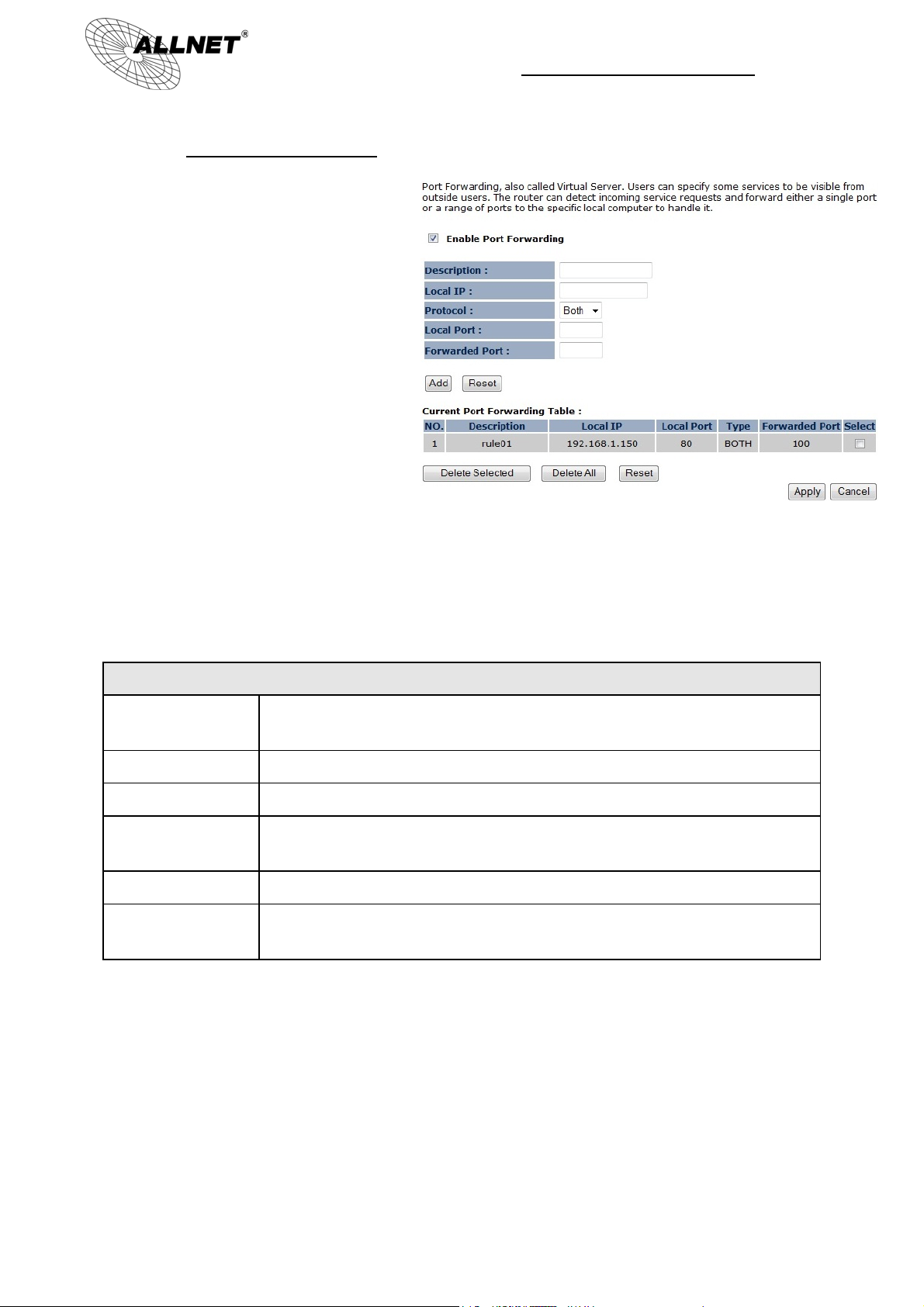
Port Forwarding allows you to
redirect a particular public port to a
computer on your LAN network.
This helps you host servers behind
the NAT and Firewall.
In the example below, there is a
Web Server running on port 80 on
the LAN.
For security reasons, the
Administrator would like to provide
this server to Internet connection
on port 100.
ALL02850N User’s Manual
Therefore when there is a connection from the Internet on port 100, it will be
forwarded to the computer with the IP address 192.168.1.150 and changed to port 80.
Port Forwarding
Enable Port
Forwarding
Description Enter a name or description for this entry.
Local IP The local IP address of the computer the server is hosted on.
Protocol Select to apply the feature to TCP, UDP or Both types of packet
Local Port The port that the server is running on the local computer.
Forwarded Port When a connection from the Internet is on this port, it will be forwarded
Check this box to enable the Port Forwarding feature.
transmissions.
to the indicated local IP address.
72
Page 74
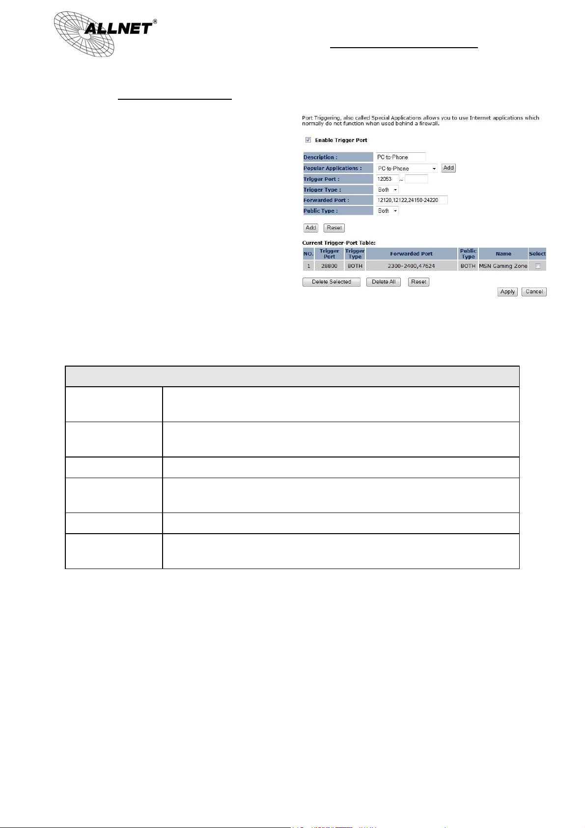
9.4 Port Triggering
If you use Internet applications which use
non-standard connections or port
numbers, you may find that they do not
function correctly because they are
blocked by the Wireless Router's firewall.
Port Triggering will be required for these
applications to work.
ALL02850N User’s Manual
Port Triggering
Enable Port
Triggering
Popular
Applications
Trigger Port This is the outgoing (outbound) port numbers for this application.
Trigger Type Select whether the application uses TCP, UDP or Both types of protocols
Forwarded Port These are the inbound (incoming) ports for this application.
Public Type Select whether the application uses TCP, UDP or Both types of protocols
Check this box to enable the Port Trigger feature.
This is a list of some common applications with preset settings.
Select the application and click Add to automatically enter the settings.
for outbound transmissions.
for inbound transmissions.
73
Page 75
ALL02850N User’s Manual
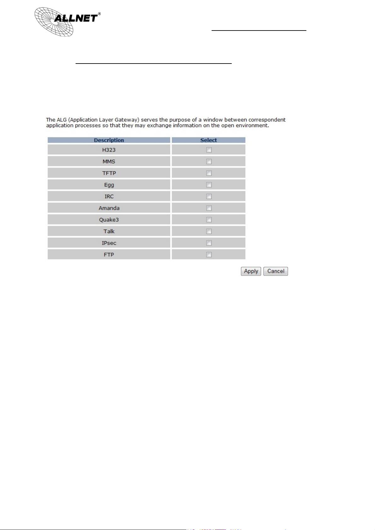
9.5 Application Layer Gateway (ALG)
Certain applications may require the use of the ALG feature to function correctly. If
you use any of the applications listed on the table below, select the feature and click
Apply.
74
Page 76
ALL02850N User’s Manual
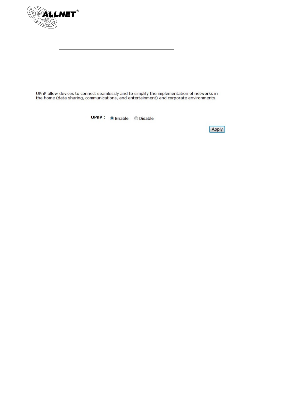
9.6 Universal Plug and Play (UPnP)
The UPnP function allows automatic discovery and configuration of UPnP enabled
devices on your network. It also provides automatic port forwarding for supported
applications to seamlessly bypass the Firewall.
75
Page 77
ALL02850N User’s Manual
9.7 Quality of Service (QoS)
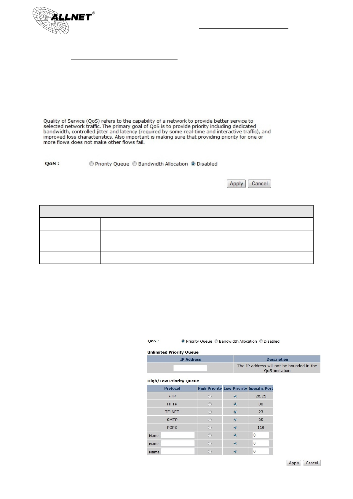
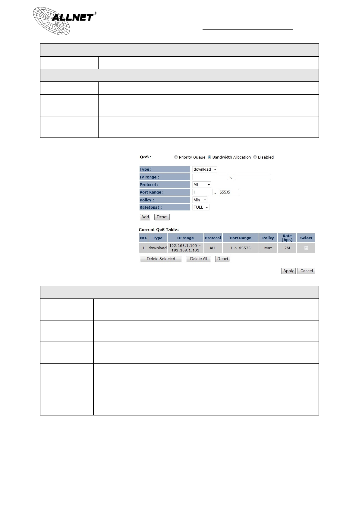
QoS allows you to control the priority that the data is transmitted over the Internet, or
to reserve a specific amount of Internet bandwidth. This is to ensure that applications
get enough Internet bandwidth for a good user experience.
QoS
Priority Queue Sets the QoS method to Priority Queue.
Bandwidth
Allocation
Disabled Disables the QoS feature.
Sets the QoS method to Bandwidth Allocation.
Priority Queue Method
Bandwidth priority is set to
either High or Low. The data
transmissions in the High
Priority queues will be
processed first.
76
Page 78
ALL02850N User’s Manual
Unlimited Priority Queue
IP Address The computer with this IP Address will not be bound by the QoS rules.
High / Low Priority Queue
Protocol The type of network protocol.
High / Low
Priority
Specific Port Each protocol uses a specific port range.
Sets the protocol to High or Low priority.
Please specify the ports used by this protocol.
Bandwidth Allocation
Method
You can set the maximum
amount of bandwidth a
certain protocol will use at
one time. Or you can set a
minimum amount of
bandwidth that will be
guaranteed to a certain
protocol.
Bandwidth Allocation
Type Set whether the QoS rules apply to transmission that are Download, Upload
or Both directions.
IP range Enter the IP address range of the computers that you would like the QoS
rules to apply to.
Protocol Select from this list of protocols to automatically set the related port
numbers.
Port Range Each protocol uses a specific port range. Specify the ports used by this
protocol.
Policy Choose whether this rule is to set a limit on the Maximum amount of
bandwidth allocated to the specified protocol, or to set the guaranteed
Minimum amount of bandwidth for the protocol.
77
Page 79
9.8 Static Routing
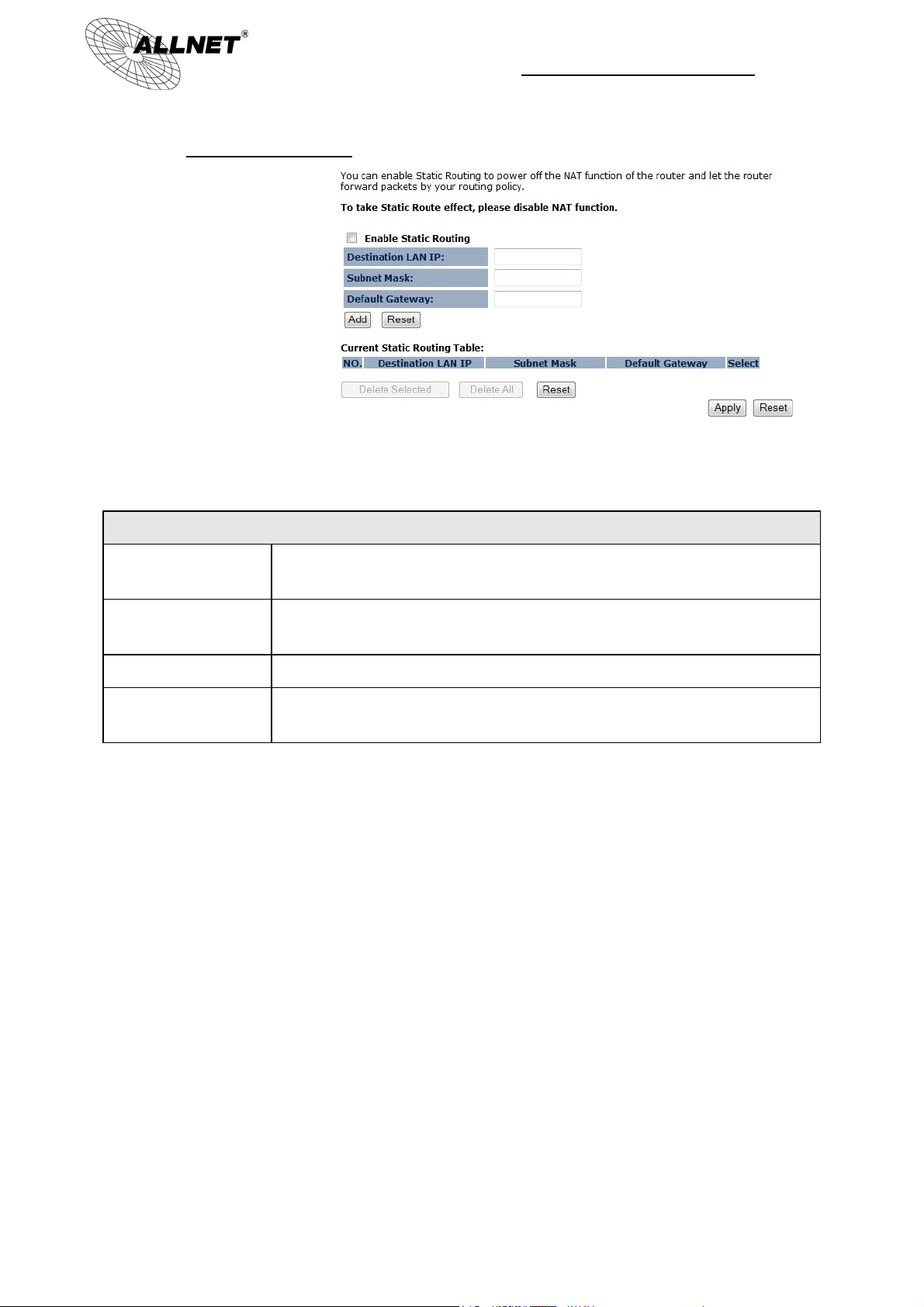
If your wireless router is
connected to a network
with different subnets,
this feature will allow the
different subnets to
communicate with each
other.
Note: The NAT function needs
to be disabled for the Routing
feature to be enabled.
ALL02850N User’s Manual
Static Routing
Enable Static
Routing
Destination LAN
IP
Subnet Mask Enter the Subnet Mask of the destination LAN IP address
Default Gateway Enter the IP address of the Default Gateway for this destination IP and
Check this box to enable the Static Router feature.
Enter the IP address of the destination LAN.
Subnet.
78
Page 80
ALL02850N User’s Manual
9.9 Dynamic Routing
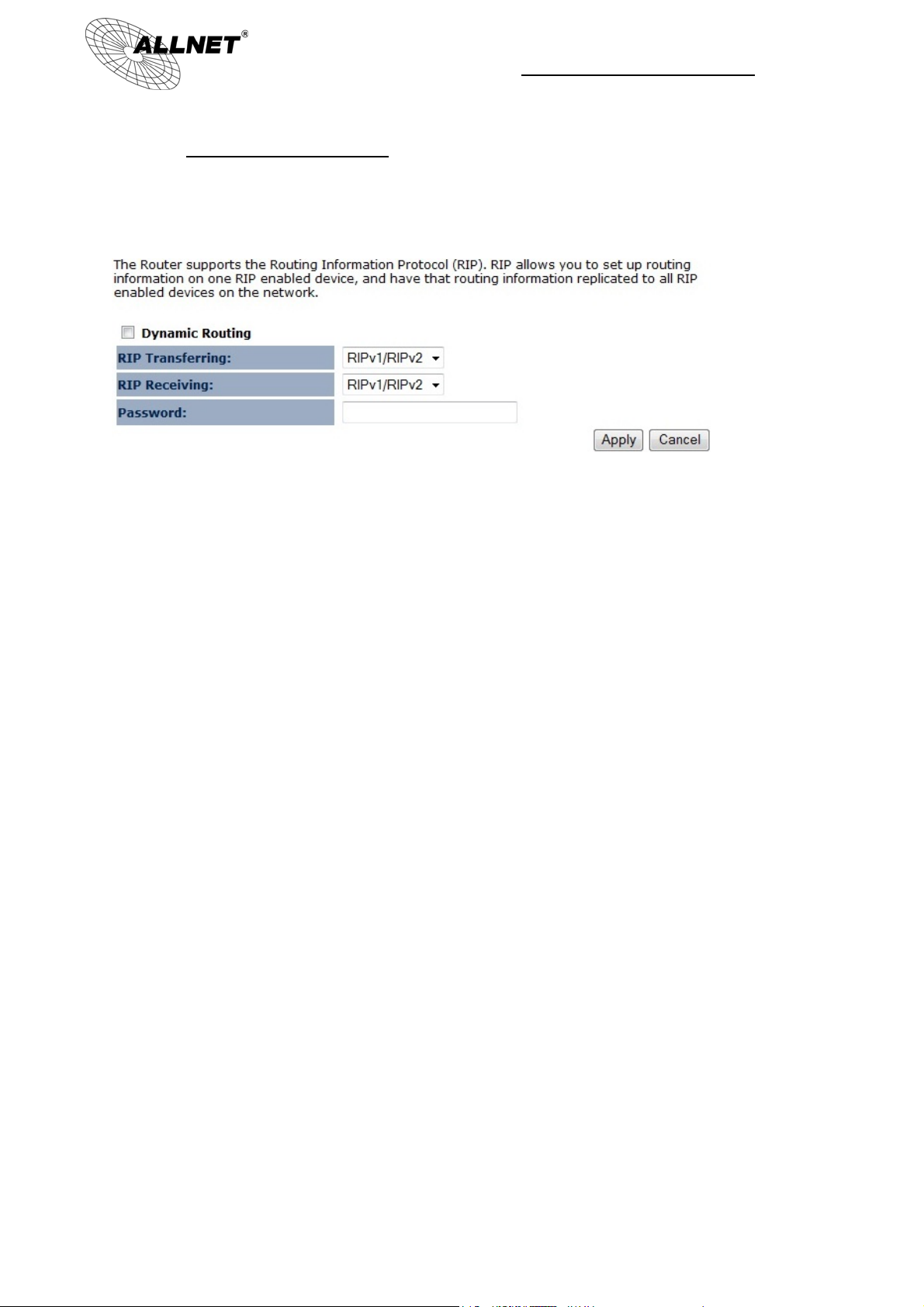
Dynamic routing allows routing tables in routers to change as the possible routes
change. This device use RIP to support dynamic routing.
79
Page 81
ALL02850N User’s Manual
9.10 Routing Table
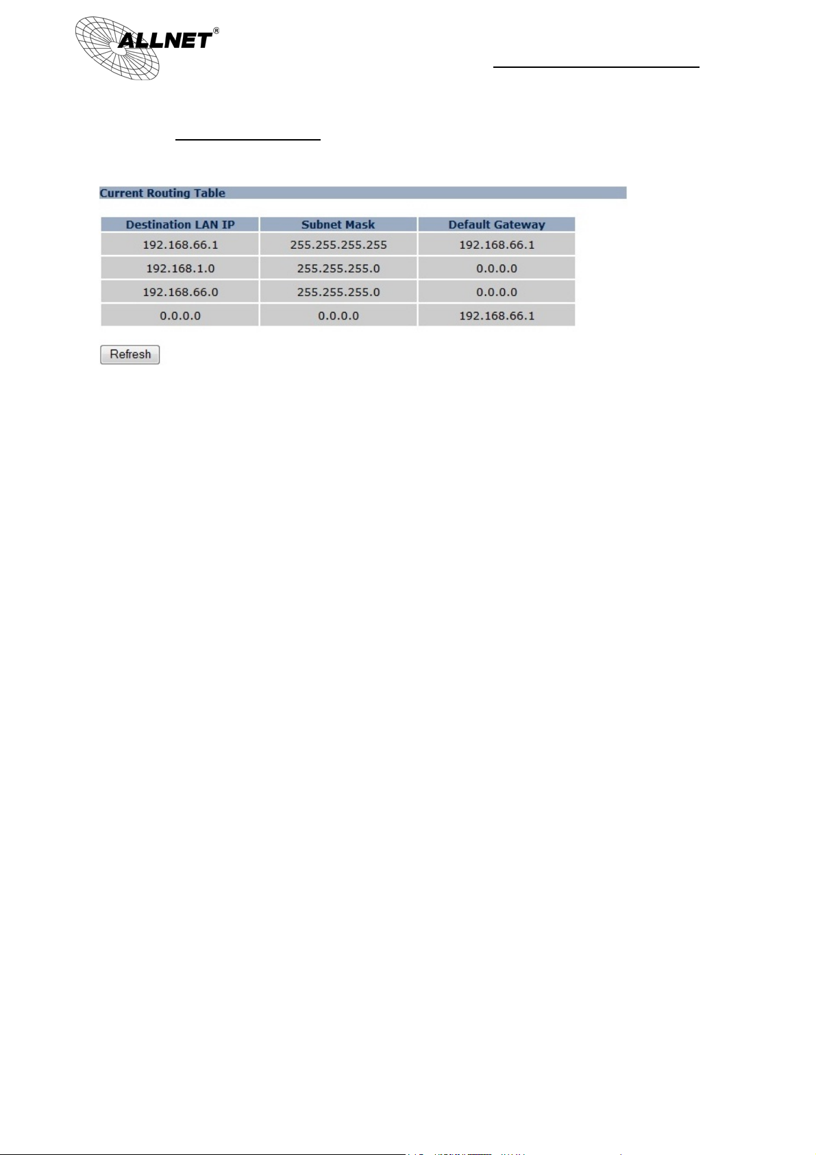
This page allows you to observe the current routing table.
80
Page 82

ALL02850N User’s Manual
10 Management
10.1 Admin
The Admin section of the Management menu allows you to change the ALL02850N
default password and to configure remote management (Router mode). By default,
the password is: admin. The password can contain 0 to 12 alphanumeric characters
and is case sensitive.
Change Password
Old Password Enter the current password.
New Password Enter your new password.
Confirm
Password
Idle Timeout Enter Administration Page timeout time (minutes).
Re-enter your new password.
There is additional setting Remote Management in Router mode.
Remote Management (Router mode)
Host Address You can only perform remote management from the specified IP
address. Leave blank to allow any host to perform remote management.
Port Enter the port number you want to accept remote management
connections.
Enable Tick to Enable the remote management feature.
81
Page 83
ALL02850N User’s Manual
10.2 SNMP
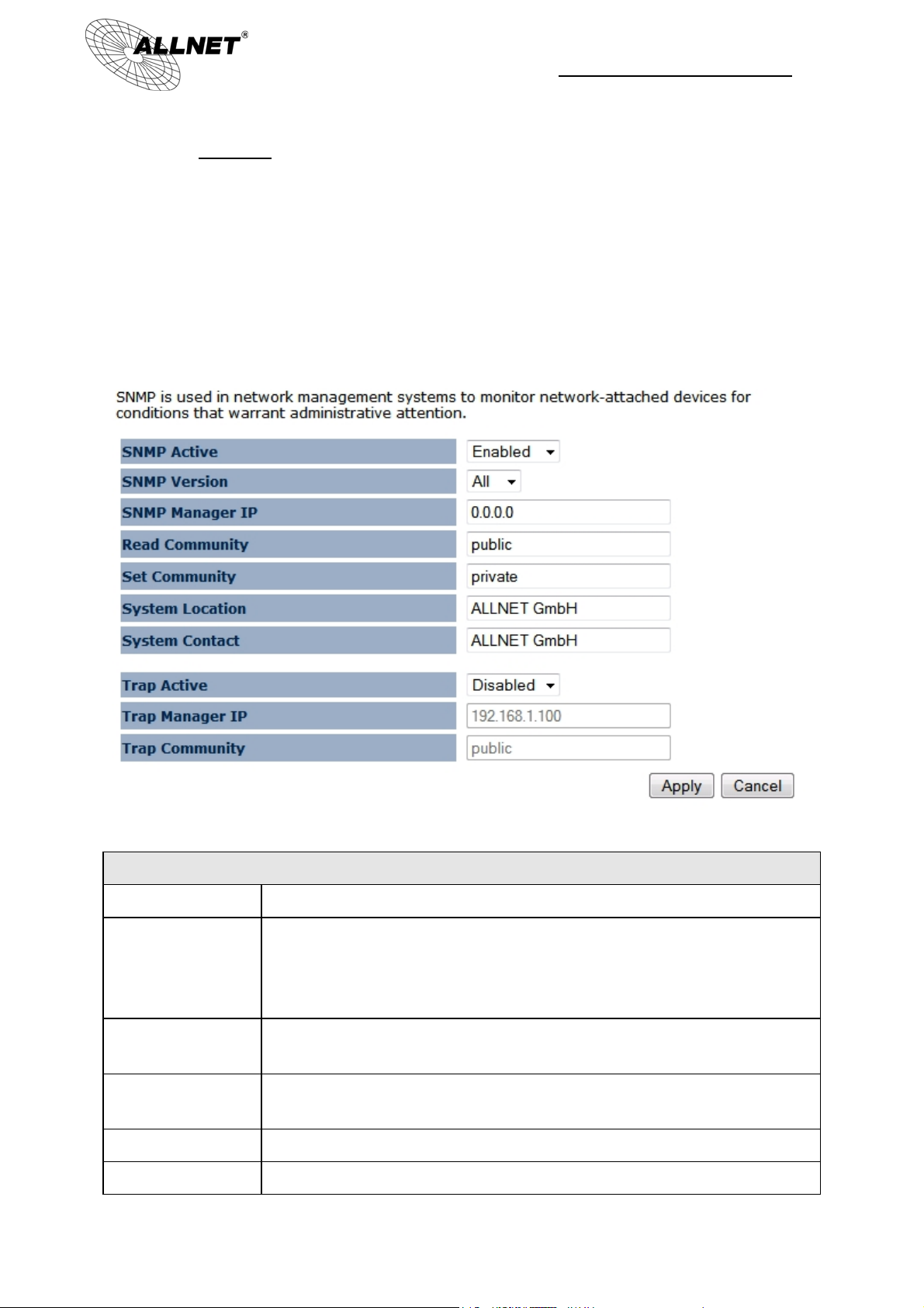
The SNMP section of the Management menu allows you to assign the contact details,
location, community name, and trap settings for the Simple Network Management
Protocol (SNMP). The SNMP is a networking management protocol used to monitor
network-attached devices. SNMP allows messages (called protocol data units) to be
sent to various parts of a network. Upon receiving these messages, SNMP-compatible
devices (Agents) return data stored in their Management Information Bases.
SNMP
SNMP Active Enable or disable the SNMP feature.
SNMP Version You may select the SNMP version you want to deploy.
All: Interoperability between SNMPv1 and SNMPv2c devices.
v1: The standard SNMP version.
v2c: Improvement in performance and security of SNMPv1.
Read Community Specify the password for access the SNMP community for read only
access.
Set Community Specify the password for access to the SNMP community with read/write
access.
System Location Specify the location of the device.
System Contact Specify the contact details of the device
82
Page 84

ALL02850N User’s Manual
Trap
Trap Ac tive Enable or disable SNMP trapping feature.
Trap M a nager IP Specify the IP address of the computer that will receive the SNMP traps.
Trap Community Specify the password for the SNMP trap community.
83
Page 85
ALL02850N User’s Manual
10.3 Firmware Upgrade
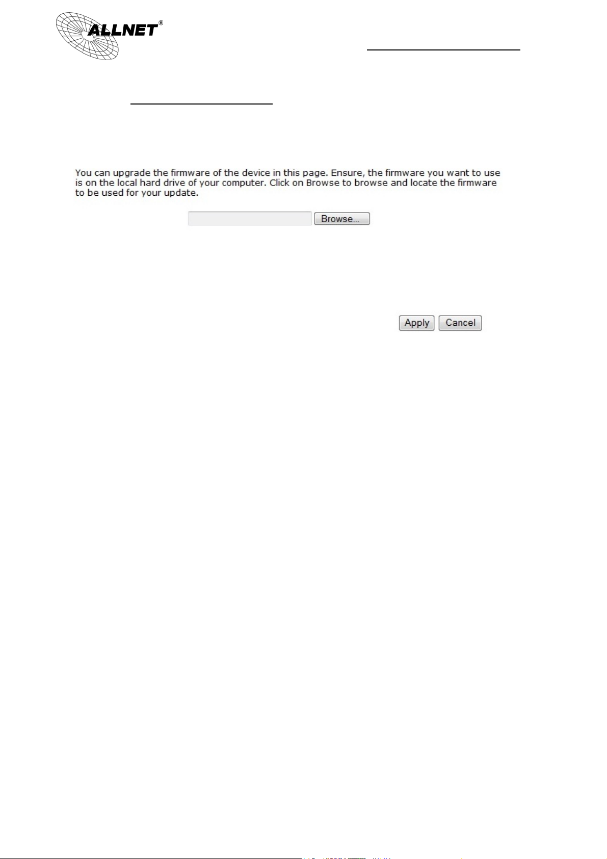
The Firmware Upgrade section of the Management allows you to upgrade the
ALL02850N's firmware.
To perform the Firmware Upgrade:
1. Download the firmware version that you want to install into the
ALL02850N and place it in a known location.
2. Click the Browse button and navigate to the location of the firmware
upgrade file.
3. Select the firmware upgrade file. Its name will appear in the Upgrade
File field.
4. Click the Apply button to commence the firmware upgrade.
Note: The device is unavailable during the upgrade process, and must restart when the upgrade is
completed. Any connections to or through the device will be lost.
84
Page 86
ALL02850N User’s Manual
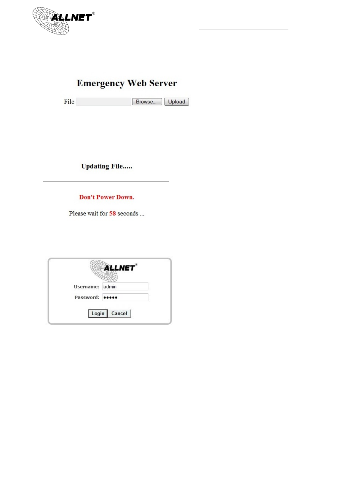
1. Click the Browse button and navigate to the location of the upgrade file and then
click Upload.
2. Wait for 60 seconds for firmware upgrade and reboot the device.
3. You can access the device again.
85
Page 87
ALL02850N User’s Manual
10.4 Configure
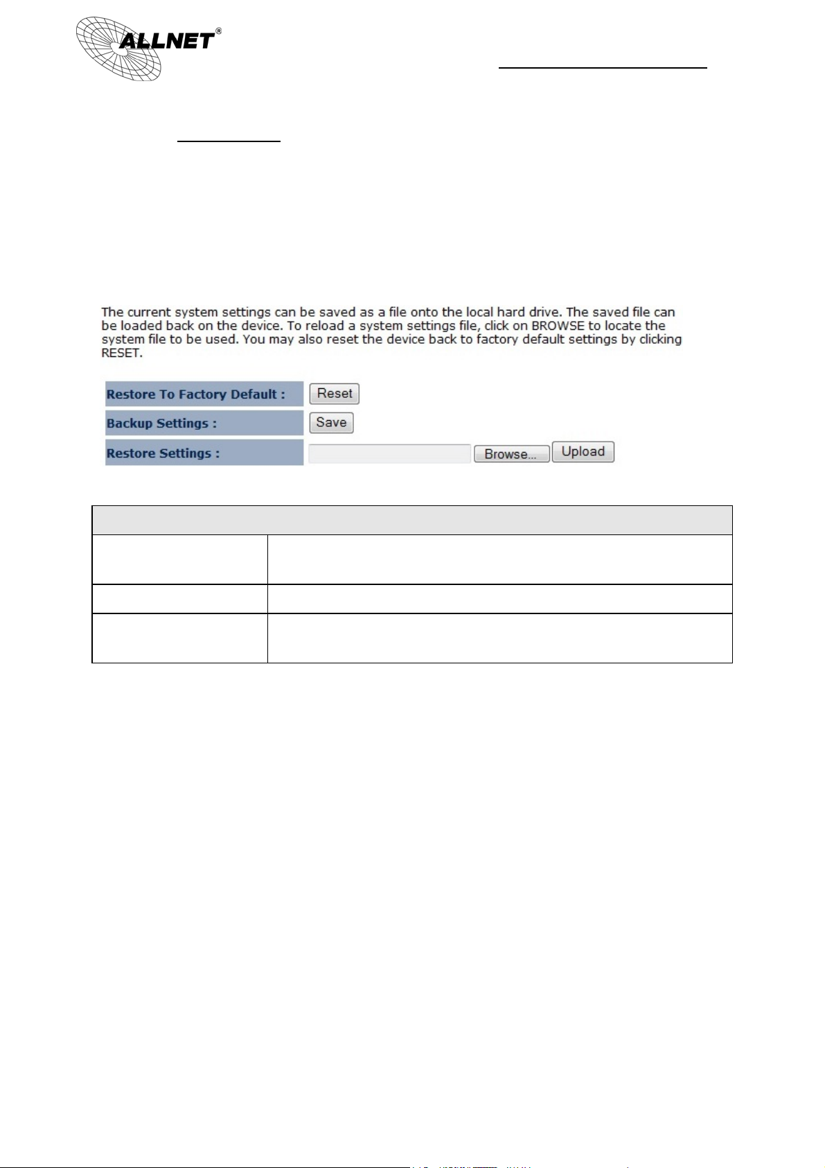
The Configure option of the Management menu allows you to save the current
device configurations. When you save the configurations, you also can re-load the
saved configurations into the device through the Restore Settings. If extreme
problems occur press the Reset button of the Restore to Factory Defaults option to
set all configurations to its original default settings.
Configure
Restore to Factory
Default
Backup Settings Save the current configuration settings to a file.
Restore Settings Restores a previously saved configuration file.
Restores the device to factory default settings.
Click Browse to select the file. Then Upload to load the settings.
86
Page 88

ALL02850N User’s Manual
10.5 Reset
In some circumstances it may be required to force the device to reboot. Click on
Apply to reboot of the Reset option of the Management menu.
87
Page 89
ALL02850N User’s Manual
11 Tools
11.1 Time Setting
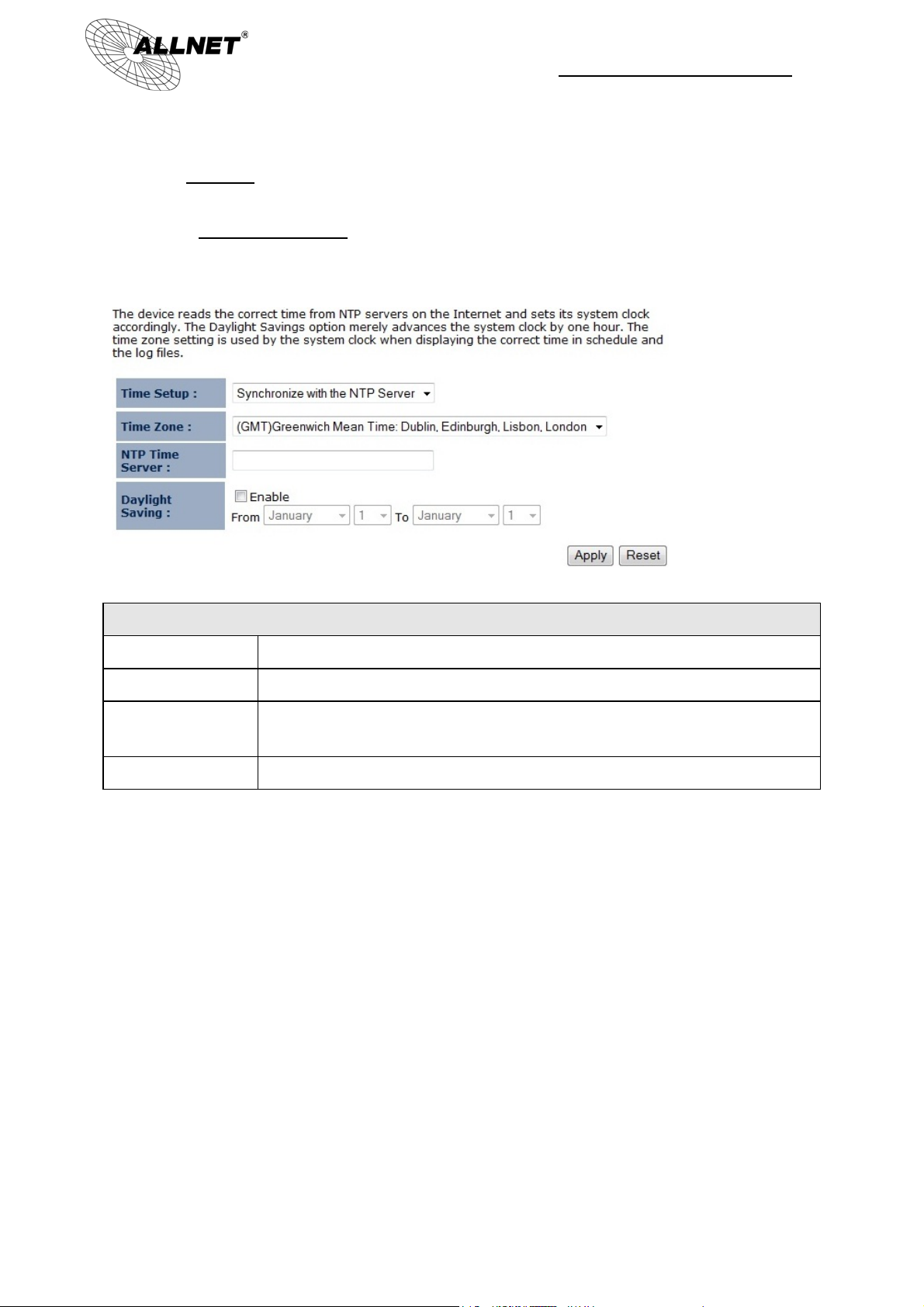
The Time Setting section of the Tools menu allows you to set the ALL02850N’s time.
Time
Time Setup Select the method you want to set the time.
Time Zone Select the time zone for your current location.
NTP Time Server Enter the address of the Network Time Protocol (NTP) Server to
automatically synchronize with a server on the Internet.
Daylight Savings Check whether daylight savings applies to your area.
88
Page 90
ALL02850N User’s Manual
11.2 Diagnosis
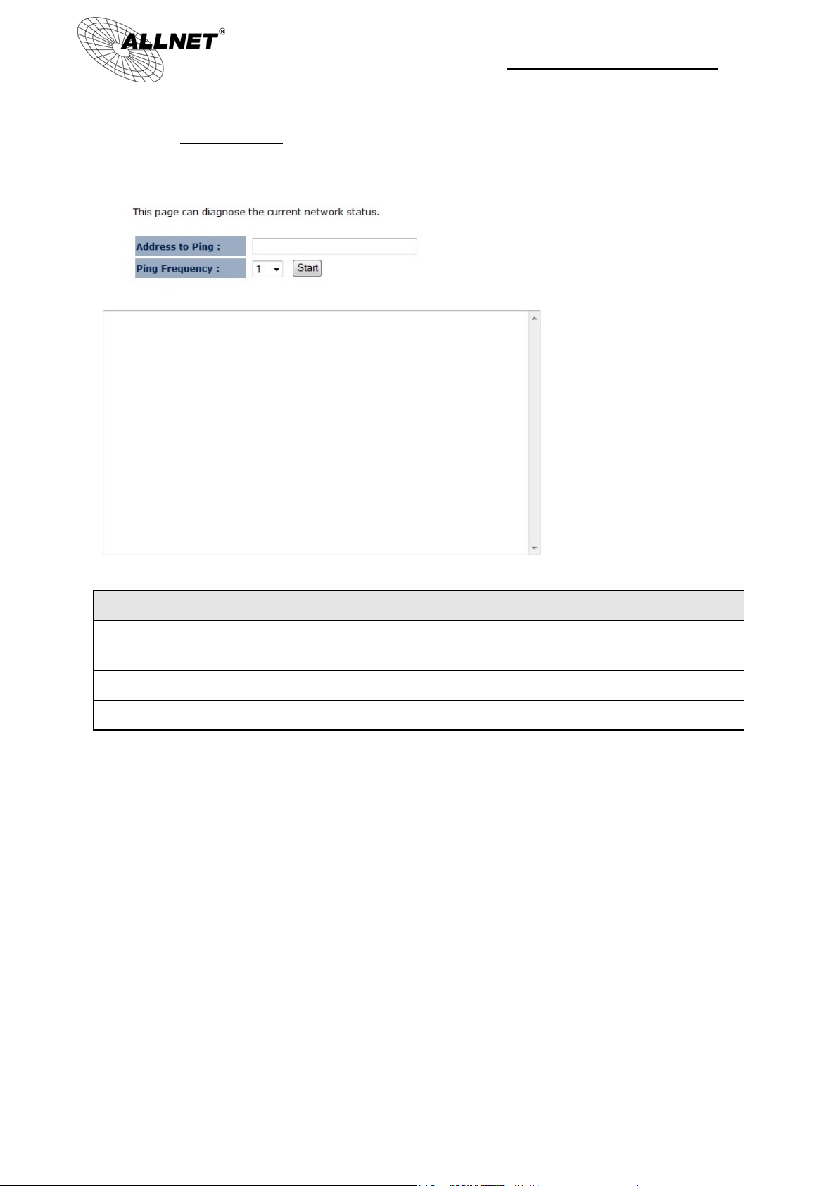
The Diagnosis section of the Tools menu allows you to test your network. Type in the
IP Address of the device for diagnosis.
Diagnosis
Address to Ping Enter the IP address you like to see if a successful connection can be
made.
Ping Frequency Select the frequency for Ping test.
Ping Result The results of the Ping test.
89
Page 91

12 Logout
Click on Logout button to logout of the ALL02850N.
ALL02850N User’s Manual
90
Page 92

ALL02850N User’s Manual
Appendix A – FCC Interference Statement
Federal Communication Commission Interference
Statement
This equipment has been tested and found to comply with the limits for a Class B digital device,
pursuant to Part 15 of the FCC Rules. These limits are designed to provide reasonable protection
against harmful interference in a residential installation. This equipment generates, uses and can
radiate radio frequency energy and, if not installed and used in accordance with the instructions, may
cause harmful interference to radio communications. However, there is no guarantee that
interference will not occur in a particular installation. If this equipment does cause harmful
interference to radio or television reception, which can be determined by turning the equipment off
and on, the user is encouraged to try to correct the interference by one of the following measures:
- Reorient or relocate the receiving antenna.
- Increase the separation between the equipment and receiver.
- Connect the equipment into an outlet on a circuit different from that to
which the receiver is connected.
- Consult the dealer or an experienced radio/TV technician for help.
FCC Caution: Any changes or modifications not expressly approved by the party responsible for
compliance could void the user's authority to operate this equipment.
This device complies with Part 15 of the FCC Rules. Operation is subject to the following two conditions:
(1) This device may not cause harmful interference, and (2) this device must accept any interference
received, including interference that may cause undesired operation.
This transmitter must not be co-located or operating in conjunction with any other antenna or
transmitter.
IMPORTANT NOTE:
FCC Radiation Exposure Statement:
This equipment complies with FCC radiation exposure limits set forth for an uncontrolled environment.
This equipment should be installed and operated with minimum distance 20cm between the radiator &
your body.
Note: The country code selection is for non-US model only and is not available to all US model. Per FCC
regulation, all WiFi product marketed in US must fixed to US operation channels only.
91
Page 93

ALL02850N User’s Manual
Appendix B – IC Interference Statement
Industry Canada statement:
This device complies with RSS-210 of the Industry Canada Rules. Operation is subject to the following
two conditions: (1) This device may not cause harmful interference, and (2) this device must accept any
interference received, including interference that may cause undesired operation.
Ce dispositif est conforme à la norme CNR-210 d'Industrie Canada applicable aux appareils radio
exempts de licence. Son fonctionnement est sujet aux deux conditions suivantes: (1) le dispositif ne
doit pas produire de brouillage préjudiciable, et (2) ce dispositif doit accepter tout brouillage reçu, y
compris un brouillage susceptible de provoquer un fonctionnement indésirable.
IMPORTANT NOTE:
Radiation Exposure Statement:
This equipment complies with IC radiation exposure limits set forth for an uncontrolled environment.
This equipment should be installed and operated with minimum distance 20cm between the radiator &
your body.
NOTE IMPORTANTE: (Pour l'utilisation de dispositifs mobiles)
Déclaration d'exposition aux radiations:
Cet équipement est conforme aux limites d'exposition aux rayonnements IC établies pour un
environnement non contrôlé. Cet équipement doit être installé et utilisé avec un minimum de 20 cm de
distance entre la source de rayonnement et votre corps.
This device has been designed to operate with a diople antenna have a maximum gain of [5] dB.
Antenna having a higher gain is strictly prohibited per regulations of Industry Canada. The required
antenna impedance is 50 ohms.
Under Industry Canada regulations, this radio transmitter may only operate using an antenna of a type
and maximum (or lesser) gain approved for the transmitter by Industry Canada. To reduce potential
radio interference to other users, the antenna type and its gain should be so chosen that the equivalent
isotropically radiated power (e.i.r.p.) is not more than that necessary for successful communication.
This radio transmitter (IC: 10103A-ALL02850N / Model: ALL02850N) has been approved by Industry
Canada to operate with the antenna type, maximum permissible gain and required antenna impedance
for each antenna type indicated. Antenna types not included in this user’s manual, having a gain
greater than the maximum gain indicated for that type, are strictly prohibited for use with this device.
Ce dispositif a été conçu pour fonctionner avec une antenne ayant un gain maximal de diople antenne
avec dB [5]. Une antenne à gain plus élevé est strictement interdite par les règlements d'Industrie
Canada. L'impédance d'antenne requise est de 50 ohms.
Conformément à la réglementation d'Industrie Canada, le présent émetteur radio peutfonctionner avec
une antenne d'un type et d'un gain maximal (ou inférieur) approuvé pourl'émetteur par Industrie
92
Page 94

93
Canada. Dans le but de réduire les risques de brouillage radioélectriqueà l'intention des autres
utilisateurs, il faut choisir le type d'antenne et son gain de sorte que lapuissance isotrope rayonnée
équivalente (p.i.r.e.) ne dépasse pas l'intensité nécessaire àl'établissement d'une communication
satisfaisante.
Le présent émetteur radio (IC: 10103A-ALL02850N / Modèle: ALL02850N) a été approuvé par Industrie
Canada pour fonctionner avec les types d'antenne énumérés ci-dessous et ayant un gain admissible
maximal et l'impédance requise pour chaque type d'antenne. Les types d'antenne non inclus dans cette
liste, ou dont le gain est supérieur au gain maximal indiqué, sont strictement interdits pour
l'exploitation de l'émetteur.
Page 95

ALL02850N User’s Manual
Appendix C – CE Interference Statement
Europe – EU Declaration of Conformity
This device complies with the essential requirements of the R&TTE Directive 1999/5/EC. The following
test methods have been applied in order to prove presumption of conformity with the essential
requirements of the R&TTE Directive 1999/5/EC:
- EN60950-1:2006 A11:2009+A1:2010
- Safety of Information Technology Equipment
- EN50385 : 2002
- Generic standard to demonstrate the compliance of electronic and electrical
apparatus with the basic restrictions related to human exposure to
electromagnetic fields (0 Hz - 300 GHz)
- EN 300 328 V1.7.1: 2006-10
- Electromagnetic compatibility and Radio spectrum Matters (ERM);
Wideband Transmission systems; Data transmission equipment operating in
the 2,4 GHz ISM band and using spread spectrum modulation techniques;
Harmonized EN covering essential requirements under article 3.2 of the
R&TTE Directive
- EN 301 489-1 V1.8.1: 2008-04
- Electromagnetic compatibility and Radio Spectrum Matters (ERM);
ElectroMagnetic Compatibility (EMC) standard for radio equipment and
services; Part 1: Common technical requirements
- EN 301 489-17 V2.1.1 2009-05
- Electromagnetic compatibility and Radio spectrum Matters (ERM);
ElectroMagnetic Compatibility (EMC) standard for radio equipment and
services; Part 17: Specific conditions for 2,4 GHz wideband transmission
systems and 5 GHz high performance RLAN equipment
This device is a 2.4 GHz wideband transmission system (transceiver), intended for use in all EU member
0
Page 96

ALL02850N User’s Manual
states and EFTA countries, except in France and Italy where restrictive use applies.
In Italy the end-user should apply for a license at the national spectrum authorities in order to obtain
authorization to use the device for setting up outdoor radio links and/or for supplying public access to
telecommunications and/or network services.
This device may not be used for setting up outdoor radio links in France and in some areas the RF
output power may be limited to 10 mW EIRP in the frequency range of 2454 – 2483.5 MHz. For detailed
information the end-user should contact the national spectrum authority in France.
0560
Česky [Czech] [Jméno výrobce] tímto prohlašuje, že tento [typ zařízení] je ve
shodě se základními požadavky a dalšími příslušnými
ustanoveními směrnice 1999/5/ES.
Dansk [Danish] Undertegnede [fabrikantens navn] erklærer herved, at følgende
udstyr [udstyrets typebetegnelse] overholder de væsentlige krav
og øvrige relevante krav i direktiv 1999/5/EF.
Deutsch
[German]
Eesti [Estonian] Käesolevaga kinnitab [tootja nimi = name of manufacturer]
English Hereby, [name of manufacturer], declares that this [type of
Hiermit erklärt [Name des Herstellers], dass sich das Gerät
[Gerätetyp] in Übereinstimmung mit den grundlegenden
Anforderungen und den übrigen einschlägigen Bestimmungen
der Richtlinie 1999/5/EG befindet.
seadme [seadme tüüp = type of equipment] vastavust direktiivi
1999/5/EÜ põhinõuetele ja nimetatud direktiivist tulenevatele
teistele asjakohastele sätetele.
equipment] is in compliance with the essential requirements and
other relevant provisions of Directive 1999/5/EC.
Español
[Spanish]
Ελληνική
[Greek]
Por medio de la presente [nombre del fabricante] declara que el
[clase de equipo] cumple con los requisitos esenciales y
cualesquiera otras disposiciones aplicables o exigibles de la
Directiva 1999/5/CE.
ΜΕ ΤΗΝ ΠΑΡΟΥΣΑ [name of manufacturer] ∆ΗΛΩΝΕΙ ΟΤΙ [type of
equipment] ΣΥΜΜΟΡΦΩΝΕΤΑΙ ΠΡΟΣ ΤΙΣ ΟΥΣΙΩ∆ΕΙΣ ΑΠΑΙΤΗΣΕΙΣ
1
Page 97

ALL02850N User’s Manual
ΚΑΙ ΤΙΣ ΛΟΙΠΕΣ ΣΧΕΤΙΚΕΣ ∆ΙΑΤΑΞΕΙΣ ΤΗΣ Ο∆ΗΓΙΑΣ 1999/5/ΕΚ.
Français
[French]
Par la présente [nom du fabricant] déclare que l'appareil [type
d'appareil] est conforme aux exigences essentielles et aux autres
dispositions pertinentes de la directive 1999/5/CE.
Italiano [Italian] Con la presente [nome del costruttore] dichiara che questo [tipo di
apparecchio] è conforme ai requisiti essenziali ed alle altre
disposizioni pertinenti stabilite dalla direttiva 1999/5/CE.
Latviski
[Latvian]
Ar šo [name of manufacturer / izgatavotāja nosaukums] deklarē,
ka [type of equipment / iekārtas tips] atbilst Direktīvas 1999/5/EK
būtiskajām prasībām un citiem ar to saistītajiem noteikumiem.
Lietuvių
[Lithuanian]
Šiuo [manufacturer name] deklaruoja, kad šis [equipment type]
atitinka esminius reikalavimus ir kitas 1999/5/EB Direktyvos
nuostatas.
Nederlands
[Dutch]
Hierbij verklaart [naam van de fabrikant] dat het toestel [type van
toestel] in overeenstemming is met de essentiële eisen en de
andere relevante bepalingen van richtlijn 1999/5/EG.
Malti [Maltese] Hawnhekk, [isem tal-manifattur], jiddikjara li dan [il-mudel
tal-prodott] jikkonforma mal-ħtiġijiet essenzjali u ma
provvedimenti oħrajn relevanti li hemm fid-Dirrettiva 1999/5/EC.
Magyar
[Hungarian]
Alulírott, [gyártó neve] nyilatkozom, hogy a [... típus] megfelel a
vonatkozó alapvetõ követelményeknek és az 1999/5/EC irányelv
egyéb elõírásainak.
Polski [Polish] Niniejszym [nazwa producenta] oświadcza, że [nazwa wyrobu] jest
zgodny z zasadniczymi wymogami oraz pozostałymi stosownymi
postanowieniami Dyrektywy 1999/5/EC.
Português
[Portuguese]
[Nome do fabricante] declara que este [tipo de equipamento] está
conforme com os requisitos essenciais e outras disposições da
Directiva 1999/5/CE.
Slovensko
[Slovenian]
[Ime proizvajalca] izjavlja, da je ta [tip opreme] v skladu z
bistvenimi zahtevami in ostalimi relevantnimi določili direktive
1999/5/ES.
Slovensky
[Slovak]
[Meno výrobcu] týmto vyhlasuje, že [typ zariadenia] spĺňa
základné požiadavky a všetky príslušné ustanovenia Smernice
1999/5/ES.
Suomi [Finnish] [Valmistaja = manufacturer] vakuuttaa täten että [type of
equipment = laitteen tyyppimerkintä] tyyppinen laite on
direktiivin 1999/5/EY oleellisten vaatimusten ja sitä koskevien
direktiivin muiden ehtojen mukainen.
2
Page 98

ALL02850N User’s Manual
Svenska
[Swedish]
Härmed intygar [företag] att denna [utrustningstyp] står I
överensstämmelse med de väsentliga egenskapskrav och övriga
relevanta bestämmelser som framgår av direktiv 1999/5/EG.
3
Page 99

ALL02850N User’s Manual
CE-Declaration of Conformity
For the following equipment:
Germering, 1st of August, 2013
WLAN N Access Point /Client Bridge
ALL02850N
The safety advice in the documentation accompanying the
products shall be obeyed. The conformity to the above
directive is indicated by the CE sign on the device.
The ALLNET ALL02850N conforms to the Council EM C Directives of 2006/95/EC.
This equipment meets the following conformance standards:
EN 60950-1:2006 +A11:2009 + A1:2010 + A12:2011
This equipment is intended to be operated in all countries.
This declaration is made by
ALLNET Computersysteme GmbH
Maistraße 2
82110 Germering
Germany
Germering, 01.08.2013
4
 Loading...