

Page 1
Installation Guide
Pleasegoto our website for product cleaning tips. Go to the
ToolsRequired: Flathead screwdriver,Phillipsscrewdriver,pliers, wire cutters, wire strippers, electrical tape, safety glasses.
LightSource:
EstimatedAssembly Time:
Preparation:
present.Ifanypartsaremissingordamaged,donotattempttoassemble,install,oroperatethefixture.Contactyouroriginalplaceofpurchase.
LED14W
20-30minutes
Identifyandinspectallpartsbeforebeginninginstallation.Checkpackagecontentlistanddiagramsbelowtoensureallpartsare
Care + Maintena nce
selection.
Warnings and Cautions
Turn off electricity at circuit breaker or main fuse box before installation. Consult a licensed electrician if in doubt.
These instructions are provided for your safety. It is very important you read them completely before installing the fixture. We strongly
recommend that a licensed, professional electrician perform the installation.
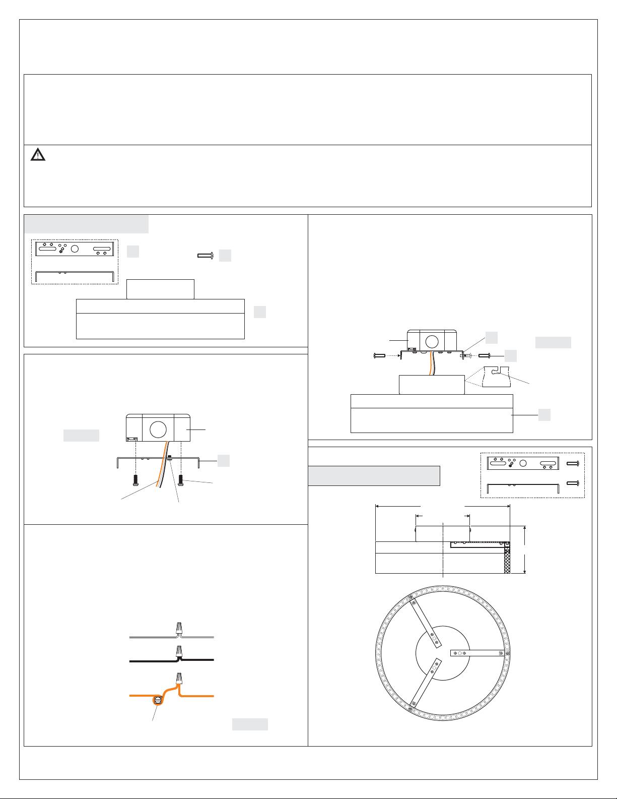
Package Contents
Crossbar
A
x1
STEP 1 - Install the Crossbar to the junction box
Mounting Screw
B
x2
C
Fixture
Body
x1
STEP 3 - Install the Fixture Body to Crossbar
A. Thread Mounting Screws (B) into mounting holes on the side of the
Crossbar (A). Do not thread all screws in.
B. Carefully tuck all wires into the outlet box. Fit the “L” slots on the
ceiling canopy with the Mounting Screws (B) and rotate the Fixture
Body (C) until it is hung safety on Mounting Screws (B).
C. By using screwdrivers, tighten Mounting Screws (B) until snug to
secure the Fixture Body (C).
Your fixture is now assembled and ready to use. Enjoy!
Outlet Box
A
Figure 3
B
A. Attach the Crossbar (A) to the outlet box with the head of the green
ground screw facing you. Secure it with outlet box screws (not
included), tighten until snug.
Figure 1
Supply Wires and
Ground Wire
STEP 2 - Wire Connections
A. Wrap bare or green ground wire around green ground screw on the
crossbar, no less than 2 inches from the end of the wire. Tighten the
green ground screw.
B. Use standard wire connectors (not included) to make all wire
connections. Twist connectors until wires are tightly joined together.
Wrap each connection with approved electrical tape and carefully
stuff all the connected wires into the Outlet Box.
White wire
from outlet box
Black wire from
outlet box (or Red)
Green Ground Screw
Outlet Box
A
Outlet Box Screws
(not included)
White wire
from fixture
Black wire
from fixture
“L” Slot
C
FINISH: OIL RUBBED BRONZE
11.75” Dia.
4.75” Dia.
4”
Bare, or Green
Ground wire
from outlet box
Green Ground Screw
on the Crossbar
Ground wire
from Fixture
Figure 2
NOTE: ALL DIMENSIONS ARE ROUNDED UP
TO THE NEAREST 1/4"
1of1
 Loading...