

Allied Vision Technologies F-100B/C fiber, F-032B/C fiber, F-145B/C fiber, F-145B/C-15fps, F-210B/C Technical Manual
...Page 1

AVT Pike
Allied Vision Technologies GmbH
Taschenweg 2a
D-07646 Stadtroda / Germany
Technical Manual
V5.0.0
07 May 2010
Page 2

Legal notice
For customers in the U.S.A.
This equipment has been tested and found to comply with the limits for a Class B digital
device, pursuant to Part 15 of the FCC Rules. These limits are designed to provide reasonable
protection against harmful interference when the equipment is operated in a residential environment. This equipment generates, uses, and can radiate radio frequency energy and, if not
installed and used in accordance with the instruction manual, may cause harmful interference
to radio communications. However there is no guarantee that interferences will not occur in
a particular installation. If the equipment does cause harmful interference to radio or television reception, the user is encouraged to try to correct the interference by one or more of the
following measures:
• Reorient or relocate the receiving antenna.
• Increase the distance between the equipment and the receiver.
• Use a different line outlet for the receiver.
• Consult a radio or TV technician for help.
You are cautioned that any changes or modifications not expressly approved in this manual
could void your authority to operate this equipment. The shielded interface cable recommended in this manual must be used with this equipment in order to comply with the limits
for a computing device pursuant to Subpart B of Part 15 of FCC Rules.
For customers in Canada
This apparatus complies with the Class B limits for radio noise emissions set out in the Radio
Interference Regulations.
Pour utilisateurs au Canada
Cet appareil est conforme aux normes classe B pour bruits radioélectriques, spécifiées dans le
Règlement sur le brouillage radioélectrique.
Life support applications
These products are not designed for use in life support appliances, devices, or systems where
malfunction of these products can reasonably be expected to result in personal injury. Allied
customers using or selling these products for use in such applications do so at their own risk
and agree to fully indemnify Allied for any damages resulting from such improper use or sale.
Trademarks
Unless stated otherwise, all trademarks appearing in this document of Allied Vision
Technologies are brands protected by law.
Warranty
The information provided by Allied Vision Technologies is supplied without any guarantees or
warranty whatsoever, be it specific or implicit. Also excluded are all implicit warranties concerning the negotiability, the suitability for specific applications or the non-breaking of laws
and patents. Even if we assume that the information supplied to us is accurate, errors and
inaccuracy may still occur.
Copyright
All texts, pictures and graphics are protected by copyright and other laws protecting intellectual property. It is not permitted to copy or modify them for trade use or transfer, nor may
they be used on web sites.
Allied Vision Technologies GmbH 05/2010
All rights reserved.
Managing Director: Mr. Frank Grube
Tax ID: DE 184383113
Headquarters:
Taschenweg 2A
D-07646 Stadtroda, Germany
Tel.: +49 (0)36428 6770
Fax: +49 (0)36428 677-28
e-mail: info@alliedvisiontec.com
PIKE Technical Manual V5.0.0
2
Page 3

Contents
Contacting Allied Vision Technologies ..................................................11
Introduction ...........................................................................................................12
Document history ......................................................................................................... 12
Manual overview........................................................................................................... 22
Conventions used in this manual..................................................................................... 24
Styles ..................................................................................................................... 24
Symbols .................................................................................................................. 24
More information.......................................................................................................... 25
Before operation .......................................................................................................... 25
PIKE cameras .......................................................................................................27
Conformity ..............................................................................................................29
CE...................................................................................................................... 29
FCC – Class B Device ............................................................................................. 29
FireWire....................................................................................................................30
Overview ..................................................................................................................... 30
Definition ............................................................................................................... 30
IEEE 1394 standards ................................................................................................. 30
Why use FireWire? .................................................................................................... 31
FireWire in detail.......................................................................................................... 31
Serial bus................................................................................................................ 31
FireWire connection capabilities ................................................................................. 33
Capabilities of 1394a (FireWire 400)............................................................................ 33
IIDC V1.3 camera control standards ........................................................................ 33
Capabilities of 1394b (FireWire 800) ........................................................................... 34
IIDC V1.31 camera control standards ...................................................................... 34
Compatibility between 1394a and 1394b...................................................................... 35
Compatibility example .......................................................................................... 35
Image transfer via 1394a and 1394b ........................................................................... 36
1394b bandwidths.................................................................................................... 37
Requirements for PC and 1394b.............................................................................. 37
Requirements for laptop and 1394b ........................................................................ 38
Example1: 1394b bandwidth of PIKE cameras ........................................................... 40
Example 2: More than one PIKE camera at full speed ................................................. 41
FireWire Plug & play capabilities................................................................................. 42
FireWire hot-plug and screw-lock precautions ............................................................... 42
Screw-lock and power supply precautions..................................................................... 43
Operating system support .......................................................................................... 44
Filter and lenses .................................................................................................45
IR cut filter: spectral transmission .................................................................................. 45
PIKE Technical Manual V5.0.0
3
Page 4

Camera lenses.......................................................................................................... 46
Camera dimensions ..........................................................................................48
Serial numbers for starting new front flange................................................................. 48
PIKE standard housing (2 x 1394b copper) ....................................................................... 49
PIKE (1394b: 1 x GOF, 1 x copper)................................................................................... 50
Tripod adapter ............................................................................................................. 51
Pike W90 (2 x 1394b copper).......................................................................................... 52
Pike W90 (1394b: 1 x GOF, 1 x copper) ............................................................................ 53
Pike W90 S90 (2 x 1394b copper).................................................................................... 54
Pike W90 S90 (1394b: 1 x GOF, 1 x copper) ...................................................................... 55
Pike W270 (2 x 1394b copper)........................................................................................ 56
Pike W270 (1394b: 1 x GOF, 1 x copper)........................................................................... 57
Pike W270 S90 (2 x 1394b copper) .................................................................................. 58
Pike W270 S90 (1394b: 1 x GOF, 1 x copper)..................................................................... 59
Cross section: CS-Mount (only PIKE F-032B/C) .................................................................. 60
Cross section: C-Mount (VGA size filter) ........................................................................... 61
Cross section: C-Mount (large filter) ................................................................................ 62
Adjustment of C-Mount.................................................................................................. 63
Adjustment of F-Mount for Pike F-1100 and Pike F-1600..................................................... 64
F-Mount ...................................................................................................................... 64
Pike F-Mount: standard housing
(2 x 1394b copper)................................................................................................... 65
Pike F-Mount: Tripod adapter ..................................................................................... 66
Pike F-Mount: W270 (2 x 1394b copper) ...................................................................... 67
Cross section: F-Mount .............................................................................................. 68
K-Mount, M39-Mount .................................................................................................... 69
Cross section: M39-Mount.......................................................................................... 69
M42-Mount .................................................................................................................. 70
Pike M42-Mount: standard housing
(2 x 1394b copper)................................................................................................... 70
Pike M42-Mount: Tripod adapter ................................................................................. 71
Pike M42-Mount: W270 (2 x 1394b copper) .................................................................. 72
Cross section: M42-Mount.......................................................................................... 73
M58-Mount .................................................................................................................. 74
Pike M58-Mount: standard housing
(2 x 1394b copper)................................................................................................... 74
Pike M58-Mount: Tripod adapter ................................................................................. 75
Pike M58-Mount: W270 (2 x 1394b copper) .................................................................. 76
Cross section: M58-Mount.......................................................................................... 77
Specifications .......................................................................................................78
PIKE F-032B/C (fiber).................................................................................................... 78
PIKE F-100B/C (fiber).................................................................................................... 80
PIKE F-145B/C (fiber) (-15fps*)...................................................................................... 82
PIKE F-210B/C (fiber).................................................................................................... 84
PIKE F-421B/C (fiber).................................................................................................... 86
PIKE Technical Manual V5.0.0
4
Page 5

PIKE F-505B/C (fiber).................................................................................................... 88
PIKE F-1100B/C (fiber) .................................................................................................. 90
PIKE F-1600B/C (fiber) .................................................................................................. 92
Spectral sensitivity ....................................................................................................... 94
Camera interfaces ...........................................................................................103
IEEE 1394b port pin assignment ................................................................................... 103
Camera I/O connector pin assignment ........................................................................... 105
Status LEDs................................................................................................................ 106
On LED (green) ...................................................................................................... 106
Status LED............................................................................................................. 106
Control and video data signals...................................................................................... 108
Inputs .................................................................................................................. 108
Triggers............................................................................................................ 108
Input/output pin control......................................................................................... 109
IO_INP_CTRL 1-2 ............................................................................................... 110
Trigger delay ..................................................................................................... 111
Outputs ................................................................................................................ 113
IO_OUTP_CTRL 1-4 ............................................................................................. 114
Output modes.................................................................................................... 115
Pulse-width modulation .......................................................................................... 117
PWM: minimal and maximal periods and frequencies ............................................... 118
PWM: Examples in practice .................................................................................. 119
Pixel data.................................................................................................................. 120
Description of the data path...................................................................... 123
Block diagrams of the cameras ..................................................................................... 123
Black and white cameras ......................................................................................... 123
Color cameras ........................................................................................................ 124
Channel balance ......................................................................................................... 125
Channel adjustment with SmartView (>1.5)................................................................ 125
Dual-tap offset adjustment with SmartView (1.10 or greater).................................... 126
White balance ............................................................................................................ 128
One-push white balance .......................................................................................... 130
Auto white balance (AWB) ..................................................................................... 132
Auto shutter .............................................................................................................. 133
Auto gain .................................................................................................................. 135
Manual gain............................................................................................................... 138
Brightness (black level or offset) .................................................................................. 139
Horizontal mirror function ........................................................................................... 140
Shading correction...................................................................................................... 142
Building shading image in Format_7 modes ............................................................... 142
First example .................................................................................................... 142
Second example................................................................................................. 142
How to store shading image..................................................................................... 143
Automatic generation of correction data.................................................................... 144
Requirements .................................................................................................... 144
Algorithm ......................................................................................................... 144
PIKE Technical Manual V5.0.0
5
Page 6

Loading a shading image out of the camera ............................................................... 147
Loading a shading image into the camera .................................................................. 148
Look-up table (LUT) and gamma function....................................................................... 149
Loading an LUT into the camera ............................................................................... 151
Binning (only Pike b/w models).................................................................................... 152
2 x / 4 x / 8 x binning ............................................................................................ 152
Vertical binning ..................................................................................................... 153
Horizontal binning ................................................................................................. 155
2 x full binning/4 x full binning/8 x full binning ........................................................ 156
Sub-sampling (PIKE b/w and color) ............................................................................... 157
What is sub-sampling? ............................................................................................ 157
Which PIKE models have sub-sampling? ..................................................................... 157
Description of sub-sampling..................................................................................... 157
Binning and sub-sampling access.................................................................................. 164
Quick parameter change timing modes....................................................................... 166
Why new timing modes?.......................................................................................... 166
Standard Parameter Update Timing .................................................................... 167
New: Quick Format Change Mode (QFCM) ............................................................. 167
How to transfer parameters to the camera.................................................................. 168
Encapsulated Update (begin/end)...................................................................... 168
Parameter-List Update ...................................................................................... 169
Standard Update (IIDC)..................................................................................... 170
Packed 12-Bit Mode................................................................................................... 171
High SNR mode (High Signal Noise Ratio) ...................................................................... 172
Frame memory and deferred image transport................................................................... 173
Deferred image transport......................................................................................... 173
HoldImg mode....................................................................................................... 174
FastCapture mode................................................................................................... 176
Color interpolation (BAYER demosaicing) ....................................................................... 177
Sharpness.................................................................................................................. 178
Hue and saturation ..................................................................................................... 179
Color correction.......................................................................................................... 180
Why color correction? ......................................................................................... 180
Color correction in AVT cameras ........................................................................... 180
Color correction: formula..................................................................................... 180
GretagMacbeth ColorChecker ................................................................................ 180
Changing color correction coefficients .................................................................. 181
Switch color correction on/off ............................................................................. 181
Color conversion (RGB YUV) ..................................................................................... 182
Bulk Trigger............................................................................................................... 182
Level Trigger.............................................................................................................. 182
Serial interface........................................................................................................... 183
Controlling image capture ..........................................................................188
Trigger modi .............................................................................................................. 188
Bulk Trigger (Trigger_Mode_15)................................................................................ 190
Trigger delay ......................................................................................................... 193
PIKE Technical Manual V5.0.0
6
Page 7

Trigger delay advanced register............................................................................ 194
Debounce.............................................................................................................. 195
Debounce time....................................................................................................... 196
Exposure time (shutter) and offset ................................................................................ 197
Exposure time offset ............................................................................................... 197
Minimum exposure time .......................................................................................... 197
Extended shutter.................................................................................................... 198
One-shot ................................................................................................................... 200
One-shot command on the bus to start of exposure ..................................................... 201
End of exposure to first packet on the bus ................................................................. 202
Multi-shot ................................................................................................................. 203
ISO_Enable / free-run.................................................................................................. 203
Asynchronous broadcast .............................................................................................. 203
Jitter at start of exposure ............................................................................................ 204
Sequence mode .......................................................................................................... 206
How is sequence mode implemented?........................................................................ 207
Setup mode (new for 3.x).................................................................................... 208
Sequence step mode (new for 3.x)........................................................................ 208
SeqMode description .......................................................................................... 209
Sequence repeat counter (new for 3.x) .................................................................. 209
Manual stepping & reset (new for 3.x) .................................................................. 209
Which new sequence mode features are available?....................................................... 211
Setup mode....................................................................................................... 211
I/O controlled sequence stepping mode.............................................................. 211
I/O controlled sequence pointer reset ................................................................ 212
I/O controlled sequence stepping mode and I/O controlled sequence pointer reset via
software command ............................................................................................. 212
Points to pay attention to when working with a sequence ............................................ 212
Changing the parameters within a sequence ............................................................... 214
Points to pay attention to when changing the parameters............................................ 214
Secure image signature (SIS): definition and scenarios .................................................... 215
SIS: Definition....................................................................................................... 215
SIS: Scenarios........................................................................................................ 215
Smear reduction ......................................................................................................... 217
Smear reduction: definition ..................................................................................... 217
Smear reduction: how it works ................................................................................. 217
Smear reduction: switch on/off in register and SmartView ............................................ 217
Video formats, modes and bandwidth .................................................218
PIKE F-032B / PIKE F-032C........................................................................................... 219
PIKE F-100B / PIKE F-100C........................................................................................... 221
PIKE F-145B / PIKE F-145C (-15 fps**) .......................................................................... 223
PIKE F-210B / PIKE F-210C........................................................................................... 225
PIKE F-421B / PIKE F-421C........................................................................................... 227
PIKE F-505B / PIKE F-505C........................................................................................... 229
PIKE F-1100B / PIKE F-1100C ....................................................................................... 231
PIKE F-1600B / PIKE F-1600C ....................................................................................... 233
PIKE Technical Manual V5.0.0
7
Page 8

Area of interest (AOI) ................................................................................................. 235
Autofunction AOI ................................................................................................... 237
Frame rates................................................................................................................ 238
Frame rates Format_7 ............................................................................................. 242
PIKE F-032: AOI frame rates..................................................................................... 243
PIKE F-100: AOI frame rates..................................................................................... 244
PIKE F-145: AOI frame rates (no sub-sampling)........................................................... 245
PIKE F-145: AOI frame rates (sub-sampling) ............................................................... 246
PIKE F-145-15fps: AOI frame rates (no sub-sampl.) ..................................................... 247
PIKE F-145-15fps: AOI frame rates (sub-sampl.).......................................................... 248
PIKE F-210: AOI frame rates (no sub-sampling)........................................................... 249
PIKE F-210: AOI frame rates (sub-sampling) ............................................................... 250
PIKE F-421: AOI frame rates..................................................................................... 251
PIKE F-505: AOI frame rates..................................................................................... 252
AOI frame rates with max. BPP = 8192 .................................................................. 252
AOI frame rates with max. BPP = 11000 ................................................................ 253
PIKE F-1100: AOI frame rates ................................................................................... 254
Pike F-1100: frame rate formula single-tap ............................................................ 254
AOI frame rates maxBPP=8192, single-tap, no sub-sampling..................................... 254
AOI frame rates maxBPP=8192, single-tap, sub-sampling ......................................... 255
Pike F-1100: frame rate formula dual-tap............................................................... 256
AOI frame rates maxBPP=8192, dual-tap, no sub-sampling ....................................... 256
AOI frame rates maxBPP=8192, dual-tap, sub-sampling ........................................... 257
AOI frame rates maxBPP=11000, single-tap, no sub-sampl. ...................................... 258
AOI frame rates maxBPP=11000, single-tap, sub-sampl............................................ 259
AOI frame rates maxBPP=11000, dual-tap, no sub-sampl.......................................... 260
AOI frame rates maxBPP=11000, dual-tap, sub-sampl. ............................................. 261
PIKE F-1600: AOI frame rates ................................................................................... 262
Pike F-1600: frame rate formula single-tap ............................................................ 262
AOI frame rates maxBPP=8192, single-tap, no sub-sampling..................................... 262
AOI frame rates maxBPP=8192, single-tap, sub-sampling ......................................... 263
Pike F-1600: frame rate formula dual-tap............................................................... 264
AOI frame rates maxBPP=8192, dual-tap, no sub-sampling ....................................... 264
AOI frame rates maxBPP=8192, dual-tap, sub-sampling ........................................... 265
AOI frame rates maxBPP=11000, single-tap, no sub-sampl. ...................................... 266
AOI frame rates maxBPP=11000, single-tap, sub-sampling ....................................... 267
AOI frame rates maxBPP=11000, dual-tap, no sub-sampling ..................................... 268
AOI frame rates maxBPP=11000, dual-tap, sub-sampling.......................................... 269
How does bandwidth affect the frame rate? ...................................270
Example formula for the b/w camera..................................................................... 271
Test images ............................................................................................................... 272
Loading test images ............................................................................................... 272
Test images for b/w cameras.................................................................................... 272
Test images for color cameras .................................................................................. 273
YUV4:2:2 mode.................................................................................................. 273
Mono8 (raw data) .............................................................................................. 273
Configuration of the camera......................................................................274
PIKE Technical Manual V5.0.0
8
Page 9

Camera_Status_Register............................................................................................... 274
Example................................................................................................................ 275
Sample program ..................................................................................................... 278
Example FireGrab ............................................................................................... 278
Example FireStack API ........................................................................................ 279
Configuration ROM...................................................................................................... 280
Implemented registers................................................................................................. 283
Camera initialize register......................................................................................... 283
Inquiry register for video format............................................................................... 283
Inquiry register for video mode ................................................................................ 284
Inquiry register for video frame rate and base address ................................................. 285
Inquiry register for basic function............................................................................. 294
Inquiry register for feature presence ......................................................................... 295
Inquiry register for feature elements ......................................................................... 297
Inquiry register for absolute value CSR offset address .................................................. 300
Status and control register for feature....................................................................... 301
Feature control error status register .......................................................................... 305
Video mode control and status registers for Format_7.................................................. 305
Quadlet offset Format_7 Mode_0 .......................................................................... 305
Quadlet offset Format_7 Mode_1 .......................................................................... 305
Format_7 control and status register (CSR) ............................................................ 305
Advanced features ...................................................................................................... 307
Extended version information register ....................................................................... 311
Advanced feature inquiry......................................................................................... 313
Camera status ........................................................................................................ 315
Maximum resolution ............................................................................................... 316
Time base ............................................................................................................. 316
Extended shutter.................................................................................................... 318
Test images ........................................................................................................... 319
Look-up tables (LUT) .............................................................................................. 320
Loading a look-up table into the camera ............................................................... 321
Shading correction ................................................................................................. 322
Reading or writing shading image from/into the camera .......................................... 324
Automatic generation of a shading image.............................................................. 324
Non-volatile memory operations........................................................................... 324
Memory channel error codes ................................................................................ 325
Deferred image transport......................................................................................... 326
Frame information.................................................................................................. 327
Input/output pin control......................................................................................... 327
Delayed Integration enable...................................................................................... 328
Auto shutter control ............................................................................................... 329
Auto gain control................................................................................................... 330
Autofunction AOI ................................................................................................... 331
Color correction ..................................................................................................... 332
Trigger delay ......................................................................................................... 333
Mirror image.......................................................................................................... 333
AFE channel compensation (channel balance)............................................................. 334
Dual-tap offset adjustment ...................................................................................... 334
PIKE Technical Manual V5.0.0
9
Page 10

Soft reset.............................................................................................................. 335
High SNR mode (High Signal Noise Ratio) .................................................................. 336
Maximum ISO packet size ........................................................................................ 337
Quick parameter change timing modes ...................................................................... 339
Standard Parameter Update Timing .................................................................... 339
Quick Format Change Mode................................................................................ 339
Automatic reset of the UpdActive flag................................................................... 340
Low-noise binning mode (only 2 x H-binning) ............................................................ 340
Software feature control (disable LEDs / switch single-tap and dual-tap) ........................ 341
Disable LEDs...................................................................................................... 341
Sensor digitization taps (Pike F-1100/1600 only)........................................................ 342
Parameter-List Update ............................................................................................ 343
Format_7 mode mapping ......................................................................................... 344
Example ........................................................................................................... 345
Secure image signature (SIS) ................................................................................... 346
Advanced register: SIS........................................................................................ 346
Advanced register: frame counter ......................................................................... 348
Advanced register: trigger counter........................................................................ 349
Where to find time stamp, frame counter and trigger counter in the image................. 350
Where to find all SIS values in the image .............................................................. 350
Smear reduction..................................................................................................... 351
User profiles.......................................................................................................... 352
Error codes ....................................................................................................... 353
Reset of error codes ........................................................................................... 353
Stored settings .................................................................................................. 354
Frame time control ................................................................................................. 355
GPDATA_BUFFER..................................................................................................... 357
Little endian vs. big endian byte order.................................................................. 357
User adjustable gain references ................................................................................ 358
Firmware update............................................................................................... 359
Extended version number (FPGA/µC).............................................................................. 359
Appendix................................................................................................................361
Sensor position accuracy of AVT cameras........................................................................ 361
Index......................................................................................................................... 362
PIKE Technical Manual V5.0.0
10
Page 11

Contacting Allied Vision Technologies
Contacting Allied Vision Technologies
Info
• Technical information:
http://www.alliedvisiontec.com
• Support:
support@alliedvisiontec.com
Allied Vision Technologies GmbH (Headquarters)
Taschenweg 2a
07646 Stadtroda, Germany
Tel.: +49.36428.677-0
Fax.: +49.36428.677-28
e-mail: info@alliedvisiontec.com
Allied Vision Technologies Canada Inc.
101-3750 North Fraser Way
Burnaby, BC, V5J 5E9, Canada
Tel: +1 604-875-8855
Fax: +1 604-875-8856
e-mail: info@alliedvisiontec.com
Allied Vision Technologies Inc.
38 Washington Street
Newburyport, MA 01950, USA
Toll Free number +1-877-USA-1394
Tel.: +1.978.2252030
Fax: +1.978.2252029
e-mail: info@alliedvisiontec.com
PIKE Technical Manual V5.0.0
11
Page 12

Introduction
Introduction
Document history
Version Date Remarks
V2.0.0 07.07.2006 New Manual - RELEASE status
PRE_V3.0.0 22.09.2006 Minor corrections
Added Pike F-145
Pike F-210 AOI frame rates corrected: Chapter PIKE F-210: AOI
frame rates (no sub-sampling) on page 249
New advanced registers: Chapter Advanced features on page
307
V3.0.1 29.09.2006 Minor corrections
V3.1.0 13.02.2007 Changed camera status register (Table 146: Advanced register:
Camera status on page 315)
Added description for the following mode Output state follows
PinState bit (Table 32: Output routing on page 115)
Added M39-Mount for Pike F-201 and F-421 (Chapter F-Mount
on page 64)
to be continued on next page
Table 1: Document history
PIKE Technical Manual V5.0.0
12
Page 13

Introduction
Version Date Remarks
continued from last page
V3.2.0 22.08.2007 Minor corrections
Added CE in Chapter Conformity on page 29.
Added Value field in Table 40: CSR: Shutter on page 134.
Added Chapter Cross section: CS-Mount (only PIKE F-032B/C)
on page 60.
Added detailed description of BRIGHTNESS (800h) in Table 139:
Feature control register on page 301
Added detailed description of WHITE-BALANCE (80Ch) in Table
139: Feature control register on page 301 et seq.
Added Appendix, Chapter Sensor position accuracy of AVT cam-
eras on page 361.
Added new frame rates in Chapter Specifications on page 78
Added new AOI frame rates and diagrams in Chapter Frame rates
Format_7 on page 242
New minimum shutter speeds for each of the Pike cameras in
Chapter Specifications on page 78 and the following
Added new features of PIKE update round:
• SIS: see Chapter Secure image signature (SIS): definition
and scenarios on page 215
• Sequence mode: see Chapter Sequence mode on page 206
• Smear reduction
see Chapter Smear reduction on page 217
• 4 x / 8 x binning and sub-sampling modes
see Chapter Binning (only Pike b/w models) on page 152
see Chapter Sub-sampling (PIKE b/w and color) on page
157
see Chapter Binning and sub-sampling access on page
164
• Quick mode for format changes
see Chapter Quick parameter change timing modes on
page 166
• Speed increase mode (Packed 12-bit Mode)
Chapter Packed 12-Bit Mode on page 171
• CS-Mount (only for PIKE F-032)
Chapter PIKE F-032B/C (fiber) on page 78 and Chapter
Cross section: CS-Mount (only PIKE F-032B/C) on page 60
to be continued on next page
Table 1: Document history
PIKE Technical Manual V5.0.0
13
Page 14

Introduction
Version Date Remarks
continued from last page
V4.0.0 15.01.2008 Added 15fps versions of PIKE F-145 at Table 144: Camera type
ID list on page 312
Added VERSION_INFO1_EX, VERSION_INFO3_EX and description
at Table 143: Advanced register: Extended version information
on page 311
Revised Chapter Secure image signature (SIS) on page 346
Added detailed description to register 0xF10000570
PARAMUPD_TIMING (how to switch on Quick Format Change
Mode) see Chapter Quick parameter change timing modes on
page 339
Added Chapter PIKE F-505B/C (fiber) on page 88.
Added Chapter PIKE F-505B / PIKE F-505C on page 229.
Revised description of C-Mount adjustment in Chapter Adjust-
ment of C-Mount on page 63.
Moved AVT Glossary from Appendix of PIKE Technical Manual to
AVT Website.
Revised PIKE F-505B/C data.
Corrected binning (only b/w cameras) and added Format_IDs
in Figure 96: Mapping of possible Format_7 modes to
F7M1...F7M7 on page 165.
to be continued on next page
Table 1: Document history
PIKE Technical Manual V5.0.0
14
Page 15

Introduction
Version Date Remarks
continued from last page
V4.1.0 20.08.08 Added PIKE F-505 to Chapter Index on page 362
Revised formulas by adding some units in Chapter How does
bandwidth affect the frame rate? on page 270
Corrected Table 164: Advanced register: Channel balance on
page 334
Added Max IsoSize Bit [1] to register 0xF1000048 ADV_INQ_3
in Table 145: Advanced register: Advanced feature inquiry on
page 313f.
Added Chapter Maximum ISO packet size on page 337 (useful
for PIKE F-505 for higher frame rates)
Corrected Figure 97: Former standard timing on page 166
Added photos of 1394b locking connectors and 1394a Molex
clamp locking (aka Interlock) connectors in Chapter 1394a and
1394b cameras and compatibility on page 35.
Added recommendation to use PCI-X (64 bit) or PCI Express
adapter in Chapter Maximum ISO packet size on page 337.
Corrected frame rate formula in Chapter High SNR mode (High
Signal Noise Ratio) on page 172.
Corrected binning order in Chapter 2 x full binning/4 x full bin-
ning/8 x full binning on page 156.
Added block diagram of modern PC (X38 chipset by INTEL) in
Figure 5: Block diagram of modern PC (X38 chipset by INTEL)
on page 39
Revised FireWire hot-plug precautions and added screw-lock
precautions in Chapter FireWire hot-plug and screw-lock pre-
cautions on page 42
Added images of FireWire locking cables in Figure 4: 1394a and
1394b cameras and compatibility on page 35
Added list of available FireWire screw lock cables in Table 4:
1394 locking cables on page 35
Corrected CAD drawing in Figure 14: Pike W90 S90 (2 x 1394b
copper) on page 54
Changed provisions directive to 2004/108/EG in Chapter Con-
formity on page 29
Corrected diag. (16.3 mm) of KAI2093 in Table 18: Specifica-
tion PIKE F-210B/C (fiber) on page 84
to be continued on next page
Table 1: Document history
PIKE Technical Manual V5.0.0
15
Page 16

Introduction
Version Date Remarks
continued from last page
V4.1.0
[continued]
20.08.08
[continued]
Restructuring of Pike Technical Manual:
Added Chapter Contacting Allied Vision Technologies on page
11
Added Chapter Manual overview on page 22
Restructured Chapter Pike types and highlights to Chapter PIKE
cameras on page 27.
Infos from Pike camera types table moved to Chapter Specifica-
tions on page 78
Safety instructions moved to Hardware Installation Guide, Chapter Safety instructions and AVT camera cleaning instructions
Environmental conditions moved to Pike Instruction Leaflet
Infos on CS-/C-Mounting moved to Hardware Installation
Guide, Chapter Changing filters safety instructions
Infos on System components and Environmental conditions
moved to Pike Instruction Leaflet
Infos on IR cut filter and Lenses moved to Chapter Filter and
lenses on page 45
Moved binning explanation from Chapter Specifications on
page 78 to Chapter Video formats, modes and bandwidth on
page 218
Binning / sub-sampling modes and color modes are only listed
in Chapter Video formats, modes and bandwidth on page 218
Moved detailed description of the camera interfaces (FireWire,
I/O connector), ordering numbers and operating instructions
to the Hardware Installation Guide.
Revised Chapter Description of the data path on page 123
Revised Chapter Controlling image capture on page 188; User
profiles are only described in Chapter User profiles on page 352
Revised Chapter Video formats, modes and bandwidth on page
218
Revised Chapter How does bandwidth affect the frame rate? on
page 270
[to be continued]
to be continued on next page
Table 1: Document history
PIKE Technical Manual V5.0.0
16
Page 17

Introduction
Version Date Remarks
continued from last page
V4.1.0
[continued]
20.08.08
[continued]
[continued: Restructuring of Pike Technical Manual:]
Revised Chapter Configuration of the camera on page 274
Revised Chapter Firmware update on page 359
Added Chapter Sensor position accuracy of AVT cameras on
page 361
Revised Chapter Index on page 362
Corrected for all Pike cameras: 16 user-defined LUTs in Chapter
Specifications on page 78ff.
Added cross-reference from upload LUT to GPDATA_BUFFER in
Chapter Loading an LUT into the camera on page 151.
Added cross-reference from upload/download shading image
to GPDATA_BUFFER in:
Chapter Loading a shading image out of the camera on page
147
Chapter Loading a shading image into the camera on page 148
Added PIKE F-505 as it uses different BAYER pattern (first pixel
of the sensor is RED) in Chapter Color interpolation (BAYER
demosaicing) on page 177
Added detailed level values of I/Os in Chapter Camera I/O con-
nector pin assignment on page 105.
Added RoHS in Chapter Conformity on page 29
Added little endian vs. big endian byte order in Chapter
GPDATA_BUFFER on page 357
PIKE update firmware round:
Gain references: see Chapter User adjustable gain references on
page 358
Low-noise binning mode for 2 x horizontal binning: see Chapter
Low-noise binning mode (only 2 x H-binning) on page 340
New photo of LED positions in Figure 55: Position of status
LEDs on page 106
V4.2.0 01.09.08 New default gain references for Pike F-505B/C in Table 190:
Default gain references of Pike models on page 358
to be continued on next page
Table 1: Document history
PIKE Technical Manual V5.0.0
17
Page 18

Introduction
Version Date Remarks
continued from last page
V4.3.0 23.04.09 Pike F-100B: new Quantum efficiency diagram in Figure 39:
Spectral sensitivity of Pike F-100B on page 96
All advanced registers in 8-digit format beginning with 0xF1...
in Chapter Advanced features on page 307ff. and in Table 173:
Advanced register: Parameter-List Update: parameter list on
page 343
Corrected Pike cameras with small (VGA size) and large filter in
Chapter Cross section: C-Mount (VGA size filter) on page 61 and
Chapter Cross section: C-Mount (large filter) on page 62
SEQUENCE_RESET register moved to SEQUENCE_STEP register
(0xF1000228) in SEQUENCE_STEP on page 208 and in
SEQUENCE_STEP on page 307.
Revised Chapter White balance on page 128ff.
New sensor for Pike F-421B/C in Table 3: PIKE camera types on
page 28 and in Table 19: Specification PIKE F-421B/C (fiber)
on page 86.
Calculated effective chip size for all sensors (with resolution
of Format_7 Mode_0) in Chapter Specifications on page 78ff.
Pike F-210B/C shows no speed increase using sub-sampling:
see Chapter PIKE F-210: AOI frame rates (sub-sampling) on
page 250
to be continued on next page
Table 1: Document history
PIKE Technical Manual V5.0.0
18
Page 19

Introduction
Version Date Remarks
continued from last page
V4.4.0 28.09.09 Added notice to description of non-volatile storage of shading
image in Note on page 145.
Corrected drawing in Figure 144: Delayed integration timing on
page 328
Corrected Format_7 Mode_5 (640 x 240) in Table 76: Video
Format_7 default modes PIKE F-032B / PIKE F-032C on page
220.
Added Raw12 to Pike F-032C and corrected some frame rates in
Table 76: Video Format_7 default modes PIKE F-032B / PIKE F032C on page 220f.
New dual-tap offset adjustment for Pike F-032/210/421/505:
• See 0xF1000430 on page 309
• See Table 165: Advanced register: Dual-tap offset adjust-
ment on page 334
• See Chapter Dual-tap offset adjustment with SmartView
(1.10 or greater) on page 126
• Revised Chapter Conformity on page 29.
New Pike front flange:
• Title page: new photo and Figure 23: Back focus adjust-
ment on page 63: new Pike drawing
• New CAD drawings:
–Chapter Camera dimensions on page 48ff.
– Figure 23: Back focus adjustment on page 63 (adjust-
ing C-Mount via both screws on top (middle) and right
sight of the housing
Added PWM feature:
• Added PWM feature in IO_OUTP_CTRL 1-4 on page 114ff.
• Added PWMCapable in Register 0xF1000320 in Table 31:
Advanced register: Output control on page 114
• Added ID 0x09 in Table 32: Output routing on page 115
• Added Chapter Pulse-width modulation on page 117ff.
• Added Table 33: PWM configuration registers on page 117
• Added PWM in Table 145: Advanced register: Advanced
feature inquiry on page 313f.
• Added PWM in Table 142: Advanced registers summary on
page 307ff.
to be continued on next page
Table 1: Document history
PIKE Technical Manual V5.0.0
19
Page 20

Introduction
Version Date Remarks
continued from last page
V4.4.0
[continued]
28.09.09
[continued]
• All Pike models: added input debounce feature:
– Advanced register summary 0xF1000840 on page 310
– Advanced register summary 0xF1000850 on page 310
– Advanced register summary 0xF1000860 on page 310
– Advanced register summary 0xF1000870 on page 310
–Chapter Debounce on page 195f.
–Chapter Debounce time on page 196
– Table 63: Advanced register: Debounce time for input
ports on page 196
• All Pike models: added Frame time control feature:
– Table 142: Advanced registers summary on page 307ff.
–Chapter Frame time control on page 355
V5.0.0 07.05.10 New Pike F-1100 and Pike F-1600 models:
• Figure 49: Spectral sensitivity of Pike F-1100B on page
101
• Figure 50: Spectral sensitivity of Pike F-1100C on page
101
• Figure 51: Spectral sensitivity of Pike F-1600B on page
102
• Figure 52: Spectral sensitivity of Pike F-1600C on page
102
•Chapter PIKE F-1100B/C (fiber) on page 90f.
•Chapter PIKE F-1600B/C (fiber) on page 92f.
•Chapter Dual-tap offset adjustment with SmartView (1.10
or greater) on page 126ff. and Chapter Dual-tap offset
adjustment on page 334
•Chapter Adjustment of F-Mount for Pike F-1100 and Pike
F-1600 on page 64
•Chapter F-Mount on page 64ff.
•Chapter Pike F-Mount: standard housing (2 x 1394b cop-
per) on page 65
•Chapter Pike F-Mount: Tripod adapter on page 66
•Chapter Pike F-Mount: W270 (2 x 1394b copper) on page
67
•Chapter Cross section: F-Mount on page 68
•Chapter Frame time control on page 355
•Chapter Sensor digitization taps (Pike F-1100/1600 only)
on page 342
to be continued on next page
Table 1: Document history
PIKE Technical Manual V5.0.0
20
Page 21

Introduction
Version Date Remarks
continued from last page
V5.0.0
[continued]
07.05.10
[continued]
[continued]
New Pike F-1100 and Pike F-1600 models:
•Chapter F-Mount on page 64ff.
•Chapter M42-Mount on page 70ff.
•Chapter M58-Mount on page 74ff.
•Chapter Exposure time offset on page 197
•Chapter Minimum exposure time on page 197
• Figure 107: Data flow and timing after end of exposure on
page 202
• Table 70: Jitter at exposure start (no binning, no sub-
sampling) on page 205
• Table 190: Default gain references of Pike models on page
358
•Chapter Software feature control (disable LEDs / switch
single-tap and dual-tap) on page 341
•Chapter PIKE F-1100B / PIKE F-1100C on page 231
•Chapter PIKE F-1600B / PIKE F-1600C on page 233
•Chapter PIKE F-1100: AOI frame rates on page 254ff.
•Chapter PIKE F-1600: AOI frame rates on page 262ff.
New Pike front flange:
• Serial numbers for Pike camera models starting new front
flange: Chapter Serial numbers for starting new front
flange on page 48
• Added photo of Pike 11M/16M on title page
Minor corrections and improvements:
• Improved description on low noise binning: Chapter Low-
noise binning mode (only 2 x H-binning) on page 340
• Corrected MaxValue from [0..31] to [6..31] in Table 158:
Advanced register: Auto shutter control on page 329
• Corrected: Pike F-145C has Raw12 formats (F7M0, F7M4,
F7M5, F7M6) in Table 80: Video Format_7 default modes
Pike F-145B / F-145C on page 224
• Improved description of debounce feature in Chapter
Debounce on page 195
New storage temperature:
• 70 °C, see Chapter Specifications on page 78ff.
to be continued on next page
Table 1: Document history
PIKE Technical Manual V5.0.0
21
Page 22

Introduction
Version Date Remarks
continued from last page
V5.0.0
[continued]
07.05.10
[continued]
New links to the new AVT website:
•Chapter Contacting Allied Vision Technologies on page 11
New measured sensitivity curves:
•Chapter Spectral sensitivity on page 94ff.
Added new CAD drawings for W90S90 and W270S90:
•Chapter Pike W90 S90 (2 x 1394b copper) on page 54
•Chapter Pike W270 S90 (2 x 1394b copper) on page 58
•Chapter Pike W90 S90 (1394b: 1 x GOF, 1 x copper) on
page 55
•Chapter Pike W270 S90 (1394b: 1 x GOF, 1 x copper) on
page 59
Added more information on operating system support
(Windows XP SP3, Vista SP2, Windows 7):
• Chapter Operating system support on page 44
Changed sensitivity curves for PIKE F-421B/C from Kodak
KAI 4021 to Kodak KAI 4022:
• Figure 45: Spectral sensitivity of Pike F-421B on page 99
• Figure 46: Spectral sensitivity of Pike F-421C on page 99
Manual overview
This manual overview describes each chapter of this manual shortly.
•Chapter Contacting Allied Vision Technologies on page 11 lists AVT con-
tact data for both:
– Technical information / ordering
– Commercial information
•Chapter Introduction on page 12 (this chapter) gives you the document
history, a manual overview and conventions used in this manual (styles
and symbols). Furthermore you learn how to get more information on
how to install hardware (Hardware Installation Guide), available AVT
software (incl. documentation) and where to get it.
•Chapter PIKE cameras on page 27 gives you a short introduction to the
STINGRAY cameras with their FireWire technology. Links are provided to
data sheets and brochures on AVT website.
•Chapter Conformity on page 29 gives you information about conformity
of AVT cameras.
Table 1: Document history
PIKE Technical Manual V5.0.0
22
Page 23

Introduction
•Chapter FireWire on page 30 describes the FireWire standard in detail,
explains the compatibility between 1394a and 1394b and explains
bandwidth details (incl. Pike examples).
– Read and follow the FireWire hot-plug and screw-lock precau-
tions in Chapter FireWire hot-plug and screw-lock precautions on
page 42.
–Read Chapter Operating system support on page 44.
•Chapter Filter and lenses on page 45 describes the IR cut filter and suit-
able camera lenses.
•Chapter Specifications on page 78 lists camera details and spectral sen-
sitivity diagrams for each camera type.
•Chapter Camera dimensions on page 48 provides CAD drawings of stan-
dard housing (copper and GOF) models, tripod adapter, available angled
head models, cross sections of CS-Mount and C-Mount.
•Chapter Camera interfaces on page 103 describes in detail the inputs/
outputs of the cameras (incl. Trigger features). For a general description
of the interfaces (FireWire and I/O connector) see Hardware Installa-
tion Guide.
•Chapter Description of the data path on page 123 describes in detail
IIDC conform as well as AVT-specific camera features.
•Chapter Controlling image capture on page 188 describes trigger modi,
exposure time, one-shot/multi-shot/ISO_Enable features. Additionally
special AVT features are described: sequence mode and secure image
signature (SIS).
•Chapter Video formats, modes and bandwidth on page 218 lists all avail-
able fixed and Format_7 modes (incl. color modes, frame rates, binning/
sub-sampling, AOI=area of interest).
•Chapter How does bandwidth affect the frame rate? on page 270 gives
some considerations on bandwidth details.
•Chapter Configuration of the camera on page 274 lists standard and
advanced register descriptions of all camera features.
•Chapter Firmware update on page 359 explains where to get information
on firmware updates and explains the extended version number scheme
of FPGA/µC.
•Chapter Appendix on page 361 lists the sensor position accuracy of AVT
cameras.
•Chapter Index on page 362 gives you quick access to all relevant data in
this manual.
PIKE Technical Manual V5.0.0
23
Page 24

Introduction
Conventions used in this manual
To give this manual an easily understood layout and to emphasize important
information, the following typographical styles and symbols are used:
Styles
Style Function Example
Bold Programs, inputs or highlighting
important things
Courier Code listings etc. Input
Upper case Register REGISTER
Italics Modes, fields Mode
Parentheses and/or blue Links (Link)
Table 2: Styles
bold
Symbols
Note
This symbol highlights important information.
Caution
This symbol highlights important instructions. You have to
follow these instructions to avoid malfunctions.
www
This symbol highlights URLs for further information. The URL
itself is shown in blue.
Example:
http://www.alliedvisiontec.com
PIKE Technical Manual V5.0.0
24
Page 25

Introduction
More information
For more information on hardware and software read the following:
• Hardware Installation Guide describes the hardware installation procedures for all 1394 AVT cameras (Dolphin, Oscar, Marlin, Guppy, Pike,
Stingray). Additionally you get safety instructions and information
about camera interfaces (IEEE1394a/b copper and GOF, I/O connectors,
input and output).
www
You find the Hardware Installation Guide at:
http://www.alliedvisiontec.com/emea/support/downloads/
product-literature/hardware-installation-guide.html
All software packages (including documentation and
release notes) provided by AVT can be downloaded at:
http://www.alliedvisiontec.com/emea/products/
software.html
Before operation
We place the highest demands for quality on our cameras.
Target group This Technical Manual is the guide to detailed technical information of the
camera and is written for experts.
Getting started For a quick guide how to get started read Hardware Installation Guide first.
Note
Please read through this manual carefully before operating the camera.
For information on AVT accessories and AVT software read
Hardware Installation Guide.
Caution
Note
Before operating any AVT camera read safety instructions
and ESD warnings in Hardware Installation Guide.
To demonstrate the properties of the camera, all examples in
this manual are based on the FirePackage OHCI API software
and the SmartView application.
PIKE Technical Manual V5.0.0
25
Page 26

Introduction
www
Note
These utilities can be obtained from Allied Vision
Technologies (AVT). FirePackage includes SmartView and is
available for download at:
http://www.alliedvisiontec.com/emea/products/software/
windows/avt-firepackage.html
The camera also works with all IIDC (formerly DCAM) compatible IEEE 1394 programs and image processing libraries.
PIKE Technical Manual V5.0.0
26
Page 27

PIKE cameras
PIKE cameras
Pike The Pike is a fast IEEE 1394b camera for demanding applications. Numerous
pre-processing functions produce an outstanding image quality. Pike cameras operate with very high frame rates and offer much more real-time functions than specified in the IIDC standards.
They can even emulate traditional frame grabber functions.
IEEE 1394b IEEE 1394b provides a plug & play interface standard with high-speed, deter-
ministic data transmission. The camera communication protocol is standardized and can easily be integrated into your application
GOF Pike cameras are available both with two copper ports (for daisy-chaining)
and with copper/GOF (glass optical fiber) ports.
Advantages of GOF:
• 800 Mbit/s over 400 meters and more
• No additional repeaters required
• Transmission of light instead of electricity: No ground problems and no
interference with electromagnetic fields.
Image applications Allied Vision Technologies can provide users with a range of products that
meet almost all the requirements of a very wide range of image applications.
FireWire The industry standard IEEE 1394 (FireWire or i.Link) facilitates the simplest
computer compatibility and bidirectional data transfer using the plug & play
process. Further development of the IEEE 1394 standard has already made
800 Mbit/second possible. Investment in this standard is therefore secure for
the future; each further development takes into account compatibility with
the preceding standard, and vice versa, meaning that IEEE 1394b is reversecompatible with IEEE 1394a. Your applications will grow as technical
progress advances.
Note
For further information on FireWire read Chapter FireWire on
page 30.
www
For further information on the highlights of Pike types, the
Pike family and the whole range of AVT FireWire cameras
read the data sheets and brochures on the website of Allied
Vision Technologies:
www.alliedvisiontec.com
PIKE Technical Manual V5.0.0
27
Page 28

PIKE cameras
Pike type Sensor Picture size (max.)
Format_7 Mode_0
PIKE F-032B/C
PIKE F-032B/C fiber
PIKE F-100B/C
PIKE F-100B/C fiber
PIKE F-145B/C
PIKE F-145B/C fiber
PIKE F-145B/C-15fps
PIKE F-145B/C-15fps fiber
PIKE F-210B/C
PIKE F-210B/C fiber
PIKE F-421B/C
PIKE F-421B/C fiber
PIKE F-505B/C
PIKE F-505B/C fiber
PIKE F-1100B/C
PIKE F-1100B/C fiber
PIKE F-1600B/C
PIKE F-1600B/C fiber
Type 1/3 KODAK KAI-340
Progressive Scan CCD imager
Type 2/3 KODAK KAI-1020
Progressive Scan CCD imager
Type 2/3 SONY ICX285
Progressive Scan CCD imager
Type 2/3 SONY ICX285
Progressive Scan CCD imager
Type 1 KODAK KAI-2093
Progressive Scan CCD imager
Type 1.2 KODAK KAI-4022
Progressive Scan CCD imager
Type 2/3 SONY ICX625
Progressive Scan CCD imager
Type 35 mm KODAK KAI-11002
Progressive Scan CCD imager
Type 35 mm KODAK KAI-16000
Progressive Scan CCD imager
640 (h) x 480 (v) Up to 208 fps
1000 (h) x 1000 (v) Up to 60 fps
1388 (h) x 1038 (v) Up to 30 fps
1388 (h) x 1038 (v) Up to 16 fps
1920 (h) x 1080 (v) Up to 31 fps
2048 (h) x 2048 (v) Up to 16 fps
2456 (h) x 2058 (v) Up to 15 fps
4008 (h) x 2672 (v) Single-tap: up to
4872 (h) x 3248 (v) Single-tap: up to
Frame rates,
full resolution
2.6 fps
Dual-tap: up to
4.9 fps
1.7 fps
Dual-tap: up to
3.1 fps
Table 3: PIKE camera types
PIKE Technical Manual V5.0.0
28
Page 29

Conformity
Conformity
Allied Vision Technologies declares under its sole responsibility that all standard cameras of the AVT Pike family to which this declaration relates are in
conformity with the following standard(s) or other normative document(s):
• CE, following the provisions of 2004/108/EG directive
• FCC Part 15 Class B
• RoHS (2002/95/EC)
CE
We declare, under our sole responsibility, that the previously described AVT
Pike cameras conform to the directives of the CE.
FCC – Class B Device
Note: This equipment has been tested and found to comply with the limits
for a Class B digital device, pursuant to part 15 of the FCC Rules. These limits
are designed to provide reasonable protection against harmful interference
in a residential environment. This equipment generates, uses, and can radiate radio frequency energy and, if not installed and used in accordance with
the instructions, may cause harmful interference to radio communications.
Operation of this equipment in a residential area is likely to cause harmful
interference in which case the user will be required to correct the interference at his own expense. You are cautioned that any changes or modifications not expressly approved in this manual could void your authority to
operate this equipment.
PIKE Technical Manual V5.0.0
29
Page 30

FireWire
FireWire
Overview
FireWire provides one of the most comprehensive, high-performance, costeffective solutions platforms. FireWire offers very impressive throughput at
very affordable prices.
Definition
FireWire (also known as i.Link or IEEE 1394) is a personal computer and
digital video serial bus interface standard, offering high-speed communications and isochronous real-time data services. FireWire has low implementation costs and a simplified and adaptable cabling system.
Figure 1: FireWire Logo
IEEE 1394 standards
FireWire was developed by Apple Computer in the late 1990s, after work
defining a slower version of the interface by the IEEE 1394 working committee in the 1980s. Apple's development was completed in 1995. It is defined
in IEEE standard 1394 which is currently a composite of three documents:
• the original IEEE Std. 1394-1995
• the IEEE Std. 1394a-2000 amendment
• the IEEE Std. 1394b-2002 amendment
FireWire is used to connect digital cameras, especially in industrial systems
for machine vision.
Advantages Advantages over USB are:
• Faster effective speed
• Higher power distribution capabilities
• Multi-camera applications are easier to set up than in USB.
PIKE Technical Manual V5.0.0
30
Page 31

FireWire
Why use FireWire?
Digital cameras with on-board FireWire (IEEE 1394a or 1394b) communications conforming to the IIDC standard (V1.3 or V1.31) have created costeffective and powerful solutions options being used for thousands of different applications around the world. FireWire is a robust digital interface for
industrial applications for many reasons, including:
• Guaranteed bandwidth features to ensure fail-safe communications
• Interoperability with multiple different camera types and vendors
• Diverse camera powering options, including single-cable solutions up to
45 W
• Effective multiple-camera solutions
• Large variety of FireWire accessories for industrial applications
• Availability of repeaters and optical fibre cabling
• Forwards and backward compatibility blending 1394a and 1394b
• Both real-time (isochronous) and demand-driven asynchronous data
transmission capabilities
FireWire in detail
Serial bus
Briefly summarized, FireWire is a very effective way to utilize a low-cost
serial bus, through a standardized communications protocol, that establishes
packetized data transfer between two or more devices. FireWire offers real
time isochronous bandwidth for image transfer with guaranteed low latency.
It also offers asynchronous data transfer for controlling camera parameters,
such as gain and shutter, on the fly. As illustrated in the diagram below,
these two modes can co-exist by using priority time slots for video data
transfer and the remaining time slots for control data transfer.
PIKE Technical Manual V5.0.0
31
Page 32

FireWire
Cycle Sync: 1394b
Parallel arbitration, handled by BOSS, can eliminate gaps
Figure 2: 1394a data transmission
In case of 1394b no gaps are needed due to parallel arbitration, handled by
bus owner supervisor selector (BOSS) (see the following diagram). Whereas
1394a works in half duplex transmission, 1394 does full duplex transmission.
Additional devices may be added up to the overall capacity of the bus, but
throughput at guaranteed minimum service levels is maintained for all
devices with an acknowledged claim on the bus. This deterministic feature is
a huge advantage for many industrial applications where robust performance
is required. Such is the case when it is not acceptable to drop images within
a specific time interval.
Figure 3: 1394b data transmission
PIKE Technical Manual V5.0.0
32
Page 33

FireWire
Note
How to extend the size of an isochronous packet up to 11.000
byte at S800:
• see register 0xF1000048, ADV_INQ_3, Max IsoSize [1]
in Table 145: Advanced register: Advanced feature
inquiry on page 313
• see Chapter Maximum ISO packet size on page 337
FireWire connection capabilities
FireWire can connect together up to 63 peripherals in an acyclic network
structure (hubs). It allows peer-to-peer device communication (between digital cameras), to take place without using system memory or the CPU.
But even more importantly, a FireWire camera can directly, via direct memory access (DMA), write into or read from the memory of the computer with
almost no CPU load.
FireWire also supports multiple hosts per bus. FireWire requires only a cable
with the correct number of pins on either end (normally 6 or 9). It can supply
up to 45 W of power per port at 30 V, allowing high consumption devices to
operate without a separate power cord.
Caution
While supplying such an amount of bus power is clearly a
beneficial feature, it is very important not to exceed the
inrush current of 18 mJoule in 3 ms.
Higher inrush current may damage the Phy chip of the
camera and/or the Phy chip in your PC.
Capabilities of 1394a (FireWire 400)
FireWire 400 (S400) is able to transfer data between devices at 100, 200 or
400 MBit/s data rates. Although USB 2.0 claims to be capable of higher
speeds (480 Mbit/s), FireWire is, in practice, not slower than USB 2.0.
The 1394a capabilities in detail:
• 400 Mbit/s
• Hot-pluggable devices
• Peer-to-peer communications
• Direct Memory Access (DMA) to host memory
• Guaranteed bandwidth
• Multiple devices (up to 45 W) powered via FireWire bus
IIDC V1.3 camera control standards
IIDC V1.3 released a set of camera control standards via 1394a which established a common communications protocol on which most current FireWire
cameras are based.
PIKE Technical Manual V5.0.0
33
Page 34

FireWire
In addition to common standards shared across manufacturers, a special
Format_7 mode also provided a means by which a manufacturer could offer
special features (smart features), such as:
•higher resolutions
• higher frame rates
•diverse color modes
as extensions (advanced registers) to the prescribed common set.
Capabilities of 1394b (FireWire 800)
FireWire 800 (S800) was introduced commercially by Apple in 2003 and has
a 9-pin FireWire 800 connector (see details in Hardware Installation Guide
and in Chapter IEEE 1394b port pin assignment on page 103). This newer
1394b specification allows a transfer rate of 800 MBit/s with backward compatibilities to the slower rates and 6-pin connectors of FireWire 400.
The 1394b capabilities in detail:
• 800 Mbit/s
• All previous benefits of 1394a (see above)
• Interoperability with 1394a devices
• Longer communications distances (up to 500 m using GOF cables)
IIDC V1.31 camera control standards
Twinned with 1394b, the IIDC V1.31 standard arrived in January 2004, evolving the industry standards for digital imaging communications to include
I/O and RS232 handling, and adding further formats. At such high bandwidths it has become possible to transmit high-resolution images to the PC’s
memory at very high frame rates.
PIKE Technical Manual V5.0.0
34
Page 35
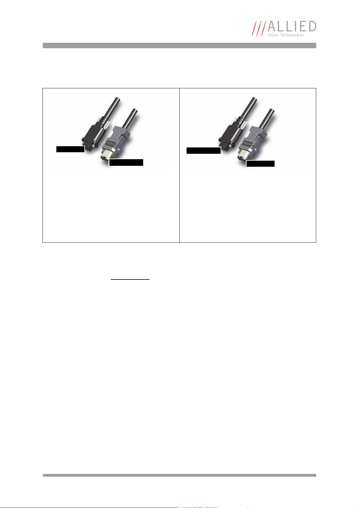
FireWire
1394b port
1394a camera
1394a port
1394b camera
Compatibility between 1394a and 1394b
1394a camera connected to 1394b bus
The cable explains dual compatibility: This cable
serves to connect an IEEE 1394a camera with its
six-pin connector to a bilingual port (a port which
can talk in a- or b-language) of a 1394b bus.
In this case the b-bus communicates in a-language
and a-speed with the camera achieving
a-performance
Figure 4: 1394a and 1394b cameras and compatibility
www
For suitable cables, see:
http://www.alliedvisiontec.com/emea/products/
accessories.html
Compatibility example
It’s possible to run a 1394a and a 1394b camera on the 1394b bus.
You can e.g. run a PIKE F-032B and a MARLIN F-033B on the same bus:
• PIKE F-032B @ S800 and 120 fps (5120 bytes per cycle, 64% of the
cycle slot)
• MARLIN F-033B @ S400 and 30 fps (1280 bytes, 32% of the cycle slot)
1394b camera connected to 1394a bus
The cable explains dual compatibility: In this case,
the cable connects an IEEE 1394b camera with its
nine-pin connector to a 1394a port.
In this case the b-camera communicates in
a-language with the camera achieving
a-performance
Bus runs at 800 Mbit/s for all devices. Data from Marlin’s port is up-converted
from 400 Mbit/s to 800 Mbit/s by data doubling (padding), still needing 32%
of the cycle slot time. This doubles the bandwidth requirement for this port,
as if the camera were running at 60 fps. Total consumption is thus 5120 +
2560 = 7680 bytes per cycle.
PIKE Technical Manual V5.0.0
35
Page 36

FireWire
Image transfer via 1394a and 1394b
Technical detail 1394a 1394b
Transmission mode Half duplex (both pairs needed)
400 Mbit/s data rate
aka: a-mode, data/strobe (D/S)
mode, legacy mode
Devices Up to 63 devices per network
Number of cameras Up to 16 cameras per network
Number of DMAs 4 to 8 DMAs (parallel) cameras / bus
Real time capability Image has real time priority
Available bandwidth acc. IIDC
(per cycle 125 µs)
Max. image bandwidth 31.25 MByte/s 62.5 MByte/s
Max. total bandwidth ~45 MByte/s ~85 MByte/s
Number of busses Multiple busses per PC
CPU load Almost none for DMA image transfer
Gaps Gaps negatively affect asynchro-
4096 bytes per cycle
~ 1000q @ 400 Mbit/s
For further detail read Chapter Frame rates on page 238.
limit: PCI bus
nous performance of widespread
network (round trip delay),
reducing efficiency
Full duplex (one pair needed)
1 Gbit/s signaling rate, 800
Mbit/s data rate
10b/8b coding (Ethernet), aka:
b-mode (beta mode)
8192 bytes per cycle
~ 2000q @ 800 Mbit/s
(@1 GHz clock rate)
Multiple busses per PC
limit: PCI (Express) bus
No gaps needed, BOSS mode for
parallel arbitration
Table 4: Technical detail comparison: 1394a and 1394b
Note
The bandwidth values refer to the fact:
1 MByte = 1024 kByte
PIKE Technical Manual V5.0.0
36
Page 37

FireWire
1394b bandwidths
According to the 1394b specification on isochronous transfer, the largest
data payload size of 8192 bytes per 125 µs cycle is possible with a bandwidth
of 800 Mbit/s.
For further details read Chapter How does bandwidth affect the frame rate?
on page 270.
Requirements for PC and 1394b
Today’s PCs are equipped with the PCIe bus (PCI Express).
PCIe factor PCIe 1.0 PCIe 2.0 PCIe 3.0
x1 250 MByte/s 500 MByte/s 1000 MByte/s
x2 500 MByte/s 1000 MByte/s 2000 MByte/s
x4 1000 MByte/s 2000 MByte/s 4000 MByte/s
x8 2000 MByte/s 4000 MByte/s 8000 MByte/s
x16 4000 MByte/s 8000 MByte/s 16000 MByte/s
x32 8000 MByte/s 16000 MByte/s 32000 MByte/s
Table 5: Theoretical bandwidth of PCIe (PCI Express)
1394b also requires low latency for data transmission (due to small receiveFIFO). In order to get the most out of your camera-to-PC configuration, we
recommend the following chipsets for your PC:
• For Intel-based desktops, chipset 945 (or higher)
• For non-Intel based desktops (e.g. AMD), PCI Express compatible
chipset
www
For more information:
http://support.intel.com/support/chipsets/#desktop
For multi-camera applications one of the following bus cards is needed:
• PCI ExpressCard with potential 250 MByte/s per lane (up to four supported by chipset) or
PIKE Technical Manual V5.0.0
37
Page 38

FireWire
Caution
Requirements for laptop and 1394b
As mentioned above, 1394b requires low latency for data transmission (small
receive-FIFO). In order to get the most out of your camera-to-laptop configuration, we recommend the following chipset for your laptop:
• For Intel-based laptops, chipset 915 (or higher)
• For non-Intel based laptops (e.g. AMD), PCI Express compatible chipset
Because most laptops have (only) one PC-card interface, it is possible to connect one PIKE camera to your laptop at full speed. Alternatively laptops with
an additional 1394 ExpressCard interface can be used.
As mentioned earlier, it is very important not to exceed an
inrush current of 18 mJoule in 3 ms. (This means that a
device, when powered via 12 V bus power must never draw
more than 1.5 A, even not in the first 3 ms.)
Higher inrush current may damage the physical interface
chip of the camera and/or the phy chip in your PC.
Whereas inrush current is not a problem for one Pike camera,
daisy chaining multiple cameras or supplying bus power via
(optional) HIROSE power out to circuitry with unknown
inrush currents needs careful design considerations to be on
the safe side.
Note
The following cardbus adapter for laptops allows the connection of two
industrial screw locking cables (obtainable at AVT).
Recent developments at Apple (TM) allow the INTEL based
Apple computers (both laptops as well as desktops) to run a
Win-OS. This makes it possible to use AVT 1394 camera technology with the same AVT-SDKs.
PIKE Technical Manual V5.0.0
38
Page 39

FireWire
Figure 5: Cardbus adapter with two screw locks (AVT order number E3000104)
Figure 6: ExpressCard Logo, ExpressCard/54 (SIIG)
PIKE Technical Manual V5.0.0
39
Page 40

FireWire
Figure 7: ExpressCard technology
www
Example1: 1394b bandwidth of PIKE cameras
PIKE model Resolution Frame rate Bandwidth
Pike F-032 B/C VGA 208 fps 62.5 MByte/s
Pike F-100 B/C 1 megapixel 60 fps 57.6 MByte/s
Pike F-145 B/C 1.4 megapixel 30 fps 41.4 MByte/s
Pike F-210 B/C 2.1 megapixel 31 fps 62.5 MByte/s
Pike F-421 B/C 4 megapixel 15 fps 62.5 MByte/s
Pike F-505 B/C 5 megapixel 13 fps 62.5 MByte/s
Pike F-1100 B/C 10.7 megapixel 2.6 fps (single-tap)
Pike F-1600 B/C 15.8 megapixel 1.7 fps (single-tap)
ExpressCard is a new standard set by PCMCIA.
For more information visit:
http://www.expresscard.org/web/site/
26.6 MByte/s
4.9 fps (dual-tap)
50.0 MByte/s
25.7 MByte/s
3.1 fps (dual-tap)
Table 6: Bandwidth of Pike cameras
46.8 MByte/s
PIKE Technical Manual V5.0.0
40
Page 41

FireWire
Note
All data are calculated using Raw8 / Mono8 color mode.
Higher bit depths or color modes will double or triple bandwidth requirements.
Example 2: More than one PIKE camera at full speed
Due to the fact that one Pike camera can, depending on its settings, saturate
a 32-bit PCI bus, you are advised to use either a PCI Express card and/or multiple 64-bit PCI bus cards, if you want to use 2 or more Pike cameras simultaneously (see the following table).
# cameras PC hardware required
1 Pike camera at full speed 1 x 32-bit PCI bus card (85 MByte/s)
2 or more Pike cameras at full speed PCI Express card and/or
Multiple 64-bit PCI bus cards
Table 7: Required hardware for multiple camera applications
PIKE Technical Manual V5.0.0
41
Page 42

FireWire
FireWire Plug & play capabilities
FireWire devices implement the ISO/IEC 13213 configuration ROM model for
device configuration and identification, to provide plug & play capability. All
FireWire devices are identified by an IEEE EUI-64 unique identifier (an extension of the 48-bit Ethernet MAC address format) in addition to well-known
codes indicating the type of device and protocols it supports. For further
details read Chapter Configuration of the camera on page 274.
FireWire hot-plug and screw-lock precautions
Caution
Hot-plug precautions
• Although FireWire devices can theoretically be hotplugged without powering down equipment, we
strongly recommend turning the computer power off,
before connecting a digital camera to it via a FireWire
cable.
• Static electricity or slight plug misalignment during
insertion may short-circuit and damage components.
• The physical ports may be damaged by excessive ESD
(electrostatic discharge), when connected under powered conditions. It is good practice to ensure proper
grounding of computer case and camera case to the
same ground potential, before plugging the camera
cable into the port of the computer. This ensures that
no excessive difference of electrical potential exists
between computer and camera.
•It is very important not to exceed the inrush energy of
18 mJoule in 3 ms. (This means that a device, when
powered via 12 V bus power must never draw more than
1.5 A, but only 0.5 A in the first 3 ms, assuming constant flow of current.)
• Higher inrush current may damage the physical
interface chip of the camera and/or the phy chip in
your PC. Whereas inrush current is not a problem for
one Pike camera, daisy chaining multiple cameras or
supplying bus power via (optional) HIROSE power out to
circuitry with unknown inrush currents needs careful
design considerations to be on the safe side.
PIKE Technical Manual V5.0.0
42
Page 43

FireWire
Screw-lock and power supply precautions
Caution
Screw-lock precautions
• Also, all AVT 1394b camera and cables have industrial
screw-lock fasteners, to insure a tight electrical con-
nection that is resistant to vibration and gravity.
• We strongly recommend using only 1394b adapter
cards with screw-locks.
Power supply precautions
• Make sure not to touch the shield of the camera cable
connected to a computer and the ground terminal of the
lines at the same time.
• If you are charged: before touching the shield of the
camera cable, make sure to discharge first (by touching
the ground terminal of the lines).
• Use only DC power supplies with insulated cases. These
are identified by having only two power connectors.
• If you feel uncomfortable with the previous advice or if
you have no knowledge about the connectivity of an
installation, we strongly recommend powering down
all systems before connecting or disconnecting a
camera.
PIKE Technical Manual V5.0.0
43
Page 44

FireWire
Operating system support
Operating system 1394a 1394b
Linux Full support Full support
Apple Mac OS X Full support Full support
Windows XP With SP2 / SP3 the default speed for 1394b is S100 (100 Mbit/s). A
download and registry modification is available from Microsoft to
restore performance to either S400 or S800.
http://support.microsoft.com/kb/885222
Alternatively use the drivers of SP1 instead.
We strongly recommend to install AVT FirePackage, which replaces
the Microsoft driver. (See AVT FirePackage User Guide for details.)
Windows Vista Full support from beginning Vista incl. SP1/SP2 supports
1394b only with S400.
Use either the driver of the AVT
Universal Package or install the
driver provided with the AVT
1394 Bus Driver Package. Both
drivers replace the Microsoft
OHCI IEEE 1394 driver, but the
second is 100% compliant to the
driver of Microsoft. This means,
applications using the MS1394
driver will continue to work.
Windows 7 Full support Full support
Table 8: FireWire and operating systems
www
For more information see AVT Software Selector Guide:
http://www.alliedvisiontec.com/emea/support/downloads/
software.html
PIKE Technical Manual V5.0.0
44
Page 45

Filter and lenses
Filter and lenses
IR cut filter: spectral transmission
The following illustration shows the spectral transmission of the IR cut filter:
Figure 8: Spectral transmission of Jenofilt 217
PIKE Technical Manual V5.0.0
45
Page 46

Filter and lenses
Camera lenses
AVT offers different lenses from a variety of manufacturers. The following
table lists selected image formats depending on camera type, distance and
the focal length of the lens.
Note
All values listed in the following tables are theoretical and
therefore only approximate values (focal length and field of
view).
Focal length
for type 1/3 sensors
PIKE F-032
4.8 mm 0.38 m x 0.5 m 0.75 m x 1 m
8 mm 0.22 m x 0.29 m 0.44 m x 0.58 m
12 mm 0.15 m x 0.19 m 0.29 m x 0.38 m
16 mm 11 cm x 15 cm 22 cm x 29 cm
25 mm 6.9 cm x 9.2 cm 14 cm x 18 cm
35 mm 4.8 cm x 6.4 cm 9.6 cm x 13 cm
50 mm 3.3 cm x 4.4 cm 6.6 cm x 8.8 cm
Table 9: Focal length vs. field of view (PIKE F-032)
Distance = 0.5 m Distance = 1 m
Focal length
for type 2/3 sensors
PIKE F-100/F-145/F-505
4.8 mm 0.7 m x 0.9 m 1.4 m x 1.9 m
8 mm 0.4 m x 0.5 m 0.8 m x 1.1 m
12 mm 0.27 m x 0.36 m 0.54 m x 0.72 m
16 mm 0.2 m x 0.27 m 0.4 m x 0.54 m
25 mm 13 cm x 17 cm 26 cm x 34 cm
35 mm 8.8 cm x 12 cm 18 cm x 24 cm
50 mm 6 cm x 7.9 cm 12 cm x 17 cm
Table 10: Focal length vs. field of view (PIKE F-100/F-145/F-505)
Distance = 0.5 m Distance = 1 m
PIKE Technical Manual V5.0.0
46
Page 47

Filter and lenses
Focal length
for type 1 sensors
PIKE F-210
8 mm 0.6 m x 0.8 m 1.2 m x 1.6 m
12 mm 0.39 m x 0.52 m 0.78 m x 1.2 m
16 mm 0.29 m x 0.38 m 0.58 m x 0.76 m
25 mm 18 cm x 24 cm 36 cm x 49 cm
35 mm 13 cm x 17 cm 26 cm x 34 cm
50 mm 8.8 cm x 12 cm 18 cm x 23 cm
Table 11: Focal length vs. field of view (PIKE F-210)
Note
Focal length
for type 1.2 sensors
PIKE F-421
Distance = 0.5 m Distance = 1 m
Lenses with focal lengths < 35 mm will very likely show excessive shading in the edges of the image due to the fact that
the image size of the sensor is slightly bigger than the
C-mount itself and due to microlenses on the sensor's pixel.
Ask your dealer if you require non C-Mount lenses.
Distance = 0.5 m Distance = 1 m
35 mm 20 cm x 20 cm 42 cm x 42 cm
50 mm 14 cm x 14 cm 29 cm x 29 cm
Table 12: Focal length vs. field of view (PIKE F-421)
Focal length
for type 35 mm sensors
PIKE F-1100/F-1600
18 mm 64 cm x 96 cm 1.3 m x 2.0 m
21 mm 55 cm x 82cm 1.1 m x 1.7 m
25 mm 46 cm x 68 cm 0.94 m x 1.4 m
28 mm 41 cm x 61 cm 0.83 m x 1.3 m
35 mm 32 cm x 48 cm 66 cm x 99 cm
50 mm 22 cm x 32 cm 46 cm x 68 cm
90 mm 11 cm x 16 cm 24 cm x 36 cm
Table 13: Focal length vs. field of view (PIKE F-1100/F-1600)
Distance = 0.5 m Distance = 1 m
PIKE Technical Manual V5.0.0
47
Page 48

Camera dimensions
Camera dimensions
Note
For information on sensor position accuracy:
(sensor shift x/y, optical back focal length z and sensor rotation ) see Chapter Sensor position accuracy of AVT cameras
on page 361.
Serial numbers for starting new front flange
Camera model E-number Starting ...
Pike F-421B E0000882 ... from SN: 09/16-269066321
Pike F-505B E0001141 ... from SN: 09/16-269066246
Table 14: Starting serial numbers for new front flange
PIKE Technical Manual V5.0.0
48
Page 49

Camera dimensions
Note: different from GOF version
see next page
Body size: 96.8 mm x 44 mm x 44 mm (L x W x H)
Mass: 250 g (without lens)
PIKE standard housing (2 x 1394b copper)
Figure 9: Camera dimensions (2 x 1394b copper)
PIKE Technical Manual V5.0.0
49
Page 50

Camera dimensions
Body size: 96.8 mm x 44 mm x 44 mm (L x W x H)
Mass: 250 g (without lens)
Note: different from 2 x copper version
see previous page
PIKE (1394b: 1 x GOF, 1 x copper)
Figure 10: Camera dimensions (1394b: 1 x GOF, 1 x copper)
PIKE Technical Manual V5.0.0
50
Page 51

Camera dimensions
Tripod adapter
This tripod adapter is only designed for standard housings, but not for the
angled head versions.
Note
If you need a tripod adapter for angled head versions,
please contact Customer Care. See Chapter Contacting
Allied Vision Technologies on page 11.
Tripods for F-Mount and M42-Mount (both for Pike F-1100
and F-1600):
see Chapter Pike F-Mount: Tripod adapter on page 66 and
Chapter Pike F-Mount: Tripod adapter on page 66.
Figure 11: Tripod dimensions
PIKE Technical Manual V5.0.0
51
Page 52

Camera dimensions
Pike W90 (2 x 1394b copper)
This version has the sensor tilted by 90 degrees clockwise, so that it views
upwards.
Figure 12: Pike W90 (2 x 1394b copper)
PIKE Technical Manual V5.0.0
52
Page 53

Camera dimensions
Pike W90 (1394b: 1 x GOF, 1 x copper)
This version has the sensor tilted by 90 degrees clockwise, so that it views
upwards.
Figure 13: Pike W90 (1394b: 1 x GOF, 1 x copper)
PIKE Technical Manual V5.0.0
53
Page 54

Camera dimensions
Pike W90 S90 (2 x 1394b copper)
This version has the sensor tilted by 90 degrees clockwise, so that it views
upwards.
The sensor is also rotated by 90 degrees clockwise.
Figure 14: Pike W90 S90 (2 x 1394b copper)
PIKE Technical Manual V5.0.0
54
Page 55

Camera dimensions
Pike W90 S90 (1394b: 1 x GOF, 1 x copper)
This version has the sensor tilted by 90 degrees clockwise, so that it views
upwards.
The sensor is also rotated by 90 degrees clockwise.
Figure 15: Pike W90 S90 (1394b: 1 x GOF, 1 x copper)
PIKE Technical Manual V5.0.0
55
Page 56

Camera dimensions
Pike W270 (2 x 1394b copper)
This version has the sensor tilted by 270 degrees clockwise, so that it views
downwards.
Figure 16: Pike W270 (2 x 1394b copper)
PIKE Technical Manual V5.0.0
56
Page 57

Camera dimensions
Pike W270 (1394b: 1 x GOF, 1 x copper)
This version has the sensor tilted by 270 degrees clockwise, so that it views
downwards.
Figure 17: Pike W270 (1394b: 1 x GOF, 1 x copper)
PIKE Technical Manual V5.0.0
57
Page 58

Camera dimensions
Pike W270 S90 (2 x 1394b copper)
This version has the sensor tilted by 270 degrees clockwise, so that it views
downwards.
The sensor is also rotated by 90 degrees clockwise.
Figure 18: Pike W270 S90 (2 x 1394b copper)
PIKE Technical Manual V5.0.0
58
Page 59
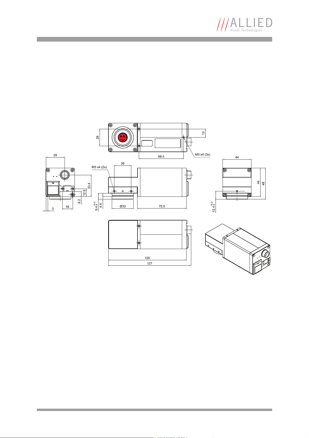
Camera dimensions
Pike W270 S90 (1394b: 1 x GOF, 1 x copper)
This version has the sensor tilted by 270 degrees clockwise, so that it views
downwards.
The sensor is also rotated by 90 degrees clockwise.
Figure 19: Pike W270 S90 (1394b: 1 x GOF, 1 x copper)
PIKE Technical Manual V5.0.0
59
Page 60

Camera dimensions
Cross section: CS-Mount (only PIKE F-032B/C)
Figure 20: Pike CS-Mount dimensions (only PIKE F-032B/C)
PIKE Technical Manual V5.0.0
60
Page 61

Camera dimensions
Cross section: C-Mount (VGA size filter)
PIKE F-032/100/145/505 cameras are equipped with VGA size filter.
Figure 21: Pike C-Mount dimensions (VGA size filter)
PIKE Technical Manual V5.0.0
61
Page 62

Camera dimensions
Cross section: C-Mount (large filter)
PIKE F-210/421 are equipped with a large filter.
Figure 22: Pike C-Mount dimensions (large filter)
PIKE Technical Manual V5.0.0
62
Page 63

Camera dimensions
loosen both screws on top and the right side of the camera
Adjustment of C-Mount
PIKE cameras allow the precise adjustment of the back focus of the C-Mount
by means of a back focus ring which is threaded into the C-Mount and held
by two screws: one on the top (middle) and one on the right side of the camera. The mechanical adjustment of the imaging device is important in order
to achieve a perfect alignment with the focal point of the lens.
Individual adjustment may be required:
• if you cannot focus correctly at near or far distances or
• if the back focal plane of your lens does not conform to the C-Mount
back-focus specification or
• if you have e.g. removed the IR cut filter.
Figure 23: Back focus adjustment
Do the following:
1. Looking in front of the lens loosen both screws on the top (middle) and
the right side of the housing (locations as shown above by arrows) with
an Allen key (1.3 x 50; Order#: K 9020411). If one of this screws is not
available (angled head models W90/W270 S90), use the screw on the
other side.
2. With the lens set to infinity or a known focus distance, set the camera
to view an object located at infinity or the known distance.
3. Rotate the C-Mount ring and lens forward or backwards on its thread
until the object is in sharp focus. Be careful that the lens remains
seated in the C-Mount.
4. Once focus is achieved, tighten the two locking screws without applying
excessive torque.
PIKE Technical Manual V5.0.0
63
Page 64

Camera dimensions
Adjustment of F-Mount for Pike F-1100 and Pike F-1600
Different from the other Pike cameras Pike: F-1100/F-1600 have built-in filter
that cannot be removed.
The dimensional adjustment cannot be done by the customer. All adjustments have to be done by the AVT factory.
If you need any adjustments, please contact Customer Care: For phone
numbers and e-mail: See Chapter Contacting Allied Vision Technologies on
page 11.
F-Mount
For Pike F-1100 and Pike F-1600 the following mounts will be available:
• F-Mount (standard)
• M42-Mount (optional)
• M58-Mount (optional)
Note
For Pike F-1100 and Pike F-1600:
• No K-Mount available.
• No M39-Mount available.
PIKE Technical Manual V5.0.0
64
Page 65

Camera dimensions
29
3
3
.
4
16 6
1
2
.
5
8
M3x3 (4x)
34.5 * 102
136.5
142.8
39.5 *
2
6
M3x3 (4x)
68.5
3
5
3
3
M4x4 (8x)
59
5
9
3
3
* depending on filter
1
5
8
Ø
F-Mount
Pike F-Mount: standard housing
(2 x 1394b copper)
Figure 24: F-Mount Pike standard housing (2 x 1394b copper)
PIKE Technical Manual V5.0.0
65
Page 66

Camera dimensions
Pike F-Mount: Tripod adapter
This tripod adapter is designed for Pike F-Mount/M42-Mount/M58-Mount
standard housings.
74.5
68.5
M6, 6 mm thread depth (2x)
6
2
2
2
54.5
5
Tripod-Adapter
74.5 x 32 x 10 (L x W x H)
UNC 1/4-20, 6 mm thread depth
2
3
6
1
0
1
Figure 25: Tripod dimensions
PIKE Technical Manual V5.0.0
66
Page 67

Camera dimensions
* depending on filter
29
3
3
.
4
8
1
2
.
5
16 6
M3x3 (4x)
68.5
2
6
M3x3 (4x)
35
75.5
3
5
*
137.5
5
9
62
33
4
0
*
M4x4 (8x)
6
4
1
144.2
F-Mount
58Ø
Pike F-Mount: W270 (2 x 1394b copper)
This version has the sensor tilted by 270 degrees clockwise, so that it views
downwards.
Figure 26: F-Mount Pike W270 (2 x 1394b copper)
PIKE Technical Manual V5.0.0
67
Page 68

Camera dimensions
F-Mount
Adjustment spacer
Ø
4
7
maximum
protrusion:
26
filter / protection glass
Cross section: F-Mount
Figure 27: Pike F-Mount dimensions (standard for Pike F-1100 and Pike F-1600)
PIKE Technical Manual V5.0.0
68
Page 69

Camera dimensions
K-Mount, M39-Mount
Note
For other mounts (e.g. K-Mount, M39-Mount) please contact
your distributor.
Note
Cross section: M39-Mount
Pike F-210 and Pike F-421 can be equipped at factory site
with M39-Mount instead of C-Mount.
M39-Mount is ideally suited for Voigtländer (aka Voigtlander)
short focal length optics. See drawing below for further
details.
Please ask AVT or your local dealer if you require further information.
Figure 28: Pike M39-Mount dimensions (only Pike F-210 and Pike F-421)
PIKE Technical Manual V5.0.0
69
Page 70
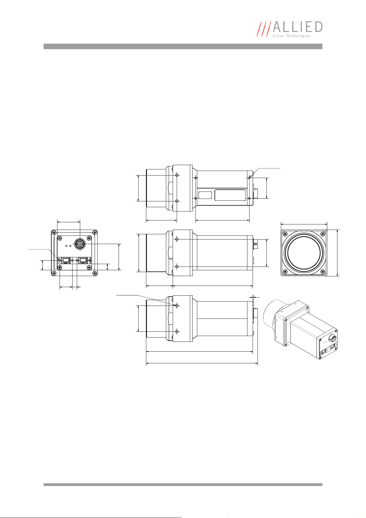
Camera dimensions
29
3
3
.
4
16 6
1
2
.
5
8
M3x3 (4x)
34 * 102
136
142.3
39 *
2
6
M3x3 (4x)
68.5
3
5
3
3
M4x4 (8x)
59
5
9
3
3
* depending on filter
1
n
4
8
M42-Mount
Pike F-1100 and Pike F-1600 cameras can optionally be ordered with M42Mount.
Pike M42-Mount: standard housing
(2 x 1394b copper)
Figure 29: M42-Mount Pike standard housing (2 x 1394b copper)
PIKE Technical Manual V5.0.0
70
Page 71

Camera dimensions
Pike M42-Mount: Tripod adapter
This tripod adapter is designed for Pike F-Mount/M42-Mount/M58-Mount
standard housings.
74.5
68.5
M6, 6 mm thread depth (2x)
6
2
2
2
54.5
5
Tripod-Adapter
74.5 x 32 x 10 (L x W x H)
UNC 1/4-20, 6 mm thread depth
2
3
6
1
0
1
Figure 30: Tripod dimensions
PIKE Technical Manual V5.0.0
71
Page 72

Camera dimensions
* depending on filter
29
3
3
.
4
8
1
2
.
5
16 6
M3x3 (4x)
68.5
2
6
M3x3 (4x)
35
75.5
3
4
.
5
*
137.5
5
9
62
33
3
9
.
5
*
M4x4 (8x)
6
3
.
5
1
144.2
M42x1
Pike M42-Mount: W270 (2 x 1394b copper)
This version has the sensor tilted by 270 degrees clockwise, so that it views
downwards.
Figure 31: M42-Mount Pike W270 (2 x 1394b copper)
PIKE Technical Manual V5.0.0
72
Page 73

Camera dimensions
45.7
maximum
protrusion:
28
filter / protection glass
Adjustment spacer
M
4
2
x
1
Cross section: M42-Mount
Figure 32: Pike M42-Mount dimensions (optional for Pike F-1100 and Pike F-1600)
PIKE Technical Manual V5.0.0
73
Page 74

Camera dimensions
29
3
3
.
4
16 6
1
2
.
5
8
M3x3 (4x)
8.5 *
102
110.5
116.8
13.5 *
2
6
M3x3 (4x)
68.5
3
5
3
3
M4x4 (8x)
59
5
9
3
3
* depending on filter
1
M58x0.75
M58-Mount
Pike F-1100 and Pike F-1600 cameras can optionally be ordered with M58Mount.
Pike M58-Mount: standard housing
(2 x 1394b copper)
Figure 33: M58-Mount Pike standard housing (2 x 1394b copper)
PIKE Technical Manual V5.0.0
74
Page 75

Camera dimensions
Pike M58-Mount: Tripod adapter
This tripod adapter is designed for Pike F-Mount/M42-Mount/M58-Mount
standard housings.
74.5
68.5
M6, 6 mm thread depth (2x)
6
2
2
2
54.5
5
Tripod-Adapter
74.5 x 32 x 10 (L x W x H)
UNC 1/4-20, 6 mm thread depth
2
3
6
1
0
1
Figure 34: Tripod dimensions
PIKE Technical Manual V5.0.0
75
Page 76

Camera dimensions
* depending on filter
29
3
3
.
4
8
1
2
.
5
16 6
M3x3 (4x)
68.5
2
6
M3x3 (4x)
35
75.5
9
*
137.5
5
9
62
33
1
4
*
M4x4 (8x)
3
8
1
144.2
M58x0.75
Pike M58-Mount: W270 (2 x 1394b copper)
This version has the sensor tilted by 270 degrees clockwise, so that it views
downwards.
Figure 35: M58-Mount Pike W270 (2 x 1394b copper)
PIKE Technical Manual V5.0.0
76
Page 77

Camera dimensions
20.5
Adjustment spacer
filter / protection glass
n
4
6
.
4
8
maximum
protrusion:
Cross section: M58-Mount
Figure 36: Pike M42-Mount dimensions (optional for Pike F-1100 and Pike F-1600)
PIKE Technical Manual V5.0.0
77
Page 78

Specifications
Specifications
PIKE F-032B/C (fiber)
Feature Specification
Image device Type 1/3 (diag. 5.92 mm) type progressive scan KODAK IT CCD
KAI340A/C with HAD microlens
Effective chip size 4.7 mm x 3.6 mm
Cell size 7.4 µm x 7.4 µm
Picture size (max.) 640 x 480 pixels (Format_7 Mode_0)
Lens mount Adjustable C-Mount: 17.526 mm (in air); Ø 25.4 mm (32 tpi)
mechanical flange back to filter distance: 12.5 mm
(see Figure 21: Pike C-Mount dimensions (VGA size filter) on page
61)
Adjustable CS-Mount: 12.526 mm (in air), Ø 25.4 mm (32 tpi),
mechanical flange back distance: 7.9 mm
(see Figure 20: Pike CS-Mount dimensions (only PIKE F-032B/C) on
page 60)
ADC 14 bit
Color modes Only color: Raw8, Raw12, Raw16, Mono8, YUV422, YUV411, RGB8
Frame rates 1.875 fps; 3.75 fps; 7.5 fps; 15 fps; 30 fps; 60 fps; 120 fps
up to 208 fps in Format_7 (Mono8)
Gain control Manual: 0-22 dB (0.0353 dB/step); auto gain (select. AOI)
Shutter speed 18 µs … 67,108,864 µs (~67s); auto shutter (select. AOI)
External trigger shutter Programmable, trigger level control, single trigger,
bulk trigger, programmable trigger delay
Internal FIFO memory Up to 105 frames
Look-up tables 16 user-defined (14 bit 14 bit); gamma (0.45 and 0.7)
Smart functions AGC (auto gain control), AEC (auto exposure control), real-time
shading correction, LUT, 64 MByte image memory, mirror, binning,
sub-sampling, High SNR, storable user sets
only color: AWB (auto white balance), color correction, hue, saturation, sharpness
Two configurable inputs, four configurable outputs
RS-232 port (serial port, IIDC V1.31)
Transfer rate 100 Mbit/s, 200 Mbit/s, 400 Mbit/s, 800 Mbit/s
Table 15: Specification PIKE F-032B/C (fiber)
PIKE Technical Manual V5.0.0
78
Page 79

Specifications
Feature Specification
Digital interface IEEE 1394b (IIDC V1.31), 2 x copper connectors (bilingual) (daisy
chain)
fiber: IEEE 1394b, 2 connectors: 1 x copper (bilingual), 1 x GOF
connector (2 x optical fiber on LCLC), (daisy chain)
Power requirements DC 8 V - 36 V via IEEE 1394 cable or 12-pin HIROSE
Power consumption Typical 5 watt (@ 12 V DC); fiber: typical 5.75 watt (@ 12 V DC)
(full resolution and maximal frame rates)
Dimensions 96.8 mm x 44 mm x 44 mm (L x W x H); incl. connectors, without
tripod and lens
Mass 250 g (without lens)
Operating temperature + 5 °C ... + 50 °C housing temperature (without condensation)
Storage temperature - 10 °C ... + 70 °C ambient temperature (without condensation)
Regulations CE, FCC Class B, RoHS (2002/95/EC)
Standard accessories b/w: protection glass
color: IR cut filter
Optional accessories b/w: IR cut filter, IR pass filter
color: protection glass
On request Host adapter card, angled head, power out (HIROSE)
Software packages Various SDKs with interfaces to ActiveX, DirectShow or Twain (free
charge)
Table 15: Specification PIKE F-032B/C (fiber)
Note
The design and specifications for the products described
above may change without notice.
PIKE Technical Manual V5.0.0
79
Page 80

Specifications
PIKE F-100B/C (fiber)
Feature Specification
Image device Type 2/3 (diag. 10.5 mm) type progressive scan KODAK IT CCD
KAI1020A/C with HAD microlens
Effective chip size 7.4 mm x 7.4 mm
Cell size 7.4 µm x 7.4 µm
Picture size (max.) 1000 x 1000 pixels (Format_7 Mode_0)
Lens mount Adjustable C-Mount: 17.526 mm (in air); Ø 25.4 mm (32 tpi)
mechanical flange back to filter distance: 12.5 mm
(see Figure 22: Pike C-Mount dimensions (large filter) on page 62)
ADC 14 bit
Color modes Only color: Raw8, Raw12, Raw16, Mono8, YUV422, YUV411, RGB8
Frame rates 1.875 fps; 3.75 fps; 7.5 fps; 15 fps; 30 fps; 60 fps
up to 60 fps in Format_7 (Mono8)
Gain control Manual: 0-22 dB (0.0353 dB/step); auto gain (select. AOI)
Shutter speed 43 µs … 67,108,864 µs (~67s); auto shutter (select. AOI)
External trigger shutter Programmable, trigger level control, single trigger,
bulk trigger, programmable trigger delay
Internal FIFO memory Up to 32 frames
Look-up tables 16 user-defined (14 bit 14 bit); gamma (0.45 and 0.7)
Smart functions AGC (auto gain control), AEC (auto exposure control), real-time
shading correction, LUT, 64 MByte image memory, mirror, binning,
sub-sampling, High SNR, storable user sets
only color: AWB (auto white balance), color correction, hue, saturation, sharpness
Two configurable inputs, four configurable outputs
RS-232 port (serial port, IIDC V1.31)
Transfer rate 100 Mbit/s, 200 Mbit/s, 400 Mbit/s, 800 Mbit/s
Digital interface IEEE 1394b (IIDC V1.31), 2 x copper connectors (bilingual) (daisy
chain)
fiber: IEEE 1394b, 2 connectors: 1 x copper (bilingual), 1 x GOF
connector (2 x optical fiber on LCLC), (daisy chain)
Power requirements DC 8 V - 36 V via IEEE 1394 cable or 12-pin HIROSE
Power consumption Typical 5 watt (@ 12 V DC); fiber: typical 5.75 watt (@ 12 V DC)
Dimensions 96.8 mm x 44 mm x 44 mm (L x W x H); incl. connectors, without
tripod and lens
Mass 250 g (without lens)
Table 16: Specification PIKE F-100B/C (fiber)
PIKE Technical Manual V5.0.0
80
Page 81

Specifications
Feature Specification
Operating temperature + 5 °C ... + 50 °C housing temperature (without condensation)
Storage temperature - 10 °C ... + 70 °C ambient temperature (without condensation)
Regulations CE, FCC Class B, RoHS (2002/95/EC)
Standard accessories b/w: protection glass
color: IR cut filter
Optional accessories b/w: IR cut filter, IR pass filter
color: protection glass
On request Host adapter card, angled head, power out (HIROSE)
Software packages Various SDKs with interfaces to ActiveX, DirectShow or Twain (free
charge)
Table 16: Specification PIKE F-100B/C (fiber)
Note
The design and specifications for the products described
above may change without notice.
PIKE Technical Manual V5.0.0
81
Page 82

Specifications
PIKE F-145B/C (fiber) (-15fps*)
* Variant: F-145-15fps only
This variant offers lower speed (only 15 fps), but better image quality.
Feature Specification
Image device Type 2/3 (diag. 11.2 mm) type progressive scan SONY ICX285AL/AQ
with EXview HAD microlens
Effective chip size 9.0 mm x 6.7 mm
Cell size 6.45 µm x 6.45 µm
Picture size (max.) 1388 x 1038 pixels (Format_7 Mode_0)
Lens mount Adjustable C-Mount: 17.526 mm (in air); Ø 25.4 mm (32 tpi)
mechanical flange back to filter distance: 12.5 mm
(see Figure 22: Pike C-Mount dimensions (large filter) on page 62)
ADC 14 bit
Color modes Only color: Raw8, Raw12, Raw16, Mono8, YUV422, YUV411, RGB8
Frame rates 1.875 fps; 3.75 fps; 7.5 fps; 15 fps; 30 fps (* Variant: F-145-15fps
only up to 15 fps)
up to 30 (16*) fps in Format_7 (Mono8/12 no sub-sampling)
Gain control Manual: 0-32 dB (0.0358 dB/step); auto gain (select. AOI)
Shutter speed 39 (71*) µs … 67,108,864 µs (~67s); auto shutter (select. AOI)
External trigger shutter Programmable, trigger level control, single trigger,
bulk trigger, programmable trigger delay
Internal FIFO memory Up to 22 frames
Look-up tables 16 user-defined (14 bit 14 bit); gamma (0.45 and 0.7)
Smart functions AGC (auto gain control), AEC (auto exposure control), real-time
shading correction, LUT, 64 MByte image memory, mirror, binning,
sub-sampling, High SNR, storable user sets
only color: AWB (auto white balance), color correction, hue, saturation, sharpness
Two configurable inputs, four configurable outputs
RS-232 port (serial port, IIDC V1.31)
Transfer rate 100 Mbit/s, 200 Mbit/s, 400 Mbit/s, 800 Mbit/s
Digital interface IEEE 1394b (IIDC V1.31), 2 x copper connectors (bilingual) (daisy
chain)
fiber: IEEE 1394b, 2 connectors: 1 x copper (bilingual), 1 x GOF
connector (2 x optical fiber on LCLC), (daisy chain)
Power requirements DC 8 V - 36 V via IEEE 1394 cable or 12-pin HIROSE
Power consumption Typical 5 watt (@ 12 V DC); fiber: typical 5.75 watt (@ 12 V DC)
Table 17: Specification PIKE F-145B/C (fiber)
PIKE Technical Manual V5.0.0
82
Page 83

Specifications
Feature Specification
Dimensions 96.8 mm x 44 mm x 44 mm (L x W x H); incl. connectors, without
tripod and lens
Mass 250 g (without lens)
Operating temperature + 5 °C ... + 50 °C housing temperature (without condensation)
Storage temperature - 10 °C ... + 70 °C ambient temperature (without condensation)
Regulations CE, FCC Class B, RoHS (2002/95/EC)
Standard accessories b/w: protection glass
color: IR cut filter
Optional accessories b/w: IR cut filter, IR pass filter
color: protection glass
On request Host adapter card, angled head, power out (HIROSE)
Software packages Various SDKs with interfaces to ActiveX, DirectShow or Twain (free
charge)
Table 17: Specification PIKE F-145B/C (fiber)
Note
The design and specifications for the products described
above may change without notice.
PIKE Technical Manual V5.0.0
83
Page 84

Specifications
PIKE F-210B/C (fiber)
Feature Specification
Image device Type 1 (diag. 16.3 mm) type progressive scan KODAK IT CCD
KAI2093A/C with HAD microlens
Effective chip size 14 mm x 8.0 mm
Cell size 7.4 µm x 7.4 µm
Picture size (max.) 1920 x 1080 pixels (Format_7 Mode_0)
Lens mount Adjustable C-Mount: 17.526 mm (in air); Ø 25.4 mm (32 tpi)
mechanical flange back to filter distance: 12.5 mm
(see Figure 22: Pike C-Mount dimensions (large filter) on page 62)
ADC 14 bit
Color modes Only color: Raw8, Raw12, Raw16, Mono8, YUV422, YUV411, RGB8
Frame rates 1.875 fps; 3.75 fps; 7.5 fps; 15 fps; 30 fps
up to 31 fps in Format_7 (Mono8, no sub-sampling)
Gain control Manual: 0-22 dB (0.0353 dB/step); auto gain (select. AOI)
Shutter speed 43 µs … 67,108,864 µs (~67s); auto shutter (select. AOI)
External Trigger Shutter Programmable, trigger level control, single trigger,
bulk trigger, programmable trigger delay
Internal FIFO memory Up to 15 frames
Look-up tables 16 user-defined (14 bit 14 bit); gamma (0.45 and 0.7)
Smart functions AGC (auto gain control), AEC (auto exposure control), real-time
shading correction, LUT, 64 MByte image memory, mirror, binning,
sub-sampling, High SNR, storable user sets
only color: AWB (auto white balance), color correction, hue, saturation, sharpness
Two configurable inputs, four configurable outputs
RS-232 port (serial port, IIDC V1.31)
Transfer rate 100 Mbit/s, 200 Mbit/s, 400 Mbit/s, 800 Mbit/s
Digital interface IEEE 1394b (IIDC V1.31), 2 x copper connectors (bilingual) (daisy
chain)
fiber: IEEE 1394b, 2 connectors: 1 x copper (bilingual), 1 x GOF
connector (2 x optical fiber on LCLC), (daisy chain)
Power requirements DC 8 V - 36 V via IEEE 1394 cable or 12-pin HIROSE
Power consumption Typical 5.5 watt (@ 12 V DC); fiber: typical 6.25 watt (@ 12 V DC)
Dimensions 96.8 mm x 44 mm x 44 mm (L x W x H); incl. connectors, without
tripod and lens
Mass 250 g (without lens)
Table 18: Specification PIKE F-210B/C (fiber)
PIKE Technical Manual V5.0.0
84
Page 85

Specifications
Feature Specification
Operating temperature + 5 °C ... + 50 °C housing temperature (without condensation)
Storage temperature - 10 °C ... + 70 °C ambient temperature (without condensation)
Regulations CE, FCC Class B, RoHS (2002/95/EC)
Standard accessories b/w: protection glass
color: IR cut filter
Optional accessories b/w: IR cut filter, IR pass filter
color: protection glass
On request Host adapter card, angled head, power out (HIROSE)
M39-Mount suitable for e.g. Voigtländer optics
Adjustable M39-Mount: 28.80 mm (in air); M39 x 26 tpi
mechanical flange back to filter distance: 24.2 mm (see Figure 28:
Pike M39-Mount dimensions (only Pike F-210 and Pike F-421) on
page 69)
Software packages Various SDKs with interfaces to ActiveX, DirectShow or Twain (free
charge)
Table 18: Specification PIKE F-210B/C (fiber)
Note
The design and specifications for the products described
above may change without notice.
PIKE Technical Manual V5.0.0
85
Page 86

Specifications
PIKE F-421B/C (fiber)
Feature Specification
Image device Type 1.2 (diag. 21.4 mm) type progressive scan KODAK IT CCD
KAI4022A/C with HAD microlens
Effective chip size 15 mm x 15 mm
Cell size 7.4 µm x 7.4 µm
Picture size (max.) 2048 x 2048 pixels (Format_7 Mode_0)
Lens mount Adjustable C-Mount: 17.526 mm (in air); Ø 25.4 mm (32 tpi)
mechanical flange back to filter distance: 12.5 mm
(see Figure 22: Pike C-Mount dimensions (large filter) on page 62)
ADC 14 bit
Color modes Only color: Raw8, Raw12, Raw16, Mono8, YUV422, YUV411, RGB8
Frame rates 1.875 fps; 3.75 fps; 7.5 fps; 15 fps; 30 fps
up to 16 fps in Format_7 (Mono8)
Gain control Manual: 0-22 dB (0.0353 dB/step); auto gain (select. AOI)
Shutter speed 70 µs … 67,108,864 µs (~67s); auto shutter (select. AOI)
External trigger shutter Programmable, trigger level control, single trigger,
bulk trigger, programmable trigger delay
Internal FIFO memory Up to 6 frames
Look-up tables 16 user-defined (14 bit 14 bit); gamma (0.45 and 0.7)
Smart functions AGC (auto gain control), AEC (auto exposure control), real-time
shading correction, LUT, 64 MByte image memory, mirror, binning,
sub-sampling, High SNR, storable user sets
only color: AWB (auto white balance), color correction, hue, saturation, sharpness
Two configurable inputs, four configurable outputs
RS-232 port (serial port, IIDC V1.31)
Transfer rate 100 Mbit/s, 200 Mbit/s, 400 Mbit/s, 800 Mbit/s
Digital interface IEEE 1394b (IIDC V1.31), 2 x copper connectors (bilingual) (daisy
chain)
fiber: IEEE 1394b, 2 connectors: 1 x copper (bilingual), 1 x GOF
connector (2 x optical fiber on LCLC), (daisy chain)
Power requirements DC 8 V - 36 V via IEEE 1394 cable or 12-pin HIROSE
Power consumption Typical 5.5 watt (@ 12 V DC); fiber: typical 6.25 watt (@ 12 V DC)
Dimensions 96.8 mm x 44 mm x 44 mm (L x W x H); incl. connectors, without
tripod and lens
Mass 250 g (without lens)
Table 19: Specification PIKE F-421B/C (fiber)
PIKE Technical Manual V5.0.0
86
Page 87

Specifications
Feature Specification
Operating temperature + 5 °C ... + 50 °C housing temperature (without condensation)
Storage temperature - 10 °C ... + 70 °C ambient temperature (without condensation)
Regulations CE, FCC Class B, RoHS (2002/95/EC)
Standard accessories b/w: protection glass
color: IR cut filter
Optional accessories b/w: IR cut filter, IR pass filter
color: protection glass
On request Host adapter card, angled head, power out (HIROSE)
M39-Mount suitable for e.g. Voigtländer optics
Adjustable M39-Mount: 28.80 mm (in air); M39 x 26 tpi
mechanical flange back to filter distance: 24.2 mm (see Figure 28:
Pike M39-Mount dimensions (only Pike F-210 and Pike F-421) on
page 69)
Software packages Various SDKs with interfaces to ActiveX, DirectShow or Twain (free
charge)
Table 19: Specification PIKE F-421B/C (fiber)
Note
The design and specifications for the products described
above may change without notice.
PIKE Technical Manual V5.0.0
87
Page 88

Specifications
PIKE F-505B/C (fiber)
Feature Specification
Image device Type 2/3 (diag. 11.0 mm) progressive scan SONY ICX625ALA/AQA
with Super HAD microlens
Effective chip size 8.5 mm × 7.1 mm
Cell size 3.45 µm x 3.45 µm
Picture size (max.) 2452 x 2054 pixels (Format_7 Mode_0)
Lens mount Adjustable C-Mount: 17.526 mm (in air); Ø 25.4 mm (32 tpi)
mechanical flange back to filter distance: 12.5 mm
(see Figure 22: Pike C-Mount dimensions (large filter) on page 62)
ADC 14 bit
Color modes Only color: Raw8, Raw12, Raw16, Mono8, YUV422, YUV411, RGB8
Frame rates 1.875 fps; 3.75 fps; 7.5 fps; 15 fps
up to 15* fps in Format_7 (Mono8 no sub-sampling)
* at 11000 bytes per packet
Gain control Manual: 0-24 dB (0.0359 dB/step); auto gain (select. AOI)
Shutter speed 27 µs … 67,108,864 µs (~67s); auto shutter (select. AOI)
External trigger shutter Programmable, trigger level control, single trigger,
bulk trigger, programmable trigger delay
Internal FIFO memory Up to 5 frames
Look-up tables 16 user-defined (14 bit 14 bit); gamma (0.45 and 0.7)
Smart functions AGC (auto gain control), AEC (auto exposure control), real-time
shading correction, LUT, 64 MByte image memory, mirror, binning,
sub-sampling, High SNR, storable user sets
only color: AWB (auto white balance), color correction, hue, saturation, sharpness
Two configurable inputs, four configurable outputs
RS-232 port (serial port, IIDC V1.31)
Transfer rate 100 Mbit/s, 200 Mbit/s, 400 Mbit/s, 800 Mbit/s
Digital interface IEEE 1394b (IIDC V1.31), 2 x copper connectors (bilingual) (daisy
chain)
fiber: IEEE 1394b, 2 connectors: 1 x copper (bilingual), 1 x GOF
connector (2 x optical fiber on LCLC), (daisy chain)
Power requirements DC 8 V - 36 V via IEEE 1394 cable or 12-pin HIROSE
Power consumption Typical 5.75 watt (@ 12 V DC); fiber: typical 6.50 watt (@ 12 V DC)
Dimensions 96.8 mm x 44 mm x 44 mm (L x W x H); incl. connectors, without
tripod and lens
Table 20: Specification PIKE F-505B/C (fiber)
PIKE Technical Manual V5.0.0
88
Page 89

Specifications
Feature Specification
Mass 250 g (without lens)
Operating temperature + 5 °C ... + 50 °C housing temperature (without condensation)
Storage temperature - 10 °C ... + 70 °C ambient temperature (without condensation)
Regulations CE, FCC Class B, RoHS (2002/95/EC)
Standard accessories b/w: protection glass
color: IR cut filter
Optional accessories b/w: IR cut filter, IR pass filter
color: protection glass
On request Host adapter card, angled head, power out (HIROSE)
Software packages Various SDKs with interfaces to ActiveX, DirectShow or Twain (free
charge)
Table 20: Specification PIKE F-505B/C (fiber)
Note
The design and specifications for the products described
above may change without notice.
PIKE Technical Manual V5.0.0
89
Page 90

Specifications
PIKE F-1100B/C (fiber)
Feature Specification
Image device Type 35 mm (diag. 43.3 mm) progressive scan KODAK IT CCD
KAI-11002 with Super HAD microlens
Effective chip size 37.25 mm × 25.7 mm
Cell size 9.0 µm x 9.0 µm
Picture size (max.) 4008 x 2672 pixels
Lens mount Standard: F-Mount: 46.5 mm (in air)
maximum protrusion: 26 mm
(see Figure 27: Pike F-Mount dimensions (standard for Pike F-1100
and Pike F-1600) on page 68)
Optional: M42-Mount: 45.5 mm (in air)
maximum protrusion: 28 mm
(Figure 32: Pike M42-Mount dimensions (optional for Pike F-1100
and Pike F-1600) on page 73)
Optional: M58-Mount: 20.5 mm (in air)
maximum protrusion: 8 mm
(Figure 36: Pike M42-Mount dimensions (optional for Pike F-1100
and Pike F-1600) on page 77)
ADC 14 bit
Color modes Only color: Raw8, Raw12, Raw16, Mono8, YUV422, YUV411, RGB8
Frame rates 1.875 fps; 3.75 fps
up to 2.6* fps (single-tap) / up to 4.9* fps (dual-tap) in Format_7
(Mono8 no sub-sampling)
* at 11000 bytes per packet
User can switch between single-tap and dual-tap.
Gain control Manual: 0-24 dB (0.0359 dB/step); auto gain (select. AOI)
Shutter speed 129 µs … 67,108,864 µs (~67s); auto shutter (select. AOI)
External trigger shutter Programmable, trigger level control, single trigger,
bulk trigger, programmable trigger delay
Internal FIFO memory Up to 5 frames
Look-up tables 16 user-defined (14 bit 14 bit); gamma (0.45 and 0.7)
Table 21: Specification PIKE F-1100B/C (fiber)
PIKE Technical Manual V5.0.0
90
Page 91

Specifications
Feature Specification
Smart functions AGC (auto gain control), AEC (auto exposure control), real-time
shading correction, LUT, 256 MByte image memory, mirror, binning,
sub-sampling, High SNR, storable user sets
only color: AWB (auto white balance), color correction, hue, saturation, sharpness
Two configurable inputs, four configurable outputs
RS-232 port (serial port, IIDC V1.31)
Transfer rate 100 Mbit/s, 200 Mbit/s, 400 Mbit/s, 800 Mbit/s
Digital interface IEEE 1394b (IIDC V1.31), 2 x copper connectors (bilingual) (daisy
chain)
fiber: IEEE 1394b, 2 connectors: 1 x copper (bilingual), 1 x GOF
connector (2 x optical fiber on LCLC), (daisy chain)
Power requirements DC 8 V - 36 V via IEEE 1394 cable or 12-pin HIROSE
Power consumption Typical single-tap: 5 watt (@ 12 V DC);
fiber: typical tbd watt (@ 12 V DC)
Typical dual-tap: 5.5 watt (@ 12 V DC);
fiber: typical tbd watt (@ 12 V DC)
Dimensions 142.8 mm x 59 mm x 59 mm (L x W x H); incl. connectors, without
tripod and lens
Mass 380 g (without lens)
Operating temperature + 5 °C ... + 45 °C ambient temperature (without condensation)
Storage temperature - 10 °C ... + 70 °C ambient temperature (without condensation)
Regulations CE, FCC Class B, RoHS (2002/95/EC)
Standard accessories b/w: protection glass
color: IR cut filter
Optional accessories b/w: IR cut filter, IR pass filter
color: protection glass
On request Host adapter card, angled head, power out (HIROSE)
Software packages Various SKDs with interfaces to ActiveX, DirectShow or Twain (free
charge)
Table 21: Specification PIKE F-1100B/C (fiber)
Note
The design and specifications for the products described
above may change without notice.
PIKE Technical Manual V5.0.0
91
Page 92

Specifications
PIKE F-1600B/C (fiber)
Feature Specification
Image device Type 35 mm (diag. 43.3 mm) progressive scan KODAK IT CCD
KAI-16000 with Super HAD microlens
Effective chip size 36.1 mm × 24 mm
Cell size 7.4 µm x 7.4 µm
Picture size (max.) 4872 x 3248 pixels
Lens mount Standard: F-Mount: 46.5 mm (in air)
maximum protrusion: 26 mm
(see Figure 27: Pike F-Mount dimensions (standard for Pike F-1100
and Pike F-1600) on page 68)
Optional: M42-Mount: 45.5 mm (in air)
maximum protrusion: 28 mm
(Figure 32: Pike M42-Mount dimensions (optional for Pike F-1100
and Pike F-1600) on page 73)
Optional: M58-Mount: 20.5 mm (in air)
maximum protrusion: 8 mm
(Figure 36: Pike M42-Mount dimensions (optional for Pike F-1100
and Pike F-1600) on page 77)
ADC 14 bit
Color modes Only color: Raw8, Raw12, Raw16, Mono8, YUV422, YUV411, RGB8
Frame rates 1.875 fps; 3.75 fps; 7.5 fps; 15 fps
up to 1.7* fps (single-tap) / up to 3.1* fps (dual-tap) in Format_7
(Mono8 no sub-sampling)
* at 11000 bytes per packet
User can switch between single-tap and dual-tap.
Gain control Manual: 0-24 dB (0.0359 dB/step); auto gain (select. AOI)
Shutter speed 636 µs … 67,108,864 µs (~67s); auto shutter (select. AOI)
External trigger shutter Programmable, trigger level control, single trigger,
bulk trigger, programmable trigger delay
Internal FIFO memory Up to 5 frames
Look-up tables 16 user-defined (14 bit 14 bit); gamma (0.45 and 0.7)
Table 22: Specification PIKE F-1600B/C (fiber)
PIKE Technical Manual V5.0.0
92
Page 93

Specifications
Feature Specification
Smart functions AGC (auto gain control), AEC (auto exposure control), real-time
shading correction, LUT, 256 MByte image memory, mirror, binning,
sub-sampling, High SNR, storable user sets
only color: AWB (auto white balance), color correction, hue, saturation, sharpness
Two configurable inputs, four configurable outputs
RS-232 port (serial port, IIDC V1.31)
Transfer rate 100 Mbit/s, 200 Mbit/s, 400 Mbit/s, 800 Mbit/s
Digital interface IEEE 1394b (IIDC V1.31), 2 x copper connectors (bilingual) (daisy
chain)
fiber: IEEE 1394b, 2 connectors: 1 x copper (bilingual), 1 x GOF
connector (2 x optical fiber on LCLC), (daisy chain)
Power requirements DC 8 V - 36 V via IEEE 1394 cable or 12-pin HIROSE
Power consumption Typical single-tap: 6.25 watt (@ 12 V DC); fiber: typical tbd watt
(@ 12 V DC)
Typical dual-tap: 6.5 watt (@ 12 V DC); fiber: typical tbd watt (@
12 V DC)
Dimensions 142.8 mm x 59 mm x 59 mm mm (L x W x H); incl. connectors, with-
out tripod and lens
Mass 380 g (without lens)
Operating temperature + 5 °C ... + 45 °C housing temperature (without condensation)
Storage temperature - 10 °C ... + 70 °C ambient temperature (without condensation)
Regulations CE, FCC Class B, RoHS (2002/95/EC)
Standard accessories b/w: protection glass
color: IR cut filter
Optional accessories b/w: IR cut filter, IR pass filter
color: protection glass
On request Host adapter card, angled head, power out (HIROSE)
Software packages Various SKDs with interfaces to ActiveX, DirectShow or Twain (free
charge)
Table 22: Specification PIKE F-1600B/C (fiber)
Note
The design and specifications for the products described
above may change without notice.
PIKE Technical Manual V5.0.0
93
Page 94

Specifications
Spectral sensitivity
Note
All measurements were done without protection glass /
without filter.
The uncertainty in measurement of the QE values is 10%.
This is due to:
• Manufacturing tolerance of the sensor
• Uncertainties in the measuring apparatus itself
(GERMAN: Ulbricht-Kugel / ENGLISH: Ulbricht sphere,
optometer, etc.)
PIKE Technical Manual V5.0.0
94
Page 95

Specifications
Figure 37: Spectral sensitivity of Pike F-032B
Figure 38: Spectral sensitivity of Pike F-032C
PIKE Technical Manual V5.0.0
95
Page 96

Specifications
With clear glass (AR coated), with microlens
0.00
0.05
0.10
0.15
0.20
0.25
0.30
0.35
0.40
0.45
0.50
300 400 500 600 700 800 900
Wavelength (nm)
Absolute Quantum Efficiency
Figure 39: Spectral sensitivity of Pike F-100B
Figure 40: Spectral sensitivity of Pike F-100C
PIKE Technical Manual V5.0.0
96
Page 97

Specifications
Sensor Response
0%
10%
20%
30%
40%
50%
60%
400 500 600 700 800 900 1000 1100
Wavelength [nm]
Quantum Efficiency
Monochrome
Sensor Response
0%
5%
10%
15%
20%
25%
30%
35%
40%
45%
50%
400 450 500 550 600 650 700 750
Wavelength [nm]
Quantum Efficiency
Red Green Blue
Figure 41: Spectral sensitivity of Pike F-145B
Figure 42: Spectral sensitivity of Pike F-145C
PIKE Technical Manual V5.0.0
97
Page 98

Specifications
Figure 43: Spectral sensitivity of Pike F-210B
Figure 44: Spectral sensitivity of Pike F-210C
PIKE Technical Manual V5.0.0
98
Page 99
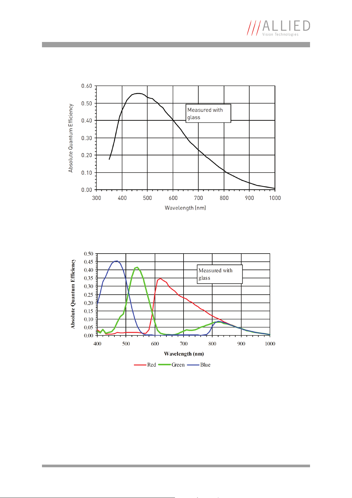
Specifications
Figure 45: Spectral sensitivity of Pike F-421B
Figure 46: Spectral sensitivity of Pike F-421C
PIKE Technical Manual V5.0.0
99
Page 100

Specifications
Sensor Response
0%
10%
20%
30%
40%
50%
60%
400 500 600 700 800 900 1000 1100
Wavelength [nm]
Quantum Efficiency
Monochrome
Sensor Response
0%
5%
10%
15%
20%
25%
30%
35%
40%
45%
400 450 500 550 600 650 700 750
Wavelength [nm]
Quantum Efficiency
Red Green Blue
Figure 47: Spectral sensitivity of Pike F-505B
Figure 48: Spectral sensitivity of Pike F-505C
PIKE Technical Manual V5.0.0
100
 Loading...