

Allied Vision Prosilica GC660C, Prosilica GC1290C, Prosilica GC1600H, Prosilica GC1380CH, Prosilica GC1290 Technical Manual
...
GigE VISION CAMERAS
Prosilica GC
Technical Manual
V2.4.1
Allied Vision Technologies GmbH // Taschenweg 2a, 07646 Stadtroda / Germany 2018-Jun-19

Prosilica GC at a glance
Prosilica GC cameras have a GigE port and work with GigE hardware and cable
lengths up to 100 meters. Prosilica GC cameras are GigE Vision V1.2 and GenICam
SFNC V1.2.1 compliant.
Applied standards
Prosilica GC at a glance
GigE Vision®
GenICam™
The GigE Vision standard is an interface standard for digital machine vision
cameras administered by the AIA that is widely supported in the machine vision
industry. In contrast, Gigabit Ethernet is the network GigE Vision is built upon.
GenICam is a machine vision standard hosted by the EMVA. The aim of GenICam is
to provide a generic configuration interface for cameras and devices independent
of the used interface technology (for example, GigE Vision, USB3 Vision, DCAM
IEEE 1394, Camera Link). This approach enables proper interoperability between
GenICam compliant hardware and software solutions without the need for
customization.
The GenICam standard consists of multiple modules that specify tasks to be solved.
Allied Vision cameras and software make use of these modules, like the SFNC that
standardizes feature names and types via an XML file or the transport layer
interface (GenTL) that is used to grab images.
What else do you need?
Content URL
Camera data sheets
GigE Features Reference
Modular Concept
3D CAD STEP files
Software and firmware downloads
Technical papers and knowledge base https://www.alliedvision.com/en/support/
https://www.alliedvision.com/en/support/
technical-documentation/prosilica-gcdocumentation.html
technical-papers-knowledge-base.html
Read this manual carefully
Learn how to protect your camera from damage and fully understand its functions.
2Prosilica GC Technical Manual V2.4.1

Contact us
Connect with Allied Vision by function
https://www.alliedvision.com/en/meta-header/contact.html
Find an Allied Vision office or Allied Vision distribution partner
https://www.alliedvision.com/en/about-us/where-we-are.html
Email
For general inquiries, please contact info@alliedvision.com
For technical support, please contact support@alliedvision.com
Headquarters
Allied Vision Technologies GmbH
Taschenweg 2a, 07646 Stadtroda, Germany
Contact us
T// +49 36428-677-0 (Reception)
T// +49 36428-677-230 (Sales)
F// +49 36428 -677-28
President/CEO: Frank Grube
Registration Office: AG Jena HRB 208962
Tax ID: DE 184383113
3Prosilica GC Technical Manual V2.4.1

Contents
Contents
Prosilica GC at a glance 2
Applied standards . . . . . . . . . . . . . . . . . . . . . . . . . . . . . . . . . . . . . . . . . . . . . . . . . . . . . . . . . . . . . . . . . . . . . . . . . 2
What else do you need? . . . . . . . . . . . . . . . . . . . . . . . . . . . . . . . . . . . . . . . . . . . . . . . . . . . . . . . . . . . . . . . . . . . . 2
Contact us 3
Document history and conventions 8
Document history . . . . . . . . . . . . . . . . . . . . . . . . . . . . . . . . . . . . . . . . . . . . . . . . . . . . . . . . . . . . . . . . . . . . . . . . . 9
Manual conventions . . . . . . . . . . . . . . . . . . . . . . . . . . . . . . . . . . . . . . . . . . . . . . . . . . . . . . . . . . . . . . . . . . . . . . 11
Styles . . . . . . . . . . . . . . . . . . . . . . . . . . . . . . . . . . . . . . . . . . . . . . . . . . . . . . . . . . . . . . . . . . . . . . . . . . . . . . . 11
Symbols . . . . . . . . . . . . . . . . . . . . . . . . . . . . . . . . . . . . . . . . . . . . . . . . . . . . . . . . . . . . . . . . . . . . . . . . . . . . . 12
Product naming. . . . . . . . . . . . . . . . . . . . . . . . . . . . . . . . . . . . . . . . . . . . . . . . . . . . . . . . . . . . . . . . . . . . . . . 12
Acronyms and abbreviations . . . . . . . . . . . . . . . . . . . . . . . . . . . . . . . . . . . . . . . . . . . . . . . . . . . . . . . . . . . . 13
Compliance and intended use 15
Compliance notifications . . . . . . . . . . . . . . . . . . . . . . . . . . . . . . . . . . . . . . . . . . . . . . . . . . . . . . . . . . . . . . . . . . 16
For customers in Europe . . . . . . . . . . . . . . . . . . . . . . . . . . . . . . . . . . . . . . . . . . . . . . . . . . . . . . . . . . . . . . . 16
For customers in the USA. . . . . . . . . . . . . . . . . . . . . . . . . . . . . . . . . . . . . . . . . . . . . . . . . . . . . . . . . . . . . . . 16
For customers in Canada . . . . . . . . . . . . . . . . . . . . . . . . . . . . . . . . . . . . . . . . . . . . . . . . . . . . . . . . . . . . . . . 16
Pour utilisateurs au Canada . . . . . . . . . . . . . . . . . . . . . . . . . . . . . . . . . . . . . . . . . . . . . . . . . . . . . . . . . . . . . 16
Avoid electromagnetic interferences . . . . . . . . . . . . . . . . . . . . . . . . . . . . . . . . . . . . . . . . . . . . . . . . . . . . . 16
Camera applications and intended use . . . . . . . . . . . . . . . . . . . . . . . . . . . . . . . . . . . . . . . . . . . . . . . . . . . . . . . 17
General use . . . . . . . . . . . . . . . . . . . . . . . . . . . . . . . . . . . . . . . . . . . . . . . . . . . . . . . . . . . . . . . . . . . . . . . . . . 17
Use in medical devices . . . . . . . . . . . . . . . . . . . . . . . . . . . . . . . . . . . . . . . . . . . . . . . . . . . . . . . . . . . . . . . . . 17
Copyright and trademarks . . . . . . . . . . . . . . . . . . . . . . . . . . . . . . . . . . . . . . . . . . . . . . . . . . . . . . . . . . . . . . 17
Installation and hardware 18
General cautions and warnings . . . . . . . . . . . . . . . . . . . . . . . . . . . . . . . . . . . . . . . . . . . . . . . . . . . . . . . . . . . . . 19
Electrical connections. . . . . . . . . . . . . . . . . . . . . . . . . . . . . . . . . . . . . . . . . . . . . . . . . . . . . . . . . . . . . . . . . . 19
Optical components . . . . . . . . . . . . . . . . . . . . . . . . . . . . . . . . . . . . . . . . . . . . . . . . . . . . . . . . . . . . . . . . . . . 20
Configuring the host computer . . . . . . . . . . . . . . . . . . . . . . . . . . . . . . . . . . . . . . . . . . . . . . . . . . . . . . . . . . . . . 22
Installing the Ethernet adapter driver. . . . . . . . . . . . . . . . . . . . . . . . . . . . . . . . . . . . . . . . . . . . . . . . . . . . . 22
Optional: Modifying Ethernet adapter IP address . . . . . . . . . . . . . . . . . . . . . . . . . . . . . . . . . . . . . . . . . . . 22
Ethernet adapter driver settings . . . . . . . . . . . . . . . . . . . . . . . . . . . . . . . . . . . . . . . . . . . . . . . . . . . . . . . . . 23
Enabling jumbo packets . . . . . . . . . . . . . . . . . . . . . . . . . . . . . . . . . . . . . . . . . . . . . . . . . . . . . . . . . . . . . . . . 23
Connecting your camera. . . . . . . . . . . . . . . . . . . . . . . . . . . . . . . . . . . . . . . . . . . . . . . . . . . . . . . . . . . . . . . . . . . 24
Optics . . . . . . . . . . . . . . . . . . . . . . . . . . . . . . . . . . . . . . . . . . . . . . . . . . . . . . . . . . . . . . . . . . . . . . . . . . . . . . . . . . 24
Accessories. . . . . . . . . . . . . . . . . . . . . . . . . . . . . . . . . . . . . . . . . . . . . . . . . . . . . . . . . . . . . . . . . . . . . . . . . . . . . . 24
Downloading camera drivers . . . . . . . . . . . . . . . . . . . . . . . . . . . . . . . . . . . . . . . . . . . . . . . . . . . . . . . . . . . . . . . 25
Powering up the camera. . . . . . . . . . . . . . . . . . . . . . . . . . . . . . . . . . . . . . . . . . . . . . . . . . . . . . . . . . . . . . . . . . . 25
Connecting to host application . . . . . . . . . . . . . . . . . . . . . . . . . . . . . . . . . . . . . . . . . . . . . . . . . . . . . . . . . . . . . 25
Allied Vision software . . . . . . . . . . . . . . . . . . . . . . . . . . . . . . . . . . . . . . . . . . . . . . . . . . . . . . . . . . . . . . . . . . 26
Third-party software. . . . . . . . . . . . . . . . . . . . . . . . . . . . . . . . . . . . . . . . . . . . . . . . . . . . . . . . . . . . . . . . . . . 26
Specifications 27
4Prosilica GC Technical Manual V2.4.1

Contents
Notes on specifications. . . . . . . . . . . . . . . . . . . . . . . . . . . . . . . . . . . . . . . . . . . . . . . . . . . . . . . . . . . . . . . . . . . . 28
Frame memory . . . . . . . . . . . . . . . . . . . . . . . . . . . . . . . . . . . . . . . . . . . . . . . . . . . . . . . . . . . . . . . . . . . . . . . 28
Resolution and ROI frame rate . . . . . . . . . . . . . . . . . . . . . . . . . . . . . . . . . . . . . . . . . . . . . . . . . . . . . . . . . . 29
Absolute QE plots . . . . . . . . . . . . . . . . . . . . . . . . . . . . . . . . . . . . . . . . . . . . . . . . . . . . . . . . . . . . . . . . . . . . . 29
Spectral response plots . . . . . . . . . . . . . . . . . . . . . . . . . . . . . . . . . . . . . . . . . . . . . . . . . . . . . . . . . . . . . . . . 30
Specifications common to all models . . . . . . . . . . . . . . . . . . . . . . . . . . . . . . . . . . . . . . . . . . . . . . . . . . . . . 30
Prosilica GC660, GC660C . . . . . . . . . . . . . . . . . . . . . . . . . . . . . . . . . . . . . . . . . . . . . . . . . . . . . . . . . . . . . . . . . . 31
Absolute QE. . . . . . . . . . . . . . . . . . . . . . . . . . . . . . . . . . . . . . . . . . . . . . . . . . . . . . . . . . . . . . . . . . . . . . . . . . 32
Spectral response . . . . . . . . . . . . . . . . . . . . . . . . . . . . . . . . . . . . . . . . . . . . . . . . . . . . . . . . . . . . . . . . . . . . . 32
ROI frame rate. . . . . . . . . . . . . . . . . . . . . . . . . . . . . . . . . . . . . . . . . . . . . . . . . . . . . . . . . . . . . . . . . . . . . . . . 33
Prosilica GC1290, GC1290C . . . . . . . . . . . . . . . . . . . . . . . . . . . . . . . . . . . . . . . . . . . . . . . . . . . . . . . . . . . . . . . . 34
Absolute QE. . . . . . . . . . . . . . . . . . . . . . . . . . . . . . . . . . . . . . . . . . . . . . . . . . . . . . . . . . . . . . . . . . . . . . . . . . 35
Spectral response . . . . . . . . . . . . . . . . . . . . . . . . . . . . . . . . . . . . . . . . . . . . . . . . . . . . . . . . . . . . . . . . . . . . . 35
ROI frame rate. . . . . . . . . . . . . . . . . . . . . . . . . . . . . . . . . . . . . . . . . . . . . . . . . . . . . . . . . . . . . . . . . . . . . . . . 36
Prosilica GC1380H, GC1380CH. . . . . . . . . . . . . . . . . . . . . . . . . . . . . . . . . . . . . . . . . . . . . . . . . . . . . . . . . . . . . . 37
Absolute QE. . . . . . . . . . . . . . . . . . . . . . . . . . . . . . . . . . . . . . . . . . . . . . . . . . . . . . . . . . . . . . . . . . . . . . . . . . 38
Spectral response . . . . . . . . . . . . . . . . . . . . . . . . . . . . . . . . . . . . . . . . . . . . . . . . . . . . . . . . . . . . . . . . . . . . . 38
ROI frame rate. . . . . . . . . . . . . . . . . . . . . . . . . . . . . . . . . . . . . . . . . . . . . . . . . . . . . . . . . . . . . . . . . . . . . . . . 39
Prosilica GC1600H, GC1600CH . . . . . . . . . . . . . . . . . . . . . . . . . . . . . . . . . . . . . . . . . . . . . . . . . . . . . . . . . . . . . 40
Absolute QE. . . . . . . . . . . . . . . . . . . . . . . . . . . . . . . . . . . . . . . . . . . . . . . . . . . . . . . . . . . . . . . . . . . . . . . . . . 41
Spectral response . . . . . . . . . . . . . . . . . . . . . . . . . . . . . . . . . . . . . . . . . . . . . . . . . . . . . . . . . . . . . . . . . . . . . 41
ROI frame rate. . . . . . . . . . . . . . . . . . . . . . . . . . . . . . . . . . . . . . . . . . . . . . . . . . . . . . . . . . . . . . . . . . . . . . . . 42
Prosilica GC2450, GC2450C . . . . . . . . . . . . . . . . . . . . . . . . . . . . . . . . . . . . . . . . . . . . . . . . . . . . . . . . . . . . . . . . 43
Absolute QE. . . . . . . . . . . . . . . . . . . . . . . . . . . . . . . . . . . . . . . . . . . . . . . . . . . . . . . . . . . . . . . . . . . . . . . . . . 44
Spectral response . . . . . . . . . . . . . . . . . . . . . . . . . . . . . . . . . . . . . . . . . . . . . . . . . . . . . . . . . . . . . . . . . . . . . 44
ROI frame rate . . . . . . . . . . . . . . . . . . . . . . . . . . . . . . . . . . . . . . . . . . . . . . . . . . . . . . . . . . . . . . . . . . . . . . . 45
Prosilica GC model frame rate comparison. . . . . . . . . . . . . . . . . . . . . . . . . . . . . . . . . . . . . . . . . . . . . . . . . . . . 46
Prosilica GC model comparison . . . . . . . . . . . . . . . . . . . . . . . . . . . . . . . . . . . . . . . . . . . . . . . . . . . . . . . . . . . . . 46
Camera feature highlights . . . . . . . . . . . . . . . . . . . . . . . . . . . . . . . . . . . . . . . . . . . . . . . . . . . . . . . . . . . . . . . . . 47
Camera feature comparison. . . . . . . . . . . . . . . . . . . . . . . . . . . . . . . . . . . . . . . . . . . . . . . . . . . . . . . . . . . . . . . . 48
Image data flow . . . . . . . . . . . . . . . . . . . . . . . . . . . . . . . . . . . . . . . . . . . . . . . . . . . . . . . . . . . . . . . . . . . . . . . . . . 49
Mechanical dimensions 50
Prosilica GC model housing (C-Mount) . . . . . . . . . . . . . . . . . . . . . . . . . . . . . . . . . . . . . . . . . . . . . . . . . . . . . . . 51
Tripod adapter. . . . . . . . . . . . . . . . . . . . . . . . . . . . . . . . . . . . . . . . . . . . . . . . . . . . . . . . . . . . . . . . . . . . . . . . . . . 52
Flange focal distance. . . . . . . . . . . . . . . . . . . . . . . . . . . . . . . . . . . . . . . . . . . . . . . . . . . . . . . . . . . . . . . . . . . . . . 52
C-Mount. . . . . . . . . . . . . . . . . . . . . . . . . . . . . . . . . . . . . . . . . . . . . . . . . . . . . . . . . . . . . . . . . . . . . . . . . . . . . 52
Adjustment of C-Mount . . . . . . . . . . . . . . . . . . . . . . . . . . . . . . . . . . . . . . . . . . . . . . . . . . . . . . . . . . . . 53
Lens protrusion for C-Mount cameras . . . . . . . . . . . . . . . . . . . . . . . . . . . . . . . . . . . . . . . . . . . . . . . . . 54
Sensor position accuracy . . . . . . . . . . . . . . . . . . . . . . . . . . . . . . . . . . . . . . . . . . . . . . . . . . . . . . . . . . . . . . . . . . 55
IR cut filter . . . . . . . . . . . . . . . . . . . . . . . . . . . . . . . . . . . . . . . . . . . . . . . . . . . . . . . . . . . . . . . . . . . . . . . . . . . . . . 56
Camera interfaces 57
Back panel . . . . . . . . . . . . . . . . . . . . . . . . . . . . . . . . . . . . . . . . . . . . . . . . . . . . . . . . . . . . . . . . . . . . . . . . . . . . . . 58
Status LEDs. . . . . . . . . . . . . . . . . . . . . . . . . . . . . . . . . . . . . . . . . . . . . . . . . . . . . . . . . . . . . . . . . . . . . . . . . . . . . . 59
GigE port . . . . . . . . . . . . . . . . . . . . . . . . . . . . . . . . . . . . . . . . . . . . . . . . . . . . . . . . . . . . . . . . . . . . . . . . . . . . . . . 59
Camera I/O connector pin assignment . . . . . . . . . . . . . . . . . . . . . . . . . . . . . . . . . . . . . . . . . . . . . . . . . . . . . . . 60
I/O definition . . . . . . . . . . . . . . . . . . . . . . . . . . . . . . . . . . . . . . . . . . . . . . . . . . . . . . . . . . . . . . . . . . . . . . . . . 62
Camera power . . . . . . . . . . . . . . . . . . . . . . . . . . . . . . . . . . . . . . . . . . . . . . . . . . . . . . . . . . . . . . . . . . . . 62
5Prosilica GC Technical Manual V2.4.1

Contents
Isolated IO ground . . . . . . . . . . . . . . . . . . . . . . . . . . . . . . . . . . . . . . . . . . . . . . . . . . . . . . . . . . . . . . . . . . . . 62
RxD RS232 and TxD RS232 . . . . . . . . . . . . . . . . . . . . . . . . . . . . . . . . . . . . . . . . . . . . . . . . . . . . . . . . . . 62
Input triggers . . . . . . . . . . . . . . . . . . . . . . . . . . . . . . . . . . . . . . . . . . . . . . . . . . . . . . . . . . . . . . . . . . . . . 63
Output signals. . . . . . . . . . . . . . . . . . . . . . . . . . . . . . . . . . . . . . . . . . . . . . . . . . . . . . . . . . . . . . . . . . . . . 63
Signal ground . . . . . . . . . . . . . . . . . . . . . . . . . . . . . . . . . . . . . . . . . . . . . . . . . . . . . . . . . . . . . . . . . . . . . 64
Video iris . . . . . . . . . . . . . . . . . . . . . . . . . . . . . . . . . . . . . . . . . . . . . . . . . . . . . . . . . . . . . . . . . . . . . . . . . 64
Reserved . . . . . . . . . . . . . . . . . . . . . . . . . . . . . . . . . . . . . . . . . . . . . . . . . . . . . . . . . . . . . . . . . . . . . . . . . 64
Video iris output . . . . . . . . . . . . . . . . . . . . . . . . . . . . . . . . . . . . . . . . . . . . . . . . . . . . . . . . . . . . . . . . . . . . . . . . . 64
Camera trigger. . . . . . . . . . . . . . . . . . . . . . . . . . . . . . . . . . . . . . . . . . . . . . . . . . . . . . . . . . . . . . . . . . . . . . . . . . . 66
Camera I/O opto-isolated user circuit example . . . . . . . . . . . . . . . . . . . . . . . . . . . . . . . . . . . . . . . . . . . . . 66
Camera I/O non-isolated user circuit example . . . . . . . . . . . . . . . . . . . . . . . . . . . . . . . . . . . . . . . . . . . . . 67
Trigger timing diagram . . . . . . . . . . . . . . . . . . . . . . . . . . . . . . . . . . . . . . . . . . . . . . . . . . . . . . . . . . . . . . . . . . . . 68
Notes on triggering. . . . . . . . . . . . . . . . . . . . . . . . . . . . . . . . . . . . . . . . . . . . . . . . . . . . . . . . . . . . . . . . . . . . 69
Trigger rules. . . . . . . . . . . . . . . . . . . . . . . . . . . . . . . . . . . . . . . . . . . . . . . . . . . . . . . . . . . . . . . . . . . . . . . . . . 69
Cleaning optical components 71
Warranty . . . . . . . . . . . . . . . . . . . . . . . . . . . . . . . . . . . . . . . . . . . . . . . . . . . . . . . . . . . . . . . . . . . . . . . . . . . . . . . 72
Keep optical components clean . . . . . . . . . . . . . . . . . . . . . . . . . . . . . . . . . . . . . . . . . . . . . . . . . . . . . . . . . . . . . 72
Identifying impurities . . . . . . . . . . . . . . . . . . . . . . . . . . . . . . . . . . . . . . . . . . . . . . . . . . . . . . . . . . . . . . . . . . . . . 73
Locating impurities . . . . . . . . . . . . . . . . . . . . . . . . . . . . . . . . . . . . . . . . . . . . . . . . . . . . . . . . . . . . . . . . . . . . . . . 73
Materials for cleaning optical components. . . . . . . . . . . . . . . . . . . . . . . . . . . . . . . . . . . . . . . . . . . . . . . . . . . . 74
Cleaning Instructions. . . . . . . . . . . . . . . . . . . . . . . . . . . . . . . . . . . . . . . . . . . . . . . . . . . . . . . . . . . . . . . . . . . . . . 74
Cleaning with compressed air . . . . . . . . . . . . . . . . . . . . . . . . . . . . . . . . . . . . . . . . . . . . . . . . . . . . . . . . . . . 76
Firmware update 77
Appendix 82
Specifications common to all models . . . . . . . . . . . . . . . . . . . . . . . . . . . . . . . . . . . . . . . . . . . . . . . . . . . . . . . . 83
Prosilica GC650, GC650C (02-2110A, 02-2111A) . . . . . . . . . . . . . . . . . . . . . . . . . . . . . . . . . . . . . . . . . . . . . . . 84
Absolute QE. . . . . . . . . . . . . . . . . . . . . . . . . . . . . . . . . . . . . . . . . . . . . . . . . . . . . . . . . . . . . . . . . . . . . . . . . . 85
Spectral response . . . . . . . . . . . . . . . . . . . . . . . . . . . . . . . . . . . . . . . . . . . . . . . . . . . . . . . . . . . . . . . . . . . . . 85
ROI frame rate. . . . . . . . . . . . . . . . . . . . . . . . . . . . . . . . . . . . . . . . . . . . . . . . . . . . . . . . . . . . . . . . . . . . . . . . 86
Prosilica GC655, GC655C (02-2115A, 02-2116A) . . . . . . . . . . . . . . . . . . . . . . . . . . . . . . . . . . . . . . . . . . . . . . . 87
Absolute QE. . . . . . . . . . . . . . . . . . . . . . . . . . . . . . . . . . . . . . . . . . . . . . . . . . . . . . . . . . . . . . . . . . . . . . . . . . 88
Spectral response . . . . . . . . . . . . . . . . . . . . . . . . . . . . . . . . . . . . . . . . . . . . . . . . . . . . . . . . . . . . . . . . . . . . . 88
ROI frame rate. . . . . . . . . . . . . . . . . . . . . . . . . . . . . . . . . . . . . . . . . . . . . . . . . . . . . . . . . . . . . . . . . . . . . . . . 89
Prosilica GC750, GC750C (02-2160A, 02-2161A) . . . . . . . . . . . . . . . . . . . . . . . . . . . . . . . . . . . . . . . . . . . . . . . 90
Absolute QE. . . . . . . . . . . . . . . . . . . . . . . . . . . . . . . . . . . . . . . . . . . . . . . . . . . . . . . . . . . . . . . . . . . . . . . . . . 91
ROI frame rate. . . . . . . . . . . . . . . . . . . . . . . . . . . . . . . . . . . . . . . . . . . . . . . . . . . . . . . . . . . . . . . . . . . . . . . . 92
Prosilica GC780, GC780C (02-2117A, 02-2118A) . . . . . . . . . . . . . . . . . . . . . . . . . . . . . . . . . . . . . . . . . . . . . . . 93
Absolute QE. . . . . . . . . . . . . . . . . . . . . . . . . . . . . . . . . . . . . . . . . . . . . . . . . . . . . . . . . . . . . . . . . . . . . . . . . . 94
Spectral response . . . . . . . . . . . . . . . . . . . . . . . . . . . . . . . . . . . . . . . . . . . . . . . . . . . . . . . . . . . . . . . . . . . . . 94
ROI frame rate. . . . . . . . . . . . . . . . . . . . . . . . . . . . . . . . . . . . . . . . . . . . . . . . . . . . . . . . . . . . . . . . . . . . . . . . 95
Prosilica GC1020, GC1020C (02-2165A, 02-2165B, 02-2166A, 02-2166B) . . . . . . . . . . . . . . . . . . . . . . . . . . 96
Absolute QE. . . . . . . . . . . . . . . . . . . . . . . . . . . . . . . . . . . . . . . . . . . . . . . . . . . . . . . . . . . . . . . . . . . . . . . . . . 97
Spectral response . . . . . . . . . . . . . . . . . . . . . . . . . . . . . . . . . . . . . . . . . . . . . . . . . . . . . . . . . . . . . . . . . . . . . 97
ROI frame rate. . . . . . . . . . . . . . . . . . . . . . . . . . . . . . . . . . . . . . . . . . . . . . . . . . . . . . . . . . . . . . . . . . . . . . . . 98
Prosilica GC1350, GC1350C (02-2130A, 02-2131A) . . . . . . . . . . . . . . . . . . . . . . . . . . . . . . . . . . . . . . . . . . . . 99
Absolute QE. . . . . . . . . . . . . . . . . . . . . . . . . . . . . . . . . . . . . . . . . . . . . . . . . . . . . . . . . . . . . . . . . . . . . . . . . 100
6Prosilica GC Technical Manual V2.4.1

Contents
ROI frame rate. . . . . . . . . . . . . . . . . . . . . . . . . . . . . . . . . . . . . . . . . . . . . . . . . . . . . . . . . . . . . . . . . . . . . . . 101
Prosilica GC1380, GC1380C (02-2140A, 02-2141A) . . . . . . . . . . . . . . . . . . . . . . . . . . . . . . . . . . . . . . . . . . . . 102
Absolute QE. . . . . . . . . . . . . . . . . . . . . . . . . . . . . . . . . . . . . . . . . . . . . . . . . . . . . . . . . . . . . . . . . . . . . . . . . 103
Spectral response . . . . . . . . . . . . . . . . . . . . . . . . . . . . . . . . . . . . . . . . . . . . . . . . . . . . . . . . . . . . . . . . . . . . 103
ROI frame rate. . . . . . . . . . . . . . . . . . . . . . . . . . . . . . . . . . . . . . . . . . . . . . . . . . . . . . . . . . . . . . . . . . . . . . . 104
Prosilica GC1600, GC1600C (02-2150A, 02-2151A) . . . . . . . . . . . . . . . . . . . . . . . . . . . . . . . . . . . . . . . . . . . . 105
Absolute QE. . . . . . . . . . . . . . . . . . . . . . . . . . . . . . . . . . . . . . . . . . . . . . . . . . . . . . . . . . . . . . . . . . . . . . . . . 106
Spectral response . . . . . . . . . . . . . . . . . . . . . . . . . . . . . . . . . . . . . . . . . . . . . . . . . . . . . . . . . . . . . . . . . . . . 106
ROI frame rate. . . . . . . . . . . . . . . . . . . . . . . . . . . . . . . . . . . . . . . . . . . . . . . . . . . . . . . . . . . . . . . . . . . . . . . 107
Camera feature comparison. . . . . . . . . . . . . . . . . . . . . . . . . . . . . . . . . . . . . . . . . . . . . . . . . . . . . . . . . . . . . . . 109
Image data flow . . . . . . . . . . . . . . . . . . . . . . . . . . . . . . . . . . . . . . . . . . . . . . . . . . . . . . . . . . . . . . . . . . . . . . . . . 110
Prosilica GC monochrome models . . . . . . . . . . . . . . . . . . . . . . . . . . . . . . . . . . . . . . . . . . . . . . . . . . . . . . 110
Prosilica GC color models . . . . . . . . . . . . . . . . . . . . . . . . . . . . . . . . . . . . . . . . . . . . . . . . . . . . . . . . . . . . . . . . . 111
Prosilica GC750C . . . . . . . . . . . . . . . . . . . . . . . . . . . . . . . . . . . . . . . . . . . . . . . . . . . . . . . . . . . . . . . . . . . . . 112
Mechanical dimensions . . . . . . . . . . . . . . . . . . . . . . . . . . . . . . . . . . . . . . . . . . . . . . . . . . . . . . . . . . . . . . . . . . 113
Prosilica GC CCD model housing (C-Mount). . . . . . . . . . . . . . . . . . . . . . . . . . . . . . . . . . . . . . . . . . . . . . . 113
Prosilica GC CMOS model housing (C-Mount) . . . . . . . . . . . . . . . . . . . . . . . . . . . . . . . . . . . . . . . . . . . . . 114
Lens protrusion for C-Mount cameras . . . . . . . . . . . . . . . . . . . . . . . . . . . . . . . . . . . . . . . . . . . . . . . . . . . 115
Index 116
7Prosilica GC Technical Manual V2.4.1

Document history and conventions
This chapter includes:
• Document history
• Layout styles and symbols used in this manual
• Product naming
• Acronyms and abbreviations used in this manual
Prosilica GC Technical Manual V2.4.1 8

Document history and conventions
Document history
Version Date Remarks
V2.0.0 2011-Jul-22 New manual release status
V2.0.1 2011-Oct-07 Added note to figure 34
V.2.0.2 2012-Sep-21 Renamed Camera IO signals
Reworked cleaning optics section
V.2.0.3 2013-Jan-14 Updated the exposure control values
Updated the Frame rate vs. Height graphs
Removed the internal I/O circuit diagram
V2.0.4 2013-Mar-26 Added Status LEDs section
Added appendix
Updated the RoHS directive
Updated the pixel format naming according to the GenICam naming convention
Added caution regarding the drive voltage for the video iris lens
Added frame rate formulas in the Resolution and ROI frame rates chapter
V2.0.5 2013-May-07 Updated the exposure control values in the Specifications chapter
Added Vimba SDK link in the Additional references section
Updated Allied Vision recommended cabling to Cat 6 or higher in the Gigabit
Ethernet interface section
V2.0.6 2013-Jul-05 Added contact information for Allied Vision Technologies (Shanghai) Co. Ltd.
Updated the links to Allied Vision GigE Installation Manual
Added links to Allied Vision GigE Camera and Driver Features document
V2.0.7 2013-Oct-02 Added optical flange focal distance and maximum lens protrusion information
Updated Cleaning optics section
Updated vertical binning values in Specifications chapter
Updated Tab l e 1 7
Updated links for PvAPI SDK
V2.0.8 2013-Nov-26 Added chapter Description of the data path
Updated the Index
V2.1.0 2015-Mar-20 Updated Allied Vision logo
Replaced old links with new Allied Vision website links
Changed file name from ‘GigE Camera and Driver Features’ to ‘GigE Features
Reference’
Changed chapter name from ‘Description of data path’ to ‘Camera data path’
Replaced the optical flange focal distance section with C-Mount flange focal distance
section
Updated datapath diagram for Prosilica GC: color models
Updated exposure control and power requirements in Specifications chapter
Table 1: Document history
9Prosilica GC Technical Manual V2.4.1

Document history and conventions
Version Date Remarks
V2.2.0 2016-July-04 Changed the technical manual layout
Changed chapter name from Camera dimensions to Mechanical dimensions
Moved Sensor position accuracy section from Appendix to Mechanical dimensions
chapter
Added Appendix for all older Prosilica GC hardware revision A models
Added Cleaning optical components chapter to replace Cleaning optics section in
V2.1.0
Added Contact us section to replace Contacting Allied Vision section in V2.1.0
Added D revision feature changes for Prosilica GC660, GC660C, GC1290, GC1290C,
GC1380H, GC1380CH, GC1600H, GC1600CH, GC2450, GC2450C
Added Installation chapter
Removed image flow chapter and added the diagrams to the Appendix
Added new image flow diagram for new Prosilica GC hardware revision D models at
the end of the Specifications chapter
Updated frame rate information
Aligned the information in the Specification tables with the information on the
product web pages
Various other minor improvements and corrections
New trigger latency and trigger jitter values for Prosilica GC hardware revision D
models
Updated absolute QE plots and new spectral response plots for all hardware revision
D models
For Prosilica GC660 and GC660C, the image width was changed from 659 to 658. It
was changed to 658 so that the color version would image with Vimba when using
default values.
Prosilica GC hardware revision A models support five user sets. Prosilica GC hardware
revision D models support three user sets.
Added optical filter information to specification tables
New features for hardware revision D models include:
• Gamma correction
• Three look-up tables
• Hue, saturation, and color transformation
• Main board temperature readout
V2.2.1 2017-Feb-10 Updated QE plot and added spectral response plots
Corrected error in Installation and hardware chapter
V2.2.2 2017-Apr-07 Added cable color to camera I/O connector pin assignment including pin assignment
figure and cross reference to the Allied Vision I/O cable data sheet
V2.2.3 2017-May-24 Corrected the measurements for the Prosilica GC750
Added note to all models that dimensions include connectors and C-Mount
Updated the measurements to reflect the dimensions shown in the technical drawing
Table 1: Document history (continued)
10Prosilica GC Technical Manual V2.4.1

Document history and conventions
Version Date Remarks
V2.3.0 2017-Oct-18 Removed references to Prosilica GC660, GC1290, GC1380H, GC1600H, GC2450
hardware revision A models in the Appendix. The last time shipment period for these
models ended on June 30, 2017 as detailed in PCN AVTPR-112. These hardware
revision A models were replaced by hardware revision D models.
Changed Cell size terminology to Pixel size
Various other minor improvements and corrections
V2.4.0 2017-Dec-15 Updated exposure time values (GC660, GC1290, GC1380H, GC2450) and gain values
(GC1600H, GC2450) for latest firmware
Added Specifications common to all models to simplify the model specific tables
Simplified the Contact us section, please click the link to find contact information
for your region or email us at one of the provided email addresses.
Various other minor enhancements and corrections
V2.4.1 2018-Jun-19
Updated symbols used in this manual
Updated RoHS statement to include amendment 2015/863/EU
Table 1: Document history (continued)
Manual conventions
To give this manual an easily understood layout and to emphasize important
information, the following typographical styles and symbols that are used.
Styles
Style Function Example
Bold Program names, UI elements, highlighting
Italics Publication names, chapter titles, UI non-
Courier New Code listings, feature names Input
Courier New Italics Feature options Mode
Blue Cross references, web page links, email links Link
Table 2: Character styles used in this manual
bold
important things
Italics
interactive elements
11Prosilica GC Technical Manual V2.4.1

Document history and conventions
i
Symbols
NOTICE
Material damage
Precautions as described.
NOTICE
Material damage by electrostatic discharge (ESD)
Precautions as described.
CAUTION
Personal injuries
Precautions as described.
Safety-related instructions to avoid malfunctions
This symbol indicates important or specific instructions or procedures that are
related to product safety. You have to follow these instructions to avoid
malfunctions.
Practical hint
This symbol highlights a practical hint that helps to better understand the camera‘s
features and functions, and to make better use of it.
Further information available online
This symbol highlights URLs for further information. The URL itself is shown in blue.
Example:
https://www.alliedvision.com
Product naming
Names of third-party products in this document are shortened to ease reading.
Nevertheless, we respect all manufacturer rights and trademarks.
Official product name Naming in this manual Manufacturer website
Sony Semiconductor Solutions Sony http://www.sony-semicon.co.jp/
ON Semiconductor ON Semi http://www.onsemi.com/
Table 3: Third-party product naming used in this manual
12Prosilica GC Technical Manual V2.4.1

Document history and conventions
Acronyms and abbreviations
The following table provides a list of abbreviations used in this document.
Acronym or
Abbreviation
°C
AIA Automated Imaging Association
CAD Computer aided design
Cat 6 Category 6, Ethernet cable
CCD Charge-coupled device
CMOS Complementary metal-oxide semiconductor
dB
DHCP Dynamic Host Control Protocol
EMVA European Machine Vision Association
Description
Degrees Celsius
Decibel
ESD Electrostatic discharge
FIFO First-in first-out
fps Frames per second
g Grams
GigE Gigabit Ethernet
GND Ground (power)
GVSP GigE Vision Streaming Protocol
H × V Horizontal × Vertical (sensor resolution measurement)
I/O Input/Output
KΩ Kiloohm
mA Milliampere
MB Megabyte
Mbps Megabits per second
mm Millimeter
MP Megapixel
MSDS Material safety data sheet
nm Nanometer
ns Nanosecond
psi Pound per square inch (atmospheric pressure)
QE Quantum efficiency
RoHS Restriction of Hazardous Substances Directive
ROI Region of interest
Table 4: Acronyms and abbreviations used in this document
13Prosilica GC Technical Manual V2.4.1

Document history and conventions
Acronym or
Abbreviation
Description
s Second
SDK Software Development Kit
SFNC Standard Feature Naming Convention
TTL I/O Transistor-transistor logic input/output
TxD and RxD
Transmit and receive
V Volts
VDC Volts of direct current
W Watts
WEEE Waste of Electric and Electronic Equipment
XML Extensible Markup Language
µA Microampere
μm
µs
Micrometer or micron
Microsecond
Table 4: Acronyms and abbreviations used in this document (continued)
14Prosilica GC Technical Manual V2.4.1

§
Compliance and intended use
This chapter includes:
• Information about the legal requirements and
restrictions for Prosilica GC cameras based on
current and relevant regulations
• Particular emphasis has been given to Europe,
the U.S., and Canada
• Intended use statements
Prosilica GC Technical Manual V2.4.1 15

Compliance notifications
For customers in Europe
Allied Vision has demonstrated the fulfillment of the requirements relating to the
Prosilica GC camera family:
• Directive 2014/30/EU (Electromagnetic compatibility)
• Directive 2011/65/EU, including amendment 2015/863/EU (RoHS)
• Directive 2012/19/EU (WEEE)
For customers in the USA
Class A digital device
Note: This equipment has been tested and found to comply with the limits for a
Class A digital device, pursuant to part 15 of the FCC Rules. These limits are
designed to provide reasonable protection against harmful interference when the
equipment is operated in a commercial environment. This equipment generates,
uses, and can radiate radio frequency energy and, if not installed and used in
accordance with the instruction manual, may cause harmful interference to radio
communications. Operation of this equipment in a residential area is likely to
cause harmful interference in which case the user will be required to correct the
interference at his own expense.
We caution the user that changes or modifications not expressly approved by the
party responsible for compliance could void the user's authority to operate the
equipment.
Compliance and intended use
For customers in Canada
This apparatus complies with the Class A limits for radio noise emissions set out in
the Radio Interference Regulations.
CAN ICES-003
Pour utilisateurs au Canada
Cet appareil est conforme aux normes classe A pour bruits radioélectriques,
spécifiées dans le Règlement sur le brouillage radioélectrique.
CAN ICES-003
Avoid electromagnetic interferences
For all power and interface connections, only use shielded cables or cables
recommended by Allied Vision.
16Prosilica GC Technical Manual V2.4.1

Compliance and intended use
Camera applications and intended use
General use
• The user is responsible for operating the camera within the specifications that
are defined in this document, and within appropriate environmental
conditions and technical prerequisites, to ensure trouble-free camera
operation.
• The camera is compliant with current data communication standards;
however, those standards do not allow for self-monitoring. Thus, the camera
cannot be used as a standalone device for security-related monitoring
operations.
• The camera is a hardware product. Only when used with appropriate
accompanying software, the camera will produce the desired results. The
realization of intelligent solutions requires additional software that is suitable
to run with the camera.
• The camera is a component, it is neither a complete product, nor is it a readymade technical solution.
• The camera-supporting software can be obtained and installed separately
from the camera. Usage of the software is solely the responsibility of the user.
• The camera must not be opened. For all repair tasks, contact Allied Vision or
one of Allied Vision's authorized representatives.
• Observe the intended use. The camera must only be used for purposes that
are in conformity with the stated intended use.
• Additionally, refer to the warranty information on the Allied Vision website.
Use in medical devices
The camera provides basic adequacy to be used in medical devices as well,
however, is not specially designated for operation in medical devices. When used
as part of a medical device, a review of the specific application is necessary. Users
who integrate the camera into an application must comply with the rules and
regulations concerning medical devices.
Copyright and trademarks
All text, pictures, and graphics are protected by copyright and other laws
protecting intellectual property. All content is subject to change without notice.
All trademarks, logos, and brands cited in this document are property and/or
copyright material of their respective owners. Use of these trademarks, logos, and
brands does not imply endorsement.
Copyright © 2018 Allied Vision GmbH. All rights reserved.
17Prosilica GC Technical Manual V2.4.1

Installation and hardware
This chapter describes the components required for
your vision system including configuring the host
computer, Ethernet adapter settings, and connecting
your Prosilica GC camera.
Prosilica GC Technical Manual V2.4.1 18

General cautions and warnings
Electrical connections
NOTICE
Material damage by electrostatic discharge (ESD)
The phenomenon is commonly known: when walking on a carpet, we get charged.
Touching a door handle, we get an electric shock. ESD is dangerous for electronic
devices, especially when tools or hands get in contact with connectors. We
recommend measures to avoid damage by ESD:
• Unpacking: Remove the camera from its anti-static packaging only when your
body is grounded.
• Workplace: Use a static-safe workplace with static-dissipative mat and air
ionization.
• Wrist strap: Wear a static-dissipative wrist strap to ground your body.
• Clothing: Wear ESD-protective clothing. Keep components away from your
body and clothing. Even if you are wearing a wrist strap, your body is
grounded but your clothes are not.
Installation and hardware
NOTICE
Do not operate the camera beyond the environmental specifications
See environmental specifications limits in the Specifications section of this
document. Special care must be taken to maintain a reasonable operating
temperature.
NOTICE
Verify all external connections
Verify all external connections in terms of voltage levels, power requirements,
voltage polarity, and signal integrity prior to powering the device.
19Prosilica GC Technical Manual V2.4.1
Installation and hardware
Operation outside the allowed temperature range can damage the camera. For
best performance and to protect the camera from damage, keep the housing
temperature between the specified operating temperature.
Observe the following:
• To avoid camera crashes, operate the camera with a lens or lens adapter
attached only.
• For maximum heat dissipation, affix the camera to a heat sink, using the
mounting threads.
- Use mounting base and heat sink with large surface areas.
- Use a mounting base with a high thermal conductivity.
• Reduce ambient temperature. For example, in an outdoor application with
direct sunlight, provide shading by an enclosure.
• Provide ventilation or other active cooling of camera, mounting base, and heat
sink.
NOTICE
Heat dissipation
Operation outside the allowed temperature range can damage the camera. For
best performance and to protect the camera from damage, keep the housing
temperature between the specified operating temperature.
Observe the following:
• To avoid camera crashes, operate the camera with a lens or lens adapter
attached only.
• For maximum heat dissipation, affix the camera to a heat sink, using the
mounting threads.
- Use mounting base and heat sink with large surface areas.
- Use a mounting base with a high thermal conductivity.
• Reduce ambient temperature. For example, in an outdoor application with
direct sunlight, provide shading by an enclosure.
• Provide ventilation or other active cooling of camera, mounting base, and heat
sink.
Optical components
NOTICE
Image sensor
Image sensors are sensitive to excessive radiation: focused sunlight, lasers, and
x-rays can damage the sensor. Monochrome models are not fitted with filter or
protection glass. Consider, when removing the lens or dust cap on these cameras,
the sensor is not protected against dirt or scratches.
20Prosilica GC Technical Manual V2.4.1

Installation and hardware
NOTICE
Cleaning optical components
This product can be damaged by some volatile cleaning agents. Avoid cleaning the
image sensor unless absolutely necessary. See instructions on optics cleaning in
this document.
Allied Vision can clean your camera as a service for you, if necessary. For more
information, contact Allied Vision support at https://www.alliedvision.com/en/
support/contact-support-and-repair.html.
NOTICE
Lenses
Provide the following conditions to keep dirt and droplets out of the optical system
of camera and lens:
• Dust-free environment
• Low relative humidity
•No condensation
To keep dirt out of the lens mount, hold the camera with the lens mount facing the
ground. Keep filter and camera back lens clean, because dirt becomes more visible
the closer it gets to the sensor.
21Prosilica GC Technical Manual V2.4.1

Configuring the host computer
Allied Vision GigE Vision cameras can operate on 10/100 or Gigabit speed Ethernet
adapters. In order to reach the maximum camera frame rate, a Gigabit speed
Ethernet adapter with jumbo packet support is required.
If your host computer has an available Ethernet port, this can be used with Allied
Vision GigE cameras. We recommend that your camera system uses a dedicated
Ethernet port not shared with Internet or local area networks. If more ports are
needed, or your existing Ethernet adapter is unable to operate at GigE speeds,
installing additional hardware may be required.
Usage on mixed-use networks (with printers, Internet, email) is possible but may
impact camera performance (for example, framerate). Check with your IT
administrator if required for network configuration.
Installing the Ethernet adapter driver
Installation and hardware
Install the network card driver from your network card manufacturer. If no
installation application is provided, update the driver manually.
To update the driver manually
1. Click the Start icon and select Control Panel in the menu.
2. Click View by Large Icons and select Device Manager in the list.
3. Under Network Adapters, locate the Ethernet network adapter, right-click the
entry, and select Update Driver Software in the menu.
4. Select the Search automatically for updated driver software or Browse my
computer for driver software.
5. Click Close once the driver has been installed.
Optional: Modifying Ethernet adapter IP address
After initial Ethernet adapter hardware installation, connect the Ethernet adapter
directly to the camera. The default configuration assigns an IP address
automatically using the Link-Local Address range of 169.254.xxx.xxx or an address
defined by the DHCP server, if present.
Users can fix the adapter address to minimize the time required for a camera to be
recognized by the host application. Systems that employ multiple Ethernet
adapters connected to multiple cameras will also be required to fix the address of
the Ethernet adapter.
To connect to the camera, edit the host PC’s adapter settings and configure the
following settings:
• IP Address: 169.254.100.1
• Subnet mask: 255.255.0.0
• Default gateway: blank
22Prosilica GC Technical Manual V2.4.1

Installation and hardware
i
Ethernet adapter driver settings
The Ethernet adapter should be adjusted to improve system performance when
using a GigE Vision camera. This performance is related to minimizing CPU usage
and dropped or resent packets.
Edit the Ethernet adapter driver properties according to the values in the following
table. The names and availability of the properties listed may vary depending on
adapter manufacturer and model.
Property Value
Packet size or maximum transmission unit (MTU) 8228 bytes or larger
Interrupt Moderation Enable
Interrupt Moderation Rate Extreme
Receive Buffers Maximum value configurable
Transmit Buffers 256 bytes
Default packet size
The default packet size of Allied Vision GigE cameras is 8228 bytes. The host
network adapter needs to support a packet size of equal or larger size to stream
from the camera.
Ethernet adapter
For desktop systems, use a PCI Express bus Ethernet adapter. For laptops, use an
expansion slot via an ExpressCard®.
A list of Allied Vision recommended Ethernet adapters is available on the Allied
Vision website. See the Hardware Selection for Allied Vision GigE Cameras
application note at https://www.alliedvision.com/en/support/technical-papers-
knowledge-base.html.
Ethernet adapter settings
The Ethernet adapter settings may also vary depending on your system
configuration and the network adapter manufacturer.
Enabling jumbo packets
Jumbo Frames or Jumbo Packets
The properties listed for the network adapter may include either Jumbo Packet or
Jumbo Frames depending on the manufacturer. If neither is listed under
properties, your network card may not support this feature. You must use a
network adapter that supports Jumbo Frames or Jumbo Packets.
To enable jumbo packets
1. Click the Start icon and select Control Panel in the menu.
23Prosilica GC Technical Manual V2.4.1

2. Click View by Large Icons and select Device Manager in the list.
i
i
3. Under Network Adapters, locate the Ethernet network adapter, right-click the
entry, and select Properties in the menu.
4. Select the Advanced tab.
5. Select the property Jumbo Packet and set the value to 9014 Bytes.
6. Click OK to save the setting.
Connecting your camera
Use a Cat 6 or higher rated Ethernet cable to connect the camera to the host
adapter. Crossover cabling is not required but does work. The camera has circuitry
to determine if a crossover cable is being used.
Allied Vision recommends Cat 6 or higher rated Ethernet cables for Prosilica GC
cameras. A different rating may not sustain peak interface bandwidth; leading to
lost connectivity or image data coming from the camera.
Installation and hardware
Optics
Allied Vision Prosilica GC cameras offer various mechanical interfaces for installing
a lens including C-Mount and CS-Mount. Lenses can be purchased directly from
Allied Vision or from an Allied Vision distributor. Users need to select the desired
focal length and appropriate optical format for the target camera model.
Accessories
Allied Vision offers a wide range of accessories for the use of Allied Vision GigE
cameras and the easy integration in already existing applications including:
• GigE accessories including standard GigE components.
For more information on mechanical interface options for your Prosilica GC
camera, see the Modular Concept at https://www.alliedvision.com/en/support/
technical-documentation.html.
Contact your Allied Vision Sales team or your local Allied Vision distribution
partner for information on accessories and lens recommendations:
https://www.alliedvision.com/en/about-us/where-we-are.html
24Prosilica GC Technical Manual V2.4.1

• Lenses for corresponding sensor sizes and resolutions.
i
i
i
Contact your Allied Vision Sales team or your local Allied Vision distribution
partner for information on accessories and lens recommendations:
https://www.alliedvision.com/en/about-us/where-we-are.html
Recommended accessories
A list of Allied Vision recommended accessories is available on the Allied Vision
website. See the Hardware Selection for Allied Vision GigE Cameras Application
Note at https://www.alliedvision.com/en/support/technical-papers-knowledge-
base.html.
Downloading camera drivers
Installation and hardware
Allied Vision GigE cameras work with the following software options.
Vimba Viewer or Vimba SDK:
https://www.alliedvision.com/en/products/software
Third-party software solutions:
https://www.alliedvision.com/en/products/software/third-party-libraries.html
Powering up the camera
A camera power adapter for each GigE camera is available from Allied Vision. See
Specifications on page 27 for connector definition and voltage specifications.
For Prosilica GC cameras
• Use only DC power supplies with insulated cases.
• For all power connections use only shielded cables to avoid electromagnetic
interferences.
NOTICE
Connecting to host application
Once you have installed the Vimba Viewer or third-party application to your host
computer, you can connect your Allied Vision GigE camera via an Ethernet cable.
Connect the Hirose cable to power the camera to power the camera.
25Prosilica GC Technical Manual V2.4.1

Installation and hardware
Allied Vision software
All software packages provided by Allied Vision are free of charge and contain the
following components:
•Drivers
• SDK for camera control and image acquisition
• Examples based on the provided APIs of the SDK
• Documentation and release notes
• Viewer application to operate and configure the cameras
Vimba Viewer documentation
Vimba Viewer documentation is included with the software download. Once
Vimba Viewer is installed on your host PC, documentation is located under
\Program Files\Allied Vision\Vimba.
Third-party software
In addition to the software provided by Allied Vision, there are numerous GigE
Vision standard compliant third-party software options available. In general, thirdparty software provides increased functionality such as image processing and
video recording.
Allied Vision’s Vimba SDK is based on the GenICam standard. GenICam-based
third-party software automatically connects with Vimba's transport layers.
Additionally, Vimba includes the Cognex Adapter for VisionPro.
26Prosilica GC Technical Manual V2.4.1

Specifications
This chapter provides:
• Technical specifications
• Absolute QE plots
• Spectral response plots
• ROI height vs. frame rate plots
• Camera feature comparison for hardware revision
D models (serial number 02-21XXD-XXXXX)
• Image data flow diagram
Prosilica GC Technical Manual V2.4.1 27

Notes on specifications
Dimensions and mass
Dimensions include C-Mount and connectors but not the tripod and lens.
Mass does not include the tripod and lens.
Hardware revision
This chapter includes camera specifications for all Prosilica GC models (hardware
revision D). For previous Prosilica GC models (hardware revision A) see Appendix
on page 82.
Hardware revision incompatibility
Prosilica GC hardware revision D models and firmware are not compatible with
Prosilica GC hardware revision A models.
Specifications
NOTICE
Monochrome models
As monochrome models do not have an optical filter always attach a dust cap
when a lens is not attached to minimize the possibility of contaminants falling on
the sensor surface.
Frame memory
Normally, an image is captured and transported in consecutive steps. The image is
taken, read out from the sensor, digitized and sent over the GigE network. Prosilica
GC cameras are equipped with an image buffer. The memory operates according to
the FIFO principle. Specification tables show how many frames can be stored by
each model.
Number of frames
The number of frames (
format, and GVSP packet size. The stated number of frames is typical for full
resolution, Mono8 or Bayer8, and a
packet.
StreamHoldCapacity) depends on resolution, pixel
GevSCPSPacketSize = 8192 bytes per
28Prosilica GC Technical Manual V2.4.1

Specifications
Resolution and ROI frame rate
This section charts the resulting frame rate from changing sensor height from full
image to a single line. Unless otherwise noted, sensors do not give an increase in
readout speed with a reduction in width.
Resolution and ROI measurements
• Data was generated using
bandwidth) and an 8-bit pixel format. Frame rates may be lower if using
network hardware incapable of 124 Mbps.
• ROIs are taken as center image for maximum speed advantage, where feature
OffsetY = (full sensor height – ROI height)/2.
BinningVertical is horizontal row summing on CCD before readout. The
•
frame rate for an ROI at the same effective height as binning is slower because
the CCD still needs to read out the “fast readout rows” in ROI mode.
Frame rate and readout
StreamBytesPerSecond = 124 Mbps (full
Although the sensor is capable of higher frame rates, readout is limited by GigE
bandwidth and exposure value. You can improve frame rates with a reduced ROI
and shorter exposure values.
Absolute QE plots
Important notice before reading the QE plots
All measurements were done without protection glass or IR cut filter. With
protection glass or filters, QE decreases by approximately 10%.
The uncertainty in measurement of the QE values is 10.25%. This is mainly due
to uncertainties in the measuring apparatus itself (Ulbricht sphere, optometer).
Manufacturing tolerance of the sensor increases overall uncertainty.
Absolute QE plots for Sony CCD sensors
Sony provides relative response curves in their sensor data sheets. To create the
absolute QE plots shown in this chapter, the relative response was converted to a
normalized QE response and then adjusted as per three measured QE values (at
448 nm, 529 nm, 632 nm) for color sensors and one measured QE value (at 529
nm) for monochrome sensors.
Absolute QE plots for ON Semi CCD sensors
The curves in the absolute QE plots shown in this chapter are from the sensor
manufacturer data sheet. The information was correct at the time of publishing.
Sensor specifications may change without notice.
29Prosilica GC Technical Manual V2.4.1
Specifications
Wavelength
The wavelength range in the absolute QE plots is based on the information
available in the sensor manufacturer data sheet at the time of publishing. Many
color sensors are documented by the sensor manufacturer only for wavelengths
from 400 nm to 700 nm.
For additional wavelength information, contact the sensor manufacturer.
Spectral response plots
Sony provides relative response curves in their sensor data sheets. To create the
spectral response plots shown in this chapter, the relative response was adjusted
as per three measured QE values (at 448 nm, 529 nm, 632 nm) for color sensors
and one measured QE value (at 529 nm) for monochrome sensors.
Specifications common to all models
Feature Specification
Lens mount Default: C-Mount
Optional: CS-Mount
TTL (non-isolated) I/Os 1 input, 1 output
Opto-isolated I/Os 1 input, 1 output
RS232 1
Operating temperature 0 °C to +50 °C ambient temperature (without condensation)
Storage temperature -10 °C to +70 °C ambient temperature (without condensation)
Operating humidity 20% to 80% non-condensing
Power requirements 5 to 25 VDC
Interface IIEEE 802.3 1000BASE-T (GigE)
Interface standard GigE Vision® Standard V1.2
Camera control standard GenICam SFNC V1.2.1
Temperature monitoring Available for main board only.
Resolution: 0.031; Accuracy: ± 1 °C
Table 5: Specifications common to all Prosilica GC models
30Prosilica GC Technical Manual V2.4.1

Specifications
Prosilica GC660, GC660C
Specification
Feature
Resolution 658 (H) × 494 (V)
Sensor Sony ICX618ALA with EXview HAD
CCD™ technology
Sensor type Interline CCD, Progressive Scan
Shutter type Global
Sensor format Typ e 1/4
Sensor size 4.5 mm diagonal
Pixel size 5.6 μm × 5.6 μm
Optical filter Default: No filter
Optional: See the Modular Concept
Maximum frame rate at full
resolution
Bit depth 8-bit, 12-bit
A/D 12-bit
Image buffer 64 MB
StreamHoldCapacity Up to 194 frames at full resolution
Monochrome pixel formats Mono8, Mono12, Mono12Packed Mono8
YUV color pixels formats YUV411Packed, YUV422Packed,
RGB color pixel formats RGB8Packed, BGR8Packed
RAW pixel formats BayerRG8, BayerRG12,
Exposure time control 10 µs to 72.9 s; 1 µs increments
Gain control 0 to 34 dB; 1 dB increments
Binning (Sum) Horizontal: 1 to 8 columns
Power consumption 3.0 W at 12 VDC
Trigger latency 0.9 µs for non-isolated I/O; 0.9 µs for isolated I/O
Trigger j i t ter ±50 ns for non-isolated I/O; ±50 ns for isolated I/O
Propagation delay (tpd) 10 ns for non-isolated I/O; 1.3 µs for isolated I/O
Body dimensions (L × W × H) 58.7 × 45.7 × 33 mm 59 × 45.7 × 33 mm
Mass (typical) 105 g
Prosilica GC660 Prosilica GC660C
0.3 MP
Sony ICX618AQ with EXview HAD
CCD™ technology
Default: IRC30 IR cut filter
Optional: See the Modular Concept
121 fps
YUV444Packed
BayerRG12Packed
Vertical: 1 to 14 rows
Table 6: Prosilica GC660, GC660C model specifications
31Prosilica GC Technical Manual V2.4.1

Absolute QE
0%
10%
20%
30%
40%
50%
60%
70%
80%
90%
400 450 500 550 600 650 700 750 800 850 900 950 1000
QuantumEfficiency[%]
Wavelength[nm]
SonyICX618absoluteQE
AllmeasurementsweredonewithoutprotectionglassorIRcutfilter.
Withprotectionglassorfilters,quantumefficiency(QE)decreasesbyapproximately10%.
TheuncertaintyinmeasurementoftheQEis+/Ͳ 10.25%.
Thevaluesaretypicalandaresubjecttominorvariations.
RedQE GreenQE BlueQE MonochromeQE
0.0000
0.1000
0.2000
0.3000
0.4000
400 450 500 550 600 650 700 750 800 850 900 950 1000
SpectralResponse[A/W]
Wavelength[nm]
SonyICX618spectralresponse
RedResponse GreenResponse BlueResponse MonochromeQE
Specifications
Figure 1: Prosilica GC660, GC660C (Sony ICX618) absolute QE
Spectral response
Figure 2: Prosilica GC660, GC660C (Sony ICX618) spectral response
32Prosilica GC Technical Manual V2.4.1

ROI frame rate
100
160
220
280
340
400
460
520
10 60 110 160 210 260 310 360 410 460 510
Framerate[fps]
ROIheight[pixels]
Specifications
Figure 3: Frame rate as a function of ROI height
Height (pixels) Frame rate (fps) Height (pixels) Frame rate (fps)
494 121.18 200 226.23
450 130.23 150 265.35
400 142.31 100 320.82
350 156.86 50 405.61
300 174.32 20 482.06
250 197.16 10 514.37
Width=658 pixels
Table 7: Frame rate as a function of ROI height
33Prosilica GC Technical Manual V2.4.1

Specifications
Prosilica GC1290, GC1290C
Specification
Feature
Resolution 1280 (H) × 960 (V)
Sensor Sony ICX445ALA with EXview HAD
CCD™ technology
Sensor type Interline CCD, Progressive Scan
Shutter type Global
Sensor format Typ e 1/3
Sensor size 6.0 mm diagonal
Pixel size 3.75 μm × 3.75 μm
Optical filter Default: No filter
Optional: See the Modular Concept
Maximum frame rate at full
resolution
Bit depth 8-bit, 12-bit
A/D 12-bit
Image buffer 64 MB
StreamHoldCapacity Up to 52 frames at full resolution
Monochrome pixel formats Mono8, Mono12, Mono12Packed Mono8
YUV color pixels formats YUV411Packed, YUV422Packed,
RGB color pixel formats RGB8Packed, BGR8Packed
RAW pixel formats BayerRG8, BayerRG12,
Exposure time control 12 µs to 72.4 s; 1 µs increments
Gain control 0 to 24 dB; 1 dB increments
Binning (Sum) Horizontal: 1 to 8 columns
Power consumption 3 W at 12 VDC
Trigger latency 1.7 µs for non-isolated I/O; 1.7 µs for isolated I/O
Trigger j i t ter ±50 ns for non-isolated I/O; ±50 ns for isolated I/O
Propagation delay (tpd) 10 ns for non-isolated I/O; 1.3 μs for isolated I/O
Body dimensions (L × W × H) 58.7 × 45.7 × 33 mm 59 × 45.7 × 33 mm
Mass (typical) 106 g
Prosilica GC1290 Prosilica GC1290C
1.2 MP
Sony ICX445AQA with EXview HAD
CCD™ technology
Default: IRC30 IR cut filter
Optional: See the Modular Concept
33 fps
YUV444Packed
BayerRG12Packed
Vertical: 1 to 14 rows
Table 8: Prosilica GC1290, GC1290C model specifications
34Prosilica GC Technical Manual V2.4.1

Absolute QE
0%
10%
20%
30%
40%
50%
60%
400 450 500 550 600 650 700 750 800 850 900 950 1000
QuantumEfficiency[%]
Wavelength[nm]
SonyICX445absoluteQE
AllmeasurementsweredonewithoutprotectionglassorIRcutfilter.
Withprotectionglassorfilters,quantumefficiency(QE)decreasesbyapproximately10%.
TheuncertaintyinmeasurementoftheQEis+/Ͳ 10.25%.
Thevaluesaretypicalandaresubjecttominorvariations.
RedQE GreenQE BlueQE MonochromeQE
0.0000
0.1000
0.2000
0.3000
400 450 500 550 600 650 700 750 800 850 900 950 1000
SpectralResponse[A/W]
Wavelength[nm]
SonyICX445spectralresponse
RedResponse GreenResponse BlueResponse MonochromeResponse
Specifications
Figure 4: Prosilica GC1290, GC1290C (Sony ICX445) absolute QE
Spectral response
Figure 5: Prosilica GC1290, GC1290C (Sony ICX445) spectral response
35Prosilica GC Technical Manual V2.4.1

ROI frame rate
0
50
100
150
200
250
300
350
0 100 200 300 400 500 600 700 800 900 1000
Framerate[fps]
ROIheight[pixels]
Specifications
Figure 6: Frame rate as a function of ROI height
Height (pixels) Frame rate (fps) Height (pixels) Frame rate (fps)
960 33.31 300 87.96
900 35.30 200 117.07
800 39.21 100 174.96
700 44.10 50 232.41
600 50.38 20 289.45
500 58.75 10 315.23
400 70.45 2 339.43
Width=1280 pixels
Table 9: Frame rate as a function of ROI height
36Prosilica GC Technical Manual V2.4.1

Specifications
Prosilica GC1380H, GC1380CH
Specification
Feature
Resolution 1360 (H) × 1024 (V)
Sensor Sony ICX285AL with EXview HAD
CCD™ technology
Sensor type Interline CCD, Progressive Scan
Shutter type Global
Sensor format Typ e 2/3
Sensor size 11.0 mm diagonal
Pixel size 6.45 μm × 6.45 μm
Optical filter Default: No filter
Optional: See the Modular Concept
Maximum frame rate at full
resolution
A/D 12-bit
Image buffer 64 MB
StreamHoldCapacity Up to 46 frames at full resolution
Bit depth 8-bit, 12-bit
Monochrome pixel formats Mono8, Mono12, Mono12Packed Mono8
YUV color pixels formats YUV411Packed, YUV422Packed,
RGB color pixel formats RGB8Packed, BGR8Packed
RAW pixel formats BayerRG8, BayerRG12,
Exposure time control 10 µs to 72.9 s; 1 µs increments
Gain control 0 to 33 dB; 1 dB increments
Binning (Sum) Horizontal: 1 to 8 columns
Power consumption 3.3 W at 12 VDC
Trigger latency 1.9 µs for non-isolated I/O; 1.9 µs for isolated I/O
Trigger j i t ter ±50 ns for non-isolated I/O; ±50 ns for isolated I/O
Propagation delay (tpd) 10 ns for non-isolated I/O; 1.3 μs for isolated I/O
Body dimensions (L × W × H) 58.7 × 45.7 × 33 mm 59 × 45.7 × 33 mm
Mass (typical) 111 g
Prosilica GC1380H Prosilica GC1380CH
1.4 MP
Sony ICX285AQ with EXview HAD
CCD™ technology
Default: IRC30 IR cut filter
Optional: See the Modular Concept
30 fps
YUV444Packed
BayerRG12Packed
Vertical: 1 to 14 rows
Table 10: Prosilica GC1380H, GC1380CH model specifications
37Prosilica GC Technical Manual V2.4.1

Absolute QE
0%
10%
20%
30%
40%
50%
60%
400 450 500 550 600 650 700 750 800 850 900 950 1000
QuantumEfficiency[%]
Wavelength[nm]
SonyICX285absoluteQE
AllmeasurementsweredonewithoutprotectionglassorIRcutfilter.
Withprotectionglassorfilters,quantumefficiency(QE)decreasesbyapproximately10%.
TheuncertaintyinmeasurementoftheQEis+/Ͳ 10.25%.
Thevaluesaretypicalandaresubjecttominorvariations.
RedQE GreenQE BlueQE MonochromeQE
0.0000
0.1000
0.2000
0.3000
400 450 500 550 600 650 700 750 800 850 900 950 1000
SpectralResponse[A/W]
Wavelength[nm]
SonyICX285spectralresponse
RedResponse GreenResponse BlueResponse MonochromeResponse
Specifications
Figure 7: Prosilica GC1380H, GC1380CH (Sony ICX285) absolute QE
Spectral response
Figure 8: Prosilica GC1380H, GC1380CH (Sony ICX285) spectral response
38Prosilica GC Technical Manual V2.4.1

ROI frame rate
20
40
60
80
100
120
140
160
180
200
220
0 150 300 450 600 750 900 1050
Framerate[fps]
ROIheight[pixels]
Specifications
Figure 9: Frame rate as a function of ROI height
Height (pixels) Frame rate (fps) Height (pixels) Frame rate (fps)
1024 30.48 300 76.89
1000 31.1 200 97.36
900 34 100 132.68
800 37.48 50 162.08
700 41.76 20 186.93
600 47.15 10 197.01
500 54.13 2 205.88
400 63.53
Width=1360 pixels
Table 11: Frame rate as a function of ROI height
39Prosilica GC Technical Manual V2.4.1

Specifications
Prosilica GC1600H, GC1600CH
Specification
Feature
Resolution 1620 (H) × 1220 (V)
Sensor Sony ICX274AL with Super HAD
CCD™ technology
Sensor type Interline CCD, Progressive Scan
Shutter type Global
Sensor format Type 1/1. 8
Sensor size 8.923 mm diagonal
Pixel size 4.4 μm × 4.4 μm
Optical filter Default: No filter
Optional: See the Modular Concept
Maximum frame rate at full
resolution
A/D 12-bit
Image buffer 64 MB
StreamHoldCapacity Up to 33 frames at full resolution
Bit depth 8-bit, 12-bit
Monochrome pixel formats Mono8, Mono12, Mono12Packed Mono8
YUV color pixels formats YUV411Packed, YUV422Packed,
RGB color pixel formats RGB8Packed, BGR8Packed
RAW pixel formats BayerRG8, BayerRG12,
Exposure time control 10 µs to 68.7 s; 1 µs increments
Gain control 0 to 30 dB; 1 dB increments
Binning (Sum) Horizontal: 1 to 8 columns
Power consumption 3.3 W at 12 VDC
Trigger latency 1.2 µs for non-isolated I/O; 1.2 µs for isolated I/O
Trigger j i t ter ±50 ns for non-isolated I/O; ±50 ns for isolated I/O
Propagation delay (tpd) 20 ns for non-isolated I/O; 0.5 μs for isolated I/O
Body dimensions (L × W × H) 58.7 × 45.7 × 33 mm 59 × 45.7 × 33 mm
Mass (typical) 105 g
Prosilica GC1600H Prosilica GC1600CH
2 MP
Sony ICX274AQ with Wfine Super HAD
CCD™ technology
Default: IRC30 IR cut filter
Optional: See the Modular Concept
25 fps
YUV444Packed
BayerRG12Packed
Vertical: 1 to 14 rows
Table 12: Prosilica GC1600H, GC1600CH model specifications
40Prosilica GC Technical Manual V2.4.1

Absolute QE
0%
10%
20%
30%
40%
50%
60%
70%
80%
400 450 500 550 600 650 700 750 800 850 900 950 1000
QuantumEfficiency[%]
Wavelength[nm]
SonyICX274absoluteQE
AllmeasurementsweredonewithoutprotectionglassorIRcutfilter.
Withprotectionglassorfilters,quantumefficiency(QE)decreasesbyapproximately10%.
TheuncertaintyinmeasurementoftheQEis+/Ͳ 10.25%.
Thevaluesaretypicalandaresubjecttominorvariations.
RedQE GreenQE BlueQE MonochromeQE
0.0000
0.1000
0.2000
0.3000
400 450 500 550 600 650 700 750 800 850 900 950 1000
SpectralResponse[A/W]
Wavelength[nm]
SonyICX274spectralresponse
RedResponse GreenResponse BlueResponse MonochromeResponse
Specifications
Figure 10: Prosilica GC1600H, GC1600CH (Sony ICX274) absolute QE
Spectral response
Figure 11: Prosilica GC1600H, GC1600CH (Sony ICX274) spectral response
41Prosilica GC Technical Manual V2.4.1

ROI frame rate
0
50
100
150
200
250
300
350
0 150 300 450 600 750 900 1050 1200 1350
Framerate[fps]
ROIheight[pixels]
Specifications
Figure 12: Frame rate as a function of ROI height
Height (pixels) Frame rate (fps) Height (pixels) Frame rate (fps)
1220 25.82 400 67.72
1100 28.39 300 84.42
1000 30.96 200 112.06
900 34.04 100 166.62
800 37.8 50 220.22
700 42.49 20 272.89
600 48.52 10 296.53
500 56.53 2 318.62
Width=1620 pixels
Table 13: Frame rate as a function of ROI height
42Prosilica GC Technical Manual V2.4.1

Specifications
Prosilica GC2450, GC2450C
Specification
Feature
Resolution; 2448 (H) × 2050 (V)
Sensor Sony ICX625ALA with Super HAD
CCD™ technology
Sensor type Interline CCD, Progressive Scan
Shutter type Global
Sensor format Typ e 2/3
Sensor size 11.016 mm diagonal
Pixel size 3.45 μm × 3.45 μm
Optical filter Default: No filter
Optional: See the Modular Concept
Maximum frame rate at full
resolution
A/D 12-bit
Image buffer 64 MB
StreamHoldCapacity Up to 12 frames at full resolution
Bit depth 8-bit, 12-bit
Monochrome pixel formats Mono8, Mono12, Mono12Packed Mono8
YUV color pixels formats YUV411Packed, YUV422Packed,
RGB color pixel formats RGB8Packed, BGR8Packed
RAW pixel formats BayerRG8, BayerRG12,
Exposure time control 10 µs to 48.0 s; 1 µs increments
Gain control 0 to 24 dB; 1 dB increments
Binning (Sum) Horizontal: 1 to 8 columns
Power consumption 3.8 W at 12 VDC
Trigger latency 0.8 µs for non-isolated I/O; 0.8 µs for isolated I/O
Trigger j i t ter ±50 ns for non-isolated I/O; ±50 ns for isolated I/O
Propagation delay (tpd) 20 ns for non-isolated I/O; 1.3 μs for isolated I/O
Body dimensions (L × W × H) 58.7 × 45.7 × 33 mm 59 × 45.7 × 33 mm
Mass (typical) 106 g
Prosilica GC2450 Prosilica GC2450C
5 MP
Sony ICX625AQA with Super HAD
CCD™ technology
Default: IRC30 IR cut filter
Optional: See the Modular Concept
15 fps
YUV444Packed
BayerRG12Packed
Vertical: 1 to 14 rows
Table 14: Prosilica GC2450, GC2450C model specifications
43Prosilica GC Technical Manual V2.4.1

Absolute QE
0%
10%
20%
30%
40%
50%
60%
400 450 500 550 600 650 700 750 800 850 900 950 1000
QuantumEfficiency[%]
Wavelength[nm]
SonyICX625absoluteQE
AllmeasurementsweredonewithoutprotectionglassorIRcutfilter.
Withprotectionglassorfilters,quantumefficiency(QE)decreasesbyapproximately10%.
TheuncertaintyinmeasurementoftheQEis+/Ͳ 10.25%.
Thevaluesaretypicalandaresubjecttominorvariations.
RedQE GreenQE BlueQE MonochromeQE
0.0000
0.1000
0.2000
0.3000
400 450 500 550 600 650 700 750 800 850 900 950 1000
SpectralResponse[A/W]
Wavelength[nm]
SonyICX625spectralresponse
RedResponse GreenResponse BlueResponse MonochromeResponse
Specifications
Figure 13: Prosilica GC2450, GC2450C (Sony ICX625) absolute QE
Spectral response
Figure 14: Prosilica GC2450, GC2450C (Sony ICX625) absolute QE
44Prosilica GC Technical Manual V2.4.1

ROI frame rate
10
20
30
40
50
60
70
80
90
0 300 600 900 1200 1500 1800 2100
Framerate[fps]
ROIheight[pixels]
Specifications
Figure 15: Frame rate as a function of ROI height
Height (pixels) Frame rate (fps) Height (pixels) Frame rate (fps)
2050 15.11 600 35.84
2000 15.42 400 44.21
1800 16.79 200 57.66
1600 18.42 100 68
1400 20.4 50 74.7
1200 22.87 20 79.4
1000 26.01 10 81.1
800 30.14 2 82.51
Width=2448 pixels
Table 15: Frame rate as a function of ROI height
45Prosilica GC Technical Manual V2.4.1
Specifications
0
100
200
300
400
500
600
0 250 500 750 1000 1250 1500 1750 2000 2250
Framerate[fps]
Height[pixels]
ProsilicaGCmodelcomparison
GC2450
GC1660
GC1380
GC1290
GC660
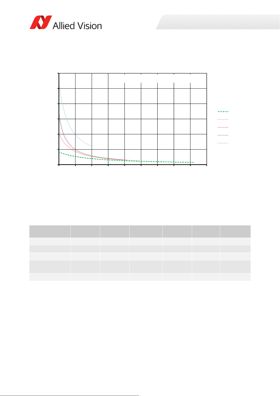
Prosilica GC model frame rate comparison
Figure 16: Maximum frame rate comparison for select models
Prosilica GC model comparison
Model Sensor Sensor type Sensor format Resolution Frame rate
GC660, GC660C Sony ICX618 CCD Typ e 1/4 658 × 494 121 fps 194 frames
GC1290, GC1290C Sony ICX445 CCD Type 1/ 3 1280 × 960 33 fps 52 frames
GC1380, GC1380C Sony ICX285 CCD Type 2/ 3 1360 × 1024 30 fps 46 frames
GC1600H,
GC1600CH
GC2450, GC2450C Sony ICX625 CCD Type 2/ 3 2448 × 2050 15 fps 12 frames
Sony ICX274 CCD Type 1/1.8 1620 × 1220 25 fps 33 frames
Table 16: Prosilica GC model overview
StreamHold
Capacity
46Prosilica GC Technical Manual V2.4.1

Camera feature highlights
i
Allied Vision cameras support a number of standard and extended features. The
following table identifies a selection of capabilities of the Prosilica GC camera
family.
Camera feature reference
A complete listing of camera features, including definitions can be found on the
Allied Vision Technical Documentation web page, go to https://www.alliedvi-
sion.com/en/support/technical-documentation.html.
• Vimba and third-party users: GigE Features Reference
•PvAPI users: GigE Camera and Driver Attributes document
Feature Description
Gain control Manual and auto
Exposure time control Manual and auto
White balance Red and blue channel; manual and auto control
External trigger event Rising edge, falling edge, any edge, level high, level low
External trigger delay 0 to 60* s; 1 µs increments
Fixed rate control 0.001 fps to maximum frame rate
Imaging modes Free-running, external trigger, fixed rate, software trigger
Sync out modes Trigger ready, trigger input, exposing, readout, imaging,
strobe, GPO
ROI Independent × and y control with 1 pixel resolution
Multicast Streaming to multiple computers
Event channel In-camera events including exposure start and trigger are
asynchronously broadcast to the host computer
Image chunk data Captured images are bundled with feature information
such as exposure and gain value
Color matrix Correct color rendering for specific color temperature
Gamma, hue, and saturation Adjust image gamma, hue, and saturation
IEEE 1588 Precision Time
Protocol (PTP)
*May vary depending on the camera model
Synchronize clocks of multiple cameras using multicast
messaging
Specifications
Figure 17: Prosilica GC camera and driver feature highlights
47Prosilica GC Technical Manual V2.4.1

Camera feature comparison
i
Allied Vision cameras support a number of standard and extended features. The
following table identifies a selection of capabilities and compares the availability of
features in Prosilica GC camera models.
Camera feature reference
A complete listing of camera features, including definitions can be found on the
Allied Vision Technical Documentation web page, go to https://www.alliedvi-
sion.com/en/support/technical-documentation.html.
• Vimba and third-party users: GigE Features Reference
•PvAPI users: GigE Camera and Driver Attributes document
GC660 GC1290 GC1380H GC1600H GC2450
Auto gain ✔ ✔ ✔ ✔ ✔
Auto exposure ✔ ✔ ✔ ✔ ✔
Auto white balance (color models only) ✔ ✔ ✔ ✔ ✔
Binning (Sum) ✔ ✔ ✔ ✔ ✔
Black level (Offset) ✔ ✔ ✔ ✔ ✔
Gamma correction ✔ ✔ ✔ ✔ ✔
Hue, saturation, color transformation (color
models only)
Three look-up tables (LUTs) ✔ ✔ ✔ ✔ ✔
Image optimization features
ROI ✔ ✔ ✔ ✔ ✔
Event channel ✔ ✔ ✔ ✔ ✔
Image chunk data ✔ ✔ ✔ ✔ ✔
IEEE 1588 Precision Time Protocol (PTP) ✔ ✔ ✔ ✔ ✔
RS232 ✔ ✔ ✔ ✔ ✔
Three storable user sets (config files) ✔ ✔ ✔ ✔ ✔
StreamHold ✔ ✔ ✔ ✔ ✔
Sync out modes ✔ ✔ ✔ ✔ ✔
Camera control features
Temperature monitoring (main board only) ✔ ✔ ✔ ✔ ✔
✔ ✔ ✔ ✔ ✔
Specifications
Table 17: Prosilica GC feature comparison
48Prosilica GC Technical Manual V2.4.1

Image data flow
i
Sensor
AnalogGain Offset
Analog Analog Analog Analog
ADC
Analog
Whitebalance
Horizontal
Binning
VerticalBinning
1
Gamma
LookͲupTable
1212
Bayer
Interpolation
Digital
Hue,Saturation,
Colortransformation
3
1
Colorinformationislostwhenverticalbinningisactive.
2
Colorpixelformatscanbe12or14bitsperpixeldependingonthepixelformatselected.
MonochromeandRAWpixelformatscanbe8,12,or14bitsperpixeldependingonthe
pixelformatselected.
3
Thenumberofbitsperpixelvariesdependingonthepixelformatselected.
4
TheoutputfromframememorytotheGigEinterfaceisdependentonthepixelformat
selected.
DigitalDigitalDigital
Digital
Digital2
Colorcamerasonly
Monochromecamerasand
RAWpixelformatsonly
VerticalROI
HorizontalROI
Histogram
Calculation
Digital
PixelFormatter
GigEVision
Streaming
Engine
GigEVisionMAC
FrameMemory
GigEInterface
GigE
Host
R/Y
G/U
B/V
R
G
B
The following diagram illustrates the data flow image data.
Camera feature reference
A complete listing of camera features, including definitions can be found on the
Allied Vision Technical Documentation web page, go to https://www.alliedvi-
sion.com/en/support/technical-documentation.html.
• Vimba and third-party users: GigE Features Reference
•PvAPI users: GigE Camera and Driver Attributes document
Prosilica GC hardware revision D models
Specifications
Figure 18: Image flow diagram for Prosilica GC (hardware revision D) models
49Prosilica GC Technical Manual V2.4.1

Mechanical dimensions
This chapter includes:
• CAD drawings and dimensions of standard
housing models
• Sensor position accuracy
• Maximum protrusion distance and filter diameter
for C-Mount and CS-Mount
Prosilica GC Technical Manual V2.4.1 50

Mechanical dimensions
i
M
3x4 (2x)
39.9
26
12.9*
58.7*
M3x4 (4x)
38
26
*Nominal value. Add 0.3 mm for
color cameras.
45.7
33
M3x4 (2x
)
26
42.9
^dWĮůĞƐĂƌĞĂǀĂŝůĂďůĞŽŶƚŚĞůůŝĞĚsŝƐŝŽŶ
dĞĐŚŶŝĐĂůŽĐƵŵĞŶƚĂƟŽŶǁĞďƐŝƚĞ
Prosilica GC cameras are available with different lens mount options. For more
information, see the Modular Concept document at:
https://www.alliedvision.com/en/support/technical-documentation.html
Prosilica GC model housing (C-Mount)
Prosilica GC660, GC1290, GC1380H, C1600H,
GC2450
Figure 19: Prosilica GC model housing dimensions
51Prosilica GC Technical Manual V2.4.1

Tripod adapter
0.5
0.5
24
26
32.5
9
18
6 PLCS TYP.
3.4 THRU
14
6 THRU
19.5
1
/4-20 Tapped Hole
THRU
6
4.5
A Prosilica GC camera can be mounted on a camera tripod by using a mounting
plate. The same tripod adapter can be used for all models within the Prosilica GC
camera family.
Prosilica GC tripod adapter
Contact your Allied Vision Sales representative or your local Allied Vision
distribution partner to purchase the Prosilica GC tripod adapter (Allied Vision
order code 02-5002A).
Mechanical dimensions
Figure 20: Tripod adapter for Prosilica GC series
Flange focal distance
C-Mount
Flange focal distance is the optical distance from the mounting flange to image
sensor die. Prosilica GC C-Mount cameras are optically calibrated to a standard
17.526 mm optical flange focal distance, with a ±10 µm tolerance.
C-Mount
Prosilica GC cameras are shipped with adjustable C-Mount. The camera can also
be built with a CS-Mount with a standard 12.50 mm optical flange focal distance
and a ± 10 µm tolerance.
52Prosilica GC Technical Manual V2.4.1

Mechanical dimensions
Adjustment of C-Mount
The C-Mount is adjusted at the factory and should not require adjusting. If for
some reason the lens mount requires adjustment, use the following method.
Figure 21: Prosilica GC camera and locking wrench
Loosen the locking ring
Use an adjustable wrench to loosen the locking ring. Be careful not to scratch the
camera. When the locking ring is loose, unthread the ring a few turns from the
camera face.
Lens tool - adjustment wrench
Contact the Allied Vision Sales team or your local Allied Vision distribution partner
to purchase the hexagonal lens adjustment wrench for Prosilica GC cameras with
C or CS locking ring (Allied Vision order code 02-5003A).
Adjusting the lens to infinity
Precondition: Use a C-Mount compatible lens that allows an infinity focus
1. Set the lens to infinity and image a distant object (10 m to 15 m). Make sure
the lens is firmly threaded onto the C-Mount ring.
2. Rotate the lens and C-Mount ring until the image is focused.
3. Carefully tighten the locking ring and recheck focus.
53Prosilica GC Technical Manual V2.4.1

Mechanical dimensions
Lens protrusion for C-Mount cameras
Lens protrusion is the distance from outer edge of C-Mount ring to contact point of
first surface internal to C-Mount ring. For color models this surface is the IR-filter
holder, and for monochrome models this surface is the internal camera front plate
(see figure 22). Table 18 presents lens protrusion values for Prosilica GC models
with C-Mount.
Lens protrusion
A
A
Front Plate
SecƟon A-A for C-Mount
monochrome cameras
Figure 22: Cross section of typical Prosilica GC assembly with C-Mount
Model Lens protrusion [mm] Model Lens protrusion [mm]
GC660 13.64 GC1380CH 8.31
GC660C 11.01 GC1600CH 6.98
GC1290 13.64 GC1600H 13.64
GC1290C 12.20 GC2450 13.64
Lens protrusion
/ZĐƵƚĮůƚĞƌ
holder
SecƟon A-A for C-Mount
color cameras
GC1380H 13.64 GC2450C 10.93
Table 18: Lens protrusion for Prosilica GC models with C-Mount
54Prosilica GC Technical Manual V2.4.1

Sensor position accuracy
x
y
Sensor case
D
Camera body
Pixel area
Sensor case
Camera body
Pixel area
Mechanical dimensions
Figure 23: Sensor position accuracy
The following table defines the manufacturing accuracy of fitting sensors into
Prosilica GC cameras.
Criteria Subject Properties
Reference Point Sensor Center of pixel area (photo sensitive cells)
Camera Center of camera front flange (outer case edges)
Accuracy ×-axis
y-axis
z-axis ±10 µm (optical back focal distance)
α
Alignment Optical alignment of photo sensitive sensor area
Table 19: Sensor position accuracy criteria
±400 µm (sensor shift)
± 1° (sensor rotation)
into camera front module (lens mount front
flange).
55Prosilica GC Technical Manual V2.4.1

IR cut filter
0
10
20
30
40
50
60
70
80
90
100
350 400 450 500 550 600 650 700 750 800 850 900 950
Transmission[%]
Wavelength[nm]
All Prosilica GC color models are equipped with an infrared block filter (IR cut
filter). This filter is employed to prevent infrared light from passing to the sensor. In
the absence of an IR filter, images are dominated by red and incapable of being
properly color balanced. Monochrome models do not employ an IR cut filter.
Figure 24 shows the filter transmission response for the IRC30 filter employed in
the Prosilica GC cameras.
Mechanical dimensions
Figure 24: IR cut filter transmission response
56Prosilica GC Technical Manual V2.4.1

Camera interfaces
This chapter includes:
• A general description of the inputs and outputs
(including trigger features)
• I/O connector pin assignments
• I/O block diagrams
• A general description of trigger rules such as
timing diagram and definitions
Prosilica GC Technical Manual V2.4.1 57

Back panel
i
4
32
1
Camera interfaces
This section provides information on GigE interface, inputs and outputs, and
trigger features.
Accessories
Contact your Allied Vision Sales representative or your local Allied Vision
distribution partner for information on accessories, go to:
https://www.alliedvision.com/en/about-us/where-we-are.html
Figure 25: Prosilica GC GigE port, Hirose I/O port, and LEDs
1 GigE port
2 LED1
3 LED2
4 Hirose I/O port
58Prosilica GC Technical Manual V2.4.1

Status LEDs
The color of the LEDs has the following meaning.
LED1 Flashing orange or solid
LED2 Flashing green Camera is powered
Table 20: Status of LEDs
LED2
Once the camera is booted, LED2 remains solid green as long as the camera is
powered, even if connection with the host is lost.
Camera interfaces
LED Color Status
Ethernet activity
orange
Solid green Camera is booted, and link with the host is
established
GigE port
The GigE port conforms to the IEEE 802.3 1000BASE-T standard for GigE over
copper. Allied Vision recommends using Cat 6 or higher compatible cabling and
connectors for best performance.
Ethernet adapters
See the Hardware Selection for Allied Vision GigE Cameras application note for a
list of recommended Ethernet adapters:
https://www.alliedvision.com/en/support/technical-papers-knowledgebase.html
A standard Ethernet adapter is available for purchase from Allied Vision:
Order code: 02-3002A
Model: Intel Pro 1000/PT
Ethernet cables
Cable lengths up to 100 meters are supported.
The 8-pin RJ45 jack has the pin assignment according to the Ethernet standard
(IEEE 802.3 1000BASE-T).
Allied Vision recommends using locking-screw cables from Components Express,
Inc. for a perfect fit. Visit the CEI product configurator to customize the cable
according to your needs.
59Prosilica GC Technical Manual V2.4.1
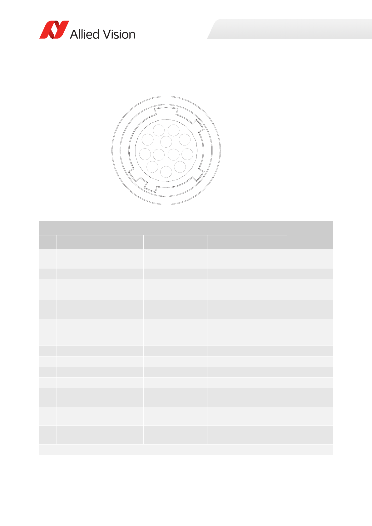
Camera I/O connector pin assignment
1 9
8
7
6
5
4
3
2
11 12
10
Camera interfaces
Camera side Hirose HR10A-10R-12PB connector
Pin Signal Direction Level Description
1 Camera GND In --- Ground for external
camera power supply
2 Camera Power In 5 to 16* VDC Camera power supply Red
3 In 1 In Uin(high) = 5 to 24 V
U
(low) = 0 to 0.8 V
in
4 Out 1 Out Open emitter max.
20 mA
5 Isolated IO GND In/Out --- Isolated input and output
6 Video iris Out --- PWM signal for iris control Green
7 Reserved --- --- --- Brown
8 TxD RS232 Out RS232 Terminal transmit data White
9 RxD RS232 In RS232 Terminal receive data Black
10 Signal GND --- --- Ground for RS232 and
11 In 2 In LVT TL
maximum 3.3 V
12 Out 2 Out LV TT L
maximum 3.3 V
*Some models offer 5 to 25 VDC. See Camera power for details.
Table 21: I/O connector pin assignment and I/O cable color coding
Input 1 opto-isolated
(SyncIn1)
Output 1 opto-isolated
(SyncOut1)
signal ground (Common
GND)
non-isolated IO
Input 2 non-isolated
(SyncIn2)
Output 2 non-isolated
(SyncOut2)
I/O cable
color code
Blue
Pink
Gray
Yellow
Orange
White and
Black
White and
Brown
60Prosilica GC Technical Manual V2.4.1

Camera interfaces
i
Hirose HR10A
.
.
.
.
.
.
.
.
.
.
.
.
SHIELD
1
2
3
4
5
6
7
8
9
10
11
12
.
BLUE
RED
PINK
GREY
YELLOW
GREEN
BROWN
WHITE
BLACK
ORANGE
WHITE/BLACK
WHITE/BROWN
Open End
.
.
.
.
.
.
.
.
.
.
.
.
TRANSPARENT
.
.
.
.
.
.
.
.
.
.
.
.
.
i
The general purpose I/O port uses a Hirose HR10A-10R-12PB connector on the
camera side. The mating cable connector is Hirose HR10A-10P-12S.
Hirose connector
The cable side Hirose connector is available for purchase from Allied Vision (Allied
Vision order code K7600040).
Cable color and pin out
For cable color and pin out information, see the Allied Vision I/O cable data sheet:
https://www.alliedvision.com/en/support/technical-documentation/accessoriesdata-sheets.html
Figure 26: Prosilica GC cable color coding
I/O definition
Camera power
The Prosilica GC camera family has recently been updated to offer an expanded
input power voltage range. The camera serial number is used to differentiate
between cameras that offer 5 to 16 VDC and those that offer 5 to 25 VDC.
NOTICE
Input power voltage range
• SN 02-XXXXX-06000 to 02-XXXXX-07999: 5 to 16 V. 12 V nominal.
•SN ≥ 02-XXXXX-08XXX: 5 to 25 V. 12 V nominal
Further information available online
For more information on the power voltage range update for the Prosilica GC
family, see the Prosilica GC Power Voltage Specification Update application note:
https://www.alliedvision.com/en/support/technical-papers-knowledgebase.html
61Prosilica GC Technical Manual V2.4.1

Camera interfaces
i
12V power adapter with Hirose connector
A 12 V power adapter with Hirose connector is available for purchase from Allied
Vision:
• Order code 02-8003D North America Supply.
• Order code 02-8004D Universal Supply.
Isolated IO ground
The Isolated IO GND connection provides the user ground reference and return
path for In 1, and Out 1. It is recommended that the ground wiring be physically
close to the I/O wiring to prevent parasitic coupling. For example, a good cable
design connects In 1 to one conductor of a twisted pair, Isolated IO GND to the
second conductor of the same twisted pair.
RxD RS232 and TxD RS232
These signals are RS232 compatible. These signals are not optically isolated. Tie
RS232 ground to Signal GND to complete the RS232 circuit.
Further information available online
For complete RS232 description and usage, see the RS232 Port GigE Cameras
application note:
https://www.alliedvision.com/en/support/technical-papers-knowledgebase.html
Input triggers
Input triggers allow the camera to be synchronized to an external event. The
camera can be programmed to trigger on the rising edge, falling edge, both edges,
or level of the signal. The camera can also be programmed to capture an image at
some programmable delay time after the trigger event.
In 1 (opto-isolated)
In 1 is optically isolated and can be used in electrically noisy environments to
prevent false trigger events. Tie trigger ground to Isolated IO GND to complete the
trigger circuit. Compared to the non-isolated trigger, In 1 has a longer propagation
time. It can be driven from 5 to 24 V with a minimum current source of 10 mA. See
Camera I/O opto-isolated user circuit example for wiring information.
In 2 (non-isolated)
In 2 is not electrically isolated and can be used when environmental noise is
inconsequential and faster trigger response is required. The required trigger signal
is low voltage TTL 3.3 V. Tie trigger ground to Signal GND to complete the trigger
circuit. See Camera I/O non-isolated user circuit example for wiring information.
NOTICE
Input voltage limit
Exceeding 5.1 V on In 2 can permanently damage the camera.
62Prosilica GC Technical Manual V2.4.1

Camera interfaces
Output signals
Output signals can be assigned to a variety of internal camera signals via software.
They can be configured to active high or active low. The internal camera signals are
listed as follows:
Exposing Corresponds to when camera is integrating light.
Trigger Ready Indicates when the camera is ready to accept a trigger signal.
Trigger Input A relay of the trigger input signal used to daisy chain the
trigger signal for multiple cameras.
Readout Valid when camera is reading out data.
Imaging Valid when camera is exposing or reading out.
Strobe Programmable pulse based on one of the previously listed
events.
GPO User programmable binary output.
Out 1 (opto-isolated)
Out 1 signal is optically isolated and requires a user voltage with a suitable pull up
resistor. Tie signal ground to Isolated IO GND to complete the external circuit. See
the Camera I/O opto-isolated user circuit example for wiring information.
Out 2 (non-isolated)
Out 2 signal is not electrically isolated and can be used when environmental
electrical noise is inconsequential and faster trigger response is required. Use
Signal GND to complete the external circuit. The output signal is a low voltage TTL,
maximum 3.3 V. Not suitable for driving loads in excess of 24 mA. See the Camera
I/O opto-isolated user circuit example for wiring information.
Signal ground
Signal Ground must be connected to the user’s external circuit ground if In 2 or Out
2 is to be used, or if the RS232 port is to be used. Note that Signal Ground is
common with Camera GND; however, it is good practice to provide a separate
ground connection for power and signal.
Video iris
This signal can be used to drive the video input of a video iris lens. See the Video
iris output section for wiring information.
Reserved
These signals are reserved for future use and should be left disconnected.
Video iris output
Prosilica GC cameras provide built-in auto iris controls for controlling video-type
auto-iris lenses. These lenses are available from many popular security lens
companies including Pentax, Fujinon, Tamron, and Schneider.
63Prosilica GC Technical Manual V2.4.1

Camera interfaces
12 V POWER
CAMERA GND
C
AMERA POWER
CAMERA GND
1
2
3
4
VIDEO SIGNAL
LENS POWER
LENS GROUND
JEITA CONNECTOR
1
2
3
4
5
6
7
8
9
10
12
HIROSE HR10A-10P-12S
1
2
3
4
5
6
7
8
9
10
11
12
CABLE SIDE
11
Remote iris lens control allows the camera to be more adaptable to changing light
conditions. It allows the user to manually control the exposure and gain values and
rely solely on the auto iris for adjustment to ambient lighting.
NOTICE
Camera power
The following schematic uses CAMERA POWER to power the video iris lens, and
assumes CAMERA POWER = 12 V. Most video iris lenses operate at a 8 to 16 V
input voltage. Therefore, this circuit is not appropriate if using a 24 V camera
power supply. Doing so may irreparably damage your lens. Consult your video iris
lens specifications for the appropriate drive voltage.
Figure 27: Prosilica GC video iris schematic
64Prosilica GC Technical Manual V2.4.1
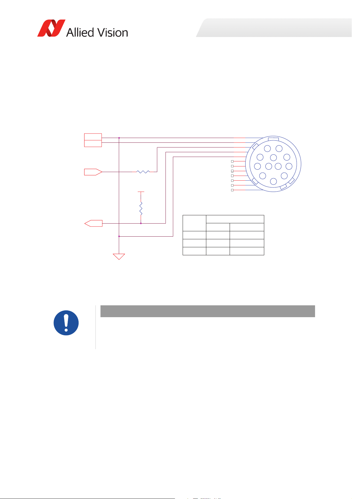
Camera trigger
R1
IN 1 (DRIVER)
USER POWER
CAMERAPOWER
OUT1 (RECEIVER)
R2
CAMERAGND
IN 1
OUT 1
ISOLATED IO GROUND
CAMERA POWER
CAMERA GND
1
2
3
4
5
6
7
8
9
10
12
HIROSE HR10A-10P-12S
1
2
3
4
5
6
7
8
9
10
11
12
CABLE SIDE
11
USER
POWER
RECOMMENDED VALUES
R1* R2
5 V 0 1 Kɏ
12 V 0.7 Kɏ 2.7 Kɏ
24 V 1.8 Kɏ 4.7 K ɏ
Camera I/O opto-isolated user circuit example
Camera interfaces
Figure 28: Prosilica GC opto-isolated user circuit
*Cameras with SN: 02-XXXXX-0XXXX, R1 necessary for input greater than 5 V.
Cameras with SN: 02-XXXXX-1XXXX, no R1 necessary, 5 to 24 V.
NOTICE
Input/Output
Input: Incoming trigger must be able to source 10 mA.
Output: User power, with pull-up resistor R2 is required.
Isolated output is connected to the open collector of Fairchild MOCD207. The
corresponding transistor emitter is connected to isolated ground. See the Fairchild
MOCD207 data sheet for more detailed information.
65Prosilica GC Technical Manual V2.4.1

Camera interfaces
CAMERA GND
1
2
3
4
5
6
7
8
9
10
12
HIROSE HR10A-10P-12S
1
2
3
4
5
6
7
8
9
10
11
12
CABLE SIDE
11
12 V POWER
IN 2
OUT 2
CAMERA GND
CAMERA POWER
IN 2 (3.3 V DRIVER)
OUT 2 (3.3 V RECEIVER)
Camera I/O non-isolated user circuit example
Figure 29: Prosilica GC non-isolated user circuit
NOTICE
Input/Output
Input: Incoming trigger must be able to source 10 µA, at 3.3 V. Input trigger voltage
greater than 5.5 V will damage the camera.
Output: The maximum sync output current is 24 mA, at 3.3 V.
The non-isolated trigger circuit is connected to a Texas Instruments SN74LVC2G241
buffer and driver inside the camera. See the Texas Instruments SN74LVC2G241 for
more detailed information.
66Prosilica GC Technical Manual V2.4.1

Trigger timing diagram
User trigger
Logic trigger
Exposure
Readout
Trigger ready
Imaging
Interline Ɵme
Idle
t
pd
Trigger
latency
Exposure
start delay
Trigger
jiƩer
Registered
exposure Ɵme
Readout Ɵme
NN+1
NN+1
Note: JiƩer at the beginning
of an exposure has no eīect
on the length of exposure.
Camera interfaces
Figure 30: Prosilica GC internal signal timing waveform
67Prosilica GC Technical Manual V2.4.1

Camera interfaces
Notes on triggering
Term Definition
User trigger Trigger signal applied by the user (hardware trigger, software trigger)
Logic trigger Trigger signal seen by the camera internal logic (not visible to the user)
Propagation delay (tpd) Propagation delay between the user trigger and the logic trigger
Exposure High when the camera image sensor is integrating light
Readout High when the camera image sensor is reading out data
Trigger latency Time delay between the user trigger and the start of exposure
Trigger jitter Deviation from the trigger latency time
Trigger ready Indicates to the user that the camera will accept the next trigger
Registered exposure time Exposure time value currently stored in the camera memory
Exposure start delay Registered exposure time subtracted from the readout time and indicates
when the next exposure cycle can begin such that the exposure will end
after the current readout
Interline time Time between sensor row readout cycles
Imaging High when the camera image sensor is either exposing and/or reading out
data
Idle High if the camera image sensor is not exposing and/or reading out data
Table 22: Explanation of signals in timing diagram
Trigger rules
User trigger pulse
The user trigger pulse width should be at least three times the width of the trigger
latency as indicated in Specifications.
• The end of exposure will always trigger the next readout.
• The end of exposure must always end after the current readout.
• The start of exposure must always correspond with the interline time if
readout is true.
• Exposure start delay equals the readout time minus the registered exposure
time.
Triggering during the idle state
For applications requiring the shortest possible Trigger Latency and the smallest
possible Trigger Jitter the User Trigger signal should be applied when Imaging is
false and Idle is true. In this case, Trigger Latency and Trigger Jitter are as indicated
in the camera Specifications section.
68Prosilica GC Technical Manual V2.4.1

Camera interfaces
i
Triggering during the readout state
For applications requiring the fastest triggering cycle time whereby the camera
image sensor is exposing and reading out simultaneously, apply the User Trigger
signal as soon as a valid Trigger Ready is detected. In this case, Trigger Latency and
Trigger Jitter can be up to 1 row time since Exposure must always begin on an
Interline boundary.
For a more detailed description of the trigger concept for advanced users and
special scenarios, see the Triggering Concept application note:
https://www.alliedvision.com/en/support/technical-papers-knowledgebase.html
69Prosilica GC Technical Manual V2.4.1

Camera interfaces
70Prosilica GC Technical Manual V2.4.1

Cleaning optical components
This chapter describes safety instructions and
cautions for cleaning lenses, optical filters, protection
glass, or sensors.
Prosilica GC Technical Manual V2.4.1 71

Warranty
i
Cleaning optical components
Important instructions to be read first
Read these instructions before you contact Allied Vision or your Allied Vision
distribution partner for assistance.
Contact Allied Vision or your Allied Vision distribution partner if you are not
familiar with the procedures described in this chapter.
Warranty information available online
For details about camera warranty duration and sensor warranty terms, go to:
https://www.alliedvision.com/en/support/warranty
Warranty precaution
To ensure your warranty remains in effect:
• Do not open the camera housing.
• Follow instructions described in this chapter.
• Use only optical quality tissue or cloth if you must clean a lens or filter.
• Use only optics cleaner. Do not use aggressive cleaners like benzine or spirit.
Such cleaners may destroy the optical component’s surface.
• Do not use compressed air which can push dust into camera and lens unless
you are trained to clean a camera using this method.
Allied Vision does not warranty against any physical damage to the sensor, filter,
protection glass, or lenses. Use utmost care when cleaning optical components.
Warranty precaution
Allied Vision does not warranty against any physical damage to the sensor, filter,
protection glass, or lenses. Use utmost care when cleaning optical components.
Keep optical components clean
The best way to ensure the camera remains clean is to avoid penetration of foreign
substances into the camera.
When screwing or unscrewing the camera lens or dust cap, hold the camera with
the mount opening towards the floor. This minimizes the possibility of any
contaminants falling on the glass surface. Always store cameras and lenses with
dust-caps on.
72Prosilica GC Technical Manual V2.4.1

Identifying impurities
If you observe any image artifacts in your video preview of your Prosilica GC
camera you may have impurities either on the lens, filter or protection glass, or on
the sensor protection glass. Every Prosilica GC camera is cleaned prior to sealing
and shipment; however, impurities may develop due to handling or unclean
environments.
As shown in figure 31, impurities (dust, particles or fluids) on the sensor or optical
components appear as a dark area, patch or spot on the image and remain fixed in
the preview window while you rotate the camera over the target.
Do not confuse this with a pixel defect which appears as a distinct point. Particles
can either rest loosely or can be more or less stuck to the optical surface.
Cleaning optical components
Figure 31: Image with tiny dust on the filter (left) and dust on the sensor (right)
Locating impurities
Before you dismount the lens you should find out if the impurity is on the filter,
lens, or sensor.
1. Start acquiring a uniform image (for example, a white sheet of paper) with the
camera.
2. To identify the affected surface, move the suspected optical component and
see if the contamination follows this movement.
a. If you move only the lens (not the camera) and the impurity moves as
well, the impurity is on the lens.
b. If you move the IR cut filter or protection glass window and the impurity
moves as well, the impurity is on the filter or protection glass. Carefully
remove the filter or protection glass and clean it on both sides using the
techniques explained in the next section. If the impurity is neither on the
lens nor the IR cut filter or protection glass, it is probably on the sensor.
Removing IR cut filter
A pin spanner wrench (Allied Vision order code: E9020001) suitable for IR filter
removal is available for purchase from Allied Vision for all Prosilica GC cameras.
NOTICE
73Prosilica GC Technical Manual V2.4.1

Cleaning optical components
Materials for cleaning optical components
Use only these cleaning materials for optical components
• Optic approved lens cotton, cloth, or tissue that is chemically pure and free
from silicones and other additives.
• Optic approved low residue cleaning liquid.
NOTICE
Never use these cleaning materials for optical components
• Dry swabs or tissue may cause scratches.
• Metal tools may cause scratches.
• Disposable cotton cosmetic swabs may contain contaminants harmful to
optical glass.
• Cosmetic cotton my cause scratches or get caught in small gaps.
• Consumer eyeglass cleaning cloths may be pretreated with silicone harmful to
optical glass.
• Aggressive cleaners like benzine, acetone, or spirits may damage the surface.
Optical cleaning liquid material safety data sheets
Read the MSDS for the optical cleaning liquid before cleaning your camera and
optics. The MSDS provides important information including hazard identification,
first aid measures, handling and storage, and PPE.
Cleaning Instructions
Workplace conditions
• Perform all cleaning operations (lenses, filter or protection glass, and sensor)
in a dust-free clean-room.
• Avoid touching the optical components with your fingers or any hard material.
• Nitrile cleanroom gloves or powder free latex gloves are recommended to
maintain low particulate levels.
• Use an ESD mat to prevent damage from an electrostatic discharge.
1. Unplug the camera from any power supply before cleaning.
74Prosilica GC Technical Manual V2.4.1
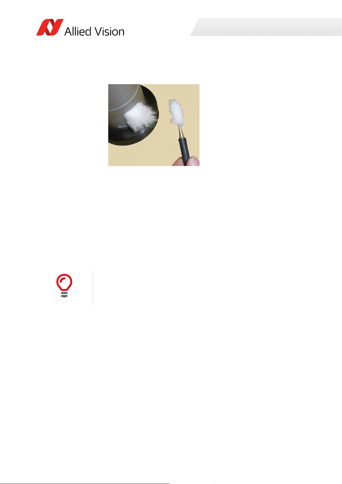
Cleaning optical components
2. Apply a small amount of cleaning liquid to a new lens cleaning cotton, cloth, or
tissue. The cotton, cloth, or lens tissue should be moist, but not dripping.
3. Hold the camera sensor diagonally upwards. Ensure that the camera is away
from your body to prevent particles like skin flakes from falling on the sensor.
4. Wipe the glass surface with a spiral motion from the center to the rim.
Normally, several spiral wipes are recommended. Wipe only on glass avoiding
contact to metal surfaces, because microscopic dirt could be released and
could cause scratches on the glass.
5. When you have finished cleaning, examine the surface in a strong light. Take
an out-of-focus picture of a flat, illuminated surface to see if any dirt or dust
remains.
6. If dust spots remain, repeat this procedure using new clean lens tissue (as
described).
Cleaning issues
If you notice that the camera lens or sensor is not clean after attempting to clean
twice, or if you have any questions regarding cleaning your camera, contact your
Allied Vision distribution partner or Allied Vision support.
75Prosilica GC Technical Manual V2.4.1

Cleaning optical components
Cleaning with compressed air
Allied Vision does not recommend cleaning Prosilica GC cameras with compressed
air.
NOTICE
Possible material damage
• Compressed air at high pressure and/or shorter operating distances may push
dust into the camera or lens and physically damage the camera, sensor, or
optical components.
• Propellant from non-optic approved compressed air products may leave a
residue on the camera or lens and may physically damage the camera, sensor,
or optical components.
• Compressed air may contain oil or moisture that could contaminate or
damage the optical components.
• Use an air blower or compressed air only if you are familiar with cleaning a
camera using this method.
If you want to clean your camera with compressed air despite of all the warnings:
• Use an optic approved compressed air product or compressor.
• Use an anti-static ionizer attachment to reduce the risk of static-caused
damage.
• Use a filter to remove moisture and oil from the air.
Use short directed bursts of air to remove impurities.
Compressed air pressure and operating distance
• Keep the compressed air pressure at a moderate strength only. Pressure at the
nozzle should be less than 1 bar (15 psi).
• Operating distance from the camera should be 5 to 30 cm.
76Prosilica GC Technical Manual V2.4.1
Firmware update
This chapter includes instructions on updating the
firmware on your Allied Vision Prosilica GC camera.
Prosilica GC Technical Manual V2.4.1 77

Firmware update
i
Download the latest GigE firmware loader from the Allied Vision website:
https://www.alliedvision.com/en/support/firmware
Saved camera user sets
If new firmware contains a new feature or control, saved camera UserSets or
ConfigFiles will be invalidated and erased!
Before loading new firmware, backup your current camera settings.
Vimba Viewer: select the Save Camera Settings icon from the Cameras window to
export the camera settings file (XML file) to the host PC.
GigE SampleViewer: select the Disk icon from the Cameras window to export
camera settings file (XML file) to the host PC.
To update the firmware on your Allied Vision GigE camera
1. Launch the Allied Vision Firmware Loader.
78Prosilica GC Technical Manual V2.4.1

Firmware update
2. Click Next. The Firmware Loader displays a list of firmware included in the
package.
3. Click Next. You can select your camera model on this page.
Recovery Mode
Select the Use recovery mode checkbox if the connected GigE camera is not found
by the firmware loader, or if the GigE camera is listed as unavailable. When
selected, power cycle the camera to enter the Boot Loader mode.
79Prosilica GC Technical Manual V2.4.1

4. Click Next.
Firmware update
5. Click Upload to start the update. The existing firmware will be erased and the
new firmware will be updated to the camera.
NOTICE
Possible material damage
Do not unplug the GigE cable or camera power supply during the update
procedure.
80Prosilica GC Technical Manual V2.4.1

Firmware update
6. The Firmware Loader will display a success status upon completion. Click Quit
to exit the loader.
Power cycle after upgrade or downgrade
You must always power cycle the camera after a firmware upgrade or downgrade.
81Prosilica GC Technical Manual V2.4.1

Appendix
The appendix includes the following information for
older Prosilica GC cameras up to serial number 0221XXA (hardware revision A):
•Specification tables
• Absolute QE plots
• ROI height vs. frame rate plots
• Camera feature comparison of hardware version
A models
• Image data flow diagrams
• Mechanical dimensions
Prosilica GC Technical Manual V2.4.1 82

Specifications common to all models
Feature Specification
Lens mount Default: C-Mount
Optional: CS-Mount
TTL (non-isolated) I/Os 1 input, 1 output
Opto-isolated I/Os 1 input, 1 output
RS232 1
Operating temperature 0 °C to +50 °C ambient temperature (without condensation)
Storage temperature -10 °C to +70 °C ambient temperature (without condensation)
Operating humidity 20% to 80% non-condensing
Power requirements 5 to 16 VDC: Cameras with SN 02-XXXXX-06000 to 02-XXXXX-07999
5 to 25 VDC: Cameras with SN ≥ 02-XXXXX-08XXX
Interface IEEE 802.3 1000BASE-T (GigE)
Interface standard GigE Vision® Standard V1.2
Camera control standard GenICam SFNC V1.2.1
Appendix
Table 23: Specifications common to all Prosilica GC models
83Prosilica GC Technical Manual V2.4.1

Prosilica GC650, GC650C (02-2110A, 022111A)
Appendix
Feature
Specification
Prosilica GC650 Prosilica GC650C
Resolution 659 (H) × 493 (V)
0.3 MP
Sensor Sony ICX424AL with HAD CCD™
technology
Sensor type Interline CCD, Progressive Scan
Shutter type Global
Sensor format Typ e 1/3
Sensor size 6 mm diagonal
Pixel size 7.4 µm × 7.4 µm
Optical filter Default: No filter
Optional: See the Modular Concept
Maximum frame rate at full
resolution
Bit depth 8-bit, 12-bit
A/D 12-bit
Image buffer 16 MB
Monochrome pixel formats Mono8, Mono12, Mono12Packed Mono8
YUV color pixels formats YUV411Packed, YUV422Packed,
RGB color pixel formats RGB8Packed, BGR8Packed
RAW pixel formats BayerRG8, BayerRG12,
Exposure time control 8 µs to 116.8 s; 1 µs increments
Gain control 0 to 19 dB
Binning (Sum) Horizontal: 1 to 8 columns
Vertical: 1 to full resolution
Power consumption 3.3 W at 12 VDC
Trigger latency 1.0 µs for non-isolated I/O; 2.8 µs for isolated I/O
Trigger j i t ter ±20 ns for non-isolated I/O; ±0.5 µs for isolated I/O
Propagation delay (tpd) 10 ns for non-isolated I/O; 1.3 µs for isolated I/O
Sony ICX424AQ with Wfine HAD
CCD™ technology
Default: IRC30 IR cut filter
Optional: See the Modular Concept
90 fps
YUV444Packed
BayerGR12Packed
Body dimensions (L × W × H) 58.7 × 45.7 × 33 mm 59 × 45.7 × 33 mm
Mass (typical) 104 g
Table 24: Prosilica GC650, GC650C model specifications
84Prosilica GC Technical Manual V2.4.1

Absolute QE
0%
10%
20%
30%
40%
50%
400 450 500 550 600 650 700 750 800 850 900 950 1000
QuantumEfficiency[%]
Wavelength[nm]
SonyICX424absoluteQE
AllmeasurementsweredonewithoutprotectionglassorIRcutfilter.
Withprotectionglassorfilters,quantumefficiency(QE)decreasesbyapproximately10%.
TheuncertaintyinmeasurementoftheQEis+/Ͳ 10.25%.
Thevaluesaretypicalandaresubjecttominorvariations.
RedQE GreenQE BlueQE MonochromeQE
0.0000
0.1000
0.2000
400 450 500 550 600 650 700 750 800 850 900 950 1000
SpectralResponse[A/W]
Wavelength[nm]
SonyICX424spectralresponse
RedResponse GreenResponse BlueResponse MonochromeResponse
Appendix
Figure 32: Prosilica GC650, GC650C (Sony ICX424) absolute QE
Spectral response
Figure 33: Prosilica GC650, GC650C (Sony ICX424) spectral response
85Prosilica GC Technical Manual V2.4.1
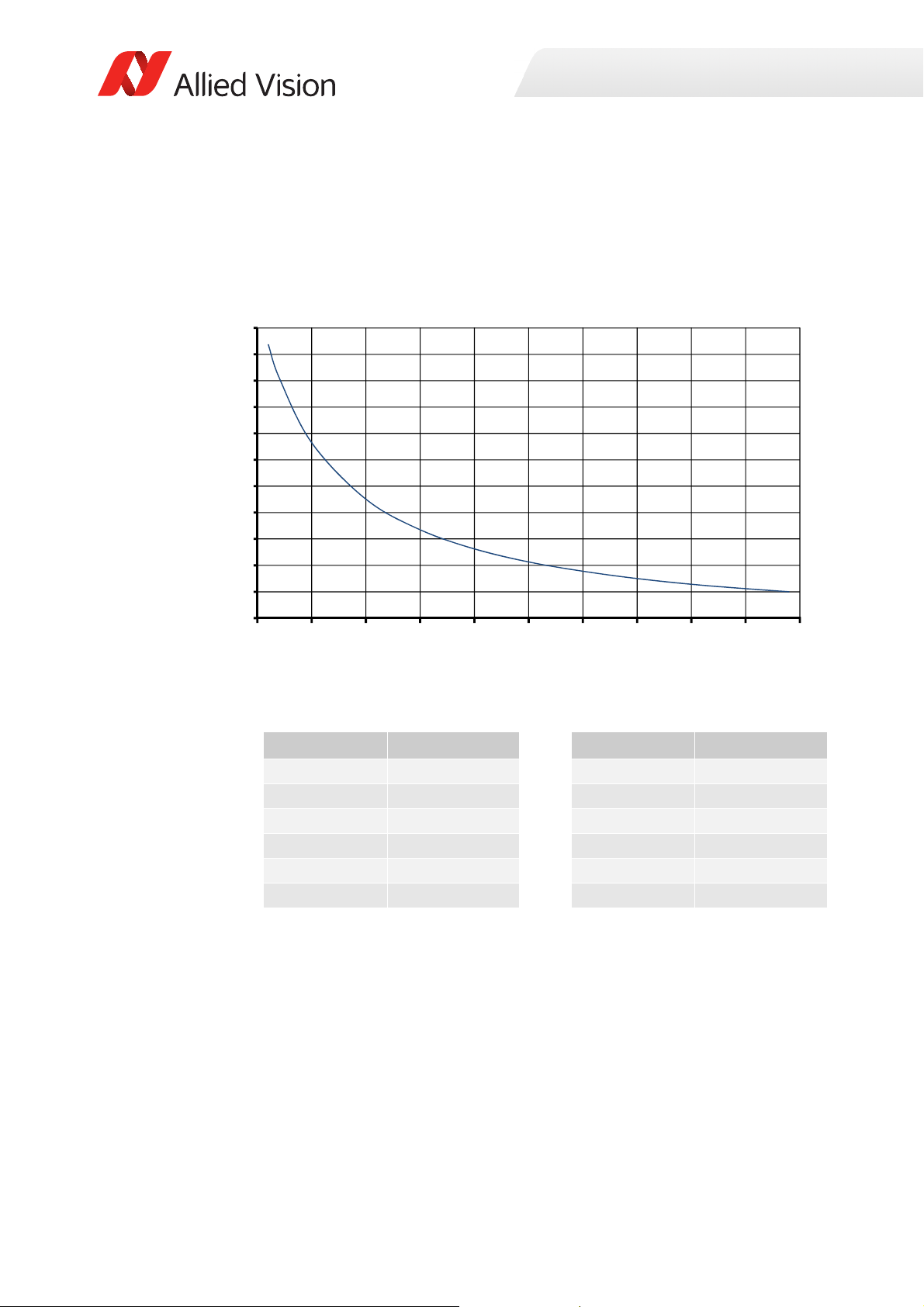
ROI frame rate
Frame rate
1
19.94 μs Height 1224.13 μs+
------------------------------------------------- ---------------------- --
=
30
90
150
210
270
330
390
450
510
570
630
690
0 50 100 150 200 250 300 350 400 450 500
Framerat e[fps]
ROIheight[pixels]
Appendix
Figure 34: Frame rate as a function of ROI height
Height (pixels) Frame rate (fps) Height (pixels) Frame rate (fps)
490 90.0 200 187.5
450 97.0 150 231.0
400 107.0 100 300.4
350 120.0 50 428.9
300 136.6 20 577.0
250 157.8 10 652.0
Width=659 pixels
Table 25: Frame rate as a function of ROI height
86Prosilica GC Technical Manual V2.4.1

Prosilica GC655, GC655C (02-2115A, 022116A)
Appendix
Feature
Specification
Prosilica GC655 Prosilica GC655C
Resolution 659 (H) × 493 (V)
0.3 MP
Sensor Sony ICX414AL with HAD technology Sony ICX414AQ with Wfine HAD
CCD™ technology
Sensor type Interline CCD, Progressive Scan
Shutter type Global
Sensor format Typ e 1/2
Sensor size 8.0 mm diagonal
Pixel size 9.9 μm × 9.9 μm
Optical filter Default: No filter
Optional: See the Modular Concept
Maximum frame rate at full
resolution
Bit depth 8-bit, 12-bit
A/D 12-bit
Image buffer 16 MB
Monochrome pixel formats Mono8, Mono12, Mono12Packed Mono8
YUV color pixels formats YUV411Packed, YUV422Packed,
RGB color pixel formats RGB8Packed, BGR8Packed
RAW pixel formats BayerRG8, BayerRG12,
Exposure time control 8 µs to 116.8 s; 1 µs increments
Gain control 0 to 22 dB
Binning (Sum) Horizontal: 1 to 8 columns
Vertical: 1 to full resolution
Power consumption 3.0 W at 12 VDC
Trigger latency 1.0 µs for non-isolated I/O; 2.8 µs for isolated I/O
Trigger j i t ter ±20 ns for non-isolated I/O; ±0.5 µs for isolated I/O
Propagation delay (tpd) 10 ns for non-isolated I/O; 1.3 µs for isolated I/O
Default: IRC30 IR cut filter
Optional: See the Modular Concept
90 fps
YUV444Packed
BayerGR12Packed
Body dimensions (L × W × H) 58.7 × 45.7 × 33 mm 59 × 45.7 × 33 mm
Mass (typical) 105 g
Table 26: Prosilica GC655, GC655C model specifications
87Prosilica GC Technical Manual V2.4.1

Absolute QE
0%
10%
20%
30%
40%
50%
400 450 500 550 600 650 700 750 800 850 900 950 1000
QuantumEfficiency[%]
Wavelength[nm]
SonyICX414absoluteQE
AllmeasurementsweredonewithoutprotectionglassorIRcutfilter.
Withprotectionglassorfilters,quantumefficiency(QE)decreasesbyapproximately10%.
TheuncertaintyinmeasurementoftheQEis+/Ͳ 10.25%.
Thevaluesaretypicalandaresubjecttominorvariations.
RedQE GreenQE BlueQE MonochromeQE
0.0000
0.1000
0.2000
400 450 500 550 600 650 700 750 800 850 900 950 1000
SpectralResponse[A/W]
Wavelength[nm]
SonyICX414spectralresponse
RedResponse GreenResponse BlueResponse MonochromeResponse
Appendix
Figure 35: Prosilica GC655, GC655C (Sony ICX414) absolute QE
Spectral response
Figure 36: Prosilica GC655, GC655C (Sony ICX414) spectral response
88Prosilica GC Technical Manual V2.4.1

ROI frame rate
Frame rate
1
19.94 μs Height 1224.14 μs+
----------------------------------------------------- --------------------
=
30
90
150
210
270
330
390
450
510
570
630
690
0 50 100 150 200 250 300 350 400 450 500
Framerate[fps]
ROIheight[pixels]
Appendix
Figure 37: Frame rate as a function of ROI height
Height (pixels) Frame rate (fps) Height (pixels) Frame rate (fps)
490 90.0 200 187.5
450 97.0 150 231.0
400 107.2 100 300.4
350 120.1 50 428.9
300 136.6 20 577.0
250 157.8 10 652.0
Width=659 pixels
Table 27: Frame rate as a function of ROI height
89Prosilica GC Technical Manual V2.4.1

Prosilica GC750, GC750C (02-2160A, 022161A)
Appendix
Feature
Resolution 752 (H) × 480 (V)
Sensor ON Semi MT9V022
Sensor type CMOS
Shutter type Global
Sensor format Typ e 1/3
Sensor size 5.35 mm diagonal
Pixel size 6 μm × 6 μm
Optical filter Default: No filter
Optional: See the Modular Concept
Maximum frame rate at full
resolution
Bit depth 8-bit, 10-bit
A/D 10-bit
Image buffer 16 MB
Monochrome pixel formats Mono8, Mono10 Mono8
YUV color pixels formats YUV411Packed, YUV422Packed,
RGB color pixel formats RGB8Packed, BGR8Packed,
RAW pixel formats BayerBG8, BayerBG10
Exposure time control 30 µs to 60 s; 1 µs increments
Gain control 0 to 48 dB
Power consumption 2.2 W at 12 VDC
Trigger latency 31 μs for non-isolated I/O; 43 μs for isolated I/O
Trigger j i t ter ±20 ns for non-isolated I/O; ±0.5 µs for isolated I/O
Propagation delay (tpd) 10 ns for non-isolated I/O; 1.3 µs for isolated I/O
Body dimensions (L × W × H) 50.6 × 45.7 × 33 mm 50.9 × 45.7 × 33 mm
Mass (typical) 85 g
Prosilica GC750 Prosilica GC750C
0.4 MP
Default: IRC30 IR cut filter
Optional: See the Modular Concept
67 fps
YUV444Packed
RGBA8Packed, BGRA8Packed
Specification
Table 28: Prosilica GC750, GC750C model specifications
90Prosilica GC Technical Manual V2.4.1

Absolute QE
0%
10%
20%
30%
40%
50%
60%
Quantum ĸĐŝĞnĐy
tĂǀĞlĞngth [nm]
400 500 600 700 800 900 1000
0%
5%
10%
15%
20%
25%
30%
35%
Quantum ĸĐŝĞnĐy
tĂǀĞlĞngth [nm]
Red Green Blue
400 450 500 550 600 650 700
Appendix
Figure 38: Prosilica GC750 (ON Semi MT9V022) absolute QE
Figure 39: Prosilica GC750C (ON Semi MT9V022) absolute QE
91Prosilica GC Technical Manual V2.4.1

ROI frame rate
0
100
200
300
400
500
600
700
800
900
0 50 100 150 200 250 300 350 400 450 500
Framerate[fps]
ROIheight[pixels]
Appendix
Figure 40: Frame rate as a function of ROI height
Height (pixels) Frame rate (fps) Height (pixels) Frame rate (fps)
480 62.9 100 238.0
400 75.3 50 371.7
300 97.6 20 560.6
250 114.5 10 674.9
200 138.4 2 806.4
150 175.1
Width=752 pixels
Table 29: Frame rate as a function of ROI height
92Prosilica GC Technical Manual V2.4.1

Prosilica GC780, GC780C (02-2117A, 022118A)
Appendix
Feature
Resolution 782 (H) × 582 (V)
Sensor Sony ICX415AL with HAD technology Sony ICX415AQ with Wfine HAD
Sensor type Interline CCD, Progressive Scan
Shutter type Global
Sensor format Typ e 1/2
Sensor size 8.0 mm diagonal
Pixel size 8.3 μm × 8.3 μm
Optical filter Default: No filter
Optional: See the Modular Concept
Maximum frame rate at full
resolution
Bit depth 8-bit, 12-bit
A/D 12-bit
Image buffer 16 MB
Monochrome pixel formats Mono8, Mono12, Mono12Packed Mono8
YUV color pixels formats YUV411Packed, YUV422Packed,
RGB color pixel formats RGB8Packed, BGR8Packed
RAW pixel formats BayerRG8, BayerRG12,
Exposure time control 8 µs to 116.8 s; 1 µs increments
Binning (Sum) Horizontal: 1 to 8 columns
Gain control 0 to 26 dB 0 to 23 dB
Power consumption 2.8 W at 12 VDC
Trigger latency 1 μs for non-isolated I/O; 2.8 μs for isolated I/O
Trigger j i t ter ±20 ns for non-isolated I/O; ±0.5 µs for isolated I/O
Propagation delay (tpd) 10 ns for non-isolated I/O; 1.3 μs for isolated I/O
Body dimensions (L × W × H) 58.7 × 45.7 × 33 mm 59 × 45.7 × 33 mm
Mass (typical) 100 g
Prosilica GC780 Prosilica GC780C
Specification
0.5 MP
CCD™ technology
Default: IRC30 IR cut filter
Optional: See the Modular Concept
63.9 fps
YUV444Packed
BayerGR12Packed
Vertical: 1 to full resolution
Table 30: Prosilica GC780, GC780C model specifications
93Prosilica GC Technical Manual V2.4.1

Absolute QE
0%
10%
20%
30%
40%
50%
400 450 500 550 600 650 700 750 800 850 900 950 1000
QuantumEfficiency[%]
Wavelength[nm]
SonyICX415absoluteQE
AllmeasurementsweredonewithoutprotectionglassorIRcutfilter.
Withprotectionglassorfilters,quantumefficiency(QE)decreasesbyapproximately10%.
TheuncertaintyinmeasurementoftheQEis+/Ͳ 10.25%.
Thevaluesaretypicalandaresubjecttominorvariations.
RedQE GreenQE BlueQE MonochromeQE
0.0000
0.1000
0.2000
400 450 500 550 600 650 700 750 800 850 900 950 1000
SpectralResponse[A/W]
Wavelength[nm]
SonyICX415spectralresponse
RedResponse GreeenResponse BlueResponse MonochromeResponse
Appendix
Figure 41: Prosilica GC780, GC780C (Sony ICX415) absolute QE
Spectral response
Figure 42: Prosilica GC780, GC780C (Sony ICX415) spectral response
94Prosilica GC Technical Manual V2.4.1
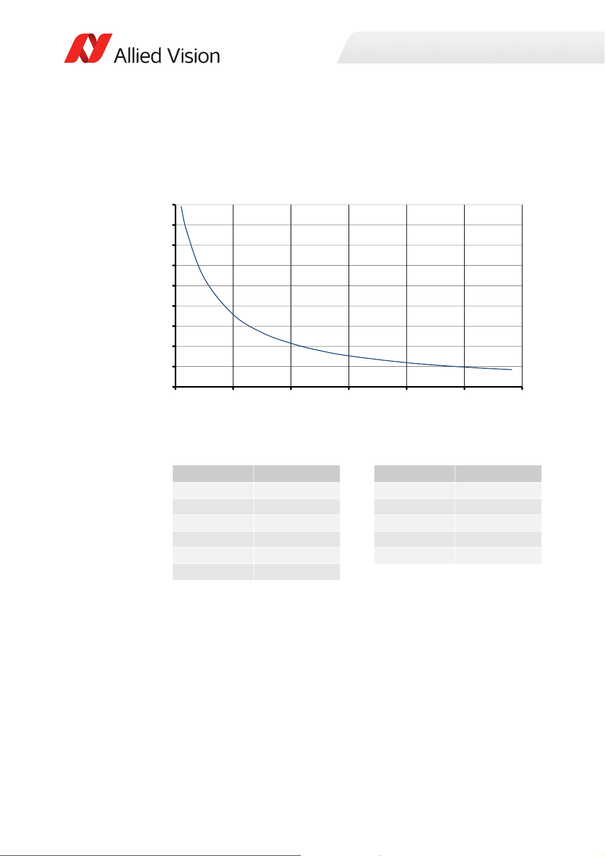
ROI frame rate
Frame rate
1
24.70 μs Height 1139.14 μs+
----------------------------------------------------- --------------------
=
0
75
150
225
300
375
450
525
600
675
0 100 200 300 400 500 600
Framerate[fps]
ROIheight[pixels]
Appendix
Figure 43: Frame rate as a function of ROI height
Height (pixels) Frame rate (fps) Height (pixels) Frame rate (fps)
582 63.9 150 201.1
500 73.4 100 268.1
400 89.8 50 402.6
300 115.2 20 573.8
250 134.5 10 668.6
200 161.5
Width=782 pixels
Table 31: Frame rate as a function of ROI height
95Prosilica GC Technical Manual V2.4.1

Prosilica GC1020, GC1020C (02-2165A, 022165B, 02-2166A, 02-2166B)
Appendix
Feature
Resolution 1024 (H) × 768 (V)
Sensor Sony ICX204AL with HAD technology Sony ICX204AK with Wfine HAD
Sensor type Interline CCD, Progressive Scan
Shutter type Global
Sensor size Typ e 1/3
Sensor size 6.0 mm diagonal
Pixel size 4.65 μm × 4.65 μm
Optical filter Default: No filter
Optional: See the Modular Concept
Maximum frame rate at full
resolution
Bit depth 8-bit, 12-bit
A/D 12-bit
Image buffer 16 MB
Monochrome pixel formats Mono8, Mono12, Mono12Packed Mono8
YUV color pixels formats YUV411Packed, YUV422Packed,
RGB color pixel formats RGB8Packed, BGR8Packed
RAW pixel formats BayerRG8, BayerRG12,
Exposure time control 8 µs to 116.8 s; 1 µs increments
Gain control 0 to 22 dB
Binning (Sum) Horizontal: 1 to 8 columns
Opto-coupled I/Os 1 input, 1 output
Power consumption 2.9 W at 12 VDC
Trigger latency 2.8 µs for non-isolated I/O; 4.5 µs for isolated I/O
Trigger j i t ter ±20 ns for non-isolated I/O; ±0.5 µs for isolated I/O
Propagation delay (tpd) 10 ns for non-isolated I/O; 1.3 μs for isolated I/O
Body dimensions (L × W × H) 58.7 × 45.7 × 33 mm 59 × 45.7 × 33 mm
Mass (typical) 99 g
Prosilica GC1020 Prosilica GC1020C
0.8 MP
CCD™ technology
Default: IRC30 IR cut filter
Optional: See the Modular Concept
33 fps
YUV444Packed
BayerGR12Packed
Vertical: 1 to full resolution
Specification
Table 32: Prosilica GC1020, GC1020C model specifications
96Prosilica GC Technical Manual V2.4.1

Absolute QE
0%
10%
20%
30%
40%
50%
400 450 500 550 600 650 700 750 800 850 900 950 1000
QuantumEfficiency[%]
Wavelength[nm]
SonyICX204absoluteQE
AllmeasurementsweredonewithoutprotectionglassorIRcutfilter.
Withprotectionglassorfilters,quantumefficiency(QE)decreasesbyapproximately10%.
TheuncertaintyinmeasurementoftheQEis+/Ͳ 10.25%.
Thevaluesaretypicalandaresubjecttominorvariations.
RedQE GreenQE BlueQE MonochromeQE
0.0000
0.1000
0.2000
400 450 500 550 600 650 700 750 800 850 900 950 1000
SpectralResponse[A/W]
Wavel ength[nm]
SonyICX204spectralresponse
RedResponse GreenResponse BlueResponse MonochromeResponse
Appendix
Figure 44: Prosilica GC1020, GC1020C (Sony ICX204) absolute QE
Spectral response
Figure 45: Prosilica GC1020, GC1020C (Sony ICX204) spectral response
97Prosilica GC Technical Manual V2.4.1
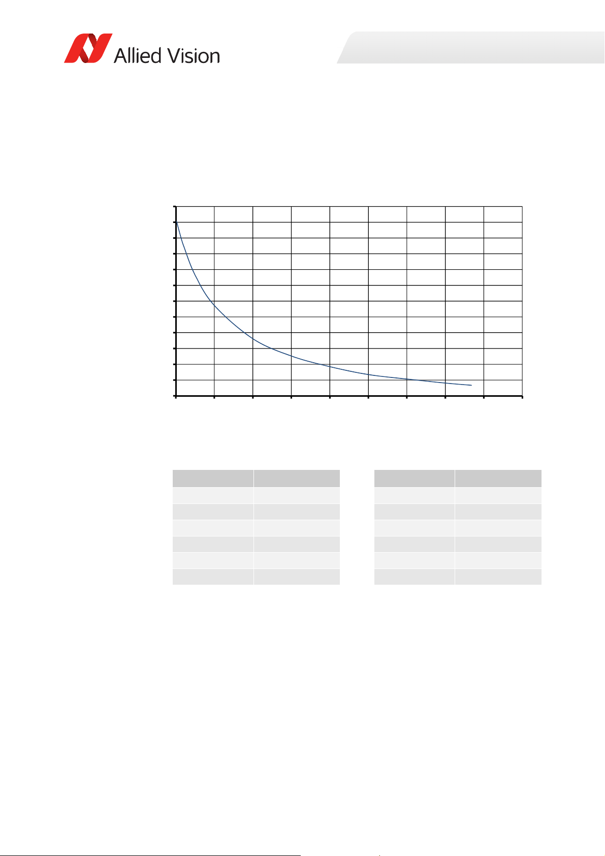
ROI frame rate
Frame rate
1
33.56 μs Height 3971.23 μs+
----------------------------------------------------- --------------------
=
20
40
60
80
100
120
140
160
180
200
220
240
260
0 100 200 300 400 500 600 700 800 900
Framerate[fps]
ROIheight[pixels]
Appendix
Figure 46: Frame rate as a function of ROI height
Height (pixels) Frame rate (fps) Height (pixels) Frame rate (fps)
768 33.4 200 92.4
700 36.2 100 134.5
600 41.3 50 173.0
500 47.0 20 210.3
400 57.0 10 226.3
300 70.5 2 241.0
Width=1024 pixels
Table 33: Frame rate as a function of ROI height
98Prosilica GC Technical Manual V2.4.1

Prosilica GC1350, GC1350C (02-2130A, 022131A)
Appendix
Feature
Resolution 1360 (H) × 1024 (V)
Sensor Sony ICX205AL with HAD technology Sony ICX205AK with Wfine HAD
Sensor type Interline CCD, Progressive Scan
Shutter type Global
Sensor format Typ e 1/2
Sensor size 8.0 mm diagonal
Pixel size 4.65 μm × 4.65 μm
Optical filter Default: No filter
Optional: See the Modular Concept
Maximum frame rate at full
resolution
A/D 12-bit
Image buffer 16 MB
Bit depth 8-bit, 12-bit
Monochrome pixel formats Mono8, Mono12, Mono12Packed Mono8
YUV color pixels formats YUV411Packed, YUV422Packed,
RGB color pixel formats RGB8Packed, BGR8Packed
RAW pixel formats BayerRG8, BayerRG12,
Exposure time control 8 µs to 116.8 s; 1 µs increments
Gain control 0 to 25 dB
Binning (Sum) Horizontal: 1 to 8 columns
Power consumption 3 W at 12 VDC
Trigger latency 3.5 µs for non-isolated I/O; 5 µs for isolated I/O
Trigger j i t ter ±20 ns for non-isolated I/O; ±0.5 µs for isolated I/O
Propagation delay (tpd) 10 ns for non-isolated I/O; 1.3 μs for isolated I/O
Body dimensions (L × W × H) 58.7 × 45.7 × 33 mm 59 × 45.7 × 33 mm
Mass (typical) 100 g
Prosilica GC1350 Prosilica GC1350C
1.4 MP
CCD™ technology
Default: IRC30 IR cut filter
Optional: See the Modular Concept
20 fps
YUV444Packed
BayerGR12Packed
Vertical: 1 to full resolution
Specification
Table 34: Prosilica GC1350, GC1350C model specifications
99Prosilica GC Technical Manual V2.4.1

Absolute QE
0%
5%
10%
15%
20%
25%
30%
35%
40%
45%
Quantum ĸĐŝĞnĐy
tĂǀĞlĞngth [nm]
400 500 600 700 800 900 1000
0%
5%
10%
15%
20%
25%
30%
35%
40%
Quantum ĸĐŝĞnĐy
tĂǀĞlĞngth [nm]
Red Green Blue
400 450 500 550 600 650 700
Appendix
Figure 47: Prosilica GC1350 (Sony ICX205) absolute QE
Figure 48: Prosilica GC1350C (Sony ICX205) absolute QE
100Prosilica GC Technical Manual V2.4.1
 Loading...