

Allied Vision Goldeye CL-008 Cool TEC1, Goldeye CL-033 TEC1, Goldeye CL-032 Cool TEC2, Goldeye CL-032 TEC1, Goldeye G-008 TEC1 Technical Manual
...
GIGE VISION & CAMERA LINK SWIR CAMERAS
Goldeye G/CL
Technical Manual
V4.1.1
Allied Vision Technologies GmbH // Taschenweg 2a, 07646 Stadtroda/Germany 2018-Jun-26

Goldeye G/CL at a glance
Contents of your delivery
Your Goldeye delivery consists of the following items:
Shipping box
Camera Goldeye
Goldeye G/CL at a glance
Installation Guide
What else do you need?
The references below provide additional documentation and software.
Documents Where to find it
Goldeye G/CL
Features reference
Software Where to find it
Vimba https://www.alliedvision.com/en/products/
Accessories Where to find it
Power supply,
I/O connector,
Ethernet adaptors,
Camera Link cables
https://www.alliedvision.com/fileadmin/content/
documents/products/cameras/various/features/
Goldeye_GigE_CL_Features_Reference.pdf
software.html
You find all accessories necessary to run the camera in
Adapters and connectors on page 120.
2Goldeye G/CL Technical Manual V4.1.1

Goldeye G/CL at a glance
Contact Allied Vision
Website
To contact Allied Vision with any inquiry, go to:
https://www.alliedvision.com/en/meta-header/contact
To find an Allied Vision office or distribution partner, go to:
https://www.alliedvision.com/en/about-us/where-we-are
Telephone, Fax & Email
For all camera-related queries contact us at support@alliedvision.com
For all general inquiries, contact us at info@alliedvision.com
North and South America
Toll-free// +1-877-USA-1394
T// +1 978 225 2030
Europe, Middle East, and Africa
Allied Vision
T// +49 36428 677-0 (Reception)
T// +49 36428 677-230 (Sales)
F// +49 36428 677-28
Asia-Pacific
Allied Vision
T// +65 6634 9027
Sales Office China
T// +86 21 64861133
3Goldeye G/CL Technical Manual V4.1.1

Table of contents
Table of contents
Goldeye G/CL at a glance 2
Contents of your delivery. . . . . . . . . . . . . . . . . . . . . . . . . . . . . . . . . . . . . . . . . . . . . . . . . . . . . . . . . . . . . . . . . 2
What else do you need?. . . . . . . . . . . . . . . . . . . . . . . . . . . . . . . . . . . . . . . . . . . . . . . . . . . . . . . . . . . . . . . . . . 2
Contact Allied Vision. . . . . . . . . . . . . . . . . . . . . . . . . . . . . . . . . . . . . . . . . . . . . . . . . . . . . . . . . . . . . . . . . . . . . 3
Table of contents 4
Document history and conventions 10
Document history . . . . . . . . . . . . . . . . . . . . . . . . . . . . . . . . . . . . . . . . . . . . . . . . . . . . . . . . . . . . . . . . . . . . 11
Conventions used in this manual. . . . . . . . . . . . . . . . . . . . . . . . . . . . . . . . . . . . . . . . . . . . . . . . . . . . . . . . . . 13
Compliance, safety, and intended use 14
Compliance notifications . . . . . . . . . . . . . . . . . . . . . . . . . . . . . . . . . . . . . . . . . . . . . . . . . . . . . . . . . . . . . . . . . . . 15
For customers in Europe . . . . . . . . . . . . . . . . . . . . . . . . . . . . . . . . . . . . . . . . . . . . . . . . . . . . . . . . . . . . . . . 15
For customers in the USA . . . . . . . . . . . . . . . . . . . . . . . . . . . . . . . . . . . . . . . . . . . . . . . . . . . . . . . . . . . . . . 15
Camera applications and intended use . . . . . . . . . . . . . . . . . . . . . . . . . . . . . . . . . . . . . . . . . . . . . . . . . . . . . . . . 16
General use . . . . . . . . . . . . . . . . . . . . . . . . . . . . . . . . . . . . . . . . . . . . . . . . . . . . . . . . . . . . . . . . . . . . . . . . . . . 16
Use in medical devices . . . . . . . . . . . . . . . . . . . . . . . . . . . . . . . . . . . . . . . . . . . . . . . . . . . . . . . . . . . . . . . . . . 16
Copyright and trademarks . . . . . . . . . . . . . . . . . . . . . . . . . . . . . . . . . . . . . . . . . . . . . . . . . . . . . . . . . . . . . . . 16
Installation and hardware GigE 17
Getting started . . . . . . . . . . . . . . . . . . . . . . . . . . . . . . . . . . . . . . . . . . . . . . . . . . . . . . . . . . . . . . . . . . . . . . . . . . . 18
Optics . . . . . . . . . . . . . . . . . . . . . . . . . . . . . . . . . . . . . . . . . . . . . . . . . . . . . . . . . . . . . . . . . . . . . . . . . . . . . . . . 18
GigE Vision software. . . . . . . . . . . . . . . . . . . . . . . . . . . . . . . . . . . . . . . . . . . . . . . . . . . . . . . . . . . . . . . . . . . . 18
Overview of installation . . . . . . . . . . . . . . . . . . . . . . . . . . . . . . . . . . . . . . . . . . . . . . . . . . . . . . . . . . . . . . . . . 19
Mounting the camera . . . . . . . . . . . . . . . . . . . . . . . . . . . . . . . . . . . . . . . . . . . . . . . . . . . . . . . . . . . . . . . . . . . . . . 20
Configuring the host computer . . . . . . . . . . . . . . . . . . . . . . . . . . . . . . . . . . . . . . . . . . . . . . . . . . . . . . . . . . . . . . 21
Installing the Ethernet adapter driver. . . . . . . . . . . . . . . . . . . . . . . . . . . . . . . . . . . . . . . . . . . . . . . . . . . . . . 21
Updating the driver manually . . . . . . . . . . . . . . . . . . . . . . . . . . . . . . . . . . . . . . . . . . . . . . . . . . . . . . . . . 21
Modifying Ethernet adapter IP address . . . . . . . . . . . . . . . . . . . . . . . . . . . . . . . . . . . . . . . . . . . . . . . . . . . . 22
Optimizing the Ethernet adapter . . . . . . . . . . . . . . . . . . . . . . . . . . . . . . . . . . . . . . . . . . . . . . . . . . . . . . . . . 22
Jumbo packets . . . . . . . . . . . . . . . . . . . . . . . . . . . . . . . . . . . . . . . . . . . . . . . . . . . . . . . . . . . . . . . . . . . . . 23
Installing viewer software . . . . . . . . . . . . . . . . . . . . . . . . . . . . . . . . . . . . . . . . . . . . . . . . . . . . . . . . . . . . . . . 23
Allied Vision software . . . . . . . . . . . . . . . . . . . . . . . . . . . . . . . . . . . . . . . . . . . . . . . . . . . . . . . . . . . . . . . 23
Vimba Viewer documentation . . . . . . . . . . . . . . . . . . . . . . . . . . . . . . . . . . . . . . . . . . . . . . . . . . . . . . . . 24
Third-party software . . . . . . . . . . . . . . . . . . . . . . . . . . . . . . . . . . . . . . . . . . . . . . . . . . . . . . . . . . . . . . . . 24
Connecting your camera. . . . . . . . . . . . . . . . . . . . . . . . . . . . . . . . . . . . . . . . . . . . . . . . . . . . . . . . . . . . . . . . . . . . 25
Accessories . . . . . . . . . . . . . . . . . . . . . . . . . . . . . . . . . . . . . . . . . . . . . . . . . . . . . . . . . . . . . . . . . . . . . . . . . . . 25
Camera drivers . . . . . . . . . . . . . . . . . . . . . . . . . . . . . . . . . . . . . . . . . . . . . . . . . . . . . . . . . . . . . . . . . . . . . . . . 25
Powering up the camera . . . . . . . . . . . . . . . . . . . . . . . . . . . . . . . . . . . . . . . . . . . . . . . . . . . . . . . . . . . . . . . . 25
Connecting to host application . . . . . . . . . . . . . . . . . . . . . . . . . . . . . . . . . . . . . . . . . . . . . . . . . . . . . . . . . . . . . . 26
Launch the application . . . . . . . . . . . . . . . . . . . . . . . . . . . . . . . . . . . . . . . . . . . . . . . . . . . . . . . . . . . . . . . . . . 26
4Goldeye G/CL Technical Manual V4.1.1

Table of contents
Grabbing images . . . . . . . . . . . . . . . . . . . . . . . . . . . . . . . . . . . . . . . . . . . . . . . . . . . . . . . . . . . . . . . . . . . . . . . 27
Installation and hardware CL 28
Getting started . . . . . . . . . . . . . . . . . . . . . . . . . . . . . . . . . . . . . . . . . . . . . . . . . . . . . . . . . . . . . . . . . . . . . . . . . . . 29
Optics . . . . . . . . . . . . . . . . . . . . . . . . . . . . . . . . . . . . . . . . . . . . . . . . . . . . . . . . . . . . . . . . . . . . . . . . . . . . . . . . 29
Frame grabber. . . . . . . . . . . . . . . . . . . . . . . . . . . . . . . . . . . . . . . . . . . . . . . . . . . . . . . . . . . . . . . . . . . . . . . . . 29
Cables . . . . . . . . . . . . . . . . . . . . . . . . . . . . . . . . . . . . . . . . . . . . . . . . . . . . . . . . . . . . . . . . . . . . . . . . . . . . . . . 30
Allied Vision software . . . . . . . . . . . . . . . . . . . . . . . . . . . . . . . . . . . . . . . . . . . . . . . . . . . . . . . . . . . . . . . . . . . 30
Overview of installation . . . . . . . . . . . . . . . . . . . . . . . . . . . . . . . . . . . . . . . . . . . . . . . . . . . . . . . . . . . . . . . . . 30
Mounting the camera . . . . . . . . . . . . . . . . . . . . . . . . . . . . . . . . . . . . . . . . . . . . . . . . . . . . . . . . . . . . . . . . . . . . . . 31
Installing hardware and software . . . . . . . . . . . . . . . . . . . . . . . . . . . . . . . . . . . . . . . . . . . . . . . . . . . . . . . . . . . . 32
Installing a frame grabber . . . . . . . . . . . . . . . . . . . . . . . . . . . . . . . . . . . . . . . . . . . . . . . . . . . . . . . . . . . . . . . 32
Installing camera software. . . . . . . . . . . . . . . . . . . . . . . . . . . . . . . . . . . . . . . . . . . . . . . . . . . . . . . . . . . . . . . 32
Installing Vimba Viewer on Windows . . . . . . . . . . . . . . . . . . . . . . . . . . . . . . . . . . . . . . . . . . . . . . . . . . . 33
Installing the Vimba Viewer on Linux . . . . . . . . . . . . . . . . . . . . . . . . . . . . . . . . . . . . . . . . . . . . . . . . . . . 33
Starting the camera. . . . . . . . . . . . . . . . . . . . . . . . . . . . . . . . . . . . . . . . . . . . . . . . . . . . . . . . . . . . . . . . . . . . . . . . 34
Powering up the camera . . . . . . . . . . . . . . . . . . . . . . . . . . . . . . . . . . . . . . . . . . . . . . . . . . . . . . . . . . . . . . . . 34
Connecting to host computer . . . . . . . . . . . . . . . . . . . . . . . . . . . . . . . . . . . . . . . . . . . . . . . . . . . . . . . . . . . . 34
Camera control and image viewing . . . . . . . . . . . . . . . . . . . . . . . . . . . . . . . . . . . . . . . . . . . . . . . . . . . . . . . . . . . 35
Vimba with frame grabber specific viewer. . . . . . . . . . . . . . . . . . . . . . . . . . . . . . . . . . . . . . . . . . . . . . . . . . 35
Overview . . . . . . . . . . . . . . . . . . . . . . . . . . . . . . . . . . . . . . . . . . . . . . . . . . . . . . . . . . . . . . . . . . . . . . . . . . 35
Adjusting the transfer speed for your frame grabber. . . . . . . . . . . . . . . . . . . . . . . . . . . . . . . . . . . . . . 35
Launch the applications. . . . . . . . . . . . . . . . . . . . . . . . . . . . . . . . . . . . . . . . . . . . . . . . . . . . . . . . . . . . . . 36
Adjust camera controls: Controller window . . . . . . . . . . . . . . . . . . . . . . . . . . . . . . . . . . . . . . . . . . . . . 39
Grabbing images. . . . . . . . . . . . . . . . . . . . . . . . . . . . . . . . . . . . . . . . . . . . . . . . . . . . . . . . . . . . . . . . . . . . 39
Camera information: Information window . . . . . . . . . . . . . . . . . . . . . . . . . . . . . . . . . . . . . . . . . . . . . . 40
Using a custom application . . . . . . . . . . . . . . . . . . . . . . . . . . . . . . . . . . . . . . . . . . . . . . . . . . . . . . . . . . . . . . 41
Using frame grabber transport layer. . . . . . . . . . . . . . . . . . . . . . . . . . . . . . . . . . . . . . . . . . . . . . . . . . . . . . . 41
Troubleshooting . . . . . . . . . . . . . . . . . . . . . . . . . . . . . . . . . . . . . . . . . . . . . . . . . . . . . . . . . . . . . . . . . . . . . . . . . . 43
Helpful hints . . . . . . . . . . . . . . . . . . . . . . . . . . . . . . . . . . . . . . . . . . . . . . . . . . . . . . . . . . . . . . . . . . . . . . . . . . 43
Is the camera getting power? . . . . . . . . . . . . . . . . . . . . . . . . . . . . . . . . . . . . . . . . . . . . . . . . . . . . . . . . . 43
Is the camera powered, but not detected in viewer?. . . . . . . . . . . . . . . . . . . . . . . . . . . . . . . . . . . . . . 43
Is the camera listed in viewer, but images cannot be acquired?. . . . . . . . . . . . . . . . . . . . . . . . . . . . . 43
Additional references . . . . . . . . . . . . . . . . . . . . . . . . . . . . . . . . . . . . . . . . . . . . . . . . . . . . . . . . . . . . . . . . . . 44
Specifications 45
Technical overview . . . . . . . . . . . . . . . . . . . . . . . . . . . . . . . . . . . . . . . . . . . . . . . . . . . . . . . . . . . . . . . . . . . . . . . . 46
Advanced features . . . . . . . . . . . . . . . . . . . . . . . . . . . . . . . . . . . . . . . . . . . . . . . . . . . . . . . . . . . . . . . . . . . . . 46
Framerates and cooling . . . . . . . . . . . . . . . . . . . . . . . . . . . . . . . . . . . . . . . . . . . . . . . . . . . . . . . . . . . . . . . . . 47
Models and modular options . . . . . . . . . . . . . . . . . . . . . . . . . . . . . . . . . . . . . . . . . . . . . . . . . . . . . . . . . . . . 47
Model naming . . . . . . . . . . . . . . . . . . . . . . . . . . . . . . . . . . . . . . . . . . . . . . . . . . . . . . . . . . . . . . . . . . . . . . . . . 48
Name affix for temperature control . . . . . . . . . . . . . . . . . . . . . . . . . . . . . . . . . . . . . . . . . . . . . . . . . . . . 48
Name affix for housing size . . . . . . . . . . . . . . . . . . . . . . . . . . . . . . . . . . . . . . . . . . . . . . . . . . . . . . . . . . . 49
Technical specifications . . . . . . . . . . . . . . . . . . . . . . . . . . . . . . . . . . . . . . . . . . . . . . . . . . . . . . . . . . . . . . . . . . . . 50
Goldeye CL-008 SWIR TEC1 . . . . . . . . . . . . . . . . . . . . . . . . . . . . . . . . . . . . . . . . . . . . . . . . . . . . . . . . . . . . . . 50
Absolute quantum efficiency . . . . . . . . . . . . . . . . . . . . . . . . . . . . . . . . . . . . . . . . . . . . . . . . . . . . . . . . . 53
Resolution and ROI frame rates . . . . . . . . . . . . . . . . . . . . . . . . . . . . . . . . . . . . . . . . . . . . . . . . . . . . . . . 53
Goldeye CL-008 SWIR Cool TEC1 . . . . . . . . . . . . . . . . . . . . . . . . . . . . . . . . . . . . . . . . . . . . . . . . . . . . . . . . . . 55
5Goldeye G/CL Technical Manual V4.1.1

Table of contents
Absolute quantum efficiency . . . . . . . . . . . . . . . . . . . . . . . . . . . . . . . . . . . . . . . . . . . . . . . . . . . . . . . . 57
Resolution and ROI frame rates . . . . . . . . . . . . . . . . . . . . . . . . . . . . . . . . . . . . . . . . . . . . . . . . . . . . . . . 58
Goldeye CL-032 SWIR TEC1 . . . . . . . . . . . . . . . . . . . . . . . . . . . . . . . . . . . . . . . . . . . . . . . . . . . . . . . . . . . . . . 60
Absolute quantum efficiency . . . . . . . . . . . . . . . . . . . . . . . . . . . . . . . . . . . . . . . . . . . . . . . . . . . . . . . . . 62
Resolution and ROI frame rates . . . . . . . . . . . . . . . . . . . . . . . . . . . . . . . . . . . . . . . . . . . . . . . . . . . . . . . 63
Goldeye CL-032 SWIR Cool TEC2 . . . . . . . . . . . . . . . . . . . . . . . . . . . . . . . . . . . . . . . . . . . . . . . . . . . . . . . . . . 65
Absolute quantum efficiency . . . . . . . . . . . . . . . . . . . . . . . . . . . . . . . . . . . . . . . . . . . . . . . . . . . . . . . . 67
Resolution and ROI frame rates . . . . . . . . . . . . . . . . . . . . . . . . . . . . . . . . . . . . . . . . . . . . . . . . . . . . . . . 68
Goldeye CL-033 SWIR TEC1 . . . . . . . . . . . . . . . . . . . . . . . . . . . . . . . . . . . . . . . . . . . . . . . . . . . . . . . . . . . . . . 70
Absolute quantum efficiency . . . . . . . . . . . . . . . . . . . . . . . . . . . . . . . . . . . . . . . . . . . . . . . . . . . . . . . . . 72
Resolution and ROI frame rate . . . . . . . . . . . . . . . . . . . . . . . . . . . . . . . . . . . . . . . . . . . . . . . . . . . . . . . . 73
Goldeye CL-033 SWIR TECless . . . . . . . . . . . . . . . . . . . . . . . . . . . . . . . . . . . . . . . . . . . . . . . . . . . . . . . . . . . . 75
Absolute quantum efficiency . . . . . . . . . . . . . . . . . . . . . . . . . . . . . . . . . . . . . . . . . . . . . . . . . . . . . . . . . 77
Resolution and ROI frame rate . . . . . . . . . . . . . . . . . . . . . . . . . . . . . . . . . . . . . . . . . . . . . . . . . . . . . . . . 78
Goldeye G-008 SWIR TEC1. . . . . . . . . . . . . . . . . . . . . . . . . . . . . . . . . . . . . . . . . . . . . . . . . . . . . . . . . . . . . . . 80
Absolute quantum efficiency . . . . . . . . . . . . . . . . . . . . . . . . . . . . . . . . . . . . . . . . . . . . . . . . . . . . . . . . . 82
Resolution and ROI frame rates . . . . . . . . . . . . . . . . . . . . . . . . . . . . . . . . . . . . . . . . . . . . . . . . . . . . . . . 83
Goldeye G-008 SWIR Cool TEC1 . . . . . . . . . . . . . . . . . . . . . . . . . . . . . . . . . . . . . . . . . . . . . . . . . . . . . . . . . . 84
Absolute quantum efficiency . . . . . . . . . . . . . . . . . . . . . . . . . . . . . . . . . . . . . . . . . . . . . . . . . . . . . . . . . 86
Resolution and ROI frame rates . . . . . . . . . . . . . . . . . . . . . . . . . . . . . . . . . . . . . . . . . . . . . . . . . . . . . . . 87
Goldeye G-032 SWIR TEC1. . . . . . . . . . . . . . . . . . . . . . . . . . . . . . . . . . . . . . . . . . . . . . . . . . . . . . . . . . . . . . . 88
Absolute quantum efficiency . . . . . . . . . . . . . . . . . . . . . . . . . . . . . . . . . . . . . . . . . . . . . . . . . . . . . . . . 90
Resolution and ROI frame rates . . . . . . . . . . . . . . . . . . . . . . . . . . . . . . . . . . . . . . . . . . . . . . . . . . . . . . . 91
Goldeye G-032 SWIR Cool TEC2 . . . . . . . . . . . . . . . . . . . . . . . . . . . . . . . . . . . . . . . . . . . . . . . . . . . . . . . . . . 93
Absolute quantum efficiency . . . . . . . . . . . . . . . . . . . . . . . . . . . . . . . . . . . . . . . . . . . . . . . . . . . . . . . . 95
Resolution and ROI frame rates . . . . . . . . . . . . . . . . . . . . . . . . . . . . . . . . . . . . . . . . . . . . . . . . . . . . . . . 96
Goldeye G-033 SWIR TEC1. . . . . . . . . . . . . . . . . . . . . . . . . . . . . . . . . . . . . . . . . . . . . . . . . . . . . . . . . . . . . . . 98
Absolute quantum efficiency . . . . . . . . . . . . . . . . . . . . . . . . . . . . . . . . . . . . . . . . . . . . . . . . . . . . . . .100
Resolution and ROI frame rate . . . . . . . . . . . . . . . . . . . . . . . . . . . . . . . . . . . . . . . . . . . . . . . . . . . . . . .101
Goldeye G-033 SWIR TECless. . . . . . . . . . . . . . . . . . . . . . . . . . . . . . . . . . . . . . . . . . . . . . . . . . . . . . . . . . . . 103
Absolute quantum efficiency . . . . . . . . . . . . . . . . . . . . . . . . . . . . . . . . . . . . . . . . . . . . . . . . . . . . . . .105
Resolution and ROI frame rate . . . . . . . . . . . . . . . . . . . . . . . . . . . . . . . . . . . . . . . . . . . . . . . . . . . . . . .106
Camera dimensions. . . . . . . . . . . . . . . . . . . . . . . . . . . . . . . . . . . . . . . . . . . . . . . . . . . . . . . . . . . . . . . . . . . . . . . 108
Goldeye CL variants: C-Mount . . . . . . . . . . . . . . . . . . . . . . . . . . . . . . . . . . . . . . . . . . . . . . . . . . . . . . . . .108
Goldeye CL variants: F-Mount . . . . . . . . . . . . . . . . . . . . . . . . . . . . . . . . . . . . . . . . . . . . . . . . . . . . . . . . . .109
Goldeye CL variants: M42-Mount . . . . . . . . . . . . . . . . . . . . . . . . . . . . . . . . . . . . . . . . . . . . . . . . . . . . . . .110
Goldeye CL Cool variants: C-Mount . . . . . . . . . . . . . . . . . . . . . . . . . . . . . . . . . . . . . . . . . . . . . . . . . . . . . 111
Goldeye G variants: C-Mount . . . . . . . . . . . . . . . . . . . . . . . . . . . . . . . . . . . . . . . . . . . . . . . . . . . . . . . . . . 112
Goldeye G variants: F-Mount . . . . . . . . . . . . . . . . . . . . . . . . . . . . . . . . . . . . . . . . . . . . . . . . . . . . . . . . . . . 113
Goldeye G variants: M42-Mount . . . . . . . . . . . . . . . . . . . . . . . . . . . . . . . . . . . . . . . . . . . . . . . . . . . . . . . . 114
Goldeye G Cool variants: C-Mount . . . . . . . . . . . . . . . . . . . . . . . . . . . . . . . . . . . . . . . . . . . . . . . . . . . . . . 115
Goldeye G Cool variants: F-Mount . . . . . . . . . . . . . . . . . . . . . . . . . . . . . . . . . . . . . . . . . . . . . . . . . . . . . . 116
Goldeye G Cool variants: M42-Mount . . . . . . . . . . . . . . . . . . . . . . . . . . . . . . . . . . . . . . . . . . . . . . . . . . .117
Sensor position accuracy . . . . . . . . . . . . . . . . . . . . . . . . . . . . . . . . . . . . . . . . . . . . . . . . . .
Method of positioning . . . . . . . . . . . . . . . . . . . . . . . . . . . . . . . . . . . . . . . . . . . . . . . . . . . . . . . . . . . . . . 118
Reference points . . . . . . . . . . . . . . . . . . . . . . . . . . . . . . . . . . . . . . . . . . . . . . . . . . . . . . . . . . . . . . . . . . 118
Accuracy . . . . . . . . . . . . . . . . . . . . . . . . . . . . . . . . . . . . . . . . . . . . . . . . . . . . . . . . . . . . . . . . . . . . . . . . . 118
X/Y - tolerances. . . . . . . . . . . . . . . . . . . . . . . . . . . . . . . . . . . . . . . . . . . . . . . . . . . . . . . . . . . . . . . . . . . . 118
. . . . . . . . . . . . 118
6Goldeye G/CL Technical Manual V4.1.1

Table of contents
Accessories 119
Adapters and connectors . . . . . . . . . . . . . . . . . . . . . . . . . . . . . . . . . . . . . . . . . . . . . . . . . . . . . . . . . . . . . . . 120
Ethernet adapters . . . . . . . . . . . . . . . . . . . . . . . . . . . . . . . . . . . . . . . . . . . . . . . . . . . . . . . . . . . . . . . . . 120
Camera Link cables MDR to SDR. . . . . . . . . . . . . . . . . . . . . . . . . . . . . . . . . . . . . . . . . . . . . . . . . . . . . . 120
Camera Link cables SDR to SDR. . . . . . . . . . . . . . . . . . . . . . . . . . . . . . . . . . . . . . . . . . . . . . . . . . . . . . . 121
Power supplies for stabilized and TECless models . . . . . . . . . . . . . . . . . . . . . . . . . . . . . . . . . . . . . . . 121
Power supplies for Goldeye Cool models. . . . . . . . . . . . . . . . . . . . . . . . . . . . . . . . . . . . . . . . . . . . . . .121
Hirose 12-pin I/O connectors . . . . . . . . . . . . . . . . . . . . . . . . . . . . . . . . . . . . . . . . . . . . . . . . . . . . . . . . 122
Hirose 4-pin power connectors. . . . . . . . . . . . . . . . . . . . . . . . . . . . . . . . . . . . . . . . . . . . . . . . . . . . . . .122
Mount adapters and filters . . . . . . . . . . . . . . . . . . . . . . . . . . . . . . . . . . . . . . . . . . . . . . . . . . . . . . . . . . . . .123
Bandpass filters 1450 nm (water filters) . . . . . . . . . . . . . . . . . . . . . . . . . . . . . . . . . . . . . . . . . . . . . . .123
Other accessories . . . . . . . . . . . . . . . . . . . . . . . . . . . . . . . . . . . . . . . . . . . . . . . . . . . . . . . . . . . . . . . . . . . . . 124
Heat sink set for Goldeye stabilized and TECless models. . . . . . . . . . . . . . . . . . . . . . . . . . . . . . . . . . 124
Filters and mounts 125
Changing the lens adapter . . . . . . . . . . . . . . . . . . . . . . . . . . . . . . . . . . . . . . . . . . . . . . . . . . . . . . . . . . . . . . 126
C-Mount. . . . . . . . . . . . . . . . . . . . . . . . . . . . . . . . . . . . . . . . . . . . . . . . . . . . . . . . . . . . . . . . . . . . . . . . . . . . . 127
Specifications of the C-Mount adapter . . . . . . . . . . . . . . . . . . . . . . . . . . . . . . . . . . . . . . . . . . . . . . . .127
Changing the filter in the C-Mount adapter . . . . . . . . . . . . . . . . . . . . . . . . . . . . . . . . . . . . . . . . . . . . 128
F-Mount . . . . . . . . . . . . . . . . . . . . . . . . . . . . . . . . . . . . . . . . . . . . . . . . . . . . . . . . . . . . . . . . . . . . . . . . . . . . .130
Specifications of the F-Mount adapter . . . . . . . . . . . . . . . . . . . . . . . . . . . . . . . . . . . . . . . . . . . . . . .130
Changing the filter in the F-Mount adapter . . . . . . . . . . . . . . . . . . . . . . . . . . . . . . . . . . . . . . . . . . . . 131
M42-Mount . . . . . . . . . . . . . . . . . . . . . . . . . . . . . . . . . . . . . . . . . . . . . . . . . . . . . . . . . . . . . . . . . . . . . . . . . . 133
Specifications of the M42-Mount adapter . . . . . . . . . . . . . . . . . . . . . . . . . . . . . . . . . . . . . . . . . . . 133
Changing the filter in the M42-Mount adapter. . . . . . . . . . . . . . . . . . . . . . . . . . . . . . . . . . . . . . . . . . 134
Specific filter applications . . . . . . . . . . . . . . . . . . . . . . . . . . . . . . . . . . . . . . . . . . . . . . . . . . . . . . . . . . . . . . 136
Bandpass filter . . . . . . . . . . . . . . . . . . . . . . . . . . . . . . . . . . . . . . . . . . . . . . . . . . . . . . . . . . . . . . . . . . . . 136
Camera interfaces 138
Power supply . . . . . . . . . . . . . . . . . . . . . . . . . . . . . . . . . . . . . . . . . . . . . . . . . . . . . . . . . . . . . . . . . . . . . . . . . . . . 139
Power supply via Hirose connector . . . . . . . . . . . . . . . . . . . . . . . . . . . . . . . . . . . . . . . . . . . . . . . . . . .139
Goldeye G only: Power supply via Gigabit Ethernet . . . . . . . . . . . . . . . . . . . . . . . . . . . . . . . . . . . . . . 140
Quick overview: Power supplies and connectors . . . . . . . . . . . . . . . . . . . . . . . . . . . . . . . . . . . . . . . . 140
Gigabit Ethernet . . . . . . . . . . . . . . . . . . . . . . . . . . . . . . . . . . . . . . . . . . . . . . . . . . . . . . . . . . . . . . . . . . . . . . . . . 142
Gigabit Ethernet port . . . . . . . . . . . . . . . . . . . . . . . . . . . . . . . . . . . . . . . . . . . . . . . . . . . . . . . . . . . . . . . . . . 142
The back panel . . . . . . . . . . . . . . . . . . . . . . . . . . . . . . . . . . . . . . . . . . . . . . . . . . . . . . . . . . . . . . . . . . . . 142
GigE status LEDs . . . . . . . . . . . . . . . . . . . . . . . . . . . . . . . . . . . . . . . . . . . . . . . . . . . . . . . . . . . . . . . . . . 143
Quick overview: Ethernet adapter . . . . . . . . . . . . . . . . . . . . . . . . . . . . . . . . . . . . . . . . . . . . . . . . . . . .144
Camera Link . . . . . . . . . . . . . . . . . . . . . . . . . . . . . . . . . . . . . . . . . . . . . . . . . . . . . . . . . . . . . . . . . . . . . . . . . . . . . 145
Camera Link port. . . . . . . . . . . . . . . . . . . . . . . . . . . . . . . . . . . . . . . . . . . . . . . . . . . . . . . . . . . . . . . . . . . . . . 145
The back panel . . . . . . . . . . . . . . . . . . . . . . . . . . . . . . . . . . . . . . . . . . . . . . . . . . . . . . . . . . . . . . . . . 145
Camera Link status LED . . . . . . . . . . . . . . . . . . . . . . . . . . . . . . . . . . . . . . . . . . . . . . . . . . . . . . . . . . . 146
Frame grabber requirements . . . . . . . . . . . . . . . . . . . . . . . . . . . . . . . . . . . . . . . . . . . . . . . . . . . . . . . . . . .147
Timing . . . . . . . . . . . . . . . . . . . . . . . . . . . . . . . . . . . . . . . . . . . . . . . . . . . . . . . . . . . . . . . . . . . . . . . . . . . . . .148
Changing the clock frequency . . . . . . . . . . . . . . . . . . . . . . . . . . . . . . . . . . . . . . . . . . . . . . . . . . . . . . . . 148
Adjusting the gaps . . . . . . . . . . . . . . . . . . . . . . . . . . . . . . . . . . . . . . . . . . . . . . . . . . . . . . . . . . . . . . . . . 149
Sequential overview. . . . . . . . . . . . . . . . . . . . . . . . . . . . . . . . . . . . . . . . . . . . . . . . . . . . . . . . . . . . . . . .150
7Goldeye G/CL Technical Manual V4.1.1

Table of contents
Starting the acquisition automatically . . . . . . . . . . . . . . . . . . . . . . . . . . . . . . . . . . . . . . . . . . . . . . . . . . . .152
Triggering 153
I/O connectors and pin assignment . . . . . . . . . . . . . . . . . . . . . . . . . . . . . . . . . . . . . . . . . . . . . . . . . . . . . . . . 154
Connectors . . . . . . . . . . . . . . . . . . . . . . . . . . . . . . . . . . . . . . . . . . . . . . . . . . . . . . . . . . . . . . . . . . . . . . .154
I/O types . . . . . . . . . . . . . . . . . . . . . . . . . . . . . . . . . . . . . . . . . . . . . . . . . . . . . . . . . . . . . . . . . . . . . . . . . 154
Pin assignment . . . . . . . . . . . . . . . . . . . . . . . . . . . . . . . . . . . . . . . . . . . . . . . . . . . . . . . . . . . . . . . 156
I/O definition . . . . . . . . . . . . . . . . . . . . . . . . . . . . . . . . . . . . . . . . . . . . . . . . . . . . . . . . . . . . . . . . . . . . . . . . . 157
External GND and external power (pin 1, pin 2) . . . . . . . . . . . . . . . . . . . . . . . . . . . . . . . . . . . . . . . . . 157
Input signals . . . . . . . . . . . . . . . . . . . . . . . . . . . . . . . . . . . . . . . . . . . . . . . . . . . . . . . . . . . . . . . . . . . . . . . . . 158
Isolated input block diagram. . . . . . . . . . . . . . . . . . . . . . . . . . . . . . . . . . . . . . . . . . . . . . . . . . . . . . . . . 159
CC1 - CC4 (Camera Link only) . . . . . . . . . . . . . . . . . . . . . . . . . . . . . . . . . . . . . . . . . . . . . . . . . . . . . . . . 160
Output signals . . . . . . . . . . . . . . . . . . . . . . . . . . . . . . . . . . . . . . . . . . . . . . . . . . . . . . . . . . . . . . . . . . . . . . . . 160
Isolated output block diagram . . . . . . . . . . . . . . . . . . . . . . . . . . . . . . . . . . . . . . . . . . . . . . . . . . . . 162
Control signals . . . . . . . . . . . . . . . . . . . . . . . . . . . . . . . . . . . . . . . . . . . . . . . . . . . . . . . . . . . . . . . . . . . . 163
Trigger timing diagram. . . . . . . . . . . . . . . . . . . . . . . . . . . . . . . . . . . . . . . . . . . . . . . . . . . . . . . . . . . . . .166
Notes on triggering . . . . . . . . . . . . . . . . . . . . . . . . . . . . . . . . . . . . . . . . . . . . . . . . . . . . . . . . . . . . . . . . 166
Image data flow 169
Image processing chain. . . . . . . . . . . . . . . . . . . . . . . . . . . . . . . . . . . . . . . . . . . . . . . . . . . . . . . . . . . . . . . . . . . . 170
Image corrections . . . . . . . . . . . . . . . . . . . . . . . . . . . . . . . . . . . . . . . . . . . . . . . . . . . . . . . . . . . . . . . . . . . . . . . . 172
Determination and storage of correction data . . . . . . . . . . . . . . . . . . . . . . . . . . . . . . . . . . . . . . . . . .172
Non-uniformity correction (NUC) . . . . . . . . . . . . . . . . . . . . . . . . . . . . . . . . . . . . . . . . . . . . . . . . . . . . . . . . 172
Background correction (BC). . . . . . . . . . . . . . . . . . . . . . . . . . . . . . . . . . . . . . . . . . . . . . . . . . . . . . . . . . . . . 173
Defect pixel correction (DPC). . . . . . . . . . . . . . . . . . . . . . . . . . . . . . . . . . . . . . . . . . . . . . . . . . . . . . . . . . . . 173
Image processing. . . . . . . . . . . . . . . . . . . . . . . . . . . . . . . . . . . . . . . . . . . . . . . . . . . . . . . . . . . . . . . . . . . . . . . . . 175
Look-up table (LUT) . . . . . . . . . . . . . . . . . . . . . . . . . . . . . . . . . . . . . . . . . . . . . . . . . . . . . . . . . . . . . . . . . . . 175
Binning . . . . . . . . . . . . . . . . . . . . . . . . . . . . . . . . . . . . . . . . . . . . . . . . . . . . . . . . . . . . . . . . . . . . . . . . . . . . . .176
Automatic image control . . . . . . . . . . . . . . . . . . . . . . . . . . . . . . . . . . . . . . . . . . . . . . . . . . . . . . . . . . . . . . . . . . 177
Definitions . . . . . . . . . . . . . . . . . . . . . . . . . . . . . . . . . . . . . . . . . . . . . . . . . . . . . . . . . . . . . . . . . . . . . . . . . . . 177
Eliminating outliers . . . . . . . . . . . . . . . . . . . . . . . . . . . . . . . . . . . . . . . . . . . . . . . . . . . . . . . . . . . . . . . .177
Selecting an area of interest . . . . . . . . . . . . . . . . . . . . . . . . . . . . . . . . . . . . . . . . . . . . . . . . . . . . . . .179
Marking the defined area of interest . . . . . . . . . . . . . . . . . . . . . . . . . . . . . . . . . . . . . . . . . . . . . . . . . .180
Automatic exposure control . . . . . . . . . . . . . . . . . . . . . . . . . . . . . . . . . . . . . . . . . . . . . . . . . . . . . . . . . . . . 180
Selecting an algorithm . . . . . . . . . . . . . . . . . . . . . . . . . . . . . . . . . . . . . . . . . . . . . . . . . . . . . . . . . . . . . . 180
Tolerance . . . . . . . . . . . . . . . . . . . . . . . . . . . . . . . . . . . . . . . . . . . . . . . . . . . . . . . . . . . . . . . . . . . . . . . .181
Slowing down the auto exposure adjustments . . . . . . . . . . . . . . . . . . . . . . . . . . . . . . . . . . . . . . . . . . 181
Automatic contrast control . . . . . . . . . . . . . . . . . . . . . . . . . . . . . . . . . . . . . . . . . . . . . . . . . . . . . . . . . . . . . 182
Controlling the intensity of contrast. . . . . . . . . . . . . . . . . . . . . . . . . . . . . . . . . . . . . . . . . . . . . . . . . . . 182
Other image controls . . . . . . . . . . . . . . . . . . . . . . . . . . . . . . . . . . . . . . . . . . . . . . . . . . . . . . . . . . . . . . . . . . . . . 184
Trigger-induced distortion control (TIDC). . . . . . . . . . . . . . . . . . . . . . . . . . . . . . . . . . . . . . . . . . . . . . . . . . 184
Frame memory . . . . . . . . . . . . . . . . . . . . . . . . . . . . . . . . . . . . . . . . . . . . . . . . . . . . . . . . . . . . . . . . . . . . . . . 184
Available Goldeye camera controls . . . . . . . . . . . . . . . . . . . . . . . . . . . . . . . . . . . . . . . . . . . . . . . . . . . . . . . . . 185
Temperature control 186
Influence of temperature on the sensor . . . . . . . . . . . . . . . . . . . . . . . . . . . . . . . . . . . . . . . . . . . . . . . . . .187
Control of the sensor temperature . . . . . . . . . . . . . . . . . . . . . . . . . . . . . . . . . . . . . . . . . . . . . . . . . . . . . . . 188
8Goldeye G/CL Technical Manual V4.1.1

Table of contents
Temperature stabilization and active cooling . . . . . . . . . . . . . . . . . . . . . . . . . . . . . . . . . . . . . . . . . . . 188
Passive camera cooling . . . . . . . . . . . . . . . . . . . . . . . . . . . . . . . . . . . . . . . . . . . . . . . . . . . . . . . . . . . . . 189
Heating functionality of the G/CL-008 models . . . . . . . . . . . . . . . . . . . . . . . . . . . . . . . . . . . . . . . . . .189
Neutralization of the temperature influence . . . . . . . . . . . . . . . . . . . . . . . . . . . . . . . . . . . . . . . . . . . . . . . 190
Switching temperature setpoints . . . . . . . . . . . . . . . . . . . . . . . . . . . . . . . . . . . . . . . . . . . . . . . . . . . . . 192
Temperature setpoint settling time . . . . . . . . . . . . . . . . . . . . . . . . . . . . . . . . . . . . . . . . . . . . . . . . . . . 195
Operational statuses . . . . . . . . . . . . . . . . . . . . . . . . . . . . . . . . . . . . . . . . . . . . . . . . . . . . . . . . . . . . . . . 197
Features for temperature control . . . . . . . . . . . . . . . . . . . . . . . . . . . . . . . . . . . . . . . . . . . . . . . . 199
Firmware update 200
Firmware loader application . . . . . . . . . . . . . . . . . . . . . . . . . . . . . . . . . . . . . . . . . . . . . . . . . . . . . . . . . 201
How to obtain the latest firmware version . . . . . . . . . . . . . . . . . . . . . . . . . . . . . . . . . . . . . . . . . . . . . 201
Cleaning optical components 202
Avoiding the necessity of camera cleaning . . . . . . . . . . . . . . . . . . . . . . . . . . . . . . . . . . . . . . . . . . . . . . . . 203
Identifying contaminations . . . . . . . . . . . . . . . . . . . . . . . . . . . . . . . . . . . . . . . . . . . . . . . . . . . . . . . . . . . . . 203
Where is the contamination? — Locating contaminations. . . . . . . . . . . . . . . . . . . . . . . . . . . . . . . . . . . . 204
Removing filter / protection glass . . . . . . . . . . . . . . . . . . . . . . . . . . . . . . . . . . . . . . . . . . . . . . . . . . . . . . . 205
Cleaning instructions . . . . . . . . . . . . . . . . . . . . . . . . . . . . . . . . . . . . . . . . . . . . . . . . . . . . . . . . . . . . . . . . . 206
Use of compressed air . . . . . . . . . . . . . . . . . . . . . . . . . . . . . . . . . . . . . . . . . . . . . . . . . . . . . . . . . . . . . . . . 208
Index 209
9Goldeye G/CL Technical Manual V4.1.1

Document history and conventions
This chapter includes:
• Document history
• Conventions used in this manual
Goldeye G/CL Technical Manual V4.1.1

Document history and conventions
This Goldeye G/CL technical manual describes in depth the technical
specifications and operating principle of the Goldeye camera family (Allied Vision
order codes 4068xxx and 4168xxx), including feature overview, dimensions, I/O
definition, pixel formats, image processing and IR-specific data processing, basic
and advanced parameters, and settings, as well as bandwidth and frame rate
related subjects.
Document history
Version
Date
V4.1.1
2018-Jun-26
V4.1.0
2018-May-08
V4.0.0
2018-Mar-20
Document updates
Applied several editorial corrections.
Firmware version 02.18.20213
Added functions to models G/CL-008 TEC1 and
G/CL-008 Cool TEC1:
• Modified temperature readout with increased precision
(reduced T_readout noise)
• Ability to heat the sensor in a new mode
• New feature
allows to hold one sensor temperature over a very wide
range of conditions
Firmware version 02.16.19998
New models:
CL-008 Cool TEC1, G-008 Cool TEC1,
CL-032 Cool TEC2,
CL-033 TECless, G-033 TECless.
Editorial changes:
Improved pin assignment description of 12-pin Hirose
connector, added Hirose pin number to input/output block
diagrams.
Added the TEC level to each model name throughout the
document; also added detailed description of model naming.
Included the Installation Manual for both GigE and CL models
into the Technical Manual.
SensorTemperatureTargetSetpoint that
Table 1: Document history (sheet 1 of 2)
11Goldeye G/CL Technical Manual V4.1.1

Version
Date
V3.3.0
2017-Jun-14
V3.2.0
2016-Dec-01
V3.1.2
2016-Nov-17
V3.1.1
2016-Aug-25
V3.1.0
2016-Jun-30
Document history and conventions
Document updates
Firmware version 02.14.19002
Added automatic contrast functionality.
Added TID correction.
Updated formulas for maximum frame rate.
Applied multiple small changes.
Included multiple minor updates.
Applied result of language check.
Restructured technical data and specifications.
Corrected drawing of the Goldeye G-032 Cool power connector
pin assignment.
Corrected formulas for frame rate calculation of Goldeye CL-032,
CL-033.
Firmware version 02.12.17558
Added automatic exposure functionality.
V3.0.0
2016-Feb-29
V2.0.0
2015-Aug-24
V1.3.0
2015-Mar-20
V1.2.0
2014-Nov-07
V1.1.0
2014-Oct-24
V1.0.0
2014-Jul-11
Added capability to change Camera Link timing parameters
including clock frequency.
Firmware version 2.10.16613
New models: CL-008, CL-032, CL-033.
Firmware version 02.08.15169
New model: G-008
Complete implementation of new corporate layout.
Introduction of look-up table and binning into the firmware.
Firmware version 02.06.06
New model: G-033.
Extended the description of image corrections.
Updated to new brand name and new brand logo.
Firmware version 02.04.04
New model: G-032 SWIR Cool
Introduction of automatic non-uniformity correction.
Introduced new chapter Resolution and ROI.
Firmware version 02.02.02
New camera family, first model: Goldeye G-032
First release of the document.
Table 1: Document history (sheet 2 of 2)
12Goldeye G/CL Technical Manual V4.1.1

Document history and conventions
i
Conventions used in this manual
To give this manual an easily understandable layout and to emphasize important
information, the following typographical styles and symbols are used:
Style (example) Function
Emphasis Some important parts or items of the text are
emphasized to make them more visible.
Features and
registers names
Features and
registers options
InputCommand
SourceCode
UIElement Text that is displayed, or output, by the system for the
GigE features names and Camera Link register names are
displayed as monospaced text.
Features options and register’s options that are
selectable by the user are displayed as mono-spaced
italicized text.
Text or command to type in by the user, selected menu
options, etc.
Code words of programs etc., used in running text. Mainly
designated for use in software documentation.
user, like parts of the GUI, dialog boxes, buttons, menus,
important information, windows titles, etc.
WebReference References to other documents or web pages, like
weblinks, hypertext links, emails, but also cross
references, that include a link the user can follow by
clicking.
Table 2: Markup conventions used in this manual
Symbols and notes
Practical Tip
This symbol highlights a practical tip that helps to better understand the camera‘s
features and functions, and to make better use of it.
Further information available online
This symbol highlights URLs for further information. The URL itself is shown in blue.
Example:
https://www.alliedvision.com
Safety-related instructions to avoid malfunctions
This symbol indicates important or specific instructions or procedures that are
related to product safety. You need to follow these instructions to avoid
malfunctions.
13Goldeye G/CL Technical Manual V4.1.1

Compliance, safety, and intended use
This chapter includes:
§
• Compliance notifications for the following areas:
-Europe (CE)
-USA (FCC)
• Information about application and intended use
of the camera.
Goldeye G/CL Technical Manual V4.1.1

Compliance notifications
For customers in Europe
Allied Vision has demonstrated the fulfilment of the requirements relating to the
Goldeye G/CL camera family:
• • Directive 2014/30/EU (Electromagnetic compatibility)
• • Directive 2011/65/EU, incl. amendment 2015/863/EU (RoHS)
For customers in the USA
Compliance, safety, and intended use
Class B digital device
Note: This equipment has been tested and found to comply with the limits for a
Class B digital device, pursuant to part 15 of the FCC Rules. These limits are
designed to provide reasonable protection against harmful interference in a
residential installation. This equipment generates, uses and can radiate radio
frequency energy and, if not installed and used in accordance with the
instructions, may cause harmful interference to radio communications. However,
there is no guarantee that interference will not occur in a particular installation. If
this equipment does cause harmful interference to radio or television reception,
which can be determined by turning the equipment off and on, the user is
encouraged to try to correct the interference by one or more of the following
measures:
• Reorient or relocate the receiving antenna.
• Increase the separation between the equipment and receiver.
• Connect the equipment into an outlet on a circuit different from that to which
the receiver is connected.
• Consult the dealer or an experienced radio/TV technician for help.
We caution the user that changes or modifications not expressly approved by the
party responsible for compliance could void the user's authority to operate the
equipment.
Avoid electromagnetic interferences
For all power and interface connections, only use shielded cables or cables
recommended by Allied Vision.
15Goldeye G/CL Technical Manual V4.1.1

Compliance, safety, and intended use
Camera applications and intended use
General use
• The user is responsible for operating the camera within the specifications that
are defined in this document, and within appropriate environmental
conditions and technical prerequisites, to ensure trouble-free camera
operation.
• The camera is compliant with current data communication standards; however,
those standards do not allow for self-monitoring. Thus, the camera cannot be
used as a standalone device for security-related monitoring operations.
• The camera is a hardware product. Only when used with appropriate
accompanying software, the camera will produce the desired results. The
realization of intelligent solutions requires additional software that is suitable
to run with the camera.
• The camera is a component, it is neither a complete product, nor is it a readymade technical solution.
• The camera-supporting software can be obtained and installed separately from
the camera. Usage of the software is solely the responsibility of the user.
• The camera must not be opened. For all repair tasks, contact Allied Vision or
one of Allied Vision's authorized representatives.
• Observe the intended use. The camera must only be used for purposes that are
in conformity with the stated intended use.
• Additionally, refer to the warranty information on the Allied Vision website.
Use in medical devices
The camera provides basic adequacy to be used in medical devices as well,
however, is not specially designated for operation in medical devices. When used
as part of a medical device, a review of the specific application is necessary. Users
who integrate the camera into an application must comply with the rules and
regulations concerning medical devices.
Copyright and trademarks
All texts, pictures and graphics are protected by copyright and other laws
protecting intellectual property. All content is subject to change without notice.
All trademarks, logos, and brands cited in this document are property and/or
copyright material of their respective owners. Use of these trademarks, logos, and
brands does not imply endorsement.
Copyright © 2018 Allied Vision GmbH. All rights reserved.
16Goldeye G/CL Technical Manual V4.1.1

Installation and hardware GigE
This chapter builds on the information available in
the installation guide of your Goldeye GigE camera.
It includes:
• additional information for configuring the host
computer
• a description of the components required for
your vision system, including configuring the host
computer, Ethernet adapter settings, and
connecting your Goldeye GigE camera.
Goldeye G/CL Technical Manual V4.1.1
Getting started
i
i
i
The hardware and installation instructions in this chapter are applicable to all
cameras of the Allied Vision Goldeye G family. Follow the link below to learn more
about GigE cameras from Allied Vision.
https://www.alliedvision.com/en/products/
cameras.html#interfacefilter%2F3%2Fseries%2F59%2F
Optics
Allied Vision Goldeye G cameras provide lens mounts in various sizes for installing a
lens: C-Mount, F-Mount, and M42-Mount. You can order lenses for IR cameras
directly from Allied Vision or from an Allied Vision distribution partner. Users need
to select the desired focal length and appropriate optical format for the target
camera model.
Installation and hardware GigE
Modular Concept
The Allied Vision Modular Concept provides more information on lens mount
options for specific Allied Vision GigE cameras:
https://www.alliedvision.com/en/support/technical-documentation.html
GigE Vision software
Allied Vision provides the Vimba SDK software package that support our GigE
Vision cameras.
Download software
Vimba is Allied Vision's future-proof SDK for all current and upcoming Allied Vision
cameras with Camera Link, GigE Vision, FireWire (IEEE 1394), and USB Vision interfaces. Visit the link below for more information.
https://www.alliedvision.com/en/products/software.html
Allied Vision GigE cameras are GigE Vision v1.2 compliant. This means they are
compatible with third-party software that offers a GigE Vision driver.
18Goldeye G/CL Technical Manual V4.1.1

Installation and hardware GigE
Overview of installation
This is an overview of the installation process: follow the hyperlinks to read the
step-by-step instructions.
• Install Gigabit Ethernet network card and configure network card (Jumbo
Frames, Receive Descriptors, Performance Options, and IP address settings):
See Configuring the host computer on page 21.
• Install the Allied Vision Vimba SDK plus corresponding Viewer:
See Installing camera software.
• Connect camera to PC or laptop and ensure that the camera is powered:
See Connecting your camera on page 25.
• Acquiring your first image with the Allied Vision Vimba Viewer:
See Using Allied Vision viewer applications.
19Goldeye G/CL Technical Manual V4.1.1

Mounting the camera
You can attach the camera to a base in two ways:
1. To attach the camera to any horizontal or vertical base, four mounting threads
M4 x 6 mm are located on each side of the camera, except for the back side.
- Refer to the drawings in chapter Camera dimensions on page 108 for the
exact distances between the mounting threads.
- To avoid damaging the camera housing, we recommend using bolts with an
effective length of 4 to 6 mm and apply a maximum torque of 2.0 Nm to
each bolt.
2. To attach the camera to the common mounting plate of tripods used in
photography, a 1/4 - 20 UNC mounting thread is located on the camera
bottom.
Installation and hardware GigE
20Goldeye G/CL Technical Manual V4.1.1

Configuring the host computer
i
Allied Vision GigE Vision cameras can operate on 10/100 or Gigabit speed Ethernet
adapters. To reach the maximum camera frame rate, a Gigabit speed Ethernet
adapter with jumbo packet support is required.
If your host computer has an available Ethernet interface, this can be used with
Allied Vision GigE cameras. We recommend that your camera system uses a
dedicated Ethernet interface not shared with Internet or local area networks. If
more interfaces are needed, or your existing Ethernet adapter is unable to operate
at Gigabit Ethernet speeds, installing additional hardware may be required.
• For desktop systems, install a PCI Express bus Ethernet adapter.
• For laptops, use an expansion slot via a Gigabit Ethernet ExpressCard.
Usage on mixed-use networks (with printers, Internet/email, etc.) is possible but
may impact camera performance (e.g., framerate). Check with your IT
administrator if required for network configuration.
Installation and hardware GigE
Compatible interface slot
Verify that there is an available and compatible interface slot on the host computer
before purchasing the desired Ethernet adapter card.
Ethernet adapters
For a list of Ethernet adapters available for purchase from Allied Vision, please
contact Allied Vision sales representative or your local Allied Vision distribution
partner:
https://www.alliedvision.com/en/about-us/where-we-are
A list of Allied Vision recommended Ethernet adapters is available on the Allied
Vision website.
https://www.alliedvision.com/fileadmin/content/documents/products/cameras/
various/appnote/Hardware_Selection_for_Allied_Vision_GigE_Cameras.pdf
Installing the Ethernet adapter driver
Install the network card driver from your network card manufacturer. Read the
frame grabber software installation guide provided by the frame grabber
manufacturer. If no installation application is provided, update the driver manually.
Updating the driver manually
1. Click the Start icon and select Control Panel in the menu.
2. Click
View by Large Icons and select Device Manager in the list.
21Goldeye G/CL Technical Manual V4.1.1

Installation and hardware GigE
3. Under Network Adapters, locate the Ethernet network adapter, right-click the
entry, and select
4. Select the
Browse my computer for driver software.
5. Click
Close once the driver has been installed.
Update Driver Software in the menu.
Search automatically for updated driver software or
Modifying Ethernet adapter IP address
After initial Ethernet adapter hardware installation, connect the Ethernet adapter
directly to the camera. The default configuration assigns an IP address
automatically, using the Link-Local Address range of 169.254.xxx.xxx. If a DHCP
server is present, this will define the address.
Users can fix the adapter address to minimize the time required for a camera to be
recognized by the host application. Systems that employ multiple Ethernet
adapters connected to multiple cameras will also be required to fix the address of
the Ethernet adapter.
To connect to the camera, edit the host PC’s adapter settings and configure the
following settings:
• IP Address: 169.254.100.1
• Subnet mask: 255.255.0.0
•Default gateway: blank
Optimizing the Ethernet adapter
The Ethernet adapter should be adjusted to improve system performance when
using a GigE Vision camera. This performance is related to minimizing CPU usage
and dropped or resent packets.
Edit the Ethernet adapter driver properties according to the values in Table 3 . The
names and availability of the properties listed may vary depending on adapter
manufacturer and model.
Properties Value
Packet size 8228 bytes or larger
Interrupt Moderation Enable
Interrupt Moderation Rate Extreme
Transmit buffers 256 bytes
Receive buffers Max setting available
Table 3: Ethernet adapter performance settings
22Goldeye G/CL Technical Manual V4.1.1

Installation and hardware GigE
Allied Vision GigE camera’s factory/default settings configure the camera packet
size to 8228. The host adapter needs to support a packet size of equal or larger size
to stream from the camera.
If adapter packet size support is limited to 1500 bytes, as on 10/100 speed NICs,
you can reduce the camera packet size using Vimba Viewer and saved to an onboard camera power up config file. See SavedUserSets in the GigE Features
Reference document.
Jumbo packets
The properties listed for the network adapter may include either Jumbo Packet or
Jumbo Frames, depending on the manufacturer. If neither is listed under
properties, your network card may not support this feature. You must use a
network adapter that supports Jumbo Frames/Jumbo Packets.
The Ethernet adapter settings may also vary depending on your system
configuration and the network adapter manufacturer.
Enabling jumbo packets
1. Click the Start icon and select Control Panel in the menu.
2. Click
3. Under Network Adapters, locate the Ethernet network adapter, right-click the
4. Select the
5. Select the property
6. Click
Support by various Gigabit Ethernet cards
The settings list in the advanced adapter settings may vary between various types/
brands of Gigabit Ethernet network cards. Common expressions are Jumbo Frames
or Jumbo Packet.
If Jumbo Frames or Jumbo Packet does not appear in this list, your network card
may not support it. Without this capability, you may not be able to achieve the full
performance of the camera. Refer to chapter Technical specifications on page 50 for
details on power consumption.
View by Large Icons and select Device Manager in the list.
entry, and select
OK to save the setting.
Properties in the menu.
Advanced tab.
Jumbo Packet and set the value to 9014 Bytes.
Installing viewer software
Allied Vision software
All software packages provided by Allied Vision are free of charge and contain the
following components:
23Goldeye G/CL Technical Manual V4.1.1

Installation and hardware GigE
•Drivers
• Software Development Kit (SDK) for camera control and image acquisition
• Examples based on the provided APIs of the SDK
• Documentation and release notes
• Viewer application to operate/configure the cameras
Vimba Viewer documentation
Vimba Viewer documentation is included with the software download. Once
Vimba Viewer is installed on your host PC, documentation is located under
\Program Files\Allied Vision\Vimba.
Third-party software
In addition to the software provided by Allied Vision, there are numerous GigE
Vision standard compliant third-party software options available. In general,
third-party software provides increased functionality such as image processing and
video recording.
Allied Vision’s Vimba SDK is based on the GenICam standard. GenICam-based
third-party software automatically connects with Vimba's transport layers.
Additionally, Vimba includes the Cognex Adapter for VisionPro.
24Goldeye G/CL Technical Manual V4.1.1

Connecting your camera
i
i
Accessories
Use a Category 5e or higher rated Ethernet cable to connect the Goldeye camera
to the host adapter.
Overview of all available accessories:
Allied Vision provides accessories to run and connect the Goldeye. To obtain an
overview of all accessories available, go to the Allied Vision Accessories web page:
https://www.alliedvision.com/en/products/accessories.html
Installation and hardware GigE
Camera drivers
Allied Vision GigE cameras work with any or all of the following software options.
Vimba Viewer or Vimba SDK:
https://www.alliedvision.com/en/products/software
Third-party software solutions:
https://www.alliedvision.com/en/products/software/third-party-libraries.html
Powering up the camera
To power up the camera, plug the 12-pin Hirose connector into the camera and
wait for the boot phase to complete. For Cool models, use the 4-pin Hirose
connector. The boot phase is indicated by a steady flashing of the Ethernet status
LEDs.
For all available power supply options and all suitable connectors refer to Power
supply on page 139.
25Goldeye G/CL Technical Manual V4.1.1

Connecting to host application
Once you have installed the Vimba Viewer or third-party application to your host
computer, you can connect your Allied Vision GigE camera via an Ethernet
Category 5e cable or higher. If your camera is not PoE powered, connect the Hirose
cable to power the camera.
Launch the application
1. Power up the camera and wait until the Ethernet Status LEDs stop blinking.
This indicates booting has been finished.
2. Launch the Vimba Viewer application and wait for the camera to appear in the
Detected Cameras list. This may take a few seconds, depending on the number
of cameras connected to the PC and the number of installed frame grabbers.
3. Select the desired camera from Detected Cameras list.
4. A new camera window appears, as shown in Figure 1 .
Installation and hardware GigE
Figure 1: Vimba Viewer
26Goldeye G/CL Technical Manual V4.1.1

Installation and hardware GigE
Grabbing images
To start continuous image acquisition, using default camera settings, click on the
freerun button in the viewer toolbar. The freerun button is used to start and stop
the live view.
27Goldeye G/CL Technical Manual V4.1.1

Installation and hardware CL
This chapter includes:
• Installing hardware and software
•Starting the camera
• Camera control and image viewing
•Troubleshooting
Goldeye G/CL Technical Manual V4.1.1

Getting started
i
i
i
The hardware and installation instructions in this chapter are applicable to all
cameras of the Allied Vision Goldeye CL family. Follow the link below to learn more
about Camera Link cameras from Allied Vision.
https://www.alliedvision.com/en/support/technical-papers-knowledge-base.html
Optics
Allied Vision Goldeye CL cameras provide lens mounts in various sizes for installing
a lens: C-Mount, F-Mount, and M42-Mount. You can order lenses for IR cameras
directly from Allied Vision or from an Allied Vision distribution partner. Users need
to select the desired focal length and appropriate optical format for the target
camera model.
Installation and hardware CL
Modular Concept
The Allied Vision Modular Concept provides more information on lens mount
options for specific Allied Vision Camera Link cameras:
https://www.alliedvision.com/en/support/technical-documentation.html
Frame grabber
Basically, every frame grabber compatible to Camera Link Base can be used to
operate a Goldeye CL.
Usage of frame grabbers with Goldeye CL cameras
Please refer to this application note for detailed requirements:
https://www.alliedvision.com/fileadmin/content/documents/products/cameras/
Goldeye_2/appnote/Goldeye-Framegrabber_AppNote_en.pdf
29Goldeye G/CL Technical Manual V4.1.1

Installation and hardware CL
i
i
Cables
Website
A list of compatible Camera Link cables is provided on the Allied Vision website:
https://www.alliedvision.com/en/products/accessories/interfacecables.html#!?cameraInterfacefilter=9
Allied Vision software
Allied Vision provides the Vimba SDK for accessing all camera features to control
the Goldeye CL. To acquire images the frame grabber SDK must be used.
Download software
Vimba is Allied Vision's future-proof SDK for all current and upcoming Allied Vision
cameras with Camera Link, GigE Vision, FireWire (IEEE 1394), and USB Vision
interfaces. Visit the link below for more information:
https://www.alliedvision.com/en/products/software.html
Overview of installation
Below you find an overview of the installation process — follow the hyperlinks to
read the step-by-step instructions.
• Install the frame grabber:
Refer to Installing a frame grabber on page 32.
• Install Vimba SDK plus corresponding Viewers:
Refer to Installing camera software on page 32.
• Connect camera to frame grabber card and ensure that the camera is
powered:
Refer to Connecting to host computer on page 34.
• Use the Vimba Viewer to configure and control the camera. Use the frame
grabber software to acquire images.
Read Camera control and image viewing on page 35
30Goldeye G/CL Technical Manual V4.1.1

Mounting the camera
You can attach the camera to a base in two ways:
1. To attach the camera to any horizontal or vertical base, four mounting threads
M4 x 6 mm are located on each side of the camera, except for the back side.
- Refer to the drawings in chapter Camera dimensions on page 108 for the
exact distances between the mounting threads.
- To avoid damaging the camera housing, we recommend using bolts with an
effective length of 4 to 6 mm and apply a maximum torque of 2.0 Nm to
each bolt.
2. To attach the camera to the common mounting plate of tripods used in
photography, a 1/4 - 20 UNC mounting thread is located on the camera
bottom.
Installation and hardware CL
31Goldeye G/CL Technical Manual V4.1.1

Installing hardware and software
i
i
Installing a frame grabber
For the installation of a frame grabber, the computer must meet the minimum
system requirements of the frame grabber.
Find the requirements in the technical manual of the frame grabber.
Refer also to the frame grabber installation manual provided by the manufacturer
regarding installation details.
More information about frame grabbers:
For more information about compatibility of various frame grabber models and
system installation refer to the application note Usage of Frame grabbers with Gold‐
eye CL Cameras, which is downloadable from the Allied Vision website:
https://www.alliedvision.com/en/support/technical-documentation/goldeye-gcldocumentation.html
Technical information and support:
To receive advice on suitable frame grabbers for your application, contact the Allied
Vision support team.
support@alliedvision.com
Installation and hardware CL
Installing camera software
This section presents instructions for software installation specific to Windows 7.
Goldeye CL cameras can be operated under later versions of Windows as well.
Allied Vision offers Vimba as the main SDK for its Camera Link cameras.
• Install Vimba SDK plus corresponding Vimba Viewer:
Read Installing Vimba Viewer on Windows on page 33
.
Frame grabber configuration files
Some frame grabbers applications use configuration files to setup the grabber for a
certain camera. Allied Vision can provide files for the Goldeye CL series for various
frame grabbers.
For more information, contact the Allied Vision support team.
support@alliedvision.com
32Goldeye G/CL Technical Manual V4.1.1

Installation and hardware CL
i
Download Vimba Viewer
Download the Vimba SDK for Windows and for Linux from the Allied Vision website:
https://www.alliedvision.com/en/products/software.html
Installing Vimba Viewer on Windows
You can install the Vimba Viewer on Windows 7, Windows 8.1, and Windows 10. To
install the Vimba Viewer on Windows, follow the steps below:
Step 1: To start the installation, run the file Vimba_v2.0_Windows.exe.
Step 2: Select an installation level suitable for you.
Step 3: Click Start. The installer will guide you through the installatiion process.
Installing the Vimba Viewer on Linux
(Currently there is no Linux support for Camera Link with Vimba.)
33Goldeye G/CL Technical Manual V4.1.1

Starting the camera
i
i
Powering up the camera
To power up the camera, plug the 12-pin Hirose connector into the camera and
wait for the boot phase to complete. For Cool models, use the 4-pin Hirose
connector. The boot phase is indicated by a 1 Hz steady red-green flashing of the
Camera Link status LED.
Power supply for Goldeye CL
A power supply for the Goldeye CL series is available from Allied Vision.
Please consult the camera technical manual for connector definition and voltage
specifications.
https://www.alliedvision.com/en/support/technical‐documentation.html
Installation and hardware CL
Connecting to host computer
To connect the camera to the host application, use a Camera Link cable with an
SDR-26 connector for the camera side.
To retrieve information about the required connector type for the frame grabber
(either MDR-26 or SDR-26), refer to the frame grabber manual.
More on accessories:
For more information on accessories contact Allied Vision sales representative or
your local Allied Vision dealer:
https://www.alliedvision.com/en/about‐us/where‐we‐are.html
For a list of compatible Camera Link cables, go to the Allied Vision website:
https://www.alliedvision.com/en/products/accessories/interfacecables.html#!?cameraInterfacefilter=9
34Goldeye G/CL Technical Manual V4.1.1

Installation and hardware CL
Camera control and image viewing
Vimba with frame grabber specific viewer
Overview
Vimba offers a GenTL compatible configuration transport layer to access a GenCP
compatible Camera Link camera. This transport layer offers access to all camera
features and is used to setup and control a camera.
The Vimba Viewer is used as control application only. Images of the camera are
grabbed via the viewer application that comes with the frame grabber software
installation.
Figure 2 shows the corresponding block diagram.
Figure 2: Vimba Config TL block diagram
Adjusting the transfer speed for your frame grabber
Not all frame grabbers support the same maximum data transfer speed. The
maximum bit rate supported by various frame grabbers is vastly different.
Therefore, the default bit rate for use of Vimba with Camera Link is set to the
minimum bit rate of 9600 baud.
35Goldeye G/CL Technical Manual V4.1.1

Installation and hardware CL
If your frame grabber supports a higher bit rate, it is advantageous to increase the
bit rate in Vimba to the highest bit rate that the frame grabber supports.
Take note when changing the transfer speed
• Always change the bit rate using Vimba. Do not try to change the bit rate from
within the camera, this might cause the camera to stop working and require a
restart.
• The steps outlined below are applicable for Vimba, they are not applicable for
any frame grabber SDK.
To increase the bit rate, follow the steps below.
Step 1: Open the file VimbaCLConfigTL.xml. You find it in the VIMBA_HOME
directory, which is typically one of the following (for Vimba 2.1 - adjust
the path for Vimba 2.0 accordingly).
• C:\Program Files\Allied Vision\Vimba_2.1\VimbaCLConfigTL\bin\Win32
• C:\Program Files\Allied Vision\Vimba_2.1\VimbaCLConfigTL\bin\Win64
These XML files include the modifiable settings, by default the bit rate
is denoted as follows:
<DefaultBaudRate>9600</DefaultBaudRate>
Set this number to the highest bit rate that your frame grabber supports, the highest possible value is
Save the file and close.
Step 2: Restart Vimba and restart the Goldeye CL.
Result: All operations requiring data exchange, especially a firmware update,
increase significantly in speed.
912600 baud.
Launch the applications
1. Power up the camera and wait until the Camera Link Status LED stops blinking.
This indicates booting is completed.
2. Launch the Vimba Viewer application and wait for the camera to appear in the
Detected Cameras list. This may take a few seconds, depending on the
36Goldeye G/CL Technical Manual V4.1.1

Installation and hardware CL
number of cameras connected to the PC and the number of installed frame
grabbers.
Figure 3: Vimba Viewer ‐ camera detection window
If the camera does not appear after some time, check the following:
• Is the camera connected to the correct grabber port? If the frame grabber has
two CL connectors it should be connected to port 1.
• Has the camera been powered up and booted completely before the Vimba
Viewer was started? The boot process is indicated by a 1 Hz green/red flashing
of the camera. After booting has been finished the LED stays green. It starts
flickering in one of the following cases.
- serial communication is taking place
- images are transferred to the host
3. Select the desired camera from
Detected Cameras list.
4. A new camera window appears, as shown in Figure 4 on page 38. This camera
window consists of the following components:
- Viewer toolbar: controls to customize the live camera view
- Controller window: shows camera controls
- Information window: displays camera and event information
- Camera stats: Statistical information
5. Launch the viewing application provided by frame grabber manufacturer.
Note
Camera Link does not provide a Plug-And-Play mechanism. If a camera is attached
to the frame grabber after the transport layer is loaded (during start of Vimba
Viewer), the new camera will not be detected. If a camera is removed after it has
been opened it can also not be detected. The
Refresh button in the Vimba Viewer
does not detect a new Camera Link camera.
Because the transport layer is for controlling the camera only, the Vimba Viewer
window does not show a live image. Therefore, the histogram window will also not
show any data. Image display and analysis is done via applications provided by the
frame grabber manufacturer.
37Goldeye G/CL Technical Manual V4.1.1
Installation and hardware CL
Figure 4: Vimba Viewer window
Dockable Layout:
The camera window supports a fully dockable layout that allows user to customize
their workspace.
If components are missing in camera window:
If any of the above components of the camera window is missing, then do the
following:
• Right-click on menu or toolbar
• Select the missing component
38Goldeye G/CL Technical Manual V4.1.1

Installation and hardware CL
i
Adjust camera controls: Controller window
The controller window is displayed in the top right section of the Vimba window,
refer to Figure 4 above. It is used to configure the camera frame rate, exposure
time, pixel format, and much more.
Explanation of camera controls:
A detailed explanation of camera controls is available in the Goldeye G/CL Features
Reference document:
https://www.alliedvision.com/en/support/technical-documentation/goldeye-cldocumentation.html
Grabbing images
To grab images, use the viewer application provided by the frame grabber
manufacturer. It is necessary to configure the viewer application regarding the
incoming image format of the camera.
Best practice:
1. Set the features
Vimba Viewer controller window.
2. Configure the equivalent parameters of the incoming image format for the
frame grabber with the frame grabber viewing application identically.
3. Use the Vimba Viewer features
start and stop image acquisition.
Width, Height, and PixelFormat of the camera within the
AcquisitionStart and AcquisitionStop to
Figure 5: Example frame grabber viewer application
39Goldeye G/CL Technical Manual V4.1.1

Installation and hardware CL
Grabber configuration files:
You can adjust the image parameters within the application or via an external
grabber configuration file, depending of the used frame grabber.
Refer to the frame grabber documentation for more information on parameter
adjustment.
To obtain frame grabber configuration files, contact our technical support team:
support@alliedvision.com
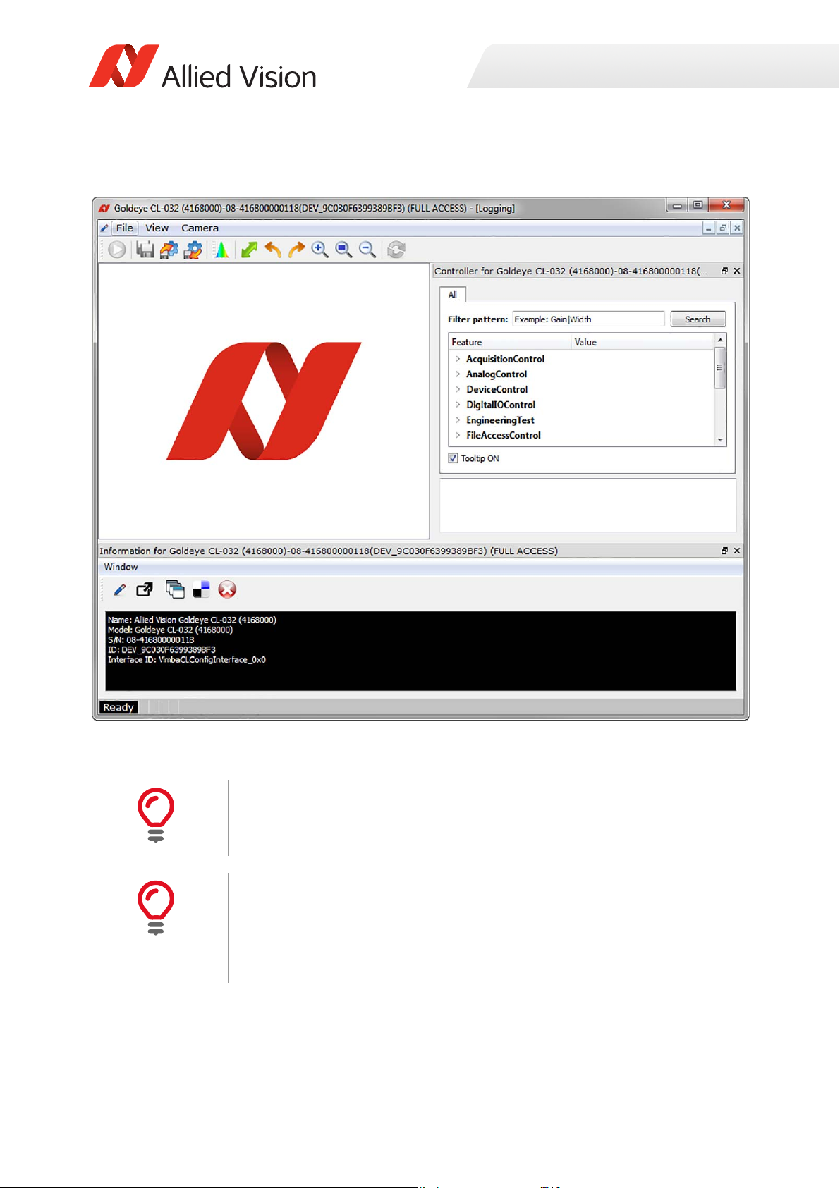
Camera information: Information window
The information window is displayed in the bottom section of the Vimba window,
see Figure 8 on page 42. It consists of the functionalities described below.
To open the Logging window, click the logging icon, shown left. The
logging window provides camera identifying information including the
serial and ID number.
Figure 6: Vimba Viewer with logging window
40Goldeye G/CL Technical Manual V4.1.1

Installation and hardware CL
i
Using a custom application
It is possible to access the Goldeye CL camera without using the Vimba
configuration transport layer. In this case the custom application must open the
COM port of the grabber via the clallserial.dll (or clserXXX.dll) to establish a
communication channel between the host and the camera. The protocol used for
communication with the camera is GenICam GenCP.
Figure 7: Custom GenCP application block diagram
Applicable standards
Two standards are applicable:
• The Camera Link Specification V2.0. You can download it from the AIA website:
http://www.visiononline.org/vision-standards-details.cfm?type=6
• The GenICam GenCP V1.1. You can download it from the EMVA website:
http://www.emva.org/standards-technology/genicam/genicam-downloads/
Using frame grabber transport layer
Some frame grabber manufacturers come with their own Camera Link transport
layer. In this case the Vimba Viewer is not necessary to control the camera.
41Goldeye G/CL Technical Manual V4.1.1

Installation and hardware CL
Adjusting camera features and grabbing images is handled via an application from
the frame grabber manufacturer.
Figure 8: Frame grabber transport layer block diagram
42Goldeye G/CL Technical Manual V4.1.1

Troubleshooting
Helpful hints
Is the camera getting power?
Check the Camera Link status LED underneath the CL port on the backside of the
camera. If the camera is connected to power, the LED should display either or a
continuous green color.
The status LED codes are described in the Goldeye G/CL technical manual. See the
Additional references on page 44.
Installation and hardware CL
Is the camera powered, but not detected in viewer?
• Is the camera connected to the correct grabber port?
If the frame grabber has 2 CL connectors, it should be connected to port 1. If
the grabber has 2 CL connectors, it does not necessarily mean that it is a DUALBASE grabber. Refer to the frame grabber manual for more information.
• Has the camera been powered up and booted completely before the Vimba
Viewer was started?
During the boot process the CL status LED underneath the cameras CL port
flashes with 1 Hz in red/green. After booting has been finished, the LED stays
green.
Note that no Plug-And-Play mechanism is available with Camera Link. If a camera is
attached to the frame grabber after the transport layer is loaded (during start of
Vimba Viewer), the new camera will not be detected. If a camera is removed after
it has been opened it can also not be detected.
Is the camera listed in viewer, but images cannot be acquired?
• Compare the incoming image format of the frame grabber with the parameters
set in the camera. Verify that width, height, and pixel format expected by the
frame grabber are equal at the camera side.
• Check if the frame grabber tap configuration is equal to the camera tap
configuration (Feature
DeviceTapGeometry).
43Goldeye G/CL Technical Manual V4.1.1

Installation and hardware CL
i
Additional references
Product webpage:
https://www.alliedvision.com/en/products/cameras.html
Product manuals:
https://www.alliedvision.com/en/support/technical-documentation.html
Vimba SDK:
https://www.alliedvision.com/en/products/software.html
Knowledge base:
https://www.alliedvision.com/en/support/technical-papers-knowledge-base.html
Software download:
https://www.alliedvision.com/en/support/software-downloads.html
Case studies:
https://www.alliedvision.com/en/applications
Firmware:
To obtain the latest firmware for Allied Vision scientific and IR cameras, please
contact our technical support team:
https://www.alliedvision.com/en/support/contact-support-and-repair.html
44Goldeye G/CL Technical Manual V4.1.1

Specifications
This chapter includes:
• Technical specifications, advanced features, and
measured spectral sensitivity diagrams for each
Goldeye G and CL model
• Frame rates that result when changing the
resolution from smallest to maximum ROI, listing
of frame rates achievable with common video formats, and an explanation of frame rates
calculation
• Technical drawings and dimensions of standard
housing models including available lens mount
adapters
• Information about sensor position accuracy
Goldeye G/CL Technical Manual V4.1.1

Technical overview
Advanced features
• Standard-compliant interfaces:
- Goldeye G cameras with Gigabit Ethernet interface are compliant with GigE
Vision v1.2 standard and support Power over Ethernet (PoE/PoE+, IEEE
802.3af/at)
- Goldeye G cameras have GenICam standard compliant feature control, feature naming in accordance with the SFNC V2.2.0 (Standard Feature Naming
Convention)
- Goldeye CL cameras are compliant to the Camera Link V2.0 standard and
support in addition the GenICam Control Protocoll (GenCP V1.1)
- Goldeye CL cameras have GenICam standard compliant feature control,
feature naming in accordance with the SFNC V2.2.0.
• Support of various innovative InGaAs sensors (FPAs) from a variety of
manufacturers.
• Temperature-stabilized thermo-electric cooling (TEC) and additional heating
available of the FPA to ensure stable and consistently good image quality.
• Temperature monitoring available for both camera and sensor Extended feature set, for example:
- Built-in image correction data sets for non-uniformity correction and
defect pixel correction.
- ROI control including frame rate increase
- Various auto feature control options
- Firmware upload via data-interface
• Support for Allied Vision software solutions: Vimba SDK, AcquireControl (GigE
models only), and others.
• Multi-channel readout to enable maximum sensor frame ratesComprehensive
I/O control options for external triggering, lighting, and device control.
• Compact and lightweight housing.
• Rugged industrial design for machine vision applications (flexible mounting
options, lockable connectors, and others).
Specifications
46Goldeye G/CL Technical Manual V4.1.1

Specifications
Framerates and cooling
Table 4 displays the key sensor features of all Goldeye models. For more detailed
information about temperature control in Goldeye cameras, refer to the section on
Temperature control on page 186.
Models Key features
CL-008 TEC1
G-008 TEC1
InGaAs FPA 320 x 256
344 fps
FPA cooling and heating: TEC1, Min. ΔT = 20K
CL-008 Cool TEC1
G-008 Cool TEC1
CL-032 TEC1
G-032 TEC1
CL-032 Cool TEC2
G-032 Cool TEC2
CL-033 TEC1
G-033 TEC1
CL-033 TECless
G-033 TECless
Table 4: Goldeye key features
InGaAs FPA 320 x 256
344 fps
FPA cooling and heating: TEC1, Min. ΔT = 30K
InGaAs FPA 636 x 508
100 fps
FPA cooling: TEC1, Min. ΔT = 30K
InGaAs FPA 636 x 508
100 fps
FPA cooling: TEC2, Min. ΔT = 60K
InGaAs FPA 640 x 512
301 fps
FPA cooling: TEC1, Min. ΔT= 25K
InGaAs FPA 640 x 512
301 fps
Without thermo-electric cooling (TECless)
Models and modular options
Order code
Model
Goldeye CL-008 TEC1 4168080 4168081 4168083
Goldeye CL-008 Cool TEC1 4168580
Goldeye CL-032 TEC1 4168000 4168001 4168003
Goldeye CL-032 Cool TEC2 4168520
Goldeye CL-033 TEC1 4168030 4168031 4168033
Goldeye CL-033 TECless 4168730
Table 5: Goldeye models and modular options (sheet 1 of 2)
C-Mount
Order code
F-Mount
1 1
1 1
1 1
Order code
M42-Mount
47Goldeye G/CL Technical Manual V4.1.1

Specifications
Order code
Model
Goldeye G-008 TEC1 4068080 4068081 4068083
Goldeye G-008 Cool TEC1 4068580
Goldeye G-032 TEC1 4068000 4068001 4068003
Goldeye G-032 Cool TEC2 4068520 4068521 4068523
Goldeye G-033 TEC1 4068030 4068031 4068033
Goldeye G-033 TECless 4068730
1
Models with F-Mount adapter and M42-Mount adapter are available on
request.
Table 5: Goldeye models and modular options (sheet 2 of 2)
C-Mount
Order code
F-Mount
1 1
1 1
Order code
M42-Mount
Model naming
In addition to family name and model name, the full designation of Goldeye
models can express the temperature control or the housing as well.
Goldeye models are equipped with various active and passive temperature control
devices, for example a Cool housing, or a TEC2, TEC1 or TECless sensor. These
devices are not optional. Also, they are not combinable like a modular design.
When present, each of them constitutes a different Goldeye model. Therefore,
they reflect in the naming or name affix of the model.
Name affix for temperature control
Goldeye models that are equipped with the same sensor may be available with
different temperature controls. To make an unambigous distinction possible, the
temperature control is denoted in the model name.
Name affix Description
TEC2 TEC2 models are equipped with a two-stage thermo-electric
cooling. They are available only with the large Cool housing.
TEC1 TEC1 models are equipped with a single-stage thermo-electric
temperature control. TEC1 models are available with and
without Cool housing.
TECless These models are not equipped with thermo-electric cooling.
Table 6: Distinction between Goldeye models with various TEC stages.
48Goldeye G/CL Technical Manual V4.1.1

Specifications
Note that Table 6 gives only an overview of Goldeye model naming. For more
detailed information on temperature control, refer to Control of the sensor
temperature on page 188.
Example
• Goldeye CL-033 models are available with temperature stabilization and
without temperature control. Names of these models are Goldeye CL-033 TEC1
and Goldeye CL-033 TECless, respectively. Note that it is impossible to distinguish both models without naming the TEC stage.
Name affix for housing size
Goldeye models are available in two different housing sizes. The larger sized
models are denoted with the name affix Cool.
Name affix Cool
(Industrial design) (Scientific design)
Size 78 mm × 55 mm x 55 mm, 90 mm × 80 mm x 80 mm
Nitrogen chamber No Yes
Fan No Yes
Temperature control TEC1 or TECless TEC2 or TEC1
Table 7: Distinctions between Goldeye Cool models and other models
Examples
• Goldeye G-032 models are available with single-stage temperature control,
and with two-stage temperature control in a Cool housing. They are named
Goldeye G-032 TEC1 and Goldeye G-032 Cool TEC2, respectively.
• Goldeye CL-008 models are available with single-stage temperature control in
both housing sizes. They are named Goldeye CL-008 TEC1 and Goldeye CL-008
Cool TEC1, respectively.
49Goldeye G/CL Technical Manual V4.1.1

Technical specifications
Goldeye CL-008 SWIR TEC1
Imaging and performance
Parameter Values
Sensor InGaAs, progressive scan,
Sensor type Focal plane array (FPA)
Specifications
electronic full frame shutter
Spectral range 900 nm to 1700 nm
Resolution 320 (H) × 256 (V)
Pixel size 30 μm × 30 μm
Effective chip size 9.6 mm × 7.68 mm
Dark current
(@ +25 °C FPA temperature)
Temporal dark noise (Gain0) 420 e¯
Temporal dark noise (Gain1) 170 e¯
Saturation capacity (Gain0) 2.5 Me¯
Saturation capacity (Gain1) 170 ke¯
Dynamic range (Gain0) 75 dB
Dynamic range (Gain1) 60 dB
Pixel operability >99.5 %
Maximum frame rate
at full resolution
Exposure time
Temperature control Single-stage thermo-electric cooling and
280 ke¯/s
344 fps
6 µs to 200 ms
heating (TEC1)
1
Analog gain levels Gain0, Gain1
A/D converter 14-bit
Image buffer size 256 MB
Table 8: CL‐008 SWIR TEC1 ‐ Image and performance specifications (sheet 1 of 2)
50Goldeye G/CL Technical Manual V4.1.1

Specifications
Parameter Values
Stream hold capacity 1524 frames at full resolution
1
Maximum exposure value given is valid for Gain0 and sensor temperature of
+25°C. Even longer exposures can be set, but the image quality may
deteriorate.
Table 8: CL‐008 SWIR TEC1 ‐ Image and performance specifications (sheet 2 of 2)
Output
Parameter Values
Digital interface Camera Link Base, up to 2 taps, 40 MHz,
SDR26 connector, Serial Control Channel
Bit depth 8/12/14 bit
Pixel formats Tap geometry 1X 1Y: Mono8, Mono12,
Mono14
Tap geometry 1X2 1Y: Mono8, Mono12
Table 9: CL‐008 SWIR TEC1 ‐ Output specifications
General purpose inputs/outputs
Parameter Values
Opto-isolated I/Os 1 input, 2 outputs
RS232 up to 115 200 Baud, 8N1 (adjustable)
LVTTL I / Os 1 input, 1 output
LVDS Inputs CC1 - CC4
Table 10: CL‐008 SWIR TEC1 ‐ General purpose inputs/output specifications
Mechanics
Parameter Values
Body dimensions (L × W × H)
without lens adapter
Lens mount C-Mount, F-Mount, M42-Mount available
Mass, without adapter 300 g
78 mm × 55 mm x 55 mm
Table 11: CL‐008 SWIR TEC1 ‐ Mechanics specifications(sheet 1 of 2)
51Goldeye G/CL Technical Manual V4.1.1

Parameter Values
Mass, with C-Mount adapter 320 g
Mass, with F-Mount adapter 370 g
Mass, with M42-Mount adapter 340 g
Table 11: CL‐008 SWIR TEC1 ‐ Mechanics specifications(sheet 2 of 2)
Operating conditions
Parameter Values
Operating temperature -20 °C to +55 °C (case)
Storage temperature -30 °C to +70 °C (ambient)
Temperature setpoints +25 °C (default and calibrated)
+20 °C, +35 °C, +50 °C (other setpoints)
or user-confugurable
Relative humidity 10 % to 95 %, non-condensing
Power requirements (DC) 10.8 V to 30.0 V
Specifications
Max. power consumption 10 W (@ 12 VDC)
Typical power consumption
without cooling
2
Even though the first temperature setpoint is pre-configured to +20 °C, it is
possible to set it to a lower temperature. However, if the sensor temperature is
lower than the ambient temperature, especially in humid environments,
condensation may occur.
Table 12: CL‐008 SWIR TEC1 ‐ Operating conditions
4.5 W (@ 12 VDC)
52Goldeye G/CL Technical Manual V4.1.1

Absolute quantum efficiency
SensorFrameRate
10 000 000,,
V2+
H
4
----32+
171+
------------------------------------------------------------------------
=
Specifications
Figure 9: CL‐008 SWIR TEC1 ‐ Absolute quantum efficiency
Resolution and ROI frame rates
The maximum frame rate achievable with Goldeye CL-008 models (in frames per
second — fps) is determined by the ROI size. It can be calculated using the
formulas below.
H ROI: horizontal resolution (width),
the formula is valid if H ≥ 128. For H always use the value rounded up
to the next multiple of 8.
V ROI: vertical resolution (height),
the formula is valid if V ≥ 8. For V always use the value rounded up to
the next multiple of 2.
Formula 1: Calculation of maximum framerate possible with CL‐008 models
53Goldeye G/CL Technical Manual V4.1.1

Specifications
CameraLinkFrameRate
ClFrequency
max 3 H 32+A,
H
Taps
-------------B+
V1–
H
Taps
-------------
CD
++++
----------------------------------------------------------------------------------------------------------------------------------------------------------------------=
FrameRate min SensorFrameRate CameraLinkFrameRate(, )=
When using the formula, please consider the following:
• Round the denominator down to the next full µs.
• Minimum ROI width is 8 pixels, minimum ROI height is 4 pixels.
• The formula generally outputs very exact values, however when the ROI
approaches its minimum size, the exactness decreases by some degree.
• Computational limitations of the host and image capture software may prevent the camera from achieving maximum frame rates.
A
B
C
D
ClMinFValToLValDelay)
ClLValToLValDelay
ClLValToFValDelay
ClMinFValToFValDelay
Formula 1: Calculation of maximum framerate possible with CL‐008 models
Examples for maximum frame rates possible with Goldeye CL-008 models, using a
number of common resolutions, are listed in the table below.
25 MHz 40 MHz
Width Height
Mono 8/12,
2 Taps
Mono 14,
1 Tap
Mono 8/12,
2 Taps
Mono 14,
1 Tap
320 256 344 274 344 344
320 240 366 292 366 366
160 120 1117 1059 1117 1117
128 32 4273 4273 4273 4273
128 8 12345 12345 12345 12345
Table 13: CL‐008 SWIR TEC1 ‐ maximum achievable frame rates
54Goldeye G/CL Technical Manual V4.1.1

Goldeye CL-008 SWIR Cool TEC1
Imaging and performance
Parameter Values
Sensor InGaAs, progressive scan,
electronic full frame shutter
Sensor type Focal plane array (FPA)
Spectral range 900 nm to 1700 nm
Resolution 320 (H) × 256 (V)
Pixel size 30 μm × 30 μm
Effective chip size 9.6 mm × 7.68 mm
Dark current
(@ +5 °C FPA temperature)
Temporal dark noise (Gain0) 420 e¯
160 ke¯/s
Specifications
Temporal dark noise (Gain1) 170 e¯
Saturation capacity (Gain0) 2.5 Me¯
Saturation capacity (Gain1) 170 ke¯
Dynamic range (Gain0) 75 dB
Dynamic range (Gain1) 60 dB
Pixel operability >99.5 %
Maximum frame rate
at full resolution
Exposure time
Temperature control Single-stage thermo-electric cooling and
Analog gain levels Gain0, Gain1
A/D converter 14-bit
Image buffer size 256 MB
Stream hold capacity 1524 frames at full resolution
1
Maximum exposure value given is valid for Gain0 and sensor temperature of
+5°C. Even longer exposures can be set, but the image quality may deteriorate.
Table 14: CL‐008 SWIR Cool TEC1 ‐ Image and performance specifications
344 fps
6 µs to 1250 ms
heating (TEC1)
1
55Goldeye G/CL Technical Manual V4.1.1

Specifications
Output
Parameter Values
Digital interface Camera Link Base, up to 2 taps, 40 MHz,
SDR26 connector, Serial Control Channel
Bit depth 8/12/14 bit
Pixel formats Tap geometry 1X 1Y: Mono8, Mono12,
Mono14
Tap geometry 1X2 1Y: Mono8, Mono12
Table 15: CL‐008 SWIR Cool TEC1 ‐ Output specifications
General purpose inputs/outputs
Parameter Values
Opto-isolated I/Os 1 input, 2 outputs
RS232 up to 115 200 Baud, 8N1 (adjustable)
LVTTL I / Os 1 input, 1 output
LVDS Inputs CC1 - CC4
Table 16: CL‐008 SWIR Cool TEC1 ‐ General purpose inputs/output specifications
Mechanics
Parameter Values
Body dimensions (L × W × H)
without lens adapter
Lens mount C-Mount available,
Mass, without adapter 740 g
Mass, with C-Mount adapter 760 g
Mass, with F-Mount adapter 820 g
90 mm × 80 mm x 80 mm
F-Mount and M42-Mount available on request
Mass, with M42-Mount adapter 780 g
Table 17: CL‐008 SWIR Cool TEC1 ‐ Mechanics specifications
56Goldeye G/CL Technical Manual V4.1.1

Operating conditions
Parameter Values
Operating temperature -20 °C to +55 °C (case)
Storage temperature -30 °C to +70 °C (ambient)
Specifications
Sensor cooling temperature,
setpoints
Relative humidity 10 % to 95 %, non-condensing
Power requirements (DC) 10.8 V to 30.0 V
Max. power consumption 10.5 W (@ 12 VDC)
Typical power consumption
without cooling
Table 18: CL‐008 SWIR Cool TEC1 ‐ Operating conditions
+5 °C (default and calibrated)
-5 °C, +10 °C, +20 °C (other setpoints)
or user-confugurable
5.0 W (@ 12 VDC)
Absolute quantum efficiency
Figure 10: CL‐008 SWIR Cool TEC1 ‐ Absolute quantum efficiency
57Goldeye G/CL Technical Manual V4.1.1

Specifications
SensorFrameRate
10 000 000,,
V2+
H
4
----32+
171+
------------------------------------------------------------------------
=
CameraLinkFrameRate
ClFrequency
max 3
H 32+A,
H
Taps
-------------B+
V1–
H
Taps
-------------
CD
++++
----------------------------------------------------------------------------------------------------------------------------------------------------------------------=
FrameRate min SensorFrameRate CameraLinkFrameRate(, )=
Resolution and ROI frame rates
The maximum frame rate achievable with Goldeye CL-008 models (in frames per
second — fps) is determined by the ROI size. It can be calculated using the
formulas below.
H ROI: horizontal resolution (width),
the formula is valid if H ≥ 128. For H always use the value rounded up
to the next multiple of 8.
V ROI: vertical resolution (height),
the formula is valid if V ≥ 8. For V always use the value rounded up to
the next multiple of 2.
When using the formula, please consider the following:
• Round the denominator down to the next full µs.
• Minimum ROI width is 8 pixels, minimum ROI height is 4 pixels.
• The formula generally outputs very exact values, however when the ROI
approaches its minimum size, the exactness decreases by some degree.
• Computational limitations of the host and image capture software may prevent the camera from achieving maximum frame rates.
A
B
C
D
ClMinFValToLValDelay)
ClLValToLValDelay
ClLValToFValDelay
ClMinFValToFValDelay
Formula 2: Calculation of maximum framerate possible with CL‐008 models
58Goldeye G/CL Technical Manual V4.1.1

Specifications
Examples for maximum frame rates possible with Goldeye CL-008 models, using a
number of common resolutions, are listed in the table below.
25 MHz 40 MHz
Mono 8/12,
Width Height
320 256 344 274 344 344
320 240 366 292 366 366
160 120 1117 1059 1117 1117
128 32 4273 4273 4273 4273
128 8 12345 12345 12345 12345
Table 19: CL‐008 SWIR Cool TEC1 ‐ maximum achievable frame rates
2 Taps
Mono 14,
1 Tap
Mono 8/12,
2 Taps
Mono 14,
1 Tap
59Goldeye G/CL Technical Manual V4.1.1

Goldeye CL-032 SWIR TEC1
Imaging and performance
Parameter Values
Sensor InGaAs, progressive scan,
electronic full frame shutter
Sensor type Focal plane array (FPA)
Spectral range 900 nm to 1700 nm
Resolution 636 (H) × 508 (V)
Pixel size 25 μm × 25 μm
Effective chip size 15.9 mm × 12.7 mm
Dark current
(@ +20 °C FPA temperature)
Temporal dark noise (Gain0) 400 e¯
380 ke¯/s
Specifications
Temporal dark noise (Gain1) 170 e¯
Saturation capacity (Gain0) 1.9 Me¯
Saturation capacity (Gain1) 39 ke¯
Dynamic range (Gain0) 73 dB
Dynamic range (Gain1) 47 dB
Pixel operability >99.5 %
Exposure time
Maximum frame rate
at full resolution
Temperature control Single-stage thermo-electric cooling (TEC1)
Analog gain levels Gain0, Gain1
A/D converter 14-bit
Image buffer size 256 MB
Stream hold capacity 397 frames at full resolution
1
Maximum exposure value given is valid for Gain0 and sensor temperature of
+25°C. Even longer exposures can be set, but the image quality may
deteriorate.
Table 20: CL‐032 SWIR TEC1 ‐ Image and performance specifications
6 µs to 200 ms
100 fps
1
60Goldeye G/CL Technical Manual V4.1.1

Specifications
Output
Parameter Values
Digital interface Camera Link Base, up to 2 taps, 40 MHz,
SDR26 connector, Serial Control Channel
Bit depth 8/12/14 bit
Pixel formats Tap geometry 1X 1Y: Mono8, Mono12,
Mono14
Tap geometry 1X2 1Y: Mono8, Mono12
Table 21: CL‐032 SWIR TEC1 ‐ Output specifications
General purpose inputs/outputs
Parameter Values
Opto-isolated I/Os 1 input, 2 outputs
RS232 up to 115 200 Baud, 8N1 (adjustable)
LVTTL I / Os 1 input, 1 output
LVDS Inputs CC1 - CC4
Table 22: CL‐032 SWIR TEC1 ‐ General purpose inputs/output specifications
Mechanics
Parameter Values
Body dimensions (L × W × H)
without lens adapter
Lens mount C-Mount, F-Mount, M42-Mount available
Mass, body only, without
adapter
Mass, with C-Mount adapter 340 g
Mass, with F-Mount adapter 400 g
78 mm × 55 mm × 55 mm
320 g
Mass, with M42-Mount adapter 360 g
Table 23: CL‐032 SWIR TEC1 ‐ Mechanics specifications
61Goldeye G/CL Technical Manual V4.1.1

Operating conditions
Parameter Values
Operating temperature -20 °C to +55 °C (case)
Storage temperature -30 °C to +70 °C (ambient)
Specifications
Sensor cooling temperature,
setpoints
Relative humidity 10 % to 95 %, non-condensing
Power requirements (DC) 10.8 V to 30.0 V
Max. power consumption 10 W (@ 12 VDC)
Typical power consumption
without cooling
Table 24: CL‐032 SWIR TEC1 ‐ Operating conditions
+20 °C (default and calibrated)
+5 °C, +35 °C, +50 °C (other setpoints)
or user-confugurable
4.5 W (@ 12 VDC)
Absolute quantum efficiency
Figure 11: CL‐032 SWIR TEC1 ‐ Absolute quantum efficiency
62Goldeye G/CL Technical Manual V4.1.1

Specifications
SensorFrameRate
10 000 000,,
V4+
H
4
----32+
131+
------------------------------------------------------------------------
=
CameraLinkFrameRate
ClFrequency
max 3
H 32+A,
H
Taps
-------------B+
V1–
H
Taps
-------------
CD
++++
----------------------------------------------------------------------------------------------------------------------------------------------------------------------=
FrameRate min SensorFrameRate CameraLinkFrameRate(, )=
Resolution and ROI frame rates
The maximum frame rate achievable with Goldeye CL-032 models (in frames per
second — fps) is determined by the ROI size. Calculate the maximum frame rate
using the formula below.
H ROI: horizontal resolution (width).
The formula is valid if H ≥ 128. For H always use the value rounded up
to the next multiple of 16.
V ROI: vertical resolution (height).
The formula is valid if V ≥ 8. For V always use the value rounded up to
the next multiple of 4.
When using the formula, please consider the following:
• Round the denominator down to the next full µs.
• Minimum ROI width is 8 pixels, minimum ROI height is 4 pixels.
• The formula generally outputs very exact values, however when the ROI
approaches its minimum size, the exactness decreases by some degree.
• Computational limitations of the host and image capture software may prevent the camera from achieving maximum frame rates.
A
B
C
D
ClMinFValToLValDelay)
ClLValToLValDelay
ClLValToFValDelay
ClMinFValToFValDelay
Formula 3: Calculation of maximum framerate possible with CL‐032 models
63Goldeye G/CL Technical Manual V4.1.1

Specifications
Examples for maximum frame rates possible with Goldeye CL-032 models, using a
number of common resolutions, are listed in the table below.
Mono 8, Mono 12
(2 Taps)
(ROI (W × H)
636 × 508 (full size) 100 100 73 100
636 × 480 107 107 77 107
320 × 240 351 351 292 351
160 × 120 1047 1047 1047 1047
128 × 32 3507 3507 3507 3507
128 × 8 8264 8264 8264 8264
Table 25: CL‐032 SWIR TEC1 ‐ maximum achievable frame rates
25 MHz 40 MHz 25 MHZ 40 MHz
Mono 14
(1Tap)
64Goldeye G/CL Technical Manual V4.1.1

Goldeye CL-032 SWIR Cool TEC2
Imaging and performance
Parameter Values
Sensor InGaAs, progressive scan,
electronic full frame shutter
Sensor type Focal plane array (FPA)
Spectral range 900 nm to 1700 nm
Resolution 636 (H) × 508 (V)
Pixel size 25 μm × 25 μm
Effective chip size 15.9 mm × 12.7 mm
Dark current
(@ -20 °C FPA temperature)
Temporal dark noise (Gain0) 400 e¯
30 ke¯/s
Specifications
Temporal dark noise (Gain1) 170 e¯
Saturation capacity (Gain0) 1.9 Me¯
Saturation capacity (Gain1) 39 ke¯
Dynamic range (Gain0) 73 dB
Dynamic range (Gain1) 47 dB
Pixel operability >99.5 %
Exposure time
Maximum frame rate
at full resolution
Temperature control Two-stage thermo-electric cooling (TEC2)
Analog gain levels Gain0, Gain1
A/D converter 14-bit
Image buffer size 256 MB
Stream hold capacity 397 frames at full resolution
1
Maximum exposure value given is valid for Gain0 and sensor temperature of
-20°C. Even longer exposures can be set, but the image quality may
deteriorate.
Table 26: CL‐032 SWIR Cool TEC2 ‐ Image and performance specifications
6 µs to 1250 ms
100 fps
1
65Goldeye G/CL Technical Manual V4.1.1

Specifications
Output
Parameter Values
Digital interface Camera Link Base, up to 2 taps, 40 MHz,
SDR26 connector, Serial Control Channel
Bit depth 8/12/14 bit
Pixel formats Tap geometry 1X 1Y: Mono8, Mono12,
Mono14
Tap geometry 1X2 1Y: Mono8, Mono12
Table 27: CL‐032 SWIR Cool TEC2 ‐ Output specifications
General purpose inputs/outputs
Parameter Values
Opto-isolated I/Os 1 input, 2 outputs
RS232 up to 115 200 Baud, 8N1 (adjustable)
LVTTL I / Os 1 input, 1 output
LVDS Inputs CC1 - CC4
Table 28: CL‐032 SWIR Cool TEC2 ‐ General purpose inputs/output specifications
Mechanics
Parameter Values
Body dimensions (L × W × H)
without lens adapter
Lens mount C-Mount available,
Mass, body only, without
adapter
Mass, with C-Mount adapter 780 g
Mass, with F-Mount adapter 840 g
Mass, with M42-Mount adapter 800 g
90 mm × 80 mm × 80 mm
F-Mount and M42-Mount available on request
760 g
Table 29: CL‐032 SWIR Cool TEC2 ‐ Mechanics specifications
66Goldeye G/CL Technical Manual V4.1.1

Operating conditions
Parameter Values
Operating temperature -20 °C to +55 °C (case)
Storage temperature -30 °C to +70 °C (ambient)
Specifications
Sensor cooling temperature,
setpoints
Relative humidity 10 % to 95 %, non-condensing
Power requirements (DC) 10.8 V to 10.8 VDC
Max. power consumption 19 W (@ 12 VDC)
Typical power consumption
without cooling
Table 30: CL‐032 SWIR Cool TEC2 ‐ Operating conditions
-25 °C (default and calibrated)
-5 °C, +10 °C (other setpoints)
or user-confugurable
5.5 W (@ 12 VDC)
Absolute quantum efficiency
Figure 12: CL‐032 SWIR Cool TEC2 ‐ Absolute quantum efficiency
67Goldeye G/CL Technical Manual V4.1.1

Specifications
SensorFrameRate
10 000 000,,
V4+
H
4
----32+
131+
------------------------------------------------------------------------
=
CameraLinkFrameRate
ClFrequency
max 3
H 32+A,
H
Taps
-------------B+
V1–
H
Taps
-------------
CD
++++
----------------------------------------------------------------------------------------------------------------------------------------------------------------------=
FrameRate min SensorFrameRate CameraLinkFrameRate(, )=
Resolution and ROI frame rates
The maximum frame rate achievable with Goldeye CL-032 models (in frames per
second — fps) is determined by the ROI size. Calculate the maximum frame rate
using the formula below.
H ROI: horizontal resolution (width).
The formula is valid if H ≥ 128. For H always use the value rounded up
to the next multiple of 16.
V ROI: vertical resolution (height).
The formula is valid if V ≥ 8. For V always use the value rounded up to
the next multiple of 4.
When using the formula, please consider the following:
• Round the denominator down to the next full µs.
• Minimum ROI width is 8 pixels, minimum ROI height is 4 pixels.
• The formula generally outputs very exact values, however when the ROI
approaches its minimum size, the exactness decreases by some degree.
• Computational limitations of the host and image capture software may prevent the camera from achieving maximum frame rates.
A
B
C
D
ClMinFValToLValDelay)
ClLValToLValDelay
ClLValToFValDelay
ClMinFValToFValDelay
Formula 4: Calculation of maximum framerate possible with CL‐032 models
68Goldeye G/CL Technical Manual V4.1.1

Specifications
Examples for maximum frame rates possible with Goldeye CL-032 models, using a
number of common resolutions, are listed in the table below.
Frame rate max.
Horiz. Res. Vertical Res. Format name
636 508 Sensor full resolution 100
636 480 Approx. matches VGA
format
320 240 Matches QVGA format 351
160 120 Matches 1/4 QVGA format 1047
≤ 128 ≤ 8 (In all resolutions smaller
than this the frame rate
stays the same.)
Table 31: CL‐032: Image resolutions and formats, and resulting maximum frame
rates
[fps]
107
11123
To achieve the highest possible frame rates for different formats, it may become
necessary to change the GigE streaming features, particularly to adjust the GigE
packet size.
• Smaller packets may be advantageous if using small ROIs
• Larger packets may be advantageous if using larger ROIs
69Goldeye G/CL Technical Manual V4.1.1

Specifications
Goldeye CL-033 SWIR TEC1
Imaging and performance
Parameter Values
Sensor InGaAs, progressive scan,
electronic full frame shutter
Sensor type Focal plane array (FPA)
Spectral range 900 nm to 1700 nm
Resolution 640 (H) × 512 (V)
Pixel size 15 μm × 15 μm
Effective chip size 9.6 mm × 7.68 mm
Dark current
Temporal dark noise (Gain0)
Temporal dark noise (Gain2)
Saturation capacity (Gain0)
Saturation capacity (Gain2)
Dynamic range (Gain0)
Dynamic range (Gain2)
110 ke¯/s
390 e¯
32 e¯
1.2 Me¯
25 ke¯
69 dB
59 dB
Pixel operability >99.5 %
Maximum frame rate
301 fps (in 8-bit and 12-bit pixel format)
at full resolution
Exposure time
1 µs to 200 ms
Temperature control Single-stage thermo-electric cooling (TEC1)
Analog gain levels Gain0, Gain1, Gain2
A/D converter 14-bit
Image buffer size 256 MB
Stream hold capacity 392 frames at full resolution
1
Typical values, determined similar to EMVA 1288 under 1200 nm LED
illumination. Given values are mean values of multiple different measurements
at +20 °C FPA temperature, if not stated otherwise.
2
Measured with CDS delay of 12 µs.
3
Maximum exposure value given is valid for Gain0 and sensor temperature of
+25°C. Even longer exposures can be set, but the image quality may
deteriorate.
1
1, 2
1, 2
1, 2
1, 2
1, 2
1, 2
3
Table 32: CL‐033 SWIR TEC1 ‐ Image and performance specifications
70Goldeye G/CL Technical Manual V4.1.1

Specifications
Output
Parameter Values
Digital interface Camera Link Base, up to 2 taps, 85 MHz,
SDR26 connector, Serial Control Channel
Bit depth 8/12/14 bit
Pixel formats Tap geometry 1X 1Y: Mono8, Mono12,
Mono14
Tap geometry 1X2 1Y: Mono8, Mono12
Table 33: CL‐033 SWIR TEC1 ‐ Output specifications
General purpose inputs/outputs
Parameter Values
Opto-isolated I/Os 1 input, 2 outputs
RS232 up to 115 200 Baud, 8N1 (adjustable)
LVTTL I / Os 1 input, 1 output
LVDS Inputs CC1 - CC4
Table 34: CL‐033 SWIR TEC1 ‐ General purpose inputs/output specifications
Mechanics
Parameter Values
Body dimensions (L × W × H)
without lens adapter
Lens mount C-Mount, F-Mount, M42-Mount available
Mass, body only, without
adapter
Mass, with C-Mount adapter 350 g
Mass, with F-Mount adapter 400 g
78 mm × 55 mm × 55 mm
330 g
Mass, with M42-Mount adapter 370 g
Table 35: CL‐033 SWIR TEC1 ‐ Mechanics specifications
71Goldeye G/CL Technical Manual V4.1.1

Operating conditions
Parameter Values
Operating temperature -20 °C to +55 °C (case)
Storage temperature -30 °C to +70 °C (ambient)
Specifications
Sensor cooling temperature,
setpoints
Relative humidity 10 % to 95 %, non-condensing
Power requirements (DC) 10.8 V to 30.0 V
Max. power consumption 11.8 W (@ 12 VDC)
Typical power consumption
without cooling
Table 36: CL‐033 SWIR TEC1 ‐ Operating conditions
+20 °C (default and calibrated)
+5 °C, +35 °C, +50 °C (other setpoints)
or user-confugurable
6.3 W (@ 12 VDC)
Absolute quantum efficiency
Figure 13: CL‐033 SWIR TEC1 ‐ Absolute quantum efficiency
72Goldeye G/CL Technical Manual V4.1.1

Specifications
SensorFrameRate
18 000 000,,
V1+
H
8
----36+
254+
------------------------------------------------------------------------
=
CameraLinkFrameRate
ClFrequency
max 3
H 32+A,
H
Taps
-------------B+
V1–
H
Taps
-------------
CD
++++
----------------------------------------------------------------------------------------------------------------------------------------------------------------------=
FrameRate min SensorFrameRate CameraLinkFrameRate(, )=
Resolution and ROI frame rate
The maximum frame rate achievable with Goldeye CL-033 models (in frames per
second — fps) is determined by the ROI size. Calculate the maximum frame rate
using the formula below.
H ROI: horizontal resolution (width).
The formula is valid if H ≥ 128. For H always use the value rounded up
to the next multiple of 32.
V ROI: vertical resolution (height).
The formula is valid if V ≥ 8. For V always use the value rounded up to
the next multiple of of 4.
When using the formula, please consider the following:
• Round the denominator up or down to the next full µs.
• Minimum ROI width is 8 pixels, minimum ROI height is 4 pixels.
• The formula generally outputs very exact values, however when the ROI
approaches its minimum size, the exactness decreases by some degree.
• Computational limitations of the host and image capture software may prevent the camera from achieving maximum frame rates.
A
B
C
D
ClMinFValToLValDelay)
ClLValToLValDelay
ClLValToFValDelay
ClMinFValToFValDelay
Formula 5: Calculation of maximum framerate possible with CL‐033 models
73Goldeye G/CL Technical Manual V4.1.1

Specifications
Examples for maximum frame rates possible with the Goldeye CL-033, using a
number of common resolutions, are listed in the table below.
Mono 8, Mono 12
(2 Taps)
(ROI (W × H)
640 × 512 (full size) 125 276 301 68 151 234
640 × 480 134 295 321 73 161 250
320 × 256 428 251 909 251 553 855
320 × 240 456 268 968 268 590 912
160 × 120 1404 912 2557 912 2004 2557
128 × 32 5524 3802 9174 3802 8333 9174
128 × 8 17241 12658 25000 12658 25000 25000
Table 37: CL‐033 SWIR TEC1 ‐ maximum achievable frame rates
25 MHz 55 MHz 85 MHz 25 MHz 55 MHz 85 MHz
Mono 14
(1Tap)
74Goldeye G/CL Technical Manual V4.1.1

Specifications
Goldeye CL-033 SWIR TECless
Imaging and performance
Parameter Values
Sensor InGaAs, progressive scan,
electronic full frame shutter
Sensor type Focal plane array (FPA)
Spectral range 900 nm to 1700 nm
Resolution 640 (H) × 512 (V)
Pixel size 15 μm × 15 μm
Effective chip size 9.6 mm × 7.68 mm
Dark current
430 ke¯/s
(@ +45 °C FPA temperature)
Temporal dark noise (Gain0)
Temporal dark noise (Gain2)
Saturation capacity (Gain0)
Saturation capacity (Gain2)
Dynamic range (Gain0)
Dynamic range (Gain2)
390 e¯
32 e¯
1.2 Me¯
25 ke¯
69 dB
59 dB
Pixel operability >99.5 %
Maximum frame rate
301 fps (in 8-bit and 12-bit pixel format)
at full resolution
Exposure time
1 µs to 200 ms
Temperature control Without thermo-electric cooling (TECless)
Analog gain levels Gain0, Gain1, Gain2
A/D converter 14-bit
Image buffer size 256 MB
Stream hold capacity 392 frames at full resolution
1
Typical values, determined similar to EMVA 1288 under 1200 nm LED
illumination. Given values are mean values of multiple different measurements
at +45 °C FPA temperature, if not stated otherwise.
2
Measured with CDS delay of 12 µs.
3
Maximum exposure value given is valid for Gain0 and sensor temperature of
+45°C. Even longer exposures can be set, but the image quality may
deteriorate.
1
1, 2
1, 2
1, 2
1, 2
1, 2
1, 2
3
Table 38: CL‐033 SWIR TECless ‐ Image and performance specifications
75Goldeye G/CL Technical Manual V4.1.1

Specifications
Output
Parameter Values
Digital interface Camera Link Base, up to 2 taps, 85 MHz,
SDR26 connector, Serial Control Channel
Bit depth 8/12/14 bit
Pixel formats Tap geometry 1X 1Y: Mono8, Mono12,
Mono14
Tap geometry 1X2 1Y: Mono8, Mono12
Table 39: CL‐033 SWIR TECless ‐ Output specifications
General purpose inputs/outputs
Parameter Values
Opto-isolated I/Os 1 input, 2 outputs
RS232 up to 115 200 Baud, 8N1 (adjustable)
LVTTL I / Os 1 input, 1 output
LVDS Inputs CC1 - CC4
Table 40: CL‐033 SWIR TECless ‐ General purpose inputs/output specifications
Mechanics
Parameter Values
Body dimensions (L × W × H)
without lens adapter
Lens mount C-Mount available,
Mass, body only, without
adapter
Mass, with C-Mount adapter 320 g
Mass, with F-Mount adapter 370 g
Mass, with M42-Mount adapter 340 g
78 mm × 55 mm × 55 mm
F-Mount and M42-Mount available on request
300 g
Table 41: CL‐033 SWIR TECless ‐ Mechanics specifications
76Goldeye G/CL Technical Manual V4.1.1

Operating conditions
Parameter Values
Operating temperature -20 °C to +55 °C (case)
Storage temperature -30 °C to +70 °C (ambient)
Specifications
Sensor cooling temperature,
setpoints
Relative humidity 10 % to 95 %, non-condensing
Power requirements (DC) 10.8 V to 30.0 V
Max. power consumption 6.0 W (@ 12 VDC)
Typical power consumption 6.0 W (@ 12 VDC)
Table 42: CL‐033 SWIR TECless ‐ Operating conditions
(n/a)
Absolute quantum efficiency
Figure 14: CL‐033 SWIR TECless ‐ Absolute quantum efficiency
77Goldeye G/CL Technical Manual V4.1.1

Specifications
SensorFrameRate
18 000 000,,
V1+
H
8
----36+
254+
------------------------------------------------------------------------
=
CameraLinkFrameRate
ClFrequency
max 3
H 32+A,
H
Taps
-------------B+
V1–
H
Taps
-------------
CD
++++
----------------------------------------------------------------------------------------------------------------------------------------------------------------------=
FrameRate min SensorFrameRate CameraLinkFrameRate(, )=
Resolution and ROI frame rate
The maximum frame rate achievable with Goldeye CL-033 models (in frames per
second — fps) is determined by the ROI size. Calculate the maximum frame rate
using the formula below.
H ROI: horizontal resolution (width).
The formula is valid if H ≥ 128. For H always use the value rounded up
to the next multiple of 32.
V ROI: vertical resolution (height).
The formula is valid if V ≥ 8. For V always use the value rounded up to
the next multiple of of 4.
When using the formula, please consider the following:
• Round the denominator up or down to the next full µs.
• Minimum ROI width is 8 pixels, minimum ROI height is 4 pixels.
• The formula generally outputs very exact values, however when the ROI
approaches its minimum size, the exactness decreases by some degree.
• Computational limitations of the host and image capture software may prevent the camera from achieving maximum frame rates.
A
B
C
D
ClMinFValToLValDelay)
ClLValToLValDelay
ClLValToFValDelay
ClMinFValToFValDelay
Formula 6: Calculation of maximum framerate possible with CL‐033 models
78Goldeye G/CL Technical Manual V4.1.1

Specifications
Examples for maximum frame rates possible with Goldeye CL-033 models, using a
number of common resolutions, are listed in the table below.
Mono 8, Mono 12
(2 Taps)
(ROI (W × H)
640 × 512 (full size) 125 276 301 68 151 234
640 × 480 134 295 321 73 161 250
320 × 256 428 251 909 251 553 855
320 × 240 456 268 968 268 590 912
160 × 120 1404 912 2557 912 2004 2557
128 × 32 5524 3802 9174 3802 8333 9174
128 × 8 17241 12658 25000 12658 25000 25000
Table 43: CL‐033 SWIR TECless ‐ maximum achievable frame rates
25 MHz 55 MHz 85 MHz 25 MHz 55 MHz 85 MHz
Mono 14
(1Tap)
79Goldeye G/CL Technical Manual V4.1.1

Goldeye G-008 SWIR TEC1
Imaging and performance
Parameter Values
Sensor InGaAs, progressive scan,
electronic full frame shutter
Sensor type Focal plane array (FPA)
Spectral range 900 nm to 1700 nm
Resolution 320 (H) × 256 (V)
Pixel size 30 μm × 30 μm
Effective chip size 9.6 mm × 7.68 mm
Dark current
(@ +25 °C FPA temperature)
Temporal dark noise (Gain0) 420 e¯
280 ke¯/s
Specifications
Temporal dark noise (Gain1) 170 e¯
Saturation capacity (Gain0) 2.5 Me¯
Saturation capacity (Gain1) 170 ke¯
Dynamic range (Gain0) 75 dB
Dynamic range (Gain1) 60 dB
Pixel operability >99.5 %
Maximum frame rate
at full resolution
Exposure time
Temperature control Single-stage thermo-electric cooling and
Analog gain levels Gain0, Gain1
A/D converter 14-bit
Image buffer size 256 MB
Stream hold capacity 1524 frames at full resolution
1
Maximum exposure value given is valid for Gain0 and sensor temperature of
+25°C. Even longer exposures can be set, but the image quality may
deteriorate.
344 fps
6 µs to 200 ms
heating (TEC1)
1
Table 44: G‐008 SWIR TEC1 ‐ Image and performance specifications
80Goldeye G/CL Technical Manual V4.1.1

Specifications
Output
Parameter Values
Digital interface GigE Vision
(based on IEEE 802.3 1000BASE-T)
Bit depth 8/12/14 bit
Pixel formats Mono8, Mono12, Mono12Packed, Mono14
Table 45: G‐008 SWIR TEC1 ‐ Output specifications
General purpose inputs/outputs
Parameter Values
Opto-isolated I/Os 1 input, 2 outputs
RS232 up to 115 200 Baud, 8N1 (adjustable)
LVTTL I / Os 1 input, 1 output
Table 46: G‐008 SWIR TEC1 ‐ General purpose inputs/output specifications
Mechanics
Parameter Values
Body dimensions (L × W × H)
without lens adapter
Lens mount C-Mount, F-Mount, M42-Mount available
Mass, body only, without
adapter
Mass, with C-Mount adapter 340 g
Mass, with F-Mount adapter 390 g
Mass, with M42-Mount adapter 360 g
Table 47: G‐008 SWIR TEC1 ‐ Mechanics specifications
78 mm × 55 mm × 55 mm
320 g
81Goldeye G/CL Technical Manual V4.1.1

Operating conditions
Parameter Values
Operating temperature -20 °C to +55 °C (case)
Storage temperature -30 °C to +70 °C (ambient)
Specifications
Sensor cooling temperature,
setpoints **
Relative humidity 10 % to 95 %, non-condensing
Power requirements (DC) 10.8 V to 30.0 V or via PoE
Max. power consumption <12.95 W (@ PoE),
Typical power consumption
without cooling
** Even though the first temperature setpoint is pre-configured to +20 °C, it is
possible to set it to a lower temperature. However, if the sensor temperature is
lower than the ambient temperature, especially in humid environments,
condensation may occur.
Table 48: G‐008 SWIR TEC1 ‐ Operating conditions
+20 °C (default and calibrated)
+25 °C, +35 °C, +50 °C (other setpoints)
or user-confugurable
10.8 W (@ 12 VDC)
6.5 W (@ PoE),
5 W (@ 12 VDC)
Absolute quantum efficiency
Figure 15: G‐008 SWIR TEC1 ‐ Absolute quantum efficiency
82Goldeye G/CL Technical Manual V4.1.1

Specifications
FrameRate
10 000 000,,
V2+
H
4
----32+
171+
------------------------------------------------------------------------
=
Resolution and ROI frame rates
The maximum frame rate achievable with Goldeye G-008 models (in frames per
second — fps) is determined by the ROI size. Calculate the maximum frame rate
using the formula below.
H ROI: horizontal resolution (width).
The formula is valid if H ≥ 128. For H always use the value rounded up
to the next multiple of 8.
V ROI: vertical resolution (height).
The formula is valid if V ≥ 8. For V always use the value rounded up to
the next multiple of 2.
When using the formula, please consider the following:
• Round the denominator down to the next full µs.
• Minimum ROI width is 8 pixels, minimum ROI height is 4 pixels.
• The formula generally outputs very exact values, however when the ROI
approaches its minimum size, the exactness decreases by some degree.
• Computational limitations of the host and image capture software may prevent the camera from achieving maximum frame rates.
Formula 7: Calculation of maximum framerate possible with G‐008 models
Examples for maximum frame rates possible with Goldeye G-008 models, using a
number of common resolutions, are listed in the table below.
Frame rate max.
Horiz. Res. Vertical Res. Format name
320 256 Sensor full resolution 344
320 240 Matches QVGA format 366
160 120 Matches 1/4 QVGA format 1117
128 32 4273
≤ 128 ≤ 8 >=12345
Table 49: G‐008 SWIR TEC1: Image resolutions and formats, and resulting
maximum frame rates
To achieve the highest possible frame rates for different formats, it may become
necessary to change the GigE streaming features, particularly to adjust the GigE
packet size.
• Smaller packets may be advantageous if using small ROIs
• Larger packets may be advantageous if using larger ROIs
[fps]
83Goldeye G/CL Technical Manual V4.1.1

Goldeye G-008 SWIR Cool TEC1
Imaging and performance
Parameter Values
Sensor InGaAs, progressive scan,
electronic full frame shutter
Sensor type Focal plane array (FPA)
Spectral range 900 nm to 1700 nm
Resolution 320 (H) × 256 (V)
Pixel size 30 μm × 30 μm
Effective chip size 9.6 mm × 7.68 mm
Dark current
(@ +5 °C FPA temperature)
Temporal dark noise (Gain0) 420 e¯
160 ke¯/s
Specifications
Temporal dark noise (Gain1) 170 e¯
Saturation capacity (Gain0) 2.5 Me¯
Saturation capacity (Gain1) 170 ke¯
Dynamic range (Gain0) 75 dB
Dynamic range (Gain1) 60 dB
Pixel operability >99.5 %
Maximum frame rate
at full resolution
Exposure time
Temperature control Single-stage thermo-electric cooling and
Analog gain levels Gain0, Gain1
A/D converter 14-bit
Image buffer size 256 MB
Stream hold capacity 1524 frames at full resolution
1
Maximum exposure value given is valid for Gain0 and sensor temperature of
+5°C. Even longer exposures can be set, but the image quality may deteriorate.
Table 50: G‐008 SWIR Cool TEC1 ‐ Image and performance specifications
344 fps
6 µs to 1250 ms
heating (TEC1)
1
84Goldeye G/CL Technical Manual V4.1.1

Specifications
Output
Parameter Values
Digital interface GigE Vision
(based on IEEE 802.3 1000BASE-T)
Bit depth 8/12/14 bit
Pixel formats Mono8, Mono12, Mono12Packed, Mono14
Table 51: G‐008 SWIR Cool TEC1 ‐ Output specifications
General purpose inputs/outputs
Parameter Values
Opto-isolated I/Os 1 input, 2 outputs
RS232 up to 115 200 Baud, 8N1 (adjustable)
LVTTL I / Os 1 input, 1 output
Table 52: G‐008 SWIR Cool TEC1 ‐ General purpose inputs/output specifications
Mechanics
Parameter Values
Body dimensions (L × W × H)
without lens adapter
Lens mount C-Mount available,
Mass, body only, without
adapter
Mass, with C-Mount adapter 790 g
Mass, with F-Mount adapter 840 g
Mass, with M42-Mount adapter 810 g
90 mm × 80 mm x 80 mm
F-Mount and M42-Mount available on request
770 g
Table 53: G‐008 SWIR Cool TEC1 ‐ Mechanics specifications
85Goldeye G/CL Technical Manual V4.1.1

Operating conditions
Parameter Values
Operating temperature -20 °C to +55 °C (case)
Storage temperature -30 °C to +70 °C (ambient)
Specifications
Sensor cooling temperature,
setpoints
Relative humidity 10 % to 95 %, non-condensing
Power requirements (DC) 10.8 V to 30.0 V or via PoE
Max. power consumption <12.95 W (@ PoE),
Typical power consumption
without cooling
Table 54: G‐008 SWIR Cool TEC1 ‐ Operating conditions
+5 °C (default and calibrated)
-5 °C, +10 °C, +20 °C (other setpoints)
or user-confugurable
10.7 W (@ 12 VDC)
6.6 W (@ PoE),
4.9 W (@ 12 VDC)
Absolute quantum efficiency
Figure 16: G‐008 SWIR Cool TEC1 ‐ Absolute quantum efficiency
86Goldeye G/CL Technical Manual V4.1.1

Specifications
FrameRate
10 000 000,,
V2+
H
4
----32+
171+
------------------------------------------------------------------------
=
Resolution and ROI frame rates
The maximum frame rate achievable with Goldeye G-008 models (in frames per
second — fps) is determined by the ROI size. Calculate the maximum frame rate
using the formula below.
H ROI: horizontal resolution (width).
The formula is valid if H ≥ 128. For H always use the value rounded up
to the next multiple of 8.
V ROI: vertical resolution (height).
The formula is valid if V ≥ 8. For V always use the value rounded up to
the next multiple of 2.
When using the formula, please consider the following:
• Round the denominator down to the next full µs.
• Minimum ROI width is 8 pixels, minimum ROI height is 4 pixels.
• The formula generally outputs very exact values, however when the ROI
approaches its minimum size, the exactness decreases by some degree.
• Computational limitations of the host and image capture software may prevent the camera from achieving maximum frame rates.
Formula 8: Calculation of maximum framerate possible with G‐008 models
Examples for maximum frame rates possible with Goldeye G-008 models, using a
number of common resolutions, are listed in the table below.
Frame rate max.
Horiz. Res. Vertical Res. Format name
320 256 Sensor full resolution 344
320 240 Matches QVGA format 366
160 120 Matches 1/4 QVGA format 1117
128 32 4273
≤ 128 ≤ 8 >=12345
[fps]
Table 55: G‐008 SWIR Cool TEC1: Image resolutions and formats, and resulting
maximum frame rates
To achieve the highest possible frame rates for different formats, it may become
necessary to change the GigE streaming features, particularly to adjust the GigE
packet size.
• Smaller packets may be advantageous if using small ROIs
• Larger packets may be advantageous if using larger ROIs
87Goldeye G/CL Technical Manual V4.1.1

Goldeye G-032 SWIR TEC1
Imaging and performance
Parameter Values
Sensor InGaAs, progressive scan,
electronic full frame shutter
Sensor type Focal plane array (FPA)
Spectral range 900 nm to 1700 nm
Resolution 636 (H) × 508 (V)
Pixel size 25 μm × 25 μm
Effective chip size 15.9 mm × 12.7 mm
Dark current
(@ +20 °C FPA temperature)
Temporal dark noise (Gain0) 400 e¯
380 ke¯/s
Specifications
Temporal dark noise (Gain1) 170 e¯
Saturation capacity (Gain0) 1.9 Me¯
Saturation capacity (Gain1) 39 ke¯
Dynamic range (Gain0) 73 dB
Dynamic range (Gain1) 47 dB
Pixel operability >99.5 %
Exposure time
Maximum frame rate
at full resolution
Temperature control Single-stage thermo-electric cooling (TEC1)
Analog gain levels Gain0, Gain1
A/D converter 14-bit
Image buffer size 256 MB
Stream hold capacity 397 frames at full resolution
1
Maximum exposure value given is valid for Gain0 and sensor temperature of
+25°C. Even longer exposures can be set, but the image quality may
deteriorate.
Table 56: G‐032 SWIR TEC1 ‐ Image and performance specifications
6 µs to 200 ms
100 fps
1
88Goldeye G/CL Technical Manual V4.1.1

Specifications
Output
Parameter Values
Digital interface GigE Vision
(based on IEEE 802.3 1000BASE-T)
Bit depth 8/12/14 bit
Pixel formats Mono8, Mono12, Mono12Packed, Mono14
Table 57: G‐032 SWIR TEC1 ‐ Output specifications
General purpose inputs/outputs
Parameter Values
Opto-isolated I/Os 1 input, 2 outputs
RS232 up to 115 200 Baud, 8N1 (adjustable)
LVTTL I / Os 1 input, 1 output
Table 58: G‐032 SWIR TEC1 ‐ General purpose inputs/output specifications
Mechanics
Parameter Values
Body dimensions (L × W × H)
without lens adapter
Lens mount C-Mount, F-Mount, M42-Mount available
Mass, body only, without
adapter
Mass, with C-Mount adapter 370 g
Mass, with F-Mount adapter 420 g
Mass, with M42-Mount adapter 390 g
Table 59: G‐032 SWIR TEC1 ‐ Mechanics specifications
78 mm × 55 mm × 55 mm
350 g
89Goldeye G/CL Technical Manual V4.1.1

Operating conditions
Parameter Values
Operating temperature -20 °C to +55 °C (case)
Storage temperature -30 °C to +70 °C (ambient)
Specifications
Sensor cooling temperature,
setpoints
Relative humidity 10 % to 95 %, non-condensing
Power requirements (DC) 10.8 V to 30.0 V or via PoE
Max. power consumption <12.95 W (@ PoE),
Typical power consumption
without cooling
Table 60: G‐032 SWIR TEC1 ‐ Operating conditions
+20 °C (default and calibrated)
+5 °C, +35 °C, +50 °C (other setpoints)
or user-confugurable
10.8 W (@ 12 VDC)
6.5 W (@ PoE),
5 W (@ 12 VDC)
Absolute quantum efficiency
Figure 17: G‐032 SWIR TEC1 ‐ Absolute quantum efficiency
90Goldeye G/CL Technical Manual V4.1.1

Specifications
FrameRate
10 000 000,,
V 4+
H
4
----32+
131+
-----------------------------------------------------------------------
=
Resolution and ROI frame rates
The maximum frame rate achievable with Goldeye G-032 models (in frames per
second — fps) is determined by the ROI size. Calculate the maximum frame rate
using the formula below.
H ROI: horizontal resolution (width).
The formula is valid if H ≥ 128.
For H always use the value rounded up to the next multiple of 16.
V ROI: vertical resolution (height).
The formula is valid if V ≥ 8.
For V always use the value rounded up to the next multiple of 4.
When using the formula, please consider the following:
• Round the denominator down to the next full µs.
• Minimum ROI width is 8 pixels, minimum ROI height is 4 pixels.
• The formula generally outputs very exact values, however when the ROI
approaches its minimum size, the exactness decreases by some degree.
• Computational limitations of the host and image capture software may prevent the camera from achieving maximum frame rates.
Formula 9: Calculation of maximum framerate possible with G‐032 models
Examples for maximum frame rates possible with Goldeye G-032 models, using a
number of common resolutions, are listed in the table below.
Frame rate max.
Horiz. Res. Vertical Res. Format name
636 508 Sensor full resolution 100
636 480 Approx. matches VGA
format
320 240 Matches QVGA format 351
160 120 Matches 1/4 QVGA format 1047
≤ 128 ≤ 8 (In all resolutions smaller
than this the frame rate
stays the same.)
[fps]
107
11123
Table 61: G‐032 SWIR TEC1: Image resolutions/formats and resulting maximum
frame rates
91Goldeye G/CL Technical Manual V4.1.1

Specifications
To achieve the highest possible frame rates for different formats, it may become
necessary to change the GigE streaming features, particularly to adjust the GigE
packet size.
• Smaller packets may be advantageous if using small ROIs
• Larger packets may be advantageous if using larger ROIs
92Goldeye G/CL Technical Manual V4.1.1

Goldeye G-032 SWIR Cool TEC2
Imaging and performance
Parameter Values
Sensor InGaAs, progressive scan,
electronic full frame shutter
Sensor type Focal plane array (FPA)
Spectral range 900 nm to 1700 nm
Resolution 636 (H) × 508 (V)
Pixel size 25 μm × 25 μm
Effective chip size 15.9 mm × 12.7 mm
Dark current
(@ -20 °C FPA temperature)
Temporal dark noise (Gain0) 400 e¯
30 ke¯/s
Specifications
Temporal dark noise (Gain1) 170 e¯
Saturation capacity (Gain0) 1.9 Me¯
Saturation capacity (Gain1) 39 ke¯
Dynamic range (Gain0) 73 dB
Dynamic range (Gain1) 47 dB
Pixel operability >99.5 %
Exposure time
Maximum frame rate
at full resolution
Temperature control Two-stage thermo-electric cooling (TEC2)
Analog gain levels Gain0, Gain1
A/D converter 14-bit
Image buffer size 256 MB
Stream hold capacity 397 frames at full resolution
1
Maximum exposure value given is valid for Gain0 and sensor temperature of
-20°C. Even longer exposures can be set, but the image quality may
deteriorate.
Table 62: G‐032 SWIR Cool TEC2 ‐ Image and performance specifications
6 µs to 1250 ms
100 fps
1
93Goldeye G/CL Technical Manual V4.1.1

Specifications
Output
Parameter Values
Digital interface GigE Vision
(based on IEEE 802.3 1000BASE-T)
Bit depth 8/12/14 bit
Pixel formats Mono8, Mono12, Mono12Packed, Mono14
Table 63: G‐032 SWIR Cool TEC2 ‐ Output specifications
General purpose inputs/outputs
Parameter Values
Opto-isolated I/Os 1 input, 2 outputs
RS232 up to 115 200 Baud, 8N1 (adjustable)
LVTTL I / Os 1 input, 1 output
Table 64: G‐032 SWIR Cool TEC2 ‐ General purpose inputs/output specifications
Mechanics
Parameter Values
Body dimensions (L × W × H)
without lens adapter
Lens mount C-Mount, F-Mount, M42-Mount available
Mass, body only, without
adapter
Mass, with C-Mount adapter 810 g
Mass, with F-Mount adapter 860 g
Mass, with M42-Mount adapter 830 g
Table 65: G‐032 SWIR Cool TEC2 ‐ Mechanics specifications
90 mm × 80 mm × 80 mm
790 g
94Goldeye G/CL Technical Manual V4.1.1

Operating conditions
Parameter Values
Operating temperature -20 °C to +55 °C (case)
Storage temperature -30 °C to +70 °C (ambient)
Specifications
Sensor cooling temperature,
setpoints
Relative humidity 10 % to 95 %, non-condensing
Power requirements (DC) 10.8 V to 30.0 V or via PoE+
Max. power consumption 22 W (@ PoE+),
Typical power consumption
without cooling
Table 66: G‐032 SWIR Cool TEC2 ‐ Operating conditions
-20 °C (default and calibrated)
-5 °C, +10 °C (other setpoints)
or user-confugurable
19 W (@ 12 VDC)
8 W (@ PoE+),
6 W (@ 12 VDC)
Absolute quantum efficiency
Figure 18: G‐032 SWIR Cool TEC2 ‐ Absolute quantum efficiency
95Goldeye G/CL Technical Manual V4.1.1

Specifications
FrameRate
10 000 000,,
V 4+
H
4
----32+
131+
-----------------------------------------------------------------------
=
Resolution and ROI frame rates
The maximum frame rate achievable with Goldeye G-032 models (in frames per
second — fps) is determined by the ROI size. Calculate the maximum frame rate
using the formula below.
H ROI: horizontal resolution (width).
The formula is valid if H ≥ 128.
For H always use the value rounded up to the next multiple of 16.
V ROI: vertical resolution (height).
The formula is valid if V ≥ 8.
For V always use the value rounded up to the next multiple of 4.
When using the formula, please consider the following:
• Round the denominator down to the next full µs.
• Minimum ROI width is 8 pixels, minimum ROI height is 4 pixels.
• The formula generally outputs very exact values, however when the ROI
approaches its minimum size, the exactness decreases by some degree.
• Computational limitations of the host and image capture software may prevent the camera from achieving maximum frame rates.
Formula 10: Calculation of maximum framerate possible with G‐032 models
Examples for maximum frame rates possible with Goldeye G-032 models, using a
number of common resolutions, are listed in the table below.
Frame rate max.
Horiz. Res. Vertical Res. Format name
636 508 Sensor full resolution 100
636 480 Approx. matches VGA
format
320 240 Matches QVGA format 351
160 120 Matches 1/4 QVGA format 1047
≤ 128 ≤ 8 (In all resolutions smaller
than this the frame rate
stays the same.)
[fps]
107
11123
Table 67: G‐032 SWIR Cool TEC2: Image resolutions and formats, and resulting
maximum frame rates
96Goldeye G/CL Technical Manual V4.1.1

Specifications
To achieve the highest possible frame rates for different formats, it may become
necessary to change the GigE streaming features, particularly to adjust the GigE
packet size.
• Smaller packets may be advantageous if using small ROIs
• Larger packets may be advantageous if using larger ROIs
97Goldeye G/CL Technical Manual V4.1.1

Specifications
Goldeye G-033 SWIR TEC1
Imaging and performance
Parameter Values
Sensor InGaAs, progressive scan,
electronic full frame shutter
Sensor type Focal plane array (FPA)
Spectral range 900 nm to 1700 nm
Resolution 640 (H) × 512 (V)
Pixel size 15 μm × 15 μm
Effective chip size 9.6 mm × 7.68 mm
Dark current
Temporal dark noise (Gain0)
Temporal dark noise (Gain2)
Saturation capacity (Gain0)
Saturation capacity (Gain2)
Dynamic range (Gain0)
Dynamic range (Gain2)
Pixel operability
Maximum frame rate
110 ke¯/s
390 e¯
32 e¯
1.2 Me¯
25 ke¯
69 dB
59 dB
>99.5 %
301 fps (in 8-bit pixel format)
at full resolution
Exposure time
1 µs to 200 ms
Temperature control Single-stage thermo-electric cooling (TEC1)
Analog gain levels Gain0, Gain1, Gain2
A/D converter 14-bit
Image buffer size 256 MB
Stream hold capacity 392 frames at full resolution
1
Typical values, determined similar to EMVA 1288 under 1200 nm LED
illumination. Given values are mean values of multiple different measurements
at 20 °C FPA temperature, if not stated otherwise.
2
Measured with CDS delay of 12 µs.
3
Maximum exposure value given is valid for Gain0 and sensor temperature of
+25°C. Even longer exposures can be set, but the image quality may
deteriorate.
1
1, 2
1, 2
1, 2
1, 2
1, 2
1, 2
1, 2
3
Table 68: G‐033 SWIR TEC1 ‐ Image and performance specifications
98Goldeye G/CL Technical Manual V4.1.1

Specifications
Output
Parameter Values
Digital interface GigE Vision (based on IEEE 802.3 1000BASE-T)
Bit depth 8/12/14 bit
Pixel formats Mono8, Mono12, Mono12Packed, Mono14
Table 69: G‐033 SWIR TEC1 ‐ Output specifications
General purpose inputs/outputs
Parameter Values
Opto-isolated I/Os 1 input, 2 outputs
RS232 up to 115 200 Baud, 8N1 (adjustable)
LVTTL I / Os 1 input, 1 output
Table 70: G‐033 SWIR TEC1 ‐ General purpose inputs/output specifications
Mechanics
Parameter Values
Body dimensions (L × W × H)
without lens adapter
Lens mount C-Mount, F-Mount, M42-Mount available
Mass, body only, without
adapter
Mass, with C-Mount adapter 370 g
Mass, with F-Mount adapter 430 g
Mass, with M42-Mount adapter 390 g
Table 71: G‐033 SWIR TEC1 ‐ Mechanics specifications
78 mm × 55 mm × 55 mm
350 g
99Goldeye G/CL Technical Manual V4.1.1

Operating conditions
Parameter Values
Operating temperature -20 °C to +55 °C (case)
Storage temperature -30 °C to +70 °C (ambient)
Specifications
Sensor cooling temperature,
setpoints
Relative humidity 10 % to 95 %, non-condensing
Power requirements (DC) 10.8 V to 30.0 V or via PoE
Max. power consumption <12.95 W (@ PoE),
Typical power consumption
without cooling
Table 72: G‐033 SWIR TEC1 ‐ Operating conditions
+20 °C (default and calibrated)
+5 °C, +35 °C, +50 °C (other setpoints)
or user-confugurable
10.8 W (@ 12 VDC)
8 W (@ PoE),
6.3W (@ 12 VDC)
Absolute quantum efficiency
Figure 19: G‐033 SWIR TEC1 ‐ Absolute quantum efficiency
100Goldeye G/CL Technical Manual V4.1.1
 Loading...