

Allied Telesis K K TQ1402, TQm1402 Installation Guide
AT-TQ1402 Series
4680
PWR
AT-TQ1402
2.4GHz 5GHz
LAN
Wireless Access Point
AT-TQ1402
AT-TQm1402
Installation Guide
613-002709 Rev. A

Copyright 2019 Allied Telesis, Inc.
All rights reserved. No part of this publication may be reproduced without prior written permission from Allied Telesis, Inc.
Allied Telesis and the Allied Telesis logo are trademarks of Allied Telesis, Incorporated. All other product names, company names,
logos or other designations mentioned herein are trademarks or registered trademarks of their respective owners.
Allied Telesis, Inc. reserves the right to make changes in specifications and other information contained in this document without prior
written notice. The information provided herein is subject to change without notice. In no event shall Allied Telesis, Inc. be liable for
any incidental, special, indirect, or consequential damages whatsoever, including but not limited to lost profits, arising out of or related
to this manual or the information contained herein, even if Allied Telesis, Inc. has been advised of, known, or should have known, the
possibility of such damages.

AT-TQ1402 Series Wireless Access Point Installation Guide
Electrical Safety and Emissions Standards
This product meets the following standards:
“Federal Communications Commission Interference Statement”
“European Union Restriction of the Use of Certain Hazardous Substances (RoHS) in Electrical
and Electronic Equipment” on page 4
“Safety and Electromagnetic Emissions” on page 4
“Translated Safety Statements” on page 7
Federal Communications Commission Interference Statement
Declaration of Conformity
Manufacturer Name: Allied Telesis
Declares that the product: 802.11ac wave2 2x2 2.4G/5G wireless AP
Model Number: AT-TQ1402 and AT-TQm1402
This device complies with Part 15 of the FCC Rules. Operation is subject to the following two
conditions: (1) This device may not cause harmful interference, and (2) this device must accept
any interference received, including interference that may cause undesired operation.
This equipment has been tested and found to comply with the limits for a Class B digital device,
pursuant to Part 15 of the FCC Rules. These limits are designed to provide reasonable protection
against harmful interference in a residential installation. This equipment generates, uses and can
radiate radio frequency energy and, if not installed and used in accordance with the instructions,
may cause harmful interference to radio communications. However, there is no guarantee that
interference will not occur in a particular installation. If this equipment does cause harmful
interference to radio or television reception, which can be determined by turning the equipment
off and on, the user is encouraged to try to correct the interference by one of the following
measures:
• Reorient or relocate the receiving antenna.
• Increase the separation between the equipment and receiver.
• Connect the equipment into an outlet on a circuit different from that to which the receiver is
connected.
• Consult the dealer or an experienced radio/TV technician for help.
3

Caution
FCC Caution: Any changes or modifications not expressly approved by the party responsible
for compliance could void the user's authority to operate this equipment. E80
Avertissement
Avertissement de la FCC: Les changements ou modifications non expressément approuvés
par la partie responsable de la conformité pourraient annuler l'autorité de l'utilisateur à utiliser
cet équipement. E80
This transmitter must not be co-located or operating in conjunction with any other antenna or
transmitter. This device is restricted to indoor use only.
Radiation Exposure Statement:
This equipment complies with FCC radiation exposure limits set forth for an uncontrolled
environment. This equipment should be installed and operated with minimum distance 20 cm
between the radiator and your body.
European Union Restriction of the Use of Certain Hazardous
Substances (RoHS) in Electrical and Electronic Equipment
This Allied Telesis RoHS-compliant product conforms to the European Union Restriction of the
Use of Certain Hazardous Substances (RoHS) in Electrical and Electronic Equipment. Allied
Telesis ensures RoHS conformance by requiring supplier Declarations of Conformity, monitoring
incoming materials, and maintaining manufacturing process controls.
Note
For additional regulatory statements, refer to Appendix B, ”Regulatory Statements” on
page 51.
Safety and Electromagnetic Emissions
Standard Compliance
• RoHs compliant
• European Union RoHS (Directive 2011/65/EU of the European Parliament and of the Council of
8 June 2011 on the restriction of the use of certain hazardous substances in electrical and
electronic equipment.)
4

Wire Communication
• IEEE 802.1
• IEEE 802.3
• IEEE 802.3u
• IEEE 802.3x
• IEEE 802.3af
Wireless Communication
• IEEE 802.11 DSSS
• IEEE 802.11a OFDM
• IEEE 802.11b DSSS/FHSS
• IEEE 802.11g OFDM
• IEEE 802.11n OFDM
• IEEE 802.11ac OFDM
• ARIB STD-T66
AT-TQ1402 Series Wireless Access Point Installation Guide
• ARIB STD-T71
Safety
CB/UL
• UL/IEC 60950-1: 2005+A1:2009+A2:2013 and
EN60950-1:2006+A11:2009+A1:2010+A12:2011+A2:2013
• UL/IEC 62368-1:2014 and EN62368-1:2014
• UL 60950-1, 2nd Edition, 2014-10-14/CSA C22.2 NO. 60950-1-07, 2nd Edition, 2014-10
• IEC 62368-1;2014 AND EN63268-1:2014
• UL 62368-1, 2nd Edition, 2014-12-01
• CSA C22.2 No. 62368-1-14, 2nd Edition, 2014-12-01
TUV
• EN60950-1+EN62368-1 (Co-license)
AEL
• Class I, US FDA/CDRH
• EN(IEC) 60825-1:1994+a11,
• EN(IEC) 60825-2:1994
• EN(IEC) 60950: 1992+A1+A2+A3
5

Electro Magnetic Interference (EMI)
• FCC part15 Subpart B/ Class B
• EN55032 Class B
• CISPR 32
• VCCI Class B
• VCCI-CISPR 32:2016
• AS/NZS CISPR 32
Electro Magnetic Susceptibility (EMS) - EN55024 and EN55035
• IEC 61000-4-2:2008
• IEC 61000-4-3: 2006+A1:2007+A2:2010
• IEC 61000-4-4:2012
• IEC 61000-4-5:2017
• IEC 61000-4-6:2013
• (IEC 61000-4-8:2009)
• IEC 61000-4-11:2014/AMD:2017
• IEC 61000-3-2:2014
• IEC 61000-3-3:2013
FCC
• 47 CFR Part15, subpart C
• 47 CFR Part15, subpart E
CE
• RED Directive 2014/53/EU
• European Council Directive 2014/30/EU
• EN55032:2015+AC:2016
• EN 55024:2010+A1:2015
• EN 301489-1 V2.1.1
• EN 301489-17 V3.1.1
• EN 300328 V2.1.1
• EN 301893 V2.1.1
• EN 62311: 2008/ 50385: 2017
• EN55035:2017
6

AT-TQ1402 Series Wireless Access Point Installation Guide
RCM
• CISPR 32:2015/COR1:2016
• AS/NZS CISPR 32: 2015
• AS/NZS 4268: 2017
Translated Safety Statements
Important: The indicates that a translation of the safety statement is available in a PDF document
titled Translated Safety Statements on the Allied Telesis website at www.alliedtelesis.com/
support.
7

Table of Contents
Preface ............................................................................................................................................................15
Product Description ......................................................................................................................................19
Overview .................................................................................................................................................... 20
Features..................................................................................................................................................... 22
Hardware Features.............................................................................................................................. 22
Management Access ........................................................................................................................... 23
LAN Port .............................................................................................................................................. 23
Redundant Power Supply .......................................................................................................................... 25
LEDs .......................................................................................................................................................... 26
Cable Specifications................................................................................................................................... 27
AT-TQ1402 Series Wireless Access Point Installation ..............................................................................29
Review Safety Precautions ........................................................................................................................ 30
Unpack Shipping Box Contents ................................................................................................................. 32
Installation Guidelines................................................................................................................................ 33
Install Access Point.................................................................................................................................... 34
General Installation Guidelines............................................................................................................ 34
Table Top Installation .......................................................................................................................... 34
Ceiling or Wall - Mounting Bracket Installation .................................................................................... 35
Install Ethernet Cable and External DC Power Supply........................................................................ 40
External AC/DC Power Adapter Installation ........................................................................................ 40
Install Anti-theft Device........................................................................................................................ 41
Ceiling or Wall - Attach Chassis to Mounting Bracket ......................................................................... 42
Start Initial Management Session .............................................................................................................. 44
Technical Specifications ...............................................................................................................................45
Physical Specifications............................................................................................................................... 45
Environmental Specifications..................................................................................................................... 45
Power Specifications.................................................................................................................................. 46
Input Power Specifications .................................................................................................................. 46
External Power Supply Specifications ................................................................................................. 46
PoE Power Requirements ................................................................................................................... 47
Cable Specifications................................................................................................................................... 48
LAN Port Specifications and Pinouts ......................................................................................................... 49
Port Specifications............................................................................................................................... 49
Port Pinouts ......................................................................................................................................... 49
Regulatory Statements .................................................................................................................................51
Federal Communication Commission Interference Statement................................................................... 52
Europe - EU Declaration of Conformity...................................................................................................... 54
Operating Frequencies and Maximum Transmission Power Levels ................................................... 54
Radiation Exposure Statement............................................................................................................ 54
Importer ............................................................................................................................................... 54
9

List of Figures
Figure 1: Top View .......................................................................................................................................... 20
Figure 2: Front Edge View............................................................................................................................... 21
Figure 3: Back Edge View ............................................................................................................................... 21
Figure 4: Acceptable Orientations on a Tabletop, Wall and Ceiling Installation .............................................. 33
Figure 5: Attach Screws to Access Point Chassis........................................................................................... 36
Figure 6: Adjust Screws on Access Point........................................................................................................ 36
Figure 7: Remove Mounting Bracket From Access Point................................................................................ 37
Figure 8: Mark and Pre-Drill Holes for Key-Hole Slots .................................................................................... 38
Figure 9: Mount Bracket On Screws Using Key-Hole Slots............................................................................. 38
Figure 10: Pre-Drill Holes for Mounting Bracket .............................................................................................. 39
Figure 11: Stationary Bracket Position ............................................................................................................ 39
Figure 12: Connect Ethernet Cable to LAN Port ............................................................................................. 40
Figure 13: Connect External AC/DC Power Adapter Cable ............................................................................ 41
Figure 14: Kensington Lock Port Location....................................................................................................... 41
Figure 15: Align/Insert Access Point into Mounting Bracket............................................................................ 42
Figure 16: Seat Access Point onto Mounting Bracket ..................................................................................... 43
Figure 17: Securely Fasten Chassis to Mounting Bracket with Thumbscrew.................................................. 43
Figure 18: Logon Prompt................................................................................................................................. 44
Figure 19: Pin Layout for RJ45 Connector on LAN Port.................................................................................. 49
11

List of Tables
Table 1. Primary Port for Power Source ......................................................................................................... 25
Table 2. LED Status Information .................................................................................................................... 26
Table 3. Shipping Box Components ............................................................................................................... 32
Table 4. Physical Specifications ..................................................................................................................... 45
Table 5. Environmental Specifications ........................................................................................................... 45
Table 6. Input Power Specifications ............................................................................................................... 46
Table 7. External Power Supply Specifications .............................................................................................. 46
Table 8. PoE Power Requirements ................................................................................................................ 47
Table 9. LAN Port Twisted Pair Cable Requirements .................................................................................... 48
Table 10. LAN Port Specifications .................................................................................................................. 49
Table 11. MDI Pin Signals (10Base-T or 100Base-TX) .................................................................................. 49
Table 12. MDI-X Pin Signals (10Base-T or 100Base-TX) .............................................................................. 50
Table 13. Connector Pinouts (1000Base-T) ................................................................................................... 50
13

Preface
This guide contains the hardware installation instructions for the
AT-TQ1402 Series Wireless Access Point. This preface contains the
following sections:
“Safety Symbols Used in this Document” on page 16
“Contacting Allied Telesis” on page 17
15
Preface
Safety Symbols Used in this Document
This document uses the following conventions.
Note
Notes provide additional information.
Caution
Cautions inform you that performing or omitting a specific action
may result in equipment damage or loss of data.
Warning
Warnings inform you that performing or omitting a specific action
may result in bodily injury.
16

Contacting Allied Telesis
If you need assistance with this product, you may contact Allied Telesis
technical support by going to the Support & Services section of the Allied
Telesis web site at www.alliedtelesis.com/support. You can find links for
the following services on this page:
24/7 Online Support — Enter our interactive support center to
search for answers to your product questions in our knowledge
database, check support tickets, learn about Return Merchandise
Authorizations (RMAs), and contact Allied Telesis technical
experts.
USA and EMEA phone support — Select the phone number that
best fits your location and customer type.
Hardware warranty information — Learn about Allied Telesis
warranties and register your product online.
Replacement Services — Submit an RMA request via our
interactive support center.
AT-TQ1402 Series Wireless Access Point Installation Guide
Documentation — View the most recent installation and user
guides, software release notes, white papers, and data sheets for
your products.
Software Downloads — Download the latest software releases for
your managed products.
For sales or corporate information, go to www.alliedtelesis.com/
purchase.
17

Chapter 1
Product Description
This chapter describes the hardware components of the AT-TQ1402
Series Wireless Access Point. This chapter contains the following
sections:
“Overview” on page 20
“Features” on page 22
“LAN Port” on page 23
“Redundant Power Supply” on page 25
“LEDs” on page 26
“Cable Specifications” on page 27
19
Chapter 1: Product Description
4681
5GHz
2.4GHz
PWR
LAN
AT-TQ1402
Overview
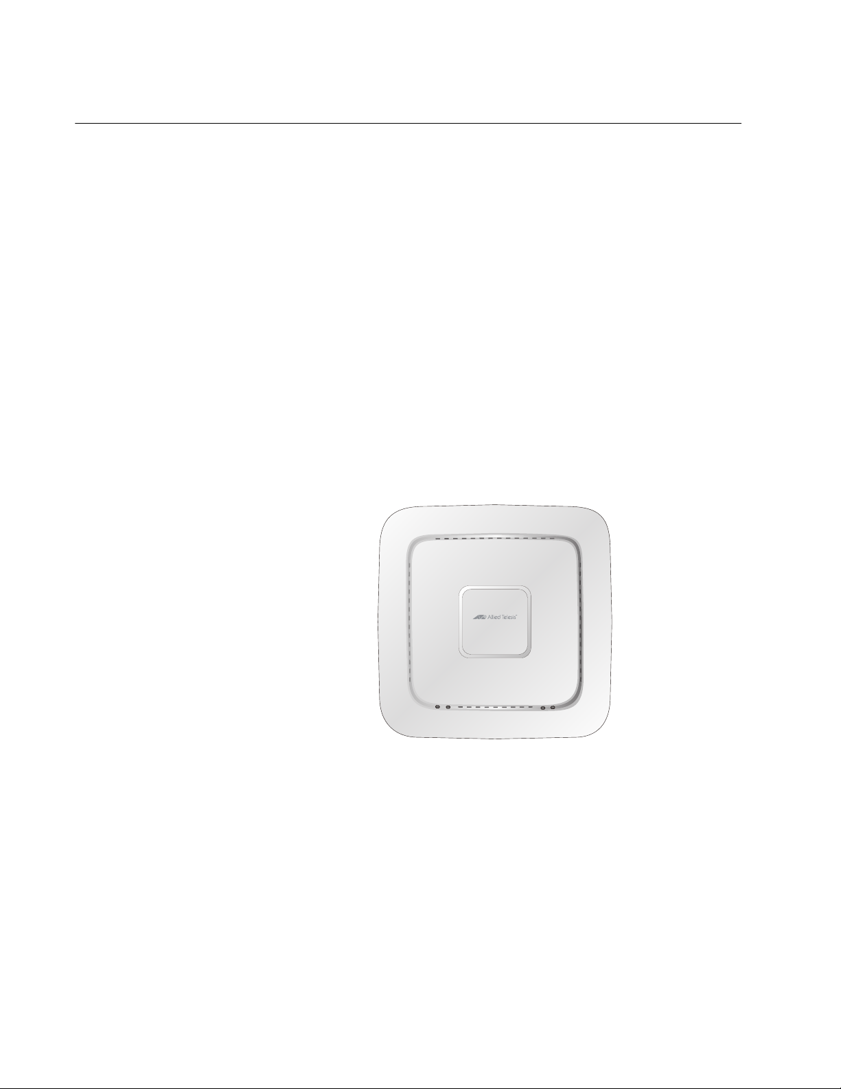
The AT-TQ1402 Series Access Point is a dual-band access point
designed to connect wireless devices to your local area network. This
device can be mounted on a ceiling, wall or tabletop.
It is equipped with:
PoE-capable Ethernet port
DC-IN jack for an external power supply with a DC power switch
Console port for manufacturing purposes only
Power On/Off button
Reset button
Kensington lock port for physical security in your installation
environment.
The top view of the AT-TQ1402 Series is illustrated in Figure 1.
Back Edge
Front Edge
Figure 1. Top View
20
 Loading...