

Page 1

CONVERTEON™ Family
Media Converter Chassis
AT-CV5001
Installation Guide
613-001246 Rev. A
Page 2

Copyright 2009 Allied Telesis, Inc.
All rights reserved. No part of this publication may be reproduced without prior written permission from Allied Telesis, Inc.
Allied Telesis, the Allied Telesis logo, and Converteon are trademarks of Allied Telesis, Incorporated. All other product names, company
names, logos or other designations mentioned herein are trademarks or registered trademarks of their respective owners.
Allied Telesis, Inc. reserves the right to make changes in specifications and other information contained in this document without prior
written notice. The information provided herein is subject to change without notice. In no event shall Allied Telesis, Inc. be liable for any
incidental, special, indirect, or consequential damages whatsoever, including but not limited to lost profits, arising out of or related to this
manual or the information contained herein, even if Allied Telesis, Inc. has been advised of, known, or should have known, the possibility of
such damages.
Page 3
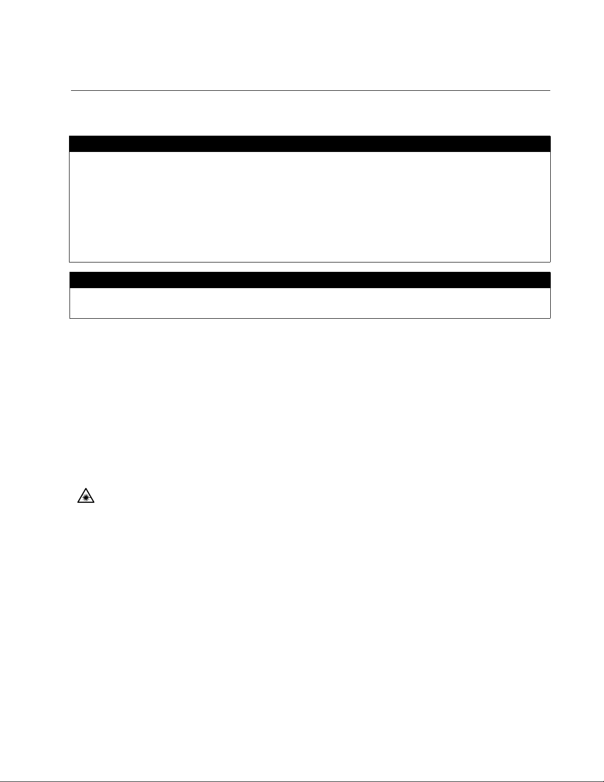
Electrical Safety and Emissions Standards
This product meets the following standards.
U.S. Federal Communications Commission
Radiated Energy
Note: This equipment has been tested and found to comply with the limits for a Class A digital device pursuant to Part 15
of FCC Rules. These limits are designed to provide reasonable protection against harmful interference when the
equipment is operated in a commercial environment. This equipment generates, uses , and can radiate radio frequency
energy and, if not installed and used in accordance with this instruction manual, may cause harmful interference to radio
communications. Operation of this equipment in a residential area is likely to cause harmful interference in which case
the user will be required to correct the interference at his own expense.
Note: Modifications or changes not expressly approved of by the manufacturer or the FCC, can void your right to operate
this equipment.
Industry Canada
This Class B digital apparatus complies with Canadian ICES-003.
Cet appareil numérique de la classe A est conforme à la norme NMB-003 du Canada.
RFI Emissions FCC Class A, EN55022 Class A, EN61000-3-2, EN61000-3-3, VCCI
Class A, C-TICK, CE
Warning: In a domestic environment this product may cause radio interference in
which case the user may be required to take adequate measures.
Immunity EN55024
Electrical Safety EN60950 (TUV), UL 60950 (
CULUS
)
Laser Safety EN60825
3
Page 4

Translated Safety Statements
Important: The indicates that a translation of the safety statement is available in a PDF
document titled “Translated Safety Statements” (613-000990) posted on the Allied Telesis website at
www.alliedtelesis.com.
4
Page 5

Contents
Preface ...............................................................................................................................................................................11
Safety Symbols Used in this Document...............................................................................................................................12
Where to Find Web-based Guides ............................................................ ..........................................................................13
Contacting Allied Telesis .....................................................................................................................................................14
Online Support .............................................................................................................................................................14
Email and Telephone Support......................................................................................................................................14
Returning Products.......................................................................................................................................................14
Sales or Corporate Information....................................................................................................................................14
Warranty.......................................................................................................................................................................14
Management Software Updates................................................................................................................................... 14
Chapter 1: Overview .........................................................................................................................................................15
AT-CV5001 Chassis Overview............................................................................................................................................16
Front and Rear Panel Components.....................................................................................................................................17
Media Converter Cards........................................................................................................................................................18
AT-CV5M02 Management Card..........................................................................................................................................19
AT-CV5001AC and AT-CV5001DC Power Supply Modules...............................................................................................21
Automatic Fan Speed Control......................................................................................................................................21
Power Supply Alerts and Shutdown.............................................................................................................................22
AT-CV5000 Chassis............................................................................................................................................................ 23
AT-CV5LED Card................................................................ .................................... ............................................................ 24
Chapter 2: Installation ......................................................................................................................................................27
Reviewing the Safety Precautions.......................................................................................................................................28
Selecting a Site for the Chassis...........................................................................................................................................31
Unpacking the Chassis..........................................................................................................
Installing the AT-CV5001 Chassis in a Rack.......................................................................................................................34
Grounding the AT-CV5001 Chassis ....................................................................................................................................36
Installing the AT-CV5001AC Power Supply.........................................................................................................................38
Installing the AT-CV5001DC Power Supply ........................................................................................................................43
Installing the Media Converter Line Cards...........................................................................................................................47
Installing the AT-CV5M02 Management Card.....................................................................................................................52
Powering On an AC Powered Chassis................................................................................................................................57
Powering On a DC Powered Chassis..................................................................................................................................59
Chapter 3: Removing or Replacing Line Cards or Power Supply Modules ................................................................63
Removing or Replacing Media Converter Line Cards .........................................................................................................64
Removing or Replacing the AT-CV5001AC Power Supply .................................................................................................69
Removing or Replacing the AT-CV5001DC Power Supply.................................................................................................73
Chapter 4: Troubleshooting .............................................................................................................................................77
Appendix A: Technical Specifications ............................................................................................................................79
Physical Specifications........................................................................................................................................................79
Environmental Specifications...............................................................................................................................................79
Power Specifications...........................................................................................................................................................79
AT-CV5001AC Power Supply Module..........................................................................................................................79
AT-CV5001DC Power Supply Module.................................. ........................................................................................80
Power Supply Module Fuse Specifications..........................................................................................................................80
Safety and Electromagnetic Emissions Certifications..........................................................................................................80
..............................................32
5
Page 6

Contents
Appendix B: Cleaning Fiber Optic Connectors ..............................................................................................................81
Using a Cartridge-Type Cleaner...................................... .. ..................................... ... .. ........................................................82
Using a Swab..................................................... .............................................................. ....................................................84
6
Page 7

Figures
Figure 1. AT-CV5001 Chassis........................................................................................................................................... 16
Figure 2. Front Panel......................................................................................................................................................... 17
Figure 3. Rear Panel ......................................................................................................................................................... 17
Figure 4. AT-CV5M02 Management Card......................................................................................................................... 19
Figure 5. AT-CV5LED Card............................................................................................................................................... 24
Figure 6. Removing the Feet............................................................................................................................................. 34
Figure 7. Removing the Feet............................................................................................................................................. 34
Figure 8. Installing the Brackets........................................................................................................................................ 35
Figure 9. Mounting the AT-CV5001 Chassis in a 19-inch Equipment Rack...................................................................... 35
Figure 10. Connecting the Wire to the Ground Lug........................................................................................................... 36
Figure 11. Removing the Grounding Lug Screws.............................................................................................................. 36
Figure 12. Attaching the Grounding Lug to the Chassis.................................................................................................... 37
Figure 13. Removing the Cover from Slot B...................................................................................................................... 40
Figure 14. Inserting the AT-CV5001AC Power Supply...................................................................................................... 41
Figure 15. Securing the AT-CV5001AC Power Supply ..................................................................................................... 42
Figure 16. Removing the Cover from Slot B...................................................................................................................... 44
Figure 17. Inserting the AT-CV5001DC Power Supply...................................................................................................... 45
Figure 18. Securing the AT-CV5001DC Power Supply..................................................................................................... 46
Figure 19. Removing a Blank Slot Cover........................................................................................................................... 48
Figure 20. Alignment Guides............................................................................................................................................. 49
Figure 21. Inserting a Line Card........................................................................................................................................ 50
Figure 22. Tightening the Captive Screw........................................................................................................................... 50
Figure 23. Removing a Slot Cover..................................................................................................................................... 53
Figure 24. Installing the AT-CV5M02 Management Card.................................................................................................. 55
Figure 25. Tightening the Captive Screw........................................................................................................................... 56
Figure 26. Connecting the AC Power Cord ....................................................................................................................... 57
Figure 27. DC Terminal Block on the AT-CV5001DC Power Supply Module...........................................................
Figure 28. Stripped Wire.................................................................................................................................................... 60
Figure 29. Inserting Wires into a DC Terminal Block......................................................................................................... 60
Figure 30. Labeling and Removing the Network Cables ................................................................................................... 64
Figure 31. Installing the Dust Cap..................................................................................................................................... 65
Figure 32. Removing the SFP Module............................................................................................................................... 65
Figure 33. Loosening the Captive Screw........................................................................................................................... 66
Figure 34. Removing a Line Card...................................................................................................................................... 67
Figure 35. Removing the Power Cord from the AT-CV5001AC Power Supply................................................................. 69
Figure 36. Loosening the Captive Screws on the AT-CV5001AC Power Supply.............................................................. 70
Figure 37. Removing the AT-CV5001AC Power Supply ................................................................................................... 71
Figure 38. Installing the Slot Cover.................................................................................................................................... 72
Figure 39. Loosening the Captive Screws on the AT-CV5001AC Power Supply.............................................................. 74
Figure 40. Removing the AT-CV5001AC Power Supply ................................................................................................... 75
Figure 41. Installing the Slot Cover.................................................................................................................................... 76
Figure 42. Ferrule in an SC Connector Plug...................................................................................................................... 81
Figure 43. Unclean and Clean Ferrule............................................................................................................................... 81
Figure 44. Cartridge Cleaner............................................................................................................................................. 82
Figure 45. Rubbing the Ferrule Tip on the Cleaning Surface ............................................................................................ 83
Figure 46. Lint-Free and Alcohol-Free Swabs................................................................................................................... 84
Figure 47. Cleaning a Recessed Ferrule................................................................................. ... ... .................................... 84
......... 59
7
Page 8

Figures
8
Page 9

Tables
Table 1. Safety Symbols ....................................................................................................................................................12
Table 2. Status LEDs on the AT-CV5LED Card ................................................................................................................24
Table 3. AT-CV5001 Chassis Components .......................................................................................................................32
Table 4. AT-CV5001AC Power Supply Components ........................................................................................................38
Table 5. AT-CV5001DC Power Supply Component ..........................................................................................................43
Table 6. AT-CV5M02 Management Card Components .....................................................................................................54
Table 7. Power Supply Fuse Specifications ......................................................................................................................80
9
Page 10

Tables
10
Page 11

Preface
This guide contains the installation instructions for the Converteon™
AT-CV5001 Chassis. This preface contains the following sections:
“Safety Symbols Used in this Document” on page 12
“Where to Find Web-based Guides” on page 13
“Contacting Allied Telesis” on page 14
11
Page 12
Preface
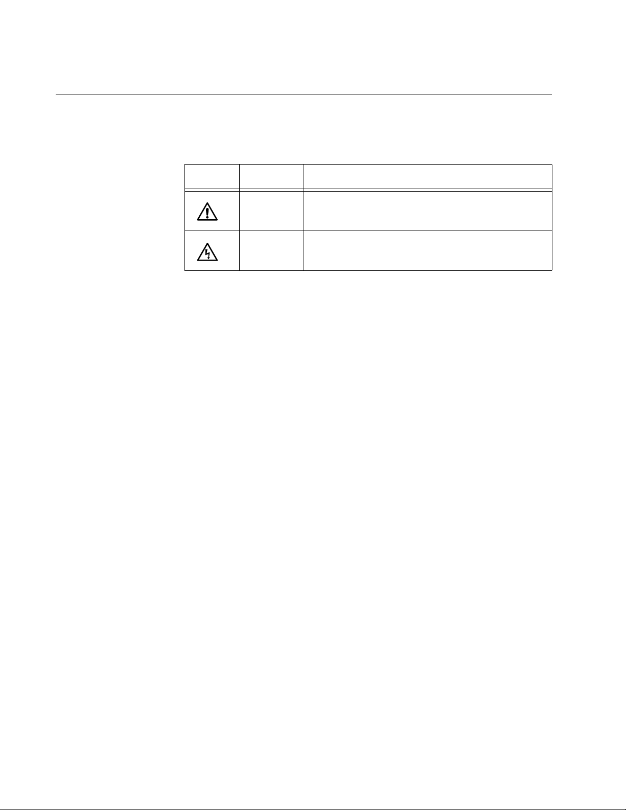
Safety Symbols Used in this Document
This document uses the safety symbols defined in Table 1.
Table 1. Safety Symbols
Symbol Meaning Description
Caution Performing or omitting a specific action may
result in equipment damage or loss of data.
Warning Performing or omitting a specific action may
result in electrical shock.
12
Page 13

Where to Find Web-based Guides
The installation and user guides for all Allied Telesis products are available
in portable document format (PDF) from our web site at
www.alliedtelesis.com. You can view the documents online or download
them onto a local workstation or server.
AT-CV5001 Media Converter Chassis Installation Guide
13
Page 14

Preface
Contacting Allied Telesis
This section provides Allied Telesis contact information for technical
support and for sales and corporate information.
This section provides Allied Telesis contact information for technical
support and for sales and corporate information.
Online Support You can request technical support online by accessing the Allied Telesis
Knowledge Base: www.alliedtelesis.com/support/kb.aspx. You can use
the Knowledge Base to submit questions to our technical support staff and
review answers to previously asked questions.
Email and
Telephone
Support
Returning
Products
Sales or
Corporate
Information
Warranty For hardware warranty information, refer to the Allied Telesis web site at
Management
Software Updates
For Technical Support via email or telephone, refer to the Allied Telesis
web site at www.alliedtelesis.com. Select your country from the list on
the web site and then select the appropriate tab.
Products for return or repair must first be assigned a return materials
authorization (RMA) number. A product sent to Allied Telesis without an
RMA number will be returned to the sender at the sender’s expense. For
instructions on how to obtain an RMA number, go to the Support section
on our web site at www.alliedtelesis.com.
You can contact Allied Telesis for sales or corporate information through
our web site at www.alliedtelesis.com.
www.alliedtelesis.com/support/warranty.
New releases of the management software for our managed products are
available from the following Internet sites:
Allied Telesis web site: www.alliedtelesis.com
14
Allied Telesis FTP server: ftp://ftp.alliedtelesis.com
If the FTP server prompts you to log on, enter “anonymous” as the user
name and your email address as the password.
Page 15

Chapter 1
Overview
This chapter contains the following sections:
“AT-CV5001 Chassis Overview” on page 16
“Front and Rear Panel Components” on page 17
“Media Converter Cards” on page 18
“AT-CV5M02 Management Card” on page 19
“AT-CV5001AC and AT-CV5001DC Power Supply Modules” on
page 21
“AT-CV5000 Chassis” on page 23
“AT-CV5LED Card” on page 24
15
Page 16
Chapter 1: Overview
Note
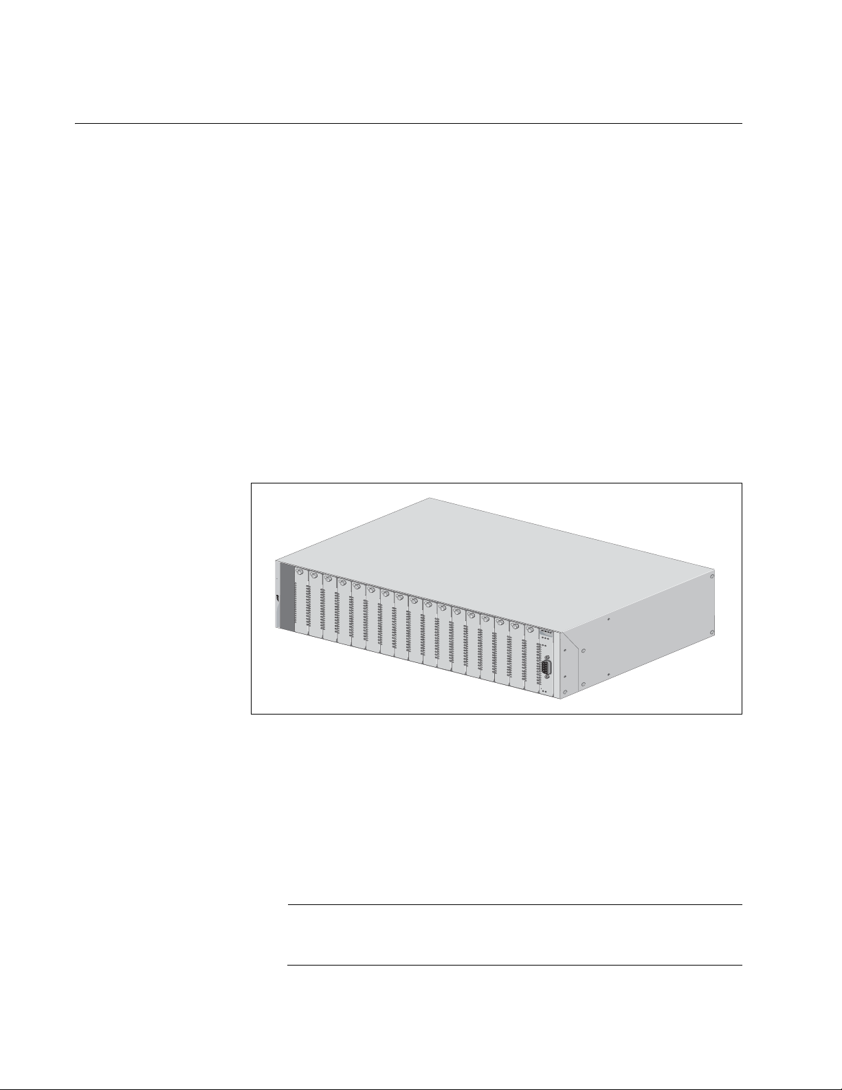
AT-CV5001 Chassis Overview
The AT-CV5001 Chassis is a member of the Converteon family of media
converter products. The product is used to aggregate large numbers of
geographically separate Fast Ethernet or Gigabit Ethernet networks into a
central location, over fiber optic cables. The features of the chassis are:
Eighteen slots for media converter line cards and the AT-CV5M02
Management Card
Two slots for primary and redundant AC or DC power supplies
Support for all AT-CV, AT-CM2, and AT-CM3 Series Media Converter
Cards, as well as the double-slot AT-CM70S Media Converter Card
Support for the AT-CV5M02 Management Card
Variable fan speed control
Rack-mount or tabletop installation
Operations, Administration, and Maintenance (OAM) with the
AT-CV5M02 Management Card
AT-CV5001
Allied Telesis
R
DY MSTR FLT
F
AN
1
PS1
P
S
A
P
S
B
R
D
Y
R
E
S
E
T
L
IN
E
/S
F
M
FA
N
A
FA
N
B
1648
Figure 1. AT-CV5001 Chassis
The chassis supports all the same features as the AT-CV5000 Chassis,
including Operations, Administration, and Maintenance (OAM). This
feature lets you perform loopback tests between the media converter
cards and remote devices, receive notification of power supply problems
at remote sites with the dying gasp and the first RPS failure signals, and
more. For descriptions of the OAM features, refer to the AT-S73, AT-S99,
and AT-S102 Management Software User’s Guide.
The chassis does not come with a power supply, Power supplies
must be ordered separately.
16
Page 17
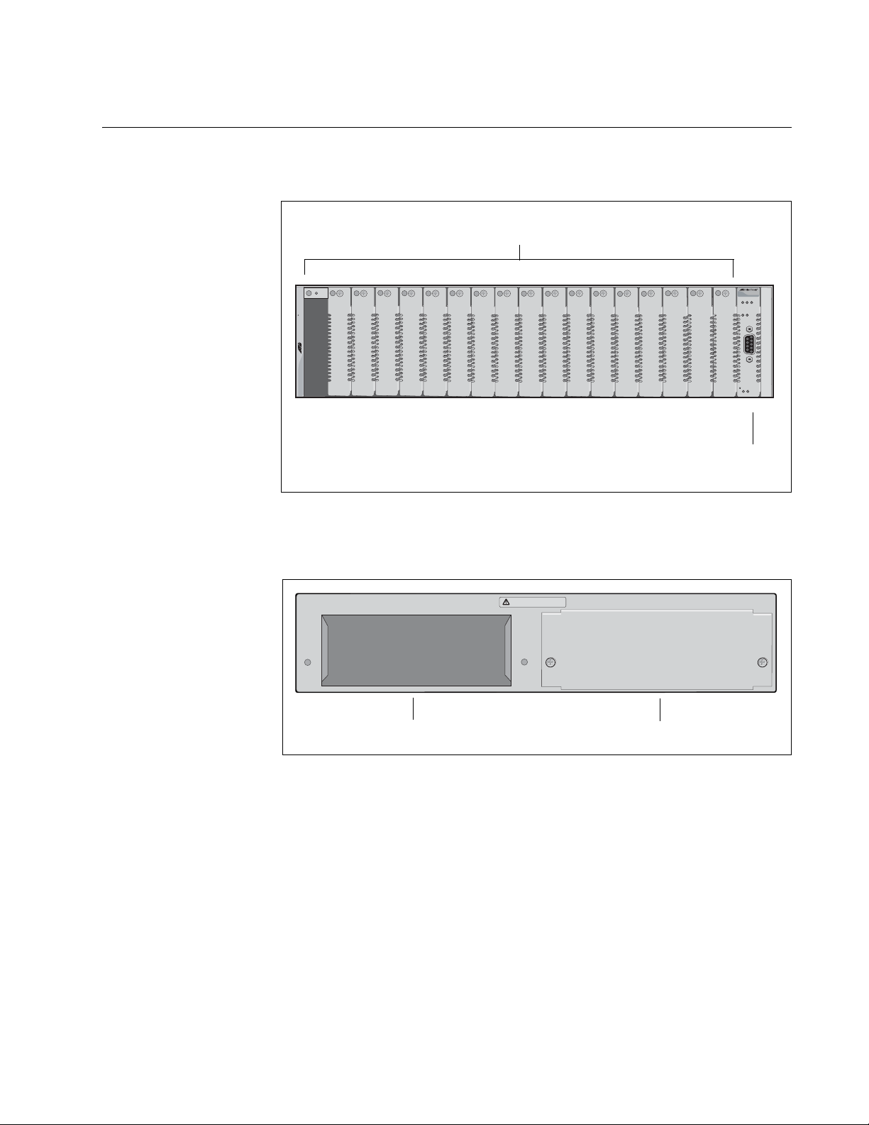
Front and Rear Panel Components
Line Card Slots
LED Interface
Card
Power Supply Slot A
Power Supply Slot B
Figure 2 shows the front panel of the AT-CV5001 Chassis.
AT-CV5001 Media Converter Chassis Installation Guide
4
3
5
7
6
9
8
10
12
11
13
AT-CV5001
Allied Telesis
1
2
Figure 2. Front Panel
Figure 3 illustrates the rear panel of the chassis.
WARNING
This unit might have more than one power input. To reduce the risk
AB
of electric shock, disconnect all power inputs before servicing unit.o
16
15
14
18
17
RD
Y FL
T MASTER
F
AN
1
PS1
P
S
-A
P
S-
R
D
Y
RESET LINE/EXP
FAN-A FAN-B
B
1649
1662
Figure 3. Rear Panel
17
Page 18

Chapter 1: Overview
Media Converter Cards
The chassis supports all the Converteon media converter cards, which
include the following:
AT-CV Series
AT-CM2 Series
AT-CM3 Series
AT-CM70S Card
The cards can be installed in the chassis in any combination and in any
order. For descriptions of the cards, refer to their datasheets on the Allied
Telesis web site, their Installation Guides, which are also available on the
Allied Telesis web site, or the AT-S73, AT-S99, and AT-S102
Management Software User’s Guide.
18
Page 19
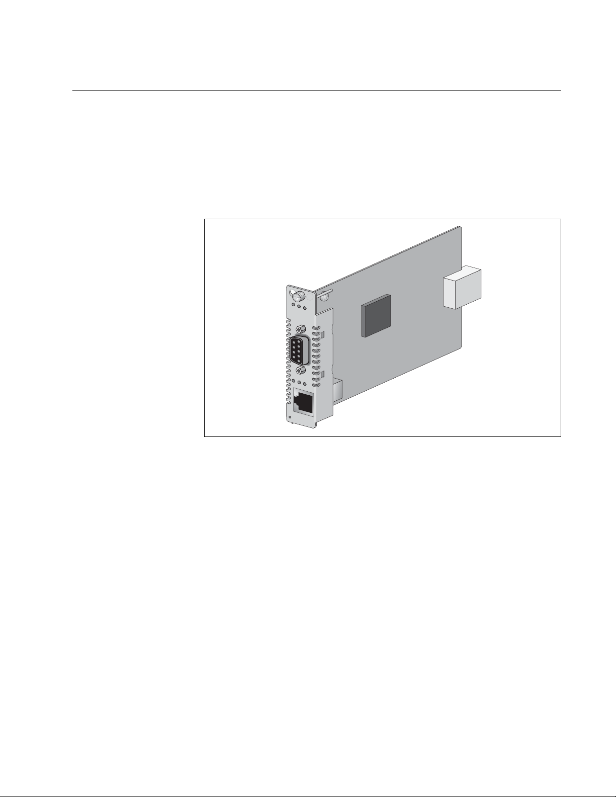
AT-CV5M02 Management Card
The chassis and the media converter cards are operational as soon as
they are installed and powered on, and can be used as unmanaged
devices.
If management is desired, you can install the AT-CV5M02 Management
Card. This card lets you monitor the operational states of the cards and the
chassis, and configure their parameters.
AT-CV5M02
PW
R RDY FL
AT-CV5001 Media Converter Chassis Installation Guide
T
L
K
AT
F
D
CPU RESET
240
Figure 4. AT-CV5M02 Management Card
Here are the features of the AT-CV5M02 Management Card:
Local (out-of-band) management through the RS-232 Console port.
Remote (in-band) management using the card’s Telnet server from
Telnet clients on your network.
Remote (in-band) management using a web browser.
Remote (in-band) management using SNMPv1, SNMPv2c, or
SNMPv3.
Easy-to-use menus and web browser windows.
Event log for viewing operational messages about the line cards.
Activity monitor for viewing the event messages in real-time.
Syslog client for storing the event messages on a syslog server on
your network.
Network Time Protocol (NTP) client for setting the card’ s date and time
from an NTP server on your network or the Internet.
19
Page 20

Chapter 1: Overview
Note
Dynamic Host Control Protocol (DHCP) client for assigning the
management card’s IP address configuration from a BOOTP or DHCP
server on your network.
Redundant management cards in the AT-CV5001 Chassis.
Manual or automatic restoration of previous configurations to the local
or remote AT-CM Line Cards.
For descriptions of the management features, refer to the
Converteon AT-S73, AT-S99 and AT-S102 Management Software
User’s Guide, available from the Allied Telesis web site.
20
Page 21

AT-CV5001 Media Converter Chassis Installation Guide
AT-CV5001AC and AT-CV5001DC Power Supply Modules
The AT-CV5001 Chassis has slots for two power supply modules. The
power requirements of the chassis and the media converter line cards can
be met with just one power supply. A second power supply can be added
for power redundancy.
If the chassis has two power modules, the modules use a load-sharing
arrangement in which they both supply power to the media converter line
cards. If one of the power supply fails, the second module automatically
assumes the role of powering the entire chassis, thus preventing any
interruption to the flow of network traffic through the line cards.
There are AC and DC power modules for the chassis. They are:
AT-CV5001AC Power Supply Module
AT-CV5001DC Power Supply Module
The chassis can have either AC or DC modules, or both AC and DC
modules.
Automatic Fan
Speed Control
The previous AT-CV5000 Chassis had left and right power supply
modules. This is not true for the power modules for the AT-CV5001
Chassis. The AT-CV5001AC and AT-CV5001DC Power Supply Modules
can be installed in either slot A or slot B in the chassis.
The chassis does not come with a power supply module. Power supply
modules must be ordered separately.
Each power supply module has a single cooling fan that draws air out of
the chassis. Air enters the device from the front through the air vents on
the faceplates on the slot covers and the media converter cards.
If the chassis has the AT-CV5M02 Management Module, the speed of the
fan is automatically adjusted according to the internal temperature of the
unit. When operating conditions permit, the speed of the fan is lowered to
lessen fan noise, reducing the chance that the unit will be an annoyance to
individuals if the device is installed in a public or work area.
The feature works by monitoring the internal temperature of the chassis. If
the temperature is below 60° C (140° F), the management card
incrementally reduces the speed of the fan over approximately 30 seconds
to a minimum speed of 2000 RPM. If the temperature exceeds 60° C, the
management card incrementally increases the fan speed over the same
time period to approximately 6000 RPM. When the temperature returns
below 60° C, the fan speed is again incrementally reduced to 2000 RPM.
21
Page 22

Chapter 1: Overview
Power Supply
Alerts and
Shutdown
The power supply automatically shuts down if the internal temperature of
the chassis exceeds 70 ° C (158° F), and starts again when the
temperature returns below 65° C (149° F).
If the speed of the fan in the power supply falls below 2000 RPM or if the
fan stops completely, the management card, if present, transmits an
SNMP trap and enters a message in the event log, alerting you to the
problem.
The management card has two temperature thresholds and sends a trap
when either threshold is exceeded. One of the thresholds is adjustable
and the other is not. The adjustable threshold is set in the Temperature
Threshold Configuration menu in the management software and has a
default setting is 60° C (140° F). This is the temperature threshold at which
the management card speeds up or slows down the cooling fan in the
power supply. If this setting is left unchanged, the management card may
send a series of SNMP traps if the operating temperature hovers at that
point. To avoid this, you may want to consider raising or lowering this
setting. For instructions, refer to the Converteon AT-S73, AT-S99 and
AT-S102 Management Software User’s Guide. Here is the trap for this
threshold:
Fan Tray #1/2: Fan Temperature Exceed Limit
The second temperature threshold, which is not adjustable, is 65° C (14 9°
F), five degrees below the temperature at which the power supply
automatically shuts down. This temperature threshold alerts you if the
power supply is close to shutting down because of a temperature problem.
Here is the trap for this threshold:
Temp exceeded 65 deg C in module A/B
22
Page 23

AT-CV5000 Chassis
The AT-CV5000 Chassis is the predecessor to the AT-CV5001 Chassis.
Both chassis have nearly all the same features. For example, they both
support redundant power supplies, redundant management cards, and
Operations, Administration, and Maintenance (OAM). They also have the
same number of slots for media converter cards. But they do have a few
differences. They are:
The AT-CV5001 Chassis features automatic fan speed control when a
The AT-CV5000 Chassis has left and right versions of the AC and DC
The AT-CV5000 Chassis has separate fan modules. The fans in the
AT-CV5001 Media Converter Chassis Installation Guide
management card is present in the device. This feature is not available
on the AT-CV5000 Chassis.
power supplies. The AT-CV5001AC and AT-CV5001DC Power
Supplies for the AT-CV5001 Chassis can fit in either power supply slot
in the unit.
A T-CV5001 Chassis are part of the AT-CV5001AC and A T-CV5001DC
Power Supplies.
23
Page 24
Chapter 1: Overview
Note
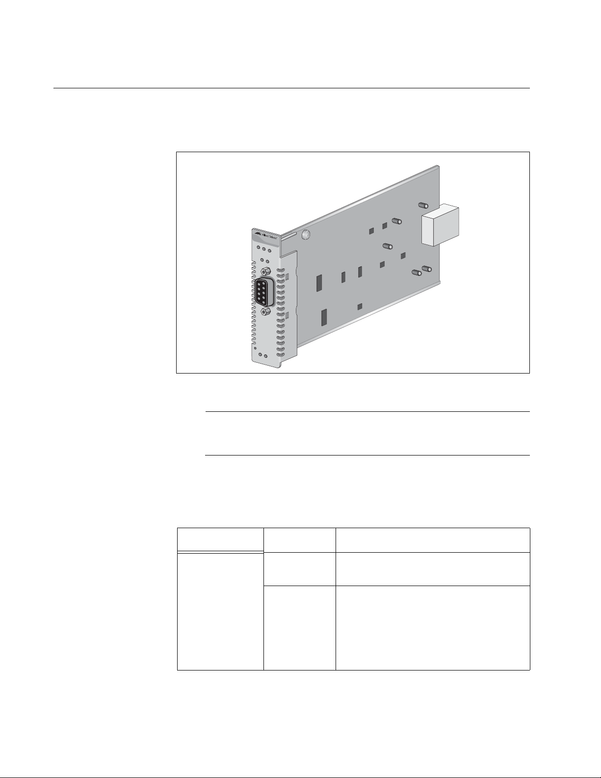
AT-CV5LED Card
The AT-CV5001 Chassis comes with the AT-CV5LED Card, shown in
Figure 5, installed in slot 19. This card is required in the chassis.
RDY FLT M
ASTER
PS-A PS-
B
RESET LINE
/SFM
FAN-A FAN-B
Figure 5. AT-CV5LED Card
The Console port and the RDY, FLT, and MASTER LEDs on the
card are for manufacturing purposes only.
The PS and FAN LEDs reflect the status of the power supplies in the
chassis and are described in Table 1.
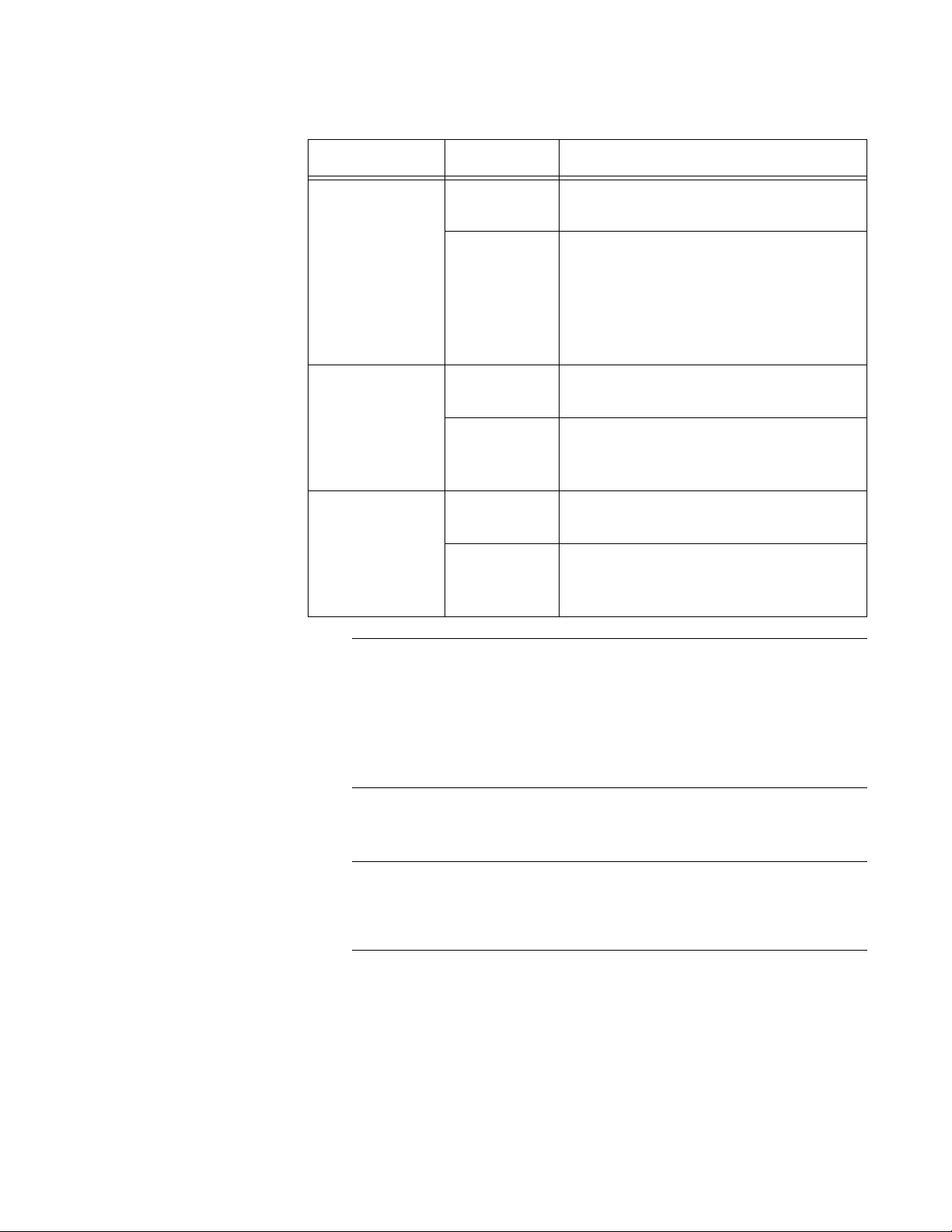
Table 1. Status LEDs on the AT-CV5LED Card
LED State Description
PS-A Green The power supply in slot A is
operating normally.
OFF The power supply in slot A is powered
off or has failed. The LED will also be
off if the slot is empty or if the input
power from the power source is
outside the operating range of the
power supply module.
24
Page 25
AT-CV5001 Media Converter Chassis Installation Guide
Note
Note
Table 1. Status LEDs on the AT-CV5LED Card (Continued)
LED State Description
PS-B Green The power supply in slot B is
operating normally.
OFF The power supply in slot B is powered
off or has failed. The LED will also be
off if the slot is empty or if the input
power from the power source is
outside the operating range of the
power supply module.
FAN-A Steady
Green
The fan in the power supply installed
in slot A is operating normally.
OFF The power supply in slot A fan has
failed, the fan has failed, or the slot is
empty.
FAN-B Steady
Green
The fan in the power supply installed
in slot B is operating normally.
OFF The power supply in slot B fan has
failed, the fan has failed, or the slot is
empty.
The card has a Reset button you can use to reset the AT-CV and
AT-CM2 Media Converter Cards in the chassis. The cards initialize
their management software. Resetting the line cards may result in
the loss of some network traffic. The reset button does not affect the
AT-CV5M02 Management Card or the AT-CM3 Media Converter
Cards.
The AT-CV5LED Card does not use management software.
The AT-CV5LED Card must only be serviced by an Allied Telesis
technician. If the card develops a problem, contact Allied Telesis for
assistance.
25
Page 26

Chapter 1: Overview
26
Page 27

Chapter 2
Installation
This chapter contains the following installation procedures for the
AT-CV5001 Chassis:
“Reviewing the Safety Precautions” on page 28
“Selecting a Site for the Chassis” on page 31
“Unpacking the Chassis” on page 32
“Installing the AT-CV5001 Chassis in a Rack” on page 34
“Grounding the AT-CV5001 Chassis” on page 36
“Installing the AT-CV5001AC Power Supply” on page 38
“Installing the AT-CV5001DC Power Supply” on page 43
“Installing the Media Converter Line Cards” on page 47
“Installing the AT-CV5M02 Management Card” on page 52
“Powering On an AC Powered Chassis” on page 57
“Powering On a DC Powered Chassis” on page 59
27
Page 28

Chapter 2: Installation
Note
Reviewing the Safety Precautions
Please review the following safety precautions before you begin to install
the chassis.
The indicates that a translation of the safety statement is
available in the PDF document titled “Translated Safety Statements”
(613-000405) on the Allied Telesis website at www.alliedtelesis.com
Warning: Class 1 Laser product.
Warning: Do not stare into the laser beam.
Warning: To prevent electric shock, do not remove the cover.
No user-serviceable parts inside. This unit contains hazardous
voltages and should only be opened by a trained and qualified
technician. To avoid the possibility of electric shock, disconnect
electric power to the product before connecting or disconnecting
the LAN cables.
Warning: Do not work on equipment or cables during pe riods of
lightning activity.
Warning: Class I Equipment. This equipment must be earthed.
The power plug must be connected to a properly wired earth
ground socket outlet. An improperly wired socket outlet could
place hazardous voltages on accessible metal parts.
E1
E2
L1
L2
E4
28
Pluggable Equipment. The socket outlet shall be installed near
E6
E5
E7
the equipment and shall be easily accessible.
Caution: Air vents must not be blocked and must have free
access to the room ambient air for cooling.
Warning: Operating Temperature. This prod uct is designed for a
maximum ambient temperature of 40° degrees C.
All Countries: Install product in accordance with local and
National Electrical Codes.
E8
Page 29

AT-CV5001 Media Converter Chassis Installation Guide
Warning: As a safety precaution, install a circuit breaker with a
minimum value of 15 Amps between the equipment and the DC
power source.
Always connect the wires to the LAN equipment first before you
connect the wires to the circuit breaker. Do not work with HOT
feeds to avoid the danger of physical injury from electrical shock.
Always be sure that the circuit breaker is in the OFF position
before connecting the wires to the breaker.
Warning: Do not strip more than the recommended amount of
wire. Stripping more than the recommended amount can create
a safety hazard by leaving exposed wire on the terminal block
after installation.
Warning: When installing this equipment, always ensure that the
frame ground connection is installed first and disconnected last.
E11
E10
E9
Warning: Check to see if there are any e xposed copper strands
coming from the installed wire. When this installation is done
correctly there should be no exposed copper wire strands
extending from the terminal block. Any exposed wiring can
conduct harmful levels of electricity to persons touching the
wires.
This system works with positive grounded or negative grounded
DC systems.
Circuit Overloading: Consideration should be given to the
connection of the equipment to the supply circuit and the effect
that overloading of circuits might have on overcurrent protection
and supply wiring. Appropriate consideration of equipment
nameplate ratings should be used when addressing this
concern.
Warning: For centralized DC power connection, install only in a
restricted access area.
A tray cable is required to connect the power source if the unit is
powered by centralized DC power. The tray cable must be a UL
listed Type TC tray cable and rated at 600 V and 90 degrees C,
with three conductors, minimum 14 AWG.
E12
E21
E13
E23
E24
29
Page 30

Chapter 2: Installation
Warning: Mounting of the equipment in the ra ck should be such
that a hazardous condition is not created due to uneven
mechanical loading.
Warning: Remove all metal jewelry, such as rings and watches,
before installing or removing a line card from a powered-on
chassis.
Warning: This unit might have more than one power source. To
reduce the risk of electric shock, disconnect all power sources
before servicing the unit.
If installed in a closed or multi-unit rack assembly, the operating
ambient temperature of the rack environment may be greater
than the room ambient temperature. Therefore, consideration
should be given to installing the equipment in an environment
compatible with the manufacturer’s maximum rated ambient
temperature (Tmra).
E26
E25
E35
E30
Caution: Installation of the equipment in a rack should be such
that the amount of air flow required for safe operation of the
equipment is not compromised.
Warning: Reliable earthing of rack-mounted equipment should
be maintained. Particular attention should be given to supply
connections other than direct connections to the branch circuits
(e.g., use of power strips).
Warning: Circuit breaker is used as a disconnection device. To
de-energize equipment, shut down the circuit breaker and then
disconnect the input wire.
E36
E37
E38
30
Page 31

Selecting a Site for the Chassis
Observe the following requirements when choosing a site for the chassis:
If you plan to install the chassis in an equipment rack, check to be sure
that the rack is safely secured and that it will not tip over. Devices in a
rack should be installed starting at the bottom, with the heavier d evices
near the bottom of the rack.
The chassis is heavy and requires three people to install it. For the
weight and dimensions of the chassis, see “Physical S pecifications” on
page 79.
If you are installing the chassis on a table, be sure that the table is
level and secure.
The power outlet for the chassis should be located near the unit and
should be easily accessible.
The site should provide easy access to the ports and connectors on
the front and the rear of the chassis, so that you can connect and
disconnect cables as well as to view the LEDs.
AT-CV5001 Media Converter Chassis Installation Guide
For proper cooling of the chassis, air flow around the unit and through
its vents should be unrestricted. Allow 8 inches around the rear of the
chassis for proper airflow.
Do not place objects on top of the chassis.
Do not expose the chassis to moisture or water.
Make sure that the site is a dust-free environment.
Use dedicated power circuits or power conditioners to supply reliable
electrical power to the device.
31
Page 32

Chapter 2: Installation
Note
Unpacking the Chassis
To unpack the chassis, perform the following procedure:
1. Remove all the components from the shipping package.
2. Make sure that the following components are included in the package.
If any item is missing or damaged, contact your Allied Telesis sales
representative for assistance.
Store the packaging material in a safe location. You must use the
original shipping material if you need to return the unit to Allied
Telesis.
Table 2. AT-CV5001 Chassis Components
One AT-CV5001 Chassis
AT-CV5001
Allied Telesis
R
DY
M
S
T
R
F
L
F
T
A
N
1
P
S
1
P
S
A
P
S
B
R
D
Y
R
E
S
E
T
L
I
N
E
/
S
F
M
FAN-A FAN
B
1648
One pre-installed AT-CV5LED
Card in slot 19
R
D
Y
F
L
T
M
A
S
T
E
R
P
S
-A
P
S
B
RESET LINE/SFM
F
A
N
-A
F
A
N
-B
Two rack-mounting brackets
1645
Eight flathead Phillips rackmounting bracket screws
32
Page 33

AT-CV5001 Media Converter Chassis Installation Guide
Note
222
Table 2. AT-CV5001 Chassis Components
One ground lug
1409
One line card removal tool
1137
Seventeen preinstalled
AT-CV5PNL1 slot covers on the
front panel
One preinstalled power supply slot
cover on slot B on the back panel
1643
The chassis does not come with a power supply. Power supplies
must be ordered separately.
3. Place the AT-CV5001 Chassis on a level, secure surface.
33
Page 34

Chapter 2: Installation
Installing the AT-CV5001 Chassis in a Rack
To install the chassis in a standard 19-inch equipment, perform the
following procedure:
1. Turn the chassis over and lay it on its top on a level, secure surface.
B
N
FA
-A
N
FA
P
X
/E
E
IN
L
T
E
S
E
R
Y
RD
PS-A PS-B
1
S
P
1
N
A
F
R
E
T
S
A
M
T
FL
Y
RD
17
18
16
14
15
13
12
Allied Telesis
AT-CV5001
11
10
8
9
6
7
5
3
2
4
1
1647
Figure 6. Removing the Feet
2. Using a flat-head screwdriver, pry off the rubber feet from the base of
the unit.
Figure 7. Removing the Feet
3. Turn the chassis right side up on the table.
34
Page 35

AT-CV5001 Media Converter Chassis Installation Guide
Caution
F
A
N
1
P
S
1
R
D
Y
RDY
M
S
T
R
F
L
T
R
E
S
E
T
L
IN
E
/S
F
M
PS-A PS-B
F
A
N
-A
FA
N
B
1661
4. Attach the brackets to the sides of the chassis using four screws
(provided) on each side, as shown in Figure 8
AT-CV5001
Allied Telesis
R
DY
M
S
T
R
F
L
F
T
AN
1
PS1
PS
A
P
S
B
R
D
Y
R
E
S
E
T
L
I
N
E
/
S
F
M
F
A
N
A
FA
N
B
1642
Figure 8. Installing the Brackets
5. Mount the chassis in the equipment rack using appropriate screws (not
provided), as shown in Figure 9.
The chassis is heavy. Physical injury may result if you attempt to
install the chassis without assistance. Two people should hold the
unit while a third person secures it to the rack.
Figure 9. Mounting the AT-CV5001 Chassis in a 19-inch Equipment Rack
35
Page 36

Chapter 2: Installation
Warning
A
1679
Grounding the AT-CV5001 Chassis
For safe and proper operation, the AT-CV5001 Chassis should be
grounded to a ground point in the wiring closet. Grounding the chassis
requires the following items:
One ground lug
One 12 AWG stranded wire or 14 AWG solid wire (not provided)
Crimping tool (not provided)
Cross-head screwdriver (not provided)
When installing this equipment, always ensure that the frame
ground connection is installed first and disconnected last. E11
To attach the frame ground, perform the following procedure:
1. Use a crimping tool to affix the ground lug to one end of the 12 AWG
stranded or 14 AWG solid ground wire, as shown in Figure 10.
1641
Figure 10. Connecting the Wire to the Ground Lug
2. Remove the two grounding screws from the rear panel of the
AT-CV5001 Chassis.
36
Figure 11. Removing the Grounding Lug Screws
Page 37

AT-CV5001 Media Converter Chassis Installation Guide
A
1658
3. Attach the grounding lug to the chassis with the screws removed in the
previous step.
Figure 12. Attaching the Grounding Lug to the Chassis
If you purchased the AT-CV5001AC Power Supply, go to the next
procedure. If you purchased the AT-CV5001DC Power Supply, go to
“Installing the AT-CV5001DC Power Supply” on page 43.
37
Page 38

Chapter 2: Installation
Note
Note
Note
A
T
C
V
5
0
0
1
A
C
D
IS
C
O
N
N
E
C
T
A
L
L
P
O
W
E
R
S
U
P
P
L
IE
S
&
R
E
F
E
R
T
O
M
A
N
U
A
L
B
E
F
O
R
E
S
E
R
V
IC
IN
G
.
1
0
0
2
4
0
V
A
C
~
1688
Installing the AT-CV5001AC Power Supply
The AT-CV5001AC Power Supply can be installed in either power supply
slot on the read panel.
The AT-CV5001 Chassis can contain two power supplies. The
power supplies can be of the same type (AC or DC) or different
types (AC and DC).
The power supply module is hot-swappable. If the chassis already
has a power supply that is powered on, you do not have to po wer off
the unit to install the new power supply module.
To install the AT-CV5001AC Power Supply, perform the following
procedure:
1. Remove the AT-CV5001AC Power Supply from its shipping package
and store the package in a safe place.
You must use the original package if you need to return the unit to
Allied Telesis.
2. Verify the package contents, listed in Table 3.
Table 3. AT-CV5001AC Power Supply Components
One AT-CV5001AC Power Supply
38
Page 39

AT-CV5001 Media Converter Chassis Installation Guide
Table 3. AT-CV5001AC Power Supply Components
Four regional power cords (North
America, Europe, Australia and
1694
1693
1692
1691
United Kingdom)
39
Page 40

Chapter 2: Installation
WAR
NING
This unit might h
a
ve more than one p
o
wer input.
T
o reduce the risk
of electric shock
, disconnect all power inputs bef
ore se
r
vicing unit
.
o
WA
R
NIN
G
This unit might h
a
ve more than one p
o
wer input
.
T
o reduce the risk
of electric shock, disconnect all power inputs before servicing unit.
o
B
1682
3. The power supply can be installed in either slot A or slot B. If this is the
initial installation and if you are installing just one power supply, Allied
Telesis recommends installing the module in slot A because that slot
does not have a cover. If you want to install the module in slot B,
remove the cover from the slot by loosening the two captive screws
with a cross-head screwdriver.
B
1681
40
Figure 13. Removing the Cover from Slot B
Page 41

AT-CV5001 Media Converter Chassis Installation Guide
Note
Note
A
WARNING
T
h
is
u
n
it m
ig
h
t h
a
v
e
m
o
re
th
a
n
o
n
e
p
o
w
e
r in
p
u
t
.
T
o
r
ed
u
c
e
th
e
ris
k
o
f e
le
c
tric s
h
o
c
k
, d
is
c
o
n
n
e
c
t a
ll p
o
w
e
r in
p
u
ts
b
e
f
o
re
s
e
r
v
ic
in
g
u
n
it
o
AT-CV5001A
C
DISCONNECT ALL P
O
WER SUPPLIES &
REFER
T
O MAN
UAL BEFORE SERVICING
.
100-240
VAC~
1656
Be sure to retain the slot cover and to reinstall it if you remove the
power supply from the unit. Open slots hamper the ability of the
cooling fan in the remaining power supply to maintain proper air
circulation in the chassis.
4. Orient the AT-CV5001AC Power Supply as shown in the figure and
gently slide the module into the slot until it is flush with the front of the
chassis.
Figure 14. Inserting the AT-CV5001AC Power Supply
Light pressure may be needed to seat the module on the power and
control pins on the backplane inside the chassis. Do not force the
module. You might bend the pins. If there is resistance, remove the
module and try again.
41
Page 42

Chapter 2: Installation
A
AT-CV5001AC
DISC
ONNECT A
LL PO
W
ER
S
UPPLIES &
R
EFER TO MANUA
L BE
FOR
E SER
V
IC
ING
.
100-240VA
C~
W
AR
NING
This unit might
h
a
ve more than
one p
o
wer input
.
To reduce the risk
of electric
shock,
disconnect
all power inputs be
fore servicing unit.
o
1686
5. Secure the AT-CV5001AC Power Supply to the chassis by tightening
the captive screws, as shown in Figure 15.
Figure 15. Securing the AT-CV5001AC Power Supply
To install a second AT-CV5001AC Power Supply, repeat this procedure.
For information about powering on an AC-powered chassis, refer to
“Powering On an AC Powered Chassis” on page 57.
42
Page 43

Installing the AT-CV5001DC Power Supply
Note
Note
Note
The AT-CV5001DC Power Supply can be installed in eith er slot A or slot B
on the read panel.
The AT-CV5001 Chassis can contain two power supplies. The
power supplies can be of the same type (AC or DC) or different
types (AC and DC).
The power supply module is hot-swappable. If the chassis already
has a power supply that is powered on, you do not have to power off
the unit to install the new power supply module.
To install the AT-CV5001DC Power Supply, perform the following
procedure:
AT-CV5001 Media Converter Chassis Installation Guide
1. Remove the AT-CV5001DC Power Supply from its shipping package
and store the package in a safe place.
You must use the original package if you need to return the unit to
Allied Telesis.
2. Verify the package contents.
Table 4. AT-CV5001DC Power Supply Component
One AT-CV5001DC Power Supply
AT-C
V
5
0
0
1
D
C
4
0
-6
0
V
D
C
FO
R CENTRALIZED
DC PO
W
ER
CO
NNECTIO
N,
D
INSTALL ONLY IN A
IS
C
O
N
N
E
C
T
R
A
RESTRICTED AR
E
L
F
L
E
P
R
O
TO
W
M
E
R
A
S
N
O
U
U
A
EA.
R
L
B
C
E
E
S
F
&
O
R
E
S
E
R
V
IC
IN
G
1690
43
Page 44

Chapter 2: Installation
WA
RNING
This unit might h
a
ve more than one p
o
wer input
.
T
o reduce the risk
of electric shock
, disconnect all power inputs before ser
vicing unit
.
o
WA
R
N
IN
G
This unit might h
a
ve more than one p
o
wer input
.
T
o reduce the risk
of electric shock, disconnect all power inputs before servicing unit.
o
B
1682
3. The power supply can be installed in either slot A or slot B. If this is the
initial installation and if you are installing just one power supply, Allied
Telesis recommends installing the module in slot A because that slot
does not have a cover. If you want to install the module in slot B,
remove the cover from the slot by loosening the two captive screws
with a cross-head screwdriver.
B
1681
44
Figure 16. Removing the Cover from Slot B
Page 45

AT-CV5001 Media Converter Chassis Installation Guide
Note
Note
A
A
W
ARNING
This unit might h
ave more than one power input.
T
o reduce the risk
of electric shoc
k, disconnect all power inputs before servicing unit.
o
AT-CV5001DC
FOR CENTRALIZED
RESTRICTED AREA.
INSTALL ONLY IN A
CONNECTION,
DC POWER
DISCONNECT ALL POWER SOURCES &
REFER TO MANUAL BEFORE SERVICING
40-60VDC
1657
Be sure to retain the slot cover and to reinstall it if you ever remove
the power supply from the unit. Open slots hamper the ability of the
cooling fan in the remaining power supply to maintain proper air
circulation in the chassis.
4. Orient the AT-CV5001DC Power Supply as shown in the figure and
gently slide the module into the slot until it is flush with the front of the
chassis.
Figure 17. Inserting the AT-CV5001DC Power Supply
Light pressure may be needed to seat the module on the power and
control pins on the backplane inside the chassis. Do not force the
module. You might bend the pins. If there is resistance, remove the
module and try again.
5. Secure the AT-CV5001DC Power Supply to the chassis by tightening
the captive screws, as shown in Figure 15.
45
Page 46

Chapter 2: Installation
A
AT-CV5001DC
FOR CENTRALIZED
RESTRICTED AREA.
INSTALL ONLY IN A
CONNECTION,
DC POWER
W
AR
NING
T
his un
it m
ig
h
t
h
a
ve m
o
re
th
a
n
o
n
e pow
e
r in
pu
t
.
To re
du
ce
th
e
risk
o
f e
lectric
sh
ock
,
dis
c
onn
ect
all p
o
w
er in
p
u
ts
b
e
fo
r
e se
rvicing
un
it
o
D
ISCON
NECT ALL PO
W
ER SOU
RC
ES &
REFER TO M
ANU
AL BEFORE SER
VICING
40-60VDC
1687
Figure 18. Securing the AT-CV5001DC Power Supply
To install a second AT-CV5001DC Power Supply, repeat this procedure.
For information about powering on a DC-powered chassis, refer to
“Powering On a DC Powered Chassis” on page 59.
46
Page 47

Installing the Media Converter Line Cards
Note
This section contains general instructions on how to install the media
converter line cards. For specific instructions, refer to the Installation
Guides that come with the cards.
Warning: Remove all metal jewelry, such as rings and watches,
before installing or removing a line card from a powered-on
chassis.
Caution Be sure to observe all standard electrostatic discharge
(ESD) precautions, such as wearing an antistatic wrist strap, to
avoid damaging the device. A line card can be damaged by
static electricity.
To install a Converteon line card, perform the following procedure:
E26
AT-CV5001 Media Converter Chassis Installation Guide
1. Remove the Converteon line card from its shipping package and store
the package in a safe place.
You must use the original package if you need to return the unit to
Allied Telesis.
2. Remove the slot cover from an empty slot in the chassis by loosening
the captive screw. The media converter line cards can be installed in
any of the slots and in any order. Allied Telesis recommends installing
the first line card in slot 1 because that slot does not have a cover. If
you are installing the double-slot AT-CM70S Line Card, you must
remove two adjacent slot covers.
47
Page 48

Chapter 2: Installation
Note
257
Figure 19. Removing a Blank Slot Cover
Be sure to retain the slot cover and to reinstall it if you remove the
media converter line card from the unit. Open slots hamper the
ability of the cooling fan in the power supply to maintain proper air
circulation in the chassis.
48
Page 49

AT-CV5001 Media Converter Chassis Installation Guide
Alignment Guides
Alignment Guides
3. Set the card’s DIP switches to set the operating mode and, in the case
of an AT-CV Card, the operating configuration of the 10/100Base-TX
twisted pair port. For descriptions of the operating modes, refer to the
AT-S73, AT-S99, and AT-S102 Management Software User’s Guide.
For instructions on how to set the DIP switches, refer to Installation
Guide that comes with the card.
4. Locate the top and bottom alignment guides inside the line card slots.
7 86 9 10 11 12 13
5. Align the line card with the top and bottom alignment guides located
inside the slot.
6. Slide the line card into the slot, as shown in Figure 21, until the front of
the card is flush with the front of the chassis.
290
Figure 20. Alignment Guides
49
Page 50

Chapter 2: Installation
AT-CM302
LK
A
T
T
X
RD
Y
LK
AT FD
T
X
M
M
R
X
LPM
10/100/1000
SML
ML OAM
100M
1651
A
T
-CM302
LK
A
T
T
X
R
D
Y
LK
AT FD
T
X
M
M
R
X
LPM
10/100/1000
SML
ML OAM
100M
1650
Figure 21. Inserting a Line Card
7. Use a Phillips screwdriver to tighten the captive screw on the card to
secure the card to the chassis.
50
Figure 22. Tightening the Captive Screw
Page 51

AT-CV5001 Media Converter Chassis Installation Guide
8. Repeat this procedure to install additional line cards.
9. After installing the media converter cards, refer to their Installation
Guides for cabling instructions.
51
Page 52

Chapter 2: Installation
Note
Installing the AT-CV5M02 Management Card
This section contains the instructions for installing the AT-CV5M02
Management Card.
Warning: Remove all metal jewelry, such as rings and watches,
before installing or removing a line card from a powered-on
chassis.
Caution Be sure to observe all standard electrostatic discharge
(ESD) precautions, such as wearing an antistatic wrist strap, to
avoid damaging the device. A line card can be damaged by
static electricity.
Note
The AT-CV5001 Chassis does not support the AT-CV5M01
Management Card.
E26
To install the AT-CV5M02 Management Card, perform the following
procedure:
1. Select a slot in the chassis for the management card. You can install
the card in any slot.
If you are installing a redundant management card into an existing
chassis, you should install it while the chassis is powered on. If the
chassis is powered off, you should install it in a higher numbered slot
than the existing management card. If you install a redundant
management card into a lower numbered slot than the existing card
while the chassis is powered off, the master configuration file of the
new card, which will become the active card, will overwrite the
configuration file on the existing card when you power on the
chassis. If the auto-copy settings in the new master configuration file
is enabled for the chassis slots, the configuration settings of the line
cards may change. For further information, refer to Converteon
AT-S73, AT-S99, AT-S102, Management Software User’s Guide.
52
Page 53

AT-CV5001 Media Converter Chassis Installation Guide
Note
AT-CM302
LK
AT
T
X
RDY
LK
A
T FD
T
X
M
M
R
X
LPM
10/100/1000
SML
ML O
AM
100M
AT-CM302
LK
AT
T
X
RDY
LK
A
T FD
T
X
M
M
R
X
LPM
10/100/1000
SML
ML O
AM
100M
AT-CM302
LK
AT
T
X
RDY
LK
A
T FD
T
X
M
M
R
X
LPM
10/100/1000
SML
ML O
AM
100M
AT-CM302
LK
AT
T
X
RDY
LK
A
T FD
T
X
M
M
R
X
LPM
10/100/1000
SML
ML O
AM
100M
AT-CM302
LK
AT
T
X
RDY
LK
A
T
FD
T
X
M
M
R
X
LP
M
10/100/100
0
SML
ML OAM
100M
AT-CM302
LK
AT
T
X
RDY
LK
A
T
FD
T
X
M
M
R
X
LP
M
10/100/1000
SML
ML OAM
100M
AT-CM302
LK
AT
T
X
RDY
LK
A
T
F
D
T
X
M
M
R
X
L
PM
10/100/1000
SML
ML OAM
100M
AT-CM302
LK
AT
T
X
RDY
LK
A
T
FD
T
X
M
M
R
X
L
PM
10/100/1000
SML
ML OAM
100M
1684
2. Remove the slot cover from an empty slot in the chassis by loosening
the captive screw.
1683
Figure 23. Removing a Slot Cover
Be sure to retain the slot cover and to reinstall it if you remove the
management card from the unit. Open slots hamper the ability of the
cooling fan in the power supply to maintain proper air circulation in
the chassis.
53
Page 54

Chapter 2: Installation
Note
1405
1. Remove the AT-CV5M02 Management Card from its shipping
package and store the package in a safe place.
You must use the original package if you need to return the unit to
Allied Telesis.
2. Verify the package contents.
Table 5. AT-CV5M02 Management Card Components
One AT-CV5M02 Management
Card
AT-CV5M02
PWR RDY FLT
LK AT FD
C
P
U
R
E
S
E
T
240
One management cable with DB-9
connectors
1417
One fold-out Management Card
Allied Telesis
Installation Guide
One documentation CD
54
Page 55

AT-CV5001 Media Converter Chassis Installation Guide
AT-CM302
LK
AT
T
X
RDY
LK
AT FD
T
X
M
M
R
X
LPM
10/100/1000
SM
L
M
L OAM
100M
AT-CM302
LK
AT
T
X
RDY
LK
AT FD
T
X
M
M
R
X
LPM
10/100/1000
SML
M
L OAM
100M
AT-CM302
LK
AT
T
X
RDY
LK
AT FD
T
X
M
M
R
X
LPM
10/100/1000
SM
L
M
L OAM
100M
AT-CM302
LK
AT
T
X
RDY
LK
AT FD
T
X
M
M
R
X
LPM
10/100/1000
SM
L
ML OAM
100M
AT-CV5M02
PW
R RD
Y FL
T
C
P
U
R
E
S
E
T
LK AT FD
3. Align the line card with the top and bottom alignment guides for the slot
(Figure 20 on page 49).
4. Slide the card into the slot until the front panel of the card is flush with
the front of the chassis.
1654
Figure 24. Installing the AT-CV5M02 Management Card
5. Use a Phillips screwdriver to tighten the captive screw to secure the
card to the chassis, as shown in Figure 25.
55
Page 56

Chapter 2: Installation
AT-CM302
LK
AT
T
X
RDY
LK
AT FD
T
X
M
M
R
X
LPM
10/100/1000
SML
ML OAM
100M
AT-CM302
LK
AT
T
X
RDY
LK
AT FD
T
X
M
M
R
X
LPM
10/100/1000
SML
ML OAM
100M
AT-CM302
LK
AT
T
X
RDY
LK
AT FD
T
X
M
M
R
X
LPM
10/100/1000
SML
ML OAM
100M
AT-CM302
LK
AT
T
X
RDY
LK
AT FD
T
X
M
M
R
X
LPM
10/100/1000
SML
ML OAM
100M
1655
AT-CV5M02
PWR RDY FLT
LK AT FD
CPU RESET
Figure 25. Tightening the Captive Screw
6. If the chassis will have a redundant management card, repeat this
procedure to install the second card.
7. After installing the management card, refer to the Management Card
Installation Guide for cabling instructions.
56
Page 57

Powering On an AC Powered Chassis
Note
A
AT-CV5001AC
D
IS
C
O
N
N
E
C
T
A
L
L
P
O
W
E
R
S
U
P
P
L
IE
S
&
R
E
F
E
R
T
O
M
A
N
U
A
L
B
E
F
O
R
E
S
E
R
V
IC
IN
G
.
100-2
40V
A
C
~
1646
This section describes how to power on an AC powered AT-CV5001
Chassis.
To power on an AC powered chassis, perform the following procedure:
1. Select the power cord for your region: North America, United Kingdom,
Europe, or Australia.
2. Plug the power cord into the AC power connector on the rear of the
chassis, as shown in Figure 26.
AT-CV5001 Media Converter Chassis Installation Guide
Figure 26. Connecting the AC Power Cord
3. Plug the other end of the power cord to an appropriate power outlet.
If the chassis has two AT-CV5001AC Power Supplies, repeat this
procedure to power on the second module.
Refer to “Technical Specifications” on page 79 for the power
requirements.
If the chassis has two power supplies, you can protect the unit from
a power circuit failure by connecting the two power supplies to
power sources that are operating on different power circuits.
57
Page 58

Chapter 2: Installation
Warning
Warning
This unit might have more than one power source. To reduce the
risk of electric shock, disconnect all power cords before servicing the
unit. E30
Class I Equipment. This equipment must be earthed. The power
plug must be connected to a properly wired earth ground socket
outlet. An improperly wired socket outlet could place hazardous
voltages on accessible metal parts. E4
4. Check the PS-A, PS-B, FAN-A and FAN-B LEDs on the AT-CV5LED
Card in slot 19. The appropriate LEDs should be on. For LED
definitions, refer to Table 1, ”Status LEDs on the AT-CV5LED Card” on
page 24. If an LED is off, refer to “Troubleshooting” on page 77 for
instructions.
The chassis is now ready for network operations.
58
Page 59

Powering On a DC Powered Chassis
A
FOR CENTRALIZED
RESTRICTED AREA.
INSTALL ONLY IN A
CONNECTION,
DC POWER
AT-CV5001DC
DISCONNECT ALL POWER SOURCES &
REFER TO MANUAL BEFORE SERVICING
40-60VDC
1689
+48 VDC Positive
Ground -48 VDC Negative
TerminalTerminal
Terminal
This section describes how to power on a DC powered AT-CV5001
Chassis. If your chassis is AC powered, see “Powering On an AC
Powered Chassis” on page 57. For information on how to install the power
supply, refer to “Installing the AT-CV5001DC Power Supply” on page 43.
Warning: As a safety precaution, install a circuit breaker with a
minimum value of 15 Amps between the equipment and the DC
power source.
Always connect the wires to the LAN equipment first before you
connect the wires to the circuit breaker. Do not work with HOT
feeds to avoid the danger of physical injury from electrical shock.
Always be sure that the circuit breaker is in the OFF position
before connecting the wires to the breaker.
AT-CV5001 Media Converter Chassis Installation Guide
E9
Warning: For centralized DC power connection, install only in a
restricted access area.
A tray cable is required to connect the power source if the unit is
powered by centralized DC power. The tray cable must be a UL
listed Type TC tray cable and rated at 600 V and 90 degrees C,
with three conductors, minimum 14 AWG.
1. Power off the DC circuit you plan to use for the chassis.
2. Use the legend next to the terminal block to identify the terminals. The
terminals are positive, power supply ground and negative, from
right to left.
E23
E24
Figure 27. DC Terminal Block on the AT-CV5001DC Power Supply
Module
59
Page 60

Chapter 2: Installation
Warning
Warning
A
FOR CENTRALIZED
RESTRICTED AREA.
INSTALL ONLY IN A
CONNECTION,
DC POWER
AT-CV5001DC
DISCONNECT ALL POW
ER SOURCES &
REFER TO MANU
AL BEFORE SER
VICING
40-60VDC
1640
3. With a 14-gauge wire-stripping tool, strip the three wires in the tray
cable coming from the DC input power source to 8mm 1mm (0.31 in.,
0.039 in.), as shown in Figure 28 on page 60.
Do not strip more than the recommended amount of wire. Stripping
more than the recommended amount can create a safety hazard by
leaving exposed wire on the terminal block after installation. E10
8mm ±1mm
(0.31in. ±0.039in.)
Figure 28. Stripped Wire
4. Insert the power supply ground wire into the middle connector of the
DC terminal and tighten the connection with a flathead screwdriver, as
shown in Figure 29.
When installing this equipment, always ensure that the power supply
ground connection is installed first and disconnected last. E11
Figure 29. Inserting Wires into a DC Terminal Block
60
5. Connect the +48 VDC (RTN) feed wire to the terminal block marked
+ (plus).
Page 61

AT-CV5001 Media Converter Chassis Installation Guide
Note
Warning
6. Connect the -48 VDC feed wire to the terminal block marked - (minus).
Warning: Check to see if there are any exposed copper strands
coming from the installed wires. When this installation is done
correctly there should be no exposed copper wire strands
extending from the terminal block. Any exposed wiring can conduct harmful levels of electricity to persons touching the wires.
E12
7. Secure the tray cable near the rack framework using multiple cable ties
to minimize the chance of the connections being disturbed by casual
contact with the wiring. Use at least four cable ties, separated four
inches apart. Locate the first one within six inches of the terminal
block.
This system will work with a positive grounded or negative
grounded DC system. E13
8. Verify that the circuit breaker is in the OFF position.
9. Connect the supply-cable wires to the circuit breaker.
10. Energize the circuit breaker.
11. If you installed a second AT-CV5001DC Power Supply, repeat this
procedure.
If the chassis has two power supplies, you can protect the unit from
a power circuit failure by connecting the two power supplies to
power sources that are operating on different power circuits.
This unit might have more than one power source. To reduce the
risk of electric shock, disconnect all power cords before servicing the
unit. E30
12. Check the PS-A, PS-B, FAN-A and FAN-B LEDs on the AT-CV5LED
Card in slot 19. The appropriate LEDs should be on. For LED
definitions, refer to Table 1, ”Status LEDs on the AT-CV5LED Card” on
page 24. If an LED is off, refer to “Troubleshooting” on page 77 for
instructions.
The chassis is now ready for network operations.
61
Page 62

Chapter 2: Installation
62
Page 63

Chapter 3
Removing or Replacing Line Cards or Power Supply Modules
This chapter contains the following procedures:
“Removing or Replacing Media Converter Line Cards” on page 64
“Removing or Replacing the AT-CV5001AC Power Supply” on page 69
“Removing or Replacing the AT-CV5001DC Power Supply” on page 73
63
Page 64

Chapter 3: Removing or Replacing Line Cards or Power Supply Modules
Caution
AT-CM302
LK
AT
T
X
RDY
LK
AT FD
T
X
M
M
R
X
LPM
10/100/1000
SML
ML OAM
100M
AT-CM302
LK
AT
T
X
RDY
LK
AT FD
T
X
M
M
R
X
LPM
10/100/1000
SML
ML OAM
100M
AT-CM302
LK
AT
T
X
RDY
LK
AT FD
T
X
M
M
R
X
LPM
10/100/1000
SML
ML OAM
100M
AT-CM302
LK
AT
T
X
RDY
LK
AT FD
T
X
M
M
R
X
LPM
10/100/1000
SML
ML OAM
100M
AT-CM302
LK
AT
T
X
RDY
LK
AT FD
T
X
M
M
R
X
LPM
10/100/1000
SML
ML OAM
100M
Removing or Replacing Media Converter Line Cards
All of the Converteon media converter line cards are hot-swappable and
can be removed or installed while the chassis is powered on.
To remove or replace a media converter line card, perform the following
procedure:
Be sure to observe all standard electrostatic discharge (ESD)
precautions, such as wearing an antistatic wrist strap, to avoid
damaging the device. A line card can be damaged by static
electricity.
1. Label and disconnect the network cables from the card.
64
AT-CM302 slot 12
AT-CM302 slot 12
1663
Figure 30. Labeling and Removing the Network Cables
Page 65

AT-CV5001 Media Converter Chassis Installation Guide
AT-CM302
LK
AT
T
X
RDY
LK
AT FD
T
X
M
M
R
X
LPM
10/100/1000
SML
ML OAM
100M
AT-CM302
LK
AT
T
X
RDY
LK
AT FD
T
X
M
M
R
X
LPM
10/100/1000
SML
ML OAM
100M
AT-CM302
LK
AT
T
X
RDY
LK
AT FD
T
X
M
M
R
X
LPM
10/100/1000
SML
ML OAM
100M
AT-CM302
LK
AT
T
X
RDY
LK
AT FD
T
X
M
M
R
X
LPM
10/100/1000
SML
ML OAM
100M
AT-CM302
LK
AT
T
X
RDY
LK
AT FD
T
X
M
M
R
X
LPM
10/100/1000
SML
ML OAM
100M
1664
AT-CM302
LK
AT
T
X
RDY
LK
AT FD
T
X
M
M
R
X
LPM
10/100/1000
SML
ML OAM
100M
AT-CM302
LK
AT
T
X
RDY
LK
AT
FD
T
X
M
M
R
X
LPM
10/100/1000
SML
ML OAM
100M
AT-CM3KOS
LK
AT
T
X
RDY
LK
A
T
LPM
10/100/1000
SML
ML OAM
100M
AT-CM302
LK
AT
T
X
RDY
LK
AT FD
T
X
M
M
R
X
LPM
10/100/1000
SML
ML OAM
100M
AT-CM302
LK
AT
T
X
RDY
LK
AT FD
T
X
M
M
R
X
LPM
10/100/1000
SML
ML OAM
100M
S
FP
FD
1000M
1665
2. Cover the fiber optic port with a dust cap.
Figure 31. Installing the Dust Cap
3. If the card has an SFP module that needs to be installed in the
replacement card, remove the SFP module.
Figure 32. Removing the SFP Module
65
Page 66

Chapter 3: Removing or Replacing Line Cards or Power Supply Modules
AT-CM302
LK
AT
T
X
RDY
LK
AT FD
T
X
M
M
R
X
LPM
10/100/1000
SML
ML OAM
100M
AT-CM302
LK
AT
T
X
RDY
LK
AT FD
T
X
M
M
R
X
LPM
10/100/1000
SML
ML OAM
100M
AT-CM302
LK
AT
T
X
RDY
LK
AT FD
T
X
M
M
R
X
LPM
10/100/1000
SML
ML OAM
100M
AT-CM302
LK
AT
T
X
RDY
LK
AT FD
T
X
M
M
R
X
LPM
10/100/1000
SML
ML OAM
100M
AT-CM302
LK
AT
T
X
RDY
LK
AT FD
T
X
M
M
R
X
LPM
10/100/1000
SML
ML OAM
100M
1666
4. Using a Phillips screwdriver, loosen the captive screw at the top of the
line card.
Figure 33. Loosening the Captive Screw
66
Page 67

AT-CV5001 Media Converter Chassis Installation Guide
AT-CM302
LK
AT
T
X
RDY
LK
AT FD
T
X
M
M
R
X
LPM
10/100/1000
SML
ML OAM
100M
AT-CM302
LK
AT
T
X
RDY
LK
AT FD
T
X
M
M
R
X
LPM
10/100/1000
SML
ML OAM
100M
AT-CM302
LK
AT
T
X
RDY
LK
AT FD
T
X
M
M
R
X
LPM
10/100/1000
SML
ML OAM
100M
AT-CM302
LK
AT
T
X
RDY
LK
AT FD
T
X
M
M
R
X
LPM
10/100/1000
SML
ML OAM
100M
AT-CM302
LK
AT
T
X
RDY
LK
AT FD
T
X
M
M
R
X
LPM
10/100/1000
SML
ML OAM
100M
AT-CM302
LK
AT
T
X
RDY
LK
AT FD
T
X
M
M
R
X
LPM
10/100/1000
SML
ML OAM
100M
AT-CM302
LK
AT
T
X
RDY
LK
AT FD
T
X
M
M
R
X
LPM
10/100/1000
SML
ML OAM
100M
AT-CM302
LK
AT
T
X
RDY
LK
AT FD
T
X
M
M
R
X
LPM
10/100/1000
SML
ML OAM
100M
AT-CM302
LK
AT
T
X
RDY
LK
AT FD
T
X
M
M
R
X
LPM
10/100/1000
SML
ML OAM
100M
AT
-CM302
LK
A
T
T
X
RDY
LK
A
T FD
T
X
M
M
R
X
L
P
M
10/100/1000
SML
ML OAM
100M
5. Hook the slot at the end of the removal tool included with the chassis
onto the captive screw at the top of the line card, and pull towa rds you
to remove the card from the chassis, as shown in Figure 34.
1667
1668
6. If you are replacing the card, go to “Installing the Media Converter Line
Cards” on page 47 for instructions.
Figure 34. Removing a Line Card
67
Page 68

Chapter 3: Removing or Replacing Line Cards or Power Supply Modules
Note
AT-CM302
LK
AT
T
X
RDY
LK
A
T
FD
T
X
M
M
R
X
LP
M
10/1
00/1000
SML
ML OAM
100M
AT-CM302
LK
AT
T
X
RDY
LK
A
T
FD
T
X
M
M
R
X
LP
M
10/100/1000
SML
ML OAM
100M
AT-CM302
LK
AT
T
X
RDY
LK
A
T
FD
T
X
M
M
R
X
L
P
M
10/100/100
0
SML
ML OAM
100M
AT-CM302
LK
AT
T
X
RDY
LK
A
T
FD
T
X
M
M
R
X
L
P
M
10/100/1000
SML
ML OAM
100M
AT-CM302
LK
AT
T
X
RDY
LK
AT FD
T
X
M
M
R
X
LPM
10/100/1000
SML
ML OAM
100M
AT-CM302
LK
AT
T
X
RDY
LK
AT FD
T
X
M
M
R
X
LPM
10/100/1000
SML
ML OAM
100M
AT-CM302
LK
AT
T
X
RDY
LK
AT FD
T
X
M
M
R
X
LPM
10/100/1000
SML
ML OAM
100M
AT-CM302
LK
AT
T
X
RDY
LK
AT FD
T
X
M
M
R
X
LPM
10/100/1000
SML
ML OAM
100M
1670
7. If you are not replacing the card, install a blank slot cover in the empty
slot and secure it by tightening its captive screw.
68
1669
Do not operate the chassis with open slots. Open slots hamper the
ability of the cooling fan in the power supply to maintain proper air
circulation in the chassis.
Page 69

AT-CV5001 Media Converter Chassis Installation Guide
Note
A
A
T-CV5001
AC
DISCONNECT ALL
PO
WER SUPPLIES &
REFER
T
O MAN
U
AL BEFORE SE
RVICING
.
100-240VAC~
A
W
A
R
N
IN
G
This unit
might h
a
ve more than one p
o
wer input
.
T
o reduce
t
of electric shoc
k, disconnect all po
wer inputs before ser
vicin
o
1671
Removing or Replacing the AT-CV5001AC Power Supply
The AT-CV5001AC Power Supply is hot-swappable. You do not have to
power off the chassis to install a second power supply or to replace a
failed power supply in a chassis that has two power supplies.
There are two power supply slots. This procedure illustrates slot A. The
procedure is the same for slot B.
The predecessor to the AT-CV5001 Chassis, the AT-CV5000
Chassis, had different power supply modules for the left and right
slots. This is not the case for the AT-CV5001AC Power Supply,
which can be installed in either power supply slot in the AT-CV5001
Chassis.
To remove or replace the AT-CV5001AC Power Supply, perform the
following procedure.
1. Disconnect the power cord from the power source.
2. Disconnect the power cord from the AT-CV5001AC Power Supply.
Figure 35. Removing the Power Cord from the AT-CV5001AC Power
Supply
69
Page 70

Chapter 3: Removing or Replacing Line Cards or Power Supply Modules
A
A
T
-CV5001AC
DISCONNECT ALL PO
WER SUPP
LIES &
REFER
T
O MANU
AL BEFORE
SE
RVICING
.
100-240VAC~
AT
W
ARNING
This unit might h
a
ve more
than one
p
o
wer input.
T
o reduce
th
of electric shoc
k, disconnect all po
wer inputs be
f
ore servicing
o
1672
3. Using a Phillips screwdriver, loosen the two captive screws on the
module.
Figure 36. Loosening the Captive Screws on the AT-CV5001AC Power
Supply
4. Gently slide the module from the unit.
70
Page 71

AT-CV5001 Media Converter Chassis Installation Guide
Note
A
A
W
ARNING
This
unit
m
ight h
ave m
ore
th
an one
p
o
w
er in
put
.
T
o
re
du
ce
of electric shoc
k,
disconn
ect all p
o
w
e
r in
puts be
f
ore
se
r
vici
o
AT
-CV5001
A
C
D
IS
C
O
N
N
EC
T
A
L
L
P
O
W
E
R
S
U
P
P
L
IE
S
&
R
E
F
E
R
T
O
M
A
N
U
A
L
B
E
F
O
R
E
S
E
R
V
IC
IN
G
.
100-240
VAC~
1673
Figure 37. Removing the AT-CV5001AC Power Supply
Use care when pulling the power supply from the chassis. If you
roughly pull the module from the unit, you might bend the power and
control pins on the connectors on the backplane.
5. To install a new module, refer to “Installing the AT-CV5001AC Power
Supply” on page 38.
6. If you are not installing a new module, install the slot cover and secure
it to the chassis by tightening the captive screws.
71
Page 72

Chapter 3: Removing or Replacing Line Cards or Power Supply Modules
Note
A
A
W
ARN
ING
Th
is unit
m
ight have m
ore
than o
ne
p
o
w
er in
pu
t.
T
o reduc
e
t
of electri
c sho
c
k
, discon
ne
ct all p
o
we
r in
put
s be
f
ore se
r
vicin
o
1674
A
A
W
A
R
N
IN
G
This unit m
ight ha
ve m
ore
than one
p
o
wer input
.
T
o reduce t
of electri
c sho
ck
, disconne
ct all p
o
wer inputs be
fore servicin
o
1675
72
Figure 38. Installing the Slot Cover
Do not operate the chassis with open slots. Open slots hamper the
ability of the cooling fan in the power supply to maintain proper air
circulation in the chassis.
Page 73

AT-CV5001 Media Converter Chassis Installation Guide
Note
Warning
A
FOR CENTRALIZED
RESTRICTED AREA.
INSTALL ONLY IN A
CONNECTION,
DC POWER
AT-CV5001DC
DISCONNECT ALL POWER SOURCES &
REFER TO MANUAL BEFORE SERVICING
40-60VDC
1676
+48 VDC Positive
Ground -48 VDC Negative
TerminalTerminal
Terminal
Removing or Replacing the AT-CV5001DC Power Supply
The AT-CV5001DC Power Supply is hot-swappable. You do not have to
power off the chassis to install a second power supply or to replace a
failed power supply in a chassis that has two power supplies.
The predecessor to the AT-CV5001 Chassis, the AT-CV5000
Chassis, had different power supply modules for the left and right
slots. This is not the case for this chassis and the AT-CV5001DC
Power Supply, which can be installed in either slot.
There are two power supply slots. This procedure illustrates slot A. The
procedure is the same for slot B.
To remove or replace the AT-CV5001DC Power Supply, perform the
following procedure.
1. Power off the DC circuit to the AT-CV5001DC Power Supply
2. Disconnect the -48 VDC feed wire from the terminal block marked
- (minus).
3. Disconnect the +48 VDC (RTN) feed wire from the terminal block
marked + (plus).
4. Disconnect the power supply ground wire.
When installing this equipment, always ensure that the power supply
ground connection is installed first and disconnected last. E11
73
Page 74

Chapter 3: Removing or Replacing Line Cards or Power Supply Modules
A
AT-CV5001DC
FOR CENTRALIZED
RESTRICTED AREA.
INSTALL ONLY IN A
CONNECTION,
DC POWER
W
ARNING
T
his un
it m
ig
ht
h
a
ve m
o
re th
an
o
n
e pow
er in
pu
t
.
To redu
ce
the
risk
of e
le
ctric
s
h
oc
k,
disco
nn
ect
a
ll p
ow
e
r inp
u
ts b
e
fo
r
e
serv
icin
g u
nit.
o
D
ISCON
NECT ALL PO
W
ER SOUR
CES &
REFER TO M
AN
UAL BEFORE SER
VICING
40-60VD
C
1677
5. Using a Phillips screwdriver, loosen the two captive screws on the
module.
Figure 39. Loosening the Captive Screws on the AT-CV5001AC Power
Supply
74
Page 75

AT-CV5001 Media Converter Chassis Installation Guide
Note
A
A
WARNING
This unit might have more than one p
o
wer input
.
T
o reduce the risk
of electric sho
c
k, disconnect all po
wer inputs bef
ore se
rvicing unit
.
o
AT-CV5001DC
F
O
R
C
E
N
T
R
A
L
IZ
ED
R
E
S
TR
IC
TE
D
A
R
E
A
.
IN
STAL
L O
N
LY IN
A
C
O
N
NE
C
TIO
N
,
D
C
POW
ER
DISCONNECT ALL PO
WER SOURCES &
REFER TO MANUAL BEFORE SERVICING
40-60VDC
1678
6. Gently slide the module from the unit.
Figure 40. Removing the AT-CV5001AC Power Supply
Use care when pulling the power supply from the chassis. If you
roughly pull the module from the unit, you might bend the power and
control pins on the backplane connectors.
7. To install a new module, refer to “Installing the AT-CV5001AC Power
Supply” on page 38.
8. If you are not installing a new module, install the slot cover and secure
it to the chassis by tightening the captive screws.
75
Page 76

Chapter 3: Removing or Replacing Line Cards or Power Supply Modules
Note
A
A
W
ARN
ING
Th
is unit
m
ight have m
ore
than o
ne
p
o
w
er in
pu
t.
T
o reduc
e
t
of electri
c sho
c
k
, discon
ne
ct all p
o
we
r in
put
s be
f
ore se
r
vicin
o
1674
A
A
W
A
R
N
IN
G
This unit m
ight ha
ve m
ore
than one
p
o
wer input
.
T
o reduce t
of electri
c sho
ck
, disconne
ct all p
o
wer inputs be
fore servicin
o
1675
76
Figure 41. Installing the Slot Cover
Do not operate the chassis with open slots. Open slots hamper the
ability of the cooling fan in the power supply to maintain proper air
circulation in the chassis.
Page 77

Chapter 4
Note
Troubleshooting
This chapter contains information on how to troubleshoot the power supply
modules in the event a problem occurs.
If after following the instructions in this chapter you are unable to
resolve the problem, contact Allied Telesis Technical Support for
assistance. Refer to “Contacting Allied Telesis” on page 14 for
contact information.
The operational status of a power supply module is displayed on the PS
and FAN LEDs on the AT-CV5LED Card installed in slot 19 on the front
panel. PS-A and FAN-A LEDs correspond to slot A on the back panel and
PS-B and FAN-B LEDs correspond to slot B. If a power supply is operating
normally, both the PS LED and the FAN LED will be on. If one or both of
them are off, try the following:
Verify that the module is fully seated in the power supply slot in the
chassis.
Verify that the power cord is firmly connected to the power supply
module and the power source.
Try connecting the power module to another power source, preferably
located on a different circuit.
Verify that the power source is operating properly by plugging a
different device into it.
Verify that the power from the power source meets the operating
specifications of the power supply module, listed in “Power
Specifications” on page 79.
Replace the power supply module.
77
Page 78

Chapter 4: Troubleshooting
78
Page 79

Appendix A
Technical Specifications
Physical Specifications
Dimensions (W x D x H) 34.25 cm x 44.05 cm x 8.68 cm
Weight: 6.12 kg (13.5 lbs.)
Recommended Minimum Ventilation
on All Sides 10 cm (4.0 in)
Environmental Specifications
(13.49 in x 17.35 in x 3.42 in)
Operating Temperature: 0° C to 40° C (32° F to 104° F)
Storage Temperature: -25° C to 70° C (-13°F to 158° F)
Operating Humidity: 5% to 90% non-condensing
Storage Humidity: 5% to 95% non-condensing
Maximum Operating Altitude: 3,000 m (10,000 ft.)
Maximum Storage Altitude: 4,000 m (13,100 ft.)
Power Specifications
AT-CV5001AC
Power Supply
Module
AC Input Current: 100-240 Vac, 3.0 A 60/50 Hz,
Dimensions (W x D x H) 21.5 cm x 18.8 cm x 6.5 cm
Weight: 1.7 kg (3.8 lb.)
140W maximum
(8.45 in x 7.4 in x 2.55 in)
79
Page 80

Appendix A: Technical Specifications
Caution
AT-CV5001DC
DC Input Current: 40-60 Vdc , 6 A, 140W
Power Supply
Module
Dimensions (W x D x H) 21.5 cm x 18.8 cm x 6.5 cm
Weight: 1.7 kg (3.8 lb.)
Power Supply Module Fuse Specifications
This information is for service personnel only.
For continued protection against risk of fire, replace the fuses only
with fuses of the same type and rating.
Table 6. Power Supply Fuse Specifications
Designator
Power Supply
Module
maximum
(8.45 in x 7.4 in x 2.55 in)
Location Rating
F1 AT-CV5001DC
Module
F2 AT-CV5001AC and
AT-CV5001DC
Modules
Module board.
Main input fuse.
Module board.
Fan fuse.
Safety and Electromagnetic Emissions Certifications
EMI: FCC Class A, EN55022 Class A,
VCCI Class A, C-TICK, CE
Immunity: EN55024
Safety: UL60950-1 (
(TUV), CAN/CSA C22.2 No.
60950-1
Laser: EN60825
MTBF: Chassis: 1,840,000 hrs.
AT-CV5001AC: 180,000 hrs.
AT-CV5001DC: 190,000 hrs.
CULUS
125V, 10A
125V, 1.5A
), EN60950-1
80
Page 81

Appendix B
177
Ferrule
156
Unclean Clean
Cleaning Fiber Optic Connectors
The fiber optic connector consists of a fiber optic plug and its adapter. The
end of the fiber optic cable is held in the core of the ferrule in the plug.
Light signals are transmitted through the core of the fiber. Even minor
smudges or dirt on the end face of the fiber, completely invisible to the
naked eye, can disrupt light transmission and lead to failure of the
component or of the entire system. Therefore, it is of utmost importance to
clean all fiber optic connectors before use.
Figure 42 shows the ferrule in an SC connector.
Figure 42. Ferrule in an SC Connector Plug
Figure 43 shows part of the end face of an unclean and clean ferrule.
Figure 43. Unclean and Clean Ferrule
This appendix provides the following procedures
“Using a Cartridge-Type Cleaner” on page 82
“Using a Swab” on page 84
81
Page 82

Appendix B: Cleaning Fiber Optic Connectors
Note
TAPE A
W
iping
D
irectio
n
PUSH OPENPUSH OPEN
100
Using a Cartridge-Type Cleaner
Fiber optic cartridge cleaners are available from many vendors and are
typically called “cartridge cleaners,” as shown in Figure 44.
Figure 44. Cartridge Cleaner
Do not use compressed air or aerosol air to clean a fiber optic
connector.
Warning: Do not stare into the laser beam.
L2
Warning: Do not look directly at the fiber optic cable ends or
inspect the cable ends with an optical lens. E29
To clean a fiber optic connector using a cartridge cleaner.
1. With one hand, hold the cartridge cleaner and push the lever on the
cleaning cartridge in the direction of the arrow to expose the cleaning
surface, as shown in Figure 45 on page 83.
2. Place the ferrule tip on the exposed cleaning surface and rub the
ferrule in a downward direction, as shown in Figure 45.
82
Page 83

AT-CV5001 Media Converter Chassis Installation Guide
Note
Caution
Note
Note
102
Figure 45. Rubbing the Ferrule Tip on the Cleaning Surface
Rub the ferrule tip on the cleaning surface in one direction only.
3. When you reach the end of the cleaning surface, pick up the ferrule tip,
rotate and place it at the top and rub downwards at least 2 times.
Failing to pick up the ferrule tip when you reach the bottom of the
cleaning surface can result in static electricity that can damage the
fiber optic cable.
4. If desired, repeat steps 3 and 4.
5. If a fiber inspection scope is available, use the scope to inspect the
ferrule end face to make sure that it is clean.
6. Reconnect the cable to the port or protect the ferrule tip with a dust
cap.
Always keep a dust cap on a fiber optic cable when it is not in use.
Do not touch the end face of the ferrule in the connector.
83
Page 84

Appendix B: Cleaning Fiber Optic Connectors
Note
Note
157
Using a Swab
Specially treated swabs (stick cleaners) are available for cleaning inside
connector adapters or hard-to-reach ferrule tips. These swabs, often
referred to as “lint free” or “alcohol free” swabs, are available from many
vendors, as shown in Figure 46. Stick cleaners are available in both 2.5
mm and 1.25 mm sizes for use on SC and MU connectors respectively.
NEVER use a household cotton swab and/or alcohol to clean a fiber
optic connector. This may leave a residue on the ferrule tip.
Figure 46. Lint-Free and Alcohol-Free Swabs
Do not use compressed air or aerosol air to clean a fiber optic
connector.
Warning: Do not stare into the laser beam.
L2
Warning: Do not look directly at the fiber optic cable ends or
inspect the cable ends with an optical lens. E29
To clean a recessed ferrule using a swab.
1. Insert the swab into the adapter as shown in Figure 47 and rub the
ferrule tip with the swab.
Figure 47. Cleaning a Recessed Ferrule
84
Page 85

AT-CV5001 Media Converter Chassis Installation Guide
Note
Note
2. If desired, repeat step 1.
3. If a fiber inspection scope is available, use the scope to inspect the
connector to make sure that it is clean and to check for scratches, pits,
or other problems that may affect performance.
Always keep a dust cap on a fiber optic cable when it is not in use.
Do not touch the end face of the ferrule in the connector.
85
Page 86

Appendix B: Cleaning Fiber Optic Connectors
86
 Loading...