

Page 1

CONVERTEON™ Family
Two-Slot Chassis
AT-CV1203
Installation Guide
613-001163 Rev. A
Page 2

Copyright © 2009 Allied Telesis, Inc.
All rights reserved. No part of this publication may be reproduced without prior written permission from Allied Telesis, Inc.
Allied Telesis is a trademark of Allied Telesis, Inc. Microsoft and Internet Explorer are registered trademarks of Microsoft Corporation.
Netscape Navigator is a registered trademark of Netscape Communications Corporation. All other product names, company names, logos or
other designations mentioned herein are trademarks or registered trademarks of their respective owners.
Allied Telesis, Inc. reserves the right to make changes in specifications and other information contained in this document without prior
written notice. The information provided herein is subject to change without notice. In no event shall Allied Telesis, Inc. be liable for any
incidental, special, indirect, or consequential damages whatsoever, including but not limited to lost profits, arising out of or related to this
manual or the information contained herein, even if Allied Telesis, Inc. has been advised of, known, or should have known, the possibility of
such damages.
Page 3
Electrical Safety and Emissions Standards
This product meets the following standards.
U.S. Federal Communications Commission
Radiated Energy
Note: This equipment has been tested and found to comply with the limits for a Class A digital device pursuant to Part 15
of FCC Rules. These limits are designed to provide reasonable protection against harmful interference when the
equipment is operated in a commercial environment. This equipment generates, uses, and can radiate radio frequency
energy and, if not installed and used in accordance with this instruction manual, may cause harmful interference to radio
communications. Operation of this equipment in a residential area is likely to cause harmful interference in which case
the user will be required to correct the interference at his own expense.
Note: Modifications or changes not expressly approved of by the manufacturer or the FCC, can void your right to operate
this equipment.
Industry Canada
This Class B digital apparatus complies with Canadian ICES-003.
Cet appareil numérique de la classe A est conforme à la norme NMB-003 du Canada.
RFI Emissions FCC Class A, EN55022 Class A, EN61000-3-2, EN61000-3-3, VCCI
Class A, C-TICK, CE
Warning: In a domestic environment this product may cause radio interference in
which case the user may be required to take adequate measures.
Immunity EN55024
Electrical Safety EN60950 (TUV), UL 60950 (
CULUS
)
Laser Safety EN60825
3
Page 4

Translated Safety Statements
Important: The indicates that a translation of the safety statement is available in a PDF
document titled Translated Safety Statements posted on the Allied Telesis website at
www.alliedtelesis.com and on the documentation CD shipped with this product.
4
Page 5

Contents
Preface ................................................................................................................................................................................11
Safety Symbols Used in this Document................................................................................................................................12
Where to Find Web-based Guides .......................................................................................................................................13
Contacting Allied Telesis ......................................................................................................................................................14
Online Support ..............................................................................................................................................................14
Email and Telephone Support .......................................................................................................................................14
Returning Products........................................................................................................................................................14
Sales or Corporate Information .....................................................................................................................................14
Management Software Updates ....................................................................................................................................14
Chapter 1: Overview ..........................................................................................................................................................15
Features ...............................................................................................................................................................................16
Front and Back Panels .........................................................................................................................................................17
AT-CVMNT12 Wall-Mount Bracket.......................................................................................................................................18
LEDs.....................................................................................................................................................................................19
Operations, Administration and Maintenance Features........................................................................................................20
Chapter 2: Installation .......................................................................................................................................................21
Reviewing the Safety Precautions........................................................................................................................................22
Selecting a Site for the Chassis............................................................................................................................................23
Unpacking the Chassis.........................................................................................................................................................24
Installing the Rubber Feet ....................................................................................................................................................26
Installing a Converteon Line Card ........................................................................................................................................27
Grounding the Chassis ..........................................................................................................
Powering On the Chassis .....................................................................................................................................................32
Verifying the Installation .......................................................................................................................................................35
Replacing a Line Card or the Management Card .................................................................................................................36
Appendix A: Technical Specifications .............................................................................................................................37
Physical Specifications .........................................................................................................................................................37
Environmental Specifications................................................................................................................................................37
Power Specifications ............................................................................................................................................................37
Safety and Electromagnetic Emissions Certifications...........................................................................................................38
...............................................30
5
Page 6

Contents
6
Page 7

Figures
Figure 1. AT-CV1203 Chassis .............................................................................................................................................16
Figure 2. Front and Back Panels of the AT-CV1203 Chassis..............................................................................................17
Figure 3. AT-CVMNT12 Wall-Mount Bracket.......................................................................................................................18
Figure 4. Power LEDs .........................................................................................................................................................19
Figure 5. Attaching the Rubber Feet ...................................................................................................................................26
Figure 6. Removing a Slot Cover.........................................................................................................................................27
Figure 7. Alignment Guides .................................................................................................................................................28
Figure 8. Inserting a Line Card ............................................................................................................................................29
Figure 9. Tightening the Captive Screw...............................................................................................................................29
Figure 10. Stripping the Grounding Wire .............................................................................................................................30
Figure 11. Attaching the Grounding Wire to the Grounding Lug..........................................................................................30
Figure 12. Removing the Grounding Lug Screws ................................................................................................................31
Figure 13. Attaching the Grounding Lug..............................................................................................................................31
Figure 14. Connecting the Power Adapter and Power Cord................................................................................................32
Figure 15. Connecting the Power Cord ...............................................................................................................................33
Figure 16. Securing the Power Cord with a Tie Wrap .........................................................................................................33
7
Page 8

Figures
8
Page 9

Tables
Table 1. Safety Symbols .....................................................................................................................................................12
Table 2. Power LEDs ..........................................................................................................................................................19
Table 3. AT-CV1203 Chassis Components ........................................................................................................................24
9
Page 10

Tables
10
Page 11

Preface
This guide contains the installation instructions for the Converteon
AT-CV1203 Chassis. This preface contains the following sections:
“Safety Symbols Used in this Document” on page 12
“Where to Find Web-based Guides” on page 13
“Contacting Allied Telesis” on page 14
11
Page 12
Preface
Safety Symbols Used in this Document
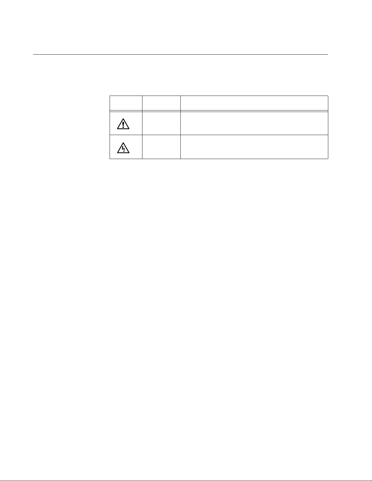
This document uses the safety symbols defined in Table 1.
Table 1. Safety Symbols
Symbol Meaning Description
Caution Performing or omitting a specific action may
result in equipment damage or loss of data.
Warning Performing or omitting a specific action may
result in electrical shock.
12
Page 13

Where to Find Web-based Guides
The installation and user guides for all Allied Telesis products are available
in portable document format (PDF) on our web site at
www.alliedtelesis.com. You can view the documents online or download
them onto a local workstation or server.
AT-CV1203 Chassis Installation Guide
13
Page 14

Preface
Contacting Allied Telesis
This section provides Allied Telesis contact information for technical
support as well as sales and corporate information.
Online Support You can request technical support online by accessing the Allied Telesis
Knowledge Base: www.alliedtelesis.com/support/kb.aspx. You can use
the Knowledge Base to submit questions to our technical support staff and
review answers to previously asked questions.
Email and
Telephone
Support
Returning
Products
Sales or
Corporate
Information
Management
Software Updates
For Technical Support via email or telephone, refer to the Allied Telesis
web site at www.alliedtelesis.com. Select your country from the list on
the web site and then select the appropriate tab.
Products for return or repair must first be assigned a return materials
authorization (RMA) number. A product sent to Allied Telesis without an
RMA number will be returned to the sender at the sender’s expense. For
instructions on how to obtain an RMA number, go to the Support section
on our web site at www.alliedtelesis.com.
You can contact Allied Telesis for sales or corporate information through
our web site at www.alliedtelesis.com.
New releases of the management software for our managed products are
available from the following Internet sites:
Allied Telesis web site: www.alliedtelesis.com
Allied Telesis FTP server: ftp://ftp.alliedtelesis.com
If the FTP server prompts you to log on, enter “anonymous” as the user
name and your email address as the password.
14
Page 15

Chapter 1
Overview
This chapter contains the following sections:
“Features” on page 16
“Front and Back Panels” on page 17
“AT-CVMNT12 Wall-Mount Bracket” on page 18
“LEDs” on page 19
“Operations, Administration and Maintenance Features” on page 20
15
Page 16

Chapter 1: Overview
Features
The AT-CV1203 Chassis is part of the Converteon product line. It is a twoslot enclosure for the Fast and Gigabit Ethernet media converter line cards
and the AT-CV5M02 Management Card. The chassis is compatible with
all the Converteon line cards and can accommodate two line cards, one
line card and the AT-CV5M02 Management Card, or the dual-slot
AT-CM70S Media Converter Line Card.
You can place the chassis on a table or desk, or mount it on the wall with
the optional AT-CVMNT12 Wall-Mount Bracket.
The chassis comes with a single power adapter. A second power adapter
can be added for power redundancy.
You can use the chassis and the line cards as managed or unmanaged
devices. To add management, you can either install the AT-CV5M02
Management Card or use remote peer management, which is one of the
Operations, Administration, and Maintenance features and which lets you
manage remote line cards from their local counterparts in a managed
chassis.
16
Allied Telesis
AT-CV1203
C
L
A
L
A
S
S
E
R
S
P
1
R
O
D
U
C
2
T
1
1568
Figure 1. AT-CV1203 Chassis
Note
For the current list of the Converteon line cards, refer to the Allied
Telesis web site or contact your authorized sales representative.
Page 17

Front and Back Panels
Figure 2 shows the front and back panels of the AT-CV1203 Chassis.
Allied Telesis
AT-CV1203
1
SS
LA
C
T
C
U
OD
R
P
ER
S
LA
AT-CV1203 Chassis Installation Guide
Slot 2
2
2
1
1
1578
Slot 1
DC Power Connectors
(PWR A and PWR B)
PWR Good
LED
PWR GOOD
Grounding Lug
Screws
Tie Wrap
Anchors
Power Adapter
PWR A
PWR B
LEDs
12VDC
12VDC
1579
Figure 2. Front and Back Panels of the AT-CV1203 Chassis
17
Page 18

Chapter 1: Overview
AT-CVMNT12 Wall-Mount Bracket
The AT-CV1203 Chassis can be mounted on a wall with the optional
AT-CVMNT12 Wall-Mount Bracket, shown in Figure 3. To order the
bracket, contact your Allied Telesis sales representative.
1015
Figure 3. AT-CVMNT12 Wall-Mount Bracket
18
Page 19

LEDs
AT-CV1203 Chassis Installation Guide
Figure 4 identifies the power LEDs on the rear panel.
PWR Good LED
PWR GOOD
Power Adapter LEDs
12VDC
PWR A
12VDC
PWR B
1579
Figure 4. Power LEDs
Table 1 describes the power LEDs.
Table 1. Power LEDs
LED State Description
PWR GOOD Green The power being supplied to the line cards
is within the normal operating range.
OFF The chassis is not receiving power or the
power is outside the normal operating
range.
PWR A Green Power adapter A is operating normally.
OFF Power adapter A is not receiving power,
isn’t present, or has failed.
PWR B Green Power adapter B is operating normally.
OFF Power adapter B is not receiving power,
isn’t present, or has failed.
19
Page 20

Chapter 1: Overview
Operations, Administration and Maintenance Features
The AT-CV1203 Chassis supports all the Operations, Administration and
Maintenance (OAM) features of the managed AT-CM2 Series and
AT-CM3 Series Line Cards and the AT-CM70S Line Card. The features
are listed here and are fully described in the Converteon AT-S73, AT-S99,
and AT-S102 Management Software User’s Guide:
Remote peer management - This feature lets you configure remote
line cards in an unmanaged chassis through their line card
counterparts in a managed chassis.
Remote updates of the AT-S73 or AT-S102 Management Software -
This feature lets you download new management software to remote
AT-CM2 Series and AT-CM3 Series Line Cards from their local
counterparts.
OAM loopback tests - This feature lets you test the quality of the fiber
optic cable that connects two line cards or that connects a line card to
some other OAM-compliant device.
Dying gasp and first RPS failure signals - This feature notifies you if a
power supply on the AT-CV1203 Chassis loses power.
OAM variable requests - This feature lets you send queries for the
values of MIB objects on OAM-compliant devices.
If you plan to implement the dying gasp and the first RPS failure features,
note the following:
There are two versions of the AT-CV1203 Chassis. Units built after
March 2009 and having “04187” or “04188” in their serial numbers
support the first RPS failure signal on the AT-CM3 Series Media
Converter Line Cards without the AT-CV5M02 Management Module:
Serial Number: x04187xxxxxxxxxx
Serial Number: x04188xxxxxxxxxx
The dying gasp and first RPS failure signals will not work if the
AT-CV1203 Chassis contains both an AT-CM2 Series Line Card and
an AT-CM3 Series Line Card. If you plan to use these features, do not
install cards from both series in the same chassis.
20
Page 21

Chapter 2
Installation
This chapter contains the following installation procedures for the
AT-CV1203 Chassis:
“Reviewing the Safety Precautions” on page 22
“Selecting a Site for the Chassis” on page 23
“Unpacking the Chassis” on page 24
“Installing the Rubber Feet” on page 26
“Installing a Converteon Line Card” on page 27
“Grounding the Chassis” on page 30
“Powering On the Chassis” on page 32
“Verifying the Installation” on page 35
“Replacing a Line Card or the Management Card” on page 36
Note
For instructions on how to install the AT-CV1203 Chassis on a wall
with the AT-CVMNT12 Wall-Mount Bracket, refer to the installation
guide included with the bracket.
21
Page 22

Chapter 2: Installation
Reviewing the Safety Precautions
Please review the following safety precautions before you begin to install
the chassis or any of its components.
Note
The indicates that a translation of the safety statement is
available in a PDF document titled Translated Safety Statements on
the Allied Telesis website at www.alliedtelesis.com and on the
documentation CD shipped with this product.
Warning: Do not work on equipment or cables during periods of
lightning activity.
Warning: Power cord is used as a disconnection device. To deenergize equipment, disconnect the power cord.
E2
E3
Warning: Class I Equipment. This equipment must be earthed.
The power plug must be connected to a properly wired earth
ground socket outlet. An improperly wired socket outlet could
E4
E7
place hazardous voltages on accessible metal parts.
Pluggable Equipment. The socket outlet shall be installed near
E5
E6
the equipment and shall be easily accessible.
Caution: Air vents must not be blocked and must have free
access to the room ambient air for cooling.
Warning: Operating Temperature. This product is designed for a
maximum ambient temperature of 40° degrees C.
All Countries: Install product in accordance with local and
National Electrical Codes.
Warning: Remove all metal jewelry, such as rings and watches,
before installing or removing a line card from a powered-on
chassis.
E26
E8
22
Page 23

Selecting a Site for the Chassis
The site chosen for the unit should meet the following requirements:
The power outlet should be close to the chassis and be easily
accessible.
The site should allow for easy access to the media converter module
slots on the front panel and to the power supply connectors on the
back panel.
There should be unrestricted air flow around the vents of the chassis.
There should not be any objects placed on top of the chassis.
The site should be a moisture-free environment.
The site should be a dust-free environment.
The power sources for a chassis that has two power supplies should
be located on different circuits to protect the unit from a power circuit
failure.
AT-CV1203 Chassis Installation Guide
Dedicated power circuits or power conditioners should be used to
provide reliable electrical power to the network device.
If you are installing the chassis on a table, the table should be level
and secure.
The site should not expose the media converter chassis or the twisted
pair cables to sources of electrical noise, such as radios, electric
motors, transmitters, broadband amplifiers, power lines, and
fluorescent fixtures.
23
Page 24

Chapter 2: Installation
Unpacking the Chassis
As you unpack the unit, verify that all the items listed in Table 2 are
included in the shipping container. If an item is missing or damaged,
contact your Allied Telesis sales representative for assistance.
Note
Store the packaging material in a safe location. You must use the
original shipping material if you need to return the unit to Allied
Telesis.
Table 2. AT-CV1203 Chassis Components
Component Description
One AT-CV1203 Chassis
Allied Telesis
AT-CV1203
C
L
A
L
A
S
S
E
R
S
P
1
R
O
D
U
C
2
T
1
1568
One power adapter
1569
One AC power cord with regionspecific AC power connector
24
1570
Page 25

AT-CV1203 Chassis Installation Guide
Table 2. AT-CV1203 Chassis Components
Component Description
Two pre-installed AT-CV5PNL1
slot covers
AT-CV5PNL1
AT-CV5PNL1
1571
Four rubber feet
1437
One grounding lug
1409
Two tie wraps
1583
25
Page 26

Chapter 2: Installation
Installing the Rubber Feet
If you are installing the AT-CV1203 Chassis on a desktop, turn the unit
over and attach the four rubber feet to the corners, as shown in Figure 5.
1
T
2
1
PRODUC
LASER
CLASS
AT-CV1203
Allied Telesis
Figure 5. Attaching the Rubber Feet
1572
26
Page 27

Installing a Converteon Line Card
AT-CV5PNL1
AT-CV5PNL1
To install a Converteon media converter line card or the AT-CV5M02
Management Card in the chassis, perform the following procedure:
1. Using a Phillips-head screwdriver, loosen the captive screw on one of
the AT-CV5PNL1 blank slot covers and remove the cover. The cards
can be installed in either slot. If you are installing the AT-CM70S Line
Card, remove the covers from both slots.
Allied Telesis
AT-CV1203
LASER PRODUC
AT-CV1203 Chassis Installation Guide
CLASS
1
T
Allied Telesis
AT-CV1203
CLASS 1
LASER PRODUC
T
AT-CV5PNL1
Figure 6. Removing a Slot Cover
1573
27
Page 28

Chapter 2: Installation
Note
Empty slots should be kept covered. Retain the slot cover and
reinstall it if you ever remove the line card without replacing it.
2. Remove the Converteon media converter line card or the AT-CV5M02
Management Card from its shipping package.
Store the package in a safe place. You must use the original package
if you need to return the unit to Allied Telesis.
Caution
Be sure to observe all standard electrostatic discharge (ESD)
precautions, such as wearing an antistatic wrist strap, to avoid
damaging the device. Line cards can be damaged by static
electricity.
3. Set the line card’s DIP switches if necessary. For instructions, refer to
the documentation that ships with the line card.
4. Align the edges of the line card with the left and right alignment guides
located inside the slot.
Allied Telesis
AT-CV1203
2
2
CLASS 1
T
LASER PRODUC
1
1574
Alignment Guides
Figure 7. Alignment Guides
5. Slide the line card into the slot, as shown in Figure 8, until the front
panel of the line card is flush with the front of the chassis.
Caution
Do not force the line card into place. If there is resistance, remove
the card, verify that the edges of the card are properly aligned in the
guides in the chassis’ module slot, and reinsert it.
28
Page 29

Allied Telesis
AT-CV5PNL1
AT-CM302
LK AT
S
F
P
LK AT FD
SML ML OAM
T
X
RDY
100M
AT-CV5PNL1
AT-CM302
LK AT
S
F
P
LK AT FD
SML ML OAM
T
X
RDY
100M
AT-CV1203
CLASS
LASER PRODUCT
1
AT-CV1203 Chassis Installation Guide
1575
Figure 8. Inserting a Line Card
6. Use a Phillips screwdriver to tighten the captive screw on the line card,
as shown in Figure 9.
Allied Telesis
AT-CV1203
CLASS
LASER PRODUC
1
T
1576
Figure 9. Tightening the Captive Screw
7. To install another card in the chassis, repeat this procedure.
For instructions on how to cable the line cards or the management card,
refer to the documentation that ships with the units.
29
Page 30

Chapter 2: Installation
Grounding the Chassis
This procedure requires these items:
Phillips head No. 2 screwdriver
10 AWG solid wire (The length of the wire will depend on your
installation.)
Crimping tool
Grounding lug (included with the chassis)
To ground the AT-CV1203 Chassis, perform the following procedure:
1. Strip the grounding wire as shown in Figure 10.
11mm ±1mm
(0.44in. ±0.03in.)
100
Figure 10. Stripping the Grounding Wire
2. Use a crimping tool to attach the wire to the grounding lug included
with the chassis.
102
Figure 11. Attaching the Grounding Wire to the Grounding Lug
30
Page 31

AT-CV1203 Chassis Installation Guide
3. Remove the two grounding lug screws from the back panel of the
chassis.
PW
R
G
O
O
D
PW
R A
12VDC
PWR B
12VDC
1580
Figure 12. Removing the Grounding Lug Screws
4. Attach the grounding lug to the back panel of the chassis using the two
screws removed in the previous step.
PW
R
G
O
O
D
PW
R A
12VDC
PWR B
12VDC
1581
Figure 13. Attaching the Grounding Lug
5. Attach the other end of the grounding wire to an appropriate grounding
point at your site.
31
Page 32

Chapter 2: Installation
Powering On the Chassis
Note
Use only power sources that are UL Listed (QQGQ or EPBU), TUV
Licensed or other Safety Agencies approved, and that are suitable
for country of use.
To power on the AT-CV1203 Chassis, perform the following procedure:
1. Connect the power cord to the power adapter, as shown in Figure 14.
1577
Figure 14. Connecting the Power Adapter and Power Cord
2. Plug the DC connector on the power adapter to either the PWR A or
PWR B connector on the back panel of the chassis.
32
Page 33

AT-CV1203 Chassis Installation Guide
PW
R
G
O
O
D
PW
R
A
12VDC
PW
R
B
12VDC
1582
Figure 15. Connecting the Power Cord
3. To prevent accidentally disconnecting the power cord from the
chassis, secure the cord to the tie anchor with a tie wrap.
P
W
R
G
O
O
D
PW
R
A
12VDC
PW
R
B
12VDC
1582
Figure 16. Securing the Power Cord with a Tie Wrap
33
Page 34

Chapter 2: Installation
4. Connect the power cord to an appropriate power source. For the
power requirements, refer to “Power Specifications” on page 37. The
chassis is now ready for network operations.
Warning: Power cord is used as a disconnection device. To de-
energize equipment, disconnect the power cord.
E3
Pluggable Equipment. The socket outlet shall be installed near
the equipment and shall be easily accessible.
E5
5. If you purchased a second power adapter, repeat this procedure to
install it.
Note
Connecting the two power supplies to different circuits will protect
the unit from a power circuit failure.
34
Page 35

Verifying the Installation
After powering on the chassis, view the PWR GOOD LED. The LED
should be ON. The PWR A and PWR B LEDs should also be ON for DC
connectors that are connected to power adapters. If an LED is OFF,
perform the following:
Verify that the power cord is firmly connected to the AC power source
and to the power adapter.
Verify that the power adapter is firmly connected to a DC connector on
the back panel of the chassis.
Verify that the power source is operating properly by plugging a
different device into it.
Try connecting the power adapter to another power source, preferably
located on a different circuit.
Try using a different power adapter and power cord.
Check that the voltage from the power source is within the required
levels for your region.
AT-CV1203 Chassis Installation Guide
For instructions on how to troubleshoot a problem with a line card, refer to
the documentation that ships with the card.
35
Page 36

Chapter 2: Installation
Replacing a Line Card or the Management Card
All the Converteon media converter line cards and the AT-CV5M02
Management Card support hot-swapping and can be installed while the
chassis is powered on.
To replace a line card, perform the following procedure:
1. Disconnect all the cables from the line card you want to remove from
the chassis.
2. Insert the dust cap into the fiber optic port on the line card.
3. Using a Phillips-head screwdriver, loosen the captive screw of the line
card.
4. Slide the line card from the chassis.
5. If you are replacing the line card, go to “Installing a Converteon Line
Card” on page 27.
6. If you are not replacing the line card, insert the AT-CV5PNL1 slot
cover in the slot and tighten the captive screw to secure it to the
chassis.
36
Page 37

Appendix A
Technical Specifications
Physical Specifications
Dimensions: 5.40 cm x 13.12 cm x 15.52 cm
Weight: 0.9 kg (1.98 lb)
Environmental Specifications
(2.12 in x 5.17 in x 6.11 in)
(H x W x L):
Operating Temperature: 0° C to 40° C (32° F to 104° F)
Storage Temperature: -25° C to 70° C (-13°F to 158° F)
Operating Humidity: 5% to 90% non-condensing
Storage Humidity: 5% to 95% non-condensing
Maximum Operating Altitude: 3,000 m (10,000 ft.)
Maximum Storage Altitude: 4,000 m (13,100 ft.)
Power Specifications
Power Adapter Output
Minimal Output: 9 VDC
Nominal Output: 12 VDC
Maximum Output: 15 VDC
Maximum Current: 3.3A @ 12 VDC
Output Connector: Coaxial Female Barrel
Inner Diameter: 2.5 mm
Outer Diameter: 5.5 mm
Power Adapter Input
Input Range: 100-240 AC @ 51-60 Hz
Input Connector: IEC320-C14 (3-Pole AC inlet)
37
Page 38

Appendix A: Technical Specifications
Safety and Electromagnetic Emissions Certifications
EMI: FCC Class A, EN55022 Class A,
VCCI Class A, C-TICK, CE
Immunity: EN55024
Safety: UL60950-1 (
CULUS
), EN60950-1 (TUV),
CAN/CSA C22.2 No. 60950-1
Laser: EN60825
Quality and Reliability: MTBF > 310,000 hrs. (Telcordia Standards)
38
 Loading...