

Page 1

CONVERTEON™ Family
One-Slot Chassis
AT-CV1000
Installation Guide
613-000810 Rev. A
Page 2

Copyright © 2007 Allied Telesis, Inc.
All rights reserved. No part of this publication may be reproduced without prior written permission from Allied Telesis, Inc.
Allied Telesis is a trademark of Allied Telesis, Inc. Microsoft and Internet Explorer are registered trademarks of Microsoft
Corporation. Netscape Navigator is a registered trademark of Netscape Communications Corporation. All other product names,
company names, logos or other designations mentioned herein are trademarks or registered trademarks of their respective
owners.
Allied Telesis, Inc. reserves the right to make changes in specifications and other information contained in this document without
prior written notice. The information provided herein is subject to change without notice. In no event shall Allied Telesis, Inc. be
liable for any incidental, special, indirect, or consequential damages whatsoever, including but not limited to lost profits, arising
out of or related to this manual or the information contained herein, even if Allied Telesis, Inc. has been advised of, known, or
should have known, the possibility of such damages.
Page 3

Electrical Safety and Emissions Standards
This product meets the following standards.
U.S. Federal Communications Commission
Radiated Energy
Note: This equipment has been tested and found to comply with the limits for a Class A digital device pursuant to Part 15
of FCC Rules. These limits are designed to provide reasonable protection against harmful interference when the
equipment is operated in a commercial environment. This equipment generates, uses, and can radiate radio frequency
energy and, if not installed and used in accordance with this instruction manual, may cause harmful interference to radio
communications. Operation of this equipment in a residential area is likely to cause harmful interference in which case
the user will be required to correct the interference at his own expense.
Note: Modifications or changes not expressly approved of by the manufacturer or the FCC, can void your right to operate
this equipment.
Industry Canada
This Class A digital apparatus complies with Canadian ICES-003.
Cet appareil numérique de la classe A est conforme à la norme NMB-003 du Canada.
European Union Restriction of the Use of Certain Hazardous Substances
(RoHS) in Electrical and Electronic Equipment
This Allied Telesis RoHS-compliant product conforms to the European Union Restriction of the Use of Certain Hazardous
Substances (RoHS) in Electrical and Electronic Equipment. Allied Telesis ensures RoHS conformance by requiring
supplier Declarations of Conformity, monitoring incoming materials, and maintaining manufacturing process controls.
RFI Emissions FCC Class A, EN55022 Class A, EN61000-3-2, EN61000-3-3, VCCI
Class A, C-TICK, CE
Warning: In a domestic environment this product may cause radio interference in
which case the user may be required to take adequate measures.
Immunity EN55024
Electrical Safety EN60950 (TUV), UL 60950 (
CULUS
)
Laser Safety EN60825
3
Page 4

Translated Safety Statements
Important: The indicates that a translation of the safety statement is available in a PDF
document titled “Translated Safety Statements” posted on the Allied Telesis website at
www.alliedtelesis.com and on the documentation CD shipped with this product.
4
Page 5

Contents
Preface ..................................................................................................................................................................................9
Safety Symbols Used in this Document................................................................................................................................10
Where to Find Web-based Guides .......................................................................................................................................11
Contacting Allied Telesis ......................................................................................................................................................12
Online Support ..............................................................................................................................................................12
Email and Telephone Support .......................................................................................................................................12
Warranty........................................................................................................................................................................12
Returning Products........................................................................................................................................................12
Sales or Corporate Information .....................................................................................................................................12
Management Software Updates ....................................................................................................................................12
Chapter 2: Overview ..........................................................................................................................................................13
Features ...............................................................................................................................................................................14
......................................................................................................................................................................................15
Converteon™ Line Cards .....................................................................................................................................................16
Blank Slot Cover...................................................................................................................................................................17
Power Adapter......................................................................................................................................................................18
Network Topologies..............................................................................................................................................................19
Standalone Topology ....................................................................................................................................................19
Back-to-Back Topology .................................................................................................................................................20
Chapter 3: Installation .......................................................................................................................................................21
Reviewing Safety Precautions..............................................................................................................................................22
Selecting a Site for the Chassis............................................................................................................................................23
Unpacking the Chassis.........................................................................................................................................................24
Using the AT-CV1000 Chassis on a Desktop.......................................................................................................................25
Mounting the AT-CV1000 Chassis on a Wall .......................................................................................
Installing an AT-CV1000 Chassis in an AT-MCR12 Rack-Mount Chassis ...........................................................................28
Calculating the Power Requirements ............................................................................................................................28
Installing the AT-CV1000 Chassis.................................................................................................................................28
Installing a Converteon™ Line Card.....................................................................................................................................32
Powering On an AT-CV1000 Chassis ..................................................................................................................................35
Installing a Blank Slot Cover.................................................................................................................................................37
Warranty Registration...........................................................................................................................................................39
Warranty Registration...........................................................................................................................................................40
Appendix A: Technical Specifications .............................................................................................................................41
Physical Specifications .........................................................................................................................................................41
Environmental Specifications................................................................................................................................................41
Power Specifications ............................................................................................................................................................41
Safety and Electromagnetic Emissions Certifications...........................................................................................................42
................................26
5
Page 6

Contents
6
Page 7

Figures
Figure 1. AT-CV1000 One-Slot Converteon™ Chassis...................................................................................................... 14
Figure 2. AT-CV1000 Chassis Front and Back Panels....................................................................................................... 15
Figure 3. AT-CV5PNL1 Blank Slot Cover ........................................................................................................................... 17
Figure 4. AC Power Adapter............................................................................................................................................... 18
Figure 5. Standalone Network Topology ............................................................................................................................ 19
Figure 6. Back-to-Back Network Topology ......................................................................................................................... 20
Figure 7. Attaching Rubber Feet ........................................................................................................................................ 25
Figure 8. Installing the Wall-Mount Brackets on the Chassis ............................................................................................. 26
Figure 9. Installing the Plastic Anchors and Screws Onto the Wall.................................................................................... 27
Figure 10. Positioning The AT-CV1000 Chassis Onto the Wall Screws............................................................................. 27
Figure 11. AT-CVMCR Installation Adapter........................................................................................................................ 28
Figure 12. Removing the Mounting Rail from a Slot in the AT-MCR12 Chassis ................................................................ 29
Figure 13. Installing the AT-CVMCR Adapter on the AT-CV1000 Chassis ........................................................................ 29
Figure 14. AT-CV1000 Chassis with AT-CVMCR Adapter Installed................................................................................... 30
Figure 15. Sliding the AT-CV1000 into the AT-MCR12 Chassis Slot ................................................................................. 30
Figure 16. Tightening the Captive Screw on the AT-CVMCR Adapter ............................................................................... 31
Figure 17. Location of the Alignment Guides...................................................................................................................... 33
Figure 18. Inserting a Line Card ......................................................................................................................................... 33
Figure 19. Tightening the Captive Screw............................................................................................................................ 34
Figure 20. Connecting the Power Adapter and Power Cord............................................................................................... 35
Figure 21. Inserting an AT-CV5PNL1 Blank Slot Cover ..................................................................................................... 37
Figure 22. Tightening the Captive Screw on an AT-CV5PNL1 Blank Slot Cover ............................................................... 38
7
Page 8

Figures
8
Page 9

Preface
This guide contains instructions on how to install an AT-CV1000 One-Slot
Converteon™ chassis. This preface contains the following sections:
“Safety Symbols Used in this Document” on page 10
“Where to Find Web-based Guides” on page 11
“Contacting Allied Telesis” on page 12
9
Page 10
Preface
Safety Symbols Used in this Document
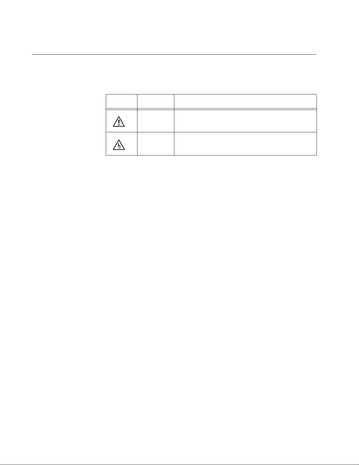
This document uses the safety symbols defined in Table 1.
Table 1. Safety Symbols
Symbol Meaning Description
Caution Performing or omitting a specific action may
result in equipment damage or loss of data.
Warning Performing or omitting a specific action may
result in electrical shock.
10
Page 11

Where to Find Web-based Guides
The installation and user guides for all Allied Telesis products are available
in portable document format (PDF) on our web site at
www.alliedtelesis.com. You can view the documents online or download
them onto a local workstation or server.
AT-CV1000 One-Slot Chassis Installation Guide
11
Page 12

Preface
Contacting Allied Telesis
This section provides Allied Telesis contact information for technical
support as well as sales and corporate information.
Online Support You can request technical support online by accessing the Allied Telesis
Knowledge Base: www.alliedtelesis.com/support/kb.aspx. You can use
the Knowledge Base to submit questions to our technical support staff and
review answers to previously asked questions.
Email and
Telephone
Support
For Technical Support via email or telephone, refer to the Support &
Services section of the Allied Telesis web site: www.alliedtelesis.com.
Select your country from the list displayed on the website. then select the
appropriate menu tab.
Warranty For hardware warranty information, refer to the Allied Telesis web site:
www.alliedtelesis.com/support/warranty.
Returning
Products
Sales or
Corporate
Products for return or repair must first be assigned a return materials
authorization (RMA) number. A product sent to Allied Telesis without an
RMA number will be returned to the sender at the sender’s expense.
To obtain an RMA number, contact the Allied Telesis Technical Support
group at our web site: www.alliedtelesis.com/support/rma. Select your
country from the list displayed on the website. Then select the appropriate
menu tab.
You can contact Allied Telesis for sales or corporate information through
our web site: www.alliedtelesis.com. To find the contact information for
your country, select Contact Us -> Worldwide Contacts.
Information
Management
Software Updates
12
New releases of management software for our managed products are
available from either of the following Internet sites:
Allied Telesis web site: www.alliedtelesis.com
Allied Telesis FTP server: ftp://ftp.alliedtelesis.com
If you prefer to download new software from the Allied Telesis FTP server
from your workstation’s command prompt, you will need FTP client
software and you must log in to the server. Enter “anonymous” for the user
name and your email address for the password.
Page 13

Chapter 2
Overview
This chapter contains the following sections:
“Features” on page 14
“Converteon™ Line Cards” on page 16
“Blank Slot Cover” on page 17
“Power Adapter” on page 18
“Network Topologies” on page 19
13
Page 14

Chapter 2: Overview
Features
The AT-CV1000 One-Slot Converteon™ chassis, as shown in Figure 1, is
designed to house any single Converteon™ line card.
AT-CV
1000
LASER PRODUC
CLASS 1
T
228
Figure 1. AT-CV1000 One-Slot Converteon™ Chassis
You can install the AT-CV1000 chassis on a desktop as a standalone
media converter, mount it on a wall, or install it in an AT-MCR12 chassis.
In addition, you can install the AT-CV1000 chassis in an AT-MCR12
media converstion rack-mount chassis. In order to do this, you must
purchase an AT-CVMCR Installation Adapter, available from Allied
Telesis.
The chassis has one pre-installed AT-CV5PNLx blank slot cover and an
AC power connector.
14
Page 15

AT-CV1000 One-Slot Chassis Installation Guide
Figure 2 shows the front and back panels of the AT-CV1000 chassis.
AT-CV1000
AT-CVPNLx Blank
Slot Cover
12VDC
AC Power
Connector
266
Figure 2. AT-CV1000 Chassis Front and Back Panels
15
Page 16

Chapter 2: Overview
Converteon™ Line Cards
The AT-CV1000 chassis can only house one Converteon™ line card. The
line card is hot swappable.
Note
For a current list of Converteon™ line cards, refer to the Allied
Telesis web site or consult your authorized sales representative. For
detailed descriptions of these line cards, refer to the documentation
shipped with the line cards and/or the Converteon™ Media
Converter Line Cards Reference Guide posted on our web site,
www.alliedtelesis.com.
16
Page 17

Blank Slot Cover
AT-CV1000 One-Slot Chassis Installation Guide
The AT-CV5PNL1 blank slot cover is designed to maintain optimal,
trouble-free environmental conditions for the AT-CV1000 chassis. An
unoccupied line card slot on the AT-CV1000 chassis should be covered
with a blank slot cover to keep dust from getting into the chassis and
maintain proper airflow, cooling, and ventilation throughout the chassis.
Figure 1 illustrates the AT-CV5PNL1 blank slot cover.
222
Figure 3. AT-CV5PNL1 Blank Slot Cover
Note
Allied Telesis strongly recommends that a blank slot cover be
inserted in any slot that does not contain a functioning line card.
To install a blank slot cover, refer to “Installing a Blank Slot Cover” on
page 37.
Note
Only the AT-CV5PNL1 of the AT-CV5PNLx blank cover series is
designed for the AT-CV1000 chassis. Be sure to ask for the
AT-CV5PNL1 if you need to order a new blank cover for this chassis.
17
Page 18

Chapter 2: Overview
Power Adapter
The AT-CV1000 chassis uses a two-part AC power adapter (supplied), as
shown in Figure 4.
517
Figure 4. AC Power Adapter
18
Page 19

Network Topologies
This section describes two network topologies you can create with the
Converteon™ Fast and Gigabit media converter line cards installe in an
AT-CV1000 chassis.
AT-CV1000 One-Slot Chassis Installation Guide
Standalone
Topology
Figure 5 illustrates a standalone topology using one AT-CV1000 chassis
with an AT-CM202 line card installed to interconnect two small networks.
Network 1 has an AT-FS709FC switch connected to the 100Base-FX
port on the AT-CM202 line card in the AT-CV1000 media converter.
Network 2 has an AT-8524M switch connected to the 10/100Base-TX
port on the AT-CM202 line card in the AT-CV1000 media converter.
NETWORK 1 NETWORK 2
AT-CV1000 (w/ AT-CM202)
T
XRX
M
AT-FS709FC
FS709FC
10BASE-T / 100BASE-TX 8 PORT FAST ETHERNET SWITCH WITH 100FX UPLINK
POWER
LINK/ACT
100M
FDX
1X 8MDI
123456789
2X 3X 4X 5X 6X 7X
LK AT
AT-CM202
M
F
X
AT-CV1000
AT-8524M
8MDI-X
9
OR
OAM
ATLK FD
10/
100
ML/
SML
T
X
RDY
AT-8524M
Twisted Pair
Fiber Optic
AT-8524M
Figure 5. Standalone Network Topology
AT-8524M
19
Page 20

Chapter 2: Overview
Back-to-Back
Topology
Figure 6 illustrates a back-to-back topology using two AT-CV1000
chassis, each with an AT-CM202 line card installed to interconnect two
small networks.
The media converters themselves are connected together through
100Base fiber optic ports on AT-CM202 line cards.
Network 1 has an AT-8350GB switch connected to the 10/100Base-TX
port on the AT-CM202 line card in the first AT-C1000 media converter.
Network 2 has an AT-8524M switch connected to the 10/100Base-TX
port on the AT-CM202 line card in the second AT-CV1000 media
converter.
NETWORK 1 NETWORK 2
AT-CV1000 (w/ AT-CM202)
T
XRX
M
AT-CV1000
LK AT
AT-CM202
M
F
X
OAM
ATLK FD
10/
100
ML/
SML
T
X
RDY
T
XRX
M
AT-CV1000
AT-CM202
M
LK AT
F
X
OAM
ATLK FD
10/
100
ML/
SML
T
X
RDY
1 1
1234567891011121314151617181920212223242526272829303132333435363738394041424344454647
LINK
RPS
PWR
100
FAULT
FULL
MODE
AT-8350GB
Twisted Pair
Fiber Optic
Figure 6. Back-to-Back Network Topology
S
49
M
S
50
M
48
AT-8524M
AT-8524M
AT-8524M
AT-8524M
20
Page 21

Chapter 3
Installation
This chapter contains the following installation procedures for the
AT-CV1000 chassis:
“Reviewing Safety Precautions” on page 22
“Selecting a Site for the Chassis” on page 23
“Unpacking the Chassis” on page 24
“Using the AT-CV1000 Chassis on a Desktop” on page 25
“Mounting the AT-CV1000 Chassis on a Wall” on page 26
“Installing an AT-CV1000 Chassis in an AT-MCR12 Rack-Mount
“Installing a Converteon™ Line Card” on page 32
Chassis” on page 28
“Powering On an AT-CV1000 Chassis” on page 35
“Installing a Blank Slot Cover” on page 37
“Warranty Registration” on page 39
21
Page 22

Chapter 3: Installation
Reviewing Safety Precautions
Please review the following safety precautions before you begin to install
the chassis or any of its components.
Note
The indicates that a translation of the safety statement is
available in a PDF document titled “Translated Safety Statements”
on the Allied Telesis website at www.alliedtelesis.com and on the
documentation CD shipped with this product.
Warning: Do not work on equipment or cables during periods of
lightning activity.
Warning: Power cord is used as a disconnection device. To deenergize equipment, disconnect the power cord.
E2
E3
Warning: Class I Equipment. This equipment must be earthed.
The power plug must be connected to a properly wired earth
ground socket outlet. An improperly wired socket outlet could
E4
E7
place hazardous voltages on accessible metal parts.
Pluggable Equipment. The socket outlet shall be installed near
E5
E6
the equipment and shall be easily accessible.
Caution: Air vents must not be blocked and must have free
access to the room ambient air for cooling.
Warning: Operating Temperature. This product is designed for a
maximum ambient temperature of 40° degrees C.
All Countries: Install product in accordance with local and
National Electrical Codes.
Caution: The attached mounting brackets must be used to
securely mount the device on the wall.
E8
E15
22
Warning: Remove all metal jewelry, such as rings and watches,
before installing or removing a line card from a powered-on
chassis.
E26
Page 23

Selecting a Site for the Chassis
Observe the following requirements when choosing a site for the chassis:
The power outlet for the chassis should be located near the unit and
should be easily accessible.
The site should provide easy access to the ports on the front and the
power supply on the back of the chassis. This arrangement will make it
easy for you to connect and disconnect cables as well as to view the
LEDs.
To allow proper cooling of the chassis, air flow around the unit and
through its vents should be unrestricted.
Do not place objects on top of the chassis.
Do not expose the chassis to moisture or water.
Make sure that the site is a dust-free environment.
AT-CV1000 One-Slot Chassis Installation Guide
23
Page 24

Chapter 3: Installation
Unpacking the Chassis
To unpack the chassis, perform the following procedure:
1. Remove all components from the shipping package.
2. Make sure that the following components are included in the package.
If any item is missing or damaged, contact your Allied Telesis sales
representative for assistance.
One AT-CV1000 chassis with an AT-CV5PNL1 blank slot cover
Note
Store the packaging material in a safe location. You must use the
original shipping material if you need to return the unit to Allied
Telesis.
installed
Four self-adhesive rubber feet
Two wall mounting brackets
Two plastic anchors (for wall mounting)
Two flat-head self-tapping screws (for wall mounting)
One power adapter
One power cord
Documentation CD
Warranty card
24
Page 25

Using the AT-CV1000 Chassis on a Desktop
To use the AT-CV1000 chassis on a desktop, perform the following
procedure:
1. Remove the chassis from the shipping container.
2. Turn the chassis over and place it on a secure surface.
3. Attach the four self-adhesive rubber feet, included, to the bottom of the
chassis, as shown in Figure 7.
AT-CV1000 One-Slot Chassis Installation Guide
262
AT-CV1000
Figure 7. Attaching Rubber Feet
4. Turn the chassis over again.
5. Install the line card according to the instructions in “Installing a
Converteon™ Line Card” on page 32.
6. Place the chassis in its intended location.
7. Cable the line card according to the instructions that were shipped with
the line card.
8. Power on the chassis according to the instructions in “Powering On an
AT-CV1000 Chassis” on page 35.
25
Page 26

Chapter 3: Installation
Mounting the AT-CV1000 Chassis on a Wall
The AT-CV1000 chassis is shipped with two wall-mounting brackets. The
chassis is designed to be mounted vertically on a wall using the keyholes
on the wall-mounted brackets.
To mount the AT-CV1000 chassis on a wall, perform the following
procedure:
1. If attached, remove the rubber feet, data cables, and power cord from
the chassis.
2. Install the line card according to the instructions in “Installing a
Converteon™ Line Card” on page 32.
3. Install the provided wall-mount brackets onto the chassis, as illustrated
in Figure 8.
AT-CM202
L
A
C
S
L
E
A
R
S
P
S
R
1
O
D
U
C
T
LK A
T
S
F
P
LK AT FD
T
X
SML ML OAM
Y
D
R
263
AT-CV1000
Figure 8. Installing the Wall-Mount Brackets on the Chassis
Caution: The attached mounting brackets must be used to
securely mount the device on the wall.
E15
4. Select a wall location for the device.
5. Place the chassis against the wall and mark the locations for the wall
anchors.
26
Page 27

AT-CV1000 One-Slot Chassis Installation Guide
6. Install two plastic anchors and two screws onto the wall, as illustrated
in Figure 9.
A
T-C
V
1
AT
0
0
-CM202
0
L
K
A
T
S
F
P
L
K
A
T
F
T
X
D
L
ASE
R
D
Y
SM
L
M
L
OA
M
R
P
C
RO
L
ASS
D
UC
1
T
295
Figure 9. Installing the Plastic Anchors and Screws Onto the Wall
7. Position the chassis vertically onto the wall screws, as illustrated in
Figure 10, and slide it down to secure the brackets against the wall.
40-60VDC INP
OAM
UT
SML ML
DY
R
2
0
2
0
00
1
V
C
T
A
LK AT FD
T
A
K
L
M
C
-
T
A
296
Figure 10. Positioning The AT-CV1000 Chassis Onto the Wall Screws
8. Cable the line card according to the instructions that were shipped with
the line card.
9. Power on the chassis according to the instructions in “Powering On an
AT-CV1000 Chassis” on page 35..
27
Page 28

Chapter 3: Installation
Installing an AT-CV1000 Chassis in an AT-MCR12 Rack-Mount Chassis
In order to install the AT-CV1000 chassis in an AT-MCR12 rack-mount
chassis, an AT-CVMCR Installation Adapter, as shown in Figure 11, is
required.
Note
For detailed descriptions and installation procedures for the
AT-MCR12 rack-mount chassis, refer to the AT-MCR12 Media
Conversion Rack-Mount Chassis Installation Guide available on the
Allied Telesis website, www.alliedtelesis.com.
Calculating the
Power
Requirements
293
Figure 11. AT-CVMCR Installation Adapter
Even if your AT-MCR12 rack-mount chassis contains two AT-PWR4
power supply modules (a primary and an auxiliary), the total available
power for the modules in the chassis is limited to 80 Watts. This limitation
determines how many media converters the AT-MCR12 chassis can
support before the primary power supply shuts down.
To avoid power problems, Allied Telesis strongly recommends that you
calculate the total power required to supply your chosen media converters
before you install them in the AT-MCR12 chassis. Use the following
approximate power consumption guidelines for your calculation:
Use 6 Watts of power for any MC series media converter and the
AT-CV1000 with any of the Converteon line cards except the
AT-CM2K 0 S.
Use 9 Watts of power for the AT-CV1000 with an AT-CM2K0S line
card installed.
If the total power requirement exceeds the 80 Watt limit, then multiple
AT-MCR12 rack-mount chassis are required.
28
Installing the
AT-CV1000
Chassis
To install an AT-CV1000 chassis in an AT-MCR12 rack-mount chassis
using the AT-CVMCR Installation Adapter, perform the following
procedure:
1. Choose the slot in the AT-MCR12 chassis where you want to install
Page 29

AT-CV1000 One-Slot Chassis Installation Guide
the AT-CV1000 chassis and loosen the captive screw to remove the
mounting rail from that slot, as shown in Figure 12.
MEDIA CONVERTER RACKMOUNT CHASSIS
MEDIA CONVERTER RACKMOUNT CHAASIS
MCR12
R A
W
P
B
R
PW
1251
Figure 12. Removing the Mounting Rail from a Slot in the AT-MCR12
Chassis
2. Turn the AT-CV1000 chassis upside down.
3. Turn the AT-CVMCR adapter over, align it with the base of the chassis,
and attach it to the chassis with two screws (provided), as shown in
Figure 13.
T
C
U
1
S
OD
S
R
A
P
L
C
R
E
S
A
L
1268
Figure 13. Installing the AT-CVMCR Adapter on the AT-CV1000 Chassis
29
Page 30

Chapter 3: Installation
T
X
R
DY
LK
AT FD
SML
M
L
O
A
M
4. Turn the chassis over, as shown Figure 14.
Y
RD
1266
Figure 14. AT-CV1000 Chassis with AT-CVMCR Adapter Installed
5. Use the thumb tab on the adapter to slide the AT-CV1000 chassis into
the AT-MCR12 chassis, as shown in Figure 15.
MEDIA CONVERTER RACKMOUNT CHASSIS
MEDIA CONVERTER RACKMO
MCR12
SIS
AA
NT CH
U
A
R
1252
PW
B
R
PW
AT-CM202
F
X
DY
R
T-CV1000
A
T
A
LK
AT FD
LK
T
X
M
A
O
L
M
SML
Figure 15. Sliding the AT-CV1000 into the AT-MCR12 Chassis Slot
6. Press gently on the AT-CV1000 chassis to seat the chassis into the
backplane.
30
Page 31

AT-CV1000 One-Slot Chassis Installation Guide
AT-CV1000
7. Tighten the captive screw on the AT-CVMCR adapter to secure the
AT-CV1000 in the chassis, as shown in Figure 16.
MEDIA CONVERTER RACKMOUNT CHASSIS
MEDIA CONVERTER RACKMOUNT CHAASIS
MCR12
AT-CM2 02
T
A
K
L
F
X
AT FD
LK
T
X
DY
R
M
A
O
ML
SML
PWR A
PWR B
1253
Figure 16. Tightening the Captive Screw on the AT-CVMCR Adapter
8. Install the line card according to the instructions in “Installing a
Converteon™ Line Card” on page 32.
31
Page 32

Chapter 3: Installation
Installing a Converteon™ Line Card
To install a Converteon™ line card, perform the following procedure:
Caution Be sure to observe all standard electrostatic discharge
(ESD) precautions, such as wearing an antistatic wrist strap, to
avoid damaging the device. A line card can be damaged by
static electricity.
1. Remove the Converteon™ line card from its shipping package and
store the package in a safe place.
Note
You must use the original package if you need to return the unit to
Allied Telesis.
2. Loosen the captive screw to remove the AT-CV5PNL1 blank slot cover
from the AT-CV1000.
Keep the blank slot cover in a safe area in case you remove the line
card. The blank slot cover is used to keep dust from getting into the
chassis and maintains proper airflow, cooling, and ventilation throughout the chassis.
3. Set the line card’s DIP switches.
For more information on the DIP switch settings, refer to the
Converteon™ Media Converter Line Cards Reference Guide.
32
Page 33

AT-CV1000 One-Slot Chassis Installation Guide
CLA
SS
1
LAS
ER
PRO
DUC
T
AT
-CV100
0
AT-CM202
LK A
T
LK
AT FD
SML
ML
OAM
R
D
Y
4. Locate the alignment guides on both sides of the slot, as shown in
Figure 17.
AT-CV1000
Alignment Guides
505
Figure 17. Location of the Alignment Guides
5. Align the back edge of the line card with the left and right alignment
guides located inside the slot.
6. Slide the line card into the slot, as shown in Figure 18, until the slot
cover is flush with the front of the chassis.
232
Figure 18. Inserting a Line Card
33
Page 34

Chapter 3: Installation
CLA
SS
1
LAS
ER
PRO
DUC
T
AT
-CV100
0
AT
-CM202
LK AT
LK
A
T FD
SML
ML OAM
R
D
Y
7. Use a Phillips screwdriver to tighten the captive screw on the line card,
as shown in Figure 19.
501
Figure 19. Tightening the Captive Screw
Note
Always tighten the captive screw to secure the line card to the
chassis.
Refer to the documentation shipped with your line card, or to the
Converteon™ Media Converter Line Cards Reference Guide for cabling
information.
34
Page 35

Powering On an AT-CV1000 Chassis
The AC power adapter for the AT-CV1000 chassis consists of two parts: a
power cord and a power adapter.
Note
The power adapter for the AT-CV1000 chassis is not used if the
chassis is installed in an AT-MCR12 rack-mount chassis.
Note
Use only power sources that are UL Listed (QQGQ or EPBU), TUV
Licensed or other Safety Agencies approved, and that are suitable
for country of use.
To power on an AT-CV1000 chassis, perform the following procedure:
AT-CV1000 One-Slot Chassis Installation Guide
1. Plug one end of the power cord into the socket on the power adapter,
plug the other end of the power cord into a power outlet, and plug the
pigtail cable on the power adapter into the power connector labeled
12VDC on the back of the converter, as shown in Figure 20.
12VDC
517
Plug In
Plug Together
Power Adapter
Plug into Wall Outlet
Figure 20. Connecting the Power Adapter and Power Cord
35
Page 36

Chapter 3: Installation
The chassis is now ready for network operations.
Warning: Power cord is used as a disconnection device. To de-
energize equipment, disconnect the power cord.
E3
Pluggable Equipment. The socket outlet shall be installed near
the equipment and shall be easily accessible.
E5
36
Page 37

Installing a Blank Slot Cover
CLA
SS
1
LAS
ER
PRO
DUC
T
AT
-CV100
0
The AT-CV1000 chassis is shipped with the line card slot covered with the
AT-CV5PNL1 blank slot cover. When the line card slot is unoccupied, you
should cover it with a blank slot cover, to keep dust from getting into the
chassis and to maintain proper airflow, cooling, and ventilation throughout
the chassis.
Note
Allied Telesis strongly recommends that a blank slot cover be
inserted in the AT-CV1000 chassis when it does not contain a
functioning line card.
To install an AT-CV5PNL1 blank slot cover, perform the following
procedure:
1. Disconnect the cables from all the ports on the line card you are
removing from the chassis.
AT-CV1000 One-Slot Chassis Installation Guide
2. Cover the fiber optic port with the dust cap.
3. Remove the line card from the slot.
4. Align the back edge of the AT-CV5PNL1 blank slot cover with the left
and right alignment guides.
5. Slide the blank slot cover into the slot, as shown in Figure 21, until the
slot cover is flush with the front of the chassis.
513
Figure 21. Inserting an AT-CV5PNL1 Blank Slot Cover
37
Page 38

Chapter 3: Installation
CLA
SS
1
LAS
ER
PRO
DUC
T
AT
-C
V
100
0
6. Use a Phillips screwdriver to tighten the captive screw, as shown in
Figure 22.
506
Figure 22. Tightening the Captive Screw on an AT-CV5PNL1 Blank Slot
Cover
Note
Always tighten the captive screw to secure the blank slot cover to
the chassis.
38
Page 39

Warranty Registration
AT-CV1000 One-Slot Chassis Installation Guide
39
Page 40

Chapter 3: Installation
Warranty Registration
Allied Telesis hardware products are covered under limited warranties.
Some products have a longer warranty coverage than others.
The AT-CV1000 chassis has a limited warranty of Lifetime (24 months
Fan & PSU).
All Allied Telesis warranties are subject to the terms and conditions set out
on the Allied Telesis website at www.alliedtelesis.com/warranty.
40
Page 41

Appendix A
Technical Specifications
Physical Specifications
Dimensions: W x D x H
Environmental Specifications
Operating Temperature: 0° C to 40° C (32° F to 104° F)
10.48 cm x 17.77 cm x 2.54 cm
(4.125 in x 7.0 in x 1.0 in)
Storage Temperature: -25° C to 70° C (-13°F to 158° F)
Operating Humidity: 5% to 90% non-condensing
Storage Humidity: 5% to 95% non-condensing
Maximum Operating Altitude: 3,000 m (10,000 ft.)
Maximum Storage Altitude: 4,000 m (13,100 ft.)
Power Specifications
Nominal Input: 12VDC
Input Current: 1.06A @ 12VDC
41
Page 42

Appendix A: Technical Specifications
Safety and Electromagnetic Emissions Certifications
EMI: FCC Class A, EN55022 Class A,
VCCI Class A, C-TICK, CE
Immunity: EN55024
Safety: UL60950-1 (
CULUS
), EN60950-1 (TUV),
CAN/CSA C22.2 No. 60950-1
Laser: EN60825
Quality and Reliability: MTBF > 100,000 hrs.
42
 Loading...