

Page 1

CONVERTEON™ Family
Media Converter Line Cards
AT-CM20x Series
AT-CM212x/1 Series
AT-CM2K0S
AT-CV10x Series
AT-CV1KSS
AT-CM70S
Reference Guide
613-50581-00 Rev. D
Page 2

Copyright 2006 Allied Telesis, Inc.
All rights reserved. No part of this publication may be reproduced without prior written permission from Allied Telesis, Inc.
Microsoft and Internet Explorer are registered trademarks of Microsoft Corporation. Netscape Navigator is a registered trademark of
Netscape Communications Corporation. All other product names, company names, logos or other designations mentioned herein are
trademarks or registered trademarks of their respective owners.
Allied Telesis, Inc. reserves the right to make changes in specifications and other information contained in this document without prior
written notice. The information provided herein is subject to change without notice. In no event shall Allied Telesis, Inc. be liable for any
incidental, special, indirect, or consequential damages whatsoever, including but not limited to lost profits, arising out of or related to this
manual or the information contained herein, even if Allied Telesis, Inc. has been advised of, known, or should have known, the possibility of
such damages.
Page 3

Electrical Safety and Emissions Standards
Standards: This product meets the following standards when installed in compliant host equipment.
U.S. Federal Communications Commission
Radiated Energy
Note: This equipment has been tested and found to comply with the limits for a Class A digital device pursuant to Part 15
of FCC Rules. These limits are designed to provide reasonable protection against harmful interference when the
equipment is operated in a commercial environment. This equipment generates, uses, and can radiate radio frequency
energy and, if not installed and used in accordance with this instruction manual, may cause harmful interference to radio
communications. Operation of this equipment in a residential area is likely to cause harmful interference in which case
the user will be required to correct the interference at his own expense.
Note: Modifications or changes not expressly approved of by the manufacturer or the FCC, can void your right to operate
this equipment.
Industry Canada
This Class A digital apparatus meets all requirements of the Canadian Interference-Causing Equipment Regulations.
Cet appareil numérique de la classe A respecte toutes les exigences du Règlement sur le matériel brouilleur du Canada.
RFI Emissions FCC Class A, EN55022 Class A, VCCI Class A, C-TICK, CE
Immunity EN55024
Electrical Safety EN60950-1 (TUV), UL 60950-1 (
Laser Safety EN60825
), CAN/CSA C22.2 No. 60950-1
CULUS
3
Page 4

Electrical Safety and Emissions Standards
Translated Safety Statements
Important: Appendix C contains translated safety statements for installing this equipment. When
you see the , go to Appendix C for the translated safety statement in your language.
Wichtig: Anhang C enthält übersetzte Sicherheitshinweise für die Installation dieses Geräts. Wenn
Sie sehen, schlagen Sie in Anhang C den übersetzten Sicherheitshinweis in Ihrer Sprache nach.
Importante: El Apéndice C contiene mensajes de seguridad traducidos para la instalación de este
equipo. Cuando vea el símbolo , vaya al Apéndice C para ver el mensaje de seguridad traducido
a su idioma.
Important : L'annexe C contient les instructions de sécurité relatives à l'installation de cet
équipement. Lorsque vous voyez le symbole , reportez-vous à l'annexe C pour consulter la
traduction de ces instructions dans votre langue.
Importante: l’Appendice C contiene avvisi di sicurezza tradotti per l’installazione di questa
apparecchiatura. Il simbolo , indica di consultare l’Appendice C per l’avviso di sicurezza nella
propria lingua.
Важно: Приложение C содержит переведенную инструкцию по безопасности при установке
данного устройства. Если Вы встретите , перейдите к Приложению C для получения
переведенной инструкции по безопасности.
4
Page 5

Contents
Electrical Safety and Emissions Standards ..................................................................................................................... 3
Figures................................................................................................................................................................................. 8
Tables ................................................................................................................................................................................ 10
Preface ............................................................................................................................................................................... 11
How This Guide is Organized.............................................................................................................................................. 11
Document Conventions ....................................................................................................................................................... 12
Where to Find Web-based Guides ...................................................................................................................................... 13
Contacting Allied Telesis ..................................................................................................................................................... 14
Online Support ............................................................................................................................................................. 14
Email and Telephone Support...................................................................................................................................... 14
Returning Products....................................................................................................................................................... 14
For Sales or Corporate Information.............................................................................................................................. 14
Obtaining Management Software Updates.......................................................................................................................... 15
Chapter 1: Converteon™ Fast Ethernet and Gigabit Ethernet Line Cards ................................................................. 16
Overview.............................................................................................................................................................................. 17
Line Card Descriptions ........................................................................................................................................................ 19
AT-CM20x Series ......................................................................................................................................................... 19
AT-CM212x/1 Series .................................................................................................................................................... 20
AT-CM2K0S ................................................................................................................................................................. 21
AT-CV10x Series.......................................................................................................................................................... 22
AT-CV1KSS ................................................................................................................................................................. 24
AT-CM70S.................................................................................................................................................................... 25
Hardware Features.............................................................................................................................................................. 26
100Base-FX Fiber Optic Ports............................................................................................................................................. 27
Type of Connector........................................................................................................................................................ 27
Speed ........................................................................................................................................................................... 27
Duplex Mode ................................................................................................................................................................ 27
Maximum Distance....................................................................................................................................................... 27
Type of Cable ............................................................................................................................................................... 28
10/100Base-TX Twisted Pair Ports...................................................................................................................................... 29
Type of Connector........................................................................................................................................................ 29
Speed ........................................................................................................................................................................... 29
Duplex Mode ................................................................................................................................................................ 29
Maximum Distance....................................................................................................................................................... 29
Type of Cable ............................................................................................................................................................... 29
Auto MDI/MDI-X ........................................................................................................................................................... 30
Port Pinouts.................................................................................................................................................................. 30
10/100/1000Base-T Twisted Pair Ports............................................................................................................................... 31
Type of Connector........................................................................................................................................................ 31
Speed ........................................................................................................................................................................... 31
Duplex Mode ................................................................................................................................................................ 31
Maximum Distance....................................................................................................................................................... 31
Type of Cable ............................................................................................................................................................... 31
Auto-MDI/
MDI-X .................................................................................................................................................................................. 31
Port Pinouts.................................................................................................................................................................. 32
5
Page 6

Contents
T1/E1 Port (AT-CM70S Line Cards Only)............................................................................................................................33
Type of Connector ........................................................................................................................................................33
Speed ........................................................................................................................................................................... 33
Type of Cable ...............................................................................................................................................................33
RS-232 Console Port (AT-CM70S Line Card Only).............................................................................................................34
Type of Connector ........................................................................................................................................................34
Specifications ............................................................................................................................................................... 34
Type of Cable ...............................................................................................................................................................34
SFP Expansion Slots ........................................................................................................................................................... 35
SFP Transceivers Supported by AT-CV1KSS and AT-CM2K0S Line Cards ............................................................... 35
Line Card and Port Status LEDs.......................................................................................................................................... 36
Line Card Status LEDs .................................................................................................................................................36
Fiber Optic Port LEDs...................................................................................................................................................38
Twisted Pair Port LEDs.................................................................................................................................................39
T1/E1 Port LEDs...........................................................................................................................................................41
Serial Port LEDs ...........................................................................................................................................................42
SFP Transceiver LEDs .................................................................................................................................................43
DIP Switches .......................................................................................................................................................................44
Link Test ....................................................................................................................................................................... 44
MissingLink™ ...............................................................................................................................................................44
Smart MissingLink ........................................................................................................................................................45
OAM Overview ............................................................................................................................................................. 45
AT-CM20x Series and AT-CM212x/1 Series Line Cards.............................................................................................. 50
AT-CV10x Series Line Cards........................................................................................................................................52
AT-CM2K0S Line Card................................................................................................................................................. 53
AT-CV1KSS Line Card .................................................................................................................................................54
AT-CM70S Line Card ................................................................................................................................................... 55
FCC Part 68 Customer Information..............................................................................................................................55
CPU RESET Button (AT-CM70S Line Card Only)...............................................................................................................56
Blank Slot Covers ................................................................................................................................................................57
A Few Basics about Media Converters................................................................................................................................58
MAC Address Table .....................................................................................................................................................58
Duplex Mode ................................................................................................................................................................59
Store-and-Forward ....................................................................................................................................................... 59
Network Topologies .............................................................................................................................................................60
Stand-Alone Topology ..................................................................................................................................................60
Back-to-Back Topology ................................................................................................................................................61
Chapter 2: Installation ...................................................................................................................................................... 62
Reviewing Safety Precautions .............................................................................................................................................63
Unpacking a Converteon™ Line Card .................................................................................................................................65
Installing a Converteon™ Line Card into a Converteon™ Chassis ..................................................................................... 66
Installing an SFP Transceiver in a Line Card.......................................................................................................................70
Cabling a Converteon™ Line Card ......................................................................................................................................71
Cabling a Fiber Optic Port ............................................................................................................................................71
Cabling a Twisted Pair Port .......................................................................................................................................... 75
Cabling an SFP Transceiver.........................................................................................................................................76
Cabling a RS-232 Console Port (AT-CM70S Line Card Only) .....................................................................................78
Resetting the AT-CM70S Line Card ....................................................................................................................................79
Installing a Line Card Blank Slot Cover ...............................................................................................................................80
Installing an AT-CV5PNL1 Blank Slot Cover................................................................................................................80
Warranty Registration..........................................................................................................................................................82
Chapter 3: Troubleshooting .............................................................................................................................................83
Converteon™ Line Cards .................................................................................................................................................... 83
RDY LED is OFF ..........................................................................................................................................................83
RDY LED is Flashing....................................................................................................................................................83
LK LED is OFF ............................................................................................................................................................. 84
LK LED is Flashing .......................................................................................................................................................84
6
Page 7

Converteon Media Converter Line Cards Reference Guide
Appendix A: Technical Specifications ............................................................................................................................ 85
Physical Specifications ........................................................................................................................................................ 85
Environmental Specifications............................................................................................................................................... 85
Electrical Specifications....................................................................................................................................................... 86
Optical Specifications .......................................................................................................................................................... 87
Safety and Electromagnetic Emissions Certifications.......................................................................................................... 88
RJ-45 Twisted Pair Port Pinouts.......................................................................................................................................... 89
RJ-48 T1/E1 Port Pinouts.................................................................................................................................................... 91
RS-232 Terminal Port Pinouts............................................................................................................................................. 92
8-Pin Mini-DIN Console Port Pinouts................................................................................................................................... 93
9-Pin Mini-DIN Serial Port Pinouts....................................................................................................................................... 94
SC Type Connectors ........................................................................................................................................................... 95
Dual SC Connector ...................................................................................................................................................... 95
Simplex SC Connector ................................................................................................................................................. 95
Dual ST Type Connector Cable........................................................................................................................................... 96
Dual ST Connector Cable ............................................................................................................................................ 96
SFP Transceiver.................................................................................................................................................................. 97
Link Test, MissingLink™, and Smart MissingLink LED Functionalities ............................................................................... 98
In Stand-Alone Topology.............................................................................................................................................. 98
In Back-to-Back Topology .......................................................................................................................................... 102
Appendix B: Cleaning Fiber Optic Connectors ........................................................................................................... 106
Using a Cartridge-Type Cleaner........................................................................................................................................ 107
Using a Swab .................................................................................................................................................................... 109
Appendix C: Translated Safety Statements ................................................................................................................. 111
7
Page 8

Figures
Figure 1. AT-CM202 Line Card.......................................................................................................................................... 19
Figure 2. AT-CM212A/1 Line Card .................................................................................................................................... 20
Figure 3. AT-CM2K0S Line Card....................................................................................................................................... 21
Figure 4. Sample of an AT-CV10x Series Line Card......................................................................................................... 22
Figure 5. AT-CV1KSS Line Card....................................................................................................................................... 24
Figure 6. AT-CM70S Line Card ......................................................................................................................................... 25
Figure 7. SFP Transceiver Module.................................................................................................................................... 35
Figure 8. DIP Switches on an AT-CM20x Series Line Card (AT-CM202) ......................................................................... 50
Figure 9. DIP Switches on an AT-CM212x/1 Series Line Card ......................................................................................... 50
Figure 10. DIP Switches on an AT-CM20x Series Line Card ............................................................................................ 52
Figure 11. DIP Switch on an AT-CM2K0S Line Card........................................................................................................ 53
Figure 12. DIP Switches on an AT-CV1KSS Line Card..................................................................................................... 54
Figure 13. Diagnostic Mode DIP Switch on an AT-CM70S Line Card............................................................................... 55
Figure 14. AT-CV5PNL1 Blank Slot Cover........................................................................................................................ 57
Figure 15. Stand-Alone Network Topology........................................................................................................................ 60
Figure 16. Back-to-Back Network Topology ...................................................................................................................... 61
Figure 17. AT-CV5000 Chassis Alignment Guide Locations............................................................................................. 67
Figure 18. AT-CV1000 Chassis Alignment Guide Locations............................................................................................. 67
Figure 19. AT-CV1200 Chassis Alignment Guide Locations............................................................................................. 67
Figure 20. Inserting the Line Card in an AT-CV5000 Chassis........................................................................................... 68
Figure 21. Inserting the Line Card in an AT-CV1000 Chassis........................................................................................... 68
Figure 22. Inserting the Line Card in an AT-1200 Chassis................................................................................................ 68
Figure 23. Tightening the Captive Screw........................................................................................................................... 69
Figure 24. Installing an SFP Transceiver in a Line Card................................................................................................... 70
Figure 25. Dual ST and SC Port........................................................................................................................................ 71
Figure 26. Removing the Dust Cover from a Dual SC Fiber Optic Port............................................................................. 72
Figure 27. Connecting to the Dual SC Fiber Optic Port..................................................................................................... 72
Figure 28. Connecting to the Dual SC Fiber Optic Port..................................................................................................... 73
Figure 29. Removing the Dust Cover from a Simplex SC Fiber Optic Port ....................................................................... 74
Figure 30. Connecting to the Simplex SC Fiber Optic Port ............................................................................................... 74
Figure 31. Connecting to the Twisted Pair Port ................................................................................................................. 75
Figure 32. Inserting an SFP Transceiver into the SFP Slot............................................................................................... 76
Figure 33. Removing the Dust Cover from the SFP Transceiver ...................................................................................... 76
Figure 34. Connecting Fiber Optic Cables to the SFP Transceiver................................................................................... 77
Figure 35. Connecting a Management Cable to the Console Port on an AT-CM70S Line Card....................................... 78
Figure 36. Resetting the CPU on the AT-CM70S Line Card ............................................................................................. 79
Figure 37. Inserting an AT-CV5PNL1 Blank Slot Cover .................................................................................................... 81
Figure 38. Tightening the Captive Screw on an AT-CV5PNL1.......................................................................................... 81
Figure 39. RJ-45 Connector and Port Pin Layout.............................................................................................................. 89
Figure 40. RJ-48 Connector and Port Pin Layout.............................................................................................................. 91
Figure 41. RS-232 Terminal Port Pinouts.......................................................................................................................... 92
Figure 42. 8-Pin Mini-DIN Console Port and Connector Pin Layouts ................................................................................ 93
Figure 43. 9-Pin Mini-DIN Serial Port and Connector Pin Layouts .................................................................................... 94
Figure 44. Dual SC Connector Cable ................................................................................................................................ 95
Figure 45. Simplex SC Connector Cable........................................................................................................................... 95
Figure 46. Dual ST Connector Cable................................................................................................................................. 96
Figure 47. SFP Transceiver............................................................................................................................................... 97
Figure 48. SFP Transceiver Cable .................................................................................................................................... 97
Figure 49. Converteon™ Module Configured in a Stand-Alone Topology......................................................................... 98
Figure 50. Converteon™ Module Configured in a Back-to-Back Topology ..................................................................... 102
8
Page 9

Converteon Media Converter Line Cards Reference Guide
Figure 51. Ferrule in an SC Connector Plug.................................................................................................................... 106
Figure 52. Unclean and Clean Ferrule............................................................................................................................. 106
Figure 53. Cartridge Cleaner ........................................................................................................................................... 107
Figure 54. Rubbing the Ferrule Tip on the Cleaning Surface .......................................................................................... 107
Figure 55. Lint-Free and Alcohol-Free Swabs................................................................................................................. 109
Figure 56. Cleaning a Recessed Ferrule......................................................................................................................... 109
9
Page 10

Tables
Table 1. Basic Line Card Configurations ........................................................................................................................... 17
Table 2. Line Card Status LEDs ........................................................................................................................................ 36
Table 3. AT-CM70S Line Card Status LEDs ..................................................................................................................... 37
Table 4. Line Card Fiber Optic Port LEDs ......................................................................................................................... 38
Table 5. AT-CM70S - Fiber Optic Port LEDs ..................................................................................................................... 38
Table 6. Line Card Twisted Pair Port LEDs ....................................................................................................................... 39
Table 7. AT-CM70S - Twisted Pair Port LEDs ................................................................................................................... 39
Table 8. T1/E1 Port LEDs .................................................................................................................................................. 41
Table 9. SFP Transceiver LEDs ........................................................................................................................................ 43
Table 10. AT-CM70S - SFP Transceiver LEDs ................................................................................................................. 43
Table 11. OAM Active and Passive Mode Behaviors ........................................................................................................ 49
Table 12. AT-CM20x Series and AT-CM212x/1 Series – Diagnostic Mode DIP Switch 1 Positions ................................. 50
Table 13. AT-CM20x Series and AT-CM212x/1 Series – Port Configuration DIP Switch 2 Positions ............................... 51
Table 14. AT-CV10x Series – Diagnostic Mode DIP Switch 1 Positions ........................................................................... 52
Table 15. AT-CV10x Series – Port Configuration DIP Switch 2 Positions ......................................................................... 52
Table 16. AT-CM2K0S – Diagnostic Mode DIP Switch Positions ...................................................................................... 53
Table 17. AT-CV1KSS – Diagnostic Mode DIP Switch Positions ...................................................................................... 54
Table 18. AT-CM70S Series – Diagnostic Mode DIP Switch Positions ............................................................................. 55
Table 19. Fiber Optic Cabling Specifications ..................................................................................................................... 87
Table 20. MDI Pin Signals (10/100Base-TX) ..................................................................................................................... 89
Table 21. MDI-X Pin Signals (10/100Base-TX) ................................................................................................................. 89
Table 22. MDI and MDI-X Pin Signals (1000Base-T) ........................................................................................................ 90
Table 23. RJ-48 Pin Signals .............................................................................................................................................. 91
Table 24. RS-232 Terminal Port Pin Signals ..................................................................................................................... 92
Table 25. 8-Pin Mini-DIN Console Port Pinouts ................................................................................................................. 93
Table 26. 8-Pin Mini-DIN Console Port Pinouts ................................................................................................................. 94
Table 27. Stand-Alone – Converteon™ Module in Link Test Mode ................................................................................... 99
Table 28. Stand-Alone – Converteon™ Module in MissingLink™ Test Mode ................................................................. 100
Table 29. Stand-Alone – Converteon™ Module in Smart MissingLink Test Mode .......................................................... 101
Table 30. Back-to-Back – Converteon™ Module in Link Test Mode ............................................................................... 103
Table 31. Back-to-Back – Converteon™ Module in MissingLink™ Test Mode ............................................................... 104
Table 32. Back-to-Back – Converteon™ Module in Smart MissingLink Test Mode ........................................................ 105
10
Page 11

Preface
This guide contains instructions on how to install and configure the
Converteon™ Series line cards in an AT-CV5000 Media Converter.
How This Guide is Organized
This guide contains the following chapters and appendices:
Chapter 1, ”Converteon™ Fast Ethernet and Gigabit Ethernet Line
Cards” on page 16
Chapter 2, ”Installation” on page 62
Chapter 3, ”Troubleshooting” on page 83
Appendix A, ”Technical Specifications” on page 85
Appendix B, ”Cleaning Fiber Optic Connectors” on page 106
Appendix C, ”Translated Safety Statements” on page 111
This preface contains the following sections:
“Document Conventions” on page 12
“Where to Find Web-based Guides” on page 13
“Contacting Allied Telesis” on page 14
“Obtaining Management Software Updates” on page 15
11
Page 12

Preface
Document Conventions
This document uses the following conventions:
Note
Notes provide additional information.
Caution
Cautions inform you that performing or omitting a specific action
may result in equipment damage or loss of data.
Warning
Warnings inform you that performing or omitting a specific action
may result in bodily injury.
12
Page 13

Where to Find Web-based Guides
The installation and user guides for all Allied Telesis products are available
in portable document format (PDF) from the Allied Telesis web site at
www.alliedtelesis.com. You can view the documents online or download
them onto a local workstation or server.
Refer to following manuals for instructions on how to install one of the
Converteon™ chassis or for description of the MissingLink™ and Smart
MissingLink features. The manuals come with the chassis and are also
available from the Allied Telesis web site:
AT-CV5000 Media Converter Chassis Installation Guide
PN 613-50580-00
AT-CV1000 Media Converter Chassis Installation Guide
PN 613-50582-00
AT-CV1200 Media Converter Chassis Installation Guide
PN 613-50583-00
Converteon Media Converter Line Cards Reference Guide
AT-S70 Management Software User’s Guide
PN 613-50485-00
13
Page 14

Preface
Contacting Allied Telesis
This section provides Allied Telesis contact information for technical
support as well as sales or corporate information.
Online Support You can request technical support online by accessing the Allied Telesis
Knowledge Base from the following web site:
http://www.alliedtelesis.com/support/kb.aspx. You can use the
Knowledge Base to submit questions to our technical support staff and
review answers to previously asked questions.
Email and
Telephone
Support
Returning
Products
For Sales or
Corporate
Information
For Technical Support via email or telephone, refer to the Allied Telesis
web site: http://www.alliedtelesis.com. Select your country from the list
displayed on the website. Then select the appropriate menu tab.
Products for return or repair must first be assigned a Return Materials
Authorization (RMA) number. A product sent to Allied Telesis without a
RMA number will be returned to the sender at the sender’s expense.
To obtain a RMA number, contact Allied Telesis’ Technical Support at our
web site: http://www.alliedtelesis.com. Select your country from the list
displayed on the website. Then select the appropriate menu tab.
You can contact Allied Telesis for sales or corporate information at our
web site: http://www.alliedtelesis.com. Select your country from the list
displayed on the website. Then select the appropriate menu tab.
14
Page 15

Obtaining Management Software Updates
New releases of management software for our managed products are
available for download from either of the following Internet sites:
Allied Telesis web site: www.alliedtelesis.com
Allied Telesis FTP server: ftp://ftp.alliedtelesis.com
If you prefer to download new software from the Allied Telesis FTP server
using your workstation’s command prompt, you will need FTP client
software and you must log in to the server. Enter “anonymous” as the user
name and your email address for the password.
Converteon Media Converter Line Cards Reference Guide
15
Page 16

Chapter 1
Converteon™ Fast Ethernet and Gigabit Ethernet Line Cards
This chapter contains the following sections:
“Overview” on page 17
“Line Card Descriptions” on page 19
“Hardware Features” on page 26
“100Base-FX Fiber Optic Ports” on page 27
“10/100Base-TX Twisted Pair Ports” on page 29
“10/100/1000Base-T Twisted Pair Ports” on page 31
“T1/E1 Port (AT-CM70S Line Cards Only)” on page 33
“RS-232 Console Port (AT-CM70S Line Card Only)” on page 34
“SFP Expansion Slots” on page 35
“Line Card and Port Status LEDs” on page 36
“DIP Switches” on page 44
“CPU RESET Button (AT-CM70S Line Card Only)” on page 56
“Blank Slot Covers” on page 57
“A Few Basics about Media Converters” on page 58
“Network Topologies” on page 60
16
Page 17

Overview
Converteon Media Converter Line Cards Reference Guide
Table 1 lists the configurations of the line cards that are currently available
to be used with any Converteon™ Media Converter Chassis.
Table 1. Basic Line Card Configurations
Line Card
Type of
Port/Slot
Connector Cable Speed
AT-CM201 Fiber Optic Dual ST 50/125 or
62.5/125 micron
Multi-Mode
Copper RJ-45 Twisted-Pair 10 Mbps or
AT-CM202 Fiber Optic Dual SC 50/125 or
62.5/125 micron
Multi-Mode
1
Copper RJ-45 Twisted-Pair 10 Mbps or
AT-CM202/1 Fiber Optic Dual SC 9/125 micron
Single-Mode
Copper RJ-45 Twisted-Pair 10 Mbps or
AT-CM202/2 Fiber Optic Dual SC 9/125 micron
Single-Mode
Maximum
Distance
100 Mbps 2 kilometers
(1.24 miles)
1
100 meters
100 Mbps
(328 feet)
100 Mbps 2 kilometers
(1.24 miles)
100 meters
100 Mbps
(328 feet)
100 Mbps 15 kilometers
2
(9.4 miles)
100 meters
100 Mbps
(328 feet)
100 Mbps 40 kilometers
2
(24.8 miles)
Copper RJ-45 Twisted-Pair 10 Mbps or
AT-CM2K0S SFP Varies by SFP
transceiver
Copper RJ-45 Twisted-Pair 10 Mbps,
AT-CM212A/1
Fiber Optic Simplex SC 9/125 micron
AT-CM212B/1
Copper RJ-45 Twisted-pair 100 Mbps 100 meters
Varies by SFP
transceiver
Single-Mode
3
2
100 meters
100 Mbps
(328 feet)
1.25 Gbps Varies by SFP
transceiver
100 meters
100 Mbps, or
(328 feet)
1000 Mbps
100 Mbps 15 kilometers
(9.4 miles)
(328 feet)
17
Page 18

Chapter 1: Converteon™ Fast Ethernet and Gigabit Ethernet Line Cards
Table 1. Basic Line Card Configurations
Line Card
Type of
Port/Slot
Connector Cable Speed
AT-CV101 Fiber Optic Dual ST 50/125 or
62.5/125 micron
Multi-Mode
1
Copper RJ-45 Twisted-Pair 100 Mbps 100 meters
AT-CV102 Fiber Optic Dual SC 50/125 or
62.5/125 micron
Multi-Mode
Copper RJ-45 Twisted-pair 100 Mbps 100 meters
AT-CV102/1 Fiber Optic Dual SC 9/125 micron
Single-Mode
Copper RJ-45 Twisted-pair 100 Mbps 100 meters
AT-CV102/2 Fiber Optic Dual SC 9/125 micron
Single-Mode
Maximum
Distance
100 Mbps 2 kilometers
(1.24 miles)
(328 feet)
100 Mbps 2 kilometers
(1.24 miles)
1
(328 feet)
100 Mbps 40 kilometers
2
(24.8 miles)
(328 feet)
100 Mbps 15 kilometers
2
(9.4 miles)
Copper RJ-45 Twisted-pair 100 Mbps 100 meters
AT-CV1KSS SFP Varies by SFP
transceiver
SFP Varies by SFP
transceiver
AT-CM70S SFP Varies by SFP
transceiver
Copper RJ-45 Twisted-Pair 10 Mbps or
T1/E1 RJ-48 Twisted-Pair n/a n/a
RS-232
Mini-DIN RS-232 Serial n/a n/a
Console
1. Do not use single-mode fiber optic cable with these ports.
2. SFP transceiver sold separately.
Varies by SFP
transceiver
2
Varies by SFP
transceiver
3
Varies by SFP
transceiver
3
(328 feet)
1.25 Gbps Varies by SFP
transceiver
1.25 Gbps Varies by SFP
transceiver
1.25 Gbps Varies by SFP
transceiver
100 meters
100 Mbps
(328 feet)
18
Page 19
Converteon Media Converter Line Cards Reference Guide
Line Card Descriptions
AT-CM20x Series The AT-CM20x Series line cards are 10/100 Mbps copper-to-fiber media
converter line cards. These line cards can be installed in any of the
Converteon™ Media Converter chassis, including the AT-CV5000,
AT-CV1000, and AT-CV1200. Each line card features one fiber optic port
and one copper twisted pair port. The fiber optic port operates at a fixed
operating speed of 100 megabits per second (Mbps) and the twisted pair
port operates at 10 or 100 Mbps speed. The fiber optic port is IEEE
802.3ah-compliant and has either a dual ST or a dual SC connector with a
maximum operating distance from 2 kilometers (1.24 miles) to 40
kilometers (24.8 miles), depending on the model. The twisted pair port has
an RJ-45 connector and a maximum operating distance of 100 meters
(328 feet). Both ports feature half- or full-duplex mode operation. The line
card is hot-swappable into and out of the chassis.
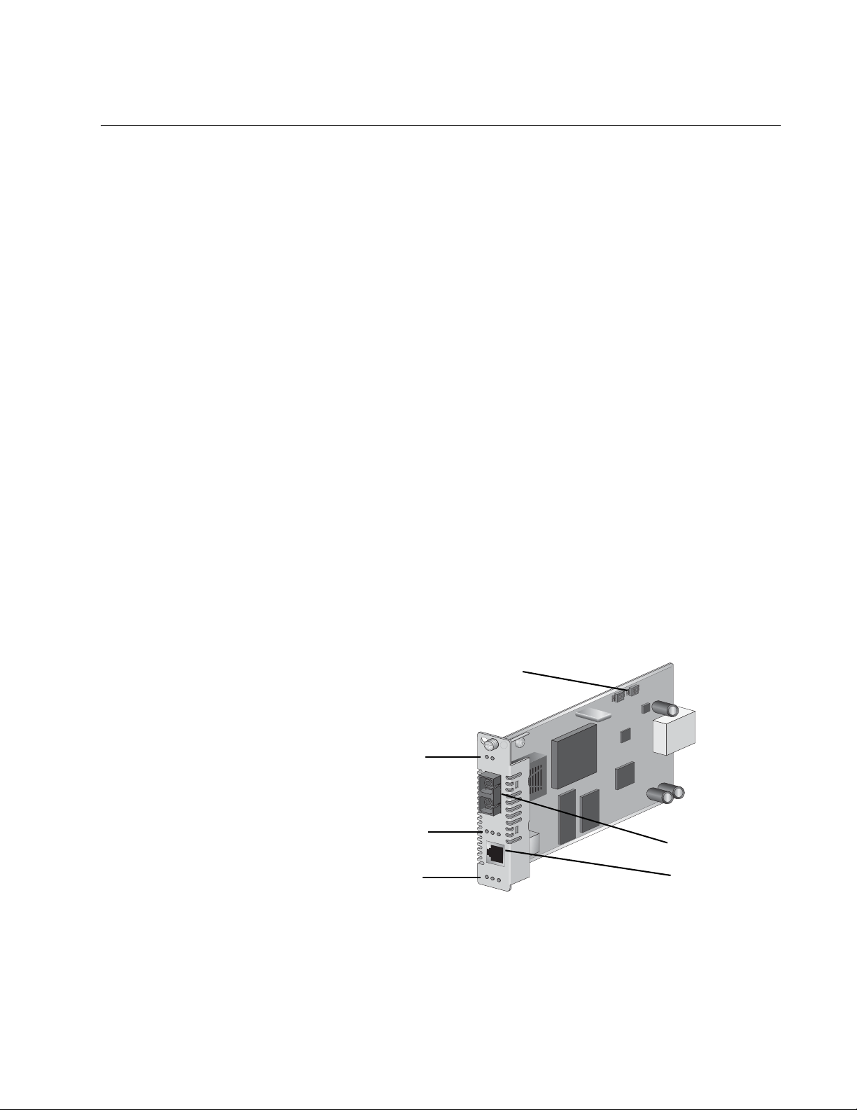
Each AT-CM20x Series line cards feature the following:
One 100Base-FX fiber optic port with a dual ST or SC connector
Refer to “100Base-FX Fiber Optic Ports” on page 27
One 10/100Base-TX twisted pair port with an RJ-45 connector
Refer to “10/100Base-TX Twisted Pair Ports” on page 29
Port and system status LEDs
Refer to “Fiber Optic Port LEDs” on page 38
DIP switches
Refer to “DIP Switches” on page 44
DIP Switches
1 2 3 4
K
3
1 2 3 4
1
W
S
K
3
2
W
S
Fiber Optic Port LEDs
Twisted Pair Port LEDs
Line Card LEDs
AT-CM202
LK
AT
LK
AT FD
T
X
RD
Y
SM
L
ML
T
X
M
M
R
X
OAM
246
Fiber Optic Port
RJ-45 Port
Figure 1. AT-CM202 Line Card
19
Page 20
Chapter 1: Converteon™ Fast Ethernet and Gigabit Ethernet Line Cards
AT-CM212x/1
Series
The AT-CM212x/1 Series (AT-CM212A/1 and AT-CM212B/1) are 100
Mbps copper-to-fiber media converter line cards. The line card contains
one fiber optic port and one copper twisted pair port. The fiber optic port
operates at a fixed operating speed of 100 megabits per second (Mbps)
and the twisted pair port operates at 10 or 100 Mbps speed. The fiber optic
port is IEEE 802.3ah-compliant and has a simplex SC connector with a
maximum operating distance of 15 kilometers (9.4 miles). The twisted pair
port has an RJ-45 connection and a maximum operating distance of 100
meters (328 feet). Both ports feature half- or full-duplex mode operation.
The line cards are hot-swappable into and out of the chassis.
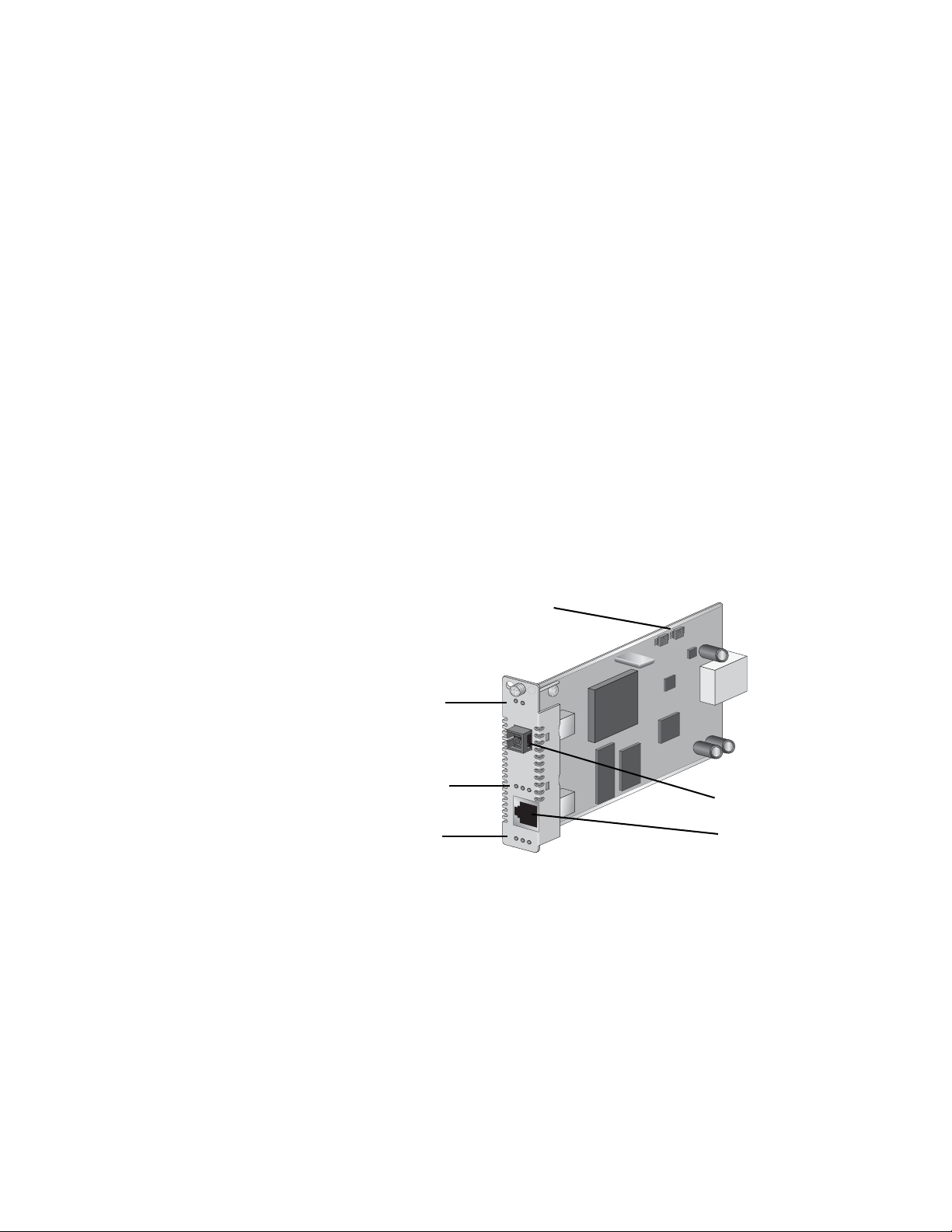
Each AT-CM212x/1 Series line card features the following:
One 100Base-FX fiber optic port with a simplex SC connector
Refer to “100Base-FX Fiber Optic Ports” on page 27
One 10/100Base-TX twisted pair port with an RJ-45 connector
Refer to “10/100Base-TX Twisted Pair Ports” on page 29
Port and system status LEDs
Refer to “Fiber Optic Port LEDs” on page 38
DIP switches
Refer to “DIP Switches” on page 44
Fiber Optic Port LEDs
Twisted Pair Port LEDs
Line Card LEDs
Figure 2. AT-CM212A/1 Line Card
DIP Switches
AT-CM212A/1
LK
A
T
F
X
LK A
T FD
T
X
R
DY
SML ML
OA
M
1 2 3 4
K
3
1 2 3 4
1
W
S
K
3
2
W
S
Fiber Optic Port
538
RJ-45 Port
20
Page 21
Converteon Media Converter Line Cards Reference Guide
A
T-CM2K0S
LK A
T
LK
AT
FD
1000M
R
DY
SFP
T
X
SML ML OA
M 1
00M
10/
100/
1000
AT-CM2K0S The AT-CM2K0S is a Gigabit copper-to-fiber media converter line card.
This line card can be installed in any of the Converteon™ Media Converter
chassis, including the AT-CV5000, AT-CV1000, and AT-CV1200. The line
card features one small form-factor pluggable (SFP) transceiver slot and
one copper twisted pair port. The SFP slot can accommodate one SFP
transceiver that operates at a fixed operating speed of one Gigabit. The
twisted pair port has an RJ-45 connector with a maximum operating
distance of 100 meters (328 feet) and operates at a speed of 10, 100, or
1000 megabits per second (Mbps). The line card is hot-swappable into
and out of the chassis.
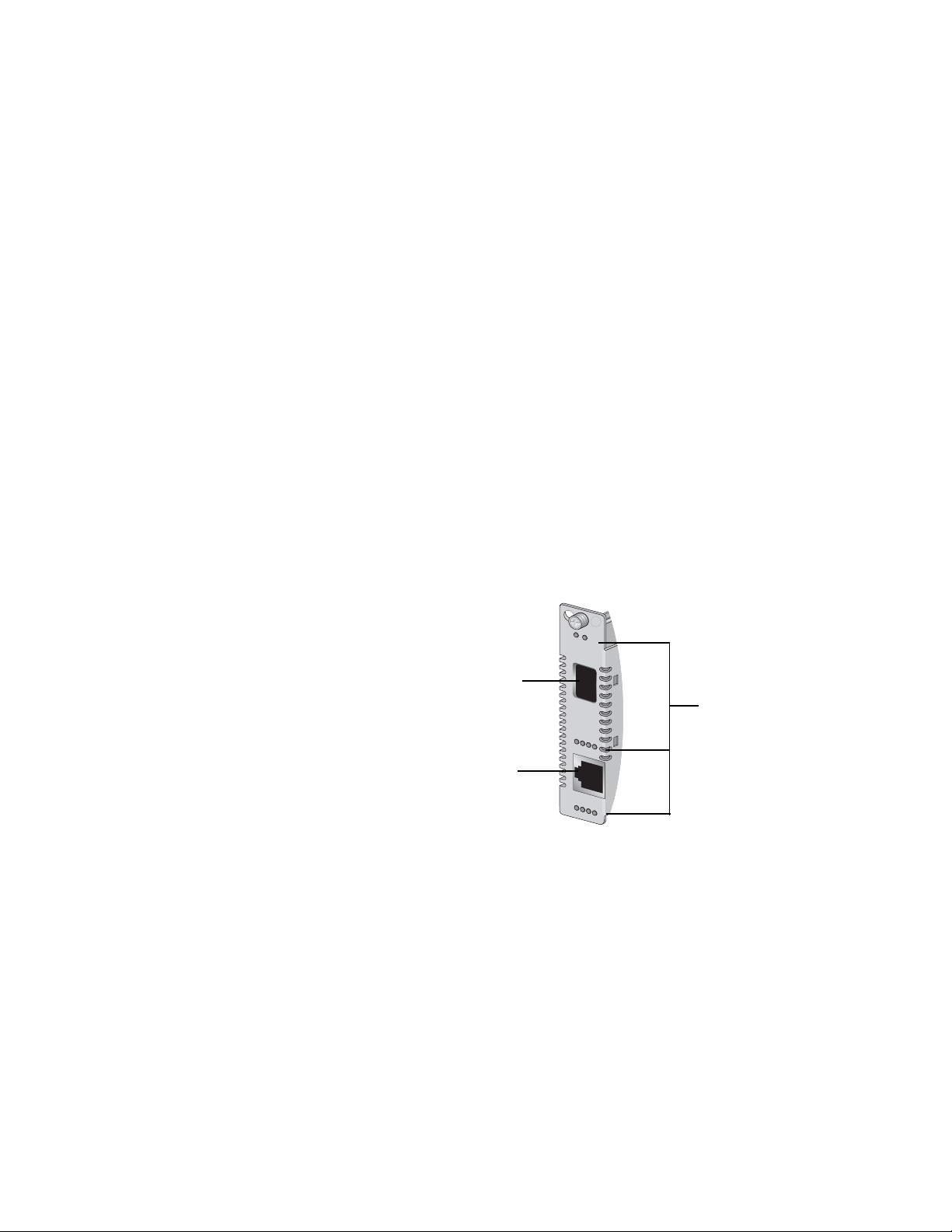
Each AT-CM2K0S line card features the following:
One SFP slot (SFP transceiver sold separately)
Refer to “SFP Expansion Slots” on page 35
One 10/100/1000Base-T twisted pair port with an RJ-45 connector
Refer to “10/100/1000Base-T Twisted Pair Ports” on page 31
Port and system status LEDs
Refer to “Fiber Optic Port LEDs” on page 38
DIP switches
Refer to “DIP Switches” on page 44
SFP Slot
RJ-45 Port
Figure 3. AT-CM2K0S Line Card
LEDs
525
21
Page 22
Chapter 1: Converteon™ Fast Ethernet and Gigabit Ethernet Line Cards
AT-CV10x Series The AT-CV10x Series (AT-CV101, AT-CV102, AT-CV102/1, and
AT-CV102/2) are 100 Mbps copper-to-fiber media converter line cards.
The line card features one fiber optic port and one copper twisted pair
port. Both ports operate at a fixed operating speed of 100 megabits per
second (Mbps). The fiber optic port is IEEE 802.3ah-compliant and has
either a dual ST or a dual SC connector with an operating distance of 2
kilometers (1.24 miles) to 40 kilometers (24.8 miles), depending on the
model. The twisted pair port has an RJ-45 connection and a maximum
operating distance of 100 meters (328 feet). Both ports feature half- or fullduplex mode operation. The line cards are hot-swappable into and out of
the chassis.
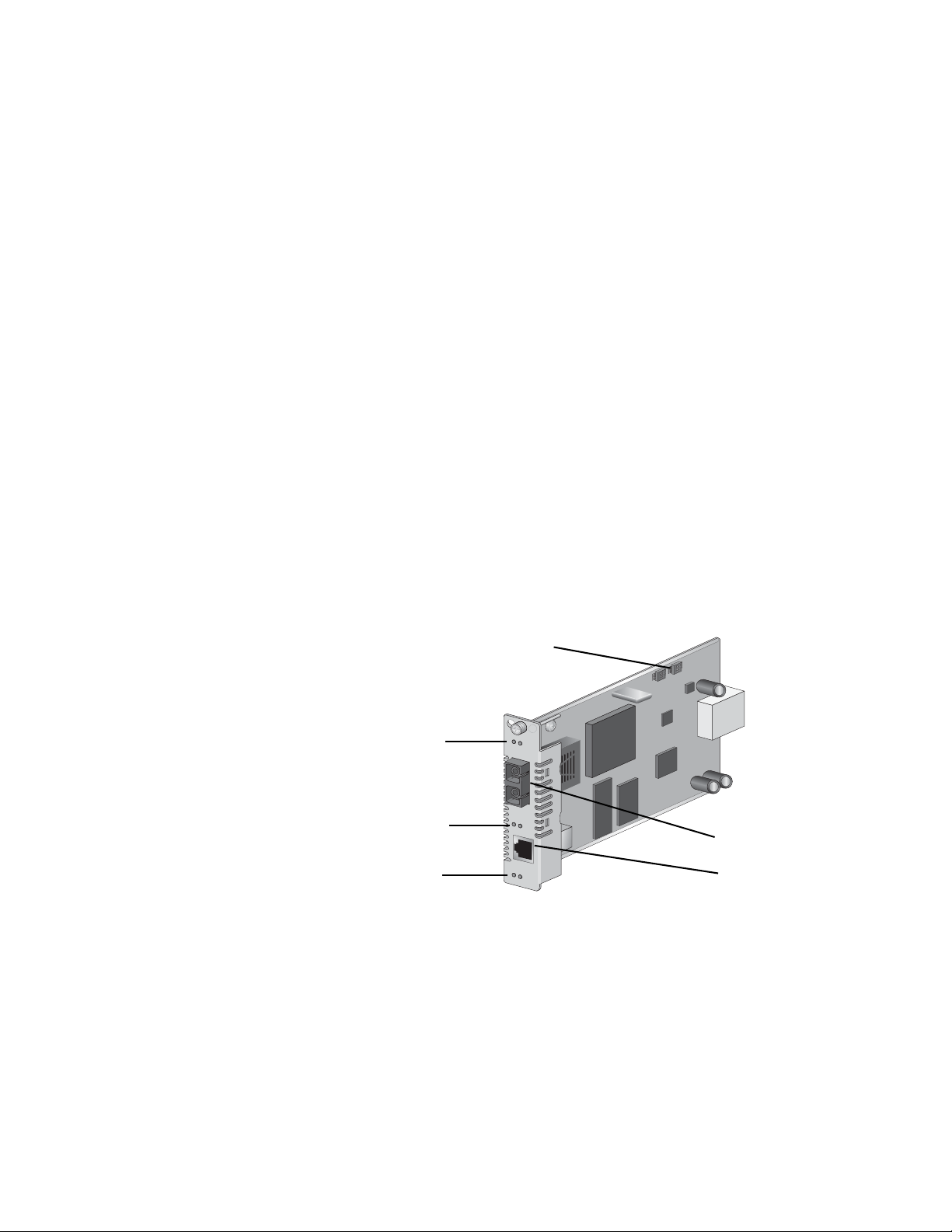
Each AT-CV10x Series line card features the following:
One 100Base-FX fiber optic port with a dual ST or a dual SC
connector
Refer to “100Base-FX Fiber Optic Ports” on page 27
One 100Base-TX twisted pair port with an RJ-45 connector
Refer to “100Base-FX Fiber Optic Ports” on page 27
Port and system status LEDs
Refer to “Fiber Optic Port LEDs” on page 38
DIP switches
Refer to “DIP Switches” on page 44
DIP Switches
Fiber Optic Port LEDs
Twisted Pair Port LEDs
Line Card LEDs
AT-CV102
LK
LK
T
X
R
D
Y
SM
L
AT
AT
M
L
T
X
M
M
R
X
Figure 4. Sample of an AT-CV10x Series Line Card
1 2 3 4
K
3
1 2 3 4
1
W
S
K
3
2
W
S
Fiber Optic Port
523
RJ-45 Port
22
Page 23

Converteon Media Converter Line Cards Reference Guide
Note
Restriction of Operation: While operating two AT-CV102 line cards
back-to-back, where both cards are in SML mode, if the fiber
connection between them is broken, remove the copper connection
to one of the AT-CV102 cards before restoring the fiber link between
them. Then wait at least 20 seconds before restoring the copper
connection.
23
Page 24
Chapter 1: Converteon™ Fast Ethernet and Gigabit Ethernet Line Cards
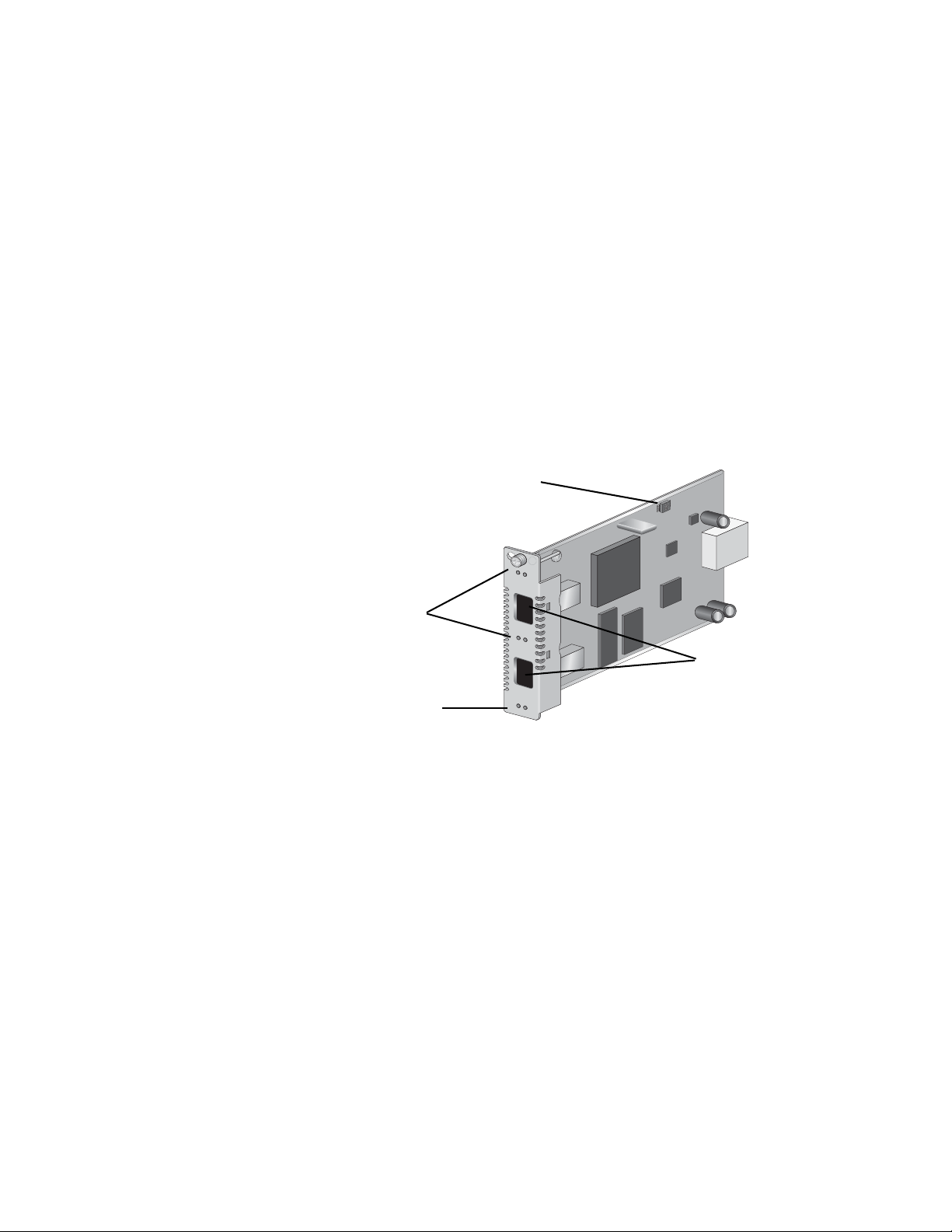
AT-CV1KSS The AT-CV1KSS, shown in Figure 5, is a Gigabit fiber-to-fiber media
converter line card used for Ethernet based networks. The line card
features two small form-factor pluggable (SFP) transceiver slots. Each
SFP slot can accommodate one SFP transceiver that operates at a fixed
operating speed of one Gigabit. The line cards are hot-swappable into and
out of the chassis.
Each AT-CV1KSS line card features the following:
Two SFP expansion slots (SFP transceiver sold separately)
Refer to “SFP Expansion Slots” on page 35
Port and system status LEDs
Refer to “Fiber Optic Port LEDs” on page 38
DIP switches
Refer to “DIP Switches” on page 44
DIP Switches
1 2 3 4
K
3
2
W
S
AT-CV1KS
S
L
K
A
T
S
F
SFP Transceiver LEDs
Line Card LEDs
P
LK
A
T
S
F
P
R
D
Y
S
M
L M
L
521
SFP Expansion Slots
Figure 5. AT-CV1KSS Line Card
The AT-CV1KSS line card features two SFP slots. Each SFP slot can
accommodate one fiber or one copper SFP transceiver that operates at a
fixed operating speed of one Gigabit.
For proper operation in the MissingLink™ and Smart MissingLink mode
configured with copper SFPs, the AT-CV1KSS requires to have copper
SFP transceiver that supports LOS (RXLOS) signal.
(For a list of SFP transceivers that can be used with the AT-CV1KSS line
card, refer to the Converteon™ Media Converter Line Cards Reference
Guide.)
24
Page 25
Converteon Media Converter Line Cards Reference Guide
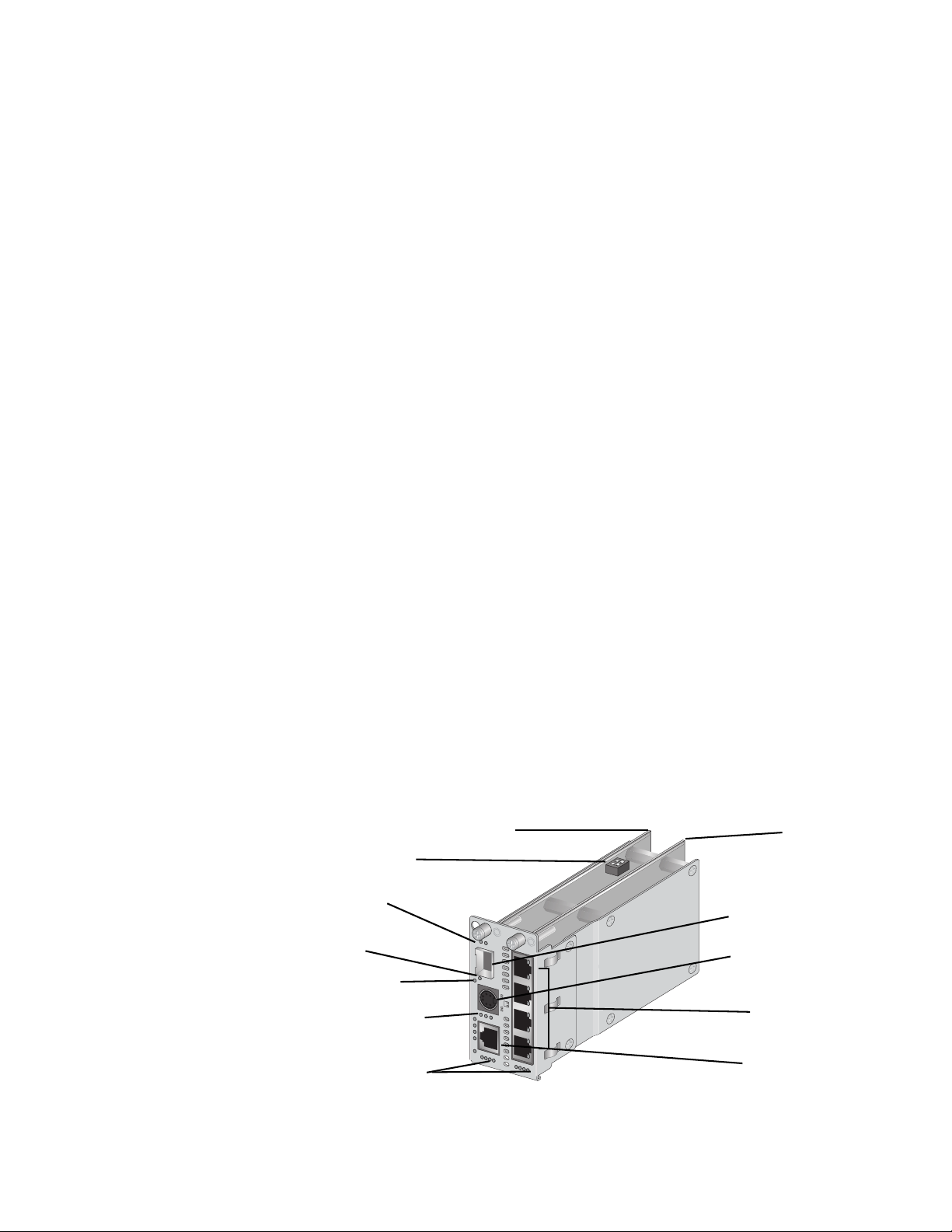
AT-CM70S The AT-CM70S is a 10/100 Mbps Ethernet copper-to-fiber media
converter line card with Time Division Multiplexing (TDM) (T1/E1)
transport in addition to regular Ethernet traffic along with OAM link
management capability. This line card offers support for 1.544 Mbps (T1)
and 2.048 Mbps (E1) services - with complete synchronization for tollquality transport of voice, video, and data. It also accommodates
traditional testing equipment currently used on SONET/SDH equipment for
testing T1/E1 services.
The AT-CM70S line card can be installed in the Converteon™ Media
Converter chassis, either the AT-CV5000 or the AT-CV1200. The line card
features one small form-factor pluggable (SFP) transceiver slot, one
copper twisted pair port, four T1/E1 ports, and one console (Mini-DIN)
port. The SFP slot can accommodate one SFP transceiver that operates at
a fixed operating speed of 100 megabits per second (Mbps). The twisted
pair port has an RJ-45 connector with a maximum operating distance of
100 meters (328 feet) and operates at a speed of 10 or 100 Mbps. The line
card is hot-swappable into and out of the chassis.
Each AT-CM70S line card features the following:
One RS-232 terminal port with an 8-pin Mini-DIN connector
Refer to “8-Pin Mini-DIN Console Port Pinouts” on page 93
One 10/100Base-TX twisted pair port with an RJ-45 connector
Refer to “10/100Base-TX Twisted Pair Ports” on page 29
One SFP expansion slots (SFP transceiver sold separately)
Refer to “SFP Expansion Slots” on page 35
Four T1/E1 ports with RJ-48 connectors
Refer to “T1/E1 Port (AT-CM70S Line Cards Only)” on page 33
Port and system status LEDs
Refer to “Fiber Optic Port LEDs” on page 38
DIP switches
Refer to “DIP Switches” on page 44
Base Board
Mezzanine
Adapter
DIP Switch
SFP Transceiver
LEDs
CPU RESET
Button
Console LEDs
Twisted Pair Port
LEDs
T1/E1 Port LEDs
AT-CM
R
DY
S
F
P
C
O
N
S
O
L
E
T
X
AIS 1
LK
O
A
CPU RESET
L/A FD 100
2
70
S
M
T1/E1
1
2
R
CL
NM
L
LO
TC
N
M
L
3
4
3
4
TEST
1
2
34
896
SFP Expansion Slot
Console Port
T1/E1 Ports
RJ-45 Port
Figure 6. AT-CM70S Line Card
25
Page 26

Chapter 1: Converteon™ Fast Ethernet and Gigabit Ethernet Line Cards
Hardware Features
The following sections describe these hardware features of the
Converteon™ media converter line cards:
“100Base-FX Fiber Optic Ports” on page 27
“10/100Base-TX Twisted Pair Ports” on page 29
“10/100/1000Base-T Twisted Pair Ports” on page 31
“T1/E1 Port (AT-CM70S Line Cards Only)” on page 33
“RS-232 Console Port (AT-CM70S Line Card Only)” on page 34
“SFP Expansion Slots” on page 35
“SFP Expansion Slots” on page 35
“Line Card and Port Status LEDs” on page 36
“DIP Switches” on page 44
“CPU RESET Button (AT-CM70S Line Card Only)” on page 56
“Blank Slot Covers” on page 57
26
Page 27

100Base-FX Fiber Optic Ports
The 100Base-FX fiber optic ports featured on the Converteon™ line cards
are described below.
Converteon Media Converter Line Cards Reference Guide
Type of
Connector
The fiber optic ports on the Converteon™ line cards feature either a
simplex SC, a dual SC, or a dual ST connector.
The connectors used on the line cards are listed as follows:
Dual ST Connector – AT-CM201, AT-CV101
Simplex SC Connector – AT-CM212x/1 Series
Dual SC Connector – AT-CM202, AT-CV102, AT-CV102/x Series
Speed The fiber optic ports are compliant with the 100Base-FX standard and
have a fixed operating speed of 100 Mbps. The speed cannot be changed.
The ports can send and receive on the following wavelengths:
AT-CM20x Series – TX/RX=1310 nm
AT-CM212A/1 – TX=1310 nm and RX=1550 nm
AT-CM212B/1 – TX=1550 nm and RX=1310 nm
AT-CV10x Series –TX/RX=1310 nm
Duplex Mode The fiber optic ports on the Converteon™ line cards can operate in either
half- or full-duplex mode. You can set the duplex mode manually using the
AT-S70 Management Software.
Maximum
Distance
The maximum operating distances of the fiber optic ports are listed below:
AT-CM202 – 2 kilometers (1.24 miles)
AT-CM202/1 – 15 kilometers (9.4 miles)
AT-CM202/2 – 40 kilometers (24.8 miles)
AT-CM212x/1 – 15 kilometers (9.4 miles)
AT-CV101 – 2 kilometers (1.24 miles)
AT-CV102 – 2 kilometers (1.24 miles)
AT-CV102/1 – 15 kilometers (9.4 miles)
AT-CV102/2 – 40 kilometers (24.8 miles)
27
Page 28

Chapter 1: Converteon™ Fast Ethernet and Gigabit Ethernet Line Cards
Type of Cable The fiber optic ports on the Converteon™ line cards use either a single-
mode (9/125 micron) or a multi-mode (50/125 or 62.5/125 micron) fiber
optic cable.
AT-CM202 – Multi-mode
AT-CM202/1 – Single-mode
AT-CM202/2 – Single-mode
AT-CM212x/1 – Single-mode
AT-CV101 – Multi-mode
AT-CV102 – Multi-mode
AT-CV102/1 – Multi-mode
AT-CV102/2 – Multi-mode
28
Page 29

10/100Base-TX Twisted Pair Ports
The 10/100Base-TX twisted pair ports featured on the Converteon™ line
cards are described below.
Converteon Media Converter Line Cards Reference Guide
Type of
Connector
The 10/100Base-TX twisted pair ports feature 8-pin RJ-45 connectors.
Only four of the pins are used when a port is operating at 10 or 100 Mbps.
For the port pinouts, refer to “RJ-45 Twisted Pair Port Pinouts” on page 89.
Speed The twisted pair ports are 10/100Base-TX compliant and are capable of
both 10 megabits per second (Mbps) and 100 Mbps speeds. Since the
ports are IEEE 802.3u Auto-Negotiation compliant, you can let the
converter set the port’s speed automatically. With Auto-Negotiation, the
converter automatically matches the highest possible common speed
between the converter port and the end-node. For example, if an endnode is capable of only 10 Mbps, the converter sets the port connected to
the end-node to 10 Mbps. Alternatively, you can set the port speed
through the management software.
Note
Auto-Negotiation is activated as the default on the twisted pair port
on the converter. To deactivate Auto-Negotiation and set the speeds
manually, refer to the AT-S70 Management Software User’s
Guide.
Duplex Mode The10/100Base-TX twisted pair ports on a Converteon™ line cards can
operate in either half- or full-duplex mode. The twisted pair ports are IEEE
802.3u-compliant and will Auto-Negotiate the duplex mode setting.
If desired, Auto-Negotiation on the converter ports can be disabled so that
you can set the duplex mode manually through the converter’s AT-S70
management software.
Maximum
Distance
The maximum operating distance of the 10/100Base-TX twisted pair ports
is 100 meters (328 feet).
Type of Cable For 10 Mbps, the port requires Category 3 or better (100 ohm shielded or
unshielded) twisted pair cabling. For 100 or 1000 Mbps, the port requires
Category 5 or Enhanced Category 5 (5E) (100 ohm shielded or
unshielded) twisted pair cabling.
29
Page 30

Chapter 1: Converteon™ Fast Ethernet and Gigabit Ethernet Line Cards
Auto MDI/
MDI-X
The 10/100Base-TX twisted pair ports are auto-MDI/MDI-X. They
automatically configure themselves as either MDI or MDI-X, depending on
the configuration of the port on the end node. This feature allows you to
use either straight-through or crossover twisted pair cables to connect
devices to the ports.
Note
The auto-MDI/MDI-X feature on a port is available only when the
port is set to Auto-Negotiation. If you disable Auto-Negotiation and
set a port’s speed and duplex mode manually, the port defaults to
MDI-X. For instructions on configuring a port, refer to the AT-S70
Management Software User’s Guide.
Port Pinouts For port pinouts when the port is operating at 10 or 100 Mbps in the MDI
configuration, refer to Table 20 on page 89.
For port pinouts when the port is operating at 10 or 100 Mbps in the MDI-X
configuration, refer to Table 21 on page 89.
30
Page 31

10/100/1000Base-T Twisted Pair Ports
The 10/100/1000Base-T twisted pair ports featured on the Converteon™
line cards are described below.
Converteon Media Converter Line Cards Reference Guide
Type of
Connector
The ports have 8-pin RJ-45 connectors. The ports use four pins when
operating at 10 or 100 Mbps and all eight pins when operating at 1000
Mbps.
Speed The ports can operate at 10, 100, or 1000 Mbps. The speed is set
automatically through Auto-Negotiation or you can set the speed to 10 or
100 Mbps manually through the management software.
Note
Auto-Negotiation is activated as the default on the twisted pair port
on the converter. To deactivate Auto-Negotiation and set the speeds
manually, refer to the AT-S70 Management Software User’s
Guide.
Duplex Mode The10/100/1000Base-T twisted pair ports on a Converteon™ line cards
can operate in either half- or full-duplex mode. The twisted pair ports are
IEEE 802.3u-compliant and will Auto-Negotiate the duplex mode setting.
If desired, Auto-Negotiation on the converter ports can be disabled so that
you can set the duplex mode manually through the converter’s AT-S70
management software.
Maximum
Distance
The10/100/1000Base-T twisted pair ports have a maximum operating
distance of 100 meters (328 feet).
Type of Cable For 10 Mbps, the port requires Category 3 or better 100 ohm shielded or
unshielded twisted pair cabling. For 100 or 1000 Mbps operation, the ports
require Category 5 or Enhanced Category 5 (5E) 100 ohm shielded or
unshielded twisted pair cabling.
Auto-MDI/
MDI-X
The10/100/1000Base-T twisted pair ports are auto-MDI/MDI-X. They
automatically configure themselves as either MDI or MDI-X. This feature
allows you to use a straight-through twisted pair cable to connect any type
of device to a port.
The auto-MDI/MDI-X feature on a 10/100/1000Base-T port is functional
only when the port is set to Auto-Negotiation. If you disable AutoNegotiation and set the port’s speed and duplex mode manually, the port
defaults to MDI-X. For instructions on configuring a port, refer to the
AT-S70 Management Software User’s Guides.
31
Page 32

Chapter 1: Converteon™ Fast Ethernet and Gigabit Ethernet Line Cards
Port Pinouts For the pinouts of these ports when operating at 10 or 100 Mbps, refer to
Table 10 on page 82. For port pinouts when the ports are operating at
1000 Mbps, refer to Table 12 on page 84.
32
Page 33

T1/E1 Port (AT-CM70S Line Cards Only)
The T1/E1 twisted pair ports featured on the AT-CM70S line cards are
described below.
Converteon Media Converter Line Cards Reference Guide
Type of
Connector
The T1/E1 ports on the AT-CM70S line cards feature 8-pin RJ-48
connectors. For the port pinouts, refer to “RJ-48 T1/E1 Port Pinouts” on
page 91.
Speed The constant bit rate transport of full or fractional T1 frame is 1.544 Mbps.
The constant bit rate transport of full or fractional E1 frame is 2.048 Mbps.
Type of Cable The T1/E1 ports on the AT-CM70S line cards use the twisted pair cabling.
33
Page 34

Chapter 1: Converteon™ Fast Ethernet and Gigabit Ethernet Line Cards
RS-232 Console Port (AT-CM70S Line Card Only)
You can use the console port on the AT-CM70S line card to establish a
local (out-of-band) management session with the chassis to configure
parameters and also view information about the operating of the system
and line cards. You establish a local management session with the
converter by connecting either a terminal, or a personal computer with a
terminal emulation program, to the port.
Note
For more information how to start a management session, refer to
the installation guide that comes with the chassis.
Note
If an AT-CM70S line card is used in an AT-CV5000 chassis, it can
be managed either from its local console or from the console port on
the AT-CV5M01 CPM module. However, if this line card is used in
an AT-CV1200 chassis, it can only be managed from its local
console, as there is no room for an AT-CV5M01 CPM module.
Type of
Connector
The RS-232 console port on the AT-CM70S line card features 8-pin MiniDIN connectors. For the port pinouts, refer to “8-Pin Mini-DIN Console
Port Pinouts” on page 93.
Specifications The console port has a Mini-DIN style connector and is set to the following
specifications:
Baud rate: 115200 bps
Data bits: 8
Parity: None
Stop bits: 1
Type of Cable The console port on the AT-CM70S line card use the RS-232 serial cable.
Note
You can use the AT-S70 management software to change the
terminal port settings.
34
Page 35

SFP Expansion Slots
The SFP expansion slots featured on the Converteon™ line cards are
described below.
The SFP modules are a fast and easy way for you to add an 1000 Mbps
fiber optic port. You can use the modules to extend the distance of your
network, build a high-speed backbone network between devices, or
connect additional end nodes to the network, such as high-speed servers.
Figure 7 shows an example of a fiber optic SFP transceiver module.
Converteon Media Converter Line Cards Reference Guide
482
SFP Transceivers
Supported by
AT-CV1KSS and
AT-CM2K0S
Line Cards
Figure 7. SFP Transceiver Module
Note
For a list of the SFP transceivers supported by the Converteon™
line cards, please refer to the Installation Guides shipped with the
respective line cards.
The AT-CV1KSS line card features two SFP slots. Each SFP slot can
accommodate one fiber or one copper SFP transceiver that operates at a
fixed operating speed of one Gigabit.
The AT-CM2K0S line card features one SFP slot that operates at a fixed
operating speed of one Gigabit.
35
Page 36

Chapter 1: Converteon™ Fast Ethernet and Gigabit Ethernet Line Cards
Line Card and Port Status LEDs
Line Card Status
LEDs
The front panels of the Converteon™ line cards have different status
LEDs, depending on the model. These LEDs display the status
information of the line cards.
Table 2 lists the line card status LEDs, except for AT-CM70S line cards.
For LEDs on the AT-CM70S line cards, refer to Table 3 on page 37.
For additional information on how the Link Test (LK), MissingLink (ML),
and Smart MissingLink (SML) LEDs function on the Converteon™ line
cards, refer to “Link Test, MissingLink™, and Smart MissingLink LED
Functionalities” on page 98.
Table 2. Line Card Status LEDs
LED State Description
RDY Green The line card has passed diagnostics.
OFF The line card has failed diagnostics.
SML Green The Smart MissingLink mode on the line
card is enabled.
OFF The Smart MissingLink mode on the line
card is disabled.
ML Green The MissingLink™ mode on the line
card is enabled.
OFF The MissingLink™ mode on the line
card is disabled.
1
OAM
1. This LED does not display on the AT-CV Series line cards.
Green The OAM mode on the line card is
enabled. The OAM mode setting is set
by the DIP Switches. For more
information, refer to Table 12, ”ATCM20x Series and AT-CM212x/1 Series
– Diagnostic Mode DIP Switch 1
Positions” on page 50.
OFF The OAM mode on the line card is
disabled.
36
Page 37

Converteon Media Converter Line Cards Reference Guide
Table 3 lists the status LEDs on the AT-CM70S line card.
Table 3. AT-CM70S Line Card Status LEDs
LED State Description
RDY Green The line card has passed diagnostics.
OFF The line card has not passed
diagnostics.
1
CONSOLE
Green The line card is managed from its local
console.
OFF The line card is managed from the CPM
module located on the chassis.
1. This LED only works when the AT-CM70S line card is used in the AT-CV5000
chasis.
37
Page 38

Chapter 1: Converteon™ Fast Ethernet and Gigabit Ethernet Line Cards
Fiber Optic Port
LEDs
Table 4 lists the fiber optic port LEDs, except for AT-CM70S line card. For
LEDs on the AT-CM70S line card, refer to Table 5.
Table 4. Line Card Fiber Optic Port LEDs
LED State Description
LK Green Link established on the fiber optic port.
Blinking
Green
OFF No link established on the fiber optic
AT Blinking
Green
OFF No activity detected on the fiber optic
Table 5 lists the fiber optic port LEDs on the AT-CM70S line card.
Table 5. AT-CM70S - Fiber Optic Port LEDs
While in Smart MissingLink mode, a
valid connection is established on the
port while a link on the other port is lost.
port.
TX/RX activity detected on the fiber optic
port.
port.
LED State Description
LK Green Link established on the fiber optic port.
OFF No link established on the fiber optic
port.
OAM Green The OAM mode is enabled (visible or
bypass) and can be set by the the DIP
switches.
OFF The OAM mode is disabled.
38
Page 39

Converteon Media Converter Line Cards Reference Guide
Twisted Pair Port
LEDs
Table 6 lists the twisted pair port LEDs, except for AT-CM70S line card.
For LEDs on the AT-CM70S line card, refer to Table 7.
Table 6. Line Card Twisted Pair Port LEDs
LED State Description
LK Green Link established on the port.
OFF No link established on the port.
AT Blinking
TX/RX activity detected on the port.
Green
OFF No activity detected on the port.
FD
1
Green The TX port is operating in full-duplex
mode.
OFF The TX port is operating in half-duplex
mode.
100M
2
Green The port is operating at 100 Mbps.
OFF
3
The TX port is operating at 10 Mbps.
1000M
2
1. This LED does not display on the AT-CV Series line cards.
2. These LEDs only display on the AT-CM2K0S line card.
3. When both 100M and 1000M LEDs are off, the port is operating at 10 Mbps.
Green The TX port is operating at 1 Gigabit.
OFF
3
The TX port is operating at 10 Mbps.
Table 7 lists the twisted pair port LEDs on the AT-CM70S line card.
Table 7. AT-CM70S - Twisted Pair Port LEDs
LED State Description
L/A Green The TX port has established a valid link.
Blinking
The TX port has detected TX/RX activity.
Green
FD Green The TX port is operating in full-duplex
mode.
OFF The TX port is operating in half-duplex
mode (intermittently ON when there is
collision).
39
Page 40

Chapter 1: Converteon™ Fast Ethernet and Gigabit Ethernet Line Cards
Table 7. AT-CM70S - Twisted Pair Port LEDs
LED State Description
100 Green The TX port is operating at 100 Mbps
OFF The TX port is operating at 10 Mbps
speed.
speed.
40
Page 41

Converteon Media Converter Line Cards Reference Guide
T1/E1 Port LEDs Table 9 lists the T1/E1 surface-mount diagnostic LED’s provisioned on the
Mezzanine Adapter and are viewable through the line card front panel.
Table 8. T1/E1 Port LEDs
LED State Description
RCL
[1 to 4]
LOTC
[1 to 4]
AIS
[1 to 4]
TEST
[1 to 4]
Amber Receive Carrier Loss occurred on the
T1/E1 port.
Green The T1/E1 port is operating normally
(NML) and has no Receive Carrier Loss.
Amber Loss of Transmit Clock occurred on the
T1/E1 port.
Green The T1/E1 port is operating normally
(NML) and has no Loss of Transmit
Clock.
Amber The T1/E1 has received Unframed All
Ones.
OFF The T1/E1 port is operating normally
(NML) and no AIS received.
Green T1/E1 port is synchronized to PRBS test
15
stream: 2
-1 (E1) or QRSS (T1).
OFF PRBS test stream not detected on the
T1/E1 port.
41
Page 42

Chapter 1: Converteon™ Fast Ethernet and Gigabit Ethernet Line Cards
Serial Port LEDs Table 9 lists the serial port LED’s provisioned on the Mezzanine Adapter
and are viewable through the line card front panel.
LED Color Description
SER MODE
[1 to 4]
SER ACT
[1 to 4]
Green The serial port is operating in RS-232 mode.
OFF The serial port is operating in RS-422/485
mode.
Green The serial port has established a valid link.
OFF The serial port has detected TX/RX activity.
42
Page 43

Converteon Media Converter Line Cards Reference Guide
SFP Transceiver
LEDs
Table 9 lists the SFP transceiver LEDs, except for AT-CM70S line cards.
For LEDs on the AT-CM70S line cards, refer to Table 10
Table 9. SFP Transceiver LEDs
LED State Description
LK Green Link established on the port.
OFF No link established on the port.
AT Blinking
Green
OFF No activity detected on the port.
Table 10 lists the SFP transceiver LEDs on the AT-CM70S line card.
Table 10. AT-CM70S - SFP Transceiver LEDs
LED State Description
LK Green Link established on the port.
OFF No link established on the port.
TX/RX activity detected on the port.
.
OAM Green The OAM mode is enabled (visible or
bypass) and can be set by the the DIP
switches.
OFF The OAM mode is disabled.
43
Page 44

Chapter 1: Converteon™ Fast Ethernet and Gigabit Ethernet Line Cards
DIP Switches
Some of the Converteon™ line cards support the following features by
configuring their DIP switches:
Link Test
MissingLink™ Mode
Smart MissingLink Mode
OAM Capability
Note
For additional information on how the Link Test (LK), MissingLink
(ML), and Smart MissingLink (SML) LEDs function on the
Converteon™ line cards, refer to “Link Test, MissingLink™, and
Smart MissingLink LED Functionalities” on page 98.
Link Test The link test is a fast and easy way for you to test the connections
between the converter ports and the end-nodes that are connected to the
ports. If a network problem occurs, you can perform a link test to
determine which port is experiencing a problem, and so be able to focus
your troubleshooting efforts on the cable and end-node where the problem
resides.
The LK LED for the twisted pair port should be green, indicating that it was
able to establish a link with its end-nodes. If the LK LED is off, the port
could not establish a link. Refer to “Troubleshooting” on page 83 for
suggestions on how to remedy the problem.
For more information on how the LK LED functions, refer to “Link Test,
MissingLink™, and Smart MissingLink LED Functionalities” on page 98.
Performing a link test does not interfere with a converter’s ability to pass
network traffic.
MissingLink™ The MissingLink™ feature enables the ports on the media converter to
pass the “Link” status of their connections to each other. When the media
converter detects a problem on one of the ports, such as the loss of
connection to an end-node, the media converter shuts down the
connection to the other port, thus notifying the end-node that the
connection has been lost.
For more information on how the ML LED functions, refer to “Link Test,
MissingLink™, and Smart MissingLink LED Functionalities” on page 98.
For example, if the twisted pair cable to the 10/100Base-TX port on the
media converter were to fail, the unit would respond by dropping the link
44
Page 45

Converteon Media Converter Line Cards Reference Guide
on the 100Base-FX fiber optic port. In this way, the media converter
notifies the end-node connected to the fiber optic port that the connection
on the twisted pair port has been lost. If the failure had started with the
fiber optic cabling, the unit would drop the link to the twisted pair port.
The value to this type of network monitoring and fault notification is that
some devices can be configured to take a specific action in the event of
the loss of connection on a port. In some cases, the unit can be configured
to seek a redundant path to a disconnected end-node or send out a trap to
a network management station, and so alert the network administrator of
the problem.
Smart
MissingLink
The Smart MissingLink feature performs exactly the same function as
MissingLink™ with one additional feature. When a link is lost on a port, the
LK LED of the port that still has a valid connection to its end-node starts to
blink. This allows you to quickly determine which port still has a valid
connection (LK LED blinking) and which port has lost its connection (LK
LED Off).
For more information on how the SML LED functions, refer to “Link Test,
MissingLink™, and Smart MissingLink LED Functionalities” on page 98.
For example, if the network twisted pair cable to the 10/100Base-TX port
on the media converter fails, the LK LED on the 100Base-FX fiber optic
port blinks, indicating a failed connection on the twisted pair port. If the
failure starts with the fiber optic cabling, the LK LED on the twisted pair
port blinks.
The value to this type of network monitoring and fault notification is so that
you can quickly see which port has failed and troubleshoot your network
accordingly.
OAM Overview OAM refers to the tools and utilities to install, monitor, test, and trouble-
shoot a network, helping carriers run their networks more efficiently.
Without management features to monitor and troubleshoot the network, it
is rather expensive and time consuming to have the problems diagnosed
and resolved by having the technicians coming out to the location.
In the enterprise, Ethernet links and networks have been managed via
SNMP. Although SNMP provides a very flexible management solution, it is
not always efficient and is sometimes inadequate to the task. First, using
SNMP assumes that the underlying network is operational because SNMP
relies on IP connectivity; however, you need management functionality
even more when the underlying network is non-operational. Second,
SNMP assumes every station is IP accessible. This requires provisioning
IP on every station and instituting an IP overlay network even if the
ultimate end-user service is an Ethernet service. This is impractical in a
carrier environment.
45
Page 46

Chapter 1: Converteon™ Fast Ethernet and Gigabit Ethernet Line Cards
For these reasons, carriers look for management capabilities at every
layer of the network. The Ethernet layer has not traditionally offered
inherent management capabilities, so the 802.3ah OAM capabilities act as
a first step at providing them. 802.3ah OAM is applicable to the following
Ethernet in the First Mile (EFM) technologies:
Ethernet in the First Mile over Copper (EFMC)
Ethernet in the First Mile over Fiber (EFMF)
Ethernet in the First Mile using Passive Optical Networks (EPON)
Note
Note that these capabilities are not intended to replace SNMP as a
management utilities, but are there to enhance it.
Network operators have the freedom to choose and mix the three EFM
topologies (copper, fiber, or passive optical networking) based on their
business models, network architectures, and subscriber needs. They can
configure and upgrade their access networks with multiple EFM topologies
and manage them with a common set of tools and OAM procedures.
Additionally, EFM OAM is backwards compatible with any existing fullduplex Ethernet technology, and can be implemented on non-EFM
Ethernet links. This compatibility was facilitated by the decision to use
standard Ethernet frames as the transport mechanism for management
information.
OAM Main Features
Although EFM OAM is compatible with any Ethernet technology and can
be used on even small campus networks, it is geared towards reducing
expenditures for first mile operators. The OAM work of the IEEE 802.3ah
task force addresses three key operational issues when deploying
Ethernet across geographically disparate locations: link performance
monitoring, fault detection and fault signaling, and loopback testing.
Link Performance Monitoring – Introduces some basic error definitions
for Ethernet so entities can detect failed and degraded connections.
Fault Detection and Fault Signaling – Provides mechanisms for one
entity to signal another that it has detected an error.
Loopback Testing – Is often used to troubleshoot networks, allows one
station to put the other station into a state whereby all inbound traffic is
immediately reflected back onto the link.
46
Page 47

Converteon Media Converter Line Cards Reference Guide
OAM Protocol
The operation of OAM on an Ethernet interface does not adversely affect
data traffic as OAM is a slow protocol with very limited bandwidth potential,
and it is not required for normal link operation. This slow protocol can be
implemented in hardware or software, ensuring media independence. By
utilizing the slow protocol MAC address, OAM frames are intercepted by
the MAC sublayer and cannot propagate across multiple hops in an
Ethernet network. This implementation assures that OAM Protocol Data
Units (OAMPDUs) only affect the operation of the OAM protocol itself and
not user data traffic.
OAMPDU Types
The architecture of the OAM protocol is based on OAMPDU, which are
exchanged between two Ethernet ports. OAMPDUs are normal Ethernet
frames that use a specific multicast destination address and EtherType.
Most of the OAMPDU types also define a set of standard type-length-value
(TLV) encoding of attributes within the type.
Information OAMPDUs
Information OAMPDUs are used for discovery; they are variable-length
OAMPDUs.
The different TLVs for Information PDUs are Local Information,
Remote Information, and Organizational Specific.
Local and Remote Information is used in the discovery process. The
Organizational Specific Information TLV is used for vendor extensions.
It is encoded here because the source MAC address is not a simple
indication of organization identification as many organizations have
multiple OUIs assigned. The 32-bit vendor specific information is not
defined and is used to encode the model or version of the platform.
The platform identity held is intended to allow simple identification of
the hardware device.
Event OAMPDUs
The data field in the Event OAMPDUs contains one or more link event
TLVs. This variable-length PDU is used for link monitoring.
The link event TLVs may be sent multiple times to increase the
likelihood of reception (for example, in the case of high bit-errors).
These TLVs may include a time reference when generated.
Loopback Control OAMPDUs
The Loopback Control OAMPDU provides the loopback command.
Variable Request/Response OAMPDUs
The variables accessible through OAM must be in the Ethernet branch
of the MIB tree. The process of variable retrieval involves transferring
Ethernet counters and statistics via Variable Containers/Descriptors.
47
Page 48

Chapter 1: Converteon™ Fast Ethernet and Gigabit Ethernet Line Cards
Organizational Specific OAMPDUs
Organizations may define events that are of variable-length and are
distinguish by the OUI. This is a variable-length TLV.
Unsupported OAMPDUs
Unknown/unsupported OAMPDUs are sent to the OAM Client. This is
different from typical Ethernet (802.3x) behavior, which filtered
unsupported opcodes.
OAM Discovery
Discovery is the first phase of the IEEE 802.3ah OAM protocol, and relies
on what are termed information OAMPDUs. During discovery, information
about OAM entities capabilities, configuration, and identity are exchanged.
The discovery process allows a local Data Terminating Entity (DTE) to
detect OAM on a remote DTE. Once OAM support is detected, both ends
of the link exchange state and configuration information (such as mode,
PDU size, loopback support, etc.). If both DTEs are satisfied with the
settings, OAM is enabled on the link. However, the loss of a link or a
failure to receive OAMPDUs for five seconds may cause the discovery
process to restart.
This is one important aspect of the IEEE 802.3ah OAM spec is that an
OAM entity may be in either Active or Passive mode.
Active Mode – Active-mode DTEs instigate OAM communications
and can issue queries and commands to a remote station.
Passive Mode – Passive-mode DTEs generally wait for the peer
station to instigate OAM communications and respond to, but do not
instigate, commands and queries.
By default, the card should come up in Passive mode for OAM discovery
(as per the IEEE 802.3ah). In order to initiate OAM discovery, the card
should change from Passive mode to Active mode by the CPM card within
a chassis. Therefore, if a line card is in a chassis with no CPM card, it
should come up in Passive mode.
The difference between the modes is that an active-mode station can
exert more control on its peer than a passive-mode station. For example,
an active-mode OAM entity can put a passive-mode OAM entity into
loopback mode, but not vice versa.
48
Page 49

Converteon Media Converter Line Cards Reference Guide
Table 11 lists the OAM Active and OAM Passive mode behaviors.
Table 11. OAM Active and Passive Mode Behaviors
Capability
Active
DTE
Passive
DTE
Initiates OAM Discovery process Yes No
Reacts to OAM Discovery process initiation Yes Yes
Required to send Information OAMPDUs Yes Yes
Permitted to send Event Notification OAMPDUs Yes Yes
Permitted to send Variable Request OAMPDUs Yes No
Permitted to send Variable Response OAMPDUs Yes* Yes
Permitted to send Loopback Control OAMPDUs Yes No
Reacts to Loopback Control OAMPDUs Yes* Yes
Permitted to send Organization Specific
Yes Yes
OAMPDUs
* Requires the peer DTE to be in Active mode.
OAM Loopback
OAM provides a data link layer frame-level loopback mode, which is
controlled remotely. Loopback is used to test the performance of a link.
Statistics from both the local and remote station can be queried and
compared at any time while the remote station is in OAM loopback mode.
These queries can take place before, during, or after loopback frames
have been sent to the remote station. In addition, an implementation may
analyze loopback frames to determine additional information about the
health of the link (in example, determine which frames are being dropped
due to link errors).
The Converteon™ line cards feature one or two sets of DIP switches,
depending on the model. The DIP switches are Diagnostic Mode and Port
Configuration DIP switches.
The Diagnostic Mode DIP switches are used to configure the
diagnostic mode positions of the line card.
The Port Configuration DIP switches are used to manually configure
the operating characteristics of the twisted pair port.
49
Page 50

Chapter 1: Converteon™ Fast Ethernet and Gigabit Ethernet Line Cards
3K
1 2 3 4
3K
1 2 3 4
SW1
SW2
3K
1 2 3 4
SW2
3K
1 2 3 4
SW1
AT-CM20x Series
and
AT-CM212x/1
Series Line Cards
The AT-CM20x Series line card, shown in Figure 8, and AT-CM2121x/1
Series line card, shown in Figure 9, feature both the Diagnostic Mode DIP
Switch 1 and Port Configuration DIP Switch 2.
Diagnostic Mode
Port Configuration
DIP Switch 1
DIP Switch 2
1 2 3 4
K
3
1 2 3 4
1
SW
K
3
2
SW
AT-CM
202
LK
AT
T
X
M
M
R
X
LK
AT FD
T
X
R
D
Y
SML
M
L O
AM
289
Figure 8. DIP Switches on an AT-CM20x Series Line Card (AT-CM202)
Diagnostic Mode
Port Configuration
DIP Switch 1
DIP Switch 2
1 2 3 4
K
3
1 2 3 4
1
W
S
K
3
2
W
S
AT-CM212A/1
L
K
AT
F
X
LK AT FD
T
X
R
DY
SML ML OA
M
541
Figure 9. DIP Switches on an AT-CM212x/1 Series Line Card
Table 12 lists the positions of the Diagnostic Mode DIP Switch 1 on the
AT-CM20x Series and AT-CM212x/1 Series line cards.
Table 12. AT-CM20x Series and AT-CM212x/1 Series – Diagnostic Mode
DIP Switch 1 Positions
Operating Mode DIP 1 DIP 2 DIP 3 DIP 4
Smart MissingLink (SML) OFF ON ON X
MissingLink™ (ML) OFF OFF ON X
OAM Bypass ON OFF OFF X
50
Page 51

Converteon Media Converter Line Cards Reference Guide
Table 12. AT-CM20x Series and AT-CM212x/1 Series – Diagnostic Mode
DIP Switch 1 Positions
Operating Mode DIP 1 DIP 2 DIP 3 DIP 4
OAM Visible ON ON OFF X
Link Test (default) OFF OFF OFF X
Manufacturing Default Settings OFF OFF OFF OFF
“X” means the DIP switch position could be either ON or OFF.
Table 13 lists the positions of the Port Configuration DIP Switch 2 for the
twisted pair port on the AT-CM20x Series and AT-CM212x/1 Series line
cards.
Table 13. AT-CM20x Series and AT-CM212x/1 Series – Port Configuration
DIP Switch 2 Positions
Operating Mode DIP 1 DIP 2 DIP 3 DIP 4
Auto MDI-X Enable (default) X OFF X X
Auto MDI-X Disable X ON X X
Manufacturing Default Settings OFF OFF OFF OFF
“X” means the DIP switch position could be either ON or OFF.
51
Page 52

Chapter 1: Converteon™ Fast Ethernet and Gigabit Ethernet Line Cards
3K
1 2 3 4
3K
1 2 3 4
SW1
SW2
AT-CV10x Series
Line Cards
The AT-CV10x series line cards, shown in Figure 11, feature both
Diagnostic Mode DIP Switch 1 and Port Configuration DIP Switch 2.
Diagnostic Mode
Port Configuration
DIP Switches 1
DIP Switches 2
1 2 3 4
K
3
1 2 3 4
1
W
S
K
3
2
W
S
AT-
CM202
LK
AT
T
X
M
M
R
X
LK
AT FD
T
X
RDY
S
M
L
M
L
O
A
M
289
Figure 10. DIP Switches on an AT-CM20x Series Line Card
Table 16 lists the positions of the Diagnostic Mode DIP Switch 1 for the
twisted pair port on the AT-CV10x Series line card.
Table 14. AT-CV10x Series – Diagnostic Mode DIP Switch 1 Positions
Operating Mode DIP 1 DIP 2 DIP 3 DIP 4
Link Test (default) OFF OFF X X
Smart MissingLink (SML) OFF ON X X
MissingLink™ (ML) ON OFF X X
Manufacturing Default Settings OFF OFF OFF OFF
“X” means the DIP switch position could be either ON or OFF.
Table 15 lists the positions of the Port Configuration DIP Switch 2 for the
twisted pair port on the AT-CV102 line card.
Table 15. AT-CV10x Series – Port Configuration DIP Switch 2 Positions
Operating Mode DIP 1 DIP 2 DIP 3 DIP 4
Auto MDI-X Enabled (default) X OFF X X
Manufacturing Default Settings OFF OFF OFF OFF
“X” means the DIP switch position could be either ON or OFF.
52
Page 53

Converteon Media Converter Line Cards Reference Guide
3K
1 2 3 4
SW2
AT-CM2K0S
Line Card
The AT-CM2K0S line card, shown in Figure 11, feature only the
Diagnostic Mode DIP Switch.
Diagnostic Mode
DIP Switch
1 2 3 4
K
3
2
SW
A
T-CM
2K0
S
LK
AT
SFP
LK
A
T
F
D
1000
M
T
X
R
D
Y
10
/
1
00
/
10
0
0
S
M
L
M
L
O
AM
1
00
M
536
Figure 11. DIP Switch on an AT-CM2K0S Line Card
Table 16 lists the positions of the Diagnostic Mode DIP Switch for the
twisted pair port on the AT-CM2K0S line card.
Table 16. AT-CM2K0S – Diagnostic Mode DIP Switch Positions
Operating Mode DIP 1 DIP 2 DIP 3 DIP 4
Smart MissingLink (SML) OFF ON ON X
MissingLink (ML) OFF OFF ON X
OAM Bypass ON OFF OFF X
OAM Visible ON ON OFF X
Link Test (default) OFF OFF OFF OFF
“X” means the DIP switch position could be either ON or OFF.
53
Page 54

Chapter 1: Converteon™ Fast Ethernet and Gigabit Ethernet Line Cards
3K
1 2 3 4
SW2
AT-CV1KSS
Line Card
The AT-CV1KSS line card, shown in Figure 12, features only the
Diagnostic Mode DIP Switch.
Diagnostic Mode
DIP Switch
1 2 3 4
K
3
2
SW
A
T-CV1KS
S
L
K A
T
S
F
P
LK
A
T
S
F
P
R
DY
SML ML
537
Figure 12. DIP Switches on an AT-CV1KSS Line Card
Table 17 lists the positions of the Diagnostic Mode DIP Switch on an
AT-CM2K0S line card.
Table 17. AT-CV1KSS – Diagnostic Mode DIP Switch Positions
Operating Mode DIP 1 DIP 2 DIP 3
Smart MissingLink (SML) OFF ON X
MissingLink™ (ML) ON OFF X
Link Test (default) OFF OFF X
Manufacturing Default Settings OFF OFF OFF
“X” means the DIP switch position could be either ON or OFF.
54
Page 55

Converteon Media Converter Line Cards Reference Guide
AT-CM70S Line
Card
The AT-CM70S line card, shown in Figure 13, features only the Diagnostic
Mode DIP Switch.
1
2
O
N
Operating Mode
DIP Switches on
Base Board
AT
-C
M
70
S
LK OA
M
T1/E1
S
F
P
1
CPU RE
SET
C
O
2
N
RCL
S
N
M
O
L
L
E
L
O
TC
N
ML
3
L/A FD 100
4
T
X
R
DY
AIS 1
2
3
4
TEST
1
2
3
902
4
Figure 13. Diagnostic Mode DIP Switch on an AT-CM70S Line Card
Table 18 lists the positions of the Diagnostic Mode DIP Switch, located on
the base board of the AT-CM70S line card.
FCC Part 68
Customer
Information
Table 18. AT-CM70S Series – Diagnostic Mode DIP Switch Positions
Operating Mode DIP 1 DIP 2
Link Test (non-OAM) OFF X
OAM Bypass ON OFF
OAM Visible ON ON
Manufacturing Default Settings OFF OFF
“X” means the DIP switch position could be either ON or OFF.
This equipment complies with Part 68 of the FCC rules and the
requirements adopted by the ACTA. For additional information, refer to
“FCC Part 68 Customer Information” on page 116.
55
Page 56

Chapter 1: Converteon™ Fast Ethernet and Gigabit Ethernet Line Cards
CPU RESET Button (AT-CM70S Line Card Only)
The CPU RESET button on the AT-CM70S line card is used to reset the
settings that are stored locally on its CPU. This feature can only be used
when the AT-CM70S line card is installed in a managed AT-CV1200 or
AT-CV5000 chassis. You may need to reset the system after upgrading
the firmware or after you have made a configuration change that requires
resetting the module to activate the change.
For additional information on how this button actually works, refer to the
AT-CV1200 and AT-CV5000 Chassis Hardware Installation Guide.
56
Page 57

Blank Slot Covers
Converteon Media Converter Line Cards Reference Guide
The AT-CV5PNL1 blank slot cover is designed to maintain optimal,
trouble-free environmental conditions for the Converteon™ chassis. An
unoccupied line card slot on any Converteon™ chassis should be covered
with a blank slot cover to keep dust from getting into the chassis and
maintain proper airflow, cooling, and ventilation throughout the chassis.
Figure 14 illustrates the AT-CV5PNL1 blank slot cover.
222
AT-CV5PNL1
Figure 14. AT-CV5PNL1 Blank Slot Cover
Note
Allied Telesis strongly recommends that a blank slot cover be
inserted in any slot that does not contain a functioning line card.
To install a blank slot cover, refer to “Installing a Line Card Blank Slot
Cover” on page 80.
57
Page 58

Chapter 1: Converteon™ Fast Ethernet and Gigabit Ethernet Line Cards
A Few Basics about Media Converters
An Ethernet media converter can interconnect network devices over large
distances by transferring Ethernet traffic between twisted pair port and
fiber optic cabling.
MAC Address
Table
A Converteon™ media converter line card has a MAC address table that
can store up to 2K to 32K MAC addresses, depending on the line card
model, as listed below:
AT-CM20x Series – 2K MAC Addresses
AT-CM212x/1 Series – 2K MAC Addresses
AT-CM70S – 2K MAC Addresses
AT-CM2K0S – 8K MAC Addresses
AT-CV10x Series – NO MAC Address Table (non-bridging card)
AT-CV1KSS – NO MAC Address Table (non-bridging card)
The line card uses the table to store the MAC addresses of the network
end nodes connected to the ports, along with the port number on which
each address was learned.
A line card learns the MAC addresses of the end nodes by examining the
source address of each packet received on a port. It adds the address and
port on which the packet was received to the MAC table if the address had
not already been entered in the table. The result is a table that contains all
the MAC addresses of the devices that are connected to the line card’s
ports, and the port number where each address was learned.
When the line card receives a packet, it also examines the destination
address and, by referring to its MAC address table, determines the port on
which the destination end node is connected. It then forwards the packet
to the appropriate port and on to the end node. This increases network
bandwidth by limiting each packet to the appropriate port when the
intended end node is located, freeing the other line card ports for receiving
and transmitting data.
If the line card receives a packet with a destination address that is not in
the MAC address table, it floods the packet to all the ports on the line card.
If the ports have been grouped into virtual LANs, the line card floods the
packet only to those ports which belong to the same VLAN as the port on
which the packet was received. This prevents packets from being
forwarded into inappropriate LAN segments, increasing network security.
When the destination an end node responds, the line card adds its MAC
address and port number to the table.
If the line card receives a packet with a destination address that is on the
same port on which the packet was received, it discards the packet
58
Page 59

Converteon Media Converter Line Cards Reference Guide
without forwarding it on to any port. Because both the source end node
and the destination end node for the packet are located on the same port
on the line card, there is no reason for the line card to forward the packet.
Duplex Mode Duplex mode refers to the manner in which an end node receives and
transmits data. If an end node can receive or transmit data, but not both
simultaneously, the end node is operating in what is referred to as halfduplex mode. If an end node can both receive and transmit data
simultaneously, the end node is said to be operating in full-duplex mode.
Naturally, an end node capable of operating in full-duplex can handle data
much faster than an end node that can only operate in half-duplex mode.
The twisted pair ports on the Converteon™ line cards can operate in either
half- or full-duplex mode. The twisted pair ports are IEEE 802.3ucompliant and will Auto-Negotiate the duplex mode setting for you.
By allowing the line card to configure the duplex mode for each port, you
will not need to change the setting for a port on the line card should you
replace an end node with an end node that has a different duplex mode
capability. With Auto-Negotiation, the line card automatically resets the
port to a new duplex mode setting.
Store-and-
Forward
If desired, you can disable Auto-Negotiation on the line card ports so that
you can set the duplex mode manually through the management software.
In order for a line card port to successfully Auto-Negotiate its duplex mode
with an end node, the end node should also be using Auto-Negotiation.
Otherwise, a duplex mode mismatch can occur. A line card port, using
Auto-Negotiation, defaults to half-duplex if it detects that the end node is
not using Auto-Negotiation. This results in a mismatch if the end node is
operating at a fixed duplex mode of full-duplex.
Consequently, when you connect an end node with a fixed duplex mode of
full-duplex to a line card port, you should use the AT-S70 management
software to disable Auto-Negotiation on the port and set the port speed
and duplex mode manually.
The bridging media converter line cards, for example the AT-CM20x
Series, AT-CM2K0S, and CM212x/1 Series line cards, use store-andforward as the method for receiving and transmitting frames. When an
Ethernet frame is received on a line card port, the line card does not
retransmit the frame out the destination port until it has received the entire
frame and stored the frame in a port buffer. It then examines the frame to
determine if it is a valid frame. Invalid frames, such as fragments or runts,
are discarded by the line card. This ensures that only valid frames are
transmitted out the line card ports and that damaged frames are not
propagated on your network.
59
Page 60

Chapter 1: Converteon™ Fast Ethernet and Gigabit Ethernet Line Cards
Network Topologies
This section discusses the network topologies you can create with the
Converteon™ Fast and Gigabit Media Converter Line Cards.
Stand-Alone
Topology
Figure 15 illustrates a stand-alone topology using one AT-CV1000 media
converter with an AT-CM20x Series line card to interconnect two small
networks.
Network 1 has an AT-FS709FC switch connected to the 100Base-FX
port on the AT-CM202 line card in the AT-CV1000 media converter.
Network 2 has an AT-8524M switch connected to the 10/100Base-TX
port on the AT-CM202 line card in the AT-CV1000 media converter.
NETWORK 1 NETWORK 2
AT-CV1000 (w/ AT-CM202)
T
XRX
M
AT-FS709FC
FS709FC
10BASE-T / 100BASE-TX 8 PORT FAST ETHERNET SWITCH WITH 100FX UPLINK
POWER
LINK/ACT
100M
FDX
123456789
1X 8MDI
2X 3X 4X 5X 6X 7X
8MDI-X
OR
AT-CV1000
M
LK AT
F
X
AT-CM202
AT-8524M
9
OAM
ATLK FD
10/
100
ML/
SML
T
X
RDY
AT-8524M
Twisted Pair
Fiber Optic
AT-8524M
Figure 15. Stand-Alone Network Topology
AT-8524M
60
Page 61

Converteon Media Converter Line Cards Reference Guide
Back-to-Back
Topology
Figure 16 illustrates a back-to-back topology using two AT-CV1000 media
converters with AT-CM20x Series line cards to interconnect two small
networks.
The media converters themselves are connected together through
100Base fiber optic ports on AT-CM202 line cards.
Network 1 has an AT-8350GB switch connected to the 10/100Base-TX
port on the AT-CM202 line card in the first AT-C1000 media converter.
Network 2 has an AT-8524M switch connected to the 10/100Base-TX
port on the AT-CM202 line card in the second AT-CV1000 media
converter.
NETWORK 1 NETWORK 2
AT-CV1000 (w/ AT-CM202)
T
XRX
M
AT-CV1000
AT-CM202
M
LK AT
F
X
OAM
ATLK FD
10/
100
ML/
SML
T
X
RDY
T
XRX
M
AT-CV1000
AT-CM202
M
LK AT
F
X
OAM
ATLK FD
10/
100
ML/
SML
T
X
RDY
1 1
1234567891011121314151617181920212223242526272829303132333435363738394041424344454647
LINK
RPS
PWR
100
FULL
FAULT
MODE
AT-8350GB
Twisted Pair
Fiber Optic
Figure 16. Back-to-Back Network Topology
S
49
M
S
50
M
48
AT-8524M
AT-8524M
AT-8524M
AT-8524M
61
Page 62

Chapter 2
Installation
This chapter contains the following installation procedures for the
Converteon™ media converter line cards:
“Reviewing Safety Precautions” on page 63
“Unpacking a Converteon™ Line Card” on page 65
“Installing a Converteon™ Line Card into a Converteon™ Chassis” on
“Installing an SFP Transceiver in a Line Card” on page 70
“Cabling a Converteon™ Line Card” on page 71
“Installing a Line Card Blank Slot Cover” on page 80
“Warranty Registration” on page 82
page 66
62
Page 63

Reviewing Safety Precautions
Please review the following safety precautions before you begin to install
the line cards into any of the Converteon™ chassis.
Note
When you see the
Statements” on page 111 for translated safety statements.
Warning
In a domestic environment this product may cause radio interference
in which case the user may be required to take adequate measures.
Warning
Class 1 laser product. 1
Converteon Media Converter Line Cards Reference Guide
, go to Appendix C, ”Translated Safety
Warning
Do not stare into the laser beam. 2
Warning
Electric Shock Hazard. To prevent electric shock, do not remove
the cover. No user-serviceable part inside. This unit contains
hazardous voltages and should only be opened by a trained and
qualified technician. To avoid the possibility of electric shock,
disconnect electric power to the product before connecting or
disconnecting the LAN cables. 3
Warning
Lightning Danger. Do not work on this equipment or cables during
periods of lightning activity. 4
Warning
Power cord is used as a disconnection device. To de-energize
equipment, disconnect the power cord. 5
63
Page 64

Chapter 2: Installation
Warning
Class I Equipment. THIS EQUIPMENT MUST BE EARTHED. The
power plug must be connected to a properly wired earth ground
socket outlet. An improperly wired socket outlet could place
hazardous voltages on accessible metal parts. 6
Warning
Pluggable Equipment. The socket outlet shall be installed near the
equipment and shall be easily accessible. 7
Caution
Air vents must not be blocked and must have free access to the
room ambient air for cooling. 8
Operating Temperature: This product is designed for a maximum
ambient temperature of 40°
C. 9
ALL COUNTRIES: Install product in accordance with local and
National Electrical Codes.
10
64
Page 65

Unpacking a Converteon™ Line Card
To unpack a line card, perform the following procedure:
1. Remove all components from the shipping package.
Note
Store the packaging material in a safe location. You must use the
original shipping material if you need to return the unit to Allied
Telesis.
2. Make sure that the following components are included in the package.
If any item is missing or damaged, contact your Allied Telesis sales
representative for assistance.
One Converteon™ media converter line card
Line card Installation Guide
Converteon Media Converter Line Cards Reference Guide
Warranty card
65
Page 66

Chapter 2: Installation
Installing a Converteon™ Line Card into a Converteon™ Chassis
To install a Converteon™ line card into a Converteon™ chassis, perform
the following procedure:
Note
The Converteon™ line cards can be installed in any of the line card
slots located in the front panel of a Converteon™ chassis.
Note
For more information on the Converteon™ line cards, refer to
“Converteon™ Fast Ethernet and Gigabit Ethernet Line Cards” on
page 16.
Caution
Be sure to observe all standard electrostatic discharge (ESD)
precautions, such as wearing an antistatic wrist strap, to avoid
damaging the device. A line card can be damaged by static
electricity.
1. Remove the Converteon™ line card from its shipping package and
store the package in a safe place.
Note
You must use the original package if you need to return the unit to
Allied Telesis.
2. Select an empty line card slot in the chassis for the card.
3. Remove the AT-CV5PNL1 blank slot cover from the selected slot.
Keep the blank slot cover in a safe area in case you remove the line
card. The blank slot cover is used to keep dust from getting into the
chassis and to maintain proper airflow, cooling, and ventilation
throughout the chassis.
66
Page 67

Converteon Media Converter Line Cards Reference Guide
4. Locate the alignment guides inside the line card slots, as shown in
Figure 17, Figure 18, and Figure 19.
Alignment Guides
7 86 9 10 11 12 13
290
Alignment Guides
Figure 17. AT-CV5000 Chassis Alignment Guide Locations
AT-CV1000
505
Alignment Guides
Figure 18. AT-CV1000 Chassis Alignment Guide Locations
AT-CV1200
519
Alignment Guides
Figure 19. AT-CV1200 Chassis Alignment Guide Locations
5. Set the line card’s DIP switches. For more information on the DIP
switch settings, refer to the “DIP Switches” on page 44.
6. Align the line card with the alignment guides.
67
Page 68

Chapter 2: Installation
AT-CM202
LK
A
T
T
X
SM
L
M
L
R
D
Y
LK
A
T FD
T
X
M
M
R
X
7. Slide the line card into the slot until the card’s faceplate is flush with
the front of the chassis, as shown in Figure 20, Figure 21, and
Figure 22.
78
9
10
247
O
A
M
Figure 20. Inserting the Line Card in an AT-CV5000 Chassis
AT-CV1000
LK AT
AT-CM202
S
F
P
LK AT FD
T
X
SML ML OAM
RDY
232
Figure 21. Inserting the Line Card in an AT-CV1000 Chassis
AT-CV1200
LK AT
AT-CM202
S
F
P
LK AT FD
T
X
SML ML OAM
RDY
Figure 22. Inserting the Line Card in an AT-1200 Chassis
547
68
Page 69

Converteon Media Converter Line Cards Reference Guide
8. Use a Phillips screwdriver to tighten the captive screw on the line card,
as shown in Figure 23.
AT-CM202
LK
AT
T
X
M
M
R
X
LK
AT FD
T
X
RDY
S
M
L
T
X
ML
OAM
249
Figure 23. Tightening the Captive Screw
Note
Always tighten the captive screw to secure the line card to the
chassis.
9. If you purchased an AT-CV5M01 CPM card for the chassis, go to the
next procedure to install it. If you purchased additional line cards,
repeat this procedure to install the cards. Otherwise, go to “Cabling a
Converteon™ Line Card” on page 71.
69
Page 70

Chapter 2: Installation
LK
A
T FD
S
F
P
T
Installing an SFP Transceiver in a Line Card
To install an SFP transceiver in a line card, perform the following
procedure:
Note
The SFP transceiver can be hot swapped; you do not need to power
off the chassis to install an SFP transceiver. However, always
remove the cables before removing the SFP.
Note
You must install the SFP transceiver before you connect cables to it.
1. Remove the SFP transceiver from its shipping container and store the
packaging material in a safe location.
Caution
An SFP transceiver can be damaged by static electricity. Be sure to
observe all standard electrostatic discharge (ESD) precautions,
such as wearing an antistatic wrist strap, to avoid damaging the
transceiver.
2. Slide the SFP transceiver into the slot in the line card, as shown in
Figure 24.
534
Figure 24. Installing an SFP Transceiver in a Line Card
For more information about cabling the SFP transceiver, refer to “Cabling
an SFP Transceiver” on page 76.
70
Page 71

Cabling a Converteon™ Line Card
Perform the following procedures to connect fiber optic and twisted pair
cables to the ports on the line cards.
Note
For a current list of line cards for the Converteon™ Series Chassis,
refer to the Allied Telesis web site or consult your authorized sales
representative.
Converteon Media Converter Line Cards Reference Guide
Cabling a Fiber
Optic Port
When attaching a fiber optic cable, be sure to observe the following
guidelines:
Be sure that the cable connector is firmly locked into place in the port.
You should verify that you are using the appropriate type of fiber optic
cabling.
You should verify that the operating specifications of the converter’s
fiber optic port are compatible with the fiber optic port on the remote
end-node. For example, you cannot connect a fiber optic port with a
maximum distance of 500 meters (1,640 feet) and an operating
wavelength of 1310 nm to another fiber optic port that has a maximum
distance of 20 kilometers (12.4 miles) and an operating wavelength of
1550 nm.
Dual SC and ST ports consist of two separate connectors, as shown in
Figure 25. Each connects to a separate fiber strand. One is for
receiving data and the other is for transmitting data. When connecting
a fiber optic cable to a SC or ST port, be sure that the receiver fiber
connector is connected to the transmitter connector on the remote
end-node, and the transmitter fiber connector is connected to the
receiver connector on the remote node.
Dual SC Port
Transmitting
Fiber
Connector
TX
Receiving
RX
Fiber
Connector
Dual ST Port
Transmitting
Fiber
Connector
Figure 25. Dual ST and SC Port
TX
Receiving
RX
Fiber
Connector
71
Page 72

Chapter 2: Installation
T
X
LK
AT FD
T
X
M
M
R
X
LK
AT
LK
AT FD
T
X
M
M
R
X
Cabling a Dual SC Connector
To connect a fiber optic cable to a dual SC connector, perform the
following procedure:
Warning
Class 1 laser product. 1
Warning
Do not stare into the laser beam. 2
1. Remove the dust cover from the fiber optic port, as shown in
Figure 26.
284
Figure 26. Removing the Dust Cover from a Dual SC Fiber Optic Port
2. Connect the appropriate optical cable to the port, as shown in
Figure 27.
285
Figure 27. Connecting to the Dual SC Fiber Optic Port
3. Connect the other end of the optical cable to the link partner.
4. Power ON the end-nodes.
5. When the connection is established, the LK LED for the fiber optic port
should show green. If the LED is OFF, refer to “Troubleshooting” on
page 83 for instructions.
72
Page 73

Converteon Media Converter Line Cards Reference Guide
AT-CV102/1
LK
AT
T
X
S
M
R
X
Cabling a Dual ST Connector
To connect a fiber optic cable to a dual ST connector, perform the
following procedure:
Warning
Class 1 laser product. 1
Warning
Do not stare into the laser beam. 2
1. Connect the appropriate optical cable to the port, as shown in
Figure 28.
790
Figure 28. Connecting to the Dual SC Fiber Optic Port
2. Connect the other end of the optical cable to the link partner.
3. Power ON the end-nodes.
4. When the connection is established, the LK LED for the fiber optic port
should show green. If the LED is OFF, refer to “Troubleshooting” on
page 83 for instructions.
73
Page 74

Chapter 2: Installation
LK
AT
LK
AT FD
LK
AT
LK
AT FD
Cabling a Simplex SC Connector
To connect a fiber optic cable to a simplex SC connector, perform the
following procedure:
Warning
Class 1 laser product. 1
Warning
Do not stare into the laser beam. 2
1. Remove the dust cover from the fiber optic port, as shown in
Figure 29.
587
Figure 29. Removing the Dust Cover from a Simplex SC Fiber Optic Port
2. Connect the appropriate optical cable to the port, as shown in
Figure 30.
581
Figure 30. Connecting to the Simplex SC Fiber Optic Port
3. Connect the other end of the optical cable to the link partner.
4. Power ON the end-nodes.
5. When the connection is established, the LK LED for the fiber optic port
should show green. If the LED is OFF, refer to “Troubleshooting” on
page 83 for instructions.
74
Page 75

Converteon Media Converter Line Cards Reference Guide
285
T
X
SML
ML OAM
RDY
LK
AT FD
Cabling a
Twisted Pair Port
When connecting a twisted pair cable to an RJ-45 twisted pair port,
observe the following guidelines:
An RJ-45 connector should fit snugly into the port on the converter.
The tab on the connector should lock the connector into place.
You can use a straight-through or crossover twisted pair cable to
connect any type of network device to a port on the converter.
To connect to the copper port, perform the following procedure:
1. Connect the twisted pair cable to the twisted pair port, as shown in
Figure 31.
286
Figure 31. Connecting to the Twisted Pair Port
2. Connect the other end of the twisted pair cable to the link partner.
3. Power ON the end-nodes.
4. When the connection is established, the LK LED for the 10/100BaseTX port should show green. If the LED is OFF, refer to
“Troubleshooting” on page 83 for instructions.
75
Page 76

Chapter 2: Installation
LK
A
T
FD
S
F
P
T
LK
A
T FD
S
F
P
T
Cabling an SFP
Transceiver
To connect a fiber optic cable to an SFP transceiver, perform the following
procedure:
Warning
Class 1 laser product. 1
Warning
Do not stare into the laser beam. 2
1. Insert the SFP transceiver into the SFP slot on the line card, as shown
in Figure 32.
534
Figure 32. Inserting an SFP Transceiver into the SFP Slot
Note
For information about the proper cable type, refer to the SFP
transceiver installation instructions.
Note
Before you install the cable in the SFP transceiver, verify that the
optical power input to the transceiver is within its dynamic range.
2. Remove the dust cover from the SFP transceiver in the line card, as
shown in Figure 33.
535
Figure 33. Removing the Dust Cover from the SFP Transceiver
76
Page 77

Converteon Media Converter Line Cards Reference Guide
LK
A
T FD
S
F
P
T
3. Connect the fiber optic cable to the SFP transceiver, as shown in
Figure 34.
579
Figure 34. Connecting Fiber Optic Cables to the SFP Transceiver
77
Page 78

Chapter 2: Installation
F
P
CPU RESET
C
O
N
S
O
L
E
L/A FD 100
2
AIS
4
3
L
O
T
C
N
M
L
1
R
CL
NM
L
T
X
R
D
Y
Cabling a RS-232
Console Port
(AT-CM70S Line
Card Only)
When connecting to the RS-232 console port on the front of the
AT-CM70S line card, observe the following guidelines:
Once the connection is done, set the terminal or terminal emulation
program to the following defaults:
Baud rate: 115200 bps
Data bits: 8
Parity: None
Stop bits: 1
Flow control: None
Note
The settings are for a DEC VT100 or ANSI terminal, or an equivalent
terminal emulation program.
To connect to the RS-232 console port on the AT-CM70S line card,
perform the following procedure:
1. Connect the 8-pin Mini-DIN end of the RS-232 serial cable to the
console port on the front of the AT-CM70S line card, as shown in
Figure 31.
910
Figure 35. Connecting a Management Cable to the Console Port on an
AT-CM70S Line Card
2. Connect the other end of the cable to an RS-232 port on a terminal or
a personal computer with a terminal emulation program.
3. Power ON the end-nodes.
When the connection is established and the console port is operational,
the CONSOLE LED for the console port should show green.
78
Page 79

Resetting the AT-CM70S Line Card
F
P
CPU RESET
C
O
N
S
O
L
E
L/A FD 100
2
AIS
4
3
L
O
T
C
NM
L
1
RC
L
NM
L
T
X
R
D
Y
To reset the CPU on the AT-CM70S line card, perform the following
procedure.
1. Locate the CPU RESET button which is recessed in the front panel of
the AT-CM70S line card.
Note
This CPU RESET button is used to reset the CPU on the AT-CM70S
line card only, and is not for other line cards and/or the module
installed in the expansion slot at the rear of the AT-CV5000 chassis.
You may need to reset the CPU on the AT-CM70S line card after
upgrading the firmware or after you have made a configuration
change that requires resetting the module to activate the change.
2. Press the reset button with the tip of a pen or a non-conductive pointy
object, as shown in Figure 36.
Converteon Media Converter Line Cards Reference Guide
912
Figure 36. Resetting the CPU on the AT-CM70S Line Card
79
Page 80

Chapter 2: Installation
Installing a Line Card Blank Slot Cover
Each unoccupied slot on the Converteon™ chassis should be covered
with a blank slot cover to keep dust from getting into the chassis and to
maintain proper airflow, cooling, and ventilation throughout the chassis.
Note
Allied Telesis strongly recommends that a blank slot cover be
inserted in any slot that does not contain a functioning line card or
module.
Installing an
AT-CV5PNL1
Blank Slot Cover
The Converteon™ chassis have different number of line card slots and are
shipped with the line card slots covered by the AT-CV5PNL1 blank slot
covers. When any of the line card slots is unoccupied, you should cover it
with a blank slot cover, to keep dust from getting into the chassis and to
maintains proper airflow, cooling, and ventilation throughout the chassis.
To install an AT-CV5PNL1 blank slot cover, perform the following
procedure:
1. Select the line card you want to remove from the chassis.
2. Disconnect the cables from all the ports in the line card.
3. Cover the fiber optic port with the dust cap.
4. Remove the line card from the slot.
5. Insert the AT-CV5PNL1 slot cover into the slot you removed the line
card from.
6. Align the back edge of the blank slot cover with the left and right
alignment guides.
80
Page 81

Converteon Media Converter Line Cards Reference Guide
7. Slide the blank slot cover into the slot, as shown in Figure 37, until the
slot cover is flush with the front of the chassis.
AT-CM202
AT-CM202
LK
RDY
ML/SML
AT
LK
A
T
T
X
FD/OAM
RDY
ML/SML
AT-CM202
LK
AT
LK
A
T
LK
A
T
L
K
T
X
AT
T
X
RDY
FD/OAM
ML/SML
FD/OAM
AT-CM202
LK
A
L
K
A
T
X
R
D
Y
M
L
/S
M
L
F
T
T
D
AT-CM202
LK
A
T
L
K
AT
T
X
R
DY
/O
A
M
M
L/S
M
L
FD
/O
AM
225
Figure 37. Inserting an AT-CV5PNL1 Blank Slot Cover
8. Use a Phillips screwdriver to tighten the captive screw, as shown in
Figure 38.
AT-CM202
AT-CM202
L
K
A
RDY
ML/SML
T
L
K
A
T
T
X
FD/OAM
AT-CM202
L
K
A
T
L
K
A
T
L
K
A
T
L
K
A
T
T
X
RDY
ML/SML
T
X
RDY
FD/OAM
ML/SML
FD/OAM
AT-CM202
LK
AT
LK
AT
T
X
RDY
ML/SML
FD/OAM
AT-CM202
LK
LK
T
X
R
D
Y
ML/SML
A
T
A
T
FD/OAM
272
Figure 38. Tightening the Captive Screw on an AT-CV5PNL1
Note
Always tighten the captive screw to secure the blank slot cover to
the chassis.
9. Repeat this procedure to install additional AT-CV5PNL1 blank slot
covers.
81
Page 82

Chapter 2: Installation
Warranty Registration
When you have finished installing the system, you should register your
product by completing and mailing the enclosed warranty card.
82
Page 83

Chapter 3
Troubleshooting
This chapter contains information about how to troubleshoot the line cards
in the event that a problem occurs.
Note
If after following the instructions in this chapter you are unable to
resolve the problem, contact Allied Telesis Technical Support for
assistance. Refer to “Contacting Allied Telesis” on page 14 for
contact information.
Converteon™ Line Cards
RDY LED is OFF If the RDY LED on a Converteon™ line card is OFF, perform the following:
Verify that the card is firmly inserted in the slot.
Remove and re-insert the card.
Verify that at least one power supply in the back of the converter is
operational.
Make sure that the power cord is securely connected to the power
source and to the DC connector on the back panel of the switch.
Verify that the power outlet has power by connecting another device to
it.
Try connecting the unit to another power source.
Try using a different power adapter.
Check that the voltage from the power source is within the required
levels for your region.
RDY LED is
Flashing
If the RDY LED on an AT-CV5M01 card is flashing, perform the following:
Verify that the settings on the DIP switches and jumpers are correct.
Try using the default settings.
Remove and re-insert the card.
83
Page 84

Chapter 3: Troubleshooting
LK LED is OFF If the LK LED for the twisted pair port on a line card is OFF, do the
following:
Check that the end-node connected to the port is powered ON and is
operating properly.
Check that the twisted pair cable is securely connected to the twisted
pair port on the switch and on the end-node.
Make sure that the twisted pair cable does not exceed 100 meters
(328 feet) and that you are using a Category 5 or better cable.
Check for MissingLink™ option.
If the LK LED for the fiber optic port on a line card is OFF, do the following:
Verify that the end-node connected to the port is ON and is operating
properly.
Check that the fiber optic cable is securely connected to the fiber optic
port on the media converter and on the end-node.
Check to be sure that the end-node connected to the port is operating
at the same port speed.
LK LED is
Flashing
Verify the fiber connections are correct that is the converter’s TX port
is connected to the end node’s RX port, and the converter’s RX port is
connected to the end node’s TX port.
Check to be sure that the end-nodes connected to the switch are
operating at the same duplex mode.
Test the attenuation on the fiber cable to ensure that it does not
exceed acceptable values.
Verify that you are using the appropriate type of fiber optic cables and
that you have not exceeded the maximum operating distances.
Check that the operating specifications of the fiber optic port on the
end-node are compatible with the operating specifications of the fiber
optic port on the converter.
If the LK LEDs for the fiber optic ports on two AT-CV102 line cards are
flashing when they are operating back-to-back in SML mode, do the
following:
Unplug the twisted pair port on either of the two AT-CV102's for at least
20 seconds, then re-insert it.
If you are still experiencing problems after testing and troubleshooting the
installation, contact Allied Telesis Technical Support for assistance. Refer
to “Contacting Allied Telesis” on page 14 or visit our web site at
www.alliedtelesis.com for support information.
84
Page 85

Appendix A
Technical Specifications
Physical Specifications
Dimensions: (H x W x L)
AT-CM201 .855" x 2.89" x 5.1"
AT-CM202 (2.2 cm x 7.3 cm x 13.0 cm)
AT-CM212x/1
AT-CM2K0S
AT-CV10x
AT-CV102/x
AT-CV1KSS
AT-CM70S
Environmental Specifications
Operating Temperature: 0° C to 40° C (32° F to 104° F)
Storage Temperature: -25° C to 70° C (-13°F to 158° F)
Operating Humidity: 5% to 90% non-condensing
Storage Humidity: 5% to 95% non-condensing
Maximum Operating Altitude: 3,000 m (10,000 ft.)
Maximum Storage Altitude: 4,000 m (13,100 ft.)
1.71" x 2.89" x 5.1"
(4.4 cm x 7.3 cm x 13.0 cm)
85
Page 86

Appendix A: Technical Specifications
Electrical Specifications
Maximum Power Consumption
AT-CM201 3.0 watts
AT-CM202 3.0 watts
AT-CM202/x 3.0 watts
AT-CM212x/1 3.0 watts
AT-CM2K0S 7.3 watts
AT-CV10x 3.0 watts
AT-CV102/1 2.5 watts
AT-CV102/2 5.0 watts
AT-CV1KSS 3.5 watts
AT-CM70S 8.5 watts
86
Page 87

Optical Specifications
Table 19 lists the specifications for the fiber optic ports.
Table 19. Fiber Optic Cabling Specifications
Converteon Media Converter Line Cards Reference Guide
Line Card Fiber Type
AT-CM201 Multi-Mode Dual ST 50/125 or
AT-CM202 Multi-Mode Dual SC 50/125 or
AT-CM202/1 Single-Mode Dual SC 9/125 1310 nm 15 kilometers
AT-CM202/2 Single-Mode Dual SC 9/125 1310 nm 40 kilometers
AT-CM212x/1 Single-Mode Simplex SC 9/125 1310 nm/
AT-CV101 Multi-Mode Dual ST 50/125 or
AT-CV102 Multi-Mode Dual SC 50/125 or
AT-CV102/1 Single-Mode Dual SC 9/125 1310 nm 15 kilometers
Connector
Type
Fiber Optic
Diameter
(microns)
62.5/125
62.5/125
62.5/125
62.5/125
Optical
Wavelength
1310 nm 2 kilometers
1310 nm 2 kilometers
1550 nm
1310 nm 2 kilometers
1310 nm 2 kilometers
Maximum
Distance
(1.24 miles)
(1.24 miles)
(9.4 miles)
(24.8 miles)
15 kilometers
(9.4 miles)
(1.24 miles)
(1.24 miles)
(9.4 miles)
AT-CV102/2 Single-Mode Dual SC 9/125 1310 nm 40 kilometers
(24.8 miles)
AT-CM2K0S
AT-CV1KSS
AT-CM70S
Varies by SFP transceiver
87
Page 88

Appendix A: Technical Specifications
Safety and Electromagnetic Emissions Certifications
EMI: FCC Class A, EN55022 Class A,
VCCI Class A, C-TICK, CE
Immunity: EN55024
Safety: UL60950-1 (
CULUS
), EN60950-1 (TUV),
CAN/CSA C22.2 No. 60950-1
Laser: EN60825
Quality and Reliability: MTBF (Telcordia Standards)
AT-CM20x 990,000 hrs
AT-CM212x/1 950,000 hrs
AT-CM2K0S 880,000 hrs
AT-CV101 1,020,000 hrs
AT-CV102 890,000 hrs
AT-CV102/x 1,020,000 hrs
AT-CV1KSS 1,370,000 hrs
AT-CM70S 670,000 hrs
88
Page 89

RJ-45 Twisted Pair Port Pinouts
Figure 39 illustrates the pin layout to an RJ-45 connector and port.
Figure 39. RJ-45 Connector and Port Pin Layout
Table 20 lists the RJ-45 pin signals when a twisted pair port is operating in
the MDI configuration at 10 or 100 Mbps.
Table 20. MDI Pin Signals (10/100Base-TX)
Pin Signal
Converteon Media Converter Line Cards Reference Guide
8
1
8
1
1TX+
2TX-
3RX+
6RX-
Table 21 lists the RJ-45 port pin signals when a twisted pair port is
operating in the MDI-X configuration at 10 or 100 Mbps.
Table 21. MDI-X Pin Signals (10/100Base-TX)
Pin Signal
1RX+
2RX-
3TX+
6TX-
89
Page 90

Appendix A: Technical Specifications
Table 22 lists the RJ-45 pin signals for the 10/100/1000-Base-T port on
the AT-CM2K0S line card when it is operating at 1000 Mbps.
Table 22. MDI and MDI-X Pin Signals (1000Base-T)
MDI Configuration MDI-X Configuration
Pinout Pair Pinout Pair
1 Pair 1 + 1 Pair 2 +
2 Pair 1 - 2 Pair 2 -
3 Pair 2 + 3 Pair 1 +
4 Pair 3 + 4 Pair 4 +
5 Pair 3 - 5 Pair 4 -
6 Pair 2 - 6 Pair 1 -
7 Pair 4 + 7 Pair 3 +
8 Pair 4 - 8 Pair 3 -
90
Page 91

RJ-48 T1/E1 Port Pinouts
Figure 40 illustrates the pin layout to an RJ-48 connector and port.
Table 23 lists the RJ-48 pin signals.
Converteon Media Converter Line Cards Reference Guide
8
1
8
1
Figure 40. RJ-48 Connector and Port Pin Layout
Table 23. RJ-48 Pin Signals
Pin Signal
1 Receive Ring (RX, Ring, -)
2 Receive Tip (RX, Tip, +)
4 Transmit Ring (TX, Ring, -)
5 Transmit Tip (TX, Tip, +)
Note
TDM(T1/E1) Transport over fiber operates point-to-point between
two AT-CM70S modules across fiber; and there is an auto-discovery
process at power-ON which detects the presence of an AT-CM70S
at the remote end.
91
Page 92

Appendix A: Technical Specifications
RS-232 Terminal Port Pinouts
Figure 39 illustrates the pin layout to an RS-232 terminal port.
Table 24 lists the pin signals on the RS-232 Terminal Port.
Pin Signal Description
1 DCD Data Carrier Detect
2 TxD Transmit Data
Figure 41. RS-232 Terminal Port Pinouts
Table 24. RS-232 Terminal Port Pin Signals
3 RxD Receive Data
4 DSR Data Set Ready
5 GND Signal Ground
6 DTR Data Terminal Ready
7 CTS Clear To Send
8 RTS Request to Send
9 RI Ring Indicator
92
Page 93

8-Pin Mini-DIN Console Port Pinouts
Figure 43 illustrates the pin layout of the 8-Pin Mini-DIN console port and
connector.
678
34 5
158
Figure 42. 8-Pin Mini-DIN Console Port and Connector Pin Layouts
Table 25 lists the definitions for the 8-Pin Mini-DIN console port pinouts.
Table 25. 8-Pin Mini-DIN Console Port Pinouts
Pin Signal Description
12
Converteon Media Converter Line Cards Reference Guide
7
8
5
21
6
3
4
1 NC Not Connected
2 DTR Data Terminal Ready
3 TxD Transmit Data
4 RxD Receive Data
5 DSR Data Set Ready
6 GND Signal Ground
7 RTS Request To Send
8 CTS Clear To Send
93
Page 94

Appendix A: Technical Specifications
9-Pin Mini-DIN Serial Port Pinouts
Figure 43 illustrates the pin layout of the 9-Pin Mini-DIN serial port and
connector.
158
Figure 43. 9-Pin Mini-DIN Serial Port and Connector Pin Layouts
Table 26 lists the definitions for the 9-Pin Mini-DIN serial port pinouts.
Table 26. 8-Pin Mini-DIN Console Port Pinouts
Pin Signal Description
678
34 5
12
7
8
5
21
6
3
4
1 DCD Data Carrier Detect
2 RxD Receive Data
3 TxD Transmit Data
4 DTR Data Terminal Ready
5 GND Signal Ground
6 DSR Data Set Ready
7 RTS Request To Send
8 CTS Clear To Send
9 RI Ring Indicator
94
Page 95

SC Type Connectors
Converteon Media Converter Line Cards Reference Guide
Dual SC
Connector
Simplex SC
Connector
The fiber optic cable, as shown in Figure 44, is used to connect to the dual
SC connectors in various Converteon™ line cards.
Figure 44. Dual SC Connector Cable
The fiber optic cable, as shown in Figure 45, is used to connect to the
simplex SC connectors in various Converteon™ line cards.
Figure 45. Simplex SC Connector Cable
95
Page 96

Appendix A: Technical Specifications
Dual ST Type Connector Cable
Dual ST
Connector Cable
The fiber optic cable, shown in Figure 46, is used to connect to the dual
ST connectors in various Converteon™ line cards.
Figure 46. Dual ST Connector Cable
96
Page 97

SFP Transceiver
Converteon Media Converter Line Cards Reference Guide
The SFP transceiver, as shown in Figure 47, is used in various
Converteon™ line cards.
482
Figure 47. SFP Transceiver
The fiber optic cable, shown in Figure 48, is one of the cable types that
can be used to connect to the SFP transceiver.
Figure 48. SFP Transceiver Cable
Note
For a list of the SFP transceivers supported by the Converteon™
line cards, please refer to the Installation Guides shipped with the
respective line cards.
97
Page 98

Appendix A: Technical Specifications
Link Test, MissingLink™, and Smart MissingLink LED Functionalities
In Stand-Alone
Topology
This section describes how the Link Test, MissingLink™, Smart
MissingLink LEDs function when a Converteon™ module is configured in
a stand-alone topology
Module A
AT-CM202
LK AT
TX
T
X
FXM
M
R
X
RX
ATLK FD
T
X
RDY
ML/
10/
OAM
SML
100
Switch 2
AT-8516F/SC
PORT ACTIVITY
L/A
D/C
LINK / ACTIVITY
HALF DUP/
COL
FULL DUP
L/A
L/A
L/A
L/A
L/A
L/A
L/A
D/C
D/C
2TX RX
3TX RX
1TX RX
1817
L/A
L/A
D/C
D/C
10TX RX
11TX RX
9TX RX
D/C
D/C
D/C
4TX RX
5TX RX
6TX RX
L/A
L/A
L/A
D/C
D/C
D/C
12TX RX
13TX RX
14TX RX
L/A
AT-8516F/SC
100Base-FX Fast Ethernet Switch
STATUS
RS-232 TERMINAL PORT
D/C
D/C
D/C
7TX RX
8TX RX
L/A
L/A
D/C
D/C
15TX RX
FAULT
L/A
MASTER
RPS
PWR
D/C
16TX RX
Switch 1
AT-8524M
Twisted Pair
Fiber Optic
Converteon™ Module
(AT-CM202 Line Card)
AT-8524M
Figure 49. Converteon™ Module Configured in a Stand-Alone Topology
98
Page 99

Converteon Media Converter Line Cards Reference Guide
Stand-Alone – Converteon™ Module Configured for Link Test
Figure 49 on page 98 shows a stand-alone configuration for a
Converteon™ line card (Module A) that has been configured for the Link
Test mode. Refer to “Link Test” on page 44 for configuring the module of
the Link Test mode. Module A is connected to an AT-8524M (Switch 1)
with a copper cable and to an AT-8516F/SC (Switch 2) with a dual fiber
cable.
Table 27 shows the Link (LK) LED status for each of the ports involved
when the cables are connected and disconnected from Module A's ports.
Table 27. Stand-Alone – Converteon™ Module in Link Test Mode
Converteon™ Module Cable Status
Port
LINK
Status
Network
Device
Port
Link
Switch 1 Copper
LK LED
Copper
Converteon™
Module A
LK LED
Fiber
LK LED
Switch 2 Fiber
LK LED
Module A
Transmit/
Fiber Cable
Disconnected
All Cables
Connected
Copper Cable
Switch 1 to
Module A -
Disconnected
ON OFF ON
ON OFF ON
ON ON OFF
ON ON OFF
Receive
99
Page 100

Appendix A: Technical Specifications
Table 28. Stand-Alone – Converteon™ Module in MissingLink™ Test Mode
Stand-Alone – Converteon™ Module Configured for MissingLink™
Test
Figure 49 on page 98 shows a stand-alone configuration for a
Converteon™ module (Module A) that has been configured for the
MissingLink™ Test mode. Refer to “MissingLink™” on page 44 for
configuring the module of the Missing Link™ Test mode. Module A is
connected to an AT-8524M (Switch 1) with a copper cable and to an
AT-8516F/SC (Switch 2) with a dual fiber cable.
Table 28 shows the Link (LK) LED status for each of the ports involved
when the cables are connected and disconnected from Module A's ports.
Converteon™ Module Cable Status
Port
LINK
Status
Network
Device
Port
Link
Switch 1 Copper
LK LED
Copper
Converteon™
LK LED
Module A
Fiber
LK LED
Switch 2 Fiber
LK LED
Module A
Transmit/
Fiber Cable
Disconnected
All Cables
Connected
Copper Cable
Switch 1 to
Module A -
Disconnected
ON OFF OFF
ON OFF OFF
ON OFF OFF
ON OFF OFF
Receive
100
 Loading...