

Page 1
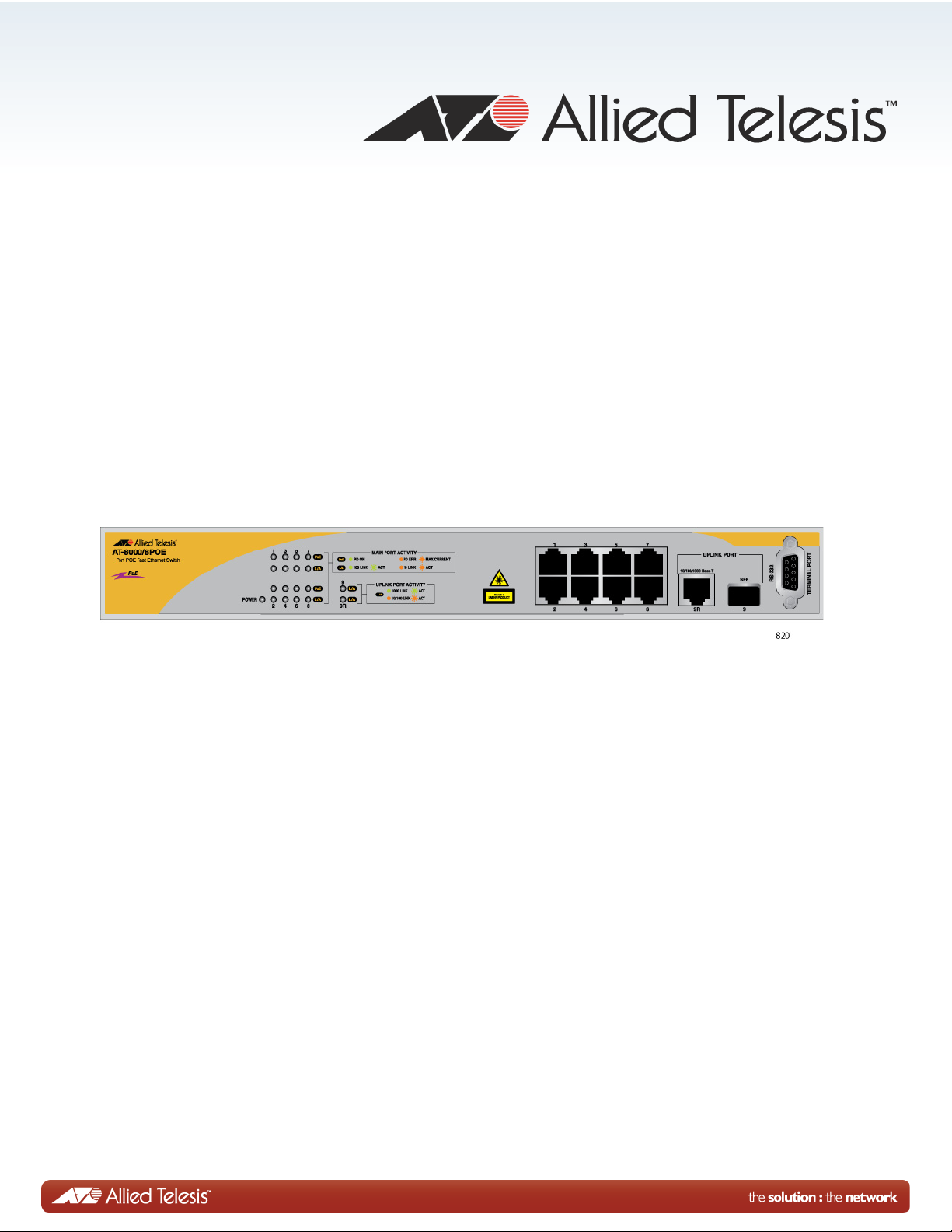
AT-8000/8POE
Layer 2 Fast Ethernet Switch
AT-8000/8POE Layer 2 Fast Ethernet Switch User Guide
AT-S81 Version 1.3.0 (V1.1.1.90)
613-001675 Rev.A
Page 2

Copyright © 2012 Allied Telesis, Inc.
All rights reserved. No part of this publication may be reproduced without prior written permission from Allied Telesis, Inc.
Allied Telesis and the Allied Telesis logo are trademarks of Allied Telesis, Incorporated. All other product names, company names,
logos or other designations mentioned herein are trademarks or registered trademarks of their respective owners.
Allied Telesis, Inc. reserves the right to make changes in specifications and other information contained in this document without prior
written notice. The information provided herein is subject to change without notice. In no event shall Allied Telesis, Inc. be liable for
any incidental, special, indirect, or consequential damages whatsoever, including but not limited to lost profits, arising out of or related
to this manual or the information contained herein, even if Allied Telesis, Inc. has been advised of, known, or should have known, the
possibility of such damages.
Page 3

Contents
Safety Symbols................................................................................................................................................. 14
Contacting Allied Telesis .................................................................................................................................. 15
Section I: Chapter 1: Overview ................................................................................................................ 19
Management Overview..................................................................................................................................... 20
Local Connection.............................................................................................................................................. 21
Remote Connection.......................................................................................................................................... 22
Using an SNMP Network Management Application................................................................................... 22
Management Access Level .............................................................................................................................. 23
Chapter 2: Getting Started with the Menus Interface ................................................................................. 25
Starting a Local Management Session............................................................................................................. 26
Using the Menus Interface................................................................................................................................ 28
Quitting from a Local Management Session..................................................................................................... 29
Chapter 3: Basic Switch Parameters ........................................................................................................... 31
Configuring the IP Address, Subnet Mask, and Gateway Address .................................................................. 32
Enabling and Disabling the DHCP Client ......................................................................................................... 35
Configuring System Administration Information ............................................................................................... 36
Setting the User Interface Configuration .......................................................................................................... 38
Disabling or Enabling the Web Server.............................................................................................................. 42
Disabling or Enabling the Telnet Server ........................................................................................................... 43
Configuring SNTP............................................................................................................................................. 44
Viewing Switch Information .............................................................................................................................. 47
Hardware Information Section ............................................................................................................. 48
Administration Information Section...................................................................................................... 48
System Address Information Section .................................................................................................. 48
Automatic Network Features Section .................................................................................................. 49
Rebooting the Switch........................................................................................................................................ 50
Pinging a Remote System ................................................................................................................................ 52
Working with the System Log ........................................................................................................................... 55
Viewing the System Log............................................................................................................................. 55
Sending the System Log to a Remote Server............................................................................................ 57
Returning the AT-S81 Management Software to the Factory Default Values .................................................. 59
Chapter 4: Port Configuration ...................................................................................................................... 61
Displaying the Port Parameters........................................................................................................................ 62
Enabling and Disabling a Port .......................................................................................................................... 64
Setting a Port’s Speed and Duplex Mode......................................................................................................... 65
Changing the Flow Control Setting................................................................................................................... 67
Displaying Port Statistics .................................................................................................................................. 68
Chapter 5: SNMP ........................................................................................................................................... 71
SNMP Overview ............................................................................................................................................... 72
Default SNMP Community Strings ............................................................................................................. 73
Enabling or Disabling the SNMP Agent............................................................................................................ 74
3
Page 4

Contents
Enabling Authentication Traps .......................................................................................................................... 75
Changing the Default SNMP Community Names ............................................................................................. 76
Working with Trap Receivers ............................................................................................................................77
Adding a Trap Receiver..............................................................................................................................77
Enabling or Disabling Trap Receivers ........................................................................................................77
Modifying a Trap Receiver.......................................................................................................................... 78
Deleting a Trap Receiver............................................................................................................................79
Chapter 6: Port Trunking ............................................................................................................................... 81
Port Trunking Overview .................................................................................................................................... 82
Static Port Trunk Overview.........................................................................................................................82
Port Trunking Guidelines ............................................................................................................................ 83
LACP Trunks..................................................................................................................................................... 84
LACP Trunk Status..................................................................................................................................... 84
LACP Port Priority Parameter..................................................................................................................... 84
LACP Trunk Guidelines ..............................................................................................................................85
Setting Up a Port Trunk ....................................................................................................................................87
Creating a Port Trunk ................................................................................................................................. 87
Modifying a Port Trunk ............................................................................................................................... 89
Enabling or Disabling a Port Trunk............................................................................................................. 90
Setting Up an LACP Trunk................................................................................................................................92
Creating an LACP Trunk ............................................................................................................................ 92
Configuring the LACP Port Priority ............................................................................................................. 93
Viewing the LACP Group Settings..............................................................................................................94
Disabling an LACP Trunk ........................................................................................................................... 95
Chapter 7: Port Mirroring .............................................................................................................................. 97
Port Mirroring Overview ....................................................................................................................................98
Configuring Port Mirroring ................................................................................................................................. 99
Enabling or Disabling Port Mirroring ...............................................................................................................101
Chapter 8: Power Over Ethernet ................................................................................................................. 103
PoE Overview ................................................................................................................................................. 104
Power Budgeting ...................................................................................................................................... 104
Port Prioritization for Power Allocation ..................................................................................................... 105
PoE Device Classes .................................................................................................................................105
Configuring PoE..............................................................................................................................................107
Displaying the PoE Configuration............................................................................................................. 107
Changing the PoE Port’s Admin Setting................................................................................................... 108
Setting the PoE Port’s Priority ..................................................................................................................109
Chapter 9: Virtual LANs and GVRP ............................................................................................................111
VLAN Features ............................................................................................................................................... 112
Increased Performance ............................................................................................................................ 112
Improved Manageability ........................................................................................................................... 112
Increased Security.................................................................................................................................... 112
VLAN Overview...............................................................................................................................................114
VLAN Name.............................................................................................................................................. 114
VLAN Identifier .........................................................................................................................................114
Port VLAN Identifier.................................................................................................................................. 114
VLAN Port Members................................................................................................................................. 114
Tagged Port Members .......................................................................................................................115
Untagged Port Members .................................................................................................................... 115
Incoming and Outgoing Tagged and Untagged Frames .......................................................................... 115
Incoming Frames ............................................................................................................................... 115
Outgoing Frames ............................................................................................................................... 116
Guidelines for Creating a VLAN ............................................................................................................... 116
4
Page 5

AT-S81 Management Software User’s Guide
Untagged VLAN ....................................................................................................................................... 117
Tagged VLAN Example............................................................................................................................ 119
Working with VLANS ...................................................................................................................................... 121
Creating a VLAN ...................................................................................................................................... 121
Configuring the Port PVID........................................................................................................................ 124
Restricting Management VLAN Access ................................................................................................... 125
Displaying the VLANs .............................................................................................................................. 126
Modifying a VLAN .................................................................................................................................... 128
Changing the VLAN Name ................................................................................................................ 128
Adding or Removing a Tagged Port in a VLAN ................................................................................. 128
Deleting a VLAN....................................................................................................................................... 129
Resetting to the Default VLAN ................................................................................................................. 130
GVRP ............................................................................................................................................................. 131
GVRP Overview ....................................................................................................................................... 131
Guidelines ................................................................................................................................................ 131
Enabling or Disabling GVRP .................................................................................................................... 132
Chapter 10: Quality of Service (QoS) ......................................................................................................... 133
QoS Overview ................................................................................................................................................ 134
Mapping CoS Priorities to Egress Queues ..................................................................................................... 137
Configuring CoS ............................................................................................................................................. 140
Chapter 11: IGMP Snooping ....................................................................................................................... 145
IGMP Snooping Overview .............................................................................................................................. 146
Configuring IGMP ........................................................................................................................................... 148
Viewing the Multicast Groups ......................................................................................................................... 150
Chapter 12: Rapid Spanning Tree Protocol (RSTP) ................................................................................. 153
RSTP Overview .............................................................................................................................................. 154
Bridge Priority and the Root Bridge.......................................................................................................... 154
Designated Bridge and Designated Port ........................................................................................... 155
Path Costs and Port Costs ................................................................................................................ 155
Port Priority........................................................................................................................................ 156
Hello Time and Bridge Protocol Data Units (BPDUs) ........................................................................ 157
Point-to-Point and Edge Ports ........................................................................................................... 158
Mixed STP and RSTP Networks .............................................................................................................. 159
Rapid Spanning Tree and VLANs ............................................................................................................ 160
Enabling or Disabling RSTP ........................................................................................................................... 161
Configuring the RSTP Bridge Settings ........................................................................................................... 164
Configuring STP Compatibility........................................................................................................................ 166
Configuring RSTP Port Settings ..................................................................................................................... 167
Configuring the Basic RSTP Port Settings............................................................................................... 167
Configuring the Advanced RSTP Port Settings........................................................................................ 169
Displaying the RSTP Topology....................................................................................................................... 172
Chapter 13: 802.1x Network Access Control ............................................................................................ 175
802.1x Network Access Control Overview ..................................................................................................... 176
Authentication Process ............................................................................................................................ 177
Authenticator Ports................................................................................................................................... 177
General Steps .......................................................................................................................................... 180
Network Access Control Guidelines......................................................................................................... 180
Configuring 802.1x Network Access Control .................................................................................................. 183
Chapter 14: RADIUS Authentication Protocol
.......................................................................................... 189
RADIUS Overview .......................................................................................................................................... 190
RADIUS Implementation Guidelines ........................................................................................................ 190
Configuring the RADIUS Server ..................................................................................................................... 192
5
Page 6

Contents
Displaying the RADIUS Server Settings .........................................................................................................194
Chapter 15: Broadcast Storm Control ........................................................................................................ 195
Broadcast Storm Control Overview................................................................................................................. 196
Configuring Broadcast Storm Control .............................................................................................................197
Chapter 16: MAC Address Tables ..............................................................................................................199
MAC Address Overview .................................................................................................................................. 200
Displaying the MAC Address Tables .............................................................................................................. 202
Displaying the MAC Addresses by Port Number...................................................................................... 202
Displaying the MAC Addresses by MAC .................................................................................................. 203
Displaying the MAC Addresses by VLAN ID ............................................................................................ 204
Setting the Age-Out Time ............................................................................................................................... 206
Chapter 17: Working With System Files .................................................................................................... 207
Downloading a New Management Software Image Using TFTP.................................................................... 208
Uploading or Downloading the Configuration File...........................................................................................211
Uploading the Configuration File ..............................................................................................................211
Downloading a Configuration File.............................................................................................................213
Section II: Chapter 18: Starting a Web Browser Management Session ............................................217
Establishing a Remote Connection to Use the Web Browser Interface ..........................................................218
Web Browser Tools.........................................................................................................................................221
Quitting a Web Browser Management Session .............................................................................................. 222
Chapter 19: Basic Switch Parameters ....................................................................................................... 223
Configuring an IP Address, Subnet Mask and Gateway Address...................................................................224
Enabling and Disabling the DHCP Client ........................................................................................................226
Configuring System Administration Information ..............................................................................................227
Setting the User Interface Configuration.........................................................................................................229
Enabling or Disabling the Web Server ............................................................................................................ 232
Enabling or Disabling the Telnet Server ......................................................................................................... 233
Configuring SNTP ........................................................................................................................................... 234
Viewing System Information ...........................................................................................................................235
Hardware Information Section:........................................................................................................... 236
Administration Information Section: ................................................................................................... 236
System MAC Address, IP Address, Subnet Mask, and Gateway Section: ........................................236
Rebooting a Switch ......................................................................................................................................... 238
Pinging a Remote System .............................................................................................................................. 239
Working with the System Log .........................................................................................................................241
Viewing the System Log ........................................................................................................................... 241
Sending the System Log to a Remote Server .......................................................................................... 243
Returning the AT-S81 Management Software to the Factory Default Values................................................. 244
Chapter 20: Port Configuration ................................................................................................................... 245
Viewing and Configuring Multiple Ports ..........................................................................................................246
Viewing and Configuring a Single Port ...........................................................................................................249
Displaying Port Statistics ................................................................................................................................252
Chapter 21: SNMP ........................................................................................................................................ 255
Enabling or Disabling the SNMP Agent .......................................................................................................... 256
Changing the Default SNMP Community Names ........................................................................................... 257
Working with Trap Receivers ..........................................................................................................................258
Adding and Enabling a Trap Receiver...................................................................................................... 258
Disabling a Trap Receiver ........................................................................................................................258
Deleting a Trap Receiver..........................................................................................................................258
Restoring the Trap Receivers................................................................................................................... 258
6
Page 7

AT-S81 Management Software User’s Guide
Chapter 22: Port Trunking .......................................................................................................................... 261
Setting Up a Port Trunk .................................................................................................................................. 262
Creating a Port Trunk............................................................................................................................... 262
Modifying a Port Trunk ............................................................................................................................. 263
Enabling or Disabling a Port Trunk .......................................................................................................... 264
Setting Up an LACP Trunk ............................................................................................................................. 265
Creating an LACP Trunk.......................................................................................................................... 265
Configuring the LACP Port Priority........................................................................................................... 266
Viewing the LACP Group Settings ........................................................................................................... 267
Disabling an LACP Trunk......................................................................................................................... 267
Chapter 23: Port Mirroring .......................................................................................................................... 269
Configuring Port Mirroring .............................................................................................................................. 270
Disabling Port Mirroring .................................................................................................................................. 271
Chapter 24: Power Over Ethernet .............................................................................................................. 273
Configuring PoE ............................................................................................................................................. 274
Changing the PoE Port’s Admin Setting .................................................................................................. 275
Setting the PoE Port’s Priority.................................................................................................................. 275
Chapter 25: Virtual LANs ............................................................................................................................ 277
Creating a VLAN............................................................................................................................................. 278
Configuring the PVID of Untagged Ports ........................................................................................................ 280
Displaying the VLANs..................................................................................................................................... 282
Restricting Management VLAN Access.......................................................................................................... 284
Modifying a VLAN........................................................................................................................................... 285
Deleting a VLAN ............................................................................................................................................. 287
Deleting All VLANs ......................................................................................................................................... 288
Enabling or Disabling GVRP .......................................................................................................................... 289
Chapter 26: Quality of Service (QoS) ......................................................................................................... 291
Mapping CoS Priorities to Egress Queues ..................................................................................................... 292
Configuring CoS ............................................................................................................................................. 293
Chapter 27: IGMP ......................................................................................................................................... 295
Configuring IGMP ........................................................................................................................................... 296
Viewing the Multicast Group Members........................................................................................................... 297
Chapter 28: RSTP ........................................................................................................................................ 299
Enabling or Disabling RSTP and STP Compatibility ...................................................................................... 300
Basic RSTP Configuration.............................................................................................................................. 301
Configuring RSTP Port Settings ..................................................................................................................... 303
Configuring the Basic RSTP Port Settings............................................................................................... 303
Configuring the Advanced RSTP Port Settings........................................................................................ 304
Viewing the RSTP Topology........................................................................................................................... 306
Chapter 29: 802.1x Network Access Control ............................................................................................ 307
Configuring 802.1x Network Access Control .................................................................................................. 308
Chapter 30: RADIUS Authentication Protocol .......................................................................................... 311
Configuring the RADIUS Client ...................................................................................................................... 312
Chapter 31: Broadcast Storm Control ....................................................................................................... 313
Configuring Broadcast Storm Control ............................................................................................................. 314
Chapter 32: MAC Address Tables .............................................................................................................. 315
Displaying the MAC Address Tables .............................................................................................................. 316
Displaying the MAC Addresses by MAC.................................................................................................. 318
Displaying the MAC Addresses by VLAN ID............................................................................................ 319
7
Page 8

Contents
Setting the Aging Time.................................................................................................................................... 321
Chapter 33: Working With System Files .................................................................................................... 323
Downloading a New Management Software Image Using TFTP.................................................................... 324
Uploading or Downloading the Configuration File...........................................................................................326
Section III: Chapter 32: Getting Started with the Command Line Interface ..................................... 331
CLI Command Modes Introduction ................................................................................................................. 332
Command Formatting Conventions.......................................................................................................... 333
User EXEC Command Mode.................................................................................................................... 334
Global Configuration Command Mode ..................................................................................................... 335
Port Mirroring Example ...................................................................................................................... 339
Starting the Command Line Interface .............................................................................................................342
Command Formatting .....................................................................................................................................343
Command Line Interface Features ...........................................................................................................343
Command Line Syntax Conventions ........................................................................................................ 343
Appendix A: AT-8000/POE Default Settings .............................................................................................. 345
Basic Switch Default Settings .........................................................................................................................346
System Reboot Default Settings............................................................................................................... 346
User Interface Configuration Default Settings ..........................................................................................346
Management Interface Default Settings ................................................................................................... 346
Ping Default Settings ................................................................................................................................347
System IP Configuration Default Settings ................................................................................................347
System Administration Configuration Default Settings .............................................................................347
SNMP Default Settings ................................................................................................................................... 348
Port Configuration Default Settings................................................................................................................. 349
Quality of Service ............................................................................................................................................350
IGMP Snooping Default Settings ....................................................................................................................351
RSTP Default Settings .................................................................................................................................... 352
802.1x Network Access Control Default Settings ........................................................................................... 353
RADIUS Server Default Settings ....................................................................................................................354
Broadcast Storm Control Default Settings ......................................................................................................355
Index ..............................................................................................................................................................357
8
Page 9

Figures
Figure 1. Connecting the Management Cable to the Console Port .....................................................................................26
Figure 2. Login Menu...........................................................................................................................................................27
Figure 3. Main Menu............................................................................................................................................................27
Figure 4. Basic Switch Configuration Menu.........................................................................................................................32
Figure 5. System IP Configuration Menu.............................................................................................................................33
Figure 6. System Admin. Configuration Menu.....................................................................................................................36
Figure 7. User Interface Configuration Menu.......................................................................................................................38
Figure 8. SNTP Configuration Menu....................................................................................................................................44
Figure 9. Time Zone Configuration Menu............................................................................................................................45
Figure 10. General Information Menu..................................................................................................................................47
Figure 11. Switch Tools Configuration Menu.......................................................................................................................50
Figure 12. System Reboot Menu.........................................................................................................................................51
Figure 13. Ping Execution Menu .........................................................................................................................................52
Figure 14. Ping Results .......................................................................................................................................................54
Figure 15. System Log Menu ..............................................................................................................................................55
Figure 16. Remote System Log Menu .................................................................................................................................57
Figure 17. Port Configuration Menu.....................................................................................................................................62
Figure 18. Statistics Menu ...................................................................................................................................................68
Figure 19. SNMP Configuration Menu.................................................................................................................................75
Figure 20. Static Port Trunk Example..................................................................................................................................82
Figure 21. Advanced Switch Configuration Menu................................................................................................................87
Figure 22. Trunk Configuration Menu..................................................................................................................................88
Figure 23. LACP Port Priority Menu ....................................................................................................................................93
Figure 24. LACP Group Status Menu..................................................................................................................................95
Figure 25. Port Mirroring Menu............................................................................................................................................99
Figure 26. Power Over Ethernet Menu..............................................................................................................................107
Figure 27. VLAN - Example 2............................................................................................................................................117
Figure 28. Example of a Tagged VLAN.............................................................................................................................119
Figure 29. VLAN Management Menu ................................................................................................................................122
Figure 30. VLAN Creation Menu........................................................................................................................................123
Figure 31. Config VLAN Member Menu.............................................................................................................................127
Figure 32. GVRP Example ................................................................................................................................................131
Figure 33. Quality of Service Configuration Menu .............................................................................................................137
Figure 34. Traffic Class Configuration Menu .....................................................................................................................138
Figure 35. Port Priority Configuration Menu ......................................................................................................................141
Figure 36. IGMP Configuration Menu............................................................................................
Figure 37. MAC Address DIsplayed on IGMP Configuration Menu...................................................................................150
Figure 38. View Group Members Menu.............................................................................................................................151
Figure 39. Point-to-Point Ports ..........................................................................................................................................158
Figure 40. Edge Port .........................................................................................................................................................159
Figure 41. Point-to-Point and Edge Port............................................................................................................................159
Figure 42. VLAN Fragmentation........................................................................................................................................160
Figure 43. RSTP Configuration Menu................................................................................................................................161
Figure 44. RSTP Basic Port Configuration Menu ..............................................................................................................167
Figure 45. RSTP Advanced Port Configuration Menu .......................................................................................................170
Figure 46. Topology Information Menu..............................................................................................................................172
Figure 47. Example of the Authenticator Role ...................................................................................................................178
Figure 48. Authentication Across Multiple Switches ..........................................................................................................182
Figure 49. Port Based Access Control Configuration Menu ..............................................................................................183
Figure 50. RADIUS Server Configuration Menu ................................................................................................................192
....................................148
9
Page 10

Figures
Figure 51. Storm Control Configuration Menu ...................................................................................................................197
Figure 52. MAC Address Table Menu................................................................................................................................202
Figure 53. Display MAC Addresses by Port Menu.............................................................................................................203
Figure 54. Display MAC Addresses by Port Menu.............................................................................................................204
Figure 55. Display MAC Addresses by VLAN ID Menu .....................................................................................................205
Figure 56. Software Upgrade Menu (1 of 2) ......................................................................................................................209
Figure 57. Software Upgrade Menu (2 of 2) ......................................................................................................................209
Figure 58. Configuration File Upload/Download Menu ......................................................................................................212
Figure 59. TFTP Configuration File Upload/Download Menu ............................................................................................212
Figure 60. Entering a Switch’s IP Address in the URL Field..............................................................................................218
Figure 61. AT-S81 Login Dialog Box .................................................................................................................................219
Figure 62. Home Page for the AT-8000/8POE ..................................................................................................................219
Figure 63. IP Configuration Page.......................................................................................................................................224
Figure 64. Administration Configuration Page ...................................................................................................................227
Figure 65. User Interface Page..........................................................................................................................................229
Figure 66. SNTP Configuration Page ................................................................................................................................234
Figure 67. Switch Information Page...................................................................................................................................235
Figure 68. System Reboot Configuration Page .................................................................................................................238
Figure 69. Ping Test Configuration Page...........................................................................................................................239
Figure 70. Ping Test Results Page ....................................................................................................................................240
Figure 71. System Log Page .............................................................................................................................................241
Figure 72. Remote System Log Page................................................................................................................................243
Figure 73. Port Configuration Page ...................................................................................................................................246
Figure 74. Configuration of Port Page ...............................................................................................................................249
Figure 75. Statistics Page..................................................................................................................................................252
Figure 76. SNMP Configuration Page................................................................................................................................257
Figure 77. Trunk Configuration Page.................................................................................................................................262
Figure 78. LACP Port Priority Page ...................................................................................................................................266
Figure 79. LACP Group Status Page.................................................................................................................................267
Figure 80. Port Mirroring Page...........................................................................................................................................270
Figure 81. Power Over Ethernet Configuration Page ........................................................................................................274
Figure 82. Create VLAN Page ...........................................................................................................................................278
Figure 83. PVID Page........................................................................................................................................................280
Figure 84. VLAN Information Page ....................................................................................................................................282
Figure 85. VLAN Configuration - Members Page ..............................................................................................................283
Figure 86. Modify VLAN Page ...........................................................................................................................................286
Figure 87. Traffic Class Configuration Page......................................................................................................................292
Figure 88. Port Priority Configuration Page .......................................................................................................................293
Figure 89. IGMP Snooping Page.......................................................................................................................................296
Figure 90. IGMP Snooping - Group Members Page..........................................................................................................297
Figure 91. Rapid Spanning Tree Configuration Page ........................................................................................................300
Figure 92. RSTP Basic Port Configuration Page ...............................................................................................................303
Figure 93. RSTP Advanced Port Configuration Page........................................................................................................304
Figure 94. Designated Topology Information Page ...........................................................................................................306
Figure 95. 802.1x Configuration Page ...............................................................................................................................308
Figure 96. RADIUS Configuration Page ............................................................................................................................312
Figure 97. Broadcast Storm Control Page.........................................................................................................................314
Figure 98. MAC Address by Port Page..............................................................................................................................316
Figure 99. MAC Address Table by Port Page....................................................................................................................317
Figure 100. MAC Address by MAC Page ..........................................................................................................................318
Figure 101. MAC Addresses by VLAN Page .....................................................................................................................319
Figure 102. MAC Addresses by VLAN Page .....................................................................................................................320
Figure 103. Image Upgrade Page......................................................................................................................................325
Figure 104. Configuration File Upload/Download Page.....................................................................................................327
Figure 105. Main Menu......................................................................................................................................................342
Figure 106. Command Line Prompt, User Executive Mode...............................................................................................342
10
Page 11

Tables
Table 1. Menus Interface Operations .................................................................................................................................28
Table 2. Power Classes for Powered Devices ..................................................................................................................105
Table 3. Port Numbers for VLAN Example 2 ....................................................................................................................117
Table 4. Ports for Tagged VLAN Example ........................................................................................................................119
Table 5. Default Mappings of IEEE 802.1p Priority Levels to Egress Port Priority Queues .............................................135
Table 6. RSTP Auto-Detect Port Costs ............................................................................................................................156
Table 7. RSTP Auto-Detect Port Trunk Costs ..................................................................................................................156
Table 8. Port Priority Value Increments ............................................................................................................................157
Table 9. RSTP Point-to-Point Status ................................................................................................................................171
Table 10. RSTP Point-to-Point Status ..............................................................................................................................304
Table 11. Command Modes .............................................................................................................................................333
Table 12. User EXEC Command Mode Commands ........................................................................................................334
Table 13. Privileged EXEC Command Mode Commands ................................................................................................335
Table 14. Global Configuration Command Mode Commands ..........................................................................................336
Table 15. Interface Configuration Command Mode Commands ......................................................................................338
Table 16. VLAN Configuration Command Mode Commands ...........................................................................................340
Table 17. Command Line Syntax Conventions ................................................................................................................343
11
Page 12

Tables
12
Page 13

Preface
This guide contains instructions on how to use the AT-S81 management
software to manage and monitor the AT-8000/8POE Layer 2 Fast Ethernet
Switch.
The AT-S81 management software has three management interfaces:
menus, web browser, and CLI. You access the menus and CLI interfaces
through the console port on the switch or through Telnet, and the web
browser interface from any management workstation on your network that
has a web browser application. For background information on the
management interfaces, refer to Chapter 1, “Overview” on page 19.
This preface contains the following sections:
“Safety Symbols” on page 14
“Contacting Allied Telesis” on page 15
13
Page 14
Preface
Note
Caution
Warning
Warning
Safety Symbols
This document uses the following conventions:
Notes provide additional information.
Cautions inform you that performing or omitting a specific action
may result in equipment damage or loss of data.
Warnings inform you that performing or omitting a specific action
may result in bodily injury.
Warnings inform you that an eye and skin hazard exists due to the
presence of a Class 1 laser device.
14
Page 15

Contacting Allied Telesis
If you need assistance with this product, you may contact Allied Telesis
technical support by going to the Support & Services section of the Allied
Telesis web site at www.alliedtelesis.com/support. You can find links for
the following services on this page:
24/7 Online Support - Enter our interactive support
center to search for answers to your questions in our
knowledge database, check support tickets, learn
about RMAs, and contact Allied Telesis technical
experts.
USA and EMEA phone support - Select the phone
number that best fits your location and customer type.
Hardware warranty information - Learn about Allied
Telesis warranties and register your product online.
Replacement Services - Submit a Return Merchandise
Authorization (RMA) request via our interactive support
center.
AT-8000/8POE Layer 2 Fast Ethernet Switch User Guide
Documentation - View the most recent installation
guides, user guides, software release notes, white
papers and data sheets for your product.
Software Updates - Download the latest software
releases for your product.
For sales or corporate contact information, go to
www.alliedtelesis.com/purchase and select your region.
15
Page 16

Preface
16
Page 17

Section I
Note
Using the Menus Interface
The chapters in this section explain how to manage the switch using the
menus interface of the AT-S81 management software. The chapters
include:
Chapter 1, “Overview” on page 19
Chapter 2, “Getting Started with the Menus Interface” on page 25
Chapter 3, “Basic Switch Parameters” on page 31
Chapter 4, “Port Configuration” on page 61
Chapter 5, “SNMP” on page 71
Chapter 6, “Port Trunking” on page 81
Chapter 7, “Port Mirroring” on page 97
Chapter 8, “Power Over Ethernet” on page 103
Chapter 9, “Virtual LANs and GVRP” on page 111
Chapter 10, “Quality of Service (QoS)” on page 133
Chapter 11, “IGMP Snooping” on page 145
Chapter 12, “Rapid Spanning Tree Protocol (RSTP)” on page 153
Chapter 13, “802.1x Network Access Control” on page 175
Chapter 14, “RADIUS Authentication Protocol” on page 189
Chapter 15, “Broadcast Storm Control” on page 195
Chapter 16, “MAC Address Tables” on page 199
Chapter 17, “Working With System Files” on page 207
The web browser interface is described in Section II, “Using the Web
Browser Interface” on page 215, and the command line interface is
described in Section III, “Using the Command Line Interface” on
page 329.
Section I: Using the Menus Interface 17
Page 18

18 Section I: Using the Menus Interface
Page 19

Chapter 1
Overview
This chapter provides an overview of the AT-S81 management software
for the AT-8000/8POE Fast Ethernet switch. This chapter describes the
different methods for accessing the software and the management access
levels. This chapter contains the following sections:
“Management Overview” on page 20
“Local Connection” on page 21
“Remote Connection” on page 22
“Management Access Level” on page 23
19
Page 20

Chapter 1: Overview
Note
Management Overview
The AT-S81 management software allows you to view and adjust the
operating parameters of the AT-8000/8POE Fast Ethernet switch. Here
are a few examples of the functions that you can perform with the
management software:
Enable and disable ports
Configure a port’s speed and duplex mode
Create port trunks
Configure a port mirror
Configure Quality of Service (QoS)
Create and tagged virtual LANs
Configure 802.1x network access control
The AT-S81 management software is preinstalled on the switch with
default settings for all of the switch’s operating parameters. You do not
have to manage the switch if the default settings are adequate for your
network. Instead, you can use the device as an unmanaged switch by
connecting it to your network, as explained in the hardware installation
guide, and powering on the unit.
The default settings for the management software are listed in
Appendix A, “AT-8000/POE Default Settings” on page 345.
To actively manage the switch and adjust its operating parameters, you
must connect to an AT-8000/8POE Fast Ethernet switch and access the
switch’s AT-S81 management software. There are two ways to connect to
the switch:
Locally
Remotely
Depending upon the method you choose, specific AT-S81 software
interfaces are available. When you have a local connection, you can use
the menus (described in Section I of this guide) or the command line
interface (CLI) (described in Section III). With a remote connection you
can use the menus, CLI, and web browser interfaces, or a third-party
network management application. (The web browser interface is
described in Section II).
The following sections in this chapter briefly describe each type of
management session.
20
Page 21

Local Connection
Note
AT-S81 Management Software User’s Guide
To establish a local connection with a switch, you connect a terminal or a
PC with a terminal emulator program to the terminal port on the front of the
switch using the management cable included with the unit. This type of
connection is referred to as “local” because you must be physically close
to the switch, such as in the wiring closet where the switch is located.
For instructions on how to start a local management session, refer to
“Starting a Local Management Session” on page 26.
With a local connection, you can manage the switch using the menus or
CLI.
A switch does not need an Internet Protocol (IP) address for you to
manage it locally. You can start a local management session on a switch
at any time. It does not interfere with the forwarding of network packets by
the device.
21
Page 22

Chapter 1: Overview
Note
Remote Connection
You can use any management station on your network that has the Telnet
application to manage an AT-8000/8POE Fast Ethernet switch. This is
referred to as a remote connection. A remote connection allows you to use
any of the AT-S81 software user interfaces: menus, CLI, web browser, or
SNMP.
In order for you to manage a switch using the web browser interface, the
switch must have an IP address and subnet mask. To manually assign an
IP address, refer to “Configuring the IP Address, Subnet Mask, and
Gateway Address” on page 32. To configure the switch to obtain its IP
configuration from a DHCP server, refer to “Enabling and Disabling the
DHCP Client” on page 35. The initial assignment of an IP address must be
made through a local management session.
For instructions on how to start a remote management session to use the
web browser interface, refer to “Establishing a Remote Connection to Use
the Web Browser Interface” on page 218.
Using an SNMP
Network
Management
Application
In order to remotely manage a switch using a web browser, the
remote management station must be a member of the switch’s
Default VLAN. The switch processes remote management packets
only when they are received on an untagged port of the Default
VLAN.
You can use the Simple Network Management Protocol (SNMP) to run a
network management application such as AT-View to manage the switch
through a remote connection. A familiarity with how to use management
information base (MIB) objects is necessary for this type of management.
The AT-S81 management software supports the following MIBs:
SNMP MIB-II (RFC 1213)
Bridge MIB (RFC 1493)
Remote Network MIB (RFC 1757)
Allied Telesis managed switch MIB
You must download the Allied Telesis managed switch MIB (atiswitch.mib)
file from the Allied Telesis web site and compile the files with your SNMP
application. For compilation instructions, refer to your third-party
application’s documentation. Refer to Chapter 5, “SNMP” on page 71 for
information about how to configure SNMP on the switch.
22
Page 23

Management Access Level
The AT-S81 management software has one level of management access:
manager. When you log in as a manager, you can view and configure all of
a switch’s operating parameters. You log in as a manager by entering the
appropriate username and password when you start an AT-S81
management session. The default username is “manager” and the default
password is “friend”.
AT-S81 Management Software User’s Guide
23
Page 24

Chapter 1: Overview
24
Page 25

Chapter 2
Getting Started with the Menus Interface
This chapter provides information and instructions on how to access the
menus interface of the AT-S81 management software by starting a local
management session. This chapter contains the following sections:
“Starting a Local Management Session” on page 26
“Using the Menus Interface” on page 28
“Quitting from a Local Management Session” on page 29
Section I: Using the Menus Interface 25
Page 26
Chapter 2: Getting Started with the Menus Interface
Note
Note
Starting a Local Management Session
You establish a local management session with the AT-8000/8POE switch
by connecting a terminal or personal computer with a terminal emulation
program to the RS-232 console port on the front panel of the switch.
You do not need to assign an IP address to the switch to manage
the unit from a local management session.
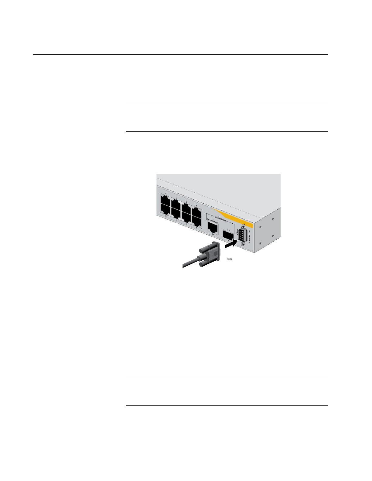
To start a local management session, perform the following procedure:
1. Connect one end of the management cable included with the switch to
the console port on the AT-8000/8POE switch, as shown in Figure 1.
Figure 1. Connecting the Management Cable to the Console Port
2. Connect the other end of the cable to the RS-232 port on a terminal or
PC with a terminal emulator program.
3. Configure the terminal or terminal emulator program as follows:
Baud per second: 9600
Data bits: 8
Stop bits: 1
Flow control: None
These settings are for a DEC VT100 or ANSI terminal, or an
equivalent terminal emulation program. You cannot change this.
26 Section I: Using the Menus Interface
Page 27

AT-S81 Management Software User’s Guide
Note
==============================================================
AT-8000/8POE Management System
Local - Console
Allied Telesis International Corp.
Copyright 2007
==============================================================
Login Menu
Login:
AT-8000/8POE Local Management System
Main Menu
[G]eneral Information
[B]asic Switch Configuration
[A]dvanced Switch Configuration
Switch [T]ools
[S]tatistics
[C]ommand Line Interface
[Q]uit
Command>
The Login Menu is shown in Figure 2.
Figure 2. Login Menu
4. Enter the manager login name and press Return. The default name is
“manager”.
You are prompted for a password.
5. Enter the manager password. The default password is “friend”.
To change the login name or password, refer to “Setting the User
Interface Configuration” on page 38.
The Main Menu is shown in Figure 3.
Section I: Using the Menus Interface 27
Figure 3. Main Menu
Page 28

Chapter 2: Getting Started with the Menus Interface
Note
Using the Menus Interface
If you are using a DEC VT00 or ANSI (the default) terminal configuration,
refer to Table 1 for instructions on how to move through the menus and
select menu options.
When directed to You must
Make a menu selection Type the menu option letter enclosed
Table 1. Menus Interface Operations
in brackets, such as typing P to select
[P]ort Configuration.
Enter information (for
example, entering a port
number)
Return to previous menu Type Q for Quit to previous menu.
When you enter a letter to select a field in which you can enter a value, a
message is displayed. For example:
Enter new password>
The “>” symbol indicates that you can enter a new value for the parameter
or change the existing value. After you have entered a value, press Enter.
Changes are immediately activated on the AT-8000/8POE switch.
The web browser interface is described in Section II, “Using the Web
Browser Interface” on page 215, and the command line interface is
described in Section III, “Using the Command Line Interface” on
page 329.
Enter the information.
28 Section I: Using the Menus Interface
Page 29

Quitting from a Local Management Session
Note
To quit a local management session, return to the Main Menu and type Q
for Quit. When you are finished managing the switch, make sure to exit
from a management session. Quitting from a local session prevents
unauthorized changes to the switch’s configuration if you leave your
workstation unattended.
A local management session automatically times out if there is no
management activity during a pre-defined length of time referred to
as the timeout period. The timeout feature is intended to protect the
parameter settings on the switch from unauthorized changes should
you leave your management station unattended during a
management session. The default timeout value is 10 minutes. To
change the timeout default value, refer to “Setting the User Interface
Configuration” on page 38.
AT-S81 Management Software User’s Guide
Section I: Using the Menus Interface 29
Page 30

Chapter 2: Getting Started with the Menus Interface
30 Section I: Using the Menus Interface
Page 31

Chapter 3
Basic Switch Parameters
This chapter contains the following sections:
“Configuring the IP Address, Subnet Mask, and Gateway Address” on
page 32
“Enabling and Disabling the DHCP Client” on page 35
“Configuring System Administration Information” on page 36
“Setting the User Interface Configuration” on page 38
“Disabling or Enabling the Web Server” on page 42
“Disabling or Enabling the Telnet Server” on page 43
“Viewing Switch Information” on page 47
“Rebooting the Switch” on page 50
“Pinging a Remote System” on page 52
“Working with the System Log” on page 55
“Returning the AT-S81 Management Software to the Factory Default
Values” on page 59
Section I: Using the Menus Interface 31
Page 32

Chapter 3: Basic Switch Parameters
AT-8000/8POE Local Management System
Main Menu -> Basic Switch Configuration Menu
System [A]dministration Configuration
System [I]P Configuration
S[N]MP Configuration
[P]ort Configuration
[U]ser Interface Configuration
[M]AC Address Table Menu ...
Rapid [S]panning Tree Configuration
Storm [C]ontrol Configuration
SN[T}P Configuration
[Q]uit to previous menu
Command>
Configuring the IP Address, Subnet Mask, and Gateway Address
This procedure explains how to manually assign an IP address, subnet
mask, and gateway address to the switch. Before performing the
procedure, note the following:
An IP address and subnet mask are not required for normal network
operations of the switch. Values for these parameters are only required
if you want to remotely manage the device with a web browser.
A gateway address is only required if you want to remotely manage
the device from a remote management station that is separated from
the switch by a router.
To configure the switch to automatically obtain its IP configuration from
a DHCP server on your network, go to “Enabling and Disabling the
DHCP Client” on page 35.
To set the switch’s IP configuration, perform the following procedure:
1. From the Main Menu, type B to select Basic Switch Configuration.
The Basic Switch Configuration Menu is shown in Figure 4.
Figure 4. Basic Switch Configuration Menu
32 Section I: Using the Menus Interface
Page 33

AT-S81 Management Software User’s Guide
AT-8000/8POE Local Management System
Basic Switch Configuration -> System IP Configuration Menu
MAC Address: 00:06:5H:B2:65:84
IP Address: 0.0.0.0
Subnet Mask: 0.0.0.0
Gateway: 0.0.0.0
DHCP Mode: Disabled
----------------------- <COMMAND> ----------------------------Set [I]P Address
Set Subnet [M]ask
Set Default [G]ateway
Enable/Disable [D]HCP Mode
[Q]uit to previous menu
Command>
2. From the Basic Switch Configuration Menu, type I to select System IP
Configuration.
The System IP Configuration Menu is shown in Figure 5.
Figure 5. System IP Configuration Menu
The top portion of the menu displays the current IP address, subnet
mask, and gateway address for the switch. The menu also displays the
switch’s MAC address. The MAC address cannot be changed. The
menu also displays the current status of the DHCP client on the switch.
The Enable/Disable DHCP Mode option is described in “Enabling and
Disabling the DHCP Client” on page 35.
3. To set the switch’s IP address, do the following:
a. Type I to select Set IP Address.
4. To set the switch’s subnet mask, do the following:
The following prompt is displayed:
Enter new IP address>
b. Enter the IP address for the switch.
a. Type M to select Set Subnet Mask.
Section I: Using the Menus Interface 33
The following prompt is displayed:
Enter new subnet mask>
Page 34

Chapter 3: Basic Switch Parameters
b. Enter the subnet mask for the switch.
5. To set the switch’s gateway address, do the following:
a. Type G to select Set Default Gateway.
The following prompt is displayed:
Enter new gateway IP address>
b. Enter the gateway IP address for the switch.
34 Section I: Using the Menus Interface
Page 35

Enabling and Disabling the DHCP Client
This procedure explains how to activate and deactivate the DHCP client
on the switch. When the client is activated, the switch obtains its IP
configuration, such as its IP address and subnet mask, from a DHCP
server on your network. Before performing the procedure, note the
following:
An IP address and subnet mask are not required for normal network
operations of the switch. Values for these parameters are only required
if you want to remotely manage the device with a web browser.
The DHCP client is disabled by default on the switch.
The DHCP client does not support BOOTP servers.
To activate or deactivate the DHCP client on the switch, perform the
following procedure:
1. From the Main Menu, type B to select Basic Switch Configuration.
AT-S81 Management Software User’s Guide
The Basic Switch Configuration Menu is shown in Figure 4 on page 32.
2. From the Basic Switch Configuration Menu, type I to select System IP
Configuration.
The System IP Configuration Menu is shown in Figure 5 on page 33.
3. Type D to select Enable/Disable DHCP Mode.
The following prompt is displayed:
Enable or Disable DHCP mode (E/D)>
4. Type E to select Enable or D to select Disable.
If you enable the client, it immediately begins to send queries to the
DHCP server. It continues to send queries until it receives a response.
Section I: Using the Menus Interface 35
Page 36

Chapter 3: Basic Switch Parameters
AT-8000/8POE Local Management System
Basic Switch Configuration -> System Admin. Configuration Menu
Description: AT-8000/8POE
ObjectID: 1.3.6.1.4.1.207.1.4
Name:
Location:
Contact:
----------------------- <COMMAND> ----------------------------Set System [N]ame
Set System [L]ocation
Set System [C]ontact Information
[Q]uit to previous menu
Command>
Configuring System Administration Information
This section explains how to assign a name to the switch, as well as
specify the location of the switch and the name of the switch’s
administrator. Entering this information is optional.
To set a switch’s administration information, perform the following
procedure:
1. From the Main Menu, type B to select Basic Switch Configuration.
The Basic Switch Configuration Menu is shown in Figure 4 on page 32.
2. From the Basic Switch Configuration Menu, type A to select System
Administration Information.
The System Administration Configuration Menu is shown in Figure 6.
Figure 6. System Admin. Configuration Menu
The Description parameter in the top portion of the menu displays the
model name of the switch. The System Object ID parameter is the
numeric ID of the switch. You cannot change these parameters.
3. To set the system’s name, do the following:
a. Type N to select Set System Name.
The following prompt is displayed:
36 Section I: Using the Menus Interface
Enter system name>
Page 37

AT-S81 Management Software User’s Guide
Note
b. Type a name for the switch (for example, Sales). The name is
optional and can contain up to 50 characters.
Allied Telesis recommends that you assign names to the switches.
Names can help you identify the switches when you manage them
and can also help you avoid performing a configuration procedure
on the wrong switch.
4. To enter the system’s location, do the following:
a. Type L to select Set System Location.
The following prompt is displayed:
Enter system location>
b. Type information to describe the location of the switch (for
instance, Third Floor). The location is optional and can contain up
to 50 characters.
5. To enter the administrator’s name, do the following:
a. Type C to select Set System Contact Information.
The following prompt is displayed:
Enter system contact>
b. Type the name of the network administrator responsible for
managing the switch. The contact name is optional and can
contain up to 50 characters.
Section I: Using the Menus Interface 37
Page 38

Chapter 3: Basic Switch Parameters
AT-8000/8POE Local Management System
Basic Switch Configuration -> User Interface Configuration Menu
Console UI Idle Timeout: 5 Min.
Telnet UI Idle Timeout: 5 min.
Telnet Server: Enabled
SNMP Agent: Enabled
Web Server: Enabled
User Name: manager
----------------------- <COMMAND> ----------------------------Set [C]onsole UI Time Out Enable/Disable Te[l]net Server
Set [T]elnet UI Time Out Enable/Disable [S]NMP Agent
Change Administrator User [N]ame Enable/Disable [W]eb Server
Change Administrator [P]assword [Q]uit to previous menu
[R]ADIUS Server Configuration
Command>
Setting the User Interface Configuration
This procedure explains how to adjust the user interface and security
features on the switch. With this procedure you can change various
settings that control user access to the switch.
To set the switch’s user interface configuration, perform the following
procedure:
1. From the Main Menu, type B to select Basic Switch Configuration.
The Basic Switch Configuration Menu is shown in Figure 4 on page 32.
2. From the Basic Switch Configuration Menu, type U to select User
Interface Configuration.
The User Interface Configuration Menu is shown in Figure 7.
The Telnet server option is described in “Disabling or Enabling the
Figure 7. User Interface Configuration Menu
Telnet Server” on page 43.
38 Section I: Using the Menus Interface
The web server option is described in “Disabling or Enabling the Web
Server” on page 42.
Page 39

AT-S81 Management Software User’s Guide
Note
The SNMP option is described in “Enabling or Disabling the SNMP
Agent” on page 74.
The RADIUS Server Configuration option is described Chapter 14,
“RADIUS Authentication Protocol” on page 189.
3. To configure the console UI idle time out parameter, do the following:
a. Type C to select Set Console UI Time Out.
The following prompt is displayed:
Enter console idle timeout>
b. Enter a number for the timeout value. The range is 0 to 60 minutes,
and the default is 5 minutes. A timeout value to 0 causes the switch
to never time out a local management session.
The console UI idle time out parameter specifies the length of time
a local management session can be inactive before the
management software automatically ends it. This feature prevents
unauthorized individuals from configuring the switch if you leave
your management workstation unattended.
This parameter applies to a local management session but not to a
remote SNMP or web management session. An SNMP
management session remains active as long as the network
management application is active. A web browser management
session remains active as long as your web browser is open.
If you select 0, you must always remember to properly log off from a
local management session when you are finished to prevent
blocking future management sessions with the switch.
4. To configure the Telnet UI idle time out parameter, do the following:
a. Type T to select Set Telnet UI Time Out.
The following prompt is displayed:
Enter console idle timeout>
b. Enter a number for the timeout value. The range is 0 to 60 minutes,
and the default is 5 minutes. A timeout value to 0 causes the switch
to never timeout a local management session.
Section I: Using the Menus Interface 39
Page 40

Chapter 3: Basic Switch Parameters
The Telnet UI idle time out parameter specifies the length of time a
remote Telnet management session can be inactive before the
management software automatically ends it. This feature prevents
unauthorized individuals from configuring the switch if you leave
your management workstation unattended.
This parameter applies to a local management session but not to a
remote SNMP or web management session. An SNMP
management session remains active as long as the network
management application is active. A web browser management
session remains active as long as your web browser is open.
5. To change the AT-S81 management login user name, do the
following:
a. Type N to select Change Administrator User Name.
The following prompt is displayed:
Enter current password>
b. Enter the current login password. The management software
prompts you for the password to prevent an unauthorized
individual from changing the login name.
c. Enter the new user name. The default name is “manager.” The
name can be from 0 to 12 characters. Spaces are allowed. The
login name is case sensitive. Not entering a new login name
deletes the current login name without assigning a new one.
The new user name appears in the User Field in the top portion of
the menu. You must use the new login user name the next time
you start a local or web browser management session.
6. To change the manager login password, do the following:
a. Type P to select Change Administrator Password.
The following prompt is displayed:
Enter old password>
b. Enter the current manager password.
The following prompt is displayed:
Enter new password>
40 Section I: Using the Menus Interface
Page 41

AT-S81 Management Software User’s Guide
c. Enter the new password. The password can be from 0 to 12
characters. Allied Telesis recommends not using special
characters, such as spaces and exclamation points. The password
is case sensitive. Not entering a new password deletes the current
password without assigning a new one.
The following prompt is displayed:
Retype new password>
d. Retype the new password.
You must use the new login password the next time you start a
local or remote management session.
Section I: Using the Menus Interface 41
Page 42

Chapter 3: Basic Switch Parameters
Disabling or Enabling the Web Server
The AT-S81 management software is shipped with web server software.
The software is available so that you can remotely manage the switch with
a web browser from any management station on your network. (The
instructions for managing a switch with a web browser are described in
Chapter 18, “Starting a Web Browser Management Session” on page
217.)
The default setting for the web server is enabled,
To disable or enable the web server, perform the following procedure:
1. From the Main Menu, type B to select Basic Switch Configuration.
The Basic Switch Configuration Menu is shown in Figure 4 on page 32.
2. From the Basic Switch Configuration Menu, type U to select User
Interface Configuration.
The User Interface Configuration Menu is shown in Figure 7 on page
38.
3. From the User Interface Configuration Menu, type W to select Enable/
Disable Web Server.
The following prompt is displayed:
Enable or Disable Web server (E/D)>
4. Type D to disable the web server or E to enable it.
42 Section I: Using the Menus Interface
Page 43

Disabling or Enabling the Telnet Server
This procedure describes how to enable or disable the Telnet server on
the switch. The default setting for the Telnet server is enabled,
To disable or enable the Telnet server, perform the following procedure:
1. From the Main Menu, type B to select Basic Switch Configuration.
The Basic Switch Configuration Menu is shown in Figure 4 on page 32.
2. From the Basic Switch Configuration Menu, type I to select User
Interface Configuration.
The User Interface Configuration Menu is shown in Figure 7 on page
38.
3. From the User Interface Configuration Menu, type L to select Enable/
Disable Telnet Server.
AT-S81 Management Software User’s Guide
The following prompt is displayed:
Enable or Disable Telnet server (E/D)>
4. Type D to disable the Telnet server or E to enable it.
Section I: Using the Menus Interface 43
Page 44

Chapter 3: Basic Switch Parameters
AT-9000/24 Local Management System
Basic Switch Configuration -> SNTP Configuration Menu
Time ( HH:MM:SS ) : 00:19:58
Date ( YYYY/MM/DD) : 2006/01/01
SNTP Server IP : 0.0.0.0
SNTP Polling Interval : 1 Min.
Time Zone : GMT (+800:Taipei)
Daylight Saving : N/A
----------------------- <COMMAND> ----------------------------Set SNTP Server I[P]
Set SNTP [I]nterval
S[e]t Daylight Saving
Set Time [Z]one
[Q]uit to previous menu
Command>
Configuring SNTP
The AT-S81 software is shipped with the client version of the Simple
Network Time Protocol (SNTP). You can configure AT-S81 to obtain the
current time and date from an SNTP or Network Time Protocol (NTP)
server located on your network or on the internet.
SNTP is a reduced version of the NTP. However, the SNTP client software
is interoperable with NTP servers.
To configure SNTP, perform the following procedure:
1. From the Main Menu, type B to select Basic Switch Configuration.
The Basic Switch Configuration Menu is shown in Figure 4 on page 32.
2. From the Basic Switch Configuration Menu, type T to select Set SNTP
Server IP.
The SNTP Configuration Menu is shown in Figure 8
Figure 8. SNTP Configuration Menu
3. Configure the SNTP server’s IP address:
44 Section I: Using the Menus Interface
a. Type P to select Set SNTP Server IP.
The following prompt is displayed:
Page 45

AT-S81 Management Software User’s Guide
AT-8000/8POE Local Management System
Switch Tools Configuration -> Time Zone Configuration Menu
Time Zone : (GMT+8:00) Taipei
Daylight Saving : Disabled
Type Time Zone Nation or City
---- --------- ----------------------------------1 (GMT-12:00) Eniwetok,Kwajalein
2 (GMT-11:00) Midway Islands, Samoa
3 (GMT-10:00) Hawaii
4 (GMT-09:00) Alaska
5 (GMT-08:00) Pacific Time (US & Canada):Tijuana
6 (GMT-07:00) Arizona
7 (GMT-07:00) Mountain time (US & Canada)
8 (GMT-06:00) Central Time (US & Canada)
9 (GMT-06:00) Mexico City, Tegucigalpa
10 (GMT-06:00) Saskatchewan
----------------------------- <COMMAND> ----------------------------------
[N]ext Page [S]et Time Zone
[P]revious Page [Q]uit to previous menu
Command>
Enter new IP address>
b. Type the IP address for the SNTP server you want to use.
4. To set the SNTP interval:
a. Type I to select Set SNTP Interval.
The following prompt is displayed:
Enter Interval Time>
b. Type a number to specify the number of minutes between
occurrences of polling the SNTP server. The range is 1 to 60
minutes and the default is 1 minute.
5. To set the time zone:
a. Type Z to select Set Time Zone.
The Time Zone Configuration Menu is shown in Figure 9.
Section I: Using the Menus Interface 45
b. Scroll through the list of time zones until you find one that matches
your time zone.
Figure 9. Time Zone Configuration Menu
Page 46

Chapter 3: Basic Switch Parameters
Note
c. Type S to choose Set Time Zone.
The following message is prompt is displayed:
Select time zone>
d. Type the number that corresponds to the time zone you want.
If you selected a time zone that observes daylight saving time, the
following prompt is displayed:
Enable or Disable Daylight Saving (E/D)>
e. Type D to disable the daylight saving time or E to enable it.
You must set the time zone in order to display the daylight saving
time option. If the time zone you previously selected is located in
DST area, you can set this anytime.
46 Section I: Using the Menus Interface
Page 47

Viewing Switch Information
AT-8000/8POE Local Management System
Main Menu -> General Information
System up for : 24min(s), 36sec(s)
Runtime Image : Version 1.0
Boot Loader : Version 1.0
Hardware Information
Version: DRAM Size: 16MB
Fixed Baud Rate: 9600bps Flash Size: 4 MB
Administration Information
Switch Name: Marketing
Switch Location: Fourth Floor
Switch Contact: Ralph
System Address Information
MAC Address: 00:06:5H:B2:65:84
IP Address: 149.35.8.237
Subnet Mask: 255.255.255.0
Gateway: 149.35.8.1
Automatic Network Features
DHCP Mode: Disabled
Press any key to continue...
To view general information about the switch, perform the following
procedure:
1. From the Main Menu, type G to select General Information.
The General Information menu is shown in Figure 10.
AT-S81 Management Software User’s Guide
Section I: Using the Menus Interface 47
The General Information Menu displays the following information:
System up for
The number of hours, minutes, and seconds since the last reset or
power cycle.
Runtime Image
The version of the runtime software.
Boot Loader
The version of the boot loader software.
Figure 10. General Information Menu
Page 48

Chapter 3: Basic Switch Parameters
Hardware Information Section
Version
The hardware version number.
Fixed Baud Rate
The baud rate of the console port. You cannot change this parameter.
DRAM Size
The size of the DRAM, in megabytes.
Flash Size
The size of the flash memory, in megabytes.
Administration Information Section
Switch Name
The name assigned to the switch. To assign the switch a name, refer
to “Configuring System Administration Information” on page 36.
Switch Location
The location of the switch. To specify the location, refer to “Configuring
System Administration Information” on page 36.
Switch Contact
The contact person responsible for managing the switch. To specify
the name of a contact, refer to “Configuring System Administration
Information” on page 36.
System Address Information Section
MAC Address
The MAC address of the switch. You cannot change this information.
System IP Address
The IP address of the switch. Refer to “Configuring the IP Address,
Subnet Mask, and Gateway Address” on page 32 to manually assign
an IP address or “Enabling and Disabling the DHCP Client” on
page 35 to activate the DHCP client.
Subnet Mask
The subnet mask for the switch. Refer to “Configuring the IP Address,
Subnet Mask, and Gateway Address” on page 32 to manually assign a
subnet mask or “Enabling and Disabling the DHCP Client” on page 35
to activate the DHCP client.
Gateway
Default gateway IP address. Refer to “Configuring the IP Address,
Subnet Mask, and Gateway Address” on page 32 to manually assign a
gateway address or “Enabling and Disabling the DHCP Client” on
page 35 to activate the DHCP client.
48 Section I: Using the Menus Interface
Page 49

AT-S81 Management Software User’s Guide
Automatic Network Features Section
DHCP Mode
The status of the DHCP client on the switch. For information about
setting this parameter, refer to “Enabling and Disabling the DHCP
Client” on page 35.
2. Press any key to return to the previous menu.
Section I: Using the Menus Interface 49
Page 50

Chapter 3: Basic Switch Parameters
Caution
Note
AT-8000/8POE Local Management System
Main Menu -> Switch Tools Configuration Menu
Software [U]pgrade...
[C]onfiguration File Upload/Download...
System [R]eboot
[P]ing Execution
System [L]og
Remote [S]ystem Log
[Q]uit to previous menu
Command>
Rebooting the Switch
This procedure reboots the switch and reloads the AT-S81 management
software from flash memory. You might reboot the device if you believe it
is experiencing a problem. Rebooting the device does not change any of
the device’s parameter settings.
To reboot the switch, perform the following procedure:
1. From the Main Menu type T to select Switch Tools.
The switch does not forward network traffic during the reboot
process. Some network traffic may be lost.
The Switch Tools Configuration Menu is shown in Figure 11.
Figure 11. Switch Tools Configuration Menu
The Software Upgrade option is described in “Downloading a New
Management Software Image Using TFTP” on page 208, the
Configuration File Upload/Download option is described in
“Uploading or Downloading the Configuration File” on page 211, and
the system log options are described in “Working with the System
50 Section I: Using the Menus Interface
Log” on page 55.
2. From the Switch Tools Configuration Menu, type R to select System
Reboot.
Page 51

AT-S81 Management Software User’s Guide
Note
AT-8000/8POE Local Management System
Main Menu -> System Reboot Menu
Reboot Status: Stop
Reboot Type: Normal
---------------------- <COMMAND> ----------------------------
Set Reboot [O]ption
Start [R]eboot Process
[Q]uit to previous menu
Command>
The System Reboot Menu is shown in Figure 12.
Figure 12. System Reboot Menu
3. From the System Reboot menu, type O to select Set Reboot Option.
The following prompt is displayed:
Select reboot option (F/I/N)>
4. Type N to select Normal.
This reboot type does not change the current configuration.
The F and I options are described in “Returning the AT-S81
Management Software to the Factory Default Values” on page 59.
5. Type R to select Start Reboot Process.
The following prompt is displayed:
Are you sure you want to reboot the system (Y/N)>
6. Type Y to start the reboot process or N to cancel the reboot.
The switch immediately begins to reload the AT-S81 management
software. This process takes approximately one minute to complete.
You can not manage the device during the reboot. After the reboot is
finished, you can log in again if you want to continue to manage the
device.
Section I: Using the Menus Interface 51
Page 52

Chapter 3: Basic Switch Parameters
AT-8000/8POE Local Management System
Switch Tools Configuration -> Ping Execution
Target IP Address: 0.0.0.0
Number of Requests: 10
Timeout Value (sec): 3
================Result=================
----------------------- <COMMAND> ----------------------------Set Target [I]P Address [E]xecute Ping
Set [N]umber of Requests [S]top Ping
Set [T]imeout Value [Q]uit to previous menu
Command>
Pinging a Remote System
This procedure instructs the switch to ping a node on your network. This
procedure is useful in determining whether an active link exists between
the switch and another network device. Note the following before
performing the procedure:
The switch where you are initiating the ping must have an IP address
and subnet mask.
The device you are pinging must be a member of the Default VLAN.
This means that the port on the switch through which the node is
communicating with the switch must be an untagged or tagged
member of the Default VLAN.
To ping a network device, perform the following procedure:
1. From the Main Menu, type T to select Switch Tools.
The Switch Tools Configuration Menu is shown in Figure 11 on page
50.
2. From the Switch Tools Configuration Menu, type P to select Ping
Execution.
The Ping Execution Menu is shown in Figure 13.
Figure 13. Ping Execution Menu
52 Section I: Using the Menus Interface
Page 53

AT-S81 Management Software User’s Guide
3. Type I to select Set Target IP Address.
The following prompt is displayed:
Enter new target IP address>
4. Enter the IP address of the node you want the switch to ping.
5. Type N to select Set Number of Requests.
The following prompt is displayed:
Enter new number of requests>
6. Enter the number of ping requests you want the switch to perform. The
range is 1 to 10. The default is 10.
7. Type T to select Set Timeout Value.
The following prompt is displayed:
Enter new timeout value>
8. Enter the length of time in seconds the switch is to wait for a response
before assuming that a ping has failed. The range is 1 to 5 seconds.
The default is 3 seconds.
9. Type E to select Execute Ping.
The following prompt is displayed:
Execute ping or Clean ping data (E/C)>
Section I: Using the Menus Interface 53
Page 54

Chapter 3: Basic Switch Parameters
AT-8000/8POE Local Management System
Switch Tools Configuration -> Ping Execution
Target IP Address: 149.35.8.33
Number of Requests: 4
Timeout Value (sec): 3
================Result=================
No. 1 20 ms
No. 2 20 ms
No. 3 20 ms
No. 4 20 ms
----------------------- <COMMAND> ----------------------------Set Target [I]P Address [E]xecute Ping
Set [N]umber of Requests [S]top Ping
Set [T]imeout Value [Q]uit to previous menu
Command>
10. Type E to execute the ping or C to clear previous ping data before
performing this ping.
Figure 14 shows an example of the results of a ping.
11. To stop the ping, type S to select Stop Ping.
Figure 14. Ping Results
54 Section I: Using the Menus Interface
Page 55

Working with the System Log
AT-8000/8POE Local Management System
Switch Tools Configuration -> System Log Menu
ID Date Time L Type Description
------------------------- -------------------------------------------1 08/03/2006 08:30:45 I System Switch start
2 08/03/2006 08:30:46 I Console Login from console
3 08/03/2006 08:30:47 I PCFG Port-3 link-up
4 08/03/2006 08:30:50 I IP DHCP get IP address <192.2.1.23>
5
----------------------------- <COMMAND> ----------------------------------
[C]lear the Log Entries [N]ext Page
[P]revious Page [Q]uit to previous menu
Command>
The system log displays system-level events in the switch, such as logging
in to the management software. You can view the system log locally, or
send the system log file to a remote location. This section contains the
following procedures:
“Viewing the System Log,” next
“Sending the System Log to a Remote Server” on page 57
AT-S81 Management Software User’s Guide
Viewing the
System Log
To view the system log, perform the following procedure:
1. From the Main Menu, type T to select Switch Tools.
The Switch Tools Configuration Menu is shown in Figure 11 on page
50.
2. From the Switch Tools Configuration Menu, type L to select System
Log.
The System Log Menu is shown in Figure 15.
Figure 15. System Log Menu
The System Log Menu contains a table that displays the following
information:
Section I: Using the Menus Interface 55
Page 56

Chapter 3: Basic Switch Parameters
Note
ID
An indentifying number for the event.
Date
The date that the event occurred.
Time
The time that the event occurred.
When you enable the SNTP protocol, switch startup events show
the default system date until SNTP polls for the current date and
time.
L
Severity level of the event. The severity levels are:
(I)nformation - Useful information that you can ignore during
normal operation.
(W)arning - An issue that may require a manager’s attention.
(E)rror - Switch operation is severely impaired.
Type
The type provides more information about the event. The possible
types are:
802.1X - An 802.1X event.
CFG - Configuration event.
CLI - CLI login.
Console - A console login by a user.
IP - Change to the IP information.
PCFG - Port configuration.
PoE - PoE configuration or event.
SNTP - SNTP configuration.
STP - Spanning tree.
SwUpg - Software upgrade.
System - General system event.
Telnet - Access via Telnet.
Description
A description of the event.
56 Section I: Using the Menus Interface
Page 57

AT-S81 Management Software User’s Guide
AT-8000/8POE Local Management System
Switch Tools Configuration -> Remote System Log Menu
Remote System Log Status: Disabled
System Log Server IP Address: 0.0.0.0
System Log Facility: 0
----------------------------- <COMMAND> ---------------------------------[E]nable/Disable Remote System Log Set System Log [S]erver IP Address
Set System Log [F]acility [Q]uit to previous menu
Command>
3. To remove the current log entries, type L to select Clear the Log
Entries.
Sending the
System Log to a
Remote Server
The syslog protocol allows you to collect messages and events produced
by a wide variety of network equipment in a single place. For instance,
instead of viewing the event logs of several separate AT-8000/8POE Fast
Ethernet switches, you can have those events sent to a single syslog
server on your network. The destination for the events is referred to as a
facility.
To transmit the system events to a syslog server, perform the following
procedure:
1. From the Main Menu, type T to select Switch Tools.
The Switch Tools Configuration Menu is shown in Figure 11 on page
50.
2. From the Switch Tools Configuration Menu, type S to select Remote
System Log.
The Remote System Log Menu is shown in Figure 16.
Figure 16. Remote System Log Menu
3. Type S to select Set System Log Server IP Address.
The following prompt is displayed:
Enter IP address of system log server>
4. Type the IP address of the system log server.
Section I: Using the Menus Interface 57
5. Type F to select Set System Log Facility.
Enter system log facility (0-7)>
Page 58

Chapter 3: Basic Switch Parameters
6. Type a number from 0 to 7 that corresponds to the facility number on
your network.
7. Type E to select Enable/Disable Remote System Log.
The following prompt is displayed:
Enable or Disable remote system log (E/D)>
8. Type E to enable events to be sent to the remote system log, or D to
disable this feature.
58 Section I: Using the Menus Interface
Page 59

AT-S81 Management Software User’s Guide
Caution
Note
Returning the AT-S81 Management Software to the Factory Default Values
This procedure returns all AT-S81 management software parameters to
their default values and deletes all tagged and VLANs on the switch. The
AT-S81 management software default values are listed in Appendix A,
”AT-8000/POE Default Settings” on page 345.
This procedure causes the switch to reboot. The switch does not
forward network traffic during the reboot process. Some network
traffic may be lost.
To return the AT-S81 management software to the default settings,
perform the following procedure:
1. From the Main Menu, type T to select Switch Tools.
The Switch Tools Configuration Menu is shown in Figure 11 on page
50.
2. From the Switch Tools Menu, type R to select System Reboot to start
the reboot.
The System Reboot menu is shown in Figure 12 on page 51.
3. Type O to select Set Reboot Option.
The following prompt is displayed:
Select reboot option (F/I/N)>
4. Type F or I to select one of the following:
F (Factory Default)
Resets all switch parameters to the factory default settings, including
IP address, subnet mask, and gateway address.
I (Reset to Defaults Except IP Address)
Resets all switch parameters to the factory default settings, but retains
the IP address, subnet mask, and gateway settings. If the DHCP client
is enabled, it remains enabled after this reset.
Option N is described in “Rebooting the Switch” on page 50.
Section I: Using the Menus Interface 59
Page 60

Chapter 3: Basic Switch Parameters
5. Type R to select Start Reboot Process.
The following prompt is displayed:
Are you sure you want to reboot the system (Y/N)>
6. Type Y to start the reboot process.
The switch returns its operating parameters to the default values and
begins to reload the AT-S81 management software. This process
takes approximately one minute to complete. You can not manage the
device during the reboot. After the reboot is finished, you can log in
again if you want to continue to manage the device.
60 Section I: Using the Menus Interface
Page 61

Chapter 4
Port Configuration
This chapter contains the procedures for viewing and adjusting the
parameter settings for the ports on the switch. This chapter contains the
following sections:
“Displaying the Port Parameters” on page 62
“Enabling and Disabling a Port” on page 64
“Setting a Port’s Speed and Duplex Mode” on page 65
“Changing the Flow Control Setting” on page 67
“Displaying Port Statistics” on page 68
Section I: Using the Menus Interface 61
Page 62

Chapter 4: Port Configuration
AT-8000/8POE Local Management System
Basic Switch Configuration -> Port Configuration Menu
Port Trunk Type Link Status Mode Flow Ctrl
---- ----- ------ ---- ------ ------------ --------1 --- 10/100TX Up Enabled Auto (100F) Enabled
2 --- 10/100TX Up Enabled Auto (100F) Enabled
3 --- 10/100TX Up Enabled 10-FDx Enabled
4 --- 10/100TX Up Enabled Auto (100F) Enabled
5 --- 10/100TX Up Enabled Auto (100F) Enabled
6 --- 10/100TX Down Enabled 100-HDx Enabled
7 --- 10/100TX Up Enabled Auto (100F) Enabled
8 --- 10/100TX Down Enabled Auto Enabled
9 --- 1000X Up Enabled Auto (1000F) Enabled
----------------------- <COMMAND> ------------------------------------
Set [S]tatus Set [F]low Control
Set [M]ode [Q]uit to previous menu
Command>
Displaying the Port Parameters
To display the parameter settings for the ports on the switch, perform the
following procedure:
1. From the Main Menu, type B to select Basic Switch Configuration.
The Basic Switch Configuration Menu is shown in Figure 4 on page 32.
2. From the Basic Switch Configuration Menu, type P to select Port
Configuration.
The Port Configuration Menu is shown in Figure 17.
62 Section I: Using the Menus Interface
Figure 17. Port Configuration Menu
Page 63

AT-S81 Management Software User’s Guide
The Port Configuration Menu displays the following columns of
information about the status of the ports:
Port
The port number.
Trunk
The trunk group number. This column contains the number of the port
trunk if the port is a member of a trunk. To configure a trunk, refer to
Chapter 6, “Port Trunking” on page 81.
Type
The port type. The type for an RJ-45 copper port is 10/100TX. The port
type for the fiber optic ports is 1000BaseX.
Link
The status of the link between the port and the end node connected to
the port. The possible values are:
Up - A link exists between the port and the end node.
Down - The port has not established a link with an end node.
Status
The current operating status of the port. The possible values are:
Enabled - The port is able to send and receive Ethernet frames.
This is the default setting for all ports on the switch.
Disabled - The port has been manually disabled.
To change a port’s status, see “Enabling and Disabling a Port” on
page 64.
Mode
The port’s speed and duplex mode setting. For information about the
modes or to change a port’s speed and duplex mode setting, see
“Setting a Port’s Speed and Duplex Mode” on page 65.
Flow Ctrl
Whether flow control is enabled on the port. Flow control is enabled by
default. To disable flow control, refer to “Changing the Flow Control
Setting” on page 67.
Section I: Using the Menus Interface 63
Page 64

Chapter 4: Port Configuration
Enabling and Disabling a Port
This procedure enables and disables a port. You may want to disable a
port and prevent packets from being forwarded if a problem occurs with
the node or cable connected to the port. After the problem has been fixed,
you can enable the port to resume normal operation. You can also disable
an unused port to secure it from unauthorized connections. The default
setting for a port is enabled.
To change the port’s status, perform the following procedure:
1. From the Main Menu, type B to select Basic Switch Configuration.
The Basic Switch Configuration Menu is shown in Figure 4 on page 32
2. From the Basic Switch Configuration Menu, type P to select Port
Configuration.
The Port Configuration Menu is shown in Figure 17 on page 62.
3. Type S to select Set Status.
The following prompt is displayed:
Set Status->Enter port number>
4. Enter the number of the port you want to enable or disable. You can
configure only one port at a time.
The following prompt is displayed:
Enable or Disable port n (E/D)>
5. Type E to enable the port or D to disable it. The default is enabled. A
disabled port immediately stops forwarding all ingress and egress
traffic until you enable it again.
The display is refreshed to show the port’s new status.
64 Section I: Using the Menus Interface
Page 65

Setting a Port’s Speed and Duplex Mode
To change a port’s speed or duplex mode, perform the following
procedure:
1. From the Main Menu, type B to select Basic Switch Configuration.
The Basic Switch Configuration Menu is shown in Figure 4 on page
32.
2. From the Basic Switch Configuration Menu, type P to select Port
Configuration.
The Port Configuration Menu is shown in Figure 17 on page 62.
3. Type M to select Set Mode.
The following prompt is displayed:
AT-S81 Management Software User’s Guide
Set Mode -> Enter port number >
4. Enter the number of the port whose speed or duplex mode you want to
change. You can configure only one port at a time.
The following prompt is displayed:
Enter new mode for port n (a/h/H/F/f/t/T)>
5. Enter the letter that corresponds to the desired speed and duplex
mode setting for the port. The port settings are:
a - Auto: The port uses Auto-Negotiation to set its speed and duplex
mode. This is the default setting for all ports.
h - 10 Mbps, half-duplex
H - 100 Mbps, half-duplex
f - 10 Mbps, full-duplex
F - 100 Mbps, full-duplex
When you select a setting, note the following:
When a twisted pair port on the switch is set to Auto-
Negotiation, the default setting, the end node should
also be using Auto-Negotiation to prevent a duplex
mode mismatch. A switch port using Auto-Negotiation
defaults to half-duplex if it detects that the end node is
not using Auto-Negotiation. This can result in a
mismatch if the end node is operating at a fixed duplex
mode of full-duplex. To avoid this problem when
Section I: Using the Menus Interface 65
Page 66

Chapter 4: Port Configuration
connecting an end node with a fixed duplex mode of
full-duplex to a switch port, disable Auto-Negotiation
on the port and set the port’s speed and duplex mode
manually.
The only valid setting for an SFP port is Auto-
Negotiation.
66 Section I: Using the Menus Interface
Page 67

Changing the Flow Control Setting
Flow control applies to ports operating in full-duplex mode. A switch port
uses flow control to control the flow of ingress packets from its end node. A
port using flow control issues a special frame, referred to as a PAUSE
frame, as specified in the IEEE 802.3x standard, to stop the transmission
of data from an end node. When a port needs to stop an end node from
transmitting data, it issues this frame. The frame instructs the end node to
cease transmission. The port continues to issue PAUSE frames until it is
ready again to receive data from the end node.
To change the flow control setting on a port, perform the following
procedure:
1. From the Main Menu, type B to select Basic Configuration.
The Basic Switch Configuration Menu is shown in Figure 4 on page
32
AT-S81 Management Software User’s Guide
2. From the Basic Switch Configuration Menu, type P to select Port
Configuration.
The Port Configuration Menu is shown in Figure 17 on page 62.
3. Type F to select Flow Control.
The following prompt is displayed:
Set Flow Control -> Enter port number >
4. Enter the port number whose flow control setting you want to change.
You can configure only one port at a time.
The following prompt is displayed:
Enable or Disable flow control for port <n> (E/D)>
5. Type E to enable flow control or D to disable it. The default is enabled.
The display is refreshed to show the port’s new flow control setting.
Section I: Using the Menus Interface 67
Page 68

Chapter 4: Port Configuration
AT-8000/8POE Local Management System
Main Menu -> Statistics Menu
Port: 1 Elapsed Time Since System Up: 003.23.27.17
<Counter Name <Total <Avg./s>
Total RX Bytes 1074684 275
Total RX Pkts 11092 2
Good Broadcast 8842 2
Good Multicast 2235 0
CRC/Align Errors 0 0
Undersize Pkts 0 0
Oversize Pkts 0 0
Fragments 0 0
Jabbers 0 0
Collisions 0 0
64-Byte Pkts 771 0
65-127 Pkts 9521 2
128-255 Pkts 588 0
256-511 Pkts 212 0
512-1023 Pkts 0 0
1024-1522 Pkts 0 0
----------------------- <COMMAND> -----------------------------------[S]elect/[N]ext/[P]rev. Port Since [R]eset S[t]op Refresh [Q]uit
Command>
Displaying Port Statistics
To display statistics about a port, perform the following procedure:
1. From the Main Menu, select Statistics.
The Statistics menu is shown in Figure 18.
68 Section I: Using the Menus Interface
The statistics for port 1 are displayed in a table that contains the
following columns of information:
Total
The total count for this statistic.
Avg/s
The average count of that statistic per second.
The table contains the following items of information:
Total RX Bytes
Number of bytes received on the port.
Total RX Pkts
Number of packets received on the port.
Figure 18. Statistics Menu
Page 69

AT-S81 Management Software User’s Guide
Good Broadcast
Number of valid broadcast packets received on the port.
Good Multicast
Number of valid multicast packets received on the port.
CRC/Align Errors
Number of packets with a cyclic redundancy check (CRC) error but
with the proper length (64-1518 bytes) received on the port.
Undersize Pkts
Number of packets that were less than the minimum length specified
by IEEE 902.3 (64 bytes including the CRC) received on the port.
Oversize Pkts
Number of packets that exceeded the maximum length specified by
IEEE 902.3 (1518 bytes including the CRC) received on the port.
Fragments
Number of undersized packets, packets with alignment errors, and
packets with FCS errors (CRC errors) received on the port.
Jabbers
Number of electrical signal errors detected on the port.
Collisions
Number of packet collisions on the port.
64-Byte Pkts
Number of 64-byte packets sent or received by the port. The minimum
length of an Ethernet packet is 64 bytes.
65-127 Pkts
Number of 65- to 127-byte packets sent or received by the port.
128-255 Pkts
Number of 128- to 255-byte packets sent or received by the port.
256-511 Pkts
Number of 256- to 511-byte packets sent or received by the port.
512-1023 Pkts
Number of 512- to 1023-byte packets sent or received by the port.
1024-1522 Pkts
Number of 1024- to 1522-byte packets sent or received by the port.
The maximum length of an Ethernet packet is 1518 bytes.
The statistics are refreshed every 30 seconds,
2. To select a specific port:
a. Type S to select Select.
Section I: Using the Menus Interface 69
Page 70

Chapter 4: Port Configuration
The following prompt is displayed:
Select port number>
b. Type the number of the port whose statistics you want to view.
3. Type N for Next or P for Previous to move between ports.
4. To view the statistics for a particular port since the switch was last
reset, select the port and then type R for Since Reset.
5. To stop refreshing the statistics, type T for Stop Refresh.
70 Section I: Using the Menus Interface
Page 71

Chapter 5
SNMP
This chapter contains the following sections:
“SNMP Overview” on page 72
“Enabling or Disabling the SNMP Agent” on page 74
“Enabling Authentication Traps” on page 75
“Changing the Default SNMP Community Names” on page 76
“Working with Trap Receivers” on page 77
Section I: Using the Menus Interface 71
Page 72

Chapter 5: SNMP
SNMP Overview
The Simple Network Management Program (SNMP) is another way for
you to manage the switch. This type of management involves viewing and
changing the management information base (MIB) objects on the device
using an SNMP application program. The AT-S81 management software
supports SNMPv1 and SNMPv2c which is always disabled on the switch.
The procedures in this chapter show you how to create and manage
SNMPv1 and SNMPv2c community strings through which your SNMP
application program at your management workstation can access the
switch’s MIB objects.
To manage a switch using an SNMP application program, you must do the
following:
Activate SNMP management on the switch. The default setting for
SNMP management is disabled. The procedure for this can be found
in “Enabling or Disabling the SNMP Agent” on page 74.
Load the Allied Telesis MIBs for the switch onto your management
workstation containing the SNMP application program. The MIBs are
available from the Allied Telesis web site at www.alliedtelesis.com.
To manage a switch using SNMP, you need to know the IP address of the
switch and at least one of the switch’s community strings. A community
string is a string of alphanumeric characters that gives you access to the
switch.
A community string has several attributes that you can use to control who
can use the string and what the string will allow a network manager to do
on the switch. The community string attributes are defined below:
Community String Name
The SNMP community string is similar to a user ID or password, which
allows access to a network device’s statistics. You must assign a name to
the community string. The name can be from one to eight alphanumeric
characters. Spaces are allowed.
Access Mode
This defines what the community string will allow a network manager to
do. There are two access modes: Read and Read/Write. A community
string with an access mode of Read can only be used to view but not
change the MIB objects on a switch. A community string with a Read/Write
access can be used to both view the MIB objects and change them.
Status
A community string can be enabled, disabled, or deleted. When disabled,
no one can use it to access the switch. You might disable a community
string if you suspect someone is using it for unauthorized access to the
72 Section I: Using the Menus Interface
Page 73

AT-S81 Management Software User’s Guide
device. You can enable it again later, or even delete it. When a community
string is enabled, then it is available for use.
Trap Receivers
A trap is a signal sent to one or more management workstations by the
switch to indicate the occurrence of a particular operating event on the
device. There are numerous operating events that can trigger a trap. For
instance, resetting the switch or the failure of a cooling fan are two
examples of occurrences that cause a switch to send a trap to the
management workstations. You can use traps to monitor activities on the
switch.
Trap receivers are the devices, typically management workstations or
servers, that you want to receive the traps sent by the switch. You specify
the trap receivers by their IP addresses. You assign the IP addresses to
the community strings.
Each community string can have up to four trap IP addresses.
It does not matter which community strings you assign your trap receivers.
When the switch sends a trap, it looks at all the community strings and
sends the trap to all trap receivers on all community strings. This is true
even for community strings that have a access mode of only Read.
Default SNMP
Community
Strings
If you are not interested in receiving traps, then you do not need to enter
any IP addresses of trap receivers.
The AT-S81 management software provides two default community
strings: SNMP Read Community and SNMP Write Community. The read
community string is called “public” and has an access mode of just Read.
The write community string is named “private” and has an access mode of
write only.
Section I: Using the Menus Interface 73
Page 74

Chapter 5: SNMP
Enabling or Disabling the SNMP Agent
To disable or enable the SNMP agent, perform the following procedure:
1. From the Main Menu, type B to select Basic Switch Configuration.
The Basic Switch Configuration Menu is shown in Figure 4 on page 32.
2. From the Basic Switch Configuration Menu, type U to select User
Interface Configuration.
The User Interface Configuration Menu is shown in Figure 7 on page
38.
3. From the User Interface Configuration Menu, type S to select Enable/
Disable SNMP Agent.
The following prompt is displayed:
Enable or Disable SNMP agent (E/D)>
4. Type D to disable the SNMP agent or E to enable it. The default is
Enabled.
74 Section I: Using the Menus Interface
Page 75

Enabling Authentication Traps
AT-8000/8POE Local Management System
Basic Switch Configuration -> SNMP Configuration Menu
SNMP Read Community: public
SNMP Write Community: private
Trap Authentication: Enabled
SNMP Trap Receivers:
No. Status IP Address Community
--- ----- -------------- -----------------------------------1 Deleted <empty> <empty>
2 Enabled 149.35.8.42 Monitor
3 Deleted <empty> <empty>
4 Deleted <empty> <empty>
-----------------------------<COMMAND>-------------------------------------Set SNMP [R]ead Community [A]dd SNMP Trap Receiver
set SNMP [W]rite Community [D]elete SNMP Trap Receiver
[M]odify SNMP Trap Receiver [E]nable/Disable Authentication Trap
Enable/Disable SNMP [T]rap Receiver [Q]uit to previous menu
Command>
To enable SNMP authentication traps, perform the following procedure:
1. From the Main Menu, type B to select Basic Switch Configuration.
The Basic Switch Configuration Menu is shown in Figure 4 on page 32.
2. From the Basic Switch Configuration menu, type N to select SNMP
Configuration.
The SNMP Configuration menu is shown in Figure 19.
AT-S81 Management Software User’s Guide
Figure 19. SNMP Configuration Menu
3. Type E to select Enable/Disable Authentication Trap.
The following prompt is displayed:
Section I: Using the Menus Interface 75
Enable or Disable SNMP Authentication Trap (E/D)>
4. Type E to enable SNMP or D to disable SNMP. The default is Enabled.
Page 76

Chapter 5: SNMP
Changing the Default SNMP Community Names
To change the names of the default SNMP communities, perform the
following procedure:
1. From the Main Menu, type B to select Basic Switch Configuration.
The Basic Switch Configuration Menu is shown in Figure 4 on page 32.
2. From the Basic Switch Configuration menu, type N to select SNMP
Configuration.
The SNMP Configuration menu is shown in Figure 19 on page 75.
3. Type R to select Set SNMP Read Community.
The following prompt is displayed:
Enter read community name>
4. Type the name of the read community. The default is “public.”
5. Type W to select Set SNMP Write Community.
The following prompt is displayed:
Enter write community name>
6. Type the name of the write community. The default name is “private”.
76 Section I: Using the Menus Interface
Page 77

Working with Trap Receivers
This section contains procedures for working with SNMP trap receivers
and includes the following topics:
“Adding a Trap Receiver,” next
“Enabling or Disabling Trap Receivers” on page 77
“Modifying a Trap Receiver” on page 78
“Deleting a Trap Receiver” on page 79
AT-S81 Management Software User’s Guide
Adding a Trap
Receiver
You must add a trap receiver before you can enable it.
To add a trap receiver, perform the following procedure.
1. From the Main Menu, type B to select Basic Switch Configuration.
The Basic Switch Configuration Menu is shown in Figure 4 on page 32.
2. From the Basic Switch Configuration menu, type N to select SNMP
Configuration.
The SNMP Configuration menu is shown in Figure 19 on page 75.
3. Type A to select Add SNMP Trap Receiver.
The following prompt is displayed:
Add SNMP trap receivers->Enter entry number>
4. Enter 1 through 4 for the trap receiver you want to configure.
The following prompt is displayed:
Enter IP address for trap receiver>
5. Enter the IP address of the workstation that you want to receive traps.
The following prompt is displayed:
Enter community name for trap receiver>
6. Enter a name for the workstation that you want to receive traps.
A new trap receiver is automatically enabled.
Enabling or
Disabling Trap
You can disable a trap receiver or enable one that was previously
disabled. To enable or disable a trap receiver, perform the following
procedure:
Receivers
1. From the Main Menu, type B to select Basic Switch Configuration.
Section I: Using the Menus Interface 77
Page 78

Chapter 5: SNMP
Note
The Basic Switch Configuration Menu is shown in Figure 4 on page 32.
2. From the Basic Switch Configuration menu, type N to select SNMP
Configuration.
The SNMP Configuration menu is shown in Figure 19 on page 75.
3. Type T to select Enable/Disable SNMP Trap Receiver.
The following prompt is displayed:
Set SNMP trap receivers status->Enter entry number>
4. Enter the number of the trap receiver you want to enable or disable.
The following prompt is displayed:
Set SNMP trap receivers status->Enter entry number>
5. Enter the number for the trap you want to enable or disable.
The following prompt is displayed:
Modifying a Trap
Receiver
Enable or Disable SNMP Trap Receiver (E/D)>
The trap receiver must be one whose status is not “deleted.”
6. Type E to enable the trap receiver or D for disable to disable the trap
receiver.
You can also delete a trap receiver, as described in “Deleting a Trap
Receiver” on page 79
To modify a trap receiver, perform the following procedure.
1. From the Main Menu, type B to select Basic Switch Configuration.
The Basic Switch Configuration Menu is shown in Figure 4 on page 32.
2. From the Basic Switch Configuration menu, type N to select SNMP
Configuration.
The SNMP Configuration menu is shown in Figure 19 on page 75.
3. Type M to select Modify SNMP Trap Receiver.
The following prompt is displayed:
Modify SNMP trap receivers->Enter entry number>
78 Section I: Using the Menus Interface
Page 79

AT-S81 Management Software User’s Guide
Note
The trap receiver must be one whose status is not “deleted.”
4. Enter the number for the trap you want to modify.
The following prompt is displayed:
Modify trap receiver entry number (I/C/B)>
The options are:
I - Modify the IP address of the trap receiver. To modify only the IP
address, type I and follow the prompts.
C - Modify the community name of the trap receiver. To modify only
the community name, type C and follow the prompts.
B - Modify both the IP address and community name of the trap
receiver. To modify both the IP address and the community name,
type B and follow the prompts.
Deleting a Trap
Receiver
When you delete a trap receiver, all the settings are removed from the
entry in the table. Instead of deleting a trap receiver, you may want to
disable it, as described in “Enabling or Disabling Trap Receivers” on
page 77.
To delete a trap receiver, perform the following procedure:
1. From the Main Menu, type B to select Basic Switch Configuration.
The Basic Switch Configuration Menu is shown in Figure 4 on page 32.
2. From the Basic Switch Configuration menu, type N to select SNMP
Configuration.
The SNMP Configuration menu is shown in Figure 19 on page 75.
3. Type D to select Delete SNMP Trap Receiver.
The following prompt is displayed:
Delete SNMP trap receivers->Enter entry number>
4. Type the number of the entry you want to delete.
Section I: Using the Menus Interface 79
Page 80

Chapter 5: SNMP
80 Section I: Using the Menus Interface
Page 81

Chapter 6
Port Trunking
This chapter provides information and procedures for creating a port trunk
and contains the following sections:
“Port Trunking Overview” on page 82
“LACP Trunks” on page 84
“Setting Up a Port Trunk” on page 87
“Setting Up an LACP Trunk” on page 92
Section I: Using the Menus Interface 81
Page 82

Chapter 6: Port Trunking
Port Trunking Overview
Port trunking is an economical way for you to increase the bandwidth
between two Ethernet switches. A port trunk is 2 to 8 ports that have been
grouped together to function as one logical path. A port trunk increases
the bandwidth between switches and is useful in situations where a single
physical data link between switches is insufficient to handle the traffic
load.
A port trunk always sends packets from a particular source to a particular
destination over the same link within the trunk. A single link is designated
for flooding broadcasts and packets of unknown destination.
Static Port Trunk
Overview
A static port trunk consists of two to eight ports on the switch that function
as a single virtual link between the switch and another device. A static port
trunk improves performance by distributing the traffic across multiple ports
between the devices and enhances reliability by reducing the reliance on a
single physical link.
A static trunk is easy to configure. You designate the ports on the switch
that are to be in the trunk and the management software on the switch
automatically groups them together.
The example in Figure 20 illustrates a static port trunk of four links
between two AT-8000/8POE Fast Ethernet switches.
Figure 20. Static Port Trunk Example
Network equipment vendors tend to employ different techniques to
implement static trunks. Consequently, a static trunk on one device might
not be compatible with the same feature on a device from a different
manufacturer. For this reason static trunks are typically employed only
between devices from the same vendor. That is not to say that an Allied
Telesis layer 2 managed switch cannot form a static trunk with a device
from another manufacturer; but there is the possibility that the
implementations of static trunking on the two devices might not be
compatible.
Also note that a static trunk does not provide for redundancy or link
82 Section I: Using the Menus Interface
Page 83

AT-S81 Management Software User’s Guide
backup. If a port in a static trunk loses its link, the trunk’s total bandwidth is
diminished. Though the traffic carried by the lost link is shifted to one of the
remaining ports in the trunk, the bandwidth remains reduced until the lost
link is reestablished or you reconfigure the trunk by adding another port to
it.
Port Trunking
Guidelines
Observe the following guidelines when creating a port trunk:
A port trunk can consist of up to 8 ports, but must have
a minimum of 2 ports.
The switch can support up to 4 trunks at a time.
A port can belong to only one trunk at a time.
The speed, duplex mode, and flow control settings
must be the same on all the ports in a trunk.
The ports of a trunk must be members of the same
VLAN. A port trunk cannot consist of ports from
different VLANs.
The ports of a trunk do not have to be consecutive.
When you cable a trunk, the order of the connection
should be maintained on both nodes. The lowest
numbered port in a trunk on the switch should be
connected to the lowest numbered port of the trunk on
the other device, the next lowest numbered port on the
switch should be connected to the next lowest
numbered port on the other device, and so on.
For example, assume that you are connecting a trunk
between two AT-8000/8POE Fast Ethernet switches.
On the first switch you select ports 1 through 4 for a
trunk. On the second switch you select ports 5 through
8. To maintain the order of the port connections,
connect port 1 on the first switch to port 5 on the
second switch, port 2 to port 6, and so on.
To avoid compatibility problems, Allied Telesis
recommends creating a port trunk only between
AT-8000/8POE Fast Ethernet switches. A port trunk
between an AT-8000/8POE Fast Ethernet switch and a
device from another manufacturer might result in
undesirable trunk behavior.
Section I: Using the Menus Interface 83
Page 84

Chapter 6: Port Trunking
LACP Trunks
An LACP (Link Aggregation Control Protocol) trunk is another type of port
trunk. It performs the same function as a static trunk. It increases the
bandwidth between two network devices by distributing the traffic load
over multiple physical links.
The advantage of an LACP trunk over a static port trunk is its flexibility.
While implementations of static trunking tend to be vendor specific, the
AT-S81 implementation of LACP is compliant with the IEEE 802.3ad
standard. This makes it interoperable with equipment from other vendors
that also comply with the standard. Therefore, you can create a trunk
between an Allied Telesis device and networking devices from other
manufacturers.
LACP Trunk
Status
The AT-8000/8POE Fast Ethernet switch can have up to four trunks. A
maximum of eight ports of each trunk can be assigned by the switch
administrator. You can configure each trunk’s status as Active, Passive,
Manual, or Disabled.
When a trunk is created, its default status is Disabled. This means that the
trunk does not pass network traffic or send/receive LACP data units
(LACPDU) until the trunk status is changed accordingly.
When a trunk is set to Active status, the trunk ports are all available as
part of the active LACP trunk. The trunk ports of an active trunk will all
send and receive LACPDUs. A minimum number of trunk ports
determined by the bandwidth requirements of the network traffic will pass
network traffic. Additional ports within an active trunk will dynamically be
added or deleted by the LACP feature depending on the increase or
decrease of the network traffic.
When a trunk is set to Passive status, the trunk ports are available to be
activated by their link partners. If the trunk receives LACP data unit
packets from an Active link partner, it automatically transitions to an Active
status. The trunk ports will not transmit LACP data units unless the link
partners are in the Active status.
A trunk set to Manual status is effectively a static trunk and has none of
the benefits of the LACP feature. The trunk ports of an active trunk will not
send or receive LACPDUs. The switch administrator must manually add or
delete trunk ports from a trunk.
LACP Port
Priority
Parameter
84 Section I: Using the Menus Interface
The switch uses this parameter to determine which ports are to be active
and which are to be in the standby mode in situations where the number of
ports in the aggregate trunk exceeds the highest allowed number of active
ports. This parameter can be adjusted on each port and is a number from
1 to 255. The lower the number, the higher the priority. Ports with the
Page 85

AT-S81 Management Software User’s Guide
highest priorities are designated as the active ports in an aggregate trunk.
For example, if both 802.3ad-compliant devices support up to four active
ports and there are a total of eight ports in the trunk, the four ports with the
lowest priority settings are designated as the active ports, and the others
are placed in standby mode. If an active link goes down on a active port,
the standby port with the highest priority is automatically activated to take
its place.
The default value of a port’s priority number is equal to 1.
The selection of the active links in an aggregate trunk is dynamic. It
changes as links are added, removed, lost or reestablished. For example,
if an active port loses its link and is replaced by another port in the standby
mode, the reestablishment of the link on the originally active port causes it
to return to the active state by virtue of its having a higher priority, while the
port that replaced it is returned to the standby mode.
In the unusual event that you set this parameter to the same value for
some or all of the ports of an aggregate trunk, the selection of active ports
is based on port numbering. The lower the port number, the higher the
priority.
LACP Trunk
Guidelines
Two conditions must be met in order for a port that is a member of an
aggregate trunk to function in the standby mode. First, the number of ports
in the trunk must exceed the highest allowed number of active ports and,
second, the port must be receiving LACPDU packets from the other
device. A port functioning in the standby mode does not forward network
traffic, but it does continue to send LACPDU packets. If a port that is part
of a trunk group does not receive LACPDU packets, it functions as a
normal Ethernet port and forwards network packets along with LACPDU
packets.
Following are the guidelines for creating aggregators:
LACP must be activated on both the switch and the
other device.
The other device must be 802.3ad-compliant.
The AT-8000/8POE Fast Ethernet switch supports up
to eight active ports in a trunk group at a time.
The switch supports a maximum of four trunks.
The ports of a trunk group must be of the same
medium type: all twisted pair ports or all fiber optic
ports.
The ports of a trunk can be consecutive (for example
ports 2-6) or nonconsecutive (for example, ports 2, 4,
6, 8).
A port can belong to only one trunk group at a time.
Section I: Using the Menus Interface 85
Page 86

Chapter 6: Port Trunking
The ports of an trunk group must be untagged
members of the same VLAN.
An LACP trunk does not forward VLAN ID information.
10/100Base-TX twisted pair ports must be set to Auto-
Negotiation or 100 Mbps, full-duplex mode. LACP
trunking is not supported in half-duplex mode.
1000Base-X fiber optic ports must be set to full-duplex
mode.
You can create a trunk group that includes
transceivers with 1000Base-X fiber optic ports.
Only those ports that are members of a trunk group
transmit LACPDU packets.
A port that is a member of a trunk group functions as
part of an aggregate trunk only if it receives LACPDU
packets from the remote device. If it does not receive
LACPDU packets, it functions as a regular Ethernet
port, forwarding network traffic while also continuing to
transmit LACPDU packets.
The port with the highest priority in a trunk group
carries broadcast packets and packets with an
unknown destination. For background information,
refer to “LACP Port Priority Parameter” on page 84.
Prior to creating a trunk group between an AT-8000/
8POE Fast Ethernet switch and another vendor’s
device, refer to the vendor’s documentation to
determine the maximum number of active ports the
device can support in a trunk. If the number is less
than eight, the maximum number for the AT-8000/
8POE Fast Ethernet switch, you should probably
assign a higher system LACP priority to the other
vendor’s switch. If it is more than eight, assign the
higher priority to the AT-8000/8POE Fast Ethernet
switch. This can avoid a possible conflict between the
devices if some ports are placed in the standby mode
when the devices create the trunk. For background
information, refer to “LACP Port Priority Parameter” on
page 84.
LACPDU packets are transmitted as untagged
packets.
86 Section I: Using the Menus Interface
Page 87

Setting Up a Port Trunk
Caution
AT-8000/8POE Local Management System
Main Menu -> Advanced Switch Configuration Menu
[V]LAN Management
[T]runk Configuration
[I]GMP Snooping Configuration
Quality of [S]ervice Configuration
Port [M]irroring Configuration
802.x[X] Port Based Access Control Configuration
Power Over [E]thernet Configuration
[Q]uit to previous menu
Command>
This section contains the following procedures for working with port trunks:
“Creating a Port Trunk” on page 87
“Modifying a Port Trunk” on page 89
“Enabling or Disabling a Port Trunk” on page 90
AT-S81 Management Software User’s Guide
Creating a Port
Trunk
This procedure explains how to create a port trunk.
Do not connect the cables to the ports on the switches until after you
have configured and enabled the trunk with the management
software. Connecting the cables before configuring the software
creates a loop in your network topology, which can result in
broadcast storms and poor network performance.
To create and enable a port trunk, perform the following procedure:
1. From the Main Menu, type A to select Advanced Switch
Configuration.
The Advanced Switch Configuration Menu is shown in Figure 21.
Section I: Using the Menus Interface 87
Figure 21. Advanced Switch Configuration Menu
Page 88

Chapter 6: Port Trunking
AT-8000/8POE Local Management System
Advanced Switch Configuration -> Trunk Configuration Menu
Group Status Port Members Trunk ID
------- -------------- --------------------- ---------1 Disabled 1
2 Disabled 2
3 Disabled 3
4 Disabled 4
----------------------- <COMMAND> -----------------------------
[A]dd Trunk Member LACP [G]roup Status
[R]emove Trunk Member Set P[o]rt Priority
[S]et Trunk Status [Q]uit to previous menu
Command>
2. From the Advanced Switch Configuration Menu, type T to select
Trunk Configuration.
The Trunk Configuration Menu is shown in Figure 22.
Figure 22. Trunk Configuration Menu
3. To add a trunk member, type A to select Add Trunk Member.
The following prompt is displayed:
Enter trunk group number>
4. Select a trunk group number from 1 to 4.
The following prompt is displayed:
Enter port members (from 1 to 8, up to 8 ports) for trunk
n
>
5. Enter the ports you want to include in the trunk.
You can specify the ports individually separated by commas (for
example, 1,2,5), as a range of ports separated by a hyphen (for
example, 2-4), or both (for example, 1,3, 5-8).
6. To set the trunk status, type S to select Set Trunk Status.
The following prompt is displayed:
Enter trunk group number>
7. Type the trunk group number.
88 Section I: Using the Menus Interface
Page 89

AT-S81 Management Software User’s Guide
Note
The following prompt is displayed:
Set trunk group n status (A/P/M/D)>
8. Type M to select Manual Trunk for a basic trunk without LACP
handling.
The A and P options apply to LACP trunks. See “Setting Up an LACP
Trunk” on page 92 for more information.
The trunk is now operational on the switch.
9. Configure the port trunk on the other switch and connect the cables.
Modifying a Port
Trunk
This procedure adds and removes ports from a port trunk.
Disconnect the cables from the ports of the trunk on the switch
before modifying it. Adding or removing ports from a trunk without
first disconnecting the cables can create loops in your network
topology, which can cause broadcast storms and poor network
performance.
To add or remove ports from a trunk, perform the following procedure:
1. From the Main Menu, type A to select Advanced Switch
Configuration.
The Advanced Switch Configuration Menu is shown in Figure 21 on
page 87.
2. From the Advanced Switch Configuration Menu, type T to select Trunk
Configuration.
The Trunk Configuration Menu is shown in Figure 22 on page 88.
3. To add ports to a port trunk, type A to select Add Trunk Member. To
remove ports, type R to select Remove Trunk Member.
The following prompt is displayed:
Enter trunk group number>
4. Type the number of the trunk group you want to modify.
The following prompt is displayed:
Enter port members (up to 8 ports) for trunk n>
5. Enter the ports you want to add or remove from the trunk.
Section I: Using the Menus Interface 89
Page 90

Chapter 6: Port Trunking
Note
You can specify the ports individually, separated by commas (for
example, 1,2,5), as a range of ports separated by a hyphen (for
example, 2-4), or both (for example, 1,3, 6-8).
6. Modify the port trunk on the other switch and reconnect the cables.
Enabling or
Disabling a Port
Trunk
This procedure enables and disables a port trunk. Note the following
before performing this procedure:
Do not enable a port trunk until after you have
configured the trunk on both switches.
Do not connect the cables to the ports on the switches
until after you have configured and enabled the trunk
on both switches.
If you are disabling a port trunk, be sure to first disconnect all cables
from the ports of the trunk. Leaving the cables connected can create
loops in your network topology because the ports of a disabled port
trunk function as normal network ports, forwarding individual
network traffic.
To enable or disable a port trunk, perform the following procedure:
1. From the Main Menu, type A to select Advanced Switch
Configuration.
The Advanced Switch Configuration Menu is shown in Figure 21 on
page 87.
2. From the Advanced Switch Configuration Menu, type T to select
Trunk Configuration.
The Trunk Configuration Menu is shown in Figure 22 on page 88.
3. From the Trunk Configuration Menu, type S to select Set Trunk
Status.
The following prompt is displayed:
Enter trunk group number>
90 Section I: Using the Menus Interface
Page 91

AT-S81 Management Software User’s Guide
4. Type the number of the trunk group you want to enable or disable.
The following prompt is displayed:
Set trunk group n status (A/P/M/D)>
5. Type M to enable a manual trunk, or D to disable the trunk.
Section I: Using the Menus Interface 91
Page 92

Chapter 6: Port Trunking
Note
Setting Up an LACP Trunk
This section contains the following procedures to work with LACP trunks:
“Creating an LACP Trunk,” next
“Configuring the LACP Port Priority” on page 93
“Viewing the LACP Group Settings” on page 94
“Disabling an LACP Trunk” on page 95
Create the trunk before you make it an LACP trunk. For more
information, see “Setting Up a Port Trunk” on page 87.
Creating an
LACP Trunk
To create an LACP trunk, perform the following procedure:
1. From the Main Menu, type A to select Advanced Switch
Configuration.
The Advanced Switch Configuration Menu is shown in Figure 21 on
page 87.
2. From the Advanced Switch Configuration Menu, type T to select
Trunk Configuration.
The Trunk Configuration Menu is shown in Figure 22 on page 88.
3. From the Trunk Configuration Menu, type S to select Set Trunk
Status.
The following prompt is displayed:
Enter trunk group number>
4. Type the number of the trunk group you want to enable or disable.
The following prompt is displayed:
Set trunk group n status (A/P/M/D)>
5. Choose one of the four following settings:
A - LACP Active: Ports are in an active negotiation state.
P - LACP Passive: Ports are in a passive state where the port
negotiates a bundle by exchanging LACP packets to the peer only
if the far end initiates it.
92 Section I: Using the Menus Interface
Page 93

AT-S81 Management Software User’s Guide
Note
AT-8000/8POE Local Management System
Trunk Configuration -> LACP Port Priority Menu
Port Priority
------- ---------11
21
31
41
51
61
71
81
----------------------- <COMMAND> -----------------------------
[S]et Port Priority [Q]uit to previous menu
Command>
LACP must be enabled at both ends of the link to be operational.
Configuring the
LACP Port
Priority
LACP port priority determines which port is the backup port to another port
when the link to that port is down. The port with the lowest value has the
highest value, and is selected to join the link aggregation group first.
To configure the LACP port priority, perform the following procedure:
1. From the Main Menu, type A to select Advanced Switch
Configuration.
The Advanced Switch Configuration Menu is shown in Figure 21 on
page 87.
2. From the Advanced Switch Configuration Menu, type T to select Trunk
Configuration.
The Trunk Configuration Menu is shown in Figure 22 on page 88.
3. From the Trunk Configuration Menu, type O to select Set Port
Priority.
The LACP Port Priority Menu is shown in Figure 23.
Section I: Using the Menus Interface 93
4. From the LACP Port Priority Menu, type S to select Set Port Priority.
The following prompt is displayed:
Figure 23. LACP Port Priority Menu
Page 94

Chapter 6: Port Trunking
Enter port no>
5. Type the number of the port whose priority you want to set.
The following prompt is displayed:
Enter port priority>
6. Enter a number for the priority of the port.
The range is 1 to 255, and the default is 1.
Viewing the
LACP Group
Settings
To view the LACP group settings, perform the following procedure:
1. From the Main Menu, type A to select Advanced Switch
Configuration.
The Advanced Switch Configuration Menu is shown in Figure 21 on
page 87.
2. From the Advanced Switch Configuration Menu, type T to select
Trunk Configuration.
The Trunk Configuration Menu is shown in Figure 22 on page 88.
3. From the Trunk Configuration Menu, type G to select LACP Group
Status.
The following prompt is displayed:
Enter trunk group admin key
94 Section I: Using the Menus Interface
Page 95

AT-S81 Management Software User’s Guide
AT-8000/8POE Local Management System
Trunk Configuration -> LACP Group Status Menu
System Priority : 32768
System ID : 00:00:90:24:00:03
Key : 1
Aggregator Attached Port List
----------- ----------------------------22
33
44
----------------------- <COMMAND> -----------------------------
[Q]uit to previous menu
Command>
4. Type a number from 1 to 4 to specify the admin key of the trunk you
want to view.
The LACP Group Status Menu opens, as shown in Figure 24.
Figure 24. LACP Group Status Menu
The LACP Group Status Menu displays the following information about
the LACP group:
System Priority
The system priority as defined by IEE 802.3ad. You cannot change
this.
System ID
The MAC address of the system.
Key
The key for this trunk group.
The menu also contains a table that displays the following information:
Aggregator
Disabling an
LACP Trunk
The port that is operating as the aggregator.
Attached Port List
The ports assigned to the aggregator.
To disable an LACP trunk, perform the following procedure:
1. From the Main Menu, type A to select Advanced Switch
Configuration.
Section I: Using the Menus Interface 95
Page 96

Chapter 6: Port Trunking
The Advanced Switch Configuration Menu is shown in Figure 21 on
page 87.
2. From the Advanced Switch Configuration Menu, type T to select
Trunk Configuration.
The Trunk Configuration Menu is shown in Figure 22 on page 88.
3. From the Trunk Configuration Menu, type O to select S to select Set
Trunk Status.
The following prompt is displayed:
Enter trunk group number>
4. Enter the trunk group number.
Set trunk group n status (A/P/M/D)>
5. Type D to select Disabled.
96 Section I: Using the Menus Interface
Page 97

Chapter 7
Port Mirroring
This chapter contains the procedure for setting up port mirroring. Port
mirroring allows you to unobtrusively monitor the ingress and egress traffic
on a port by having the traffic copied to another port. This chapter contains
the following sections:
“Port Mirroring Overview” on page 98
“Configuring Port Mirroring” on page 99
“Enabling or Disabling Port Mirroring” on page 101
Section I: Using the Menus Interface 97
Page 98

Chapter 7: Port Mirroring
Port Mirroring Overview
The port mirroring feature allows you to unobtrusively monitor the ingress
and egress traffic on a port on the switch by having the traffic copied to
another switch port. By connecting a network analyzer to the port where
the traffic is being copied to, you can monitor the traffic on the other port
without impacting its performance or speed.
The port whose traffic you want to mirror is called the mirrored port. The
port where the traffic will be copied to is called the mirroring port.
Observe the following guidelines when using this feature:
You can mirror only one port at a time.
The mirrored and mirroring ports must be on the same switch.
This feature copies both the ingress and egress traffic of the mirrored
port.
The mirroring port cannot be used for normal Ethernet switching.
98 Section I: Using the Menus Interface
Page 99

Configuring Port Mirroring
AT-8000/8POE Local Management System
Advanced Switch Configuration -> Port Mirroring Configuration Menu
Mirroring Port Mirrored Port Status
--------------- -------------- -----2 1 Disabled
----------------------- <COMMAND> -----------------------------
[S]et Mirroring Port
Set [M]irrored Port
[E]nable/Disable Port Mirroring
[Q]uit to previous menu
Command>
To set up port mirroring, perform the following procedure:
1. From the Main Menu, type A to select Advanced Switch
Configuration.
The Advanced Switch Configuration Menu is shown in Figure 21 on
page 87.
2. From the Advanced Switch Configuration Menu, type M to select Port
Mirroring Configuration.
The Port Mirroring Configuration Menu is shown in Figure 25.
AT-S81 Management Software User’s Guide
Figure 25. Port Mirroring Menu
3. Type S to select Set Mirroring Port.
The following prompt is displayed:
Set monitoring port-> Enter port number>
Section I: Using the Menus Interface 99
4. Type the number of the port where the network analyzer is connected.
You can specify only one port.
5. Type M to select Set Mirrored Port.
The following prompt is displayed:
Set monitored port-> Enter port number>
6. Type the number of the port whose ingress and egress traffic you want
to monitor. You can specify only one port.
Page 100

Chapter 7: Port Mirroring
7. To enable or disable Port Mirroring, See “Enabling or Disabling Port
Mirroring” on page 101.
100 Section I: Using the Menus Interface
 Loading...