

Page 1

10-Gigabit
Ethernet Switch
AT-10408XP
Installation Guide
613-000707 Rev. C
Page 2

Copyright © 2007 Allied Telesis, Inc.
All rights reserved. No part of this publication may be reproduced without prior written permission from Allied Telesis, Inc.
Microsoft and Internet Explorer are registered trademarks of Microsoft Corporation. Netscape Navigator is a registered
trademark of Netscape Communications Corporation. All other product names, company names, logos or other designations
mentioned herein are trademarks or registered trademarks of their respective owners.
Allied Telesis, Inc. reserves the right to make changes in specifications and other information contained in this document without
prior written notice. The information provided herein is subject to change without notice. In no event shall Allied Telesis, Inc. be
liable for any incidental, special, indirect, or consequential damages whatsoever, including but not limited to lost profits, arising
out of or related to this manual or the information contained herein, even if Allied Telesis, Inc. has been advised of, known, or
should have known, the possibility of such damages.
Page 3

Electrical Safety and Emissions Standards
This product meets the following standards.
U.S. Federal Communications Commission
Radiated Energy
Note: This equipment has been tested and found to comply with the limits for a Class A digital device pursuant to Part 15
of FCC Rules. These limits are designed to provide reasonable protection against harmful interference when the
equipment is operated in a commercial environment. This equipment generates, uses, and can radiate radio frequency
energy and, if not installed and used in accordance with this instruction manual, may cause harmful interference to radio
communications. Operation of this equipment in a residential area is likely to cause harmful interference in which case
the user will be required to correct the interference at his own expense.
Note: Modifications or changes not expressly approved of by the manufacturer or the FCC, can void your right to operate
this equipment.
Industry Canada
This Class A digital apparatus complies with Canadian ICES-003.
Cet appareil numérique de la classe A est conforme à la norme NMB-003 du Canada.
European Union Restriction of the Use of Certain Hazardous Substances
(RoHS) in Electrical and Electronic Equipment
This Allied Telesis RoHS-compliant product conforms to the European Union Restriction of the Use of Certain Hazardous
Substances (RoHS) in Electrical and Electronic Equipment. Allied Telesis ensures RoHS conformance by requiring
supplier Declarations of Conformity, monitoring incoming materials, and maintaining manufacturing process controls.
RFI Emissions FCC Class A, EN55022 Class A, EN61000-3-2, EN61000-3-3, VCCI
Class A, C-TICK, CE
Warning: In a domestic environment this product may cause radio interference in
which case the user may be required to take adequate measures.
Immunity EN55024
Electrical Safety EN60950 (TUV), UL 60950 (
CULUS
)
Laser Safety EN60825
3
Page 4

Translated Safety Statements
Important: The indicates that a translation of the safety statements is available in a PDF
document titled “Translated Safety Statements” (613-000405) which is posted on the Allied Telesis
website at www.alliedtelesis.com. This document is also included with the documentation CD that is
shipped with the product.
4
Page 5

Contents
Preface ................................................................................................................................................................................11
Safety Symbols Used in this Document................................................................................................................................12
Where to Find Web-based Guides .......................................................................................................................................13
Contacting Allied Telesis ......................................................................................................................................................14
Online Support ..............................................................................................................................................................14
Email and Telephone Support .......................................................................................................................................14
Warranty........................................................................................................................................................................14
Returning Products........................................................................................................................................................14
For Sales or Corporate Information...............................................................................................................................14
Chapter 1: Overview ..........................................................................................................................................................15
Features ...............................................................................................................................................................................16
Front and Back Panels .........................................................................................................................................................17
Ports .....................................................................................................................................................................................18
XFP Ports ......................................................................................................................................................................18
10/100/1000 Base-T In-band Management Port ...........................................................................................................18
RS-232 Terminal Port....................................................................................................................................................18
LEDs.....................................................................................................................................................................................19
XFP Port LED................................................................................................................................................................19
10/100/1000Base-T Port LED .......................................................................................................................................19
SD Card Slot LED .........................................................................................................................................................20
Status LEDs ..................................................................................................................................................................21
Power Supplies and Fan ......................................................................................................................................................22
XFP Transceivers .................................................................................................................................................................24
Network Topology.................................................................................................................................................................25
Chapter 2: Installation .......................................................................................................................................................27
Reviewing Safety Precautions..............................................................................................................................................28
Selecting a Site for the Switch..............................................................................................................................................30
Unpacking the Switch ...........................................................................................................................................................31
Installing the Switch on a Desktop .............................................................................................
Installing the Switch in a Rack ..............................................................................................................................................33
Installing an XFP Transceiver...............................................................................................................................................36
Cabling and Powering On the Switch ...................................................................................................................................38
Connecting a XFP Fiber Optic Cable ............................................................................................................................38
Connecting the 10/100/1000 Base-T In-band Management Port ..................................................................................39
Connecting to the RJ-45 Style RS-232 Terminal Port ...................................................................................................39
Powering On the Switch ................................................................................................................................................40
Starting a Local Management Session .................................................................................................................................41
Warranty Registration...........................................................................................................................................................43
Chapter 3: Troubleshooting ..............................................................................................................................................45
Appendix A: Technical Specifications .............................................................................................................................47
Physical Specifications .........................................................................................................................................................47
Environmental Specifications................................................................................................................................................47
Power Specifications ............................................................................................................................................................47
Safety and Electromagnetic Emissions Certifications...........................................................................................................47
RJ-45 Style RS-232 Terminal Port Pinouts ..........................................................................................................................48
In-band Management Port Cabling.......................................................................................................................................49
...........................................32
5
Page 6

Contents
6
Page 7

Figures
Figure 1. AT-10408XP Front Panel .....................................................................................................................................17
Figure 2. AT-10408XP Back Panel......................................................................................................................................17
Figure 3. XFP Port LED.......................................................................................................................................................19
Figure 4. Management Port LED .........................................................................................................................................19
Figure 5. SD Card Slot LED.................................................................................................................................................20
Figure 6. Status LEDs .........................................................................................................................................................21
Figure 7. AT-FAN01, Fan Only Module ...............................................................................................................................22
Figure 8. AT-PWR02 PSU, AC Only....................................................................................................................................23
Figure 9. Enterprise Network Aggregation...........................................................................................................................25
Figure 10. Attaching the Rack-Mount Bracket.....................................................................................................................33
Figure 11. Mounting the Switch on the Rack.......................................................................................................................34
Figure 12. Removing the Dust Plug from the XFP Slot .......................................................................................................36
Figure 13. Inserting the XFP................................................................................................................................................37
Figure 14. Removing the Dust Cover from the XFP ............................................................................................................38
Figure 15. Connecting the Fiber Optic Cable ......................................................................................................................38
Figure 16. Connecting the 10/100/1000Base-T Cable ........................................................................................................39
Figure 17. Connecting to the Terminal Port.........................................................................................................................39
Figure 18. Plugging in the AC Power Cord..........................................................................................................................40
Figure 19. Connecting the RJ-45 Style Terminal Cable ......................................................................................................41
Figure 20. Command Line Login Screen.............................................................................................................................42
Figure 21. RJ-45 Connector and Port Pin Layout................................................................................................................48
7
Page 8

Figures
8
Page 9

Tables
Table 1. Safety Symbols .....................................................................................................................................................12
Table 2. XFP Port LED .......................................................................................................................................................19
Table 3. Management Port LED .........................................................................................................................................20
Table 4. SD Card Slot LED .................................................................................................................................................20
Table 5. Status LEDs ..........................................................................................................................................................21
Table 6. Supported 10GBase-R XFPs ................................................................................................................................24
Table 7. RJ-45 Style RS-232 Port Pinouts .........................................................................................................................48
Table 8. In-band Management Port Cabling and Distances ...............................................................................................49
9
Page 10

Tables
10
Page 11

Preface
This guide contains instructions on how to install the AT-10408XP 10
Gigabit Ethernet Switch. This preface contains the following sections:
“Safety Symbols Used in this Document” on page 12
“Where to Find Web-based Guides” on page 13
“Contacting Allied Telesis” on page 14
11
Page 12
Preface
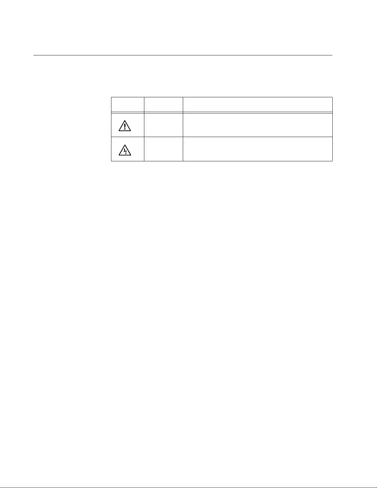
Safety Symbols Used in this Document
This document uses the safety symbols defined in Table 1.
Table 1. Safety Symbols
Symbol Meaning Description
Caution Performing or omitting a specific action may
result in equipment damage or loss of data.
Warning Performing or omitting a specific action may
result in electrical shock.
12
Page 13

Where to Find Web-based Guides
The installation and user guides for all Allied Telesis products are available
in portable document format (PDF) on our web site at
www.alliedtelesis.com. You can view the documents online or download
them onto a local workstation or server.
AT-10408XP 10-Gigabit Ethernet Switch Installation Guide
13
Page 14

Preface
Contacting Allied Telesis
This section provides Allied Telesis contact information for technical
support as well as sales and corporate information.
Online Support You can request technical support online by accessing the Allied Telesis
Knowledge Base from the following web site:
www.alliedtelesis.com/support/kb.aspx. You can use the Knowledge
Base to submit questions to our technical support staff and review
answers to previously asked questions.
Email and
Telephone
Support
For Technical Support via email or telephone, refer to the Allied Telesis
web site: www.alliedtelesis.com. Select your country from the list
displayed on the website. Then select the appropriate menu tab.
Warranty For warranty information, refer to the Allied Telesis web site:
www.alliedtelesis.com/warranty.
Returning
Products
For Sales or
Corporate
Products for return or repair must first be assigned a Return Materials
Authorization (RMA) number. A product sent to Allied Telesis without a
RMA number will be returned to the sender at the sender’s expense.
To obtain an RMA number, contact the Allied Telesis Technical Support
group at our web site: www.alliedtelesis.com/support/rma. Select your
country from the list displayed on the website. Then select the appropriate
menu tab.
You can contact Allied Telesis for sales or corporate information at our
web site: www.alliedtelesis.com. Select your country from the list
displayed on the website. Then select the appropriate menu tab.
Information
14
Page 15

Chapter 1
Overview
The AT-10408XP 10-Gigabit Ethernet Switch is designed to simplify the
task of expanding an Ethernet, Fast Ethernet, or Gigabit Ethernet network.
This chapter contains the following sections:
“Features” on page 16
“Front and Back Panels” on page 17
“Ports” on page 18
“LEDs” on page 19
“Power Supplies and Fan” on page 22
“XFP Transceivers” on page 24
“Network Topology” on page 25
15
Page 16

Chapter 1: Overview
Features
The features of the AT-10408XP 10-Gigabit Ethernet Switch include:
Port status LEDs
Eight XFP (10 Gigabit small form factor pluggable) slots supporting
10GBase-R XFP transceivers
One 10/100/1000Base-T in-band management port with auto MDI/
MDI-X
One RJ-45 style RS-232 terminal port
One SD slot supporting 512KB and 1GB SD cards
IEEE 802.3 and IEEE 802.3u compliant
IEEE 802.3x flow control in full-duplex operation; back pressure in
half-duplex operation
Store and forward switching mode
MAC address table capacity of up to 16K addresses with automatic
aging
CLI configuration using the AT-S83 management software
16
Page 17

Front and Back Panels
Figure 1 illustrates the front panel of the AT-10408XP 10-Gigabit Ethernet
Switch.
AT-10408XP 10-Gigabit Ethernet Switch Installation Guide
Local Management Port
AT-10408XP 10 Gigabit Ether net Switch
1
XFP
PORT ACTIVITY
2
XFP
3
XFP
10G LINK
4
XFP
CLASS 1
LASER PRODUCT
ACT
5
XFP
6
XFP
7
XFP
8
XFP
10/100/1000Base-T
1000 LINK
10/100 LINK
TERMINAL PORT
ACT
ACT
In-band Management Port
SD
STATUS
FAULT
MASTER
PSU1
PSU2
1204
SD Card Slot
NORMAL
BUSY
FAULT
10GBase-R XFP Ports
Figure 1. AT-10408XP Front Panel
Figure 2 illustrates the back panel of the AT-10408XP 10-Gigabit Ethernet
Switch with one AT-FAN01 module and one AT-PWR02 AC power supply
installed.
PSU2
FAULT
AT-FAN01
Fan Module
PWR
GOOD
FAULT
AC INPUT
100-240VAC
50/60Hz
3.0A
AC Power Connector
AT-PWR02
AC Power Supply
PSU1
1205
Figure 2. AT-10408XP Back Panel
17
Page 18

Chapter 1: Overview
Ports
XFP Ports The eight XFP (10-Gigabit small form factor pluggable) slots support
The AT-10408XP 10-Gigabit Ethernet Switch features the following ports:
eight XFP ports, one 10/100/1000Base-T in-band management port, and
one RS-232 terminal port.
10GBase-R XFP transceivers.
10/100/1000
Base-T In-band
Management
Port
RS-232 Terminal
Port
The RJ-45 10/100/1000Base-T in-band management port allows you to
make a remote connection to the switch through Telnet. This port
functions only for network management; it cannot pass switch traffic from
any other port.
Through the terminal port you can make a local connection to the switch
and use the command line AT-S83 management software user interface.
This is an out-of-band management port.
18
Page 19

AT-10408XP 10-Gigabit Ethernet Switch Installation Guide
1
XFP
10/100 LINK
ACT
1000 LINK
ACT
10/100/1000Base-T
LEDs
The AT-10408XP 10-Gigabit Ethernet Switch has four groups of LEDs, as
defined in the following sections:
“XFP Port LED,” next
“10/100/1000Base-T Port LED” on page 19
“SD Card Slot LED” on page 20
“Status LEDs” on page 21
XFP Port LED Each XFP port has one LED as shown in Figure 3 and described in
Table 1.
LED
10/100/1000Base-T
Port LED
1206
Figure 3. XFP Port LED
Table 1. XFP Port LED
LED State Description
L/A Solid green A valid link has been established.
Blinking
The port is transmitting or receiving data.
green
Off No link.
The 10/100/1000Base-T port has one LED as shown in Table 4 and
described in Table 2.
LED
1207
Figure 4. Management Port LED
19
Page 20

Chapter 1: Overview
STATUS
FAULT
SD
BUSY
NORMAL
FAULT
Table 2. Management Port LED
LED Color State Description
L/A Green On A valid link has been established on the
port at 1000 Mbps.
Blinking The port is transmitting or receiving data.
Amber On A valid link has been established on the
port at 10 or 100 Mbps.
Blinking The port is transmitting or receiving data.
None Off No link.
SD Card Slot
LED
The SD card slot has one LED as shown in Figure 5 and described in
Table 3.
LED
1208
Figure 5. SD Card Slot LED
Table 3. SD Card Slot LED
LED Color State Description
Normal Green On The SD card is inserted in the slot and
has been successfully detected.
Busy Green Blinking An SD card is inserted in the slot and is
being accessed by the switch. DO NOT
REMOVE THE SD CARD.
Fault Amber Blinking The SD card is not valid or the system
cannot successfully read or write to the
SD card.
20
Page 21

AT-10408XP 10-Gigabit Ethernet Switch Installation Guide
STATUS
FAULT
MASTER
PSU1
PSU2
Status LEDs The status LEDs are shown in Figure and described in Table 4.
1220
Figure 6. Status LEDs
In the following table, the PSU1 and PSU2 LEDs refer to the slots on the
rear of the chassis. When you are facing the AT-10408XP switch, the
PSU1 LED pertains to the module installed in the left slot and the PSU2
LED pertains to the module installed in the right slot. You can install either
the AT-FAN01 fan module or the AT-PWR02 AC power supply in these
slots.
Table 4. Status LEDs
LED Color State Description
Fault Red On Indicates one of the following:
- There is a system fault.
- One of the five internal fans is bad.
- The voltage is out of range.
- The temperature of the switch is out of
range.
Off Normal operation.
Master Green On The switch is in standalone mode.
Off The switch is not in standalone mode.
PSU1
Green On The PSU installed is supported.
or
PSU2
Off The fan is installed and operating
normally.
Fault
and
PSU1
or
PSU2
Red On Indicates one of the following:
- The PSU temperature threshold is out of
range.
- The fan has failed.
- The bay is empty.
- The PSU installed is not supported.
- The power connection is bad.
21
Page 22

Chapter 1: Overview
Power Supplies and Fan
The switch has two rear power supply slots, which can accommodate the
following combinations of power supplies and fan unit:
Two AT-PWR02 PSU, AC Only power supplies
One AT-PWR02 PSU, AC Only power supply and one AT-FAN01, Fan
Only Module
In order to be operational, the switch MUST have at least one power
supply installed.
Note
For the power requirements, refer to “Power Specifications” on
page 47.
Note
You must power off the AC power to install or remove the
AT-PWR02 AC power supply or the AT-FAN01 fan module. These
modules are not hot swappable.
The AT-FAN01 fan module is shown in Figure 7 and the AT-PWR02 AC
power supply is shown in Figure 8 on page 23.
FA
U
LT
AT-FA N01
Fan M
od
u
le
1209
Figure 7. AT-FAN01, Fan Only Module
22
Page 23

AT-10408XP 10-Gigabit Ethernet Switch Installation Guide
PWR
GOOD
FAU
LT
AC
INPUT
100-240VAC
50/60Hz
3.0A
AT-
PWR02
AC Power Supply
C
A
U
T
IO
N
: D
C
A
IS
U
C
T
O
IO
N
N
N
: D
E
C
IS
T
C
P
O
O
N
W
N
E
E
R
C
T
C
A
O
L
R
L
D
P
P
O
R
W
IO
E
R
R
T
C
O
O
R
R
E
D
M
S
T
O
O
V
A
D
L
IS
O
A
F
B
P
L
S
E
U
S
Y
S
T
E
M
P
O
W
E
R
Figure 8. AT-PWR02 PSU, AC Only
1210
23
Page 24

Chapter 1: Overview
XFP Transceivers
The AT-10408XP 10-Gigabit Ethernet Switch supports the 10GBase-R
XFP models listed in Table 5.
Table 5. Supported 10GBase-R XFPs
Type
10GBase-SR 850 33 (62.5µ MMF) AT-XP8SR
10-GBase-LR 1310 10,000 AT-XP8LR
10-GBase-ER 1550 40,000 AT-XP8ER
Wavelength
(nm)
Distance (m) Model
24
Page 25

Network Topology
Main Office
AT-10408XP 10-Gigabit Ethernet Switch Installation Guide
Figure 9 illustrates deploying the AT-10408XP 10-Gigabit Ethernet Switch
for enterprise network aggregation.
Branch Office
AT-10408XP 10-Gigabit Ethernet Switch
AT-10408XP 10 Gigabit Ethernet Switch
2
1
XFP3XFP4XFP5XFP6XFP7XFP8XFP
XFP
PORT ACTIVITY
10G LINK
ACT
10GbE Links
10GbE SAN Controller
10/100/1000Base-T Switches
Server Farm
CLASS 1
LASER PRODUCT
SD
NORMAL
BUSY
TERMINAL PORT
10/100/1000Base-T
STATUS
FAULT
FAULT
1000 LINK
ACT
MASTER
10/100 LINK
ACT
PSU1
PSU2
1204
10GbE Link
AT-10408XP 10-Gigabit Ethernet Switch
AT-10408XP 10 Gigabit Ethernet Switch
2
1
XFP3XFP4XFP5XFP6XFP7XFP8XFP
XFP
PORT ACTIVITY
CLASS 1
LASER PRODUCT
10G LINK
ACT
10GbE Links
SD
NORMAL
BUSY
TERMINAL PORT
10/100/1000Base-T
STATUS
FAULT
FAULT
1000 LINK
ACT
MASTER
10/100 LINK
ACT
PSU1
PSU2
1204
10GbE SAN Controller
10/100/1000Base-T Switches
10/100/1000Base-T Switches
10/100/1000Base-T Switches
Figure 9. Enterprise Network Aggregation
In Figure 9, switches and server farms aggregate at 10/100/1000Base-T
switches. Those switches, as well as 10Gb Ethernet SAN controllers
aggregate at AT-10408XP 10-Gigabit Ethernet Switches, one in the main
office and one in the branch office.
25
Page 26

Chapter 1: Overview
26
Page 27

Chapter 2
Installation
This chapter contains the following sections:
“Reviewing Safety Precautions” on page 28
“Selecting a Site for the Switch” on page 30
“Unpacking the Switch” on page 31
“Installing the Switch on a Desktop” on page 32
“Installing the Switch in a Rack” on page 33
“Installing an XFP Transceiver” on page 36
“Cabling and Powering On the Switch” on page 38
“Starting a Local Management Session” on page 41
“Warranty Registration” on page 43
27
Page 28

Chapter 2: Installation
Reviewing Safety Precautions
Please review the following safety precautions before you begin to install
the chassis or any of its components.
Note
The indicates that a translation of the safety statement is
available in a PDF document titled “Translated Safety Statements”
(613-000405) on the Allied Telesis website at
www.alliedtelesis.com.
Warning: To prevent electric shock, do not remove the cover.
No user-serviceable parts inside. This unit contains hazardous
voltages and should only be opened by a trained and qualified
technician. To avoid the possibility of electric shock, disconnect
electric power to the product before connecting or disconnecting
the LAN cables.
E1
Warning: Do not work on equipment or cables during periods of
lightning activity.
Warning: Power cord is used as a disconnection device. To deenergize equipment, disconnect the power cord.
Warning: Class I Equipment. This equipment must be earthed.
The power plug must be connected to a properly wired earth
ground socket outlet. An improperly wired socket outlet could
place hazardous voltages on accessible metal parts.
Pluggable Equipment. The socket outlet shall be installed near
the equipment and shall be easily accessible.
Caution: Air vents must not be blocked and must have free
access to the room ambient air for cooling.
Warning: Operating Temperature. This product is designed for a
maximum ambient temperature of 40° degrees C.
E2
E6
E5
E3
E7
E4
28
All Countries: Install product in accordance with local and
National Electrical Codes.
E8
Page 29

AT-10408XP 10-Gigabit Ethernet Switch Installation Guide
Circuit Overloading: Consideration should be given to the
connection of the equipment to the supply circuit and the effect
that overloading of circuits might have on overcurrent protection
and supply wiring. Appropriate consideration of equipment
nameplate ratings should be used when addressing this
concern.
E21
Caution: Risk of explosion if battery is replaced by an incorrect
type. Replace only with the same or equivalent type
recommended by the manufacturer. Dispose of used batteries
according to the manufacturer’s instructions.
Attention: Le remplacement de la batterie par une batterie de
type incorrect peut provoquer un danger d’explosion. La
remplacer uniquement par une batterie du même type ou de type
équivalent recommandée par le constructeur. Les batteries
doivent être éliminées conformément aux instructions du
constructeur.
E22
Warning: Mounting of the equipment in the rack should be such
that a hazardous condition is not created due to uneven
mechanical loading.
E25
If installed in a closed or multi-unit rack assembly, the operating
ambient temperature of the rack environment may be greater
than the room ambient temperature. Therefore, consideration
should be given to installing the equipment in an environment
compatible with the manufacturer’s maximum rated ambient
temperature (Tmra). E35
Caution: Installation of the equipment in a rack should be such
that the amount of air flow required for safe operation of the
equipment is not compromised.
E36
Warning: Reliable earthing of rack-mounted equipment should
be maintained. Particular attention should be given to supply
connections other than direct connections to the branch circuits
(e.g., use of power strips).
E37
29
Page 30

Chapter 2: Installation
Selecting a Site for the Switch
Observe the following requirements when choosing a site for your switch:
If you plan to install the switch in an equipment rack, ensure that the
rack is safely secured and that it will not tip over. Devices in a rack
should be installed starting at the bottom, with the heavier devices
near the bottom of the rack.
If you are installing the switch on a table, ensure that the table is level
and secure.
The power outlet for the switch should be located near the unit and
should be easily accessible.
The site should provide for easy access to the ports on the front of the
switch. This will make it easy for you to connect and disconnect
cables, as well as view the switch’s LEDs.
To allow proper cooling of the switch, air flow around the unit and
through its vents on the side and rear should not be restricted.
Do not place objects on top of the switch.
Do not expose the switch to moisture or water.
Ensure that the site is a dust-free environment.
You should use dedicated power circuits or power conditioners to
supply reliable electrical power to the network devices.
30
Page 31

Unpacking the Switch
To unpack the switch, perform the following procedure:
1. Remove all components from the shipping package.
2. Place the switch on a level, secure surface.
3. Ensure the following hardware components are included in your switch
AT-10408XP 10-Gigabit Ethernet Switch Installation Guide
Note
Store the packaging material in a safe location. You must use the
original shipping material if you need to return the unit to Allied
Telesis.
package. If any item is missing or damaged, contact your Allied Telesis
sales representative for assistance.
Two rack-mount brackets
Eight rack-mount bracket screws (stainless steel)
One management cable
Four power cords (one each for North America, the UK, Europe,
and Australia)
Documentation CD
31
Page 32

Chapter 2: Installation
Installing the Switch on a Desktop
You can place AT-10408XP 10-Gigabit Ethernet Switch on a desktop or
install it in a 19-inch rack. To install the switch in a rack, refer to “Installing
the Switch in a Rack” on page 33.
To place the switch on a desktop, perform the following procedure:
1. Remove all equipment from the package and store the packaging
material in a safe place.
2. Place the switch on a flat, secure surface (such as a desk or table)
leaving ample space around the unit for ventilation.
32
Page 33

Installing the Switch in a Rack
To install the AT-10408XP 10-Gigabit Ethernet Switch in a rack, perform
the following procedure:
1. If attached, remove the rubber feet using a flat-head screwdriver.
2. Install a bracket on one side of the switch using a Phillips screwdriver
and four of the rack-mount screws included with the switch, as shown
in Figure 10.
AT-10408XP
10 Gigabit Ethernet Switch
1
2
XFP
XFP
AT-10408XP 10-Gigabit Ethernet Switch Installation Guide
3
P
OR
T
A
C
T
IV
IT
1
Y
0G
L
I
N
K
4
A
C
XFP
T
C
L
A
S
L
A
S
S
1
E
R
P
R
O
D
U
C
T
5
XFP
6
XFP
7
XFP
8
XFP
10/100/1000B
ase-T
XFP
1
0
00
L
I
N
K
TERMINAL POR
1
0
/1
00
L
IN
K
SD
A
C
T
T
A
C
T
STA
NORMAL
TUS
FA
U
BU
LT
S
Y
MASTER
FAULT
PSU1
PSU2
1211
Figure 10. Attaching the Rack-Mount Bracket
3. Repeat step 2 to attach the remaining bracket to the other side of the
switch.
33
Page 34

Chapter 2: Installation
4. Mount the switch on a 19-inch rack using four screws (not included),
as shown in Figure 11
AT-10408XP
10 Gigabit Ethernet Switch
1
2
XFP
3
XFP
P
O
R
T
A
C
T
I
V
IT
1
Y
0
G
L
I
N
K
4
A
C
XFP
T
C
L
A
S
L
A
S
S
1
E
R
P
R
O
D
U
C
T
5
XFP
6
XFP
7
XFP
8
XFP
10/100/1000B
ase-T
XFP
1
0
0
0
L
IN
K
TER
MINAL POR
1
0
/1
0
0 L
IN
SD
A
C
T
K
T
A
C
T
STA
NOR
TUS
MAL
FA
U
BU
LT
S
Y
MASTER
FAU
LT
PSU1
PSU2
1212
Figure 11. Mounting the Switch on the Rack
Warning: To prevent electric shock, do not remove the cover.
No user-serviceable parts inside. This unit contains hazardous
voltages and should only be opened by a trained and qualified
technician. To avoid the possibility of electric shock, disconnect
electric power to the product before connecting or disconnecting
the LAN cables.
E1
Warning: Do not work on equipment or cables during periods of
lightning activity.
E2
Warning: Power cord is used as a disconnection device. To de-
energize equipment, disconnect the power cord.
E3
Warning: Class I Equipment. This equipment must be earthed.
The power plug must be connected to a properly wired earth
ground socket outlet. An improperly wired socket outlet could
place hazardous voltages on accessible metal parts.
E4
Pluggable Equipment. The socket outlet shall be installed near
the equipment and shall be easily accessible.
E5
Caution: Air vents must not be blocked and must have free
access to the room ambient air for cooling.
E6
Warning: Operating Temperature. This product is designed for a
maximum ambient temperature of 40° degrees C.
E7
34
Page 35

AT-10408XP 10-Gigabit Ethernet Switch Installation Guide
Circuit Overloading: Consideration should be given to the
connection of the equipment to the supply circuit and the effect
that overloading of circuits might have on overcurrent protection
and supply wiring. Appropriate consideration of equipment
nameplate ratings should be used when addressing this
concern.
E21
Warning: Mounting of the equipment in the rack should be such
that a hazardous condition is not created due to uneven
mechanical loading.
E25
If installed in a closed or multi-unit rack assembly, the operating
ambient temperature of the rack environment may be greater
than the room ambient temperature. Therefore, consideration
should be given to installing the equipment in an environment
compatible with the manufacturer’s maximum rated ambient
temperature (Tmra). E35
Caution: Installation of the equipment in a rack should be such
that the amount of air flow required for safe operation of the
equipment is not compromised.
E36
Warning: Reliable earthing of rack-mounted equipment should
be maintained. Particular attention should be given to supply
connections other than direct connections to the branch circuits
(e.g., use of power strips).
E37
35
Page 36

Chapter 2: Installation
Installing an XFP Transceiver
The AT-10408XP 10-Gigabit Ethernet Switch has eight XFP ports.
Note
The transceiver can be hot-swapped; you do not need to power off
the switch to install a transceiver. However, always remove the
cables before removing the transceiver.
Note
You must install the transceiver before you connect cables to it.
To install an XFP transceiver, perform the following procedure:
1. Remove the transceiver from its shipping container and store the
packaging material in a safe location.
Warning
An XFP transceiver can be damaged by static electricity. Be sure to
observe all standard electrostatic discharge (ESD) precautions,
such as wearing an antistatic wrist strap, to avoid damaging the
transceiver.
2. Remove the dust plug from the XFP slot, as shown in Figure 12.
7
XFP
8
XFP
1000 LINK
TERMINAL PORT10/100/1000Base-T
10/100 LI
ACT
NK
ACT
SD
STATUS
F
AULT
MASTER
PSU1
PSU2
1213
NO
RM
AL
BUSY
FAULT
Figure 12. Removing the Dust Plug from the XFP Slot
36
3. Locate the label on the transceiver and turn it so that the label is on the
bottom.
Page 37

AT-10408XP 10-Gigabit Ethernet Switch Installation Guide
4. Slide the XFP transceiver into an XFP slot on the switch, as shown in
Figure 13.
7
XFP
8
XFP
1000 LINK
TERMINAL PORT10/100/1000Base-T
10/100 LI
ACT
NK
ACT
SD
STATUS
NO
RMAL
FAULT
BUSY
MASTER
FA
U
LT
PSU1
PSU2
1214
Figure 13. Inserting the XFP
5. Repeat steps 2 through 4 if you are installing other XFP transceivers.
Note
XFP transceivers are dust sensitive. When a fiber optic cable is not
installed, or when you store the XFP, always keep the plug in the
optical bores. When you do remove the plug, keep it for future use.
Note
Unnecessary removal and insertion of an XFP can lead to premature
failure.
For information about cabling for the XFP, consult the documentation
that was shipped with the XFP.
37
Page 38

Chapter 2: Installation
Cabling and Powering On the Switch
Connecting a
XFP Fiber Optic
Cable
To connect a fiber optic cable to an XFP installed in the AT-10408XP 10Gigabit Ethernet Switch, perform the following procedure:
1. Remove the dust plug from the XFP, as shown in Figure 14.
7
XFP
8
XFP
1000 LINK
TER
MINAL PORT10/100/1000Base-T
10/100 LI
ACT
NK
ACT
SD
STATUS
NO
RMAL
FAULT
BUSY
MASTER
FA
U
L
PSU1
T
PSU2
1216
Figure 14. Removing the Dust Cover from the XFP
2. Connect the fiber optic cable to the XFP port, as shown in Figure 15.
7
XFP
8
XFP
1000 LINK
TER
MINAL PORT10/100/1000Base-T
10/100 LI
ACT
NK
ACT
SD
STATUS
NO
RM
AL
FAULT
BUSY
MASTER
FAULT
PSU1
PSU2
1215
Figure 15. Connecting the Fiber Optic Cable
38
Page 39

AT-10408XP 10-Gigabit Ethernet Switch Installation Guide
Connecting the
10/100/1000
Base-T In-band
Management
Port
To connect the cable to the 10/100/1000Base-T in-band management
port, perform the following procedure:
1. Plug the cable into the port, as shown in Figure 16.
7
XFP
8
XFP
1000 LINK
TER
MINAL PORT10/100/1000Base-T
10/100 LI
ACT
NK
ACT
SD
STATUS
NORM
AL
FAULT
BUSY
MASTER
FAULT
PSU1
PSU2
1217
Figure 16. Connecting the 10/100/1000Base-T Cable
Note
For cabling specifications, refer to “In-band Management Port
Cabling” on page 49.
Connecting to the
RJ-45 Style
RS-232 Terminal
Port
To connect to the RJ-45 style RS-232 terminal port, perform the following
procedure:
1. Plug the cable into the port, as shown in Figure 17.
7
XFP
8
XFP
1000 LINK
TER
MINAL PORT10/100/1000Base-T
10/100 LI
ACT
NK
ACT
SD
STATUS
NO
RMAL
FAULT
BUSY
MASTER
FAULT
PSU1
PSU2
1218
Figure 17. Connecting to the Terminal Port
39
Page 40

Chapter 2: Installation
Note
For the terminal port pinouts, refer to “RJ-45 Style RS-232 Terminal
Port Pinouts” on page 48.
Powering On the
Switch
To power on the switch, perform the following procedure:
1. Plug the power cord into the AC power connector on the back of the
switch, as shown in Figure 18.
PW
R
G
O
OD
FA
U
LT
AC
IN
P
UT
10
0-240V
A
C
5
0/60Hz
3.0A
AT-PWR02
AC Power Supply
CA
U
T
IO
N
: D
C
A
IS
UT
CO
IO
NN
N: D
EC
IS
T
C
P
O
O
N
W
N
ER
E
C
C
T
AL
O
R
L
D P
P
O
R
W
I
O
E
R
R
C
T
O
O
R
R
EM
D
S
T
O
O
V
A
D
L
IS
O
A
F
B
P
LE S
S
U
Y
STE
M
P
O
W
E
R
1219
Figure 18. Plugging in the AC Power Cord
2. Plug the other end of the power cord into a wall outlet.
Warning: Power cord is used as a disconnection device. To de-
energize equipment, disconnect the power cord.
5
40
Pluggable Equipment. The socket outlet shall be installed near
the equipment and shall be easily accessible.
7
3. Verify that the POWER LED is green. If the LED is OFF, refer to
Chapter 3, “Troubleshooting” on page 45.
The switch is now powered on and ready for network operations. To
start a local management session on the switch, refer to “Starting a
Local Management Session” on page 41. To start a remote
management session, the switch must have an IP address. For
information about giving the switch an IP address and starting a
remote management session, refer to the AT-S83 Management
Software Command Line Interface User’s Guide.
Page 41

Starting a Local Management Session
To start a local management session on an AT-10408XP 10-Gigabit
Ethernet Switch, perform the following procedure:
1. Connect one end of the RJ-45 style RS-232 terminal cable to the
terminal port on the switch, as shown in Figure 19.
7
XFP
8
XFP
AT-10408XP 10-Gigabit Ethernet Switch Installation Guide
1000 LINK
TERMINAL PORT10/100/1000Base-T
10/100 LI
ACT
NK
ACT
SD
STATUS
FAULT
MASTER
PSU1
PSU2
1218
NO
RM
AL
BUSY
FAULT
Figure 19. Connecting the RJ-45 Style Terminal Cable
2. Connect the other end of the cable to the port on a terminal or PC with
a terminal emulator program.
3. Configure the terminal or terminal emulator program as follows:
Baud rate: 9600
Data bits: 8
Stop bits: 1
Flow control: None
Note
These default settings are for a DEC VT100 or ANSI terminal, or an
equivalent terminal emulation program.
1. Type the user id and password.
There are two default user ids and passwords. For the system
administrator login, the default user id is “manager” and the default
password is “friend.” For the operator login, the default user id is
“operator” and the default password is “operator.”
41
Page 42

Chapter 2: Installation
A command line prompt is displayed in Figure 20.
Username:manager
Password:
(none) #
Figure 20. Command Line Login Screen
The default switch name is “(none)” and the pound sign (#) prompt
indicates the Privileged Exec mode which is the default mode
accessed by the manager login.
For detailed information about configuring the AT-10408XP 10-Gigabit
Ethernet Switch, refer to the AT-S83 Management Software Command
Line Interface User’s Guide.
42
Page 43

Warranty Registration
Allied Telesis hardware products are covered under limited warranties.
Some products have a longer warranty coverage than others.
The AT-10408XP 10-Gigabit Ethernet Switch has a limited lifetime
warranty (24 months fan & PSU).
All Allied Telesis warranties are subject to the terms and conditions set out
on the Allied Telesis website at www.alliedtelesis.com/warranty.
AT-10408XP 10-Gigabit Ethernet Switch Installation Guide
43
Page 44

Chapter 2: Installation
44
Page 45

Chapter 3
Troubleshooting
This chapter contains information on how to troubleshoot the switch in the
event that a problem occurs.
Note
If you need further assistance, please contact Allied Telesis
Technical Support. Refer to “Contacting Allied Telesis” on page 14.
Check the Status LEDs on the front of the switch. If the PSU1 or the PSU2
LED is red and the FAULT LED is red, then there may be a problem with
the unit not receiving power. Do the following:
Ensure that the power cord is securely connected to the power source
and to the AC connector on the back panel of the switch.
Verify that the power outlet has power by connecting another device
to it.
Try connecting the unit to another power source.
Try using a different power cord.
Verify that the voltage from the power source is within the required
levels for your region.
Verify that the LINK/ACT LED for the in-band management port is ON. If a
LINK/ACT LED is OFF, do the following:
Verify that the twisted pair cable is securely connected to the port on
the switch and to the port on the end node.
Ensure that the twisted pair cable does not exceed 100 meters (328
feet).
Verify that you are using the appropriate category of twisted pair cable:
Category 3 or better for 10 Mbps operation and Category 5 and
Category 5E for 100 and 1000 Mbps operation.
45
Page 46

Chapter 3: Troubleshooting
46
Page 47

Appendix A
Technical Specifications
Physical Specifications
Dimensions: 440 mm x 438mm x 43.6 mm
(17.36 in x 17.36 in x 1.72 in)
Weight: As shipped: 5.85 kg (12.9 lbs)
Environmental Specifications
Operating Temperature: 0º C to 40º C (32º F to 104º F)
Storage Temperature: -20º C to 60º C (-4º F to 140º F)
Operating Humidity: Less than 80% non-condensing
Storage Humidity: Less than 95% non-condensing
Operating Altitude Range: Up to 3,000 m (9,843 ft)
Power Specifications
Input Supply Voltage: AT-PWR02 AC power supply:
100/240 VAC, 47/63 Hz input
Power Consumption: AT-PWR02 AC power supply:
2.2A at 100 V, 1.1 A at 230 V
Safety and Electromagnetic Emissions Certifications
EMI/RFI: FCC Class A, EN55022 Class A,
CISPR Class A, C-TICK
Immunity: EN55024
Electrical Safety: EN60950-1 (TUV), UL60950-1 (
cULus
), CE
47
Page 48

Appendix A: Technical Specifications
RJ-45 Style RS-232 Terminal Port Pinouts
Figure 1 illustrates the pin layout and Table 1 describes the pinouts for the
RJ-45 style RS-232 terminal port.
1
Figure 1. RJ-45 Connector and Port Pin Layout.
Table 1. RJ-45 Style RS-232 Port Pinouts
Pin Signal
1 Request to Send
2Not Used
8
8
1
3 Transmit Data
4 Ground
5 Ground
6 Receive Data
7Not Used
8 Clear to Send
48
Page 49

In-band Management Port Cabling
Table 2 contains the cabling specifications for the in-band management
port.
Table 2. In-band Management Port Cabling and Distances
Speed Type of Cable
AT-10408XP 10-Gigabit Ethernet Switch Installation Guide
Maximum
Operating
Distance
10 Mbps Category 3 or better 100-ohm shielded or
unshielded twisted pair cable
100 Mbps Category 5 or Category 5E (Enhanced) 100-
ohm shielded or unshielded twisted pair cable
1000 Mbps Category 5 and Category 5E (Enhanced) 100-
ohm shielded or unshielded twisted pair cable
100 m (328 ft)
100 m (328 ft)
100 m (328 ft)
49
Page 50

Appendix A: Technical Specifications
50
 Loading...