

Page 1

AlliedView™-EMS 4.0.1
DEVICE MANAGEMENT GUIDE
AlliedView™-EMS 4.0.1 Device Management Guide Page 1 of 411
Page 2

TABLE OF CONTENTS
BASIC OPERATIONS........................................................................................................................................................... 9
COMMON OPERATIONS ON THE MAIN WINDOW ................................................................................................................ 9
MENU FOR STACKED DEVICES............................................................................................................................................... 10
PORT SELECTION DIALOG BOX............................................................................................................................................. 11
PORT STATUS COLORS ..........................................................................................................................................................11
LED STATUS ...........................................................................................................................................................................11
UTILIZATION ..........................................................................................................................................................................12
LAYER 2 SWITCHES..........................................................................................................................................................13
AT-8000 SERIES ..................................................................................................................................................................... 13
Main Window..................................................................................................................................13
Agent Menu......................................................................................................................................20
Bridge Menu.....................................................................................................................................21
RMON Menu...................................................................................................................................22
Port Menu ........................................................................................................................................22
Stacking Menu..................................................................................................................................24
Expansion Module Notes..............................................................................................................24
AT-8000/8POE.....................................................................................................................................................................26
Main Window..................................................................................................................................26
Agent Menu......................................................................................................................................27
Bridge Menu.....................................................................................................................................28
RMON Menu...................................................................................................................................28
Port Menu ........................................................................................................................................29
AT-8000GS SERIES................................................................................................................................................................31
Main Window..................................................................................................................................32
Agent Menu......................................................................................................................................33
Routing Menu ..................................................................................................................................40
Bridge Menu.....................................................................................................................................44
IGMP Menu ......................................................................................................................................46
Security Menu..................................................................................................................................46
RMON Menu...................................................................................................................................50
Port Menu ........................................................................................................................................51
AT-8000S SERIES...................................................................................................................................................................57
Main Window..................................................................................................................................57
Agent Menu......................................................................................................................................59
Routing Menu ..................................................................................................................................65
Bridge Menu.....................................................................................................................................68
IGMP Menu ......................................................................................................................................69
Security Menu..................................................................................................................................70
RMON Menu...................................................................................................................................73
Port Menu ........................................................................................................................................74
AT-8300GB SERIES ...............................................................................................................................................................79
Main Window..................................................................................................................................80
Agent Menu......................................................................................................................................82
Bridge Menu.....................................................................................................................................83
RMON Menu...................................................................................................................................83
Port Menu ........................................................................................................................................84
Stacking Menu..................................................................................................................................85
AlliedView™-EMS 4.0.1 Device Management Guide Page 2 of 411
Page 3

AT-8400 ................................................................................................................................................................................ 86
Main Window..................................................................................................................................87
Agent Menu......................................................................................................................................88
Bridge Menu.....................................................................................................................................89
RMON Menu...................................................................................................................................90
Port Menu ........................................................................................................................................90
Stacking Menu..................................................................................................................................92
AT-8400 LINE CARDS...........................................................................................................................................................93
AT-8411............................................................................................................................................93
AT-8412............................................................................................................................................94
AT-8413............................................................................................................................................95
AT-8414............................................................................................................................................96
AT-9000/24...........................................................................................................................................................................97
Main Window..................................................................................................................................97
Agent Menu......................................................................................................................................98
Bridge Menu.....................................................................................................................................99
RMON Menu...................................................................................................................................99
Port Menu ..................................................................................................................................... 100
AT-9006 FAMILY .................................................................................................................................................................102
Main Window............................................................................................................................... 102
Agent Menu................................................................................................................................... 103
Bridge Menu.................................................................................................................................. 104
RMON Menu................................................................................................................................ 104
VLAN Menu.................................................................................................................................. 105
Port Menu ..................................................................................................................................... 105
AT-9410GB.........................................................................................................................................................................106
Main Window............................................................................................................................... 106
Agent Menu................................................................................................................................... 107
Bridge Menu.................................................................................................................................. 108
RMON Menu................................................................................................................................ 108
Port Menu ..................................................................................................................................... 109
ROUTERS...........................................................................................................................................................................111
AT-AR400S SERIES .............................................................................................................................................................111
Main Window............................................................................................................................... 111
Agent Menu................................................................................................................................... 114
Routing Menu ............................................................................................................................... 114
Bridge Menu.................................................................................................................................. 115
ATM Menu .................................................................................................................................... 115
ADSL Menu................................................................................................................................... 116
SHDSL Menu ................................................................................................................................ 116
Port Menu ..................................................................................................................................... 117
AT-AR410...........................................................................................................................................................................118
Main Window............................................................................................................................... 118
Agent Menu................................................................................................................................... 119
Routing Menu ............................................................................................................................... 119
Bridge Menu.................................................................................................................................. 120
Frame Relay Menu....................................................................................................................... 120
Call List Menu............................................................................................................................... 120
AlliedView™-EMS 4.0.1 Device Management Guide Page 3 of 411
Page 4

Port Menu ..................................................................................................................................... 121
AT-AR700 SERIES................................................................................................................................................................122
Main Window............................................................................................................................... 122
Agent Menu................................................................................................................................... 124
Routing Menu ............................................................................................................................... 124
Bridge Menu.................................................................................................................................. 125
Frame Relay Menu....................................................................................................................... 125
Call List Menu............................................................................................................................... 125
Port Menu ..................................................................................................................................... 126
AT-AR700S SERIES .............................................................................................................................................................127
Main Window............................................................................................................................... 127
Agent Menu................................................................................................................................... 129
Routing Menu ............................................................................................................................... 132
LAN/WAN Menu ........................................................................................................................ 134
Availability Menu.......................................................................................................................... 138
Security Menu............................................................................................................................... 139
RMON Menu................................................................................................................................ 141
Port Menu ..................................................................................................................................... 141
ADVANCED LAYER 2 SWITCHES...............................................................................................................................143
AT-8500 SERIES ...................................................................................................................................................................143
Main Window............................................................................................................................... 143
Agent Menu................................................................................................................................... 146
Routing Menu ............................................................................................................................... 148
Bridge Menu.................................................................................................................................. 149
RMON Menu................................................................................................................................ 149
Port Menu ..................................................................................................................................... 150
Stacking Menu............................................................................................................................... 153
Expansion Module Notes........................................................................................................... 153
AT-8700XL SERIES..............................................................................................................................................................155
Main Window............................................................................................................................... 155
Agent Menu................................................................................................................................... 157
Routing Menu ............................................................................................................................... 158
Bridge Menu.................................................................................................................................. 158
Port Menu ..................................................................................................................................... 159
LAYER 3 SWITCHES........................................................................................................................................................160
AT-8600 SERIES ...................................................................................................................................................................160
Main Window............................................................................................................................... 160
Agent Menu................................................................................................................................... 162
Routing Menu ............................................................................................................................... 163
Bridge Menu.................................................................................................................................. 163
Port Menu ..................................................................................................................................... 164
Expansion Module Notes........................................................................................................... 164
AT-8800 SERIES ...................................................................................................................................................................165
Main Window............................................................................................................................... 165
Agent Menu................................................................................................................................... 166
Routing Menu ............................................................................................................................... 167
Bridge Menu.................................................................................................................................. 168
Port Menu ..................................................................................................................................... 168
AlliedView™-EMS 4.0.1 Device Management Guide Page 4 of 411
Page 5

AT-8948 ..............................................................................................................................................................................170
Main Window............................................................................................................................... 170
Agent Menu................................................................................................................................... 171
Routing Menu ............................................................................................................................... 174
Bridge Menu.................................................................................................................................. 175
LLDP Menu ................................................................................................................................... 176
Availability Menu.......................................................................................................................... 177
Security Menu............................................................................................................................... 179
RMON Menu................................................................................................................................ 180
Port Menu ..................................................................................................................................... 180
AT-X900-48 SERIES.............................................................................................................................................................183
Main Window............................................................................................................................... 183
Agent Menu................................................................................................................................... 185
Routing Menu ............................................................................................................................... 187
Bridge Menu.................................................................................................................................. 189
LLDP Menu ................................................................................................................................... 190
Availability Menu.......................................................................................................................... 191
Security Menu............................................................................................................................... 192
RMON Menu................................................................................................................................ 194
Port Menu ..................................................................................................................................... 194
RAPIER...................................................................................................................................................................................197
Main Window............................................................................................................................... 197
Agent Menu................................................................................................................................... 202
Routing Menu ............................................................................................................................... 203
BRIDGE MENU ......................................................................................................................................................................203
Frame Relay Menu....................................................................................................................... 204
Call List Menu............................................................................................................................... 204
Port Menu ..................................................................................................................................... 205
AT-RAPIER 48W ..................................................................................................................................................................206
Main Window............................................................................................................................... 206
Agent Menu................................................................................................................................... 207
Routing Menu ............................................................................................................................... 210
LAN/WAN Menu ........................................................................................................................ 212
Availability Menu.......................................................................................................................... 215
Security Menu............................................................................................................................... 217
RMON Menu................................................................................................................................ 218
Port Menu ..................................................................................................................................... 218
SWITCHBLADE .....................................................................................................................................................................221
Main Window............................................................................................................................... 222
Agent Menu................................................................................................................................... 224
Routing Menu ............................................................................................................................... 225
Bridge Menu.................................................................................................................................. 225
Port Menu ..................................................................................................................................... 226
SWITCHBLADE LINE CARDS.......................................................................................................................................228
MULTI-LAYER GIGABIT SWITCHES ...........................................................................................................................231
AT-9400 SERIES ...................................................................................................................................................................231
Main Window............................................................................................................................... 231
Agent Menu................................................................................................................................... 236
AlliedView™-EMS 4.0.1 Device Management Guide Page 5 of 411
Page 6

Routing Menu ............................................................................................................................... 239
Bridge Menu.................................................................................................................................. 240
Security Menu............................................................................................................................... 241
RMON Menu................................................................................................................................ 242
Port Menu ..................................................................................................................................... 243
Stacking Menu............................................................................................................................... 246
AT-9700 SERIES ...................................................................................................................................................................247
Main Window............................................................................................................................... 247
Agent Menu................................................................................................................................... 250
Routing Menu ............................................................................................................................... 253
Bridge Menu.................................................................................................................................. 262
IGMP Menu ................................................................................................................................... 263
VRRP Menu................................................................................................................................... 264
Security Menu............................................................................................................................... 265
RMON Menu................................................................................................................................ 270
Port Menu ..................................................................................................................................... 271
Expansion Module Notes........................................................................................................... 275
AT-9800 SERIES ...................................................................................................................................................................276
Main Window............................................................................................................................... 276
Agent Menu................................................................................................................................... 278
Routing Menu ............................................................................................................................... 279
Bridge Menu.................................................................................................................................. 279
Port Menu ..................................................................................................................................... 280
AT-9900/AT-9900S SERIES................................................................................................................................................281
Main Window............................................................................................................................... 281
Agent Menu................................................................................................................................... 284
Routing Menu ............................................................................................................................... 284
Bridge Menu.................................................................................................................................. 285
Port Menu ..................................................................................................................................... 285
AT-X600 SERIES...................................................................................................................................................................287
Main Window............................................................................................................................... 287
Agent Menu................................................................................................................................... 291
Routing Menu ............................................................................................................................... 298
Bridge Menu.................................................................................................................................. 300
Availability Menu.......................................................................................................................... 301
RMON Menu................................................................................................................................ 301
Port Menu ..................................................................................................................................... 301
Stacking Menu............................................................................................................................... 305
AT-X900-12X SERIES..........................................................................................................................................................306
Main Window............................................................................................................................... 306
Agent Menu................................................................................................................................... 308
Routing Menu ............................................................................................................................... 314
Bridge Menu.................................................................................................................................. 316
Availability Menu.......................................................................................................................... 317
RMON Menu................................................................................................................................ 317
Port Menu ..................................................................................................................................... 318
Stacking Menu............................................................................................................................... 321
AT-X900-24X SERIES (ALLIEDWARE)...............................................................................................................................322
Main Window............................................................................................................................... 322
AlliedView™-EMS 4.0.1 Device Management Guide Page 6 of 411
Page 7

Agent Menu................................................................................................................................... 324
Routing Menu ............................................................................................................................... 328
Bridge Menu.................................................................................................................................. 329
LLDP Menu ................................................................................................................................... 330
Security Menu............................................................................................................................... 331
RMON Menu................................................................................................................................ 333
Port Menu ..................................................................................................................................... 333
AT-X900-24X SERIES (ALLIEDWARE PLUS) .....................................................................................................................337
Main Window............................................................................................................................... 337
Agent Menu................................................................................................................................... 339
Routing Menu ............................................................................................................................... 346
Bridge Menu.................................................................................................................................. 348
Availability Menu.......................................................................................................................... 349
RMON Menu................................................................................................................................ 349
Port Menu ..................................................................................................................................... 350
Stacking Menu............................................................................................................................... 353
SWITCHBLADE X908...........................................................................................................................................................354
Main Window............................................................................................................................... 354
Agent Menu................................................................................................................................... 356
ROUTING MENU ..................................................................................................................................................................362
BRIDGE MENU ......................................................................................................................................................................364
AVAILABILITY MENU ............................................................................................................................................................365
RMON MENU .....................................................................................................................................................................365
PORT MENU .........................................................................................................................................................................366
Stacking Menu............................................................................................................................... 369
MEDIA CONVERTERS.....................................................................................................................................................371
CONVERTEON SERIES ..........................................................................................................................................................371
Main Window............................................................................................................................... 371
AGENT MENU ......................................................................................................................................................................374
STATUS MENU......................................................................................................................................................................375
OAM Menu ................................................................................................................................... 377
CONVERTEON SERIES MODULES ........................................................................................................................................378
AT-MCF2000 MEDIA CONVERTER ...................................................................................................................................386
MAIN WINDOW ..................................................................................................................................................................386
AGENT MENU ......................................................................................................................................................................388
STATUS MENU......................................................................................................................................................................390
AT-MCF2000 MODULES....................................................................................................................................................392
AT-MCF2000M ............................................................................................................................ 392
AT-MCF2000S.............................................................................................................................. 392
AT-MCF2012LC .......................................................................................................................... 393
AT-MCF2012LC/1....................................................................................................................... 393
POWERBLADE ......................................................................................................................................................................395
Main Window............................................................................................................................... 395
AGENT MENU ......................................................................................................................................................................396
Status Menu................................................................................................................................... 397
POWERBLADE MODULES ....................................................................................................................................................398
AT-PB10 Series Media Converter Modules .......................................................................... 398
AT-PB100 Series Media Converter Modules ........................................................................ 399
AT-PB200 Series Switch Modules............................................................................................ 400
AT-PB300 Series Media Converter Modules ........................................................................ 401
AlliedView™-EMS 4.0.1 Device Management Guide Page 7 of 411
Page 8

AT-PB1000 Series Media Converter Modules...................................................................... 402
EXPANSION GATEWAYS .............................................................................................................................................403
PORT INTERFACE CARDS ....................................................................................................................................................403
NETWORK SERVICE MODULES ...........................................................................................................................................405
UPLINK MODULES................................................................................................................................................................407
AlliedView™-EMS 4.0.1 Device Management Guide Page 8 of 411
Page 9
Basic Operations
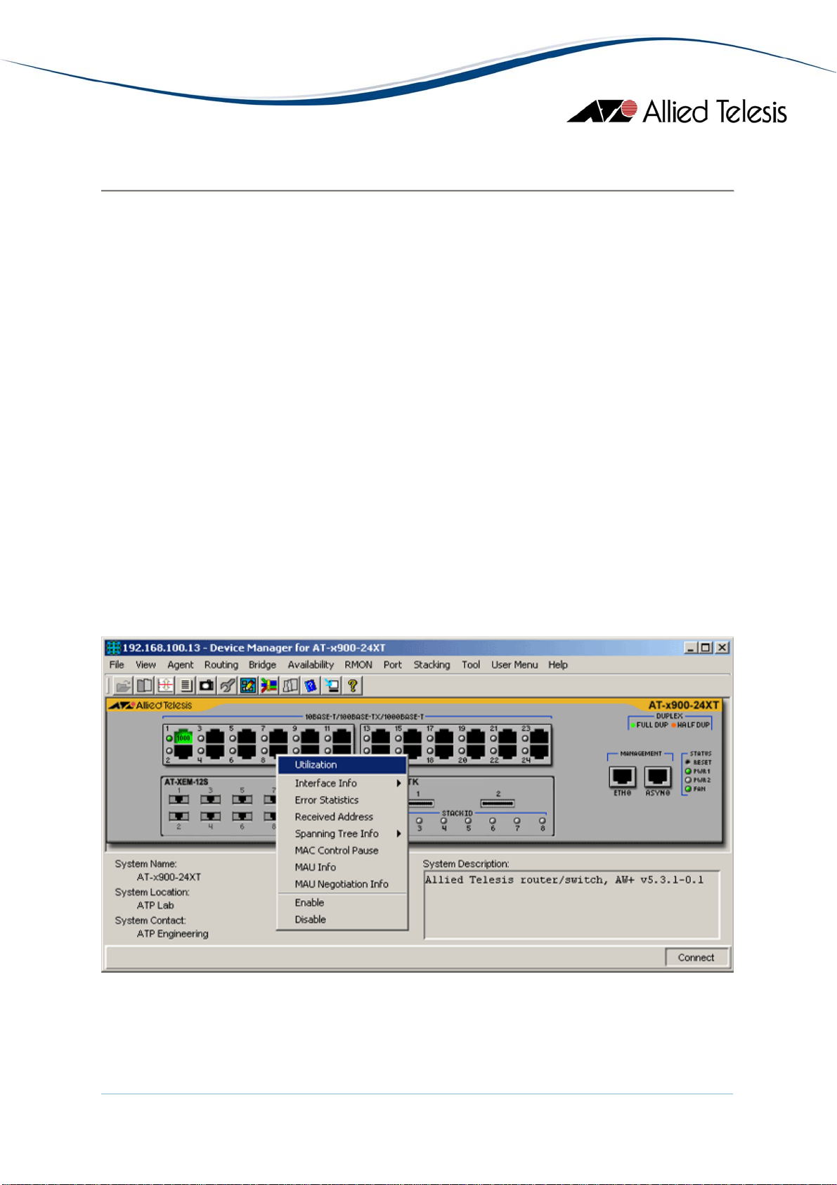
Device Manager's main window shows the main panel of the target device. It has both
common and device-specific menus on its menu bar.
Note - SNMPv3: All device-specific menu options are displayed regardless of the user's view
access security settings.
You can perform operations on the agent by doing a right click on the main panel or by
selecting a menu item from the menu bar. Ports and LEDs on the main panel indicate the
status of the port, system and traffic.
Topics:
• Common operations on the main window
• Menu for stacked devices
• Port selection dialog box
• Port status colors
• LED status
• Utilization
Common operations on the main window
Right clicking on a port
AlliedView™-EMS 4.0.1 Device Management Guide Page 9 of 411
Page 10
Port
Right clicking on a port opens a pull-down menu specific to the device. Selecting a
menu item opens another window and lets you view and edit MIB information
related to the port. You can also access the same menu from the menu bar.
RS-232 Terminal Port
Right clicking on an RS-232 port opens a pull-down menu and lets you choose how
to log into the agent. Depending on the managed device, choose Telnet or WEB
Browser.
Reset Button
Right clicking on a reset button opens a pull-down menu with an option that allows
you to reset the device. (Not available on some devices.)
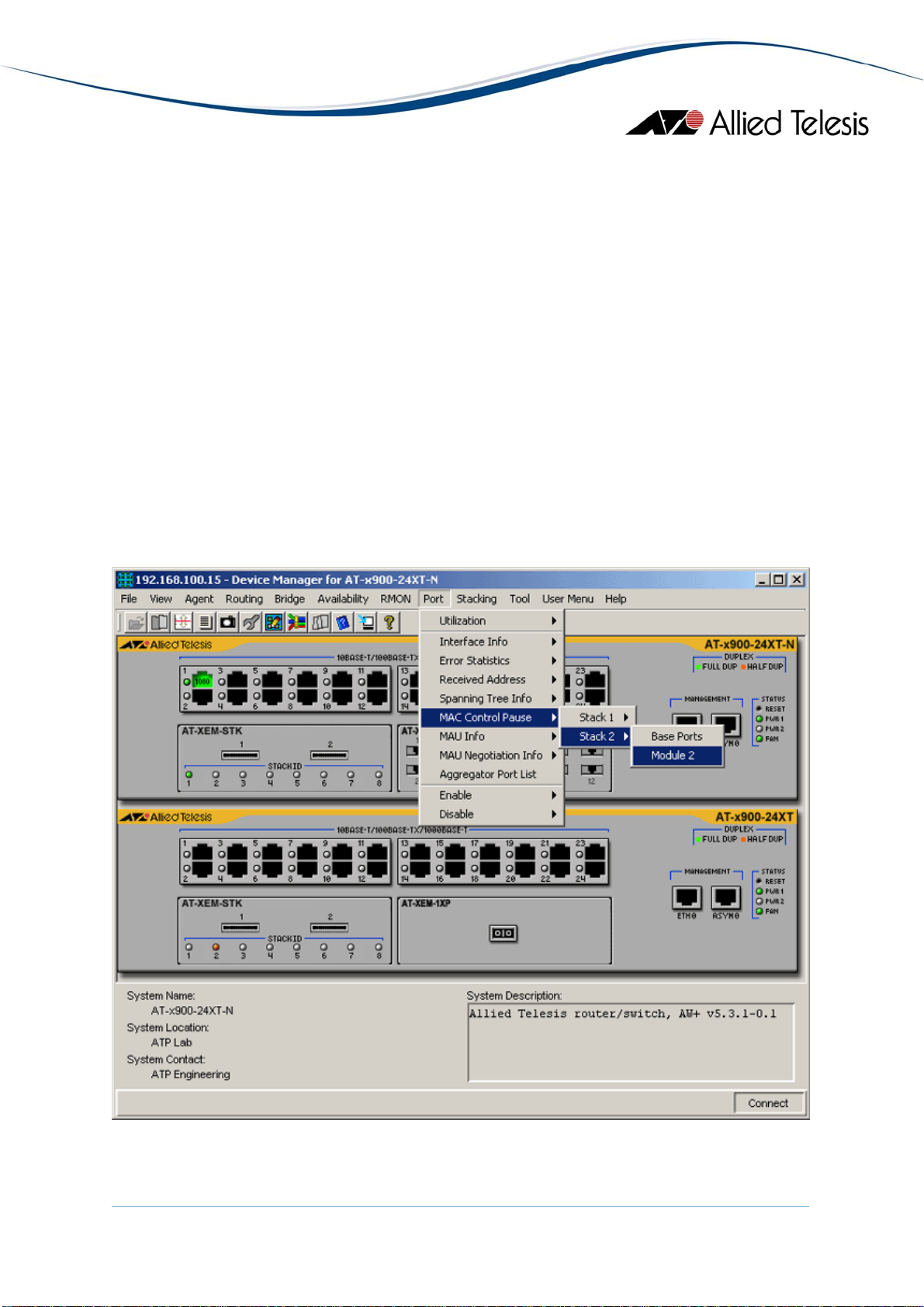
Menu for stacked devices
If the target is a stacked device, some menus have extra subitems to specify a single device
in the stack.
Module submenu
AlliedView™-EMS 4.0.1 Device Management Guide Page 10 of 411
Page 11
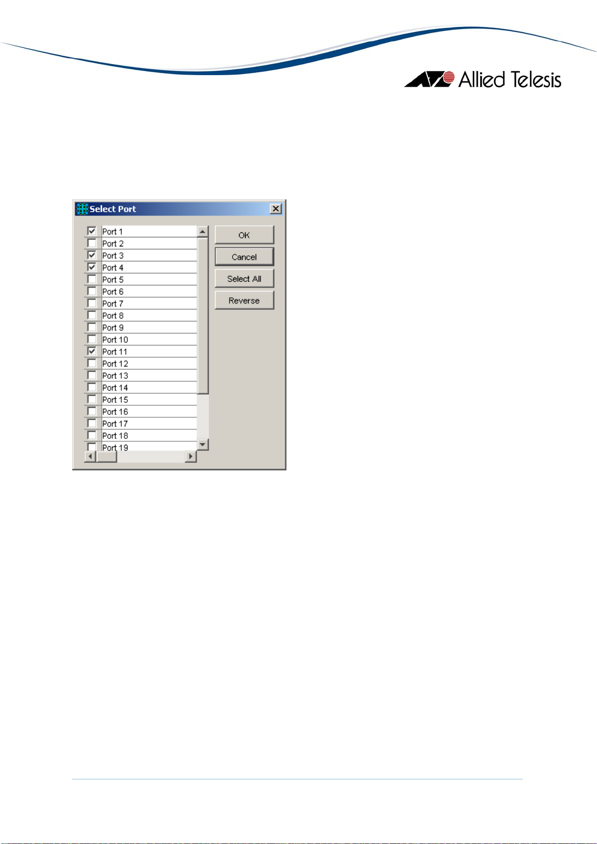
Port selection dialog box
When you select a menu item acting on ports, a dialog box opens to let you select ports.
Check the target ports and click OK.
Note - If you select multiple ports, it may take some time for data to be displayed.
Select Port dialog box
Port status colors
Port status is shown by its color. Port speed is also displayed in the port image.
• Link Up: Green
• Disabled: Red (the port is disabled by an administrator)
• Partitioned/Blocking: Yellow
• Others: Default colour (usually black)
Note - SNMPv3: Depending on the READ VIEW access settings of the User Account Name
used, there is a possibility that Device Manager may not be able to access some MIB values
that control the Port status. When this happens, the affected ports will be shown in the
default color.
LED status
In Device Manager, LEDs do not blink. The meaning of each LED will differ from one device
to another.
AlliedView™-EMS 4.0.1 Device Management Guide Page 11 of 411
Page 12

Utilization
Utilization is calculated by the following formula.
# of frames x (96 + 64) + octets x 8
Utilization (%) = ------------------------------------------- x 100
Port speed (bps) x Sampling Interval(sec)
Basic Operations
AlliedView™-EMS 4.0.1 Device Management Guide Page 12 of 411
Page 13
Layer 2 Switches
AT-8000 Series
This section describes Device Manager menus and operations specific to the AT-8000
Series.
Topics:
• Main Window
• Agent Menu
• Bridge Menu
• RMON Menu
• Port Menu
• Stacking Menu
• Expansion Module Notes
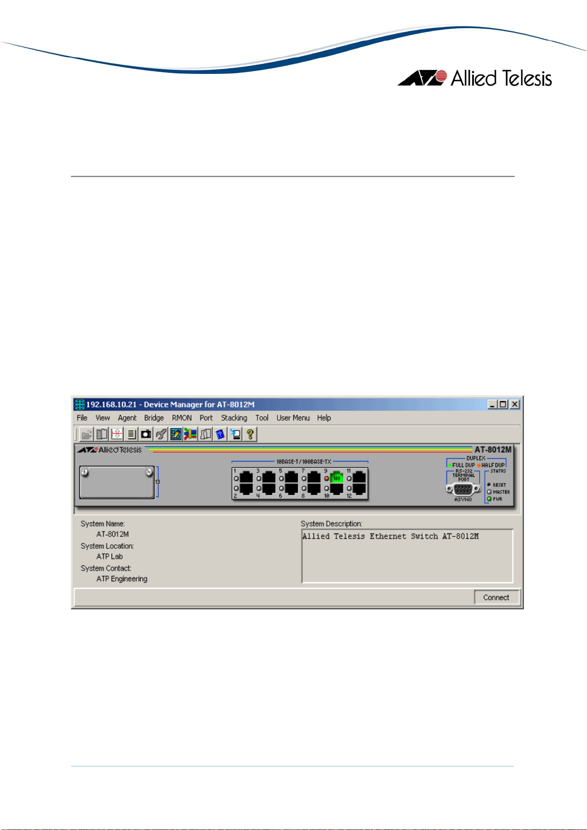
Main Window
AT-8012M
AlliedView™-EMS 4.0.1 Device Management Guide Page 13 of 411
Page 14
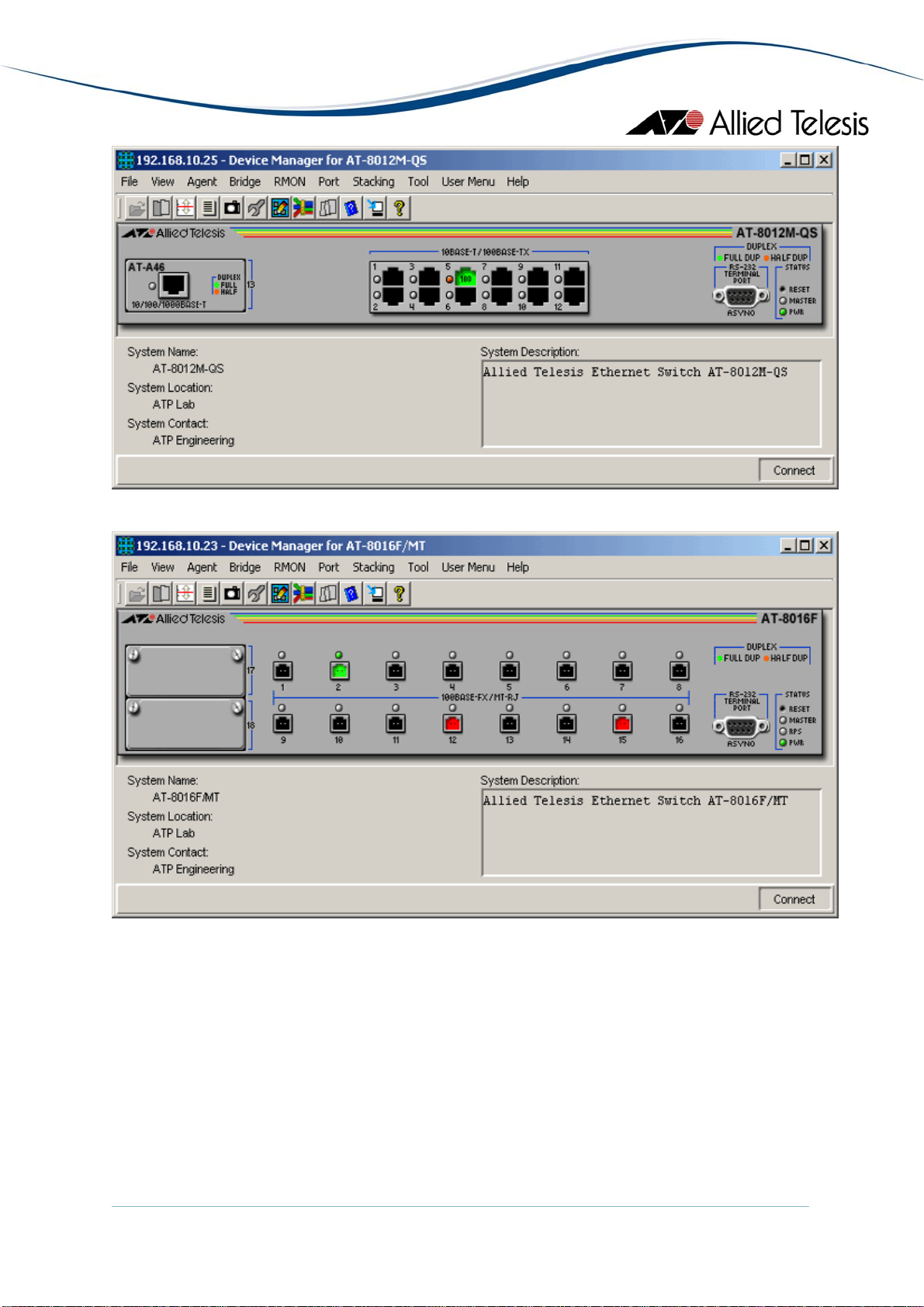
AT-8012M-QS
AT-8016F/MT
AlliedView™-EMS 4.0.1 Device Management Guide Page 14 of 411
Page 15
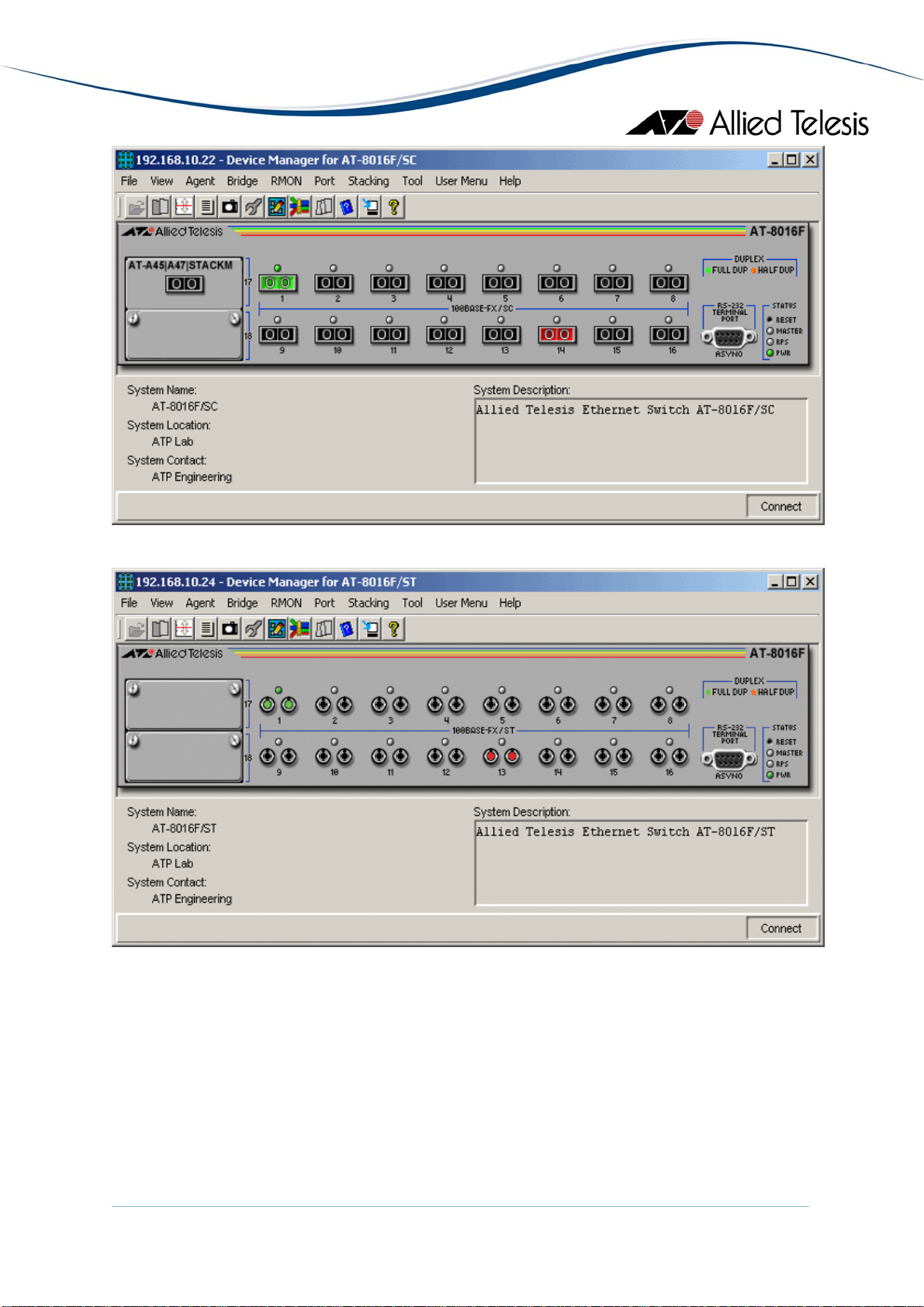
AT-8016F/SC
AT-8016F/ST
AlliedView™-EMS 4.0.1 Device Management Guide Page 15 of 411
Page 16
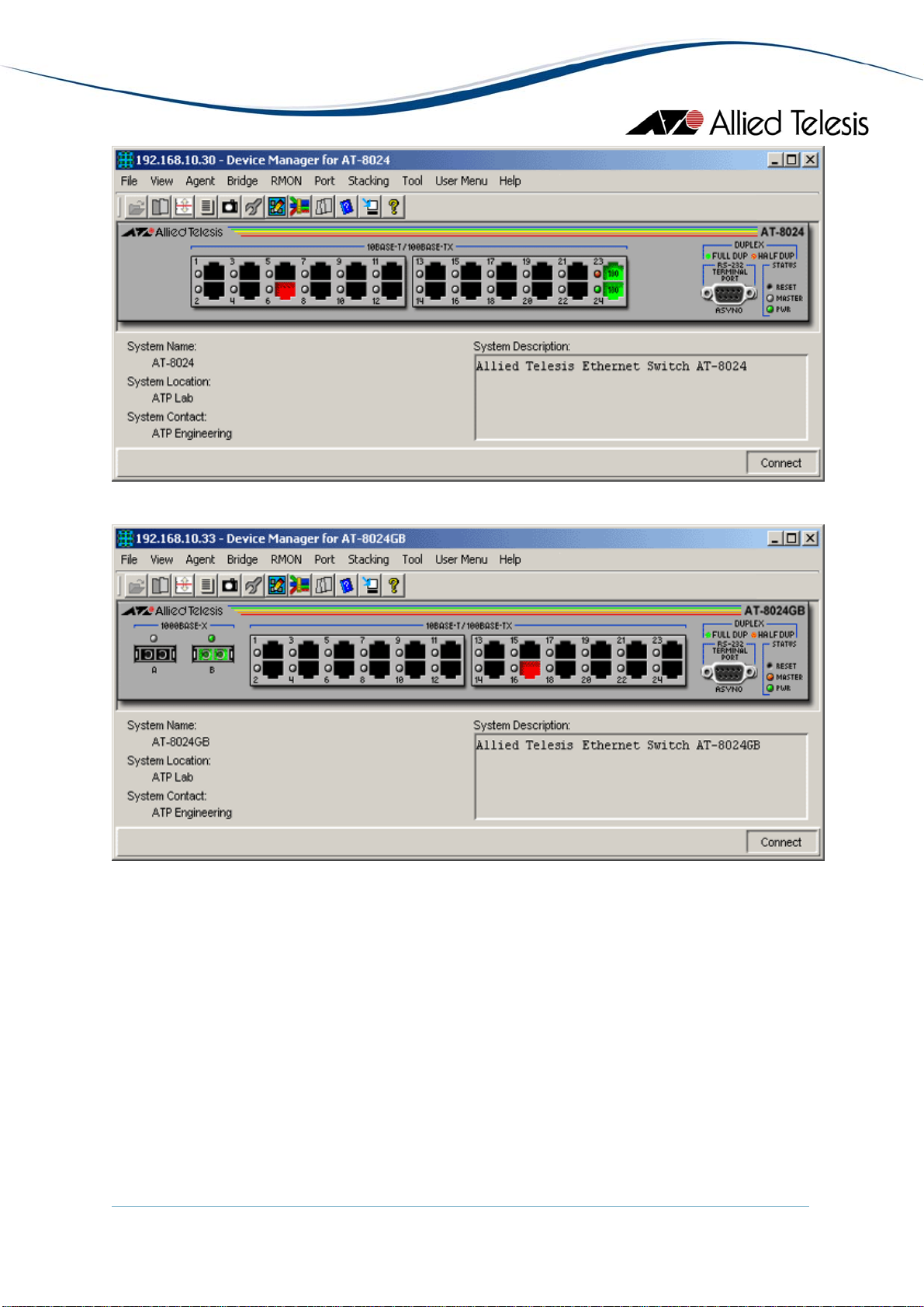
AT-8024
AT-8024GB
AlliedView™-EMS 4.0.1 Device Management Guide Page 16 of 411
Page 17
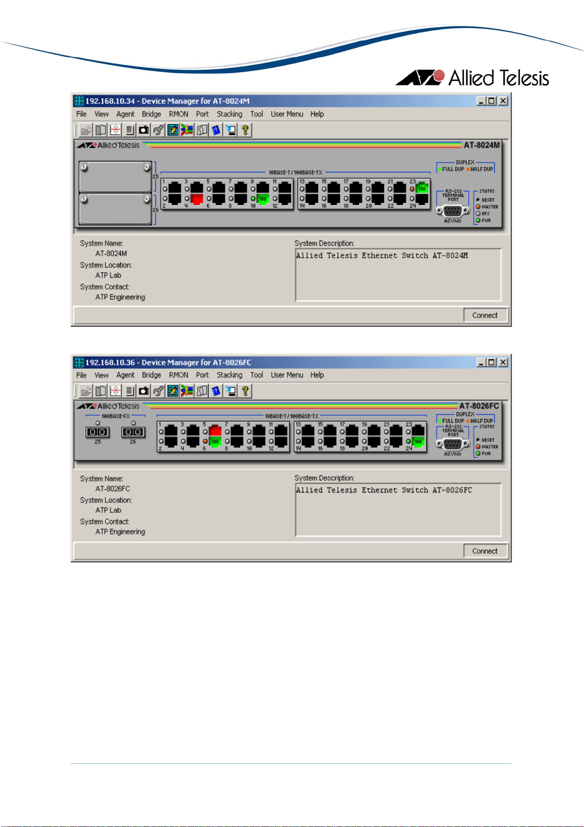
AT-8024M
AT-8026FC
AlliedView™-EMS 4.0.1 Device Management Guide Page 17 of 411
Page 18
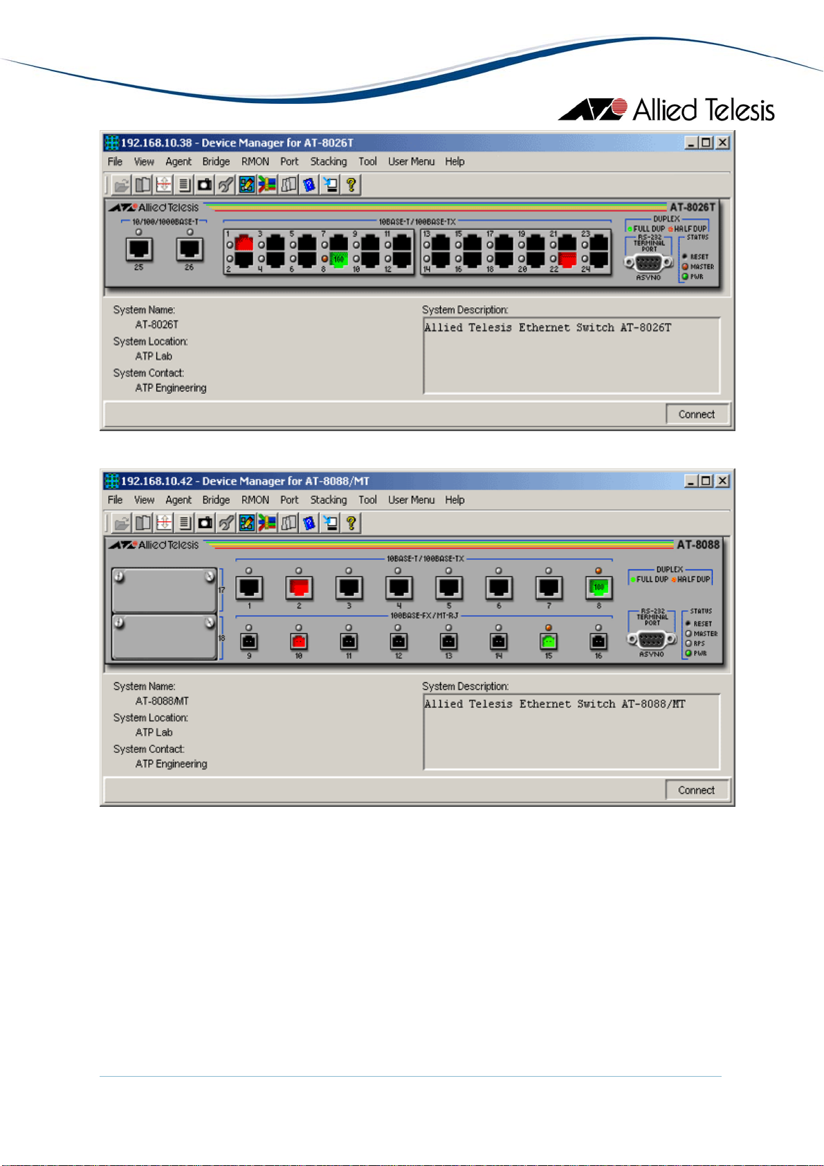
AT-8026T
AT-8088/MT
AlliedView™-EMS 4.0.1 Device Management Guide Page 18 of 411
Page 19
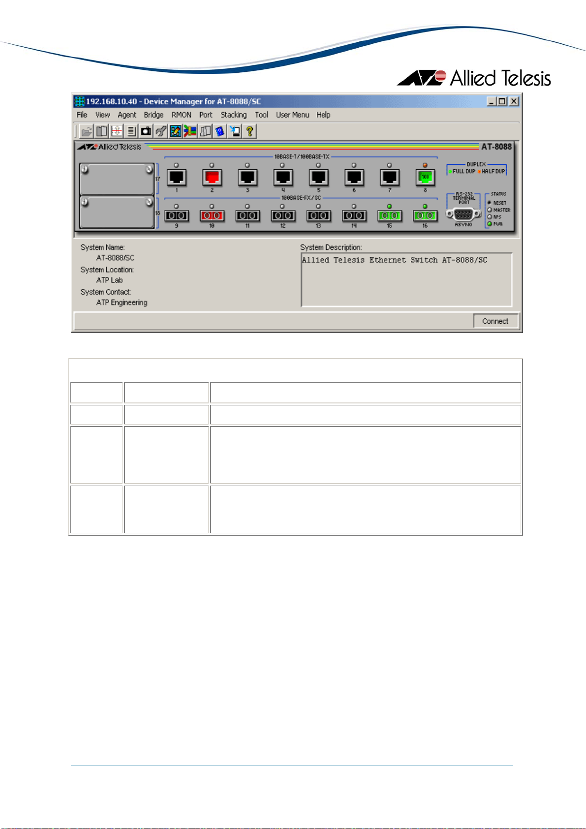
AT-8088/SC
Device Manager LEDs for AT-8000 Series
LED State Description
PWR Green The switch is receiving power.
MASTER Orange
The switch is the master switch of an enhanced stack.
Gray
The switch is a slave switch or is not a member of an enhanced
stack.
DUPLEX Green
Orange
The port is operating in full-duplex mode.
The port is operating in half-duplex mode.
Note - Please refer to Uplink Modules for the operations and behavior of the expansion
modules installed on these devices.
Note - The current firmware version does not allow Device Manager to support the RPS
LED.
Note - When connecting to a slave switch, Device Manager does not automatically replace
the master switch image in the main window with the slave switch image. To view the slave
switch image, click on the Refresh option under the Agent menu.
Note - Device Manager will detect a loss of connection between an AT-8024GB and an AT-
9410GB when the uplink port on both devices are set to the same speed and mode.
Note - Connection between an AT-8024GB and an AT-8324 can only be established if the
uplink ports on both devices are configured to auto-negotiate.
AlliedView™-EMS 4.0.1 Device Management Guide Page 19 of 411
Page 20

Note - Setting the 'Active Protocol Version' to 'STP' and 'Spanning Tree Status' to 'enabled'
will set the Port State parameter of disabled ports to 'blocking'. As a result, port images for
disabled ports will turn yellow.
Note - Setting the 'Active Protocol Version' to 'RSTP' and 'Spanning Tree Status' to 'enabled'
will set the Port State parameter of inactive ports and disabled ports to 'blocking'. As a
result, port images for inactive ports and disabled ports will turn yellow.
Agent Menu
From the Agent menu, you can view and edit the system information for the device, or log
into the CLI using Telnet.
System Info
Displays basic system information, including system name, location, contact and
description.
Note - Attempting to set the System Contact, System Name, and System Location
parameters to NULL will result in a general error. However, the parameters will still
be temporarily set to NULL. Once the switch is restarted, the original values will be
restored.
Note - The current firmware version accepts up to 40 characters for the System
Contact, System Name and System Location parameters. However, specifying a
value that is exactly 40 characters in length will result in an error message. This
error message may be ignored as the value will still be set successfully.
Firmware Info
Displays firmware version.
Network Info
Displays network-related information such as the addresses of the default gateway
and the agents.
Note - The current firmware version does not allow the Default Domain Name and
the DNS Server parameters to be configured.
Manager Address Info
Displays the IP address of the management station.
Device Info
Displays general information about the switch.
MAC Address Table
Displays a list of static MAC addresses configured on the switch.
AlliedView™-EMS 4.0.1 Device Management Guide Page 20 of 411
Page 21

Note - MAC Address Table entries created through a local or telnet management
session will not be visible to Device Manager until the device is restarted.
Reset
Resets the switch.
Telnet
Starts a Telnet connection to the switch.
WEB Browser
Connects to the switch's HTTP server.
Bridge Menu
From the Bridge menu, you can view and edit bridge information such as the forwarding
database and the spanning tree status.
Forwarding Database
Note - AT-8016F/xx: The current firmware version may, at times, return duplicate
Forwarding Database table entries.
Standard View
Displays the Forwarding Database table as returned by the device.
Enhanced View
Displays the Forwarding Database table on a per port basis. User can select a port
or group of ports to view its corresponding Forwarding Database entries.
Discard/Aging Time Info
Displays information about the number of address entries that were learned but
discarded because either there was a lack of memory or the entry's aging timer
expired.
Note - The current firmware version accepts values in the range [10-1000000]
inclusive for the Aging Time parameter.
Spanning Tree Info
Displays spanning tree parameters such as priority and cost.
Note - The current firmware version accepts values in the range [0-65535] inclusive
for the Priority parameter regardless of the active spanning tree protocol version.
Statistics
Displays statistics about frames received/transmitted on the switch port.
AlliedView™-EMS 4.0.1 Device Management Guide Page 21 of 411
Page 22

RMON Menu
From the RMON menu you can view and edit the RMON MIB.
Statistics
Displays traffic statistics in the network segment attached to each port.
History Control Table
Displays the RMON History table.
Note - The current firmware version does not support the "historyControlTable"
MIB object of RFC1757. As a result, Device Manager displays the error message
"Failed to get MIB data." when the History Control Table option is selected from the
RMON menu.
Alarm Table
Displays the RMON Alarm table.
Event Table
Displays the RMON Event table.
Event Log
Displays the RMON Event log.
Port Menu
From the Port menu, you can view and edit MIB information about the port.
Utilization
Displays the port's utilization information.
Interface Info
Displays port statistics such as the number of frames received and transmitted on
the port, bytes received and transmitted on the port, and port status.
Note - Valid MIB Set values for the Administration Status parameter are 'up' and
'down'. Attempting to set this parameter to any other value will result in the error
message: "The error occurred with 'Set' operation. Error: bad value."
Error Statistics
Displays error statistics.
Detail Info
Displays detailed port information such as duplex mode.
AlliedView™-EMS 4.0.1 Device Management Guide Page 22 of 411
Page 23

Note - Valid MIB Set values for the Port Flow Control parameter are 'disable',
'transmit-only', 'receive-only', and 'transmit-and-receive'. However, the current
firmware version does not allow this parameter to be set to 'transmit-only' and
'receive-only' for the following ports:
• Expansion module ports
• GBIC ports on the AT-8024GB
• Fiber optic ports on the AT-8026FC
Note - Valid MIB Set values for the Port State parameter are 'enabled' and 'disabled'.
Attempting to set this parameter to any other value will result in the error message:
"The error occurred with 'Set' operation. Error: bad value."
Note - The current firmware version accepts up to 20 characters for the Port Name
parameter. Attempting to enter more than 20 characters will result in an error
message and may append additional characters to the input value.
Spanning Tree Info
Displays the port's spanning tree parameters.
Note - Setting a port's Port parameter to 'disabled' does not automatically set the
Port State parameter under Detail Info to 'disabled'. As a result, the port's image
may not turn red as expected.
Note - The current firmware version accepts values in the range [0-255] inclusive for
the Port Priority parameter regardless of the active spanning tree protocol version.
Note - The current firmware version accepts values in the range [0-65535] inclusive
for the Port Path Cost parameter regardless of the active spanning tree protocol
version.
Enable
Enables the port.
Note - Under the Sun Solaris platform, the Device Manager application may
terminate abnormally if multiple ports have been selected and each dialog box with
the message "May I set 'atiswitchPortState.n' to up" is clicked one after the other.
Disable
Disables the port.
Note - Under the Sun Solaris platform, the Device Manager application may
terminate abnormally if multiple ports have been selected and each dialog box with
the message "May I set 'atiswitchPortState.n' to down" is clicked one after the other.
Port Mirroring
Displays port mirroring parameters and allows configuration of port mirroring state,
source, and destination.
AlliedView™-EMS 4.0.1 Device Management Guide Page 23 of 411
Page 24

Note - Valid MIB Set values for the Mirroring Destination Port parameter should
range from 0 to 24. However, the current firmware version allows the user to enter
values up to 65535. Attempting to enter values greater than 65535 will cause the
new value to be converted to its equivalent wrap-around value; i.e., 65536 will
become 0, 65537 will become 1, and so on.
Note - The current firmware version does not allow the Port Mirroring Status
parameter to be set to 'receive' and 'transmit'. Attempting to do so will result in the
error message: "The error occurred with 'Set' operation. Error: bad value".
Note - By default, the Port Mirroring Status parameter is set to 'disabled' and the
Mirroring Destination Port parameter is set to 0. From this default state, the Port
Mirroring Status parameter can be set to 'both' successfully. However, to set the
Port Mirroring Status parameter back to 'disabled', the Mirroring Destination Port
parameter must be set to a non-zero value.
Note - Any change made to the Mirroring Source Ports parameter while the
Mirroring Destination Port parameter is set to 0 will take effect internally but will
not be reflected in the MIB variable window. To see the change reflected in the MIB
variable window, the Mirroring Destination Port parameter should be set to a nonzero value.
Stacking Menu
From the Stacking menu, you can perform enhanced stacking from any AT-8000 Series
master switch.
Stacking Info
Displays information about the switch's mode. This is also the menu where you can
perform enhanced stacking.
Note - For the Stack Switch Model parameter, additional characters appear after the
model name for discovered AT-8524M, AT-9424T/SP and AT-9424T/GB devices.
Expansion Module Notes
• Device Manager cannot distinguish between the AT-A45/xx, AT-A47,
and AT-STACKM expansion modules. All are displayed with the same GIF image.
• When both the AT-A45 and AT-A46 expansion modules are present on a device,
the AT-A45 port image may show up as green and its Port Speed parameter may
reflect the value "1 Gbps" even if there is no connection established on the port. To
reflect the correct port image color and port speed, restart the device. This applies
to the following devices:
AlliedView™-EMS 4.0.1 Device Management Guide Page 24 of 411
Page 25

AT-8016F/xx
AT-8024M
AT-8088/xx
• The Spanning Tree Protocol (STP) does not work for the AT-A46 expansion module
when it is installed on an AT-8016F/ST device. As a result, the Port State parameter
of the AT-A46 expansion module port will never be set to 'blocking' and the port
image will never turn yellow.
• Connection between an AT-A47 expansion module port that is configured to
operate at 1Gbps full duplex and a port on another device can only be established if
the port on the other device is configured to auto-negotiate.
• For the AT-A47 expansion module, Device Manager will only display the AT-
A45/AT-A47/AT-STACKM shared GIF image if a GBIC module is present in the
GBIC slot.
• By default, the Port Speed and Mode parameter of the AT-A47 expansion module
port is set to 'auto sense'. From this mode, the Port Speed and Mode can only be
changed to '1Gbps full-duplex'. However, once set to '1Gbps full-duplex', it can no
longer be set to 'auto sense'.
AT-8000 Series
AlliedView™-EMS 4.0.1 Device Management Guide Page 25 of 411
Page 26
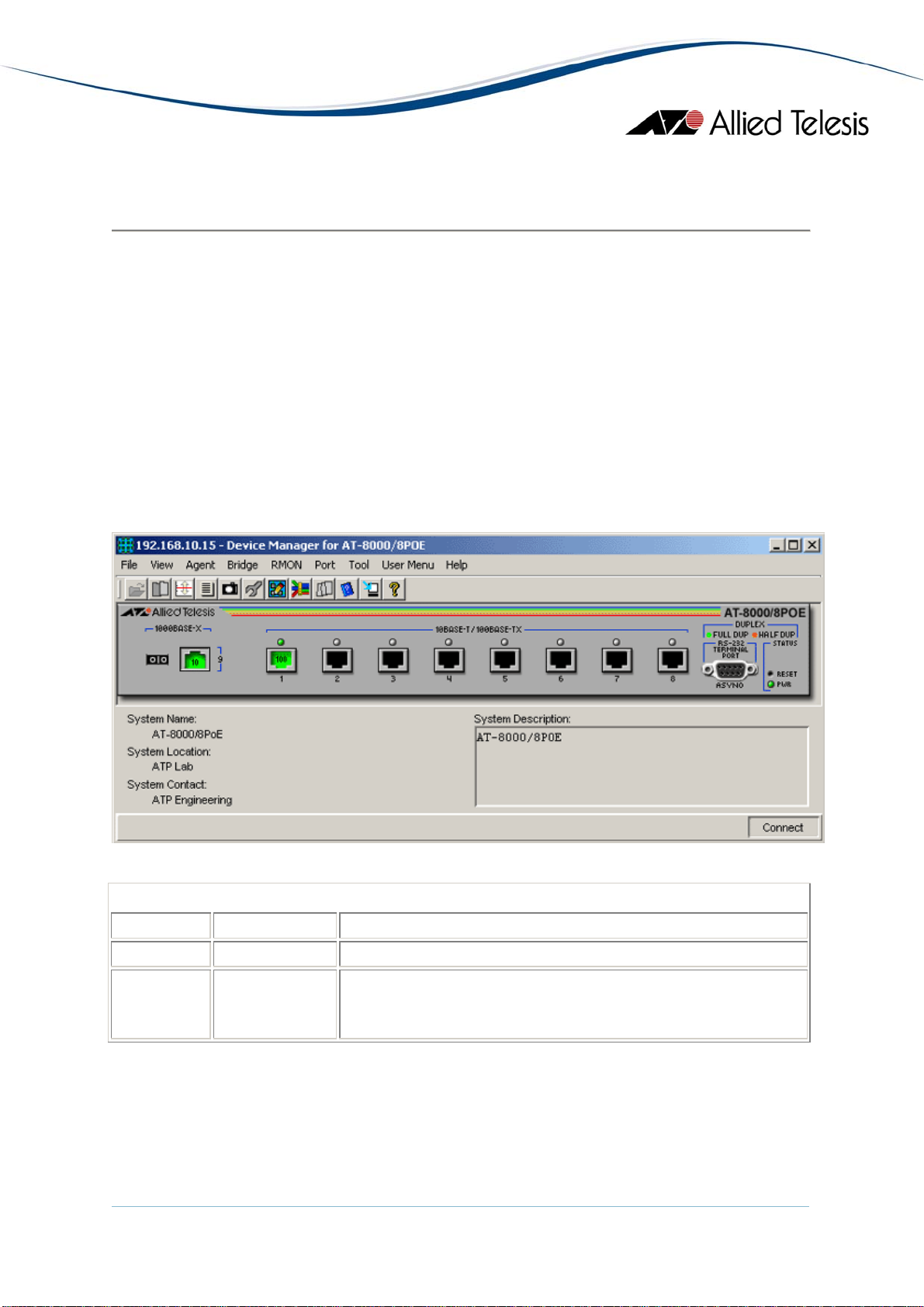
AT-8000/8POE
This section describes Device Manager menus and operations specific to the AT-8000/8POE
switch.
Topics:
• Main Window
• Agent Menu
• Bridge Menu
• RMON Menu
• Port Menu
Main Window
AT-8000/8POE
Device Manager LEDs for AT-8000/8POE
LED State Description
PWR Green The switch is receiving power.
DUPLEX Green
Orange
The port is operating at full-duplex mode.
The port is operating at half-duplex mode.
Note - The current firmware version does not allow Device Manager to determine whether
a port is enabled or disabled. As a result, port images will remain black even if they are
actually disabled.
Note - The current firmware version does not allow Device Manager to detect the presence
or absence of an SFP module in the SFP slot. As a result, the SFP slot on the device image
AlliedView™-EMS 4.0.1 Device Management Guide Page 26 of 411
Page 27

will always show an SFP image regardless of whether or not an SFP module is physically
present in the slot.
Note - Status information for port 9 will always be reflected on both the RJ-45 port image
nd the SFP port image regardless of whether it is the RJ-45 or the SFP port that is actually
a
in operation. However, if Device Manager detects that the established link speed is less tha
1Gbps, only the RJ-45 port image will turn green.
Note - When Global RSTP is enabled, the current fi
arameter of inactive ports to 'blocking'. As a result, expect port images for inactive ports
p
rmware version sets the Port State
to turn yellow in Device Manager.
Agent Menu
n
From the Agent men
u, you can view and edit the system information for the device, or log
into the CLI using Telnet.
System Info
Displays basic system information, including system name, location, contact and
ription.
desc
Note - The cu
rrent firmware version accepts anywhere from 1 up to 64 characters
for the System Contact, System Name and System Location parameters. NULL
values are not accepted.
Firmwar
e Info
Displays firmware version.
Networ
k Info
Displays network-related information such as the addresses of the default gateway
and th
e agents.
Manage
r Address Info
Displays the IP address of the management station.
Note - The current firmware version does not allow
Address parameters to be configured.
DHCP I
nfo
Displays DHCP information including the DHCP System Group and DHCP Timer
up.
Gro
Reset
Resets the switch.
Telnet
Starts a Telnet connection to the switch.
the Trap Destination IP
AlliedView™-EMS 4.0.1 Device Management Guide Page 27 of 411
Page 28

WEB Br
owser
Connects to the switch's HTTP server.
Bridg
e Menu
From the Bridge men
status.
Forward
ing Database
Displays the Forwarding Database table as returned by the device.
Discard
/Aging Time Info
Displays information about the device's aging time.
Spannin
g Tree Info
Displays spanning tree parameters such as priority and cost.
Note - Values entered for the Root Maximum Aging Time, Ro
Root Forward Delay Time parameters must be multiples of 100. Values that are not
multiples of 100 will be automatically rounded down to the nearest hundreds.
Statistic
s
Displays statistics about frames received/transmitted on the switch's ports.
Basic Br
idge Info
Displays basic bridge information such as the LAN ID, bridge address, number of
ports and
the bridge type.
Bridge P
ort Info
Displays basic bridge information on a per port basis such as the LAN ID, port
number,
circuit, delay exceeded discards and MTU exceeded discards.
Note - The current firmware version returns a NULL value for the Circ
parameter.
u, you can view and edit bridge information such as the spanning tree
ot Hello Time and
uit
RMON Menu
From the RMON men
Statistics
Standard
isplays traffic statistics in the network segment attached to each port.
D
Note - To collect statistical data on an interface, do the following using a
browser tool that allows you to issue an SNMP Set request on a specific table
element:
AlliedView™-EMS 4.0.1 Device Management Guide Page 28 of 411
u you can view and edit the RMON MIB.
MIB
Page 29

• Set the etherStatsStatus (1.3.6.1.2.1.16.1.1.1.21) object to "createReque
• Set the etherStatsDataSource (1.3.6.1.2.1.16.1.1.1.2) object to the OID of
Eth
ernet interface to monitor (e.g. 1.3.6.1.2.1.2.2.1.1.1 - Port 1)
• Set the etherStatsStatus object to "valid(1)"
Additional Info
Displays additional traffic statistics in the network segment such as frame
received/sent, collisions, broadcast frames and mult
Note - The Def
8000/8POE and should be ignored.
Error
Displays error statistics in the network segment such as CRC errors, alignm
errors, bad frames received late coll
History Control Table
Displays the RMON History table.
Note - To maintain a history of statistics taken at particular intervals for an interface,
do the follow
request on a specific table element:
st(2)"
the
s
icast frames.
erred Transmissions parameter is not applicable to the AT-
ent
isions and total transmit errors.
ing using a MIB browser tool that allows you to issue an SNMP Set
• Set the historyControlStatus (1.3.6.1.2.1.16.2.1.1.7) object to
"createRequest(2)"
• Set the historyControlDataSourc
e (1.3.6.1.2.1.16.2.1.1.2) object to the OID of
the Ethernet interface for which historical data will be collected (e.g.
1.3.6.1.2.1.2.2.1.1.1 - Port 1)
tatus object to "valid(1)"
Alarm Table
• Set the historyControlS
Displays the RMON Alarm table.
Event Table
ays the RMON Event table.
Displ
ent Log
Ev
lays the RMON Event log.
Disp
ort Menu
P
From the Port menu, you can view and edit MIB information about the port.
Utilization
Displays the port's utilization information.
AlliedView™-EMS 4.0.1 Device Management Guide Page 29 of 411
Page 30

Interface Info
Standard
Displays port statistics such as the number of packets received and transmitted on
the po
Note - The current firmware version returns a NULL value for the Specific Media
MIB parameter.
Additional Info
Displays port sta
the port, bytes received and transmitted on the port and port status.
Note - The Deferred Transmissions parameter is not applicable to the AT-8000/8POE
and should be ignored.
Error Statistics
Displays error statistics.
Detail In
fo
Displays detailed port info
e - The current firmware version does not return the correct value for the Port
Not
State parameter. It also does not allow the parameter to
Note - The Port Flow Control and Port QoS Priority parameters are not applicable
to the AT-8000/8POE and should be ignored.
Spannin
g Tree Info
Displays the port's spanning tree parameters.
Enable
Enables the port.
Disable
Disables the port.
Port Mirr
oring
Displays port mirro
source and destination.
IGMP S
nooping
Displays the current stat
rt, bytes received and transmitted on the port and port status.
tistics such as the number of frames received and transmitted on
rmation such as duplex mode.
be configured.
ring parameters and allows configuration of port mirroring state,
e of IGMP Snooping and allows reconfiguration.
8000/8POE AT-
AlliedView™-EMS 4.0.1 Device Management Guide Page 30 of 411
Page 31

AT-8000GS Series
This section describes Device Manager menus and operations specific to the AT-8000GS Series.
Topics:
• Main Window
• Agent Menu
• Routing Menu
• Bridge Menu
• IGMP Menu
• Security Menu
• RMON Menu
• Port Menu
AlliedView™-EMS 4.0.1 Device Management Guide Page 31 of 411
Page 32

Main Window
AT-8000GS/24, AT-8000GS/24POE and AT-8000GS/48
The AT-8000GS/24, AT-8000GS/24POE and AT-8000GS/48 can be combined to form a
single stack of up to 6 units.
Device Manager LEDs for AT-8000GS Series
LED State Description
PWR Green The switch is receiving power.
STACK ID Orange
The stacked unit is either the Stacking Master or the Backup
Master.
Gray
The switch is a set to standalone mode.
Green
AlliedView™-EMS 4.0.1 Device Management Guide Page 32 of 411
The stacked unit is a slave switch.
Page 33

Device Manager LEDs for AT-8000GS Series
DUPLEX Green
Orange
The port is operating in full-duplex mode.
The port is operating in half-duplex mode.
Note - When multiple units of the AT-8000GS series are stacked together, port numbering
is continuous based on the Stack Number.
• Stack 1 - 1 to 50
• Stack 2 - 51 to 100
• Stack 3 - 101 to 150
• Stack 4 - 151 to 200
• Stack 5 - 201 to 250
• Stack 6 - 251 to 300
This numbering scheme assumes that a unit can have a maximum of 50 ports.
Note - The current firmware version does not allow Device Manager to detect the presence
of an SFP module in any of the SFP slots unless there is an active connection on the SFP
ports. As a result, SFP images will appear on the device panel only if there is an established
connection on the physical SFP ports.
Note - The current firmware version does not allow Device Manager to handle redundant
ports. As a result, the Duplex LED of the copper ports will remain green even if there is an
established connection on the equivalent SFP ports.
Agent Menu
From the Agent menu, you can view and edit the system information for the device, or log
into the CLI using Telnet.
System Info
Displays basic system information, including system name, location, contact and
description.
Note - Valid MIB Set values for the System Name parameter is up to 160 characters.
Note - The current firmware version allows the user to set System Name parameter
to NULL.
Device Info
General Info
Displays common management information.
Active Software File
Displays the currently available images on the flash.
AlliedView™-EMS 4.0.1 Device Management Guide Page 33 of 411
Page 34

Physical Description
Basic Info
Displays the number of stack units.
Module Info
Displays module information for each unit in the system.
Port Attributes
Displays port information.
Stack Info
Displays information about the stacked devices.
Stack Status
Displays the current unit ID and stack mode of the device after reset.
Note - The current firmware version does not allow Device Manager to
display the Current Unit ID parameter as a 'read-only' parameter for devices
configured in stacked mode.
Note - Valid MIB Set values for the Active Unit ID After Reset parameter is
[1-6] inclusive. However, the current firmware version allows the user to set
this parameter to '0'.
Power Supply Info
Displays information about the power supply.
Unit General Info
Displays the device's software versions.
Note - Configuring the Serial Number and Asset Tag parameters to any value
will cause the device to be inaccessible for approximately 1 minute.
Unit Environment Info
Displays the device's main power supply and temperature status.
Physical Sensors Info
Displays the device's sensor information.
Physical Entity
Displays the information about the device including the serial number.
Note - The current firmware version does not allow Device Manager to
display the Serial Number parameter as a 'read-only' parameter.
Note - Valid MIB Set values for the Physical Alias parameter should range
from 0 to 32. However, the current firmware version allows the user to
enter up to 6 characters only.
AlliedView™-EMS 4.0.1 Device Management Guide Page 34 of 411
Page 35

Note - Valid MIB Set values for the Physical Asset ID parameter should range
from 0 to 32. However, the current firmware version allows the user to
enter up to 16 characters only.
POE Info
MCU Info
Displays POE device's Microcontroller information.
POE Config
Displays POE device's configurations.
Note - AT-8000GS/24POE: When multiple units of the AT-8000GS series are
stacked together, the current firmware version does not allow the Maximum
PSE Power parameter to be configured to 'none' if the Unit ID of the device
is '3', '4', '5' or '6'.
Software Packages
Displays the device's software packages.
Management Info
General Management
Displays common management information.
Note - The current firmware does not allow the Reboot Delay parameter to be
configured.
Flash File System
Basic Info
Displays the flash file size of the device.
File List
Displays the device's list of files.
File Copy Info
Displays the device's file copy events.
Jumbo Frames
Displays the current jumbo frames status.
Management ACL
Basic Info
Displays basic information about the management access list.
Access Lists
Displays information about access lists.
AlliedView™-EMS 4.0.1 Device Management Guide Page 35 of 411
Page 36

Mid-level Management
Alarm Options
Displays information about alarm options.
Note - The current firmware version does not allow Alarm Enabling
parameter to be configured. Attempting to configure this parameter to any
valid value will result in the error "The error occurred with 'Set' operation.
Error: noSuchName.".
Note - The current firmware version does not allow Row Status parameter
to be configured. Attempting to configure this parameter to any valid value
will result in the error "The error occurred with 'Set' operation. Error: gen
Error.".
MIB Tree
Displays information about the device's MIB tree.
Tuning
Agent Diagnostics
Displays diagnostic information about the agent.
Note - The Location parameter is not applicable to the AT-8000GS series
and should be ignored.
General Tuning
Displays general tuning information.
Note - Valid MIB Set values for the Debug Level parameter should range from
1-100. However, the current firmware version allows the user to enter
values in the range 0-255.
Note - The current firmware version returns inconsistent values when
configuring High Priority and Low Priority parameters.
Max Entries Tuning
Displays information about the maximum entries in tuning.
TCP Tuning
Displays the memory pool size for Transmission Control Protocol tuning.
Radius Tuning
Displays the memory pool size for radius tuning.
Syslog Tuning
Displays the current cache size and its size after reset.
Management ACL Tuning
Displays the current number of access rules and the number after reset.
AlliedView™-EMS 4.0.1 Device Management Guide Page 36 of 411
Page 37

SSH Tuning
Displays the current number of the maximum number of authorized keys and
its value after reset.
Terminal Sessions
Displays the current number of maximum sessions and its value after reset.
DNS Client Tuning
Displays the maximum values of the cache entries and the negative cache
entries before and after reset.
Tuning Parameters
Displays the current value, value after reset, default value, minimum and
maximum value of the different tuning parameters.
Host Parameters
Displays the corresponding value of the different host parameters.
Terminal Debug Mode
Displays the terminal debug mode password.
Note - The current firmware does not allow the Terminal Debug Mode Password
parameter to be configured.
Telnet
Basic Info
Displays the basic telnet information.
Note - The current firmware does not allow the Password parameter to be
configured.
Telnet Sessions
Displays the login time, client ip address and telnet session status.
CLI Info
Displays information if the file is enabled or not.
Note - The current firmware does not allow the Password parameter to be
configured.
Note - The current firmware version does not allow Device Manager to
handle 'TruthValues' for the File Enable After Reset parameter. As a result,
Device Manager will display integer values of '1' and '2' instead of the value
'True' or 'False' for this parameter.
AlliedView™-EMS 4.0.1 Device Management Guide Page 37 of 411
Page 38

LCLI Info
Displays information about the device's Telnet sessions and SSH sessions if
enabled or not.
Note - Valid MIB Set values for the History Size and SSH History Size
parameters should range from 10-206 and 10-210 respectively. However, the
current firmware version allows the user to enter values up to 246.
Note - Valid MIB Set values for the Telnet History Size parameter is [10-206]
inclusive. However, the current firmware version allows the user to enter
values up to 246.
RS-232
Displays the configuration of the baud rate of the device.
Web
Displays the configuration about the HTTP and HTTPS Port the device used.
Note - The current firmware version does not allow the following parameters to be
configured:
Date and Time
Time Synchronization
Displays the configuration about the device's date/time and time zone.
Note - Valid MIB Set values for the DST Offset parameter should range from 1-1440.
However, the current firmware version allows the user to enter values outside of
the valid range and negative values as well.
Idle Timeout
HTTP Port
HTTP Enable
HTTPS Port
HTTPS Enable
HTTPS Active Certificate ID
Max HTTP Idle Timeout
Service Protocol
Attempting to configure these parameters to any valid value will result in the
error "The error occurred with 'Set' operation.Error:gen Error.".
Note - The current firmware version does not allow the Service Port, Service
Certificate and Service Max Idle Timeout parameters to be set to '0', '1000'
and '932160' values respectively.
Note - Valid MIB Set values for the Service Certificate ID parameter is [0-
1000] inclusive. However, the current firmware version allows the user to
enter '-1' and '1001' as its value.
AlliedView™-EMS 4.0.1 Device Management Guide Page 38 of 411
Page 39

Note - The current firmware version does not allow DST Start and DST End
parameters to be configured when the DST Mode is set to 'recurring' or 'date' value.
Note - The current firmware version does not allow Device Manager to display the
Managed Time parameter in a 12hour format.
Note - Valid MIB Set values for the Time Zone Code and DST Code parameters are
up to 4 characters. However, the current firmware version allows the user to enter
up to 16 characters.
SNTP/NTP Client Config
Displays information about SNTP/NTP client configuration.
Note - Valid MIB Set values for the Polling Interval parameter should range from 60-
86400. However, the current firmware version allows the user to enter values
outside of the valid range and negative values as well.
SNTP Config
Displays information about SNTP client configuration.
Broadcast Mode
Displays information about broadcast mode per interface.
SNTP Server Info
Displays information about trusted SNTP servers to be queried in unicast or
broadcast mode.
Note - Valid MIB Set values for the Key Identifier parameter is [1-4294967295]
inclusive. However, the current firmware version allows the user to enter the value
'0'.
Authentication Keys
Displays information about keys information for authentication of NTP packets.
Note - The Key ID parameter is implemented as 'read-only'.
System Log
Basic Info
Displays information and configuration of the device's log files.
Note - The current firmware version does not allow Clear Log File and Clear Cache
parameters to be configured.
Event Log
Displays information about events sent to the system log file.
AlliedView™-EMS 4.0.1 Device Management Guide Page 39 of 411
Page 40

Error Log
Displays information about errors registered to the system cache.
Syslog Device
Displays information about Syslog diagnostic messages.
Note - The current firmware version does not allow the Syslog Device Control
parameter to be configured.
Syslog Collector
Displays the information to generate syslog messages to an aggregating agent or
collector.
Syslog Application
Displays information about a managed entity that provides individual control over
the severity level of the messages that it will generate.
Note - The current firmware version does not allow Severity parameter to be
configured.
Reset
Resets the switch.
Telnet
Starts a Telnet connection to the switch.
WEB Browser
Connects to the switch's HTTP server.
Routing Menu
From the Routing menu, you can view and edit information about the switch's routing
functions.
IP
ARP Table
Displays the Address Resolution Protocol cache on the switch.
Note - The current firmware version does not allow Physical Address parameter to
be configured. Attempting to configure this parameter to any valid value will result in
the error "The error occurred with 'Set' operation. Error. bad value.".
Note - The current firmware version does not allow Mapping Type parameter to be
configured. Attempting to configure this parameter from 'static' to 'dynamic' value
will result in the error "The error occurred with 'Set' operation. Error. bad value.".
AlliedView™-EMS 4.0.1 Device Management Guide Page 40 of 411
Page 41

Note - The current firmware version does not allow Mapping Type parameter to be
set to 'invalid' or 'other' as its value.
Address Table
Standard
Displays the list of IP interfaces on the switch.
Additional Info
Displays additional information about the address table.
Note - The Backup Address parameter is not applicable to the AT-8000GS
series and should be ignored.
Note - The current firmware version does not allow the IP Interface Owner
parameter to be configured. Attempting to configure this parameter to any
valid value will result in the error "The error occurred with 'Set' operation.
Error. bad value.".
Note - Configuring the Port Number parameter will cause the device to be
inaccessible and may need the restarted.
Static Route Table
Displays the IP static routing table.
Note - The current firmware version does not allow Routing Type parameter to be
set to 'local' as its value.
Note - Configuring the Destination Metric and Next Hop AS Number parameters to
invalid values will automatically set the entered values to valid values.
IP Statistics
Displays statistics about IP routing, including the number of IP datagrams received.
Note - The current firmware version does not allow Forwarding Status parameter to
be configured. Attempting to configure this parameter to any valid value will result in
the error "The error occurred with 'Set' operation. Error. bad value.".
ARP Table Config
Displays configuration information about Address Resolution Protocol.
Note - The current firmware version does not allow Unresolve Timer parameter to
be configured. Attempting to configure this parameter to any valid value will result in
the error "The error occurred with 'Set' operation. Error. bad value.".
I/F Name-Address Translation
Displays information about the IP interface's name translated to an IP interface
address.
AlliedView™-EMS 4.0.1 Device Management Guide Page 41 of 411
Page 42

UDP
TCP
CIDR
TFTP
Displays configuration information about the TFTP.
Note - The current firmware version does not allow the Send Config File parameter
to be configured.
Note - Configuring the Get Config File parameter will cause the device to reboot and
reset its running configuration to default configuration.
Note - The current firmware version does not allow the File Server IP Address
parameter to be configured.
Note - Configuring the Retry Timeout and Total Timeout parameters to invalid
values will automatically set the entered values to valid values.
Listener Info
Displays User Datagram Protocol listener information.
UDP Statistics
Displays User Datagram Protocol statistics.
Connection Info
Displays Transmission Control Protocol connection-specific information.
Note - The current firmware version does not allow Connection Status parameter
to be configured. Attempting to configure this parameter to any valid value will
result in the error "The error occurred with 'Set' operation. Error: gen Error.".
TCP Statistics
Displays Transmission Control Protocol statistics.
Route Number
Displays the number of valid Classless Inter-Domain Routing entries.
Route Table
Displays the Classless Inter-Domain Routing routing tables.
Note - The current firmware version does not allow Routing Type parameter to be
configured. Attempting to configure this parameter to any valid value will result in
the error "The error occurred with 'Set' operation. Error. bad value.".
Note - The current firmware version does not allow the following parameters to be
configured:
Destination Port Number
AlliedView™-EMS 4.0.1 Device Management Guide Page 42 of 411
Page 43

Note - The current firmware version only allows the Routing Type parameter to be
set to 'reject' if the value prior to set operation is 'remote'.
ICMP
ICMP Statistics
Displays Internet Control Message Protocol Statistics.
Error Messages
Displays the variable that controls the ability to generate Internet Control Message
Protocol error messages.
DHCP Info
Basic Info
Displays DHCP information.
Snooping
Displays the system's DHCP Snoop information.
Note - The current firmware version does not allow the Clear Action parameter to
be set to 'noAction' as its value.
DNS Resolver
Resolver Config
Displays information about the Domain Name System client.
Note - The current firmware version does not allow the Reset parameter to be
configured to 'reset' as its value. Attempting to configure this parameter to any valid
value will result in the error "The error occurred with 'Set' operation. Error. bad
value.".
Basic Counters
Displays information about basic Domain Name System couters.
Counters by OpCode
Displays information about the current count of resolver queries and answers.
Counters by Response Code
Displays information about the current count of responses to resolver queries.
Lame Delegation Overflows
Displays information about number of times the resolver attempted to add an entry
to the lame delegation table.
Routing Protocol MIB
Destination Metric 2
Destination Metric 3
Destination Metric 4
Destination Metric 5
AlliedView™-EMS 4.0.1 Device Management Guide Page 43 of 411
Page 44

Cache Info
Displays information about a collection of objects providing access to and control of
a Domain Name System resolver's cache.
Negative Cache Info
Displays information about a collection of objects providing access to and control of
a Domain Name System resolver's negative response cache.
Additional Counters
Displays information about a collection of objects providing further instrumentation
applicable to many but not all Domain Name System resolvers.
Bridge Menu
From the Bridge menu, you can view and edit bridge information such as the forwarding
database and the spanning tree status.
Forwarding Database
Standard View
Displays the Forwarding Database table as returned by the device.
Enhanced View
Displays the Forwarding Database table on a per port basis. User can select a port
or group of ports to view its corresponding Forwarding Database entries.
Aging Time Info
Displays information about the device's aging time.
Spanning Tree Info
STP
Standard
Displays the spanning tree information such as the STP version and path cost.
Note - Valid MIB Set values for the Priority parameter is [0-65535] inclusive.
However, attempting to set this parameter to any value beyond 61440 will
result in the error "The error occurred with 'Set' operation. Error. bad
value.".
Additional Info
Displays additional Spanning Tree Protocol information like supported type.
Note - The current firmware version does not allow the Flood BPDU
Method parameter to be set to 'bridging' as its value.
Note - The current firmware version does not allow Device Manager to
handle 'TruthValues' for the STP Enable and Filter BPDU parameters. As a
AlliedView™-EMS 4.0.1 Device Management Guide Page 44 of 411
Page 45

MSTP
Statistics
Displays statistics about frames received/transmitted on the switch port.
Basic Bridge Info
Displays basic bridge information.
Bridge Port Info
Displays statistics about frames received/transmitted on the switch port.
Note - The current firmware version does not allow the Number of Traffic Class
parameter to be configured. Attempting to configure this parameter to any valid
value will result in the error "The error occurred with 'Set' operation. Error. bad
value.".
802.1p
Device Capabilities
Displays information on the device capabilities.
Port Priority Group
Displays information about the port priority.
Traffic Class
Displays information about the traffic class and traffic class priority.
Note - Valid MIB Set values for the Received Traffic Class parameter is [0-7]
inclusive. However, the current firmware version does not allow this parameter to
be set to 4-7 as its value.
MAC Table Info
Displays MAC table information.
Note - The current firmware version does not allow Device Manager to handle
'TruthValues' for the Trap Enable parameter. As a result, Device Manager will display
integer values of '1' and '2' instead of the value 'True' or 'False' for this parameter.
MAC Base Priority Support
Displays MAC Base priority support.
result, Device Manager will display integer values of '1' and '2' instead of the
value 'True' or 'False' for this parameter.
Basic Info
Displays the basic information about Multiple Spanning Tree Protocol.
Instance Info
Displays information that contains Multiple Spanning Tree Protocol instance
specific information for the Multiple Spanning Tree Protocol.
AlliedView™-EMS 4.0.1 Device Management Guide Page 45 of 411
Page 46

IGMP Menu
From the IGMP menu, you can view and edit Internet Group Management Protocol
information such as IGMP queries and reports sent between devices and interfaces on
which IGMP is enabled.
MAC Multicast Info
Displays configurations of the enabling/disabling multicast.
IGMP Config
Displays configurations of the Internet Group Management Protocol function.
Security Menu
From the Security menu, you can view and edit different security and authentication
protocols SSL, SSH, and port-based authentication.
Authentication/Authorization/Accounting
Basic Info
Displays basic information about Authentication/Authorization/Accounting.
Note - The current firmware version does not allow the EAP Current Method List
parameter to be configured. Attempting to configure this parameter to any valid
value will result in the error "The error occurred with 'Set' operation.Error: gen
error".
Method Lists
Displays information about all method lists.
Note - The current firmware version does not allow the Row Status parameter to be
set to 'create and go' or 'destroy' as its value.
Lines
Displays information about all lines, their passwords and their authorization levels.
Note - The current firmware version does not allow Row Status parameter to be
configured. Attempting to configure this parameter to any valid value will result in
the error "The error occurred with 'Set' operation. Error: gen Error".
Note - The current firmware version does not allow the following parameters to be
configured on the implemented data type and range:
Method List Name Level 1
Method List Name Level 2
Method List Name Level 3
Method List Name Level 4
Method List Name Level 5
AlliedView™-EMS 4.0.1 Device Management Guide Page 46 of 411
Page 47

Method List Name Level 6
Method List Name Level 7
Method List Name Level 8
Method List Name Level 9
Method List Name Level 10
Method List Name Level 11
Method List Name Level 12
Method List Name Level 13
Method List Name Level 14
Method List Name Level 15
As a result, it will display the values: 'enable_n_default', 'enable_c_default',
'login_n_default', 'login_c_default', 'http', 'https' and 'null' as valid values instead of
allowing the user to enter up to 20 characters for these parameters.
Note - The current firmware version does not allow the Password Valid Time
parameter to be configured.
Local Users
Displays information about all usernames, their passwords and their authorizations.
Note - The current firmware version does not allow the Password Valid Time
parameter to be configured.
Authenticated Users
Displays all the current users that have been authenticated.
EAP Method Lists
Displays information about all Extensible Authentication Protocol method lists.
Note - The current firmware version does not allow the Row Status parameter to be
set to 'create and go' or 'destroy' as its value.
Password Verification
Displays the system's password configurations.
Note - The current firmware version does not allow the Old Password, New
Password and Confirm Password parameters to be configured if the values for these
parameters were initially configured using CLI.
Port-based Authentication
PAE Port Info
Displays the system level information for each port supported by the Port Access
Entity.
Authenticator PAE Info
Displays configuration objects for the Authenticator Port Access Entity associated
with each port.
AlliedView™-EMS 4.0.1 Device Management Guide Page 47 of 411
Page 48

Note - The current firmware version does not allow Administrative Controlled
Directions parameter to be set to 'in' and Key Transmission Status parameter to
'true' as its value.
Authenticator PAE Statistics
Displays statistics objects for the Authenticator Port Access Entity associated with
each port.
Authenticator PAE Diagnostics
Displays diagnostics objects for the Authenticator Port Access Entity associated with
each port.
Authenticator PAE Session Statistics
Displays session statistics objects for the Authenticator Port Access Entity
associated with each port.
Note - The current firmware version returns a 'noSuchName' value for the following
parameters:
Received Octets
Transmitted Octets
Received Frames
Transmitted Frames
RADIUS
Note - The current firmware version does not allow Device Manager to display
values for the User Name parameter.
Basic Info
Displays basic RADIUS information.
RADIUS Server Info
Displays the IP address, User Datagram Protocol port number for authentication
and accounting request, and current status of the RADIUS server.
Note - The current firmware version does not allow Usage parameter to be set to
'wireless authentication' as its value.
Authentication Client Info
Displays the number of RADIUS Access-Response packets received from unknown
addresses and the identifier of the RADIUS authentication client.
Authentication Server Info
Displays the list of RADIUS authentication servers with which the client shares a
secret.
Accounting Client Info
AlliedView™-EMS 4.0.1 Device Management Guide Page 48 of 411
Page 49

Displays the number of RADIUS Access-Response packets received from unknown
addresses and the identifier of the RADIUS accounting client.
Accounting Server Info
Displays the list of RADIUS accounting servers with which the client shares a secret.
TACACS+
Basic Info
Displays basic TACACS+ information.
TACACS+ Server Info
Displays information about TACACS+ server.
Secure Shell
SSH Server
Displays information about the status of public key authentication and the type of
regenerated host key.
Note - Configuring the Regenerate Host Key parameter to 'rsa', 'dsa' or 'rsa1' values
will result to an error message "time out occurred." but the value is successfully set.
Moreover, after the set operation, attempting to view this table will display the
following 'read-only' parameters and should be ignored:
Server Host Public Key Algorithm
Server Host Public Key Fragment ID
Server Host Public Key Fragment Text
Server Host Public Key Fingerprint Algorithm
Server Host Public Key Fingerprint Algorithm
Server Host Public Key Fingerprint Digest Format
Server Host Public Key Fingerprint
Note - The current firmware version does not allow the Regenerate Host Key
parameter to be set to 'rsa1' as its value.
SSH Client
Displays information about the user name ssh client will use and the value of the
regenerated self key.
Note - Valid MIB Set values for the User Name parameter should range from 1-48.
However, the current firmware version allows the user to enter values in the range
0-160.
Note - The current firmware version does not allow the Regenerate Self Key
parameter to be set to 'rsa1' as its value.
Note - Configuring the Regenerate Self Key parameter to 'rsa' or 'dsa' as its value will
cause the device to be inaccessible and may need the restarted.
AlliedView™-EMS 4.0.1 Device Management Guide Page 49 of 411
Page 50

Secure Socket Layer
Basic Info
Displays basic SSL information.
Certificate Generation
Displays information about the generated keys and self signed certificates.
Note - The current firmware version does not allow the following parameters to be
configured:
Certificate Generation ID
Country Name
State or Province Name
Locality
Organization Name
Organization Unit Name
Common Name
Valid Days
RSA Key Length
Passphase
Attempting to configure these parameters to any valid value will result in the error
"The error occurred with 'Set' operation. Error: time out occurred.".
Note - The Certificate Generation Index parameter is implemented as 'read-only'.
Note - The current firmware version does not allow Action parameter to be
configured.
Export Certificate
Displays information about the saved data from Random Access Memory and flash.
Import Certificate
Displays information about the copied external certificate of the device.
Note - The current firmware version does not allow Fragment Text parameter to be
configured. Moreover, attempting to configure this parameter followed by Refresh
operation will display numeric values.
RMON Menu
From the RMON menu, you can view and edit the RMON MIB.
Statistics
Displays traffic statistics in the network segment attached to each port.
AlliedView™-EMS 4.0.1 Device Management Guide Page 50 of 411
Page 51

History Control Table
Displays the RMON History table.
Alarm Table
Displays the RMON Alarm table.
Event Table
Displays the RMON Event table.
Event Log
Displays the RMON Event log.
Port Menu
From the Port menu, you can view and edit MIB information about the port.
Utilization
Displays the port's utilization information.
Note - The current firmware version does not allow Device Manager to display the
Port Number parameter for single port.
Note - The current firmware version does not allow Device Manager to display
Utilization information.
Interface Info
Standard
Displays port statistics such as the number of frames received and transmitted on
the port, bytes received and transmitted on the port, and port status.
Note - The current firmware version returns a 'noSuchName' value for the following
parameters:
Transmitted Buffer Length
Received Unicast Packets (HC)
Received Multicast Packets (HC)
Received Broadcast Packets (HC)
Transmitted Unicast Packets (HC)
Transmitted Multicast Packets (HC)
Transmitted Broadcast Packets (HC)
Note - The current firmware version does not allow the Promiscuous Mode
parameter to be set to 'false' as its value.
Additional Info
Displays additional information about the port's interface info.
AlliedView™-EMS 4.0.1 Device Management Guide Page 51 of 411
Page 52

Test Interface
Displays port's test information.
Note - The current firmware version does not allow the Test Set Type parameter to
be configured. Attempting to configure this parameter to any valid value will result in
the error "The error occurred with 'Set' operation. Error. bad value.".
Error Statistics
Note - The Ethernet Chip Set parameter is not applicable to the AT-8000GS series
and should be ignored.
Note - The current firmware version returns a 'noSuchName' value for the following
parameters:
Alignment Error Frames
Multi Collision Frames
SQE Test Errors
Deferred Transmissions
Carrier Sense Errors
Symbol Errors
Detail Info
Displays detailed port information such as duplex mode.
Note - The Physical Address Type parameter is not applicable to the AT-8000GS
series and should be ignored.
Note - The current firmware version does not allow the following parameters to be
configured:
Attempting to configure these parameters to any valid value will result in the error
"The error occurred with 'Set' operation. Error. bad value." except for the Default
Priority parameter.
Note - The current firmware version does not allow the Host Mode parameter to be
set to 'multiple-auth' as its value.
Note - The current firmware version does not allow the Autonegotiation Capabilities
Config parameter to be configured. Attempting to configure this parameter to any
Tagged Mode
Default Priority
Row Status
Port Flow Control Config
Port Speed
Reactive and Combo Ethernet Config
AlliedView™-EMS 4.0.1 Device Management Guide Page 52 of 411
Page 53

valid value will result in the error "The error occurred with 'Set' operation. Error.
bad value.".
POE Port Status
Displays port's POE information.
Note - Valid MIB Set values for the Port Power Limit parameter is [0 - 2147483647].
However, the current firmware version does not allow this parameter to be
configured to any value. Attempting to configure this parameter from 154012147483647 will result in the error "The error occurred with 'Set' operation.Error:
gen error".
Spanning Tree Info
STP
Standard
Displays the port's spanning tree parameters.
Additional Info
Displays a list of information maintained by every port about the Spanning
Tree Protocol state for that port.
Note - The current firmware version does not allow Device Manager to
handle 'TruthValues' for the following parameters:
MSTP
Enable
Enables the port.
Disable
Disables the port.
Port Lock
Basic Info
Dampening Enable
Filter BPDU
Restricted Role
Auto Edge Port
As a result, Device Manager will display integer values of '1' and '2' instead of
the value 'True' or 'False' for these parameters.
MSTI
Displays a list of information maintained by every pair <msti, port> about the
Spanning Tree Protocol state for that pair.
CIST
Displays a list of information maintained by every port of the CIST.
AlliedView™-EMS 4.0.1 Device Management Guide Page 53 of 411
Page 54

Displays basic information about port lock.
Interfaces Range
Displays information about port lock interfaces range.
Note - The current firmware version does not allow Range parameter to be
configured. Moreover, attempting to configure this parameter followed by Refresh
operation will display numeric values.
MAC Control
MAC Control Sublayer
Displays information about the MAC Control sublayer on a single ethernet-like
interface.
Note - The current firmware version returns a 'noSuchName' value for Unknown
OpCodes Received and Unknown OpCodes Received (HC) parameters.
MAC Control PAUSE
Displays information about the MAC Control PAUSE function on a single ethernetlike interface.
Note - The current firmware version returns a 'noSuchName' value for the Received
Frames (HC) and Transmit Frames (HC) parameters.
Note - The current firmware version does not allow the PAUSE Config parameter to
be set to 'enabledXmit' or 'enabledRcv' as its value.
Port Trunking
Basic Info
Displays basic information about port trunking.
Note - The current firmware version does not allow the Trunk Creation Support
and LACP Membership Restrictions Support parameters to be configured.
Balancing Criteria
Displays information about Aggregate Index.
Note - The current firmware version does not allow the Used Addresses and
Broadcast Type parameters to be configured.
Aggregator Info
Displays information about every Aggregator that is associated with this system.
Note - Valid MIB Set values for the Actor Administrative Key parameter is [1-65535]
inclusive.
AlliedView™-EMS 4.0.1 Device Management Guide Page 54 of 411
Page 55

Aggregator Port List
Displays Link Aggregation Control information for every Aggregation Port
associated with this device.
Aggregation Port Info
Displays a list of Link Aggregation Control configuration parameters for each
Aggregation Port on this device.
Note - The current firmware version does not allow the Actor Administrative Key
and Partner Administrative System ID parameters to be configured. Attempting to
configure these parameters to any valid value will result in the error "The error
occurred with 'Set' operation. Error. bad value.".
Note - Device Manager does not handle 8-bit string parameters correctly. As a
result, the Actor Administrative Status and Partner Administrative Status parameters
will display unrecognizable values and will not be configurable.
Storm Control
Basic Info
Displays basic information about storm control.
Storm Control Protection
Displays information about the storm control protection per port.
Note - The current firmware version does not allow the following parameters to be
configured:
Rate Type
Unknown Unicast Rate
Unknown Multicast Rate
Broadcast Rate
Multicast Rate
Note - The current firmware version does not allow Device Manager to handle
'TruthValues' for the following parameters:
Unknown Unicast Enable
Unknown Multicast Enable
Broadcast Enable
Multicast Enable
Set Default Rate Type
Set Default Unknown Unicast Enable
Set Default Unknown Unicast Rate
Set Default Unknown Multicast Enable
Set Default Unknown Multicast Rate
Set Default Broadcast Enable
Set Default Broadcast Rate
AlliedView™-EMS 4.0.1 Device Management Guide Page 55 of 411
Page 56

Set Default Multicast Enable
Set Default Multicast Rate
As a result, Device Manager will display integer values of '1' and '2' instead of the
value 'True' or 'False' for these parameters.
Storm Control Group
Displays information about group id for each supported frame type defined per port.
AT-8000GS Series
AlliedView™-EMS 4.0.1 Device Management Guide Page 56 of 411
Page 57
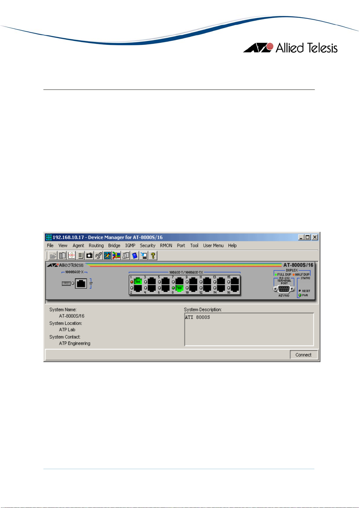
AT-8000S Series
This section describes Device Manager menus and operations specific to the AT-8000S
Series.
Topics:
• Main Window
• Agent Menu
• Routing Menu
• Bridge Menu
• IGMP Menu
• Security Menu
• RMON Menu
• Port Menu
Main Window
AT-8000S/16
AlliedView™-EMS 4.0.1 Device Management Guide Page 57 of 411
Page 58

AT-8000S/24, AT-8000S/48 and POE Models
The AT-8000S/24, AT-8000S/24POE, AT-8000S/48 and AT-8000S/48POE can be combined
to form a single stack of up to 6 units.
AlliedView™-EMS 4.0.1 Device Management Guide Page 58 of 411
Page 59

Device Manager LEDs for AT-8000S Series
LED State Description
PWR Green The switch is receiving power.
STACK ID Orange
The stacked unit is either the Stacking Master or the Backup
Master.
Gray
The switch is a set to standalone mode.
Green
The stacked unit is a slave switch.
DUPLEX Green
Orange
The port is operating in full-duplex mode.
The port is operating in half-duplex mode.
Note - When multiple units of the AT-8000S series are stacked together, port numbering is
continuous based on the Box ID.
• Box ID 1 - 1 to 54
• Box ID 2 - 55 to 108
• Box ID 3 - 109 to 162
• Box ID 4 - 163 to 216
• Box ID 5 - 217 to 270
• Box ID 6 - 271 to 324
This numbering scheme assumes that a unit can have a maximum of 54 ports.
Combo ports on the AT-8000S/24 and AT-8000S/24POE devices are assigned port
numbers 49 and 50.
Note - The current firmware version does not allow Device Manager to detect the presence
of an SFP module in any of the SFP slots unless there is an active connection on the SFP
ports. As a result, SFP images will appear on the device panel only if there is an established
connection on the physical SFP ports.
Agent Menu
From the Agent menu, you can view and edit the system information for the device, or log
into the CLI using Telnet.
System Info
Displays basic system information, including system name, location, contact and
description.
Note - The current firmware version accepts up to 160 characters for the System
Name parameter.
AlliedView™-EMS 4.0.1 Device Management Guide Page 59 of 411
Page 60

Device Info
General Info
Displays common management information.
Active Software File
Displays the currently available images on the flash.
Physical Description
Basic Info
Displays the number of stack units.
Module Info
Displays module information for each unit in the system.
Port Attributes
Displays port information.
Stack Info
Displays information about the stacked devices.
Stack Active Unit ID
Displays the current unit ID of the device after reset.
Note - AT-8000S/16: The current firmware version allows the Active Unit ID
After Reset parameter to be configured but the value is not saved after it is
rebooted.
Power Supply Info
Displays information about the power supply and redundant power supply.
Fan Info
Displays fan status.
Unit General Info
Displays the device's software versions.
Note - The current firmware version accepts up to 160 characters for the
Serial Number and Asset Tag parameters but truncates them to 31 and 16
characters respectively.
Note - The current firmware version is unable to display any value for the
Service Tag parameter.
Unit Environment Info
Displays the device's main power supply and temperature status.
AlliedView™-EMS 4.0.1 Device Management Guide Page 60 of 411
Page 61

Software Packages
Displays the device's software packages.
Management Info
General Management
Displays common management information.
Flash File System
Basic Info
Displays the flash file size of the device.
File List
Displays the device's list of files.
Note - The current firmware version does not allow the Row Status
parameter to be configured.
Jumbo Frames
Displays the current jumbo frames status.
Management ACL
Basic Info
Displays basic information about the management access list.
Note - The current firmware version does not allow the Active List Name parameter
to be configured.
Access Lists
Displays information about access lists.
Mid-level Management
Alarm Options
Displays information about alarm options.
Note - The current firmware version does not allow the Alarm Enabling parameter
to be configured.
MIB Tree
Displays information about the device's MIB tree.
Tuning
Agent Diagnostics
Displays diagnostic information about the agent.
Note - The current firmware version returns a 'noSuchName' value for the Location
parameter.
AlliedView™-EMS 4.0.1 Device Management Guide Page 61 of 411
Page 62

General Tuning
Displays general tuning information.
Note - The current firmware version accepts values in the range [0-255] inclusive for
the Debug Level parameter.
Max Entries Tuning
Displays information about the maximum entries in tuning.
Note - The current firmware version does not allow the following parameters to be
configured:
Max IP Next Hop Entries After Reset
Max IP Prefixes After Reset
Max IP ECMP Entry After Reset
Max IP Interfaces After Reset
TCP Tuning
Displays the memory pool size for tcp tuning.
Radius Tuning
Displays the memory pool size for radius tuning.
Syslog Tuning
Displays the current cache size and its size after reset.
Management ACL Tuning
Displays the current number of access rules and the number after reset.
SSH Tuning
Displays the current number of the maximum number of authorized keys and its
value after reset.
Terminal Sessions
Displays the current number of maximum sessions and its value after reset.
DNS Client Tuning
Displays the maximum values of the cache entries and the negative cache entries
before and after reset.
Tuning Parameters
Displays the current value, value after reset, default value, minimum and maximum
value of the different tuning parameters.
Host Parameters
Displays the corresponding value of the different host parameters.
AlliedView™-EMS 4.0.1 Device Management Guide Page 62 of 411
Page 63

Terminal Debug Mode
Displays the terminal debug mode password.
Note - The current firmware version does not allow the Terminal Debug Mode
Password to be configured.
Telnet
Basic Info
Displays the basic telnet information.
Telnet Sessions
Displays the login time, client ip address and telnet session status.
CLI Info
Displays information if the file is enabled or not.
LCLI Info
Displays information about the device's Telnet sessions and SSH sessions if enabled
or not.
Note - Valid MIB Set values for the History Size, Telnet History Size and SSH History
Size parameters are in the range [10-160] inclusive. Attempting to set these
parameters to a value outside of the valid range will result in the error message:
"The error occurred with 'Set' operation. Error: bad value."
RS-232
Displays the configuration of the baud rate of the device.
Web
Displays the configuration about the HTTP and HTTPS Port the device used.
Date and Time
Time Synchronization
Displays the configuration about the device's date/time and time zone.
Note - The current firmware version does not allow the Managed Time and Managed
Date parameters to be configured.
Note - Device Manager always treats objects of type OCTET STRING as a sequence
of bytes in hexadecimal format and does not convert them to plain text format
when necessary. As a result, the DST End and the DST Start parameters will neither
be readable nor configurable.
AlliedView™-EMS 4.0.1 Device Management Guide Page 63 of 411
Page 64

Note - Valid MIB Set values for the DST Offset parameter should range from 1 to
1440. However, the current firmware version allows the user to enter values in the
range [-2147483648 to 2147483647] inclusive. Attempting to enter values greater
than 2147483647 will cause the new value to be converted to its equivalent wraparound value; i.e., 2147483648 will become -2147483648, 2147483649 will become 2147483647, and so on.
SNTP/NTP Client Config
Displays information about SNTP/NTP client configuration.
Note - Valid MIB Set values for the Polling Interval parameter should range from 60
to 86400. However, the current firmware version allows the user to enter values in
the range [-2147483648 to 2147483647] inclusive. Attempting to enter values
greater than 2147483647 will cause the new value to be converted to its equivalent
wrap-around value; i.e., 2147483648 will become -2147483648, 2147483649 will
become -2147483647, and so on.
SNTP Config
Displays information about SNTP client configuration.
Note - The current firmware version returns a 'noSuchName' value for the
Broadcast Poll State and Anycast Poll State parameters.
Broadcast Mode
Displays information about broadcast mode per interface.
SNTP Server Info
Displays information about trusted SNTP servers to be queried in unicast or
broadcast mode.
Authentication Keys
Displays information about keys information for authentication of NTP packets.
System Log
Basic Info
Displays information and configuration of the device's log files.
Note - Setting the Clear Log File and Clear Cache parameters to a value other than 0
will delete the log file and clear the cache memory but the value used will not be
retained.
Event Log
Displays information about events sent to the system log file.
Error Log
Displays information about errors registered to the system cache.
AlliedView™-EMS 4.0.1 Device Management Guide Page 64 of 411
Page 65

Syslog Device
Displays information about Syslog diagnostic messages.
Note - Device Manager does not handle 8-bit string parameters correctly. As a
result, the Syslog Device Control parameter will display the string "00000000" and
will not be configurable.
Syslog Collector
Displays the information to generate syslog messages to an aggregating agent or
collector.
Syslog Application
Displays information about a managed entity that provides individual control over
the severity level of the messages that it will generate.
Note - The current firmware version does not allow the Severity parameter to be
configured.
Reset
Resets the switch.
Telnet
Starts a Telnet connection to the switch.
WEB Browser
Connects to the switch's HTTP server.
Routing Menu
From the Routing menu, you can view and edit information about the switch's routing
functions.
IP
ARP Table
Displays the ARP cache on the switch.
Address Table
Standard
Displays the list of IP interfaces on the switch.
Additional Info
Displays additional information about the address table.
Note - The current firmware version does not allow the IP Interface Owner
parameter to be configured.
AlliedView™-EMS 4.0.1 Device Management Guide Page 65 of 411
Page 66

Note - The Backup Address parameter is not applicable to the AT-8000S
module and should be ignored.
Static Route Table
Displays the IP static routing table.
Note - The current firmware version does not allow the Routing Type parameter to
be set to ‘local’ for all models except the AT-8000S/16. For the AT-8000S/16, the
Routing Type parameter cannot be set to ‘remote.’
IP Statistics
Displays statistics about IP routing, including the number of IP datagrams received.
Note - The current firmware version does not allow the Forwarding Status
parameter to be configured.
ARP Table Config
Displays configuration information about ARP.
I/F Name-Address Translation
Displays information about the IP interface's name translated to an IP interface
address.
TFTP
Displays configuration information about the TFTP.
UDP
TCP
Note - The current firmware version does not allow the Get Config File parameter
to be configured to receive image/config/boot files from a TFTP server.
Note - The current firmware version does not allow the Send Config File parameter
to be configured to send config/image/boot files to a TFTP server.
Listener Info
Displays UDP listener information.
UDP Statistics
Displays UDP statistics.
Connection Info
Displays TCP connection-specific information.
Note - The current firmware version does not allow the Connection Status
parameter to be configured.
TCP Statistics
Displays TCP statistics.
AlliedView™-EMS 4.0.1 Device Management Guide Page 66 of 411
Page 67

CIDR
Route Number
Displays the number of valid CIDR entries.
Route Table
Displays the CIDR routing tables.
Note - The current firmware version does not allow the following parameters to be
configured:
Destination Port Number
Routing Protocol MIB
Destination Metric 2
Destination Metric 3
Destination Metric 4
Destination Metric 5
Note - The current firmware version does not allow the Routing Type parameter to
be set to ‘local’ for all models except the AT-8000S/16. For the AT-8000S/16, the
Routing Type parameter cannot be set to ‘remote.
ICMP
ICMP Statistics
Displays ICMP Statistics.
Error Messages
Displays the variable that controls the ability to generate ICMP error messages.
DNS Resolver
Resolver Config
Displays information about the DNS client.
Note - The current firmware version does not allow the Reset parameter to be set
to "reset".
Basic Counters
Displays information about basic DNS couters.
Counters by OpCode
Displays information about the current count of resolver queries and answers.
Counters by Response Code
Displays information about the current count of responses to resolver queries.
Lame Delegation Overflows
Displays information about number of times the resolver attempted to add an entry
to the lame delegation table.
AlliedView™-EMS 4.0.1 Device Management Guide Page 67 of 411
Page 68

Cache Info
Displays information about a collection of objects providing access to and control of
a DNS resolver's cache.
Negative Cache Info
Displays information about a collection of objects providing access to and control of
a DNS resolver's negative response cache.
Additional Counters
Displays information about a collection of objects providing further instrumentation
applicable to many but not all DNS resolvers.
Bridge Menu
From the Bridge menu, you can view and edit bridge information such as the forwarding
database and the spanning tree status.
Forwarding Database
Standard View
Displays the Forwarding Database table as returned by the device.
Enhanced View
Displays the Forwarding Database table on a per port basis. User can select a port
or group of ports to view its corresponding Forwarding Database entries.
Aging Time Info
Displays information about the device's aging time.
Spanning Tree Info
STP
Standard
Displays the spanning tree information such as the STP version and path cost.
Additional Info
Displays additional STP information like supported type.
MSTP
Basic Info
Displays the basic information about MSTP.
Instance Info
Displays information that contains Mstp instance specific information for the
Multiple Spanning Tree Protocol.
VLAN Info
Displays information about the allocation of vlans to groups.
AlliedView™-EMS 4.0.1 Device Management Guide Page 68 of 411
Page 69

Statistics
Displays statistics about frames received/transmitted on the switch port.
Basic Bridge Info
Displays basic bridge information.
Bridge Port Info
Displays statistics about frames received/transmitted on the switch port.
Note - The current firmware version does not allow the Number of Traffic Class parameter
to be configured.
802.1p
Device Capabilities
Displays information on the device capabilities.
Port Priority Group
Displays information about the port priority.
Traffic Class
Displays information about the traffic class and traffic class priority.
Note - Valid MIB Set values for the Traffic Class parameter are in the range [0-3]
inclusive. Attempting to set this parameter to a value outside of the valid range will
result in the error message: “The error occurred with ‘Set’ operation. Error: bad
value.”
MAC Table Info
Displays MAC table information.
IGMP Menu
From the IGMP menu, you can view and edit IGMP information such as IGMP queries and
reports sent between devices, VLAN's IGMP functions and interfaces on which IGMP is
enabled.
MAC Multicast Info
Displays configurations of the enabling/disabling multicast.
IGMP Config
Displays configurations of the Internet Group Management Protocol function.
VLAN Info
Displays configurations of the VLAN information.
AlliedView™-EMS 4.0.1 Device Management Guide Page 69 of 411
Page 70

Security Menu
From the Security menu, you can view and edit different security and authentication
protocols SSL, SSH, and port-based authentication.
Authentication/Authorization/Accounting
Basic Info
Displays basic information about Authentication/Authorization/Accounting.
Note - The current firmware version does not allow the EAP Current Method List
parameter to be configured.
Method Lists
Displays information about all method lists.
Note - The current firmware version does not allow the Row Status parameter to be
configured.
Lines
Displays information about all lines, their passwords and their authorization levels.
Note - The current firmware version does not allow the Password, Row Status and
Password Valid Time parameters to be configured.
Note - The current firmware version is unable to display any value for the Password
Expiry Date parameter.
Local Users
Displays information about all usernames, their passwords and their authorizations.
Note - The current firmware version does not allow the User Password, Row Status
and Password Valid Time parameters to be configured.
Note - The current firmware version is unable to display any value for the Password
Expiry Date parameter.
Authenticated Users
Displays all the current users that have been authenticated.
EAP Method Lists
Displays information about all EAP method lists.
Note - The current firmware version does not allow the Row Status parameter to be
configured.
AlliedView™-EMS 4.0.1 Device Management Guide Page 70 of 411
Page 71

Port-based Authentication
PAE Port Info
Displays the system level information for each port supported by the Port Access
Entity.
Note - The current firmware version returns a 'noSuchName' value for the Port
Number parameter.
Authenticator PAE Info
Displays configuration objects for the Authenticator PAE associated with each port.
Note - The current firmware version returns a 'noSuchName' value for the Port
Number parameter.
Note - The current firmware version does not allow the Administrative Controlled
Directions and Key Transmission Status parameters to be configured.
Authenticator PAE Statistics
Displays statistics objects for the Authenticator PAE associated with each port.
Note - The current firmware version returns a 'noSuchName' value for the Port
Number parameter.
Authenticator PAE Diagnostics
Displays diagnostics objects for the Authenticator PAE associated with each port.
Note - The current firmware version returns a 'noSuchName' value for the Port
Number parameter.
Authenticator PAE Session Statistics
Displays session statistics objects for the Authenticator PAE associated with each
port.
Note - The current firmware version returns a 'noSuchName' value for the following
parameters:
Port Number
Received Octets
Transmitted Octets
Received Frames
Transmitted Frames
Note - The current firmware version is unable to display any value for the User
Name parameter.
AlliedView™-EMS 4.0.1 Device Management Guide Page 71 of 411
Page 72

RADIUS
Basic Info
Displays basic RADIUS information.
RADIUS Server Info
Displays the IP address, UDP port number for authentication and accounting
request, and current status of the RADIUS server.
Note - The current firmware version does not allow the Usage parameter to be set
to 'wireless authentication'.
Authentication Client Info
Displays the number of RADIUS Access-Response packets received from unknown
addresses and the identifier of the RADIUS authentication client.
Note - The current firmware version is unable to display any value for the Client ID
parameter.
Authentication Server Info
Displays the list of RADIUS authentication servers with which the client shares a
secret.
Accounting Client Info
Displays the number of RADIUS Access-Response packets received from unknown
addresses and the identifier of the RADIUS accounting client.
Note - The current firmware version is unable to display any value for the Client ID
parameter.
Accounting Server Info
Displays the list of RADIUS accounting servers with which the client shares a secret.
TACACS+
Basic Info
Displays basic TACACS+ information.
TACACS+ Server Info
Displays information about TACACS+ server.
Secure Shell
SSH Server
Displays information about the status of public key authentication and the type of
regenerated host key.
Note - Configuring the Regenerate Host Key parameter will result in the error
message: "The error occurred with 'Set' operation. Error: time out occurred" but a
key will still be successfully generated.
AlliedView™-EMS 4.0.1 Device Management Guide Page 72 of 411
Page 73

SSH Client
Displays information about the user name ssh client will use and the value of the
regenerated self key.
Note - The current firmware version accepts up to 60 characters for the User Name
parameter.
Note - Setting the Regenerate Self Key parameter to "rsa" or "dsa" will result in the
error message: "The error occurred with 'Set' operation. Error: time out occurred".
Connection with the AT-8000S device will be lost and the only way to re-establish
connection will be to perform a manual reset.
Note - The current firmware version does not allow the Regenerate Self Key
parameter to be set to 'rsa1'.
Secure Socket Layer
Basic Info
Displays basic SSL information.
Note - The current firmware version does not allow the Certificate Save parameter
to be configured.
Certificate Generation
Displays information about the generated keys and self signed certificates.
Note - The current firmware version does not allow any of the parameteres under
this table to be configured.
Export Certificate
Displays information about the saved data from RAM and flash.
Import Certificate
Displays information about the copied external certificate of the device.
RMON Menu
From the RMON menu you can view and edit the RMON MIB.
Statistics
Displays traffic statistics in the network segment attached to each port.
History Control Table
Displays the RMON History table.
Alarm Table
Displays the RMON Alarm table.
AlliedView™-EMS 4.0.1 Device Management Guide Page 73 of 411
Page 74

Event Table
Displays the RMON Event table.
Event Log
Displays the RMON Event log.
Port Menu
From the Port menu, you can view and edit MIB information about the port.
Utilization
Displays the port's utilization information.
Note - The current firmware version does not allow Device Manager to display Utilization
information.
Interface Info
Standard
Displays port statistics such as the number of frames received and transmitted on
the port, bytes received and transmitted on the port, and port status.
Note - The current firmware version does not allow the Promiscuous Mode
parameter to be configured.
Note - The current firmware version returns a "noSuchName" value for the
following parameters:
Received Error Packets
Transmitted Error Packets
Transmitted Buffer Length
Received Bytes (HC)
Received Unicast Packets (HC)
Received Multicast Packets (HC)
Received Broadcast Packets (HC)
Transmitted Bytes (HC)
Transmitted Unicast Packets (HC)
Transmitted Multicast Packets (HC)
Transmitted Broadcast Packets (HC)
Additional Info
Displays additional information about the port's interface info.
Error Statistics
Standard
Displays error statistics for the port.
Note - The Ethernet Chip Set parameter is not applicable to the AT-8000S series
and should be ignored.
AlliedView™-EMS 4.0.1 Device Management Guide Page 74 of 411
Page 75

Note - The current firmware version returns a "noSuchName" value for the
following parameters:
Alignment Error Frames
Multi Collision Frames
SQE Test Errors
Deferred Transmissions
Excessive Collisions
Internal MAC Transmit Errors
Carrier Sense Errors
Symbol Errors
Additional Info
Displays information about a table containing 64-bit versions of error counters.
Note - The current firmware version is unable to display any value for the Port
Number and Alignment Error Frames (HC) parameters.
Note - The current firmware version returns a ‘noSuchName’ value for the Internal
MAC Transmit Errors (HC) and Internal MAC Received Errors (HC) parameters.
Detail Info
Displays detailed port information such as duplex mode.
Note - The current firmware version does not allow the following parameters to be
configured:
Note - Device Manager does not handle 8-bit string parameters correctly. As a
result, the Autonegotiation Capabilities Config parameter will display an
unrecognizable value and will not be configurable. The Autonegotiation Capabilities
Status and Remote Autonegotiation Capabilities parameters will also display
unrecognizable values.
Tagged Mode
Default Priority
Row Status
Port Flow Control Config
Port Speed
Reactivate
Combo Ethernet Config
Note - The Physical Address Type parameter is not applicable to the AT-8000S
series and should be ignored.
Note - The combo ports will not display the Port Context Menu on right-mouse
click if logged-on in SNMPv3 mode using a user account with no read-write access
to the Transceiver Type parameter.
AlliedView™-EMS 4.0.1 Device Management Guide Page 75 of 411
Page 76

Spanning Tree Info
STP
Standard
Displays the port's spanning tree parameters.
Additional Info
Displays a list of information maintained by every port about the Spanning
Tree Protocol state for that port.
MSTP
MSTI
Displays a list of information maintained by every pair <msti, port> about the
Spanning Tree Protocol state for that pair.
CIST
Displays a list of information maintained by every port of the CIST.
Enable
Enables the port.
Disable
Disables the port.
Port Lock
Basic Info
Displays basic information about port lock.
Interfaces Range
Displays information about port lock interfaces range.
MAC Control
MAC Control Sublayer
Displays information about the MAC Control sublayer on a single ethernet-like
interface.
Note - The current firmware version returns a 'noSuchName' value for the Unknown
Opcodes Received and Unknown Opcodes Received (HC) parameters.
MAC Control PAUSE
Displays information about the MAC Control PAUSE function on a single ethernetlike interface.
Note - Valid MIB Set values for the PAUSE Config parameter are "disabled" and
"enabledXmitAndRcv". Attempting to set this parameter to any other value will
result in the error message: "The error occurred with 'Set' operation. Error: bad
value."
AlliedView™-EMS 4.0.1 Device Management Guide Page 76 of 411
Page 77

Note - The current firmware version returns a "noSuchName" value for the
Received Frames (HC) and Transmit Frames (HC) parameters.
Port Trunking
Basic Info
Displays basic information about port trunking.
Note - The current firmware version does not allow any of the parameters under
this table to be configured.
Balancing Criteria
Displays information about Aggregate Index.
Note - The current firmware version does not allow the Balance Layer, Used
Addresses and Broadcast Type parameters to be configured.
Aggregator Info
Displays information about every Aggregator that is associated with this system.
Note - Valid MIB Set values for the Actor Administrative Key parameter are in the
range [1 - 65535] inclusive. Attempting to set this parameter to a value outside of
the valid range will result in the error message: “The error occurred with ‘Set’
operation. Error: bad value.”
Aggregator Port List
Displays Link Aggregation Control information for every Aggregation Port
associated with this device.
Aggregation Port Info
Displays a list of Link Aggregation Control configuration parameters for each
Aggregation Port on this device.
Note - The current firmware version returns a 'noSuchName' value for the Port
Number parameter.
Note - Device Manager does not handle 8-bit string parameters correctly. As a
result, the Actor Administrative Status and Partner Administrative Status parameters
will display unrecognizable values and will not be configurable. The Actor
Operational Status and Partner Operational Status parameters will also display
unrecognizable values.
Note - The current firmware version does not allow the Actor Administrative Key
and Partner Administrative System ID parameters to be configured.
Storm Control
Basic Info
Displays basic information about storm control.
AlliedView™-EMS 4.0.1 Device Management Guide Page 77 of 411
Page 78

Storm Control Protection
Displays information about the storm control protection per port.
Note - Only the Broadcast Enable and Multicast Enable parameters can be
configured.
Storm Control Group
Displays information about group id for each supported frame type defined per port.
AT-8000S Series
AlliedView™-EMS 4.0.1 Device Management Guide Page 78 of 411
Page 79

AT-8300GB Series
This section describes Device Manager menus and operations specific to the AT-8300GB
Series.
Topics:
• Main Window
• Agent Menu
• Bridge Menu
• RMON Menu
• Port Menu
• Stacking Menu
AlliedView™-EMS 4.0.1 Device Management Guide Page 79 of 411
Page 80

Main Window
AT-8326GB
AlliedView™-EMS 4.0.1 Device Management Guide Page 80 of 411
Page 81

The AT-8326GB supports up to 6 AT-8326GB stacked switches or any of the following
mixed stack combinations of AT-8326GB and AT-8350GB switches:
• Two AT-8326GB switches and one AT-8350GB switch
• Two AT-8326GB switches and two AT-8350GB switches
• Three AT-8326GB switches and one AT-8350GB switch
• Four AT-8326GB switches and one AT-8350GB switch
Note - When 3 or more AT-8326GB devices are stacked together, expect the twisted pair
port image of Port 26 on the last device on the stack to turn green. This is because the
current firmware version returns 'on-line' for the Port Link State parameter of the port
even if there is no link established.
AT-8350GB
The AT-8350GB supports up to 3 stacked AT-8350GB switches.
Note - The current firmware version does not allow Device Manager to support the RPS
LED.
Note - The current firmware version does not allow Device Manager to support expansion
modules that may be installed on the AT-8350GB.
Device Manager LEDs for AT-8300GB Series
LED State Description
PWR Green The switch is receiving power.
STACK ID Green The switch's position in the switch stack.
AlliedView™-EMS 4.0.1 Device Management Guide Page 81 of 411
Page 82

Device Manager LEDs for AT-8300GB Series
LED State Description
DUPLEX Green
Orange
The port is operating in full-duplex mode.
The port is operating in half-duplex mode.
Note - Status information for the gigabit ports will always be reflected on the RJ-45 gigabit
port images regardless of whether the gigabit ports have been set to operate as GBIC ports
or as Twisted Pair ports.
Note - When Global STP is enabled, the current firmware version sets the Port State
parameter of inactive ports to 'blocking'. As a result, expect port images for inactive ports
to turn yellow in Device Manager .
Note - The current firmware version does not allow Device Manager to detect the presence
or absence of a GBIC module in any of the GBIC slots. As a result, the GBIC slots on the
device image will remain empty regardless of whether or not GBIC modules are physically
present in the slots.
Agent Menu
From the Agent menu, you can view and edit the system information for the device, or log
into the CLI using Telnet.
System Info
Displays basic system information, including system name, location, contact and
description.
Note - The current firmware version does not allow multiple-word values for the
System Name parameter.
Note - Device Manager allows the user to enter up to 255 characters for the System
Contact, System Name and System Location parameters but the current firmware
version truncates them to 64 characters.
Firmware Info
Displays the version of the software running on the managed device.
Network Info
Displays network-related information such as the device IP address and the default
gateway address.
Note - The current firmware version does not save changes made to the DNS
Server and the Default Domain Name parameters.
AlliedView™-EMS 4.0.1 Device Management Guide Page 82 of 411
Page 83

DHCP Info
Displays DHCP information including the DHCP System Group and DHCP Timer
Group.
Manager Address Info
Displays the IP address of the management station.
Reset
Resets the switch.
Telnet
Starts a Telnet connection to the switch.
WEB Browser
Connects to the switch's HTTP server.
Bridge Menu
From the Bridge menu, you can view and edit bridge information such as the forwarding
database and the spanning tree status.
Forwarding Database
Standard View
Displays the Forwarding Database table as returned by the device.
Enhanced View
Displays the Forwarding Database table on a per port basis. User can select a port
or group of ports to view its corresponding Forwarding Database entries.
Discard/Aging Time Info
Displays information about the number of address entries that were learned but
discarded because of lack of memory or the entry's aging timer has expired.
Note - The current firmware version accepts values in the range [10-1000000]
inclusive for the Aging Time parameter.
Spanning Tree Info
Displays spanning tree parameters such as priority and cost.
Statistics
Displays statistics about frames received/transmitted on the switch's ports.
RMON Menu
From the RMON menu you can view and edit the RMON MIB.
AlliedView™-EMS 4.0.1 Device Management Guide Page 83 of 411
Page 84

Statistics
Displays traffic statistics in the network segment attached to each port.
History Control Table
Displays the RMON History table.
Alarm Table
Displays the RMON Alarm table.
Event Table
Displays the RMON Event table.
Event Log
Displays the RMON Event log.
Port Menu
From the Port menu, you can view and edit MIB information about the port.
Utilization
Displays the port's utilization information.
Interface Info
Displays port statistics such as the number of frames received and transmitted on
the port, bytes received and transmitted on the port, and port status.
Note - Valid MIB Set values for the Administration Status parameter are 'up' and
'down'. Attempting to set this parameter to any other value will result in the error
message: "The error occurred with 'Set' operation. Error: gen Error."
Detail Info
Displays detailed port information such as duplex mode.
Note - The Port Transmit Pacing Configuration parameter is not applicable to the
AT-8300GB Series.
Note - The Port VLAN Tag Priority parameter has a fixed value of 'use vlan priority'
and cannot be modified.
Note - The current firmware version does not allow the Port Bridge ID parameter
to be configured. Attempting to configure this parameter will result in the error
message: "The error occurred with 'Set' operation. Error: bad value".
Note - When a port's Port Speed and Mode parameter is set to 'auto sense', the
current firmware version does not update its Port Duplex Status parameter with the
negotiated mode. As a result, the port's Port Duplex Status parameter will always
display 'auto sense' and its corresponding Duplex LED will always be green
regardless of the actual connection mode.
AlliedView™-EMS 4.0.1 Device Management Guide Page 84 of 411
Page 85

Note - The Port Name parameter is not applicable to the AT-8300GB Series.
Note - Valid MIB Set values for the Port State parameter are 'enabled' and 'disabled'.
Attempting to set this parameter to any other value will result in the error message:
"The error occurred with 'Set' operation. Error: bad value."
Spanning Tree Info
Displays the port's spanning tree parameters.
Enable
Enables the port.
Disable
Disables the port.
QoS
Displays QoS parameters and allows enabling of QoS status and setting priority
queue.
Port Mirroring
Displays port mirroring parameters and allows configuration of port mirroring state,
source and destination.
IGMP Snooping
Displays the current state of IGMP Snooping and allows reconfiguration.
Stacking Menu
From the Stacking menu, you can view basic switch information as well as stacking
information.
Stacking Info
Displays information such as Product Type, Port Count, and Uplink Types for all
switches in the stack.
Note - The Uplink Port A MDA Type and Uplink Port B MDA Type parameters
return incorrect values.
Note - The Security Action parameter returns '???(0)' when the Security
Configuration parameter is set to 'disabled'.
AT-8300GB Series
AlliedView™-EMS 4.0.1 Device Management Guide Page 85 of 411
Page 86

AT-8400
This section describes Device Manager menus and operations specific to the AT-8400
switch.
Topics:
• Main Window
• Agent Menu
• Bridge Menu
• RMON Menu
• Port Menu
• Stacking Menu
AlliedView™-EMS 4.0.1 Device Management Guide Page 86 of 411
Page 87

Main Window
AT-8400
Device Manager LEDs for AT-8401 Management Module
LED State Description
FAN A Green
Gray
FAN B Green
Gray
MASTER Green
Gray
FAN TRAY A is installed and is operating correctly.
FAN TRAY A is not installed.
FAN TRAY B is installed and is operating correctly.
FAN TRAY B is not installed.
The switch is the master of an enhanced stack.
The switch is either a slave switch of an enhanced stack or
the switch is not a member of an enhanced stack.
AlliedView™-EMS 4.0.1 Device Management Guide Page 87 of 411
Page 88

Device Manager LEDs for AT-8401 Management Module
LED State Description
RPS Green
The switch is receiving power from the redundant power
supply (PWR B).
Gray
The switch is receiving power from the main power supply
(PWR A).
PWR Green
The switch is receiving power from the main power supply
(PWR A).
Gray (Only if
The main power supply is not functioning.
RPS is installed)
Note - Please refer to AT-8400 Line Cards for the operations and behavior of the line cards
installed on the chassis.
Note - The FAN A and FAN B LEDs are always green regardless of whether or not fan trays
are actually installed.
Note - The PWR LED is always green and the RPS LED is always gray regardless of whether
the switch is receiving power from the main power supply or the redundant power supply.
Note - Some parameters, when configured, may at times cause a temporary loss of
connection. When this happens, the following error message appears: "The error occurred
with 'Set' operation. Error: time out occurred.". This will not affect the application in any
way.
Agent Menu
From the Agent menu, you can view and edit the system information for the device, or log
into the CLI using Telnet.
System Info
Displays basic system information, including system name, location, contact and
description.
Network Info
Displays network-related information such as the addresses of the default gateway
and the agents.
Note - The current firmware version does not allow the DNS Server and Default
Domain Name parameters to be configured. Attempting to configure these
parameters will result in the error message: "The error occurred with 'Set'
operation. Error: gen Error.".
AlliedView™-EMS 4.0.1 Device Management Guide Page 88 of 411
Page 89

Chassis Info
Displays chassis information including the firmware information.
Note -The current firmware version does not allow the Power A Status and Power B
Status parameters to be configured. Attempting to configure these parameters will
result in the error message: "The error occurred with 'Set' operation. Error: gen
Error.".
Line Card Info
Displays information for each line card including line card type and line card
temperature.
MAC Address Table
Displays a list of static MAC address configured on the switch.
Note - Valid MIB Set values for the MAC Address Entry Status parameter are 'active',
'not in service' and 'destroy'. Attempting to set this parameter to any other value
will result in error message: "The error occurred with 'Set' operation. Error: bad
value".
Reset
Resets the switch.
Telnet
Starts a Telnet connection to the switch.
WEB Browser
Connects to the switch's HTTP server.
Bridge Menu
From the Bridge menu, you can view and edit bridge information such as the forwarding
database and the spanning tree status.
Forwarding Database
Displays the Forwarding Database table.
Note - It may take some time to retrieve Forwarding Database information. As a
result, some Forwarding Database parameters may not show any value. To avoid
this, click on File > Property > Polling options and set the Polling Interval parameter
to 25 seconds or longer.
Discard/Aging Time Info
Displays information about the number of address entries that were learned but
discarded because either there was a lack of memory or the entry's aging timer
expired.
AlliedView™-EMS 4.0.1 Device Management Guide Page 89 of 411
Page 90

Spanning Tree Info
Displays spanning tree parameters such as spanning tree status and spanning tree
version.
Note - When setting the Spanning Tree Status parameter to 'enabled', connection to
the AT-8400 is temporarily lost. As a result, the following error message appears:
"The error occurred with 'Set' operation. Error: time out occurred.".
Note - Setting the value of the Spanning Tree Version parameter to 'stp' will result in
a permanent loss of connection. To re-establish connection, restart the device.
Statistics
Displays statistics about frames received/transmitted on the switch's ports.
Note - Ports are numbered continuously from top to bottom, across all installed line
cards, starting from the leftmost line card all the way through the rightmost line
card.
RMON Menu
From the RMON menu you can view and edit the RMON MIB.
Statistics
Displays traffic statistics in the network segment.
History Control Table
Displays the RMON History table.
Note - The current firmware version does not support the "historyControlTable"
MIB object of RFC1757. As a result, Device Manager displays the error message
"Failed to get MIB data." when the History Control Table option is selected from the
RMON menu.
Alarm Table
Displays the RMON Alarm table.
Event Table
Displays the RMON Event table.
Event Log
Displays the RMON Event log.
Port Menu
From the Port menu, you can view and edit MIB information about the port.
AlliedView™-EMS 4.0.1 Device Management Guide Page 90 of 411
Page 91

Note - Ports are numbered continuously from top to bottom, across all installed line cards,
starting from the leftmost line card all the way through the rightmost line card. This applies
to the following submenu options:
Utilization
Interface Info -> Standard
Error Statistics -> Standard
Spanning Tree Info
Utilization
Displays the port's utilization information.
Interface Info
Displays port statistics such as the number of frames received and transmitted on
the port, bytes received and transmitted on the port, and port status.
Note - Valid MIB Set values for the Administration Status parameter are 'up' and
'down'. Attempting to set this parameter to any other value will result in the error
message: "The error occurred with 'Set' operation. Error: bad value.".
Error Statistics
Displays error statistics such as alignment error frames and carrier sense errors.
Detail Info
Displays detailed port information such as duplex mode.
Note - The current firmware version does not allow the Port Name parameter to be
set to NULL. Attempting to set this parameter to NULL will result in the error
message: "The error occurred with 'Set' operation. Error: bad value.".
Spanning Tree Info
Displays the port's spanning tree parameters.
Note - The current firmware version does not allow the Port parameter to be
configured. Attempting to configure this parameter will result in the error message:
"The error occurred with 'Set' operation. Error: readOnly".
Port Security
Displays the port security attributes for each physical port present in the switch.
Enable
Enables the port.
Disable
Disables the port.
Port Mirroring
AlliedView™-EMS 4.0.1 Device Management Guide Page 91 of 411
Page 92

Displays port mirroring parameters and allows configuration of port mirroring state
and port's source list.
Note - Valid MIB Set values for the Port Mirroring Configuration Entry Status
parameter are 'active', 'not in service' and 'destroy'. Attempting to set this
parameter to any other value will result in the error message: "The error occurred
with 'Set' operation. Error: bad value.".
Stacking Menu
From the Stacking menu, you can view basic switch information as well as stacking
information.
Stacking Info
Displays information such as Stack Switch ID, Stack Switch MAC Address, Stack
Switch Name, Stack Switch Mode, Stack Switch Software Version and Stack Switch
Model for all switches in the stack.
AT-8400
AlliedView™-EMS 4.0.1 Device Management Guide Page 92 of 411
Page 93

AT-8400 Line Cards
This section describes the AT-8400 Line Cards supported by Device Manager. If line cards
are installed on the AT-8400 chassis at the time Device Manager is called, they will be
displayed in their corresponding slots on the chassis image.
• AT-8411
• AT-8412
• AT-8413
• AT-8414
AT-8411
AT-8411
LED State Description
DUPLEX Green
Orange
The port is operating in full-duplex.
The port is operating in half-duplex.
Note - When a port on the AT-8411 line card is configured to auto-negotiate and is
connected to a 10/100 Mbps full-duplex port on another device, the current firmware
version returns the value 'half-duplex' for the Port Duplex Status parameter. As a result, the
Duplex LED turns orange instead of green.
AlliedView™-EMS 4.0.1 Device Management Guide Page 93 of 411
Page 94

AT-8412
AT-8412/MT AT-8412/SC
LED State Description
DUPLEX Green The port is operating in full-duplex.
Note - The current firmware version does not allow the Port Flow Control parameter of
ports on the AT-8412/MT and AT-8412/SC line cards to be set to 'auto'. Attempting to set
this parameter to 'auto' will result in the error message: "The error occurred with 'Set'
operation. Error: gen Error".
AlliedView™-EMS 4.0.1 Device Management Guide Page 94 of 411
Page 95

AT-8413
AT-8413GB/T
LED State Description
DUPLEX Green
Orange
The port is operating in full-duplex.
The port is operating in half-duplex.
Note - A GBIC image is always visible on the GBIC slot of the AT-8413GB/T line card image
even if there is no GBIC physically present in the slot.
Note - Status information for the AT-8413GB/T ports will always be reflected on the RJ-45
port image regardless of whether the port that is in actual use is the GBIC port or the
twisted pair port.
Note - When the 10/100/1000Base-T port of the AT-8413GB/T line card is configured to
auto-negotiate and is connected to a 10/100Mbps full-duplex port on another device, the
current firmware version returns the value 'half-duplex' for the Port Duplex Status
parameter. As a result, the Duplex LED turns orange instead of green.
AlliedView™-EMS 4.0.1 Device Management Guide Page 95 of 411
Page 96

AT-8414
AT-8414/SC AT-8414/ST
LED State Description
DUPLEX Green
Orange
The port is operating in full-duplex.
The port is operating in half-duplex.
Note - The Port Negotiation parameter of ports on the AT-8414/SC and AT-8414/ST line
cards has a fixed value of '10Mbps full-duplex' and cannot be modified.
AT-8400 Line Cards
AlliedView™-EMS 4.0.1 Device Management Guide Page 96 of 411
Page 97

AT-9000/24
This section describes Device Manager menus and operations specific to the AT-9000/24
switch.
Topics:
• Main Window
• Agent Menu
• Bridge Menu
• RMON Menu
• Port Menu
Main Window
AT-9000/24
Device Manager LEDs for AT-9000/24
LED State Description
PWR Green The switch is receiving power.
DUPLEX Green
Orange
The port is operating at full-duplex mode.
The port is operating at half-duplex mode.
Note - Disabled ports will not turn red.
AlliedView™-EMS 4.0.1 Device Management Guide Page 97 of 411
Page 98

Note - The current firmware version does not allow Device Manager to detect the presence
or absence of an SFP module in any of the SFP slots. As a result, the SFP slots on the device
image will always show SFP images regardless of whether or not SFP modules are physically
present in the slots.
Note - Status information for ports 21 to 24 will always be reflected on both the RJ-45 port
images and the SFP port images regardless of whether it is the RJ-45 or the SFP ports that
are actually in operation. However, if Device Manager detects that the established link
speed is less than 1Gbps, only the RJ-45 port images will turn green.
Note - When Global RSTP is enabled, the current firmware version sets the Port State
parameter of inactive ports to 'blocking'. As a result, expect port images for inactive ports
to turn yellow in Device Manager.
Agent Menu
From the Agent menu, you can view and edit the system information for the device, or log
into the CLI using Telnet.
System Info
Displays basic system information, including system name, location, contact and
description.
Note - The current firmware version accepts up to 64 characters for the System
Contact, System Name and System Location parameters.
Firmware Info
Displays firmware version.
Network Info
Displays network-related information such as the addresses of the default gateway
and the agents.
Manager Address Info
Displays the IP address of the management station.
Note - The current firmware version does not return the correct values for the Trap
Destination IP Address parameters if these are retrieved in bulk. As a result, all Trap
Destination IP Address parameters will display a value of '0.0.0.0' upon initial display
of the Manager Address Info table. To retrieve the correct values, a Get MIB Value
must be performed on each Trap Destination IP Address parameter, one at a time.
The same is true if their values need to be modified. A Set MIB Value would have to
be performed on each instance of the parameter, one at a time.
DHCP Info
Displays DHCP information including the DHCP System Group and DHCP Timer
Group.
AlliedView™-EMS 4.0.1 Device Management Guide Page 98 of 411
Page 99

Reset
Resets the switch.
Telnet
Starts a Telnet connection to the switch.
WEB Browser
Connects to the switch's HTTP server.
Bridge Menu
From the Bridge menu, you can view and edit bridge information such as the spanning tree
status.
Bridge Info
General
Displays basic bridge information such as the LAN ID, bridge address, number of
ports and the bridge type.
Port
Displays basic bridge information on a per port basis such as the LAN ID, port
number, circuit, delay exceeded discards and MTU exceeded discards.
Note - The current firmware version returns a NULL value for the Circuit
parameter.
Spanning Tree Info
Displays spanning tree parameters such as priority and cost.
Note - Values entered for the Root Maximum Aging Time, Root Hello Time and
Root Forward Delay Time parameters must be multiples of 100. Values that are not
multiples of 100 will be automatically rounded down to the nearest hundreds.
Statistics
Displays statistics about frames received/transmitted on the switch's ports.
RMON Menu
From the RMON menu you can view and edit the RMON MIB.
Statistics
Standard
Displays traffic statistics in the network segment attached to each port.
Note - The current firmware version does not support RFC1757. As a result, Device
Manager will display the error message "Failed to get MIB data."
AlliedView™-EMS 4.0.1 Device Management Guide Page 99 of 411
Page 100

Additional Info
Displays additional traffic statistics in the network segment such as frames
received/sent, collisions, broadcast frames and multicast frames.
Error
Displays error statistics in the network segment such as CRC errors, alignment
errors, bad frames received late collisions and total transmit errors.
Note - There may be times when Device Manager will not be able to successfully
retrieve error statistical information. When this happens, all parameters in this table
will display the value "retry over occurred". To prevent this from happening, do the
following:
Go to File -> Property.
Click on the Settings button in the Polling Options area.
Increase the value of the Timeout parameter in the Retry area.
History Control Table
Displays the RMON History table.
Note - The current firmware version does not support RFC1757. As a result, Device
Manager will display the error message "Failed to get MIB data."
Alarm Table
Displays the RMON Alarm table.
Event Table
Displays the RMON Event table.
Event Log
Displays the RMON Event log.
Port Menu
From the Port menu, you can view and edit MIB information about the port.
Utilization
Displays the port's utilization information.
Interface Info
Standard
Displays port statistics such as the number of packets received and transmitted on
the port, bytes received and transmitted on the port and port status.
Note - The current firmware version does not support the Specific Media MIB
parameter.
AlliedView™-EMS 4.0.1 Device Management Guide Page 100 of 411
 Loading...