

Page 1

AlliedView™-EMS 3.10
(Full Installation)
QoS MANAGER USER’S GUIDE
AlliedView™-EMS 3.10 QoS Manager User’s Guide Page 1 of 128
Page 2

TABLE OF CONTENTS
1 OVERVIEW........................................................................................................................................ 5
2 STARTING QOS MANAGER ..........................................................................................................6
3 MAIN WINDOW .............................................................................................................................. 7
3.1 INITIAL WINDOW .............................................................................................................................8
3.2 QOS/COS INFORMATION WINDOW ................................................................................................9
4 BASIC OPERATIONS .................................................................................................................... 11
4.1 ADD.................................................................................................................................................12
4.2 MODIFY ...........................................................................................................................................14
4.3 DELETE............................................................................................................................................16
4.4 INLINE TABLE EDITING ...................................................................................................................17
4.5 APPLY..............................................................................................................................................18
5 MENUS............................................................................................................................................. 20
5.1 FILE .................................................................................................................................................21
5.1.1 Open...................................................................................................... 21
5.1.2 Close ..................................................................................................... 24
5.1.3 Exit ........................................................................................................ 25
5.2 TOOLS.............................................................................................................................................26
5.2.1 Quick Setup.......................................................................................... 26
5.2.2 Refresh .................................................................................................. 28
5.2.3 Reboot................................................................................................... 29
5.3 HELP ...............................................................................................................................................30
5.3.1 Index...................................................................................................... 30
5.3.2 About .................................................................................................... 30
6 DEVICE SUPPORT ......................................................................................................................... 31
6.1 AT-8000S SERIES ...........................................................................................................................32
6.1.1 General ................................................................................................. 32
6.1.2 Port ....................................................................................................... 32
6.1.3 Scheduling ............................................................................................ 33
6.1.4 CoS Priority ......................................................................................... 33
6.1.5 DSCP Priority ...................................................................................... 33
6.1.6 Bandwidth............................................................................................. 33
6.2 AT-8600 SERIES..............................................................................................................................35
6.2.1 Classifiers.............................................................................................. 35
6.2.2 Flow Groups ......................................................................................... 40
6.2.3 Traffic Classes ...................................................................................... 40
6.2.4 Policies .................................................................................................. 42
6.2.5 Ports...................................................................................................... 42
6.2.6 Scheduling ............................................................................................ 42
6.2.7 Quick Setup.......................................................................................... 43
6.2.8 Notes..................................................................................................... 43
6.3 AT-8800 SERIES..............................................................................................................................44
6.3.1 Classifier ............................................................................................... 44
6.3.2 Flow Groups ......................................................................................... 49
6.3.3 Traffic Classes ...................................................................................... 49
6.3.4 Policies .................................................................................................. 51
AlliedView™-EMS 3.10 QoS Manager User’s Guide Page 2 of 128
Page 3

6.3.5 Ports...................................................................................................... 51
6.3.6 Scheduling ............................................................................................ 51
6.3.7 Quick Setup.......................................................................................... 52
6.3.8 Notes..................................................................................................... 52
6.4 AT-9000/24 ....................................................................................................................................53
6.4.1 General ................................................................................................. 53
6.4.2 Traffic Class.......................................................................................... 53
6.4.3 Port Priority ......................................................................................... 53
6.5 AT-9400 SERIES..............................................................................................................................54
6.5.1 Classifiers.............................................................................................. 54
6.5.2 Flow Groups ......................................................................................... 56
6.5.3 Traffic Classeses................................................................................... 57
6.5.4 Policies .................................................................................................. 59
6.5.5 Ports...................................................................................................... 60
6.5.6 Scheduling ............................................................................................ 60
6.5.7 Quick Setup.......................................................................................... 61
6.5.8 Notes..................................................................................................... 61
6.6 AT-9900 SERIES..............................................................................................................................62
6.6.1 Classifiers.............................................................................................. 62
6.6.2 Flow Groups ......................................................................................... 71
6.6.3 Traffic Classes ...................................................................................... 73
6.6.4 Policies .................................................................................................. 76
6.6.5 Ports...................................................................................................... 79
6.6.6 Scheduling ............................................................................................ 80
6.6.7 Quick Setup.......................................................................................... 81
6.6.8 Notes..................................................................................................... 82
6.7 AT-X900-24X SERIES......................................................................................................................84
6.7.1 Classifiers.............................................................................................. 84
6.7.2 Flow Groups ......................................................................................... 93
6.7.3 Traffic Classes ...................................................................................... 95
6.7.4 Policies .................................................................................................. 98
6.7.5 Ports.................................................................................................... 101
6.7.6 Scheduling .......................................................................................... 102
6.7.7 Quick Setup........................................................................................ 103
6.7.8 Notes................................................................................................... 104
6.8 RAPIER 24I.....................................................................................................................................107
6.8.1 Classifiers............................................................................................ 107
6.8.2 Flow Groups ....................................................................................... 113
6.8.3 Traffic Classeses................................................................................. 114
6.8.4 Policies ................................................................................................ 116
6.8.5 Ports.................................................................................................... 116
6.8.6 Scheduling .......................................................................................... 116
6.8.7 Quick Setup........................................................................................ 117
6.8.8 Notes................................................................................................... 117
6.9 SWITCHBLADE SERIES ..................................................................................................................119
6.9.1 Classifiers............................................................................................ 119
6.9.2 Flow Groups ....................................................................................... 123
6.9.3 Traffic Classes .................................................................................... 123
AlliedView™-EMS 3.10 QoS Manager User’s Guide Page 3 of 128
Page 4

6.9.4 Policies ................................................................................................ 125
6.9.5 Ports.................................................................................................... 126
6.9.6 Scheduling .......................................................................................... 126
6.9.7 Quick Setup........................................................................................ 126
6.9.8 Notes................................................................................................... 127
AlliedView™-EMS 3.10 QoS Manager User’s Guide Page 4 of 128
Page 5

1 Overview
QoS Manager is a tool that enables you to configure Quality of Service or Class
of Service on a device.
Topics
• Starting QoS Manager
• Main Window
• Basic Operations
• Menus
• Device Support
1 Overview
AlliedView™-EMS 3.10 QoS Manager User’s Guide Page 5 of 128
Page 6

2 Starting QoS Manager
QoS Manager can be started from Device Manager or from the command line.
In a Windows environment, QoS Manager can be started from the AlliedViewEMS program folder or from the Run command of the Start menu.
You can start QoS Manager from Device Manager by clicking on Tool > QoS
Manager on the main menu or by clicking on the QoS Manager icon
toolbar. If Device Manager is connected to a device, target host information is
automatically passed on to QoS Manager so that the QoS configuration of the
device can be retrieved and displayed in QoS Manager's main window.
2 Starting QoS Manager
on the
AlliedView™-EMS 3.10 QoS Manager User’s Guide Page 6 of 128
Page 7

3 Main Window
When started, QoS Manager displays one of the following windows, depending
on how it is started.
Topics:
• Initial Window
• QoS/CoS Information Window
3 Main Window
AlliedView™-EMS 3.10 QoS Manager User’s Guide Page 7 of 128
Page 8
3.1 Initial Window
If the target host is not specified, or if one or more connection parameters do
not match what is configured on the host, the following window appears.
Initial Window
To specify a target host from this window, select File → Open . If the target
host is a device model that is supported by QoS Manager, the QoS/CoS
Information Window displaying the target host's QoS/CoS configuration will
appear.
3 Main Window
AlliedView™-EMS 3.10 QoS Manager User’s Guide Page 8 of 128
Page 9
3.2 QoS/CoS Information Window
Depending on whether the target host is a QoS-based or a CoS-based device,
QoS Manager will display the appropriate information window.
QoS Information Window
AlliedView™-EMS 3.10 QoS Manager User’s Guide Page 9 of 128
Page 10
CoS Information Window
The QoS/CoS Information Window displays the QoS/CoS configuration of the
device being managed. QoS/CoS information is organized via tabs with each tab
corresponding to a QoS/CoS element. Each QoS/CoS element is presented in a
table format with each row representing one instance of the element.
QoS/CoS elements, as well as the fields available under each element, may vary
from one device series to another. Refer to Section 6 - Device Support for the
specific attributes displayed for each device series.
3 Main Window
AlliedView™-EMS 3.10 QoS Manager User’s Guide Page 10 of 128
Page 11

4 Basic Operations
This chapter discusses the basic operations within QoS Manager windows.
Topics
• Add
• Modify
• Delete
• Inline Table Editing
• Apply
4 Basic Operations
AlliedView™-EMS 3.10 QoS Manager User’s Guide Page 11 of 128
Page 12
4.1 Add
The Add operation is only available on QoS-based devices and only for the
following QoS elements:
• Classifiers
• Flow Groups
• Traffic Classes
• Policies
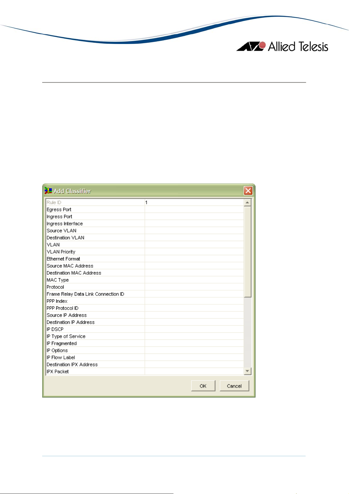
To add a new instance of a QoS element, click on the Add button to display the
Add window.
The Add window is presented as a two-column table (Property Sheet). The left
column represents the available fields for the QoS element, while the right
column represents their corresponding values.
During an Add operation, all field values are initially blank.
AlliedView™-EMS 3.10 QoS Manager User’s Guide Page 12 of 128
Page 13

To configure a field, click on the value cell of that field. Depending on the field
being configured, the value cell will become one of the following:
• Editable - a value is keyed in manually
• Dropdown Selection - a single value is selected from a pre-defined list of
values
• Editable Dropdown Selection - a single value can either be selected from
a pre-defined list of values or keyed in manually
• Multiple Selection - one or more values can be selected from a pre-
defined list of values. To select multiple contiguous values, hold down the
Shift key while selecting items from the list. To select multiple noncontiguous values, hold down the Ctrl key while selecting items from the
list.
After setting all the desired fields, you can complete the Add operation by
clicking the OK button.
If you wish to cancel the operation, click on the Cancel button.
4 Basic Operations
AlliedView™-EMS 3.10 QoS Manager User’s Guide Page 13 of 128
Page 14
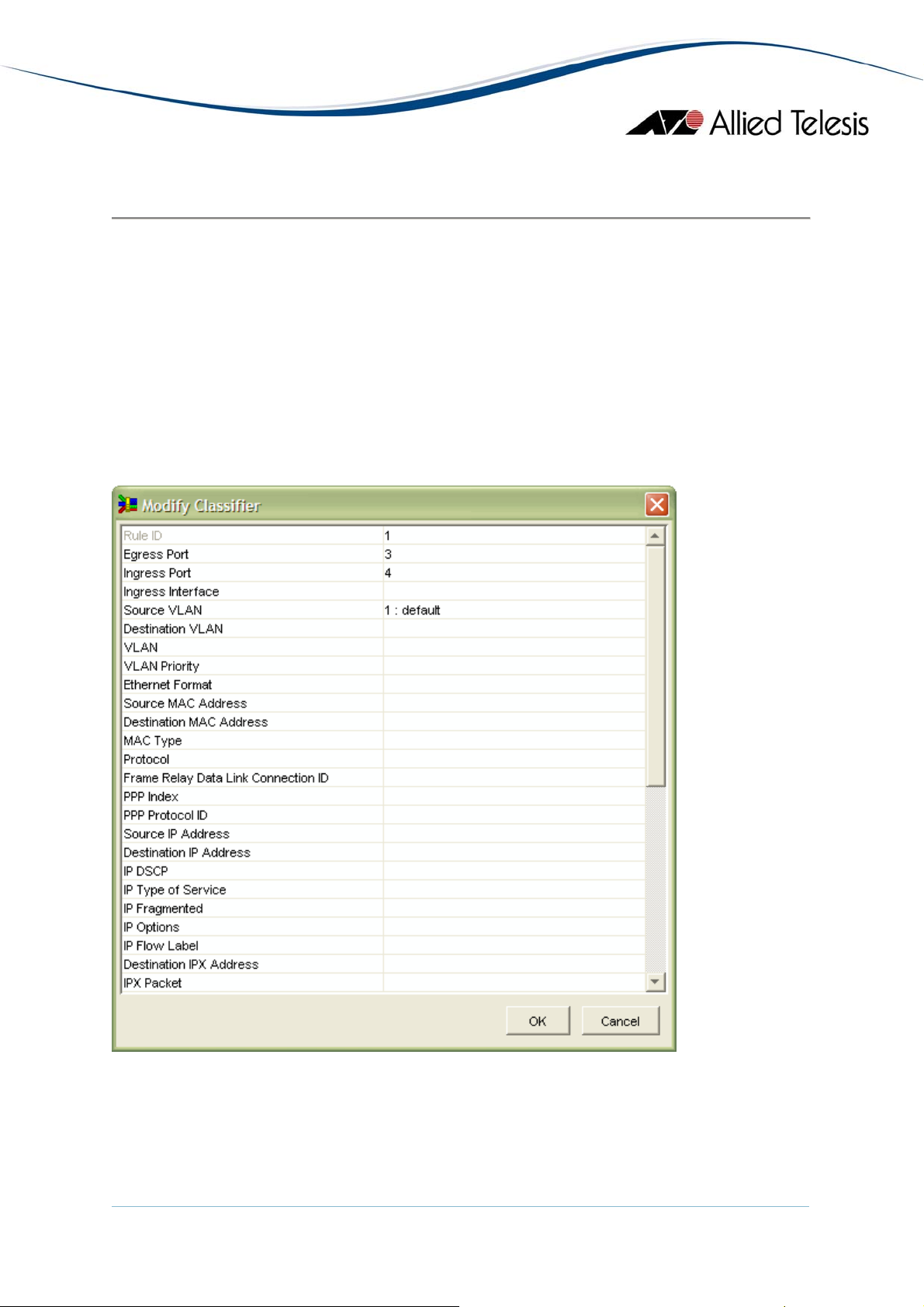
4.2 Modify
The Modify operation is only available on QoS-based devices and only for the
following QoS elements:
• Classifiers
• Flow Groups
• Traffic Classes
• Policies
To modify the field values of an existing instance of a QoS element, select a
table row from the QoS Information Window then click on the Modify button.
The Modify window is the same as the Add window except that the value cells
will now contain the values which were previously set.
The procedure for modifying a field value is the same as that used in the Add
operation.
AlliedView™-EMS 3.10 QoS Manager User’s Guide Page 14 of 128
Page 15

After modifying or setting all the desired fields, you can complete the Modify
operation by clicking the OK button.
If you wish to cancel the operation without applying the changes, click on the
Cancel button.
4 Basic Operations
AlliedView™-EMS 3.10 QoS Manager User’s Guide Page 15 of 128
Page 16

4.3 Delete
The Delete operation is only available on QoS-based devices and only for the
following QoS elements:
• Classifiers
• Flow Groups
• Traffic Classes
• Policies
To delete an instance of a QoS element, select a table row from the QoS
Information Window then click on the Delete button.
As a safety measure, before the selected element is deleted, you will be asked to
confirm the action.
4 Basic Operations
AlliedView™-EMS 3.10 QoS Manager User’s Guide Page 16 of 128
Page 17

4.4 Inline Table Editing
Inline table editing is available for both QoS-based and CoS-based devices. It
makes it relatively easy to manipulate table data directly on-screen without
having to use a Submit button or to go into some kind of 'edit' mode. For QoSbased devices, inline table editing is used to configure table fields in the Add and
Modify operations as well as in the Ports and Scheduling tabs. For CoS-based
devices, inline table editing is used to configure table fields in all tabs.
Inline table editing is similar to the process of configuring a field as described in
the Add operation. Refer to Section 4.1 - Add
Note - When modifying a field that contains a non-blank value to blank, the
following rules are observed:
.
• If "none" is a valid value, field will be set to "none".
• If "any" is a valid value, field will be set to "any".
• If neither "none" nor "any" is valid, field will be set to the last accepted
value for that field.
4 Basic Operations
AlliedView™-EMS 3.10 QoS Manager User’s Guide Page 17 of 128
Page 18
4.5 Apply
QoS/Cos configuration changes made through Add/Modify/Delete operations or
Inline Table Editing will not be immediately reflected on the device. QoS
Manager just stores these changes locally until an Apply operation is performed.
To apply QoS/CoS configuration changes to the device, click on the Apply button.
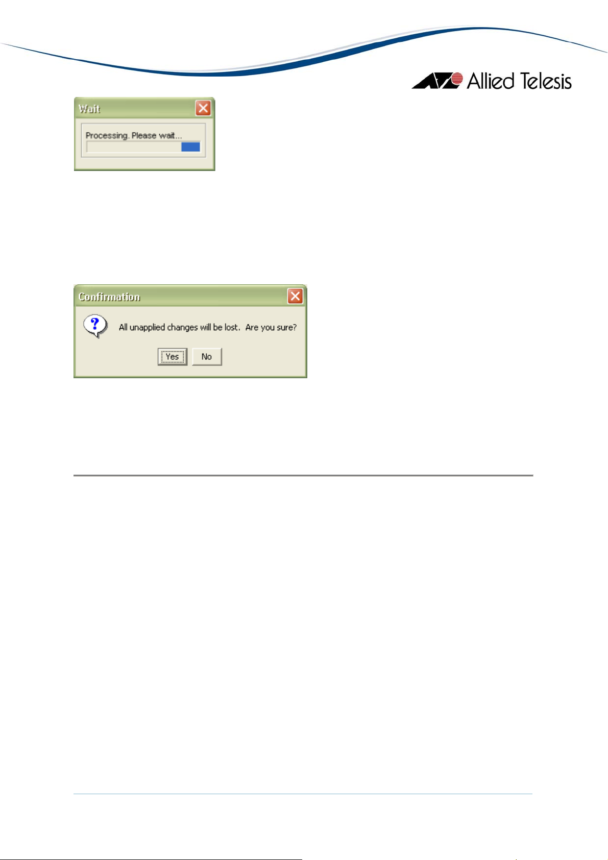
As a safety measure, before the operation is performed, you will be asked to
confirm the action.
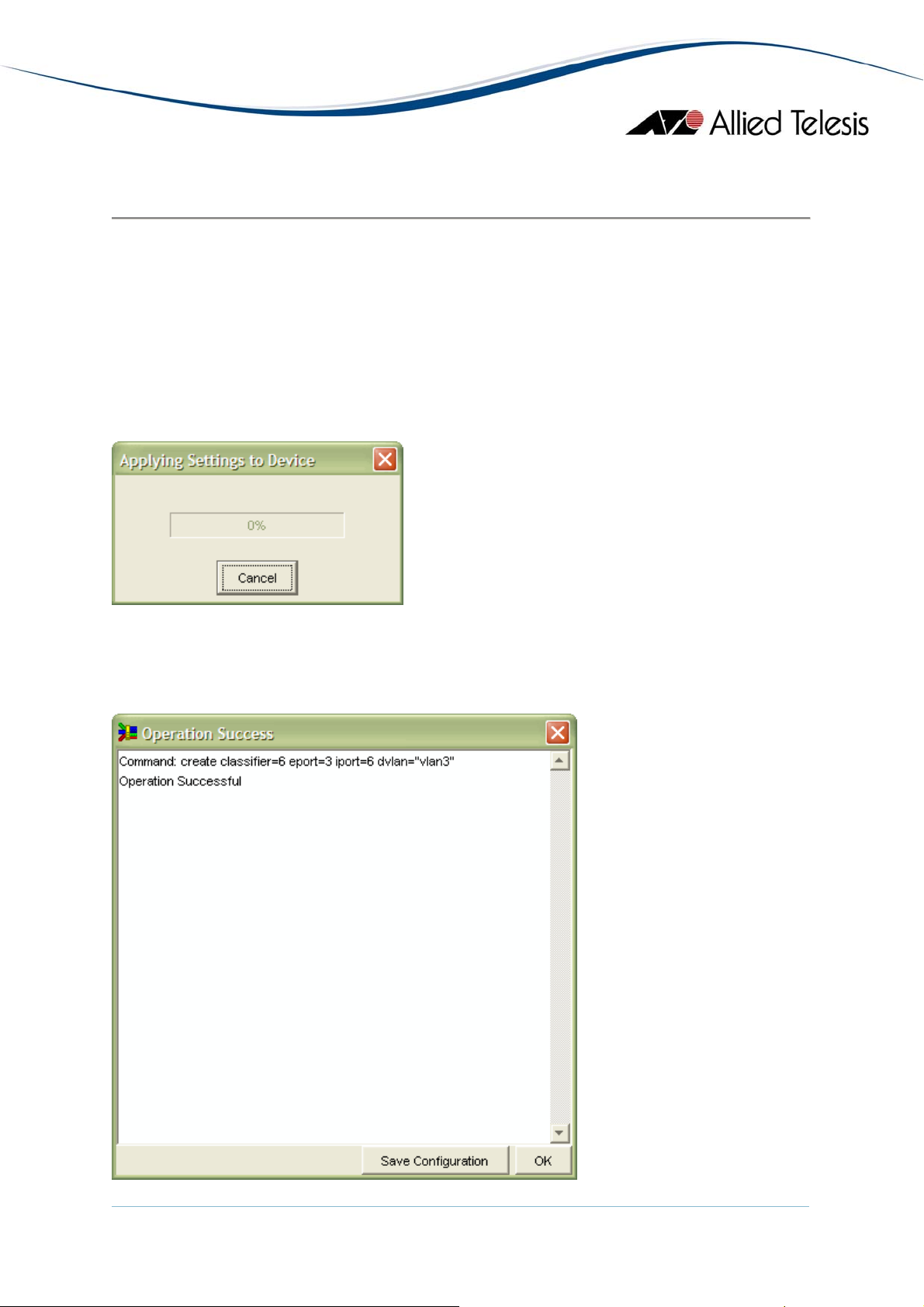
During the operation, a progress window will be displayed to indicate the status
of the operation. At any point in time, you may cancel the operation by clicking
the Cancel button.
AlliedView™-EMS 3.10 QoS Manager User’s Guide Page 18 of 128
Page 19

When the operation is completed, a Results/Summary window will be displayed.
This window will indicate whether the operation was successful or not. Also, this
window will display a log of the commands that were issued to the device in the
course of the operation.
If the operation was successful, the Save Configuration button will be enabled to
allow you to save the applied changes to the configuration file of the device.
To close the Results/Summary window, click on the OK button.
After the Results/Summary window closes, QoS Manager will perform a refresh
operation by retrieving the QoS/CoS Settings from the device. This is done to
ensure that the settings between the device and QoS Manager are synchronized.
4 Basic Operations
AlliedView™-EMS 3.10 QoS Manager User’s Guide Page 19 of 128
Page 20

5 Menus
This chapter describes the items on QoS Manager's main menu.
Topics:
• File
• Tools
• Help
5 Menus
AlliedView™-EMS 3.10 QoS Manager User’s Guide Page 20 of 128
Page 21
5.1 File
The File menu lets you connect to and disconnect from a target host, check the
properties of the target host, or exit QoS Manager.
Topics:
• Open
• Close
• Exit
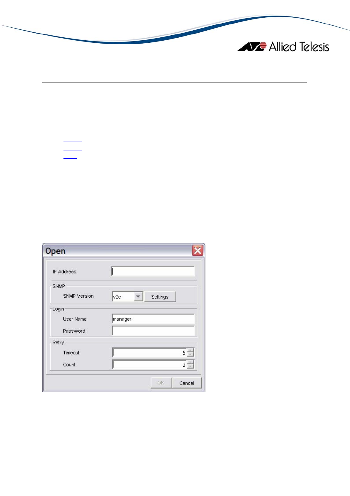
5.1.1 Open
This option allows you to specify a target host to connect to. When you select
File > Open, the following dialog box appears. To connect to the device, fill in
parameters in the dialog box, and click OK.
Note - This option is not available if QoS Manager is already connected to a
target host.
Open dialog box
IP Address
This is the Host Name or IP Address of the target host.
AlliedView™-EMS 3.10 QoS Manager User’s Guide Page 21 of 128
Page 22
SNMP
Version
This drop down list allows you to select the SNMP version to use in
managing the target device.
Note - Before choosing "v2c" or "v3", make sure that the target device
you are connecting to supports SNMP v2c and/or SNMP v3 respectively.
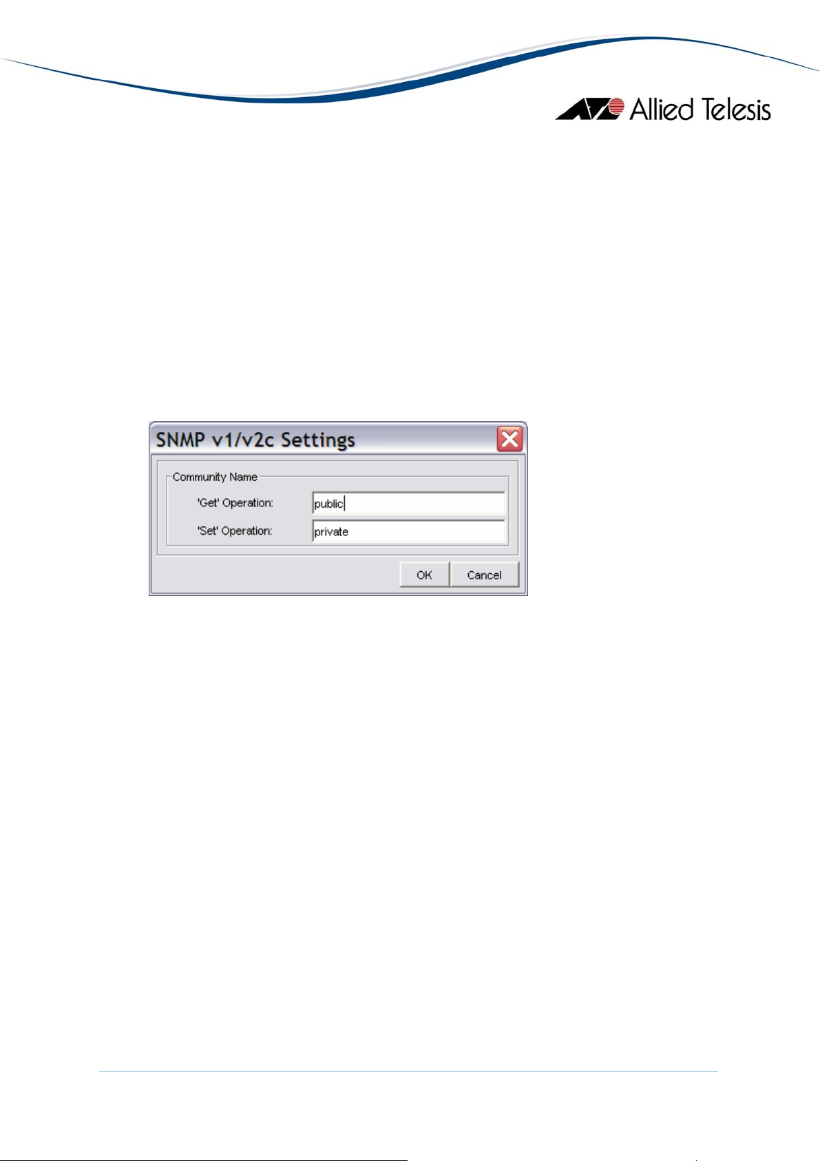
Settings
If the Version is set to "v1" or "v2c", this button opens the SNMP v1/v2c
Settings window. Otherwise, if the Version is set to "v3", this button
opens the SNMP v3 Settings window.
SNMP v1/v2c Settings dialog box
Community Name
The community strings to use in performing SNMP operations on the
target host. There are two types of community strings for SNMP. Be sure
to specify strings which match the ones configured on the target host.
By default, the following strings are used:
for the 'Get' operation
public
for the 'Set' operation
private
AlliedView™-EMS 3.10 QoS Manager User’s Guide Page 22 of 128
Page 23
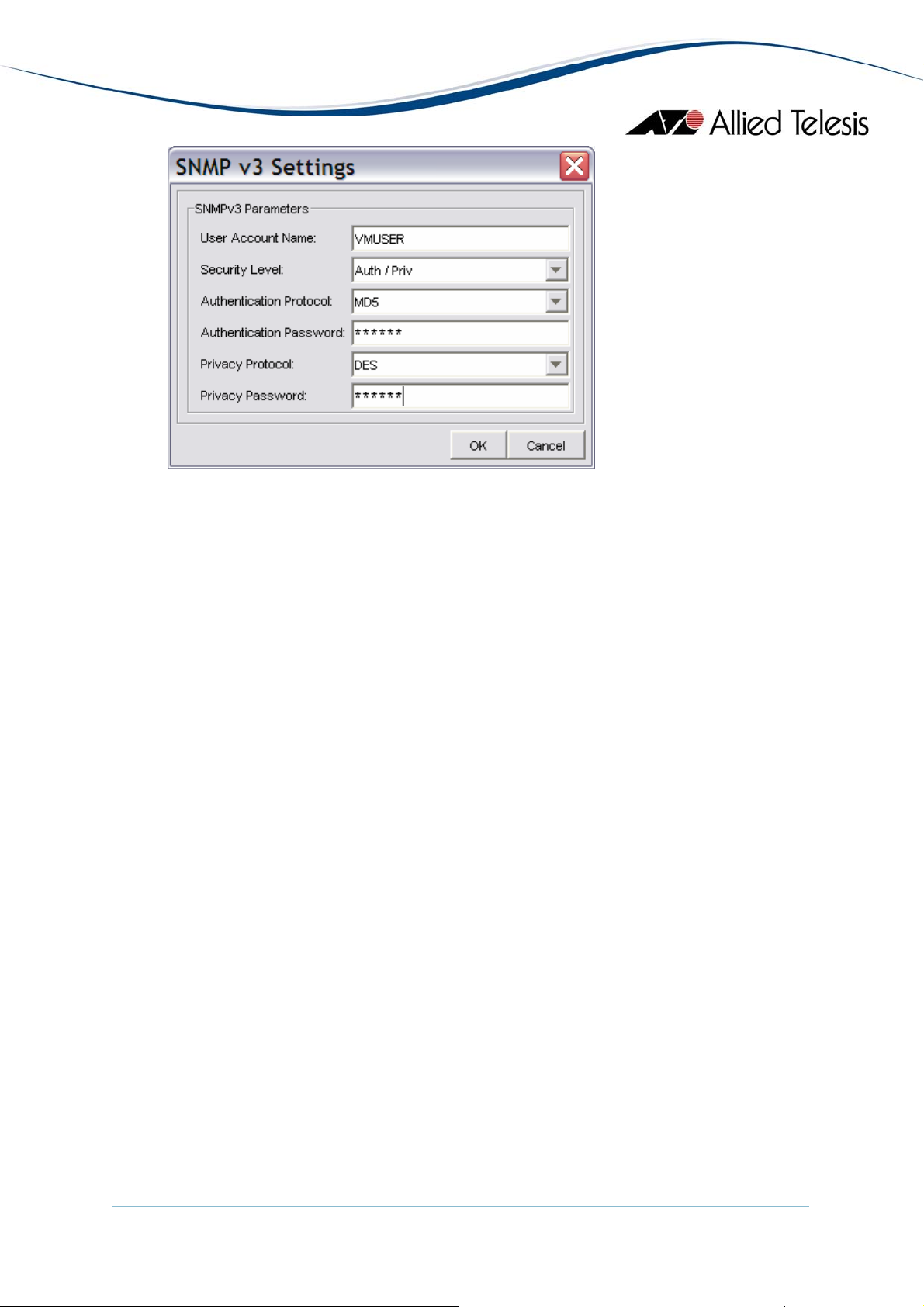
SNMP v3 Settings dialog box
User Account Name
This is the SNMPv3 User Account to be used for accessing the MIB of the
target device. Make sure to specify a User Account that has already been
configured on the target device.
Security Level
This is the Security Level for the User Account Name that you have
specified. Make sure to set the Security Level that is configured for the
User Account Name on the target device.
These are the available Security Levels:
No Auth / No Priv
This Security Level uses no authentication and no privacy.
Auth / No Priv
This Security Level uses authentication without privacy.
Auth / Priv
This Security Level uses authentication and privacy.
Authentication Protocol
If the Security Level is "Auth / No Priv" or "Auth / Priv", you need to
specify an Authentication Protocol that is configured for the User
Account Name on the target device.
These are the available Authentication Protocols:
MD5
Use HMAC-MD5-96 protocol
AlliedView™-EMS 3.10 QoS Manager User’s Guide Page 23 of 128
Page 24

Login
Retry
SHA
Use HMAC-SHA-96 protocol
Authentication Password
If the Security Level is "Auth / No Priv" or "Auth / Priv", you need to
specify an Authentication Password that is configured for the User
Account Name on the target device.
Privacy Protocol
If the Security Level is "Auth / Priv", you need to specify a Privacy
Protocol. This is the available Privacy Protocol:
DES
Use Data Encryption Standard
Privacy Password
If the Security Level is "Auth / Priv", you need to specify a Privacy
Password that is configured for the User Account Name on the target
device.
User Name
This is the account name to be used to log in to the device. By default,
this field is set to manager.
Password
This is the password for the account to be used.
Timeout
The number of seconds QoS Manager waits before it determines that the
device is not responding. By default, this value is set to 5 seconds.
Count
The number of times QoS Manager sends SNMP messages to the agent
before giving up. By default, this value is set to 2 retries.
5.1.2 Close
This option closes the active connection with the device and empties the
QoS/CoS Information Window.
Note - This option is not available if QoS Manager is not yet connected to a
device.
AlliedView™-EMS 3.10 QoS Manager User’s Guide Page 24 of 128
Page 25

5.1.3 Exit
This option terminates connection to the target host and closes the QoS
Manager application.
5 Menus
AlliedView™-EMS 3.10 QoS Manager User’s Guide Page 25 of 128
Page 26
5.2 Tools
The Tools menu lets you refresh the contents of the QoS/CoS Information
Window and restart the currently connected device. It also provides a quick
method for configuring QoS specifically for voice and video.
Topics:
• Quick Setup
• Refresh
• Reboot
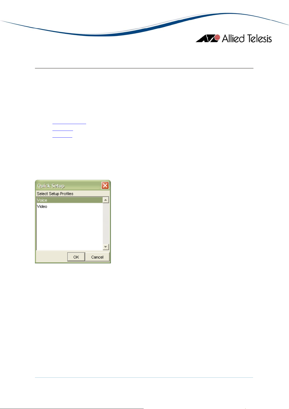
5.2.1 Quick Setup
Quick Setup provides a two-step process for creating a simple QoS
configuration for voice and/or video on the target device.
At the start of the Quick Setup, you will be prompted to select from two
profiles:
• Voice - Contains default settings suitable for Voice (VoIP) type
applications.
• Video - Contains default settings suitable for Video streaming
applications.
After selecting a Quick Setup profile, click OK to proceed to the next step.
AlliedView™-EMS 3.10 QoS Manager User’s Guide Page 26 of 128
Page 27
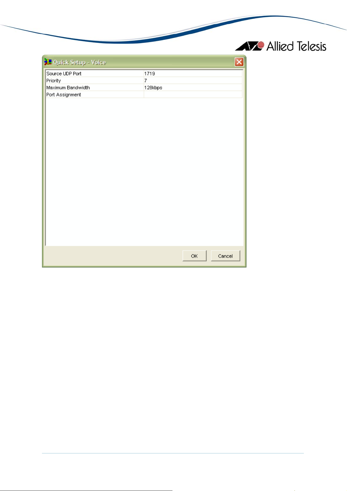
You will now be presented with default settings that you may adjust or fine-tune
depending on the requirements of your network.
After you complete the adjustments, click OK to complete the setup.
AlliedView™-EMS 3.10 QoS Manager User’s Guide Page 27 of 128
Page 28
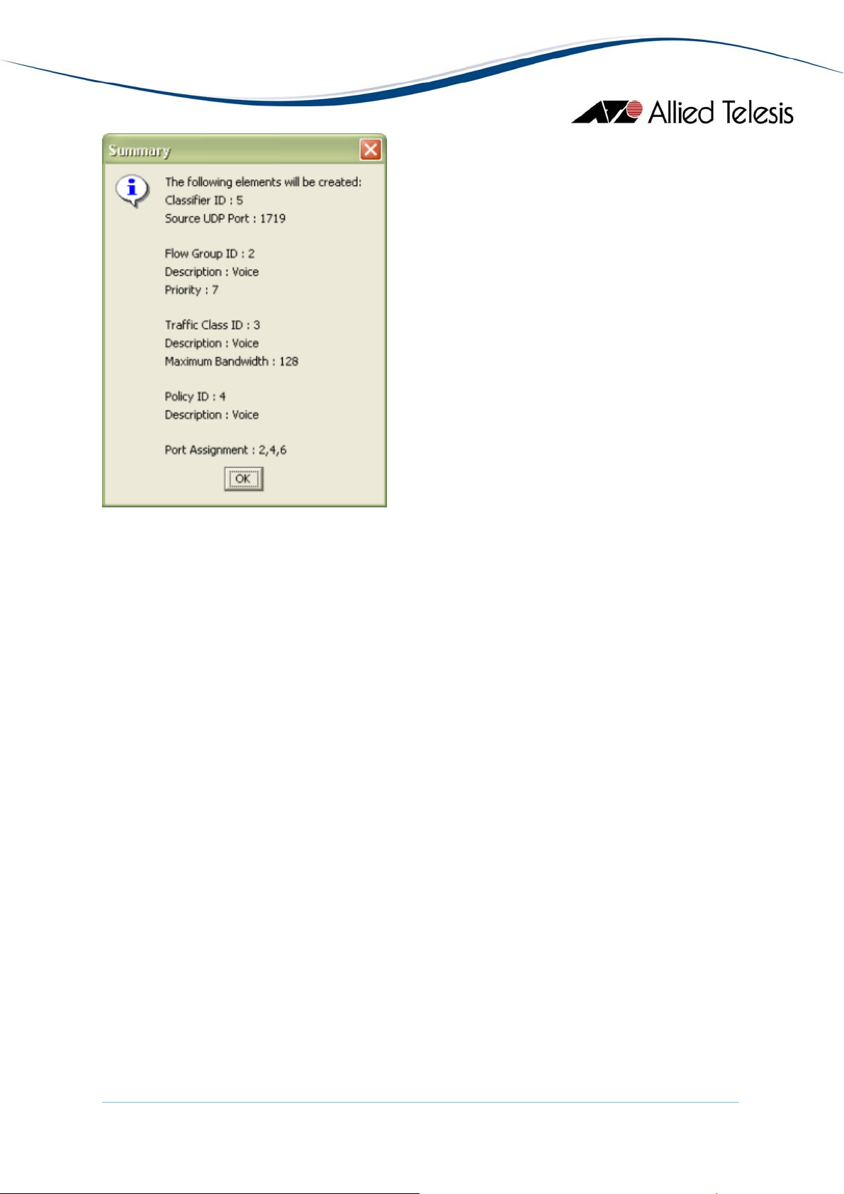
A Summary window will be displayed. The Summary window will contain a list
of QoS elements and settings that will be created by the Quick Setup function.
After confirming the message, you will be returned to the QoS Information
Window where you can do further revisions to or fine-tuning on the newly
created QoS elements.
Note that the Quick Setup function is only available for QoS-based devices.
5.2.2 Refresh
The Refresh operation will force QoS Manager to retrieve all QoS/CoS
configurations from the device. Note that performing a Refresh operation will
wipe out any settings which have not yet been applied to the device.
Before a Refresh operation is performed, you will be prompted with a
confirmation box. Upon confirmation, the refresh will start. While the Refresh
operation is in progress, a progress window will be displayed. Once completed,
the progress window will close and the contents of the QoS/CoS Information
Window will now be updated with the latest settings from the device.
Note that the Refresh operation is only available if QoS Manager is already
connected to a target host.
AlliedView™-EMS 3.10 QoS Manager User’s Guide Page 28 of 128
Page 29
5.2.3 Reboot
This option displays a reboot confirmation dialog box.
Note - This option is only available if QoS Manager is already connected to a
target host.
Upon confirmation, the device will be rebooted. While the Reboot is in progress,
a progress window will be displayed. Once completed, the progress window will
close and the contents of the QoS/CoS Information Window should now be
updated with the latest settings from the device.
5 Menus
AlliedView™-EMS 3.10 QoS Manager User’s Guide Page 29 of 128
Page 30

5.3 Help
The Help menu lets you view the online user's guide as well as some basic
information about the application.
Topics:
• Index
• About
5.3.1 Index
This option displays the main page of the online user's manual.
5.3.2 About
This option displays version and copyright information for QoS Manager. It also
displays a list of the currently supported devices.
5 Menus
AlliedView™-EMS 3.10 QoS Manager User’s Guide Page 30 of 128
Page 31

6 Device Support
This section describes, on a per device series basis, the specific QoS/CoS
attributes displayed in the QoS/CoS Information Window, the configurable
fields available in the Add, Modify and Quick Setup windows, and any known
issues and/or operational notes.
Topics:
• AT-8000S Series
• AT-8600 Series
• AT-8800 Series
• AT-9000/24
• AT-9400 Series
• AT-9900 Series
• AT-x900-24x Series
• Rapier 24i
• SwitchBlade Series
6 Device Support
AlliedView™-EMS 3.10 QoS Manager User’s Guide Page 31 of 128
Page 32

6.1 AT-8000S Series
Topics:
• General
• Port
• Scheduling
• CoS Priority
• DSCP Priority
• Bandwidth
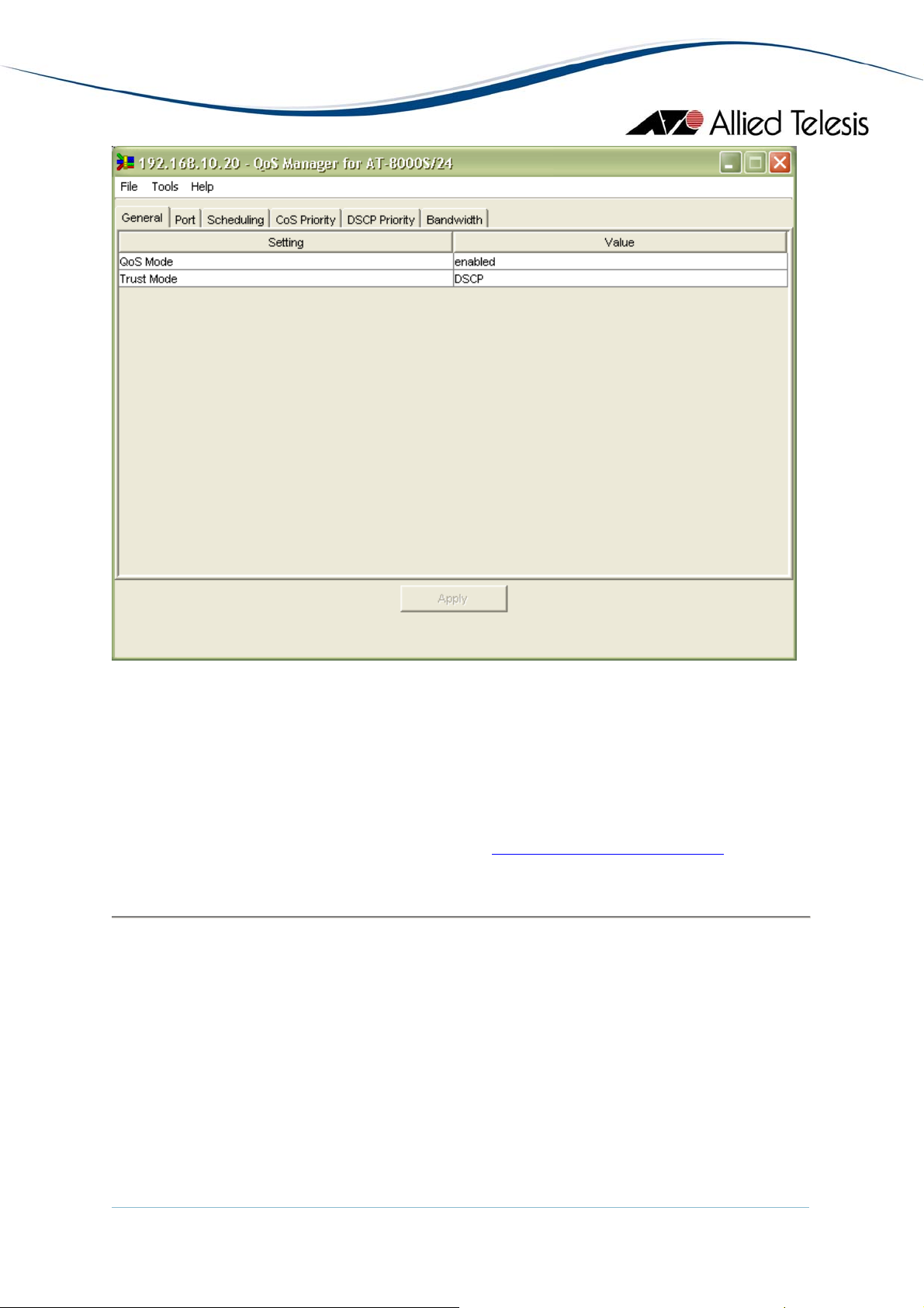
6.1.1 General
Setting Description Value
QoS Mode Enables/Disables quality of
service (QoS) on the device
Trust Mode Configures the system to the
• enabled
• disabled
• CoS - ingress packets are
basic mode and trust state. It is
used to specify whether the
ports are trusted and which
field of the ingress packets to
use to classify traffic.
• DSCP - ingress packets
6.1.2 Port
Column Name Description Value
Interface
(cannot be
modified)
Lists the interfaces (ports and
channels) available
The available interfaces will
depend on the device model
and configuration.
• standalone - e1, e2..en
• stacked - 1/e1, 1/e2..1/en,
• channels - ch1, ch2..chn
classified using packet
CoS values. Untagged
packets are classified
using the default port
CoS value.
are classified using
packet DSCP values
2/e1, 2/e2..s/en
where:
• n = port/channel number
• s = stack id
AlliedView™-EMS 3.10 QoS Manager User’s Guide Page 32 of 128
Page 33

Default CoS Specifies the default CoS value
Range: 0-7
of an interface
6.1.3 Scheduling
Setting Description Value
Scheduling Configures the number of
• Strict Priority - higher
expedite queues. It is used to
specify the scheduling method
to use.
• Weighted Priority -
6.1.4 CoS Priority
priority queues are
emptied before any
packets are transmitted
from lower priority
queues
packets are transmitted
from all queues in a
round-robin fashion
based on the queue
weights
Column Name Description Value
Class of Service
Lists the CoS values available Range: 0-7
(cannot be
modified)
Queue Specifies the queue number to
Range: 1-4
which the CoS value is mapped
6.1.5 DSCP Priority
Column Name Description Value
DSCP
Lists the DSCP values available Range: 0-63
(cannot be
modified)
Queue Specifies the queue number to
Range: 1-4
which the DSCP value is
mapped
6.1.6 Bandwidth
Column Name Description Value
Interface
(cannot be
modified)
Lists the interfaces (ports and
channels) available
The available interfaces will
depend on the device model
and configuration.
• standalone - e1, e2..en
• stacked - 1/e1, 1/e2..1/en,
2/e1, 2/e2..s/en
AlliedView™-EMS 3.10 QoS Manager User’s Guide Page 33 of 128
Page 34

Column Name Description Value
• channels - ch1, ch2..chn
where:
• n = port/channel number
• s = stack id
Ingress Status Enables/Disables the Rate Limit
field
• enabled
• disabled
Rate Limit Specifies the maximum kilobits
Range: 62-1000000
per second of ingress traffic on
a port
Note - This field does not apply
to channels.
Egress Status Enables/Disables the CIR field • enabled
• disabled
CIR Sets the average traffic rate in
Range: 64-1000000
kilobits per second and enables
the CBS field
CBS Sets the excess burst size in
Range: 4096-16769020
bytes. This field remains
disabledif CIR field is empty
Note - This field applies to
combo ports and channels only.
6 Device Support
AlliedView™-EMS 3.10 QoS Manager User’s Guide Page 34 of 128
Page 35

6.2 AT-8600 Series
Topics:
• Classifiers
• Flow Groups
• Traffic Classes
• Policies
• Ports
• Scheduling
• Quick Setup
• Notes
6.2.1 Classifiers
6.2.1.1 QoS Information Window
Column Name Description
Classifier ID Lists the Rule ID of packet-matching rules
available
6.2.1.2 Add/Modify Classifier
Property
Name
Rule ID
(cannot be
modified)
VLAN Specifies the Destination
Egress Port Specifies the egress port on the
Description Valid Values
Uniquely identifies the packet-
Range: 1-9999
matching rule
This can be set by selecting
VLAN that the packet will be
transmitted on.
from a list of available VLANs
or "any".
This can be set by selecting any
switch to match for each
of the following values:
frame.
• 1-N (where N is the
number of ports available
on the device)
Ingress Port Specifies the ingress port on
the switch to match for each
This can be set by selecting any
of the following values:
frame.
• 1-N (where N is the
number of ports available
on the device)
AlliedView™-EMS 3.10 QoS Manager User’s Guide Page 35 of 128
Page 36

Property
Name
Ethernet
Format
Source IP
Address
Description Valid Values
Specifies the Ethernet
encapsulation type of the
This can be set by selecting any
of the following values:
packet.
• 802.2
• 802.2-Tagged
• 802.2-Untagged
• EthII
• EthII-Tagged
• EthII-Untagged
• NetwareRaw
• NetwareRaw-Tagged
• NetwareRaw-Untagged
• SNAP
• any
Specifies the source IP Address
(either host or host/subnet) of
an IP packet.
This can be set by entering an
IP Address in dotted decimal
notation with an optional mask
Destination IP
Address
Specifies the destination IP
Address (either host or
host/subnet) of an IP packet.
IP DSCP This the Code Point bits of the
DiffServ field of an IP packet.
IP Protocol This specifies a Layer 4 IP
protocol of an IP packet.
• NNN.NNN.NNN.NNN
• NNN.NNN.NNN.NNN/M
Where M = 0-32
This can be set by entering an
IP Address in dotted decimal
notation with an optional mask
• NNN.NNN.NNN.NNN
• NNN.NNN.NNN.NNN/M
Where M = 0-32.
This can be set by entering one
or more integers from 0-63.
Input can be a comma
separated list or a range
(specified as m-n) or a
combination of both. (e.g. 2, 4-
7)
This value can also be set to
"any".
This can be set by selecting any
of the following values:
• TCP
AlliedView™-EMS 3.10 QoS Manager User’s Guide Page 36 of 128
Page 37

Property
Name
IP Type of
Service
Description Valid Values
Specifies the value of the
precedence field within the
TOS (Type of Service) byte of
an IP packet.
Destination
IPX Address
Specifies the destination
network address of an IPX
packet.
IPX Packet Specifies the value of the
Packet Type field of an IPX
packet.
• UDP
• ICMP
• IGMP
• any
This can also be set by entering
an integer from 0-255.
Range: any, 0-7
This can be set by entering a 4-
byte hexadecimal value.
(00000001-FFFFFFFF)
This can also be set to "any".
This can be set by entering a 2-
byte hexadecimal value (00-FF)
or selecting from the following:
Source IPX
Socket
Specifies the source IPX socket
number of an IPX packet.
• NLSP
• RIP
• SAP
• SPX
• NCP
• NETBIOS
• any
This can be set by entering a 2-
byte hexadecimal value (0000-
FFFF) or by selecting one of the
following:
• NCP
• SAP
• RIP
• NNB
• DIAG
• NLSP
• IPXWAN
• any
Destination
IPX Socket
AlliedView™-EMS 3.10 QoS Manager User’s Guide Page 37 of 128
Specifies the destination IPX
socket number of an IPX
packet.
This can be set by entering a 2-
byte hexadecimal value (0000-
FFFF) or by selecting one of the
Page 38

Property
Name
Source MAC
Address
Destination
MAC Address
Description Valid Values
following:
• NCP
• SAP
• RIP
• NNB
• DIAG
• NLSP
• IPXWAN
• any
Specifies the source MAC
address of the packet.
This can be set by entering a
MAC address string using the
following format:
• XX-XX-XX-XX-XX-XX
This can also be set to "any".
This parameter specifies the
destination MAC address of the
packet.
This can be set by entering a
MAC address string using the
following format:
Match1 Specifies the actual data to
match
Mask1 Specifies whether the
corresponding bit in the
Match1 parameter is "on" for a
match or "don't care" for a
match.
Offset1 Specifies the location or offset
where the pattern for Match1
is to be checked.
Match2 Specifies the actual data to
match
Mask2 Specifies whether the
corresponding bit in the
Match2 parameter is "on" for a
match or "don't care" for a
match.
Offset2 Specifies the location or offset
where the pattern for Match2
• XX-XX-XX-XX-XX-XX
This can also be set to "any".
This can be set by entering a 2-
byte hex number. (0000-FFFF)
This can be set by entering a 2-
byte hex number. (0000-FFFF)
Range: 0-62
This can be set by entering a 2-
byte hex number. (0000-FFFF)
This can be set by entering a 2-
byte hex number. (0000-FFFF)
Range: 0-62
AlliedView™-EMS 3.10 QoS Manager User’s Guide Page 38 of 128
Page 39

Property
Name
Description Valid Values
is to be checked.
Match3 Specifies the actual data to
match
Mask3 Specifies whether the
corresponding bit in the
Match3 parameter is "on" for a
match or "don't care" for a
match.
Offset3 Specifies the location or offset
where the pattern for Match3
is to be checked.
Protocol Specifies the protocol of the
packet.
This can be set by entering a 2-
byte hex number. (0000-FFFF)
This can be set by entering a 2-
byte hex number. (0000-FFFF)
Range: 0-62
This can be set by selecting any
of the following values:
• IP
• IPv6
• ARP
• IPX
• NONIPIPX
• any
Source TCP
Port
Destination
TCP Port
Specifies the TCP source port
of a TCP/IP packet.
Specifies the TCP destination
port of a TCP/IP packet.
TCP Flags Specifies the TCP flags of a
TCP/IP packet.
Source UDP
Port
Destination
UDP Port
Specifies the UDP source port
of an UDP/IP packet.
Specifies the UDP destination
port of an UDP/IP packet.
This can also be set by entering
a 1- to 5- byte hexadecimal
value (00-FFFFFFFFFF).
Range: any, 0-65535
Range: any, 0-65535
This can be set by selecting one
or more of the following values:
• URG
• ACK
• RST
• SYN
• FIN
• any
Range: any, 0-65535
Range: any, 0-65535
AlliedView™-EMS 3.10 QoS Manager User’s Guide Page 39 of 128
Page 40

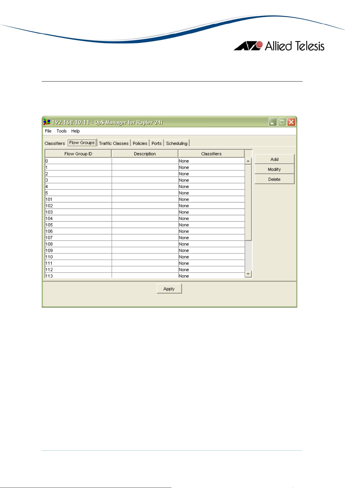
6.2.2 Flow Groups
6.2.2.1 QoS Information Window
Column Name Description
Flow Group ID Lists the ID of Flow Groups available
Description A brief description of the Flow Group.
Classifiers List of Classifiers associated with this Flow
Group
6.2.2.2 Add/Modify Flow Group
Property Name Description Valid Values
Flow Group ID
(cannot be
Specifies the unique identifier
for the flow group.
modified)
Description Specifies a brief description of
the Flow Group.
Mark Value This parameter specifies a
replacement value to write into
the DSCP (TOS) field for all
packets.
Priority This parameter specifies the
priority that traffic belonging to
this Flow Group has.
Remark
Priority
Specifies whether the value of
the priority parameter is used
to set the egress queue
selection for a frame and also
to replace the 802.1p priority
value in the frame, or just to
select the egress queue for the
frame.
Classifier List Specifies a list of the Classifiers
currently assigned to this Flow
Group.
Range: 0-1023
To set this value, enter an
alphanumeric string from 1-15
characters.
Range: none, 0-63
Range: none, 0-7
• yes
• no
Select from a list of available
classifier IDs.
6.2.3 Traffic Classes
6.2.3.1 QoS Information Window
Column Name Description
Traffic Class ID Lists the ID of Traffic Classes available
Description A brief description of the Traffic Class
Flow Groups List of the Flow Groups associated with this
Traffic Class
AlliedView™-EMS 3.10 QoS Manager User’s Guide Page 40 of 128
Page 41

6.2.3.2 Add/Modify Traffic Class
Property Name Description Valid Values
Traffic Class ID
(cannot be
Specifies the unique identifier
for this Traffic Class.
modified)
Description Specifies a brief description of
the Traffic Class.
Exceed Action Specifies the action to take if
the traffic classes
maxbandwidth is exceeded.
Exceed Remark
Value
Specifies the DSCP
replacement value for traffic
that exceeds the
maxbandwidth.
Mark Value Specifies a replacement value
to write into the DSCP (TOS)
field for all packets.
Maximum
Bandwidth
Specifies the maximum
bandwidth available to the
traffic class.
Range: 0-511
To set this value, enter an
alphanumeric string from 1-15
characters.
• drop
• remark
Range: 0-63
Range: none, 0-63
This can be set by entering a
value using one the following
formats:
Priority Specifies the priority value in
the IEEE Standard 802.1p tag
control field that traffic
belonging to this traffic class is
assigned.
Remark
Priority
Specifies whether the value of
the priority parameter is used
to set the egress queue
selection for a frame and also
to replace the 802.1p priority
value in the frame, or just to
select the egress queue for the
frame.
Flow Group
List
Specifies a list of the Flow
Groups currently assigned to
this Traffic Class.
• 0-16000000 kbps
• 0-16000 Mbps (decimal
point supported)
• 0-16 Gbps (decimal point
supported)
Range: none, 0-7
• yes
• no
Select from a list of available
Flow Group IDs.
AlliedView™-EMS 3.10 QoS Manager User’s Guide Page 41 of 128
Page 42

w
6.2.4 Policies
6.2.4.1 QoS Information Window
Column Name Description
Policy ID Lists the ID of Policies available
Description A brief description of the Policy
Traffic Classes List of Traffic Classes associated with this Policy
6.2.4.2 Add/Modify Policy
Property Name Description Valid Values
Policy ID
(cannot be
Specifies the unique identifier
for the Policy.
modified)
Description Specifies a brief description of
the Policy.
Ingress DSCP
Overwrite
Specifies the DSCP value used
to overwrite the DSCP value
on the ingress queue.
Remark Ingress
DSCP
Specifies the conditions under
hich the ingress DSCP value is
overwritten.
Range: 0-255
To set this value, enter an
alphanumeric string from 1-15
characters.
Range: none, 0-63
• zero
• all
• none
Traffic Class
List
Specifies a list of the Traffic
Classes currently assigned to
Select from a list of available
Traffic Class IDs.
this Policy.
6.2.5 Ports
Column Name Description Valid Values
Port
(cannot be
Lists the ports available Available ports will depend on
the device model
modified)
Policy Specifies the policy to associate
with the port
Select from a list of available
policies
6.2.6 Scheduling
Column Name Description Valid Values
Queue
(cannot be
modified)
Max Packets
Lists the hardware CoS queues
available. Range: 0-3
Maximum number of packets
able to be transmitted from
Range: 0-255
this queue before the control is
AlliedView™-EMS 3.10 QoS Manager User’s Guide Page 42 of 128
Page 43

passed to the next queue.
Maximum permissible elapsed
Max Latency
time between packets
Range: 0, 16-4080
transmitted from this queue.
6.2.7 Quick Setup
Property Name Description Valid Values
Source UDP
Port
Priority Specifies the priority that will
Maximum
Bandwidth
Specifies the UDP source port
of an UDP/IP packet.
be assigned for this setup.
Specifies the maximum
bandwidth available to this
setup.
Range: 0-65535
Default for VOICE: 1719
Default for VIDEO: 1024
Range: none, 0-7
Default for VOICE: 7
Default for VIDEO: 4
• 0-16000000 kbps
• 0-16000 Mbps (decimal
point supported)
• 0-16 Gbps (decimal point
supported)
Default for VOICE: 128kbps
Default for VIDEO: 256kbps
Port
Assignment
Specifies a list of ports that will
be affected by this setup.
Select from a list of available
Ports.
Default for VOICE: no ports
Default for VIDEO: no ports
6.2.8 Notes
• Values entered for the Max Bandwidth traffic class property are rounded
to the nearest 1000kbps.
8 Device Support
AlliedView™-EMS 3.10 QoS Manager User’s Guide Page 43 of 128
Page 44

6.3 AT-8800 Series
Topics:
• Classifiers
• Flow Groups
• Traffic Classes
• Policies
• Ports
• Scheduling
• Quick Setup
• Notes
6.3.1 Classifier
6.3.1.1 QoS Information Window
Column Name Description
Classifier ID Lists the Rule ID of packet-matching rules
available
6.3.1.2 Add/Modify Classifier
Property
Name
Rule ID
(cannot be
modified)
VLAN Specifies the Destination
Egress Port Specifies the egress port on the
Description Valid Values
Uniquely identifies the packet-
Range: 1-9999
matching rule
This can be set by selecting
VLAN that the packet will be
transmitted on.
from a list of available VLANs
or "any".
This can be set by selecting any
switch to match for each
of the following values:
frame.
• 1-N (where N is the
number of ports available
on the device)
Ingress Port Specifies the ingress port on
the switch to match for each
This can be set by selecting any
of the following values:
frame.
• 1-N (where N is the
number of ports available
on the device)
AlliedView™-EMS 3.10 QoS Manager User’s Guide Page 44 of 128
Page 45

Property
Name
Ethernet
Format
Source IP
Address
Description Valid Values
Specifies the Ethernet
encapsulation type of the
This can be set by selecting any
of the following values:
packet.
• 802.2
• 802.2-Tagged
• 802.2-Untagged
• EthII
• EthII-Tagged
• EthII-Untagged
• NetwareRaw
• NetwareRaw-Tagged
• NetwareRaw-Untagged
• SNAP
• any
Specifies the source IP Address
(either host or host/subnet) of
an IP packet.
This can be set by entering an
IP Address in dotted decimal
notation with an optional mask
Destination IP
Address
Specifies the destination IP
Address (either host or
host/subnet) of an IP packet.
IP DSCP This the Code Point bits of the
DiffServ field of an IP packet.
IP Protocol This specifies a Layer 4 IP
protocol of an IP packet.
• NNN.NNN.NNN.NNN
• NNN.NNN.NNN.NNN/M
Where M = 0-32
This can be set by entering an
IP Address in dotted decimal
notation with an optional mask
• NNN.NNN.NNN.NNN
• NNN.NNN.NNN.NNN/M
Where M = 0-32.
This can be set by entering one
or more integers from 0-63.
Input can be a comma
separated list or a range
(specified as m-n) or a
combination of both. (e.g. 2, 4-
7)
This value can also be set to
"any".
This can be set by selecting any
of the following values:
• TCP
AlliedView™-EMS 3.10 QoS Manager User’s Guide Page 45 of 128
Page 46

Property
Name
IP Type of
Service
Description Valid Values
Specifies the value of the
precedence field within the
TOS (Type of Service) byte of
an IP packet.
Destination
IPX Address
Specifies the destination
network address of an IPX
packet.
IPX Packet Specifies the value of the
Packet Type field of an IPX
packet.
• UDP
• ICMP
• IGMP
• any
This can also be set by entering
an integer from 0-255.
Range: any, 0-7
This can be set by entering a 4-
byte hexadecimal value.
(00000001-FFFFFFFF)
This can also be set to "any".
This can be set by entering a 2-
byte hexadecimal value (00-FF)
or selecting from the following:
Source IPX
Socket
Specifies the source IPX socket
number of an IPX packet.
• NLSP
• RIP
• SAP
• SPX
• NCP
• NETBIOS
• any
This can be set by entering a 2-
byte hexadecimal value (0000-
FFFF) or by selecting one of the
following:
• NCP
• SAP
• RIP
• NNB
• DIAG
• NLSP
• IPXWAN
• any
Destination
IPX Socket
AlliedView™-EMS 3.10 QoS Manager User’s Guide Page 46 of 128
Specifies the destination IPX
socket number of an IPX
packet.
This can be set by entering a 2-
byte hexadecimal value (0000-
FFFF) or by selecting one of the
Page 47

Property
Name
Source MAC
Address
Destination
MAC Address
Description Valid Values
following:
• NCP
• SAP
• RIP
• NNB
• DIAG
• NLSP
• IPXWAN
• any
Specifies the source MAC
address of the packet.
This can be set by entering a
MAC address string using the
following format:
• XX-XX-XX-XX-XX-XX
This can also be set to "any".
This parameter specifies the
destination MAC address of the
packet.
This can be set by entering a
MAC address string using the
following format:
Match1 Specifies the actual data to
match
Mask1 Specifies whether the
corresponding bit in the
Match1 parameter is "on" for a
match or "don't care" for a
match.
Offset1 Specifies the location or offset
where the pattern for Match1
is to be checked.
Match2 Specifies the actual data to
match
Mask2 Specifies whether the
corresponding bit in the
Match2 parameter is "on" for a
match or "don't care" for a
match.
Offset2 Specifies the location or offset
where the pattern for Match2
• XX-XX-XX-XX-XX-XX
This can also be set to "any".
This can be set by entering a 2-
byte hex number. (0000-FFFF)
This can be set by entering a 2-
byte hex number. (0000-FFFF)
Range: 0-62
This can be set by entering a 2-
byte hex number. (0000-FFFF)
This can be set by entering a 2-
byte hex number. (0000-FFFF)
Range: 0-62
AlliedView™-EMS 3.10 QoS Manager User’s Guide Page 47 of 128
Page 48

Property
Name
Description Valid Values
is to be checked.
Match3 Specifies the actual data to
match
Mask3 Specifies whether the
corresponding bit in the
Match3 parameter is "on" for a
match or "don't care" for a
match.
Offset3 Specifies the location or offset
where the pattern for Match3
is to be checked.
Protocol Specifies the protocol of the
packet.
This can be set by entering a 2-
byte hex number. (0000-FFFF)
This can be set by entering a 2-
byte hex number. (0000-FFFF)
Range: 0-62
This can be set by selecting any
of the following values:
• IP
• IPv6
• ARP
• IPX
• NONIPIPX
• any
Source TCP
Port
Destination
TCP Port
Specifies the TCP source port
of a TCP/IP packet.
Specifies the TCP destination
port of a TCP/IP packet.
TCP Flags Specifies the TCP flags of a
TCP/IP packet.
Source UDP
Port
Destination
UDP Port
Specifies the UDP source port
of an UDP/IP packet.
Specifies the UDP destination
port of an UDP/IP packet.
This can also be set by entering
a 1- to 5- byte hexadecimal
value (00-FFFFFFFFFF).
Range: any, 0-65535 or a port
range (n-m).
Range: any, 0-65535 or a port
range (n-m).
This can be set by selecting one
or more of the following values:
• URG
• ACK
• RST
• SYN
• FIN
• any
Range: any, 0-65535 or a port
range (n-m).
Range: any, 0-65535 or a port
range (n-m).
AlliedView™-EMS 3.10 QoS Manager User’s Guide Page 48 of 128
Page 49

6.3.2 Flow Groups
6.3.2.1 QoS Information Window
Column Name Description
Flow Group ID Lists the ID of Flow Groups available
Description A brief description of the Flow Group.
Classifiers List of Classifiers associated with this Flow
Group
6.3.2.2 Add/Modify Flow Group
Property Name Description Valid Values
Flow Group ID
(cannot be
Specifies the unique identifier
for the flow group.
modified)
Description Specifies a brief description of
the Flow Group.
Mark Value This parameter specifies a
replacement value to write into
the DSCP (TOS) field for all
packets.
Priority This parameter specifies the
priority that traffic belonging to
this Flow Group has.
Remark
Priority
Specifies whether the value of
the priority parameter is used
to set the egress queue
selection for a frame and also
to replace the 802.1p priority
value in the frame, or just to
select the egress queue for the
frame.
Classifier List Specifies a list of the Classifiers
currently assigned to this Flow
Group.
Range: 0-1023
To set this value, enter an
alphanumeric string from 1-15
characters.
Range: none, 0-63
Range: none, 0-7
• yes
• no
Select from a list of available
classifier IDs.
6.3.3 Traffic Classes
6.3.3.1 QoS Information Window
Column Name Description
Traffic Class ID Lists the ID of Traffic Classes available
Description A brief description of the Traffic Class
Flow Groups List of the Flow Groups associated with this
Traffic Class
AlliedView™-EMS 3.10 QoS Manager User’s Guide Page 49 of 128
Page 50

6.3.3.2 Add/Modify Traffic Class
Property Name Description Valid Values
Traffic Class ID
(cannot be
Specifies the unique identifier
for this Traffic Class.
modified)
Description Specifies a brief description of
the Traffic Class.
Exceed Action Specifies the action to take if
the traffic classes
maxbandwidth is exceeded.
Exceed Remark
Value
Specifies the DSCP
replacement value for traffic
that exceeds the
maxbandwidth.
Mark Value Specifies a replacement value
to write into the DSCP (TOS)
field for all packets.
Maximum
Bandwidth
Specifies the maximum
bandwidth available to the
traffic class.
Range: 0-511
To set this value, enter an
alphanumeric string from 1-15
characters.
• drop
• remark
Range: 0-63
Range: none, 0-63
This can be set by entering a
value using one the following
formats:
Priority Specifies the priority value in
the IEEE Standard 802.1p tag
control field that traffic
belonging to this traffic class is
assigned.
Remark
Priority
Specifies whether the value of
the priority parameter is used
to set the egress queue
selection for a frame and also
to replace the 802.1p priority
value in the frame, or just to
select the egress queue for the
frame.
Flow Group
List
Specifies a list of the Flow
Groups currently assigned to
this Traffic Class.
• 0-16000000 kbps
• 0-16000 Mbps (decimal
point supported)
• 0-16 GBps (decimal point
supported)
Range: none, 0-7
• yes
• no
Select from a list of available
Flow Group IDs.
AlliedView™-EMS 3.10 QoS Manager User’s Guide Page 50 of 128
Page 51

w
6.3.4 Policies
6.3.4.1 QoS Information Window
Column Name Description
Policy ID Lists the ID of Policies available
Description A brief description of the Policy
Traffic Classes List of Traffic Classes associated with this Policy
6.3.4.2 Add/Modify Policy
Property Name Description Valid Values
Policy ID
(cannot be
Specifies the unique identifier
for the Policy.
modified)
Description Specifies a brief description of
the Policy.
Ingress DSCP
Overwrite
Specifies the DSCP value used
to overwrite the DSCP value
on the ingress queue.
Remark Ingress
DSCP
Specifies the conditions under
hich the ingress DSCP value is
overwritten.
Range: 0-255
To set this value, enter an
alphanumeric string from 1-15
characters.
Range; none, 0-63
• zero
• all
• none
Traffic Class
List
Specifies a list of the Traffic
Classes currently assigned to
Select from a list of available
Traffic Class IDs.
this Policy.
6.3.5 Ports
Column Name Description Valid Values
Port
(cannot be
Lists the ports available Available ports will depend on
the device model
modified)
Policy Specifies the policy to associate
with the port
Select from a list of available
policies
6.3.6 Scheduling
Column Name Description Valid Values
Queue
(cannot be
modified)
Max Packets
Lists the hardware CoS queues
available. Range: 0-3
Maximum number of packets
able to be transmitted from
Range: 0-255
this queue before the control is
AlliedView™-EMS 3.10 QoS Manager User’s Guide Page 51 of 128
Page 52

passed to the next queue.
Maximum permissible elapsed
Max Latency
time between packets
Range: 0, 16-4080
transmitted from this queue.
6.3.7 Quick Setup
Property Name Description Valid Values
Source UDP
Port
Priority Specifies the priority that will
Maximum
Bandwidth
Specifies the UDP source port
of an UDP/IP packet.
be assigned for this setup.
Specifies the maximum
bandwidth available to this
setup.
Range: 0-65535 or a port range
(n-m).
Default for VOICE: 1719
Default for VIDEO: 1024
Range: none, 0-7
Default for VOICE: 7
Default for VIDEO: 4
• 0-16000000 kbps
• 0-16000 Mbps (decimal
point supported)
• 0-16 Gbps (decimal point
supported)
Default for VOICE: 128kbps
Default for VIDEO: 256kbps
Port
Assignment
Specifies a list of ports that will
be affected by this setup.
Select from a list of available
Ports.
Default for VOICE: no ports
Default for VIDEO: no ports
6.3.8 Notes
• Values entered for the Max Bandwidth traffic class property are rounded
to the nearest 1000kbps.
8 Device Support
AlliedView™-EMS 3.10 QoS Manager User’s Guide Page 52 of 128
Page 53

6.4 AT-9000/24
Topics:
• General
• Traffic Class
• Port Priority
6.4.1 General
Setting Description Value
QoS Status Enables/Disables quality of
service (QoS) on the device
6.4.2 Traffic Class
• enabled
• disabled
Column Name Description Value
Traffic Class
Lists the CoS values available Range: 0-7
(cannot be
modified)
Queue Specifies the queue number to
Range: 0-3
which the CoS value is mapped
6.4.3 Port Priority
Column Name Description Value
Port
(cannot be
modified)
Trunk
(cannot be
modified)
Queue Specifies the number of the
Override Specifies whether the CoS
Lists the available ports Range: 1-24
Displays the trunk number if
the port is a member of a trunk
• None
• Range: 0-3
Range: 0-3
egress queue where untagged
packets are to be stored
• enabled - tagged packets
value of ingress tagged packets
is to be used or not
• disabled - packet CoS
are stored in the egress
queue specified in the
Queue field
value is used to
determine the egress
queue
6 Device Support
AlliedView™-EMS 3.10 QoS Manager User’s Guide Page 53 of 128
Page 54

6.5 AT-9400 Series
Topics:
• Classifiers
• Flow Groups
• Traffic Classes
• Policies
• Ports
• Scheduling
• Quick Setup
• Notes
6.5.1 Classifiers
6.5.1.1 QoS Information Window
Column Name Description
Classifier ID Lists the Rule ID of packet-matching rules
available
6.5.1.2 Add/Modify Classifier
Property
Name
Rule ID
(cannot be
modified)
Description Specifies a brief description of
Source MAC
Address
Description Valid Values
Uniquely identifies the packet-
Range: 1-9999
matching rule
This can be set by entering an
the Classifier.
alphanumeric string of 1 - 15
characters.
Specifies the source MAC
address of the packet.
This can be set by entering a
MAC address string using the
following formats:
• XX:XX:XX:XX:XX:XX
• XXXXXXXXXXXX
This can also be set to "any".
Destination
MAC Address
Specifies the destination MAC
address of the packet.
This can be set by entering a
MAC address string using the
following formats:
• XX:XX:XX:XX:XX:XX
• XXXXXXXXXXXX
AlliedView™-EMS 3.10 QoS Manager User’s Guide Page 54 of 128
Page 55

Property
Name
Ethernet
Format
Description Valid Values
Specifies the Ethernet
encapsulation type of the
packet.
Priority Specifies the priority level of a
tagged Ethernet frame.
VLAN Specifies the VID number and
name of a tagged or port-based
VLAN.
Protocol Specifies the protocol specified
in the Ethertype field of the
MAC header in an Ethernet
frame.
This can also be set to "any".
• EthII-Untagged
• EthII-Tagged
• 802.2-Untagged
• 802.2-Tagged
Range: 0-7
This can be set by selecting
from a list of available VLANs
or "any"
This can be set by selecting any
of the following values:
• IP
• ARP
• RARP
IP Type of
Service
Specifies the value of the
precedence field within the
TOS (Type of Service) byte of
an IP packet.
IP DSCP Specifies the Code Point bits of
the DiffServ field of an IP
packet.
IP Protocol Specifies the Layer 3 protocol
type.
Source IP
Address
Specifies the source IP Address
(either host or host/subnet) of
an IP packet.
This can also be set by entering
an integer from 1-255.
Range: 0-7
Range: 0-63
This can be set by selecting any
of the following values:
• TCP
• UDP
• ICMP
• IGMP
This can also be set by entering
an integer from 1-255.
This can be set by entering an
IP Address in dotted decimal
notation with an optional mask
• NNN.NNN.NNN.NNN
• NNN.NNN.NNN.NNN/M
AlliedView™-EMS 3.10 QoS Manager User’s Guide Page 55 of 128
Page 56

Property
Name
Destination IP
Address
Description Valid Values
Specifies the destination IP
Address (either host or
host/subnet) of an IP packet.
Source TCP
Port
Destination
TCP Port
Source UDP
Port
Destination
UDP Port
Specifies the TCP source port
of a TCP/IP packet.
Specifies the TCP destination
port of a TCP/IP packet.
Specifies the UDP source port
of an UDP/IP packet.
Specifies the UDP destination
port of an UDP/IP packet.
TCP Flags Specifies the TCP flags of a
TCP/IP packet.
Where M = 0-32.
This can be set by entering an
IP Address in dotted decimal
notation with an optional mask
• NNN.NNN.NNN.NNN
• NNN.NNN.NNN.NNN/M
Where M = 0-32.
Range: 0-65535
Range: 0-65535
Range: 0-65535
Range: 0-65535
This can be set by selecting any
of the following values:
• URG
• ACK
• RST
• PSH
• SYN
• FIN
6.5.2 Flow Groups
6.5.2.1 QoS Information Window
Column Name Description
Flow Group ID Lists the ID of Flow Groups available
Description A brief description of the Flow Group.
Classifiers List of Classifiers associated with this Flow
Group
6.5.2.1 Add/Modify Flow Group
Property Name Description Valid Values
Flow Group ID
(cannot be
modified)
Specifies the unique identifier
for the Flow Group.
Range: 0-1023
AlliedView™-EMS 3.10 QoS Manager User’s Guide Page 56 of 128
Page 57

Property Name Description Valid Values
Description Specifies a brief description of
the Flow Group.
To set this value, enter an
alphanumeric string from 1-15
characters.
Mark Value Specifies a replacement value
Range: any, 0-63
to write into the DSCP (TOS)
field for all packets.
Priority Specifies the priority that
Range: none, 0-7
traffic belonging to this Flow
Group has.
Remark
Priority
Specifies whether the value of
the priority parameter is used
• yes
• no
to set the egress queue
selection for a frame and also
to replace the 802.1p priority
value in the frame, or just to
select the egress queue for the
frame.
Type of Service Specifies the replacement value
Range: none, 0-7
to write in the Type of Service
field of IPv4 packets.
Move TOS to
Priority
Specifies whether or not the
value in the 802.1p priority field
• yes
• no
will be replaced with the value
in the ToS priority field on IPv4
packets.
Move Priority
to TOS
Specifies whether or not the
value in the ToS priority field
• yes
• no
will be replaced with the value
in the 802.1p priority field on
IPv4 packets.
Classifier List Specifies a list of the Classifiers
currently assigned to this Flow
Select from a list of available
classifier IDs.
Group.
6.5.3 Traffic Classeses
6.5.3.1 QoS Information Window
Column Name Description
Traffic Class ID Lists the ID of Traffic Classes available
Description A brief description of the Traffic Class
Flow Groups List of the Flow Groups associated with this
Traffic Class
AlliedView™-EMS 3.10 QoS Manager User’s Guide Page 57 of 128
Page 58

6.5.3.1 Add/Modify Traffic Class
Property Name Description Valid Values
Traffic Class ID
(cannot be
Specifies the unique identifier
for this Traffic Class.
modified)
Description Specifies a brief description of
the Traffic Class.
Exceed Action Specifies the action to take if
the traffic classes
maxbandwidth is exceeded.
Exceed Remark
Value
Specifies the DSCP
replacement value for traffic
that exceeds the
maxbandwidth.
Mark Value Specifies a replacement value
to write into the DSCP (TOS)
field for all packets.
Maximum
Bandwidth
Specifies the maximum
bandwidth available to the
traffic class.
Burst Size Specifies the size of a token
bucket for the Traffic Class.
Priority Specifies the priority value in
the IEEE Standard 802.1p tag
control field that traffic
belonging to this traffic class is
assigned.
Remark
Priority
Specifies whether the value of
the priority parameter is used
to set the egress queue
selection for a frame and also
to replace the 802.1p priority
value in the frame, or just to
select the egress queue for the
frame.
Type of Service Specifies the replacement value
to write in the Type of Service
field of IPv4 packets.
Move TOS to
Priority
Specifies whether or not the
value in the 802.1p priority field
will be replaced with the value
in the ToS priority field on IPv4
packets.
Move Priority Specifies whether or not the • yes
Range: 0-511
To set this value, enter an
alphanumeric string from 1-15
characters.
• drop
• remark
Range: 0-63
Range: 0-63
Range: none, 0-1016
Range: none, 4-512
Range: 0-7
• yes
• no
Range: none, 0-7
• yes
• no
AlliedView™-EMS 3.10 QoS Manager User’s Guide Page 58 of 128
Page 59

Property Name Description Valid Values
to TOS value in the ToS priority field
• no
will be replaced with the value
in the 802.1p priority field on
IPv4 packets.
Flow Group
List
Specifies a list of the Flow
Groups currently assigned to
Select from a list of available
Flow Group IDs.
this Traffic Class.
6.5.4 Policies
6.5.4.1 QoS Information Window
Column Name Description
Policy ID Lists the ID of Policies available
Description A brief description of the Policy
Traffic Classes List of Traffic Classes associated with this Policy
6.5.4.2 Add/Modify Policy
Property Name Description Valid Values
Policy ID
(cannot be
Specifies the unique identifier
for the Policy.
modified)
Description Specifies a brief description of
the Policy.
Ingress DSCP
Overwrite
Specifies a replacement value
to write into the DSCP (TOS)
field of the packets.
Remark Ingress
DSCP
Specifies whether the DSCP
value in ingress packets is
overwritten.
Type of Service Specifies a replacement value
to write into the Type of
Service (ToS) field of IPv4
packets.
Move TOS to
Priority
Replaces the value in the
802.1p priority field with the
value in the ToS priority field
on IPv4 packets.
Move Priority
to TOS
Replaces the value in the ToS
priority field with the 802.1p
priority field on IPv4 packets.
Send to Mirror Copies the traffic that meets
the criteria of the classifiers to
Range: 0-255
To set this value, enter an
alphanumeric string from 1-15
characters.
Range: none, 0-63
• all
• none
Range: none, 0-7
• yes
• no
• yes
• no
• yes
AlliedView™-EMS 3.10 QoS Manager User’s Guide Page 59 of 128
Page 60

Property Name Description Valid Values
a destination mirror port.
• no
Ingress Port Specifies a list of the Ingress
Ports currently assigned to this
Select from a list of available
Port IDs.
Policy.
Egress Port Specifies a list of the Egress
Ports currently assigned to this
Select from a list of available
Port IDs.
Policy.
Traffic Class
List
Specifies a list of the Traffic
Classes currently assigned to
Select from a list of available
Traffic Class IDs.
this Policy.
6.5.5 Ports
6.5.5.1 QoS Information Window
Column Name Description
Port
Lists the ports available
(cannot be modified)
Policy Lists the policies associated with each port
6.5.5.2 Modify Ports
Property Name Description Valid Values
Ingress Specifies the Ingress policy to
associate with the port
Egress Specifies the Egress policy to
associate with the port
Select from a list of available
Policy IDs
Select from a list of available
Policy IDs
6.5.6 Scheduling
Column Name Description Value
Scheduling Specifies the scheduling
method to use.
Q0-Q7 Specifies the maximum latency
in microseconds between
packet transmissions for the
specified CoS queue.
• Strict - higher priority
queues are emptied
before any packets are
transmitted from lower
priority queues
• WRR - packets are
transmitted from all
queues in a round-robin
fashion based on the
queue weights
Range: 1-15
AlliedView™-EMS 3.10 QoS Manager User’s Guide Page 60 of 128
Page 61

6.5.7 Quick Setup
Property Name Description Valid Values
Source UDP
Port
Priority Specifies the priority that will
Maximum
Bandwidth
Port
Assignment
Specifies the UDP source port
of a UDP/IP packet.
be assigned for this setup.
Specifies the maximum
bandwidth available to this
setup.
Specifies a list of ports that will
be affected by this setup.
Range: 0-65535
Default for VOICE: 1719
Default for VIDEO: 1024
Range: none, 0-7
Default for VOICE: 7
Default for VIDEO: 4
• 0-16000000 kbps
• 0-16000 Mbps (decimal
point supported)
• 0-16 Gbps (decimal point
supported)
Default for VOICE: 128kbps
Default for VIDEO: 256kbps
Select from a list of available
Ports.
Default for VOICE: no ports
Default for VIDEO: no ports
6.5.8 Notes
• Although Flow Group ID, Traffic Class ID and Policy ID can range from 0
to more than 64, the current firmware version only allows up to a
maximum of 64 instances to be created for Flow Group, Traffic Class and
Policy.
• Ports cannot be assigned to a Policy unless the Policy is connected to a
Classifier through Flow Groups and Traffic Classes.
• The Description property of Flow Group, Traffic Class and Policy accepts
up to 31 characters when configured through the CLI and up to 15
characters when configured through QoS Manager. As such, setting a
QoS element's Description property to more than 15 characters using
the CLI will result in an error message when an attempt is made to
modify that QoS element through QoS Manager.
6 Device Support
AlliedView™-EMS 3.10 QoS Manager User’s Guide Page 61 of 128
Page 62

6.6 AT-9900 Series
Topics:
• Classifiers
• Flow Groups
• Traffic Classes
• Policies
• Ports
• Scheduling
• Quick Setup
• Notes
6.6.1 Classifiers
6.6.1.1 QoS Information Window
Column Name Description
Classifier ID Lists the Rule ID of packet-matching rules
available
6.6.1.2 Add/Modify Classifier
Property Name Description Valid Values
Rule ID
(cannot be
modified)
Source MAC
Address
Destination
MAC Address
Uniquely identifies the packetmatching rule
Specifies the source MAC
address of the packet.
This parameter specifies the
destination MAC address of the
packet.
Range: 1-9999
This can be set by entering a
MAC address string using the
following format:
• XX-XX-XX-XX-XX-XX
This can also be set to "any" or
"dhcpsnooping".
This can be set by entering a
MAC address string using the
following format:
• XX-XX-XX-XX-XX-XX
This can also be set to "any".
Source MAC
Address Mask
Specifies the masks to be used
on the Source MAC Address.
When a bit is set to 1 in the
AlliedView™-EMS 3.10 QoS Manager User’s Guide Page 62 of 128
This can be set by entering a
MAC address string using the
following format:
Page 63

Property Name Description Valid Values
mask, the value of the bit at the
same position in the byte value
• XX-XX-XX-XX-XX-XX
of the MAC address is used to
determine a match. If a bit in
This can also be set to "any".
the Source MAC Address
parameter is 0, the
corresponding bit in the Source
MAC Address parameters is
ignored.
Destination
MAC Address
Mask
Specifies the masks to be used
on the Destination MAC
Address. When a bit is set to 1
This can be set by entering a
MAC address string using the
following format:
in the mask, the value of the bit
at the same position in the byte
• XX-XX-XX-XX-XX-XX
value of the MAC address is
used to determine a match. If a
This can also be set to "any".
bit in the Destination MAC
Address parameter is 0, the
corresponding bit in the
Destination MAC Address
parameters is ignored.
MAC Type Specifies whether the packet is
a Layer 2 unicast (L2UCAST),
Layer 2 multicast (L2MCAST)
or Layer 2 broadcast Ethernet
• L2UCAST
• L2MCAST
• L2BCAST
• any
(L2BCAST).
Tag Protocol
ID
Specifies the Tag Protocol
Identifier field in the packet.
This can be set by entering a 4
digit hex number from 0000-
FFFF.
This can also be set to "any".
VLAN Priority Specifies the 802.1P priority in
Range: any, 0-7
the VLAN tag.
VLAN Specifies:
This can be set by selecting
from a list of available VLANs
• For IPv4 packets and
or "any".
switched Layer 2 IPv6
packets, the source
VLAN that the packet
was associated with at
the time of classification.
• For accelerated IPv6
packets at the Layer 2
processor of the
accelerator card, the
AlliedView™-EMS 3.10 QoS Manager User’s Guide Page 63 of 128
Page 64

Property Name Description Valid Values
destination VLAN.
Inner Tag
Protocol ID
Specifies the TPID in the
second 802.1Q tag in the
packet.
Inner VLAN
Priority
Specifies the second 802.1P
field in the packet.
Inner VLAN Specifies the tunnelled VLAN
ID in the second 802.1Q tag in
the packet.
Ethernet
Format
This parameter specifies the
Ethernet encapsulation type of
the packet.
Protocol Specifies the protocol of the
packet.
This can be set by entering a 4-
byte hex number from 0000-
FFFF.
This can also be set to "any".
Range: any, 0-7
This can be set by selecting
from a list of available VLANs
or "any".
• 802.2-Tagged
• 802.2-Untagged
• EthII-Tagged
• EthII-Untagged
• NetwareRaw-Tagged
• NetwareRaw-Untagged
• SNAP-Tagged
• SNAP-Untagged
• any
This can be set by selecting any
of the following values:
• IP
• IPX
• IPv6
• SNA PATH CONTROL
• PROWAY-LAN
• EIA-RS
• PROWAY
• IPX 802.2
• NETBEUI
• ISO CLNS IS
• IP ETHII
• X.75 INTERNET
• NBS INTERNET
• ECMA INTERNET
• CHAOSNET
• X.25 LEVEL3
• ARP
• XNS COMPAT
• BANYAN SYSTEMS
• BBN SIMNET
• DEC MOP DUMP/LD
AlliedView™-EMS 3.10 QoS Manager User’s Guide Page 64 of 128
Page 65

Property Name Description Valid Values
• DEC MOP REM CONS
• DEC DECNET
• DEC LAT
• DEC DIAGNOSTIC
• DEC CUSTOMER
• DEC LAVC
• RARP
• DEC LANBRIDGE
• DEC ENCRYPTION
• APPLETALK
• IBM SNA
• IPX ETHII
• APPLETALK AARP
• SNMP
• IPV6 ETHII
• IPX 802.3
• ETHERTALK 2
• ETHERTALK 2 AARP
• IPX SNAP
• any
IP DSCP Specifies the Code Point bits of
the DiffServ field of an IP
packet.
IP Type of
Service
Specifies the value of the
precedence field within the
TOS (Type of Service) byte of
an IP packet.
IP Protocol Specifies a Layer 4 IP protocol
of an IP packet. For IPv6
packets, this parameter
matches against the Next
Header field of the IPv6 packet
header.
This can also be set by entering
a 1- to 5-byte hexadecimal
value (00-FFFFFFFFFF).
This can be set by entering one
or more integers from 0-63.
Input can be a comma
separated list or a range
(specified as m-n) or a
combination of both. (e.g. 2, 4-
7)
This value can also be set to
"any".
Range: any, 0-7
This can be set by selecting any
of the following values:
• TCP
• UDP
• ICMP
• IGMP
• OSPF
AlliedView™-EMS 3.10 QoS Manager User’s Guide Page 65 of 128
Page 66

Property Name Description Valid Values
• any
This can also be set by entering
an integer from 0-255.
Source IP
Address
Specifies the source IP address
(either host or subnet) of an IP
packet.
This can be set by entering an
IPV4 or IPV6 address using the
following format:
• IPv4 address[/mask] -
IPv4 is in dotted decimal
notation, mask is 0..32.
• IPv6 address[/mask] -
IPv6 is in colon separated
hex digit notation, mask
is 0..128.
Destination IP
Address
Destination
IPX Address
Source IPX
Socket
Specifies the destination IP
address (either host or subnet)
of an IP packet.
Specifies the destination
network address of an IPX
packet.
Specifies the source IPX socket
number of an IPX packet.
This value can also be set
to "any".
This can be set by entering an
IPV4 or IPV6 address using the
following format:
• IPv4 address[/mask] -
IPv4 is in dotted decimal
notation, mask is 0..32.
• IPv6 address[/mask] -
IPv6 is in colon separated
hex digit notation, mask
is 0..128.
This value can also be set
to "any".
This can be set by entering an 8
digit hexadecimal value.
(00000001-FFFFFFFF)
This can also be set to "any".
This can be set by entering a 4-
byte hexadecimal value (0000-
FFFF) or by selecting one of the
following:
• NCP
• SAP
• RIP
• NNB
AlliedView™-EMS 3.10 QoS Manager User’s Guide Page 66 of 128
Page 67

Property Name Description Valid Values
• DIAG
• NLSP
• IPXWAN
• any
Destination
IPX Socket
Source TCP
Port
Destination
TCP Port
Source UDP
Port
Destination
UDP Port
Source L4
Mask
Destination L4
Mask
L5 Byte Mask
01-16
Specifies the destination IPX
socket number of an IPX
packet.
Specifies the TCP source port
of a TCP/IP packet.
Specifies the TCP destination
port of a TCP/IP packet.
Specifies the UDP source port
of a UDP/IP packet.
Specifies the UDP destination
port of an UDP/IP packet.
Specifies the mask or range of
TCP/UDP source ports in the
packet, when you also specify a
single TCP or UDP destination
port number.
Specifies the mask or range of
TCP/UDP destination ports in
the packet, when you also
specify a single TCP or UDP
destination port number.
These parameters each specify
the properties of a single byte
field to match in the Layer 5
part of IP packets, which is the
TCP or UDP payload. For each
byte field you want to match,
specify:
This can be set by entering a 4-
byte hexadecimal value (0000-
FFFF) or by selecting one of the
following:
• NCP
• SAP
• RIP
• NNB
• DIAG
• NLSP
• IPXWAN
• any
Range: any, 0-65535 or a port
range (n-m).
Range: any, 0-65535 or a port
range (n-m).
Range: any, 0-65535 or a port
range (n-m).
Range: any, 0-65535 or a port
range (n-m).
This can be set by entering a 4-
byte hex value from 0000-FFFF
This can be set by entering a 4-
byte hex value from 0000-FFFF
Each L5 Byte Mask entry can
be set by entering the following
value:
<0-37>, <00-FF>, <00-FF>
(e.g. 3,AA,FF)
• byteoffset, which is a
AlliedView™-EMS 3.10 QoS Manager User’s Guide Page 67 of 128
Page 68

Property Name Description Valid Values
decimal number in the
range 0 to 37. This
specifies the location of
the byte to match. It
refers to the offset from
the start of Layer 5, after
the UDP or TCP header.
• bytevalue, which is a 2-
digit hexadecimal
number. This specifies
the value of the byte at
the position in the frame
that is determined by
byteoffset. The classifier
matches packets that
have this value at this
location.
• (optionally) bytemask,
which is a 2-digit
hexadecimal number.
This specifies an eight-bit
binary mask to apply to
the field. When a bit is
set to 1 in the mask, the
value of the bit at the
same position in the byte
value is used to
determine a match. A 0
in the mask means that
the corresponding bit is
ignored. The default is ff,
which means the
classifier matches against
all bits in the byte.
TCP Flags Specifies the TCP flags of an
IPv4 or IPv6 packet.
This can be set by selecting one
or more of the following values:
• URG
• ACK
• RST
• SYN
• FIN
This can also be set to "any".
ICMP Type Specifies the ICMP type of an This can be set by selecting any
AlliedView™-EMS 3.10 QoS Manager User’s Guide Page 68 of 128
Page 69

Property Name Description Valid Values
IPv4 packet. one of the following values:
• ECHORPLY
• UNREACHABLE
• QUENCH
• REDIRECT
• ECHO
• ADVERTISEMENT
• SOLICITATION
• TIMEECXEED
• PARAMETER
• TSTAMP
• TSTAMPRPLY
• INFOREQ
• INFOREP
• ADDRREQ
• ADDRREP
• NAMEREQ
• NAMERPLY
• any
ICMP Code Specifies the ICMP code of an
IPv4 packet.
This can also be set by entering
a value from 0-255.
This can be set by selecting any
one of the following values:
• any
• FILTER
• FRAGMENT
• FRAGREASSM
• HOSTCOMM
• HOSTISOLATED
• HOSTPREC
• HOSTREDIRECT
• HOSTRTOS
• HOSTTOS
• HOSTUNKNOWN
• HOSTUNREACH
• NETCOMM
• NETREDIRECT
• NETRTOS
• NETTOS
• NETUNKNOWN
• NETUNREACH
• NOPTR
• PORTUNREACH
AlliedView™-EMS 3.10 QoS Manager User’s Guide Page 69 of 128
Page 70

Property Name Description Valid Values
• PRECEDENT
• PROTUNREACH
• PTRPROBLEM
• SOURCEROUTE
• TTL
This can also be set by entering
a value from 0-255.
IGMP Type Specifies the IGMP type of an
IPv4 packet.
This can be set by selecting any
one of the following values:
• QUERY
• V1REPORT
• DVMRP
• PIMV1
• CTRACE
• V2REPORT
• V2LEAVE
• MCTRACERESPONSE
• MCTRACE
• V3REPORT
• MRADVERT
• MRSOLICIT
• MRTERMINATION
• any
EIPByte01-16 These parameters each specify
the properties of a single byte
field to match in the Layer 3
header and data of a non-IPv4
and non-IPv6 packet. The
eipbyte01 parameter must be
used as the first byte field, and
additional byte fields must
increment sequentially, for
example eipbyte01, eipbyte02,
eipbyte03. Each field must have
a greater offset than the field
that precedes it.
For each byte field you want to
match, specify a byteoffset and
a bytevalue, and optionally, a
bytemask.
This can also be set by entering
a 2-byte hexadecimal number
00-FF.
Each entry can be set by
entering the following value:
<00-65>, <00-FF>, <00-FF>
(e.g. 3,AA,FF)
AlliedView™-EMS 3.10 QoS Manager User’s Guide Page 70 of 128
Page 71

Property Name Description Valid Values
• byteoffset is a decimal
number in the range 0 to
65. This specifies the
location of the byte to
match. It refers to the
offset from the start of
Layer 3, after the Layer 2
encapsulation format of
an Ethernet frame.
• bytevalue is a 2-digit
hexadecimal number.
This specifies the value
of the byte at the frame
position determined by
the byteoffset. The
classifier matches
packets that have this
value at this location.
• (optional) bytemask is a
2-digit hexadecimal
number. This specifies an
eight-bit binary mask to
apply to the field. When
a bit is set to 1 in the
mask, the value of the bit
at the same position in
the byte is used to
determine a match. If
the bytemask is 0, the
corresponding bit is
ignored. The default is ff,
which means the
classifier matches against
all bits in the byte.
6.6.2 Flow Groups
6.6.2.1 QoS Information Window
Column Name Description
Flow Group ID Lists the ID of Flow Groups available
Description A brief description of the Flow Group.
Classifiers List of Classifiers associated with this Flow
Group
AlliedView™-EMS 3.10 QoS Manager User’s Guide Page 71 of 128
Page 72

6.6.2.2 Add/Modify Flow Group
Property
Name
Flow
Group ID
(cannot be
Description Valid Values
Specifies the unique
identifier for the Flow
Group.
modified)
Description Specifies a brief
description of the Flow
Group.
Mark Value This parameter specifies a
replacement value to
write into the DSCP
(TOS) field for all packets.
Action Specifies the action to be
performed on traffic
belonging to the Flow
Group.
Range: 0-1023
To set this value, enter an alphanumeric
string from 1-15 characters.
Range: none, 0-63
This can be set by selecting any one of
the following values:
• FORWARD
• FORWARD,SENDMIRROR
• DISCARD
• SENDMIRROR
• SENDMIRROR,SENDVLANPORT
• SENDVLANPORT
• none
Port Specifies the port where
traffic is sent when
action=sendvlanport. The
port must belong to the
VLAN specified by the
vlan parameter
Premarking Specifies the action to
take on the flow group
before traffic class
bandwidth metering is
applied. Values for
premarking and
markvalue in a Flow
Group override the
setting for the Traffic
Class.
VLAN Specifies where traffic is
sent when
action=sendvlanport.
Traffic is sent out the port
This can be set by selecting any one of
the following values:
• port 1 - n (n = number of ports
available)
• none
• USEMARKVALUE
• USEDSCP
• none
This can be set by selecting from a list of
available VLANs.
AlliedView™-EMS 3.10 QoS Manager User’s Guide Page 72 of 128
Page 73

Property
Name
Description Valid Values
specified by the port
parameter, so the VLAN
must contain this port.
Classifier
List
Specifies a list of the
Classifiers currently
Select from a list of available classifier
IDs.
assigned to this Flow
Group.
6.6.3 Traffic Classes
6.6.3.1 QoS Information Window
Column Name Description
Traffic Class ID Lists the ID of Traffic Classes available
Description A brief description of the Traffic Class
Flow Groups List of the Flow Groups associated with this
Traffic Class
6.6.3.2 Add/Modify Traffic Class
Property
Name
Traffic
Class ID
Description Valid Values
Specifies the unique
identifier for this Traffic
Class.
Description Specifies a brief
description of the Traffic
Class.
Action Specifies the action to be
performed on traffic
belonging to this traffic
class.
Drop
Bandwidth
Class
Determines whether or
not to drop frames
exceeding the traffic class
maxbandwidth setting.
Ignore
Bandwidth
Determines whether or
not the metering stage
Range: 0-511
To set this value, enter an alphanumeric
string from 1-15 characters.
This can be set by selecting any one of
the following values:
• FORWARD
• FORWARD,SENDMIRROR
• DISCARD
• SENDMIRROR
• SENDMIRROR,SENDVLANPORT
• SENDVLANPORT
• NO
• YES
• NO
AlliedView™-EMS 3.10 QoS Manager User’s Guide Page 73 of 128
Page 74

Property
Name
Description Valid Values
Class acknowledges any
previous bandwidth class
assigned to flows
processed by the default
traffic class.
Mark Value Specifies an explicit value
to use as an index into the
DSCPMAP table when the
premarking parameter is
usemarkvalue.
Maximum
Bandwidth
Specifies the maximum
bandwidth available to the
traffic class.
• YES
• 0-63
• none
This can be set by entering a value using
one the following formats:
• 0-16000000 kbps
• 0-16000 Mbps (decimal point
supported)
• 0-16 Gbps (decimal point
supported)
• none
Max Burst
Size
Minimum
Bandwidth
Specifies the burst
tolerance for the
Maximum Bandwidth
parameter.
Specifies the minimum
bandwidth reserved for
the traffic class.
This can be set by entering a value using
one the following formats:
• 0-16777216 bytes
• 0~16384 KB (decimal point
supported)
• 0~16 MB (decimal point
supported)
• 0~0.015628 GB (decimal point
supported)
Note - Byte measures can have the value
b,k,kb,m,mb,g,gb (case insensitive)
This can be set by entering a value using
one the following formats:
• 0-16000000 kbps
• 0-16000 Mbps (decimal point
supported)
• 0-16 Gbps (decimal point
supported)
• none
Min Burst Specifies the burst This can be set by entering a value using
AlliedView™-EMS 3.10 QoS Manager User’s Guide Page 74 of 128
Page 75

Property
Name
Description Valid Values
Size tolerance for the
Minumum Bandwidth, or
for the Maximum
Bandwidth when the
Minimum Bandwidth is
none.
Premarking Specifies the QoS action
to take on the traffic class
before bandwidth
metering is applied.
Remarking Specifies the action to
take after the metering
stage.
one the following formats:
• 0-16777216 bytes
• 0~16384 KB (decimal point
supported)
• 0~16 MB (decimal point
supported)
• 0~0.015628 GB (decimal point
supported)
Note - Byte measures can have the value
b,k,kb,m,mb,g,gb (case insensitive)
• USEMARKVALUE
• USEDSCP
• none
• USEDSCPMAP
• BWCLASS
• none
Storm
Status
Determines whether or
not Storm Protection is
enabled for the default
traffic class.
Storm
Window
Specifies the time
between the polling of
traffic class counters that
checks whether storm
protection should be
activated. Required when
storm protection is
enabled.
Storm Rate Storm protection is
activated when this rate of
traffic is exceeded.
Required when storm
protection is enabled.
Storm
Action
Specifies the action QoS
takes when a storm is
detected on a port.
• enabled
• disabled
This value can be set by entering a
number from 100-60000.
This value can also be set to "none".
This value can be set by entering a value
from 1Kbps up to 10Gbps.
The value may contain decimal fractions
up to 3 decimal places.
This value can also be set to "none".
• PORTDISABLE
• LINKDOWN
• VLANDISABLE
Storm
Timeout
AlliedView™-EMS 3.10 QoS Manager User’s Guide Page 75 of 128
Specifies the length of
time the port remains
disabled after a storm is
This value can be set by entering a
number from 1-86400.
This value can also be set to "none".
Page 76

Property
Name
Description Valid Values
detected.
VLAN Specifies the VLAN where
unclassified traffic is sent
when action is
sendvlanport. Traffic is
sent over the port
specified by the port
parameter so the VLAN
must contain that port.
Port Specifies the port where
unclassified traffic is sent
when action is
sendvlanport. The port
must belong to the VLAN
specified by the vlan
parameter.
Flow
Group List
Specifies a list of the Flow
Groups currently assigned
to this Traffic Class.
This can be set by selecting from a list of
available VLANs.
This can be set by selecting any one of
the following values:
• port 1 - n (n = number of ports
available)
• none
Select from a list of available Flow
Group IDs.
6.6.4 Policies
6.6.4.1 QoS Information Window
Column Name Description
Policy ID Lists the ID of Policies available
Description A brief description of the Policy
Traffic Classes List of Traffic Classes associated with this Policy
6.6.4.2 Add/Modify Policy
Property
Name
Policy ID
(cannot be
modified)
Description Specifies a brief
Default
Traffic
Class
Action
Description Valid Values
Specifies the unique
Range: 0-255
identifier for the Policy.
To set this value, enter an alphanumeric
description of the Policy.
Specifies the action to be
performed on traffic that
string from 1-15 characters.
This can be set by selecting any one of
the following:
is processed by the default
traffic class.
• FORWARD
• FORWARD,SENDMIRROR
• DISCARD
AlliedView™-EMS 3.10 QoS Manager User’s Guide Page 76 of 128
Page 77

Property
Name
Default
Traffic
Class Drop
Bandwidth
Class3
Default
Traffic
Class
Ignore
Bandwidth
Class3
Default
Traffic
Class Max
Bandwidth
Description Valid Values
• SENDMIRROR
• SENDMIRROR,SENDVLANPORT
• SENDVLANPORT
Determines whether or
not to drop frames
• yes
• no
exceeding the default
traffic class maximum
bandwidth setting.
Determines whether or
not the metering stage
• yes
• no
acknowledges any
previous bandwidth class
assigned to flows
processed by the default
traffic class.
Specifies the maximum
bandwidth available to the
This can be set by entering a value using
one the following formats:
default traffic class.
• 0-16000000 kbps
• 0-16000 Mbps (decimal point
supported)
• 0-16 Gbps (decimal point
supported)
• none
Default
Traffic
Class Max
Burst Size
Specifies the burst
tolerance for the default
traffic class maximum
bandwidth parameter.
This can be set by entering a value using
one the following formats:
• 0-16777216 bytes
• 0~16384 KB (decimal point
supported)
• 0~16 MB (decimal point
supported)
• 0~0.015628 GB (decimal point
supported)
Note - Byte measures can have the value
b,k,kb,m,mb,g,gb (case insensitive)
Default
Traffic
Class Min
Specifies the minimum
bandwidth reserved for
the traffic class.
Bandwidth
AlliedView™-EMS 3.10 QoS Manager User’s Guide Page 77 of 128
This can be set by entering a value using
one the following formats:
• 0-16000000 kbps
• 0-16000 Mbps (decimal point
Page 78

Property
Name
Default
Traffic
Class Min
Burst Size
Default
Traffic
Class
Premarking
Default
Traffic
Class
Remarking
Default
Traffic
Class
Storm
Status
Default
Traffic
Class
Storm
Window
Default
Traffic
Class
Storm Rate
Default
Traffic
Description Valid Values
supported)
• 0-16 Gbps (decimal point
supported)
• none
Specifies the burst
tolerance for the default
This can be set by entering a value using
one the following formats:
traffic class minumum
bandwidth, or for the
default traffic class
maximum bandwidth
when the default traffic
class minimum bandwidth
is none.
• 0-16777216 bytes
• 0~16384 KB (decimal point
supported)
• 0~16 MB (decimal point
supported)
• 0~0.015628 GB (decimal point
supported)
Note - Byte measures can have the value
b,k,kb,m,mb,g,gb (case insensitive)
Specifies the QoS action
to take on the default
traffic class before
• USEMARKVALUE
• USEDSCP
• none
bandwidth metering is
applied.
Specifies the action to
take after the metering
stage.
Determines whether or
not storm protection is
• USEDSCPMAP
• BWCLASS
• none
• enabled
• disabled
enabled for the default
traffic class.
Specifies time between
the polling of traffic class
counters that checks
This value can be set by entering a
number from 100-60000.
This can also be set to "none".
whether storm protection
should be activated.
Storm protection is
activated when this rate of
traffic is exceeded.
Required when storm
protection is enabled.
Specifies the action QoS
takes when a storm is
This value can be set by entering a value
from 1Kbps up to 10Gbps.
The value may contain decimal fractions
up to 3 decimal places.
This can also be set to "none".
• PORTDISABLE
• LINKDOWN
AlliedView™-EMS 3.10 QoS Manager User’s Guide Page 78 of 128
Page 79

Property
Name
Class
Description Valid Values
detected on a port.
Storm
Action
Default
Traffic
Class
Storm
Specifies the length of
time the port remains
disabled after a storm is
detected.
Timeout
Mark Value This parameter specifies
an explicit value to use as
an index into the
DSCPMAP table when the
dtcpremarking parameter
is usemarkvalue.
Port Specifies the port where
unclassified traffic is sent
when the default traffic
class action is
sendvlanport. The port
must belong to the VLAN
specified by the VLAN
parameter.
VLAN Specifies the VLAN where
unclassified traffic is sent
when the default traffic
class action
issendvlanport. Traffic is
sent over the port
specified by the port
parameter so the VLAN
must contain that port.
Traffic
Class List
Specifies a list of the
Traffic Classes currently
assigned to this Policy.
• VLANDISABLE
This value can be set by entering a
number from 1-86400.
This can also be set to "none".
Range: none, 0-63
This can be set by selecting any one of
the following values:
• port 1 - n (n = number of ports
available)
• none
This can be set by selecting from a list of
available VLANs.
Select from a list of available Traffic
Class IDs.
6.6.5 Ports
Column Name Description Valid Values
Port
(cannot be
modified)
Policy Specifies the policy to associate
AlliedView™-EMS 3.10 QoS Manager User’s Guide Page 79 of 128
Lists the ports available Available ports will depend on
the device model
Select from a list of available
with the port
policies
Page 80

6.6.6 Scheduling
Column Name Description Valid Values
Port
(cannot be
modified)
Specifies the port ID. This can be set by selecting any
one of the following values:
• port 1 - n (n = number of
ports available)
• none
Max Bandwidth Specifies the maximum
bandwidth permitted on the
port.
Scheduler Specifies the method by which
frames on each egress queue is
allocated bandwidth for
transmission onto the line.
The following options are
possible:
• strict to schedule based
on queue number.
Queues with higher
numbers are served firstbefore lower numbered
queues in the strict
priority group and WRR,
if there is a mix of the
two types.
• wrr1 to schedule
weighted round robin.
The queue shares
bandwidth with other
queues in the WRR1
group according to their
relative values of
wwrweight. The WRR1
group can transmit
frames when the strict
scheduling group is
empty.
• wrr2 to schedule
weighted round robin.
The queue shares
This value can be set by
entering a number from 0-
16000000.
Alternatively a value from 016000Mbps can be specified.
0-16Gbps can also be specified.
• Strict
• WRR1
• WRR2
AlliedView™-EMS 3.10 QoS Manager User’s Guide Page 80 of 128
Page 81

Column Name Description Valid Values
bandwidth with other
queues in the WRR2
group according to their
relative values of
wwrweight. The WRR2
group can transmit
frames when both the
strict and WRR1
scheduling groups are
empty. The initial value
is strict.
WRR Weight Specifies the weight to use for
the queue when it is configured
to use one of the WRR groups.
Length Specifies the length to set for
the specified egress queue,
measured in frames.
This value can be set by
entering a number from 6-255.
Note - If the Scheduler is set to
"Strict", then the application
will ignore the value for this
field.
This value can be set by
entering a number from
16~3648.
Note - The maximum length is
still dependent on the port
type:
• 10/100 Mbytes max
length is 128
• 1 Gigabit max length is
896
• 10 Gigabit max length is
3648
6.6.7 Quick Setup
Property Name Description Valid Values
Source UDP
Port
Priority Specifies the priority that will
Maximum Specifies the maximum • 0-16000000 kbps
AlliedView™-EMS 3.10 QoS Manager User’s Guide Page 81 of 128
Specifies the UDP source port
of an UDP/IP packet.
be assigned for this setup.
Range: 0-65535 or a port range
(n-m).
Default for VOICE: 1719
Default for VIDEO: 1024
Range: 0-7
Default for VOICE: 7
Default for VIDEO: 4
Page 82

Property Name Description Valid Values
Bandwidth bandwidth available to this
setup.
• 0-16000 Mbps (decimal
point supported)
• 0-16 Gbps (decimal point
supported)
Default for VOICE: 128kbps
Default for VIDEO: 256kbps
Port
Assignment
Specifies a list of ports that will
be affected by this setup.
Select from a list of available
Ports.
Default for VOICE: no ports
Default for VIDEO: no ports
6.6.8 Notes
• Configuring the Port and VLAN properties of a Flow Group, Traffic Class
or Policy will have no effect unless the Action or Default Traffic Class
Action property is set to 'SENDVLANPORT'.
• Values entered for the Maximum Bandwidth traffic class property are
rounded up to the nearest multiple of 648.
• When the Protocol property is configured, the Ethernet Format property
should also be configured.
• To configure the Storm Status property, the switch must be in enhanced
mode.
• When the Storm Status property is configured, the Storm Window and
Storm Rate properties should also be configured.
• Values entered for the Storm Window property are automatically
rounded off to the nearest hundreds.
• When the IP Protocol classifier property is configured to '0', the current
firmware version automatically converts this value to 'NONTCPUDP'.
• Valid values for the VLAN Priority classifier property are 'any' and values
in the range [0-7] inclusive. However, when VLAN Priority is set to 'any',
the current firmware version automatically converts the 'any' value to
'4294967295'. When this happens, any attempt to modify the classifier
will result in the error message: "Parameter VLANPRIORITY, value too
high; maximum is 7."
• When the Protocol property is configured, the Ethernet Format property
should also be configured.
AlliedView™-EMS 3.10 QoS Manager User’s Guide Page 82 of 128
Page 83

• To configure the Storm Status property, the switch must be in enhanced
mode.
• When the Storm Status property is configured, the Storm Window and
Storm Rate properties should also be configured.
• Values entered for the Storm Window property are automatically
rounded off to the nearest hundreds.
• When the TAG Protocol ID classifier property is not set to any value and
the VLAN classifier property is set to 'any', the current firmware version
automatically sets the TAG Protocol ID to '8100'.
• Values entered for the Length scheduling property are rounded up to the
nearest multiple of 16.
• When the Maximum Bandwidth and Minimum Bandwidth traffic class
properties are set to any of the following values, the current firmware
version automatically converts these values to '16998400 kbps':
o 1600000kbps
o 16000mbps
o 16gbps
When this happens, any attempt to modify the traffic class will result in
the error message: "Invalid value."
• If the Premarking traffic class property is set to 'USEMARKVALUE' and
the Mark Value traffic class property is set to an integer value, they
cannot be configured to 'none' at the same time. Premarking must be
configured to 'none' first before Mark Value can be configured to 'none'.
• If the Default Traffic Class Premarking policy property is set to
'USEMARKVALUE' and the Mark Value policy property is set to an
integer value, they cannot be configured to 'none' at the same time.
Default Traffic Class Premarking must be configured to 'none' first before
Mark Value can be configured to 'none'.
• The actual value of bytevalue that is configured for the EIPByte01-16
classifier properties is computed by performing a bitwise AND operation
between the bytevalue and bytemask values supplied.
Ex.
bytevalue = 25 (00100101)
bytemask = 3B (00111011)
AND = 21 (00100001)
The hexadecimal value 21 will be the actual value configured.
8 Device Support
AlliedView™-EMS 3.10 QoS Manager User’s Guide Page 83 of 128
Page 84

6.7 AT-x900-24x Series
Topics:
• Classifiers
• Flow Groups
• Traffic Classes
• Policies
• Ports
• Scheduling
• Quick Setup
• Notes
6.7.1 Classifiers
6.7.1.1 QoS Information Window
Column Name Description
Classifier ID Lists the Rule ID of packet-matching rules
available
6.7.1.2 Add/Modify Classifier
Property Name Description Valid Values
Rule ID
(cannot be
modified)
Source MAC
Address
Destination
MAC Address
Uniquely identifies the packetmatching rule
Specifies the source MAC
address of the packet.
This parameter specifies the
destination MAC address of the
packet.
Range: 1-9999
This can be set by entering a
MAC address string using the
following format:
• XX-XX-XX-XX-XX-XX
This can also be set to "any" or
"dhcpsnooping".
This can be set by entering a
MAC address string using the
following format:
• XX-XX-XX-XX-XX-XX
This can also be set to "any".
Source MAC
Address Mask
Specifies the masks to be used
on the Source MAC Address.
When a bit is set to 1 in the
AlliedView™-EMS 3.10 QoS Manager User’s Guide Page 84 of 128
This can be set by entering a
MAC address string using the
following format:
Page 85

Property Name Description Valid Values
mask, the value of the bit at the
same position in the byte value
• XX-XX-XX-XX-XX-XX
of the MAC address is used to
determine a match. If a bit in
This can also be set to "any".
the Source MAC Address
parameter is 0, the
corresponding bit in the Source
MAC Address parameters is
ignored.
Destination
MAC Address
Mask
Specifies the masks to be used
on the Destination MAC
Address. When a bit is set to 1
This can be set by entering a
MAC address string using the
following format:
in the mask, the value of the bit
at the same position in the byte
• XX-XX-XX-XX-XX-XX
value of the MAC address is
used to determine a match. If a
This can also be set to "any".
bit in the Destination MAC
Address parameter is 0, the
corresponding bit in the
Destination MAC Address
parameters is ignored.
MAC Type Specifies whether the packet is
a Layer 2 unicast (L2UCAST),
Layer 2 multicast (L2MCAST)
or Layer 2 broadcast Ethernet
• L2UCAST
• L2MCAST
• L2BCAST
• any
(L2BCAST).
Tag Protocol
ID
Specifies the Tag Protocol
Identifier field in the packet.
This can be set by entering a 4
digit hex number from 0000-
FFFF.
This can also be set to "any".
VLAN Priority Specifies the 802.1P priority in
Range: any, 0-7
the VLAN tag.
VLAN Specifies:
This can be set by selecting
from a list of available VLANs
• For IPv4 packets and
or "any".
switched Layer 2 IPv6
packets, the source
VLAN that the packet
was associated with at
the time of classification.
• For accelerated IPv6
packets at the Layer 2
processor of the
accelerator card, the
AlliedView™-EMS 3.10 QoS Manager User’s Guide Page 85 of 128
Page 86

Property Name Description Valid Values
destination VLAN.
Inner Tag
Protocol ID
Specifies the TPID in the
second 802.1Q tag in the
packet.
Inner VLAN
Priority
Specifies the second 802.1P
field in the packet.
Inner VLAN Specifies the tunnelled VLAN
ID in the second 802.1Q tag in
the packet.
Ethernet
Format
This parameter specifies the
Ethernet encapsulation type of
the packet.
Protocol Specifies the protocol of the
packet.
This can be set by entering a 4-
byte hex number from 0000-
FFFF.
This can also be set to "any".
Range: any, 0-7
This can be set by selecting
from a list of available VLANs
or "any".
• 802.2-Tagged
• 802.2-Untagged
• EthII-Tagged
• EthII-Untagged
• NetwareRaw-Tagged
• NetwareRaw-Untagged
• SNAP-Tagged
• SNAP-Untagged
• any
This can be set by selecting any
of the following values:
• IP
• IPX
• IPv6
• SNA PATH CONTROL
• PROWAY-LAN
• EIA-RS
• PROWAY
• IPX 802.2
• NETBEUI
• ISO CLNS IS
• IP ETHII
• X.75 INTERNET
• NBS INTERNET
• ECMA INTERNET
• CHAOSNET
• X.25 LEVEL3
• ARP
• XNS COMPAT
• BANYAN SYSTEMS
• BBN SIMNET
• DEC MOP DUMP/LD
AlliedView™-EMS 3.10 QoS Manager User’s Guide Page 86 of 128
Page 87

Property Name Description Valid Values
• DEC MOP REM CONS
• DEC DECNET
• DEC LAT
• DEC DIAGNOSTIC
• DEC CUSTOMER
• DEC LAVC
• RARP
• DEC LANBRIDGE
• DEC ENCRYPTION
• APPLETALK
• IBM SNA
• IPX ETHII
• APPLETALK AARP
• SNMP
• IPV6 ETHII
• IPX 802.3
• ETHERTALK 2
• ETHERTALK 2 AARP
• IPX SNAP
• any
IP DSCP Specifies the Code Point bits of
the DiffServ field of an IP
packet.
IP Type of
Service
Specifies the value of the
precedence field within the
TOS (Type of Service) byte of
an IP packet.
IP Protocol Specifies a Layer 4 IP protocol
of an IP packet. For IPv6
packets, this parameter
matches against the Next
Header field of the IPv6 packet
header.
This can also be set by entering
a 1- to 5-byte hexadecimal
value (00-FFFFFFFFFF).
This can be set by entering one
or more integers from 0-63.
Input can be a comma
separated list or a range
(specified as m-n) or a
combination of both. (e.g. 2, 4-
7)
This value can also be set to
"any".
Range: any, 0-7
This can be set by selecting any
of the following values:
• TCP
• UDP
• ICMP
• IGMP
• OSPF
AlliedView™-EMS 3.10 QoS Manager User’s Guide Page 87 of 128
Page 88

Property Name Description Valid Values
• any
This can also be set by entering
an integer from 0-255.
Source IP
Address
Specifies the source IP address
(either host or subnet) of an IP
packet.
This can be set by entering an
IPV4 or IPV6 address using the
following format:
• IPv4 address[/mask] -
IPv4 is in dotted decimal
notation, mask is 0..32.
• IPv6 address[/mask] -
IPv6 is in colon separated
hex digit notation, mask
is 0..128.
Destination IP
Address
Destination
IPX Address
Source IPX
Socket
Specifies the destination IP
address (either host or subnet)
of an IP packet.
Specifies the destination
network address of an IPX
packet.
Specifies the source IPX socket
number of an IPX packet.
This value can also be set
to "any".
This can be set by entering an
IPV4 or IPV6 address using the
following format:
• IPv4 address[/mask] -
IPv4 is in dotted decimal
notation, mask is 0..32.
• IPv6 address[/mask] -
IPv6 is in colon separated
hex digit notation, mask
is 0..128.
This value can also be set
to "any".
This can be set by entering an 8
digit hexadecimal value.
(00000001-FFFFFFFF)
This can also be set to "any".
This can be set by entering a 4-
byte hexadecimal value (0000-
FFFF) or by selecting one of the
following:
• NCP
• SAP
• RIP
• NNB
AlliedView™-EMS 3.10 QoS Manager User’s Guide Page 88 of 128
Page 89

Property Name Description Valid Values
• DIAG
• NLSP
• IPXWAN
• any
Destination
IPX Socket
Source TCP
Port
Destination
TCP Port
Source UDP
Port
Destination
UDP Port
Source L4
Mask
Destination L4
Mask
L5 Byte Mask
01-16
Specifies the destination IPX
socket number of an IPX
packet.
Specifies the TCP source port
of a TCP/IP packet.
Specifies the TCP destination
port of a TCP/IP packet.
Specifies the UDP source port
of a UDP/IP packet.
Specifies the UDP destination
port of an UDP/IP packet.
Specifies the mask or range of
TCP/UDP source ports in the
packet, when you also specify a
single TCP or UDP destination
port number.
Specifies the mask or range of
TCP/UDP destination ports in
the packet, when you also
specify a single TCP or UDP
destination port number.
These parameters each specify
the properties of a single byte
field to match in the Layer 5
part of IP packets, which is the
TCP or UDP payload. For each
byte field you want to match,
specify:
This can be set by entering a 4-
byte hexadecimal value (0000-
FFFF) or by selecting one of the
following:
• NCP
• SAP
• RIP
• NNB
• DIAG
• NLSP
• IPXWAN
• any
Range: any, 0-65535 or a port
range (n-m).
Range: any, 0-65535 or a port
range (n-m).
Range: any, 0-65535 or a port
range (n-m).
Range: any, 0-65535 or a port
range (n-m).
This can be set by entering a 4-
byte hex value from 0000-FFFF
This can be set by entering a 4-
byte hex value from 0000-FFFF
Each L5 Byte Mask entry can
be set by entering the following
value:
, ,
(e.g. 3,AA,FF)
• byteoffset, which is a
AlliedView™-EMS 3.10 QoS Manager User’s Guide Page 89 of 128
Page 90

Property Name Description Valid Values
decimal number in the
range 0 to 37. This
specifies the location of
the byte to match. It
refers to the offset from
the start of Layer 5, after
the UDP or TCP header.
• bytevalue, which is a 2-
digit hexadecimal
number. This specifies
the value of the byte at
the position in the frame
that is determined by
byteoffset. The classifier
matches packets that
have this value at this
location.
• (optionally) bytemask,
which is a 2-digit
hexadecimal number.
This specifies an eight-bit
binary mask to apply to
the field. When a bit is
set to 1 in the mask, the
value of the bit at the
same position in the byte
value is used to
determine a match. A 0
in the mask means that
the corresponding bit is
ignored. The default is ff,
which means the
classifier matches against
all bits in the byte.
TCP Flags Specifies the TCP flags of an
IPv4 or IPv6 packet.
This can be set by selecting one
or more of the following values:
• URG
• ACK
• RST
• SYN
• FIN
This can also be set to "any".
ICMP Type Specifies the ICMP type of an This can be set by selecting any
AlliedView™-EMS 3.10 QoS Manager User’s Guide Page 90 of 128
Page 91

Property Name Description Valid Values
IPv4 packet. one of the following values:
• ECHORPLY
• UNREACHABLE
• QUENCH
• REDIRECT
• ECHO
• ADVERTISEMENT
• SOLICITATION
• TIMEECXEED
• PARAMETER
• TSTAMP
• TSTAMPRPLY
• INFOREQ
• INFOREP
• ADDRREQ
• ADDRREP
• NAMEREQ
• NAMERPLY
• any
ICMP Code Specifies the ICMP code of an
IPv4 packet.
This can also be set by entering
a value from 0-255.
This can be set by selecting any
one of the following values:
• any
• FILTER
• FRAGMENT
• FRAGREASSM
• HOSTCOMM
• HOSTISOLATED
• HOSTPREC
• HOSTREDIRECT
• HOSTRTOS
• HOSTTOS
• HOSTUNKNOWN
• HOSTUNREACH
• NETCOMM
• NETREDIRECT
• NETRTOS
• NETTOS
• NETUNKNOWN
• NETUNREACH
• NOPTR
• PORTUNREACH
AlliedView™-EMS 3.10 QoS Manager User’s Guide Page 91 of 128
Page 92

Property Name Description Valid Values
• PRECEDENT
• PROTUNREACH
• PTRPROBLEM
• SOURCEROUTE
• TTL
This can also be set by entering
a value from 0-255.
IGMP Type Specifies the IGMP type of an
IPv4 packet.
This can be set by selecting any
one of the following values:
• QUERY
• V1REPORT
• DVMRP
• PIMV1
• CTRACE
• V2REPORT
• V2LEAVE
• MCTRACERESPONSE
• MCTRACE
• V3REPORT
• MRADVERT
• MRSOLICIT
• MRTERMINATION
• any
EIPByte01-16 These parameters each specify
the properties of a single byte
field to match in the Layer 3
header and data of a non-IPv4
and non-IPv6 packet. The
eipbyte01 parameter must be
used as the first byte field, and
additional byte fields must
increment sequentially, for
example eipbyte01, eipbyte02,
eipbyte03. Each field must have
a greater offset than the field
that precedes it.
For each byte field you want to
match, specify a byteoffset and
a bytevalue, and optionally, a
bytemask.
This can also be set by entering
a 2-byte hexadecimal number
00-FF.
Each entry can be set by
entering the following value:
, ,
(e.g. 3,AA,FF)
AlliedView™-EMS 3.10 QoS Manager User’s Guide Page 92 of 128
Page 93

Property Name Description Valid Values
• byteoffset is a decimal
number in the range 0 to
65. This specifies the
location of the byte to
match. It refers to the
offset from the start of
Layer 3, after the Layer 2
encapsulation format of
an Ethernet frame.
• bytevalue is a 2-digit
hexadecimal number.
This specifies the value
of the byte at the frame
position determined by
the byteoffset. The
classifier matches
packets that have this
value at this location.
• (optional) bytemask is a
2-digit hexadecimal
number. This specifies an
eight-bit binary mask to
apply to the field. When
a bit is set to 1 in the
mask, the value of the bit
at the same position in
the byte is used to
determine a match. If
the bytemask is 0, the
corresponding bit is
ignored. The default is ff,
which means the
classifier matches against
all bits in the byte.
6.7.2 Flow Groups
6.7.2.1 QoS Information Window
Column Name Description
Flow Group ID Lists the ID of Flow Groups available
Description A brief description of the Flow Group.
Classifiers List of Classifiers associated with this Flow
Group
AlliedView™-EMS 3.10 QoS Manager User’s Guide Page 93 of 128
Page 94

6.7.2.2 Add/Modify Flow Group
Property
Name
Flow
Group ID
(cannot be
Description Valid Values
Specifies the unique
identifier for the Flow
Group.
modified)
Description Specifies a brief
description of the Flow
Group.
Mark Value This parameter specifies a
replacement value to
write into the DSCP
(TOS) field for all packets.
Action Specifies the action to be
performed on traffic
belonging to the Flow
Group.
Range: 0-1023
To set this value, enter an alphanumeric
string from 1-15 characters.
Range: none, 0-63
This can be set by selecting any one of
the following values:
• FORWARD
• FORWARD,SENDMIRROR
• DISCARD
• SENDMIRROR
• SENDMIRROR,SENDVLANPORT
• SENDVLANPORT
• none
Port Specifies the port where
traffic is sent when
action=sendvlanport. The
port must belong to the
VLAN specified by the
vlan parameter
Premarking Specifies the action to
take on the flow group
before traffic class
bandwidth metering is
applied. Values for
premarking and
markvalue in a Flow
Group override the
setting for the Traffic
Class.
VLAN Specifies where traffic is
sent when
action=sendvlanport.
Traffic is sent out the port
This can be set by selecting any one of
the following values:
• port 1 - n (n = number of ports
available)
• none
• USEMARKVALUE
• USEDSCP
• none
This can be set by selecting from a list of
available VLANs.
AlliedView™-EMS 3.10 QoS Manager User’s Guide Page 94 of 128
Page 95

Property
Name
Description Valid Values
specified by the port
parameter, so the VLAN
must contain this port.
Classifier
List
Specifies a list of the
Classifiers currently
Select from a list of available classifier
IDs.
assigned to this Flow
Group.
6.7.3 Traffic Classes
6.7.3.1 QoS Information Window
Column Name Description
Traffic Class ID Lists the ID of Traffic Classes available
Description A brief description of the Traffic Class
Flow Groups List of the Flow Groups associated with this
Traffic Class
6.7.3.2 Add/Modify Traffic Class
Property
Name
Traffic
Class ID
Description Valid Values
Specifies the unique
identifier for this Traffic
Class.
Description Specifies a brief
description of the Traffic
Class.
Action Specifies the action to be
performed on traffic
belonging to this traffic
class.
Drop
Bandwidth
Class
Determines whether or
not to drop frames
exceeding the traffic class
maxbandwidth setting.
Ignore
Bandwidth
Determines whether or
not the metering stage
Range: 0-511
To set this value, enter an alphanumeric
string from 1-15 characters.
This can be set by selecting any one of
the following values:
• FORWARD
• FORWARD,SENDMIRROR
• DISCARD
• SENDMIRROR
• SENDMIRROR,SENDVLANPORT
• SENDVLANPORT
• NO
• YES
• NO
AlliedView™-EMS 3.10 QoS Manager User’s Guide Page 95 of 128
Page 96

Property
Name
Description Valid Values
Class acknowledges any
previous bandwidth class
assigned to flows
processed by the default
traffic class.
Mark Value Specifies an explicit value
to use as an index into the
DSCPMAP table when the
premarking parameter is
usemarkvalue.
Maximum
Bandwidth
Specifies the maximum
bandwidth available to the
traffic class.
• YES
• 0-63
• none
This can be set by entering a value using
one the following formats:
• 0-16000000 kbps
• 0-16000 Mbps (decimal point
supported)
• 0-16 Gbps (decimal point
supported)
• none
Max Burst
Size
Minimum
Bandwidth
Specifies the burst
tolerance for the
Maximum Bandwidth
parameter.
Specifies the minimum
bandwidth reserved for
the traffic class.
This can be set by entering a value using
one the following formats:
• 0-16777216 bytes
• 0~16384 KB (decimal point
supported)
• 0~16 MB (decimal point
supported)
• 0~0.015628 GB (decimal point
supported)
Note - Byte measures can have the value
b,k,kb,m,mb,g,gb (case insensitive)
This can be set by entering a value using
one the following formats:
• 0-16000000 kbps
• 0-16000 Mbps (decimal point
supported)
• 0-16 Gbps (decimal point
supported)
• none
Min Burst Specifies the burst This can be set by entering a value using
AlliedView™-EMS 3.10 QoS Manager User’s Guide Page 96 of 128
Page 97

Property
Name
Description Valid Values
Size tolerance for the
Minumum Bandwidth, or
for the Maximum
Bandwidth when the
Minimum Bandwidth is
none.
Premarking Specifies the QoS action
to take on the traffic class
before bandwidth
metering is applied.
Remarking Specifies the action to
take after the metering
stage.
one the following formats:
• 0-16777216 bytes
• 0~16384 KB (decimal point
supported)
• 0~16 MB (decimal point
supported)
• 0~0.015628 GB (decimal point
supported)
Note - Byte measures can have the value
b,k,kb,m,mb,g,gb (case insensitive)
• USEMARKVALUE
• USEDSCP
• none
• USEDSCPMAP
• BWCLASS
• none
Storm
Status
Determines whether or
not Storm Protection is
enabled for the default
traffic class.
Storm
Window
Specifies the time
between the polling of
traffic class counters that
checks whether storm
protection should be
activated. Required when
storm protection is
enabled.
Storm Rate Storm protection is
activated when this rate of
traffic is exceeded.
Required when storm
protection is enabled.
Storm
Action
Specifies the action QoS
takes when a storm is
detected on a port.
• enabled
• disabled
This value can be set by entering a
number from 100-60000.
This value can also be set to "none".
This value can be set by entering a value
from 1Kbps up to 10Gbps.
The value may contain decimal fractions
up to 3 decimal places.
This value can also be set to "none".
• PORTDISABLE
• LINKDOWN
• VLANDISABLE
Storm
Timeout
AlliedView™-EMS 3.10 QoS Manager User’s Guide Page 97 of 128
Specifies the length of
time the port remains
disabled after a storm is
This value can be set by entering a
number from 1-86400.
This value can also be set to "none".
Page 98

Property
Name
Description Valid Values
detected.
VLAN Specifies the VLAN where
unclassified traffic is sent
when action is
sendvlanport. Traffic is
sent over the port
specified by the port
parameter so the VLAN
must contain that port.
Port Specifies the port where
unclassified traffic is sent
when action is
sendvlanport. The port
must belong to the VLAN
specified by the vlan
parameter.
Flow
Group List
Specifies a list of the Flow
Groups currently assigned
to this Traffic Class.
This can be set by selecting from a list of
available VLANs.
This can be set by selecting any one of
the following values:
• port 1 - n (n = number of ports
available)
• none
Select from a list of available Flow
Group IDs.
6.7.4 Policies
6.7.4.1 QoS Information Window
Column Name Description
Policy ID Lists the ID of Policies available
Description A brief description of the Policy
Traffic Classes List of Traffic Classes associated with this Policy
6.7.4.2 Add/Modify Policy
Property
Name
Policy ID
(cannot be
modified)
Description Specifies a brief
Default
Traffic
Class
Action
Description Valid Values
Specifies the unique
Range: 0-255
identifier for the Policy.
To set this value, enter an alphanumeric
description of the Policy.
Specifies the action to be
performed on traffic that
string from 1-15 characters.
This can be set by selecting any one of
the following:
is processed by the default
traffic class.
• FORWARD
• FORWARD,SENDMIRROR
• DISCARD
AlliedView™-EMS 3.10 QoS Manager User’s Guide Page 98 of 128
Page 99

Property
Name
Default
Traffic
Class Drop
Bandwidth
Class3
Default
Traffic
Class
Ignore
Bandwidth
Class3
Default
Traffic
Class Max
Bandwidth
Description Valid Values
• SENDMIRROR
• SENDMIRROR,SENDVLANPORT
• SENDVLANPORT
Determines whether or
not to drop frames
• yes
• no
exceeding the default
traffic class maximum
bandwidth setting.
Determines whether or
not the metering stage
• yes
• no
acknowledges any
previous bandwidth class
assigned to flows
processed by the default
traffic class.
Specifies the maximum
bandwidth available to the
This can be set by entering a value using
one the following formats:
default traffic class.
• 0-16000000 kbps
• 0-16000 Mbps (decimal point
supported)
• 0-16 Gbps (decimal point
supported)
• none
Default
Traffic
Class Max
Burst Size
Specifies the burst
tolerance for the default
traffic class maximum
bandwidth parameter.
This can be set by entering a value using
one the following formats:
• 0-16777216 bytes
• 0~16384 KB (decimal point
supported)
• 0~16 MB (decimal point
supported)
• 0~0.015628 GB (decimal point
supported)
Note - Byte measures can have the value
b,k,kb,m,mb,g,gb (case insensitive)
Default
Traffic
Class Min
Specifies the minimum
bandwidth reserved for
the traffic class.
Bandwidth
AlliedView™-EMS 3.10 QoS Manager User’s Guide Page 99 of 128
This can be set by entering a value using
one the following formats:
• 0-16000000 kbps
• 0-16000 Mbps (decimal point
Page 100

Property
Name
Default
Traffic
Class Min
Burst Size
Default
Traffic
Class
Premarking
Default
Traffic
Class
Remarking
Default
Traffic
Class
Storm
Status
Default
Traffic
Class
Storm
Window
Default
Traffic
Class
Storm Rate
Default
Traffic
Description Valid Values
supported)
• 0-16 Gbps (decimal point
supported)
• none
Specifies the burst
tolerance for the default
This can be set by entering a value using
one the following formats:
traffic class minumum
bandwidth, or for the
default traffic class
maximum bandwidth
when the default traffic
class minimum bandwidth
is none.
• 0-16777216 bytes
• 0~16384 KB (decimal point
supported)
• 0~16 MB (decimal point
supported)
• 0~0.015628 GB (decimal point
supported)
Note - Byte measures can have the value
b,k,kb,m,mb,g,gb (case insensitive)
Specifies the QoS action
to take on the default
traffic class before
• USEMARKVALUE
• USEDSCP
• none
bandwidth metering is
applied.
Specifies the action to
take after the metering
stage.
Determines whether or
not storm protection is
• USEDSCPMAP
• BWCLASS
• none
• enabled
• disabled
enabled for the default
traffic class.
Specifies time between
the polling of traffic class
counters that checks
This value can be set by entering a
number from 100-60000.
This can also be set to "none".
whether storm protection
should be activated.
Storm protection is
activated when this rate of
traffic is exceeded.
Required when storm
protection is enabled.
Specifies the action QoS
takes when a storm is
This value can be set by entering a value
from 1Kbps up to 10Gbps.
The value may contain decimal fractions
up to 3 decimal places.
This can also be set to "none".
• PORTDISABLE
• LINKDOWN
AlliedView™-EMS 3.10 QoS Manager User’s Guide Page 100 of 128
 Loading...