

Page 1
9700 iMAP Installation Guide
Release 8.0 (and up unless reissued)
© 2006 Allied Telesis Networks. All rights reserved. Information subject to change without notice.
Issue 2
Page 2

Introduction
Congratulations on your purchase of a 9700, integrated Multiservice Access Platform (iMAP) product. This
product is part of a family of products that leverages Ethernet switching technology to offer service providers
a range of services, including video over xDSL.
Who Should Read This Guide?
This document is for product installers who install, power up, and connect the ATI 9700. It is also useful for
network administrators since it incl udes configuration information as well as technical specifications at the
hardware component level.
About this Guide
This guide provides an outline for installation and turn up of the ATI 9700 product, from the unpacking of
materials to setting up the initial User Interface. The product is then ready to be introduced into the network.
• Section 1 provides step-by-step instructions for installing the ATI 9700, from unpacking the chassis to
monitoring initialization from a local interface. The Appendix gives a list of Glossary Terms as well as a
worksheet for office records.
Reason for Update
The installation procedure applies to both a 48V an 60V installation, since both are supported by the shelf
that includes the E002-C version of the PEM8. Major differences for installation between the 48V-only
chassis and the 48V/60V chassis are as follows:
• 6 AWG wire is required when installing the chassis that includes the E002-C PEM8. This version of the
PEM8 has a tied ground; previous versions of the PEM8 allowed the grounds to be separate, although this
was not recommended.
• The PEM8 version E002-C supports both 48V and 60V installations, and is required for 60V
installations.
• A 60V installation uses only the 48V/60V versions of controller, network, and subscriber module cards.
• Finally , note that the 48V/60V installation procedure starts with a chassis package that includes the E002C PEM8. (An existing 48V 9700 shelf cannot be converted to a 60V shelf without a special kit and
communication with Allied Telesis support.)
• There is a procedure to replace an existing PEM8 with the E002-C version.
ii
Page 3

iii
Page 4

© 2006 Allied Telesis Networks. All rights reserved. Information subject to change without notice.
Page 5

Table of Contents
1 Initial Installation of the ATI 9700- - - - - - - - - - - - - - - - - - -1-1
1.1 Installation Overview - - - - - - - - - - - - - - - - - - - - - - - - - - - - - - - - - - - - - - - - - - - - - - - 1-1
1.1.1 ATI 9700 Configuration - - - - - - - - - - - - - - - - - - - - - - - - - - - - - - - - - - - - - - - - - 1-1
1.2 Unboxing the chassis - - - - - - - - - - - - - - - - - - - - - - - - - - - - - - - - - - - - - - - - - - - - - - - 1-2
1.3 Selecting a Site (Office Installation)- - - - - - - - - - - - - - - - - - - - - - - - - - - - - - - - - - - - - 1-3
1.3.1 Environment - - - - - - - - - - - - - - - - - - - - - - - - - - - - - - - - - - - - - - - - - - - - - - - - - 1-3
1.3.2 Setup Checklist - - - - - - - - - - - - - - - - - - - - - - - - - - - - - - - - - - - - - - - - - - - - - - - 1-6
1.4 ATI 9700 Installa tion - - - - - - - - - - - - - - - - - - - - - - - - - - - - - - - - - - - - - - - - - - - - - - - 1-9
1.4.1 Safety- - - - - - - - - - - - - - - - - - - - - - - - - - - - - - - - - - - - - - - - - - - - - - - - - - - - - - 1-9
1.4.2 Safety Precautions While Working with Electricity - - - - - - - - - - - - - - - - - - - - - - 1-10
1.4.3 Setup Precautions- - - - - - - - - - - - - - - - - - - - - - - - - - - - - - - - - - - - - - - - - - - - - 1-10
1.5 Initial chassis configuration - - - - - - - - - - - - - - - - - - - - - - - - - - - - - - - - - - - - - - - - - 1-11
1.6 Install the PEM8 - - - - - - - - - - - - - - - - - - - - - - - - - - - - - - - - - - - - - - - - - - - - - - - - - 1-11
1.7 Install the FAN8- - - - - - - - - - - - - - - - - - - - - - - - - - - - - - - - - - - - - - - - - - - - - - - - - - 1-12
1.8 Install the ATI 9700 Cha ssis into the Rack - - - - - - - - - - - - - - - - - - - - - - - - - - - - - - - 1-14
1.8.1 Ensure all components for desired configuration are present - - - - - - - - - - - - - - - - 1-14
1.9 Connect Grounding - - - - - - - - - - - - - - - - - - - - - - - - - - - - - - - - - - - - - - - - - - - - - - - 1-19
1.9.1 Overview - - - - - - - - - - - - - - - - - - - - - - - - - - - - - - - - - - - - - - - - - - - - - - - - - - 1-19
1.9.2 Grounding Procedure - - - - - - - - - - - - - - - - - - - - - - - - - - - - - - - - - - - - - - - - - - 1-19
1.10 Connect Power- - - - - - - - - - - - - - - - - - - - - - - - - - - - - - - - - - - - - - - - - - - - - - - - - - 1-20
1.10.1 Power Connection using two feeds - - - - - - - - - - - - - - - - - - - - - - - - - - - - - - - - 1-20
1.10.2 Power Connection using a single feed - - - - - - - - - - - - - - - - - - - - - - - - - - - - - - 1-21
1.11 Apply and Check Power - - - - - - - - - - - - - - - - - - - - - - - - - - - - - - - - - - - - - - - - - - - 1-23
1.12 Connect Alarm Cables (Optional) - - - - - - - - - - - - - - - - - - - - - - - - - - - - - - - - - - - - 1-24
1.13 Install the System Cards - - - - - - - - - - - - - - - - - - - - - - - - - - - - - - - - - - - - - - - - - - - 1-24
1.14 Control Module(s) - - - - - - - - - - - - - - - - - - - - - - - - - - - - - - - - - - - - - - - - - - - - - - - 1-24
1.14.1 Configurations - - - - - - - - - - - - - - - - - - - - - - - - - - - - - - - - - - - - - - - - - - - - - - 1-24
1.14.2 Duplex configuration - - - - - - - - - - - - - - - - - - - - - - - - - - - - - - - - - - - - - - - - - 1-25
1.15 Install the Network Module- - - - - - - - - - - - - - - - - - - - - - - - - - - - - - - - - - - - - - - - - 1-27
1.16 Install the SFP Module - - - - - - - - - - - - - - - - - - - - - - - - - - - - - - - - - - - - - - - - - - - - 1-28
1.17 Service Modules - - - - - - - - - - - - - - - - - - - - - - - - - - - - - - - - - - - - - - - - - - - - - - - - - 1-28
Telesyn User Guide (Table of Contents)
Page 6

1.17.1 Install the Service Modules - - - - - - - - - - - - - - - - - - - - - - - - - - - - - - - - - - - - - -1-28
1.17.2 Install Filler Plates- - - - - - - - - - - - - - - - - - - - - - - - - - - - - - - - - - - - - - - - - - - -1-29
1.17.3 Installing the FPF - - - - - - - - - - - - - - - - - - - - - - - - - - - - - - - - - - - - - - - - - - - -1-29
1.17.4 Installing the FPH - - - - - - - - - - - - - - - - - - - - - - - - - - - - - - - - - - - - - - - - - - - -1-29
1.18 Connect System Cables - - - - - - - - - - - - - - - - - - - - - - - - - - - - - - - - - - - - - - - - - - - -1-29
1.18.1 Service Module - - - - - - - - - - - - - - - - - - - - - - - - - - - - - - - - - - - - - - - - - - - - - -1-29
1.18.2 Network Module - - - - - - - - - - - - - - - - - - - - - - - - - - - - - - - - - - - - - - - - - - - - -1-31
1.18.3 Data Management Cable (MGMT Port on Control Module) - - - - - - - - - - - - - - - -1-31
1.19 Configure Local Terminal or PC- - - - - - - - - - - - - - - - - - - - - - - - - - - - - - - - - - - - - -1-33
1.20 Connecting the local terminal and applying power- - - - - - - - - - - - - - - - - - - - - - - - -1-34
1.20.1 Power and startup sequence- - - - - - - - - - - - - - - - - - - - - - - - - - - - - - - - - - - - - -1-34
1.21 Log into the system - - - - - - - - - - - - - - - - - - - - - - - - - - - - - - - - - - - - - - - - - - - - - - -1-39
1.21.1 Check software load- - - - - - - - - - - - - - - - - - - - - - - - - - - - - - - - - - - - - - - - - - -1-40
1.21.2 Check management interfaces - - - - - - - - - - - - - - - - - - - - - - - - - - - - - - - - - - - -1-41
1.22 Uninstall the system- - - - - - - - - - - - - - - - - - - - - - - - - - - - - - - - - - - - - - - - - - - - - - -1-41
1.23 Replacing Existing PEM8 with E002-C - - - - - - - - - - - - - - - - - - - - - - - - - - - - - - - - -1-42
1.24 ATI Contact Information- - - - - - - - - - - - - - - - - - - - - - - - - - - - - - - - - - - - - - - - - - -1-44
2 Appendix - - - - - - - - - - - - - - - - - - - - - - - - - - - - - - - - - - -2-1
2.1 Glossary of Terms - - - - - - - - - - - - - - - - - - - - - - - - - - - - - - - - - - - - - - - - - - - - - - - - - -2-1
2.2 Telesyn x700 Inventory Form- - - - - - - - - - - - - - - - - - - - - - - - - - - - - - - - - - - - - - - - - -2-1
TOC-2
Telesyn User Guide (Table of Contents)
Page 7
1. Initial Installation of the ATI 9700
1.1 Installation Overview
1.1.1 ATI 9700 Configuration
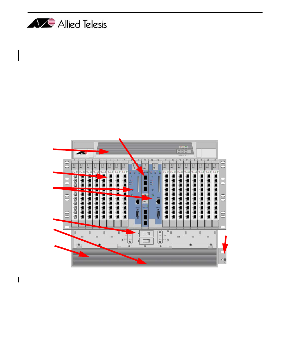
The ATI™ 9700 (see Figure 1-1), is a rack-mounted shelf with a configuration that depends on customer requirements.
C
E
A
B
D
H
RETA
B
F
FIGURE 1-1
Table 1-1 lists the components of the 9700 and how they are configured. Use the letters in this table and refer to
Figure 1-1 to see where the 9700 components are located. Refer to the ATI Component Specification for a
detailed description of all hardware.
ATI 9700 - Installation Guide (Initial Installation of the ATI 9700)
-48/-60A
ATI 9700
G
1-1
Page 8

Unboxing the chassis ATI 9700 Configuration
Note: When the power supply is 60V, the shelf will support only 48V/60V cards, and not 48V cards.
For information on the SMs, CMs. and NMs supported on the 9700 with a 60V power supply
refer to the ATI Component Specification.
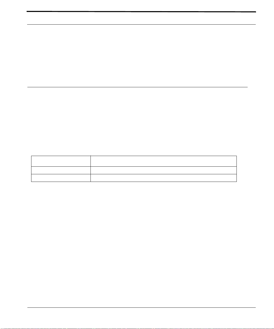
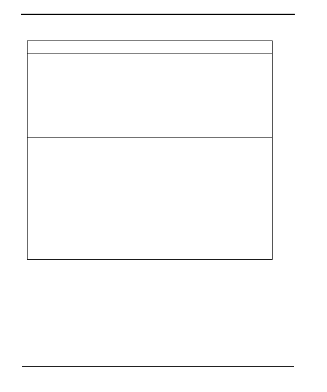
TABLE 1-1
No. Module Slot/Position Configuration Notes
A Service Module
B Control Module
C Network Mod-
D PEM8 Bottom of chassis Power Entry Module. Includes power feeds, signal ground, returns,
Listing of components with slot/position and configuration notes
(SM)
(CM)
ule (NM)
0-7 (left), 14-21
(right), and either 8
or 12.
8, 9 (double) and
12,13 (Duplex
mode)
Slot 10 and Slot 11 At least one is always configured. An unused half-slot requires a
At least one can be configured. Unused slots must be configured
with Filler Plate Fulls (FPF). A mixture of SMs can be configured.
At least one SM must be configured in order to provide service.
At least one card per shelf (occupies two slots).
Duplex mode - Control Module in slots 8/9 and 12/13
Simplex mode - Control Module in slots 8/9 or 12/13. A Service
Module can be inserted into slots 8 or 12 if in Simplex Mode.
Filler Plate Half (FPH).
and A/B circuit breakers.
Note: The PEM8 that supports a 48V/60V power
supply (E002-C) must be used for a 60V power
supply
E F AN8 Top of chassis Fan Module
F ESD Left side ESD wrist strap connection point.
NA FPF Full-height panel
for Service Module
NA FPH Half-height panel
for Network Mod-
ule
G Ground Right side Primary ground connection
H Air Filter Bottom of chassis Air filter
Required when SM slot is not used. Ensures proper airflow and EMI
compliance.
Required when half-slot for NM is not used. Ensures proper airflow
and EMI compliance.
1.2 Unboxing the chassis
To unbox the chassis:
1.
Cut and remove the outer plastic wrap.
2.
Cut and remove the plastic retainer straps.
3.
Remove the top box and place to the side.
1-2
ATI 9700 - Installation Guide (Initial Installation of the ATI 9700)
Page 9
Environment Selecting a Site (Office Installation)
4.
The chassis comes in a lift-off box. Remove the top and lift the box off the chassis. This makes it easier to
access the chassis.
5.
Lift the chassis and place it on a table or workbench.
6.
Carefully cut and remove the chassis from its plastic bag.
Three bags of screws and nuts are included with the chassis and are shipped inside the chassis box. Locate the
three bags and set them aside for later use.
Installation of the system is now ready to begin.
1.3 Selecting a Site (Office Installation)
Before installing the 9700, prepare the site to ensure the product will operate in the correct environment, all materials meet specifications, and all installation tasks can be performed.
1.3.1 Environment
This unit is installed in a controlled office environment that is affected by the existing installed equipment and
the specific requirements of the 9700 shelf. Refer to Table 1-2.
TABLE 1-2
Type Description
Access (for security reasons) To be installed in a restricted access location.
Rear Access None required.
Site Requirements for ATI 9700
ATI 9700 - Installation Guide (Initial Installation of the ATI 9700)
1-3
Page 10
Selecting a Site (Office Installation) Environment
TABLE 1-2
Type Description
Rack configuration Placement: None, but follow local cabling setup (from above, below, etc.)
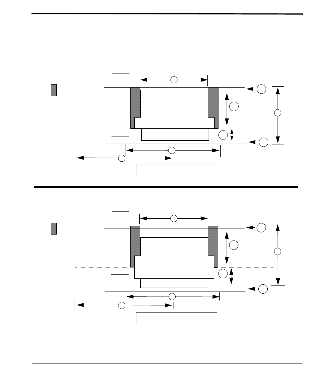
Spacing Refer to Figure 1-2 and its numbers:
Site Requirements for ATI 9700 (Continued)
Care should be taken not to compromise the stability of the rack by the
installation of this equipment.
A maximum of 5 shelves can be mounted into a 7 ft. telecom rack.
Note: Due to weight limitations and the size of bundled cabling, 5 shelves
can physically be installed in a single 7 ft. telecom rack. However, the user
should verify that the floor loading for the rack, with the required number of
units installed, does not exceed the floor loading standard for the region or
country where the 9700(s) is being installed. 9700 installations inside the
U.S. would follow the Bellcore floor loading standard of 114.7 lb. per square
foot. See the ATI Component Specification for the NEBS specification.
1. Mounting Width Aperture: 19.0 in (483 mm) min.
2. Aperture between mounting flanges:
- 17.5 in (444 mm) min. (center-mounted flange)
- 17.5 in (444 mm) min. (front-mounted flange)
3. Total Shelf Depth: mm:
a. Door or cover: .4 in (10 mm) (Front and Back)
b. In front of Reference Plane for equipment (i.e. subracks): 1.6 in (40
mm)
c. Behind Reference Plane: 9.5 in (240 mm)
4. Rack Pitch (Midpoint to Midpoint of each chassis): 20.5 in (520 mm)
Note: Additional width may be required depending on equipment rack up.
For the center mounting option, add 3a and 3b to get the full measurement
for Front and Back.
1-4
ATI 9700 - Installation Guide (Initial Installation of the ATI 9700)
Page 11
Environment Selecting a Site (Office Installation)
Front Mount Option
(Open Rack)
space for external
cable access
(Adjacent Frame)
Reference Plane
Center Mount Option
(Open Rack)
space for external
cable access
Back
Front
4
Back
2
3a
3c
3
3b
3a
1
Top View Looking Down
2
3a
(Adjacent Frame)
Reference Plane
Front
1
4
Top View Looking Down
FIGURE 1-2
ATI 9700 - Installation Guide (Initial Installation of the ATI 9700)
ATI 9700 Space Requirements for Open Rack Environment
3c
3
3b
3a
1-5
Page 12
Selecting a Site (Office Installation) Setup Checklist
1.3.2 Setup Checklist
ATI provides and ships certain parts with each order. Table 1-3 lists the items that are to be provided by ATI.
TABLE 1-3
Item Quantity Description
Machine
screws
ATI Item checklist
4 bags Four bags containing parts are located inside the chassis box:
1. M6 screws
2. 24x1/2 in. screws - These and M6 screws are used to bolt the shelf into the
rack.
Note: The number of screws used depends on how th e shelf
is mounted.
3. Grounding kit (nuts and washers)
4. M3 (8mm length) screws (7)- Used to install the PEM8
channel standoffs
rack panel
adapters
Air filter 1 Air filter unit. Note that the air filter may come mounted in the chassis.
as needed
for center
mount
as needed
for chassis
mounting in
23 in. racks
Optional (Used for chassis center mounting)
Optional (Used for chassis mounting in 23 in. rack)
Table 1-4 lists the items that are to be provided by the customer.
Note: When installing the shelf with the E-0002-C PEM8, ensure that 6 AWG is used for the
installation.
TABLE 1-4
Item Quantity Description
MGMT cable 1 RJ-45, connectorized at one end, CAT 5
Bay Power
Cabling
Alarm cable 3 RJ-45, connectorized at one end, CAT 5
Voltmeter 1 Used to check the voltage at the terminal block
Double crimp
terminal
1-6
Customer Item Checklist
6 AWG, length determined by shelf position and how cabling is routed
as needed Required for ground wiring.
ATI 9700 - Installation Guide (Initial Installation of the ATI 9700)
Page 13

Setup Checklist Selecting a Site (Office Installation)
TABLE 1-4
Item Quantity Description
Crimping
Tool
#1 and #2
Phillips
screwdriver
Ring Terminals
RS232 cable 1 Used to connect local PC/terminal for local interface
Customer Item Checklist (Continued)
1 Used to put ring terminals on power cabling.
1 Used for mounting the chassis
#6 studs for 6 A WG wire
Note: When using an AC-powered terminal or PC, use an
RS232 line isolation unit between the terminal/PC
and the RS232 port. For battery-powered devices,
such as a laptop, this is not required.
cable ties as needed n/a
Rack mount
adapters
materials for
chassis
grounding
MDF and
facilities interface
Small torque
wrench
Recommended for
19 in. or 23
in. rack
mounting
as needed
for chassis
grounding
As required Blocks, cabling, connectors, etc. as required to connect CO facilities to ATI
1 Used to tighten bolts for chassis grounding stud.
Vendor: Newton Instrument Company
Part Number: 2086380945 (9RU Midnight Black adapters)
www.newtoninst.com
1.
6 AWG grounding cable (green with yellow stripe)
2.
two nuts or a lock washer and a nut
3.
double-crimp terminal (PANDUIT PMNF6-4R or equivalent)
equipment. MDF Upgrade Products for interfacing 8 / 16 / 24 port ADSL
modularity are available from ATI.
ATI 9700 - Installation Guide (Initial Installation of the ATI 9700)
1-7
Page 14
Selecting a Site (Office Installation) Setup Checklist
The user has three mounting options available:
•
19” telecom rack front mount
•
19” telecom rack center mount
•
23” telecom rack
The following diagrams illustrate the different mounting options.
1-8
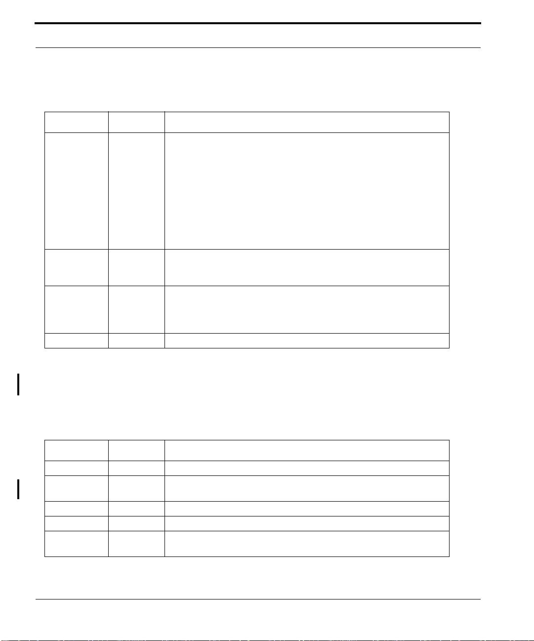
FIGURE 1-3
ATI 9700 - Installation Guide (Initial Installation of the ATI 9700)
Center mounted 9700 with channel standoffs installed (in bold red)
Page 15
Safety ATI 9700 Installation
23 in
RETA
-48/-60A
B
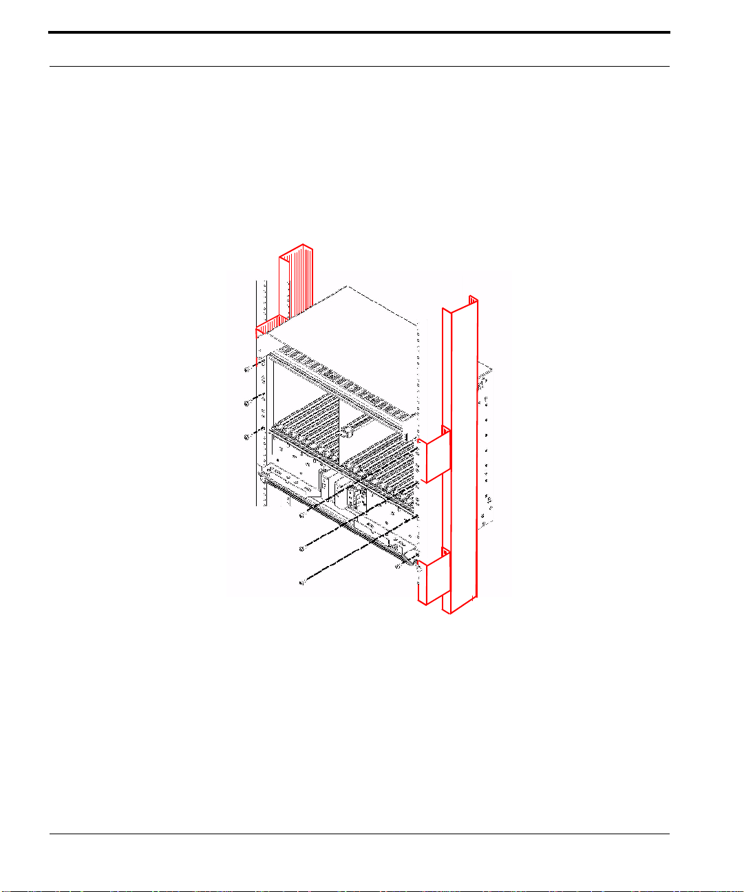
FIGURE 1-4
9700 installed in a 23 inch rack (in bold red)
1.4 ATI 9700 Installation
1.4.1 Safety
Note: Only personnel familiar with local telco practices should install, replace, or service this
equipment.
ATI 9700 - Installation Guide (Initial Installation of the ATI 9700)
1-9
Page 16
A TI 9700 Installati on Safety Precautions While Working wit h Electrici ty
Note: Before starting the installation procedures, the user should read the whole chapter for
important information and safety warnings.
Before installing and cabling the equipment, the user should be aware of standard safety practices and the hazards involved in working with electricity to avoid accidents. See the following
section, Safety Guidelines, for all cautions and warnings to insure that the installation is safe
and free of hazards.
1.4.1.1 Safety Guidelines
Before working on the equipment, the user should be aware of standard safety guidelines and the hazards
involved in working with electricity to avoid accidents. Follow these guidelines and warnings and those located
throughout this installation guide for a safe and hazard-free installation.
Follow these guidelines to insure overall safety:
•
The user should keep all work areas clear and clean during and after installation.
•
The user should keep all tools away from walk areas where personnel could trip over them.
•
The user should not wear loose clothing that could catch on equipment. Secure any loose clothing.
•
The user should wear safety glasses if working under conditions that might be hazardous to eyes.
•
The user should not perform any action that creates an unsafe or hazardous situation for themselves or other
personnel.
1.4.2 Safety Precautions While Working with Electricity
Guidelines when working with electrically powered equipment:
•
Locate the Power Off switch for the system being installed or serviced. In the event of an electrical accident,
the user can quickly turn the power off.
•
Disconnect all power by turning the circuit breakers off before:
•
Installing or removing a chassis
•
Working near the power supply
•
Do not work alone if potential hazards exist.
•
Never assume that power is disconnected from a circuit; always check the circuit.
•
Inspect the work area carefully for possible hazards, such as moist floors, moist or wet ground, ungrounded
power extension cables, frayed power cords, and missing safety grounds.
1.4.3 Setup Precautions
Electrostatic discharge (ESD) can damage equipment when electronic equipment is handled improperly. ESD
damage can produce total or partial failures in electronic equipment. Follow these ESD-prevention procedures
when handling systems cards and modules:
1-10
ATI 9700 - Installation Guide (Initial Installation of the ATI 9700)
Page 17

Setup Precautions Initial chassis configuration
1. Whenever dealing with electrostatic-sensitive equipment, wear a ground or foot strap.
2. Ensure customer power source for the product is off.
1.4.3.1 Antistatic procedures:
1.
Verify that the frame is electrically connected to earth ground.
2.
Wear an ESD-preventive device such as a foot strap or wrist strap, ensuring that it makes good contact
with the user’s skin. If a foot strap is being used, the floor must be ESD conductive.
3.
Connect the clip from the ESD-preventative device to an unpainted surface of the frame, rack or ESD
point on the chassis frame connecting it directly to ground. This ensures that unwanted ESD voltages
safely flow to ground.
4.
W ear the ESD-preventive device correctly to properly guard against ESD damage and shock. If no foot or
wrist strap is available, the user should ground themselves by making contact with an unpainted, metal
part of the chassis.
Ensure customer power source for the product is off.
FCC - The ATI 9700 product complies with FCC requirements for emissions radiation.
Users of the ATI 9700 product are cautioned that any changes or modifications not
expressly approved by the party responsible for FCC compliance could void the user’s
authority to operate the product.
1.5 Initial chassis configuration
Note that the chassis comes ready for the minimum card component configuration. It is filled with filler plates
except for one NM, one CM, and one SM.
1.6 Install the PEM8
Note: Do not attempt to install any system component without observing correct antistatic
procedures. Failure to do so may damage the component or system.
It is more convenient to install the PEM8 while the chassis is positioned on a table, bench or work area laying on
its back with the card slots facing upwards. This makes installing the PEM8 and FAN8 easier.
1.
Take the card from its antistatic container.
2.
Mounting screws are located in the box. Locate and save them for later use.
3.
Find the PEM8 slot. It is located in the bottom of the chassis. Figure 1-5
ATI 9700 - Installation Guide (Initial Installation of the ATI 9700)
1-11
Page 18

Install the PEM8 Setup Precautions
4.
Open the cable management tray to gain access to the PEM8 slot. While holding the PEM8 card upright,
position the bottom of the circuit board into the bottom rail and the top of the circuit board into the top rail in
the PEM8 slot. Slide the PEM8 into the chassis along the rail and down into the chassis. Figure 1-6
5.
Slowly, but firmly, press the PEM8 until it is fully inserted into the backplane and the flange is flush against
the screw holes on the front of the chassis.
6.
Using a small head (#1) phillips screwdriver, take the provided screws and attach the PEM8 to the chassis.
Tighten the screws securely.
FIGURE 1-5
1-12
Power Entry Module 8 slot before PEM8 installation. Note the slot and card rails. Also note
that the cable management tray is open.
FIGURE 1-6
PEM8 installation. Insert the card into the slot and along the rails
ATI 9700 - Installation Guide (Initial Installation of the ATI 9700)
Page 19

Setup Precautions Install the FAN8
1.7 Install the FAN8
1.
Remove the FAN8 from its shipping box.
2.
Take the FAN8 from its antistatic container.
3.
Place it on a table with the front facing the user.
4.
Open the lock-latch on each side of the faceplate. This is performed by curling the thumbs of each hand
behind the lock-latch and pressing the release buttons. The lock-latch arms should swing out from the fan
assembly. Refer to Figure 1-7, Figure 1-8, and Figure 1-9.
PULL FAULT INSERV
COMM ALM OUT ALM IN
FIGURE 1-7
FIGURE 1-8
5.
Make sure both left and right lock-latches are fully open.
6.
Slide the assembly into its slot on the top of the shelf until it is flush with the shelf surface. Figure 1-10
Curl thumbs behind lock-latches and press release buttons (right side detail)
FIGURE 1-9
With thumbs, swing the lock-latches open (right side detail)
FAN8, arrows indicate latch opening
ATI 9700 - Installation Guide (Initial Installation of the ATI 9700)
1-13
Page 20

Install the ATI 9700 Chassis into the Rack Ensure all components for desired configuratio n
FIGURE 1-10
7.
Seat the F AN8 into the shelf by pressing firmly on each side of the as sembly at the lock-latch position (do not
use the lock-latch to seat the card). Close the lock-latches on each side of the faceplate. Figure 1-11, Figure
1-12
FIGURE 1-11
Slide the FAN8 into the chassis
Swing the lock-latches in to close them
FIGURE 1-12
Close the lock-latch
1.8 Install the ATI 9700 Chassis into the Rack
1.8.1 Ensure all components for desired configuration are present
Referring back to Table 1-1 as a guide, ensure that all components used for the installation are present:
1.
Enter into your office records the serial number of the chassis, which will be a S/N label on the rear of the
chassis. (This may be needed if the ATI 9700 requires troubleshooting.)
1-14
ATI 9700 - Installation Guide (Initial Installation of the ATI 9700)
Page 21

Ensure all components for desired configuration are present Install the ATI 9700 Chassis into the Rack
Note: A worksheet to record serial numbers and any o ther informat ion for the ATI 9700 is included at
the end of this document. Refer to the ATI 9700 Inventory Form.
To be safely installed, the ATI 9700 chassis requires two craft persons.
2.
Note the flanges, which are attached so that the shelf is front-mounted.
•
For center-mount, configurations, rack channel standoffs are required. These must be installed onto the
rack prior to installing the chassis.
•
For front-mount or center-mount configurations in 23” racks, rack panel adapters (pair) are required.
These must be installed onto the rack prior to installing the chassis.
3.
Locate the mounting position for the system in the telecom rack.
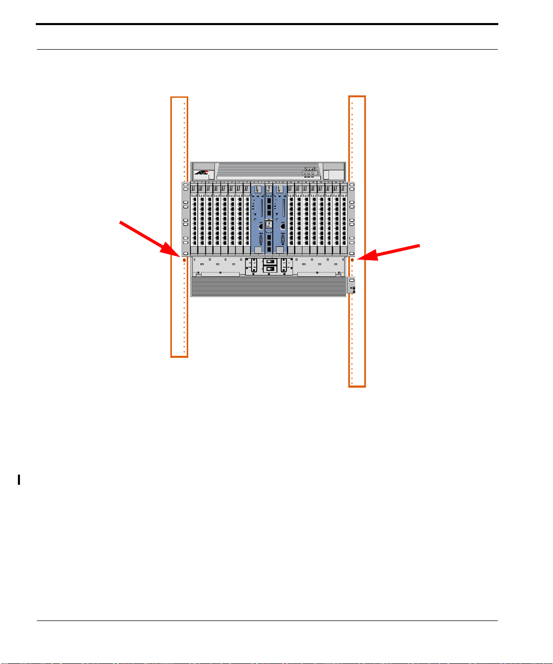
4.
Install a mounting screw (supplied) on each side of the rack. These two screws are temporary and will be used
to hold the weight of the chassis while it is being installed. Do not tighten these two screws. Leave enough
space for the chassis mounting plates to rest on. Screw locations are illustrated in Figure 1-13.
ATI 9700 - Installation Guide (Initial Installation of the ATI 9700)
1-15
Page 22
Install the ATI 9700 Chassis into the Rack Ensure all components for desired configuratio n
RETA
-48/-60A
B
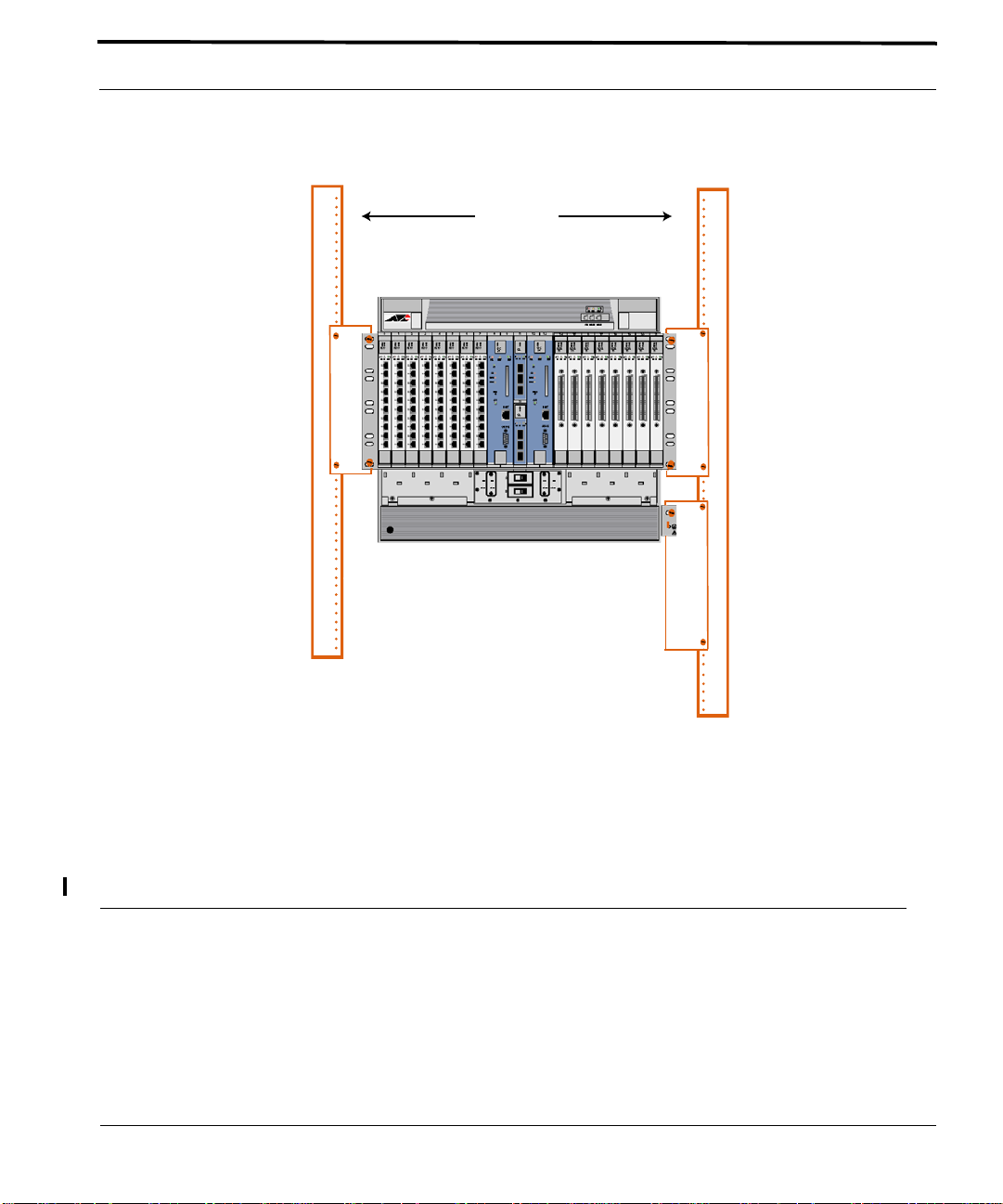
FIGURE 1-13
5.
Lift the chassis and place it into the rack letting the weight rest on the two screws installed in step 3. Align
Install the first two screws as indicated
the chassis mounting holes with the correct holes in the rack. Install the top screws first. (see Figure 1-14)
1-16
ATI 9700 - Installation Guide (Initial Installation of the ATI 9700)
Page 23

Ensure all components for desired configuration are present Install the ATI 9700 Chassis into the Rack
FIGURE 1-14
6.
Install and hand-tighten the remaining mounting screws. Use a minimum of three bolts for each side, with the
Lift the chassis, place it in the rack, align the mounting holes, and install the screws
other two bolts used being one of the middle mounting groups and one at the top. Finally, if not already done,
remove the two screws temporarily installed in step 3. Refer to Figure 1-15.
ATI 9700 - Installation Guide (Initial Installation of the ATI 9700)
1-17
Page 24

Install the ATI 9700 Chassis into the Rack Ensure all components for desired configuratio n
1-18
FIGURE 1-15
ATI 9700 - Installation Guide (Initial Installation of the ATI 9700)
Mounting the ATI 9700 chassis into the rack using the front mount option
Page 25

Overview Connect Grounding
1.9 Connect Grounding
1.9.1 Overview
The primary ground for the ATI 9700 shelf is a grounding stud located on the right side of the chassis mounting
block (it will have the grounding symbol).
The separate protective earthing terminal provided on this product shall be per manently
connected to earth.
Note: There is only one grounding procedure, since with the PEM8 (E002-C), the grounds are
combined.
1.9.2 Grounding Procedure
1.
Using a 6 AWG grounding cable (green with yellow stripe), connect primary ground to the grounding stud
using two nuts or a lock washer and a nut (for two secured points). Connect the wire to the grounding stud
using a double crimp terminal (PANDUIT PMNF6-4R or equivalent). Refer to Figure 1-16.
nut
exploded side view
nut
washer
washer
crimped connector
Grounding stud
FIGURE 1-16
chassis
Grounding stuf
Grounding Stud
Grounding stud exploded view
ATI 9700 - Installation Guide (Initial Installation of the ATI 9700)
1-19
Page 26
Connect Power Power Connection using two feeds
Note: Torque setting for the grounding stud nut is 22.0 in. lb. (2.5 N*m) MAX. When tightening the
outer nut, ensure that the inner nut is held securely.
2.
Since the signal and primary office grounds are combined, installation is complete.
1.10 Connect Power
Before connecting any power (or grounding) cable, ensure the following:
1.
For a 48V source, connect to a reliably grounded 48VDC SELV (
Low Voltage)
not exceed a normal and fault value of 42.4 Vpeak or 60 VDC.)
2.
For a 60V source, connect to a reliably grounded 60VDC SELV (
Low Voltage)
not exceed a normal and fault value of 50 Vpeak or 75 VDC.)
3.
For a 48V installation, the branch circuit overcurrent protection must be rated 30A.
4.
For a 60V installation, the branch circuit overcurrent protection must be rated ???
5.
A readily accessible disconnect device that is suitably approved and rated shall be
incorporated in the field wiring.
6.
The customer-provided power (-48VDC or -60VDC) is off (visibly disconnected) and
the ATI 9700 shelf circuit breakers are OFF).
7.
Use6 AWG copper conductors.
source. (SELV - UL60950 - A circuit designed so that its volt ages do
source. (SELV - UL60950 - A circuit designed so that its volt ages do
Safety Extra
Safety Extra
1.10.1 Power Connection using two feeds
The customer can select to connect the A and B feeds to different customer power sources, so that if one power
source goes down, the shelf can continue to operate.
1.
Remove the plastic covers for the power and grounding terminals.
2.
Connect the power feed and return for A and the power feed and return for B to the separate power supplies.
Use a closed loop termination for securing to the #10 screws of the terminal block on the 9700. An Amp PN
35149 may be used for this. An Amp PN 696202-1 crimping tool will work for securing the recommended
termination part.
1-20
ATI 9700 - Installation Guide (Initial Installation of the ATI 9700)
Page 27

Power Connection using a single feed Connect Power
OFF ON
RETA
RETA
A
-48/-60A
-48A
-48/-60A
RETA
RETA
-48A
OFF
ON
FIGURE 1-17
Connecting A and B to Separate Power Supplies
1.10.2 Power Connection using a single feed
The shelf can operate on only one power feed (A or B).
1.
Remove the plastic covers for the power and grounding terminals.
2.
Using jumper cables, connect the -60V or -48V terminals and the RETA terminals
3.
Connect the A or B -60V and RETA terminals to the power source. Use a closed loop termination for securing to the #10 screws of the terminal block on the 9700. An Amp PN 35149 may be used for this. An Amp PN
696202-1 crimping tool will work for securing the recommended termination part. Refer to Figure 1-18.
ATI 9700 - Installation Guide (Initial Installation of the ATI 9700)
1-21
Page 28

Connect Power Power Connection using a single feed
FIGURE 1-18
Power Connection for a Single Power Source - Need photo with new PEM8 - no ribbon
1-22
ATI 9700 - Installation Guide (Initial Installation of the ATI 9700)
Page 29

Power Connection using a single feed Apply and Check Power
1.11 Apply and Check Power
1.
Ensure the customer power supply is OFF.
2.
Ensure that the ATI 9700 shelf circuit breakers are OFF.
3.
Turn the customer power supply ON. Power is now being applied to the terminal block but not to the 9700
shelf components (PEM8 circuit breakers are OFF).
4.
With the power/grounding plastic covers still removed, using a voltmeter, check for voltage at the following
terminal blocks:
•
For 60V installation:
-60A and RETA
-60B and RETB
•
For 48V installation:
-48A and RETA
-48B and RETB
5.
With the 9700 shelf operating a nominal voltage of -48VDC, the readings for both should be between -40 to -
57.6 VDC. If the voltage is outside this range, check the customer-supplied power.
6.
With the 9700 shelf operating a nominal voltage of -60VDC, the readings for both should be between -36 to 75 VDC. If the voltage is outside this range, check the customer-supplied power.
7.
Put the plastic covers back on.
8.
Apply power to the 9700 PEM8:
1.
First, turn ON circuit breaker A.
2.
The fans should start to operate.
Note: Fan speed is self-regulating and will automatically adjust as necessary.
If the fans do not start, contact ATI Technical Support. See 1.24.
3.
Turn OFF circuit breaker A.
4.
Turn ON circuit breaker B.
5.
The fans should start to operate.
If the fans do not start, contact ATI Technical Support. See 1.24.
6.
Turn OFF circuit breaker B.
9.
Ensure that the 97009700 shelf circuit breakers OFF.
10.
The shelf is now ready for the remainder of the cards to be inserted
ATI 9700 - Installation Guide (Initial Installation of the ATI 9700)
1-23
Page 30

Connect Alarm Cables (Optional) Configurations
1.12 Connect Alarm Cables (Optional)
Note: Connecting the alarm cables at this time is optional. After initial system installation is
complete, the user can return to this section and connect the alarm cables and configure the
system alarms.
Two RJ-45 plugs are used as connecting cables for external alarms. Connect them as follows:
•
one RJ-45 used for alarm indicator input, into the ALM IN port
•
one RJ-45 used for the ALM OUT port as required.
Refer to the ATI User Guide for more information.
1.13 Install the System Cards
The following procedure is recommended for installing ATI system cards.
1.
Remove the card from its antistatic container.
2.
Hold the card securely with the component side to the right (lock-latch and label on the top of the chassis) .
3.
Locate the slot where the card is to be inserted.
4.
Press the release button on the inside of the latches and push the latches out. (Refer to Figure 1-19, Figure
1-20, Figure 1-21)
5.
Insert the card into the specified slot.
6.
While holding the latches/faceplate, slowly but firmly push the card into the slot, avoiding damaging card
electronic components, until the latches begin to engage the locking rail.
7.
Close the latches until they lock into place.
1.14 Control Module(s)
1.14.1 Configurations
The 9700 provides the user with the choice of two configurations, duplex or simplex.
Note: This example is for the CFC24, but it can be applied to any CM supported on the 9700
system.
1.14.1.1 Simplex configuration
To install the CM:
1.
As indicated earlier, the chassis comes with filler plates installed. Remove the filler plates from the two slots
(8 and 9 or 12 and 13) where the CM will be installed.
2.
Take the card from its antistatic container. (Set aside the Special Instructions for Ferrite instructions and
the ferrite for the Ethernet cable. Refer to Section 1.18.3.)
1-24
ATI 9700 - Installation Guide (Initial Installation of the ATI 9700)
Page 31

Duplex configuration Control Module(s)
3.
Follow the card installation procedure detailed in section 1.13.
1.14.2 Duplex configuration
In the duplex configuration, redundancy is provided for the Control Modules. In this configuration the 9700 is
equipped with two CMs. The two CMs operate in conjunction, one operating as the Active system controller,
while the other CM operates as a hot standby mate controller. In this configuration, if a failure occurs on one
Control Module, the mate will take activity and continue operation with no service interruption. The CM can be
installed in either slot 8/9 or 12 /13, however for consistency in th is document, slot 8/9 will be used for in stalling
the first CM (the second CM is installed later in this section).
To install the CMs:
1.
As indicated earlier, the chassis comes with filler plates installed. Remove the filler plates from the two slots
(8 and 9 and 12 and 13) where the CMs will be installed.
2.
T ake the card from its antistatic container. (Set aside the Special Instructions for Ferrite instructions and the
ferrite for the Ethernet cable. Refer to Section 1.18.3.)
3.
Follow the card installation procedure detailed in section 1.13.
ATI 9700 - Installation Guide (Initial Installation of the ATI 9700)
1-25
Page 32

Control Module(s) Duplex configuration
6 7 8 9 11 12 13 14 15
Release
button
TN-300-A
GE3
PULL FAULT INSERV
FIGURE 1-19
Latch in the locked Position
While inserting and removing the CM, be careful not to get fingers pinched between the
card and chassis.
Release
Button
FIGURE 1-20
Detail of the lock-latch in locked position
1-26
ATI 9700 - Installation Guide (Initial Installation of the ATI 9700)
Page 33
Duplex configuration Install the Network Module
Release
Button
FIGURE 1-21
Detail of the lock-latch in open position
1.15 Install the Network Module
Note: This procedure can be applied to any NM supported on the 9700.
The GE3 cards go into Half-Slots 10 and 11. It is recommended that half-slot 10 be filled first (the bottom slot).
1.
Take the card from its antistatic container.
2.
Follow the card installation procedure detailed in section 1.13.
ATI 9700 - Installation Guide (Initial Installation of the ATI 9700)
1-27
Page 34
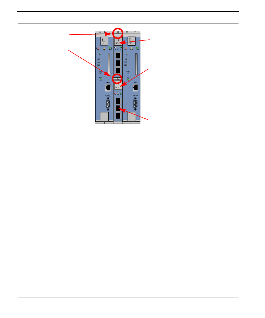
Install the SFP Module Install the Service Modules
GE3 Slot number 11
8 9 11 12 13
GE3 label and lock-latch, slot 11
GE3 Slot number 10
GE3 label and lock-latch, slot 10
TN-300-A
GE3
PULL FAULT INSERV
It is recommended that half-slot 10 be
filled first (the bottom slot)
FIGURE 1-22
Network Module Slot Locations
1.16 Install the SFP Module
The Small Form Factor Pluggable modules, which are inserted in the Network Module cards, can be ordered
from your ATI representative. Refer to the ATI Component Specification for more information.
1.17 Service Modules
Note: This procedure can be applied to any SM supported on the 9700 system.
The ATI 9700 can be equipped with service modules. Following are the installation procedures for service modules.
1.17.1 Install the Service Modules
Service module cards can be placed in any of the following slots: 0-7 (left), and 14-21 (right). It is recommended
that the slots be filled in numerical order 0-7 and then 14-21.
1.
Reposition the filler plates as required to expose the specified SM slot.
2.
Take the card from its antistatic container.
3.
Follow the card installation procedure detailed in section 1.13.
1-28
ATI 9700 - Installation Guide (Initial Installation of the ATI 9700)
Page 35

Install Filler Plates Connect System Cables
1.17.2 Install Filler Plates
While inserting the FPF and FPH, be careful not to get fingers pinched between cards.
Note: Ensure all blank slots are filled with filler plates. The FPF and FPH are needed to keep dust
from entering the chassis and to ensure proper airflow and emissions control. The shelf may
overheat or become damaged if these are not properly installed in every unused slot.
Note: Do not allow the metal plate to touch the components of neighboring cards.
Note: Filler plates may come pre installed with the system.
1.17.3 Installing the FPF
1.
Hold the FPF card securely and slowly but firmly push the card into the slot until the latches begin to engage
the locking rail.
2.
Close the latches until the card locks into place.
1.17.4 Installing the FPH
1.
Hold the FPH card securely and slowly but firmly push the card into the slot until the latch begins to engage
the locking rail
2.
Close the latch until the card locks into place.
The placement of filler plates is dependent upon the configuration of the 9700 system. The following table illustrates the differences between the two configurations.
1.18 Connect System Cables
1.18.1 Service Module
1.18.1.1 SMs with RJ45 connectors
Attach the RJ-45 end of the Ethernet cable to the specified port on the FE10 card.
Note: Each RJ-45 cable connected to the FE10 card should be dressed neatly and tightly. Do
not permit cables to loop. See Figure 1-23.
ATI 9700 - Installation Guide (Initial Installation of the ATI 9700)
1-29
Page 36

Connect System Cables Service Module
FIGURE 1-23
FE10 RJ45 Connector Dressing
1.18.1.2 SMs with Fiber connectors
Attach the optical cables to the ports on the FX10 card.
1.18.1.3 SMs with RJ21 connectors
Attach the connectorized end of the ADSL cable to the ADSL card.
1.
Use the screw and a tie wrap to secure in place.
2.
Split off voice and data service using DC non-blocking splitters
Note: Splitters are not required when utilizing cards with internal splitters.
1-30
ATI 9700 - Installation Guide (Initial Installation of the ATI 9700)
Page 37

Network Module Connect System Cables
Note: Do not over tighten the screw. Hand tighten to secure. Then install the tie wrap, pulling it snug
enough to secure the connector.
FIGURE 1-24
RJ21 cable connector at the SM card
1.18.2 Network Module
1.
Attach the optical cable to the GE3 card.
2.
Attach the other end of the optical cable to the uplink device.
1.18.3 Data Management Cable (MGMT Port on Control Module)
Note: Connect this cable only if the user plans to use the 10/100T Gb MGMT port for the
management interface. Refer to the ATI User Guide.
Referring back to section 1.14.1, the 9700 provides the user with the choice of two configurations, duplex or simplex. For consistency, during initial startup, the system will be configured as simplex and then converted to
duplex mode.
Connect one end of the Ethernet cable to the MGMT port on the Control Module card in slot 8/9 and connect the
other end to a port that connects to the TCP/IP network, as described in the ATI User Guide.
ATI 9700 - Installation Guide (Initial Installation of the ATI 9700)
1-31
Page 38

Connect System Cables Data Management Cable (MGMT Port on Control
SM cabling
dressing
CM
MGMT
port
cable
CM
Console
port
cable
FIGURE 1-25
1
m
e
t
s
y
System 1
S
9700 shelf card connector and wiring detail
NM
port optical
cable
1-32
SM
Cabling
CM
MGMT
Cable
CM
Console
Cable
FIGURE 1-26
Another example of 9700 shelf card connector and wiring detail
ATI 9700 - Installation Guide (Initial Installation of the ATI 9700)
SM
Cabling
NM
Port
Cables
Page 39

Data Management Cable (MGMT Port on Control Module) Configure Local Terminal or PC
1.19 Configure Local Terminal or PC
The RS-232 (CONSOLE) terminal port is used during the initial installation startup to connect the ATI 9700 to a
local management device, which can be:
•
A terminal (VT-100 compatible)
•
A PC with terminal emulation software
The CONSOLE port is a DB9 female socket configured as a DCE, which allows for the direct connection to the
terminal or PC. Refer to ATI Component Specification for a listing of DB9 pin assignments.
The settings for the CONSOLE port are initially configured with the following default values:
When using the CONSOLE port, ensure that the terminal emulation software has FLOW
CONTROL disabled.
TABLE 1-5
Option Default Option Default
ATTENTION BREAK MAXOQLEN 0 (Unrestricted)
CDCONTROL IGNORE MTU 1500
DATABITS 8 NAME ASYN 0
DEF AULTSERVICE FALSE OUTFLOW HARDWARE
DTRCONTROL ON PAGE 22
ECHO ON PARITY NONE
FLOW HARDWARE PROMPT DEFAULT (CMD>)
HISTORY 30 SECURE ON
INFLOW HARDWARE SERVICE NONE
IPADDRESS NONE SPEED 9600
IPXNETWORK NONE STOPBITS 1
LOGIN ON TYPE VT100
Default Asynchronous Port Settings
When using an AC-powered terminal or PC, use an RS232 line isolation unit between
the terminal/pc and the RS232 port. For battery-powered devices (laptop) this is not
required.
Note: Set Flow Control to OFF in order to view the start up sequence from the user terminal.
ATI 9700 - Installation Guide (Initial Installation of the ATI 9700)
1-33
Page 40

Connecting the local terminal and applying power Power and startup sequence
As previously discussed, the ATI 9700 can be configured for two modes of operation, simplex mode (a single
Control Module card in slot 8/9) or duplex mode (two Control Module cards in slots 8/9 and 12/13). During initial startup, the system will be configured as simplex and then be converted to duplex mode.
The following steps provide information and instructions for initial connections of the local terminal and appl ication of power to the system.
1.20 Connecting the local terminal and applying power
1.
Connect the RS-232 cable from the terminal or PC to the ATI 9700 CONSOLE port on the Control Module
in slot 8/9.
Note: The RS-232 is direct connect.
2.
If the device is a PC, bring up the terminal emulation window.
1.20.1 Power and startup sequence
1.
Turn the A and then B circuit breakers on (1).
2.
Observe that the fans should start and airflow should be begin vertically through the unit.
•
Observe the startup sequence on the terminal interface, which should be similar to what is shown below
and end with the prompt
Note: The startup sequence the user observes on the terminal interface may not exactly match the
one illustrated in the figure below. However, it should be free from any error messages.
@@@@@@@@@@@@@@@@@@@@@@@@@@@@@@@@@@@@@@@@@@@@@@@@@@@@@@@@@@@@@@@@@@@@@@@@@@@
Telesyn 24G Central Fabric Controller Boot Loader Version 2.1.g.2
Created on Wed 02/18/2004 at 4:10p
Copyright Allied Telesyn Networks, Inc., 2003
Username
.
VxWorks Version 5.5 for IBM PowerPC 440GP Rev. 2.0
BSP version 1.2/3
Copyright Wind River Systems, Inc., 1984-2002
@@@@@@@@@@@@@@@@@@@@@@@@@@@@@@@@@@@@@@@@@@@@@@@@@@@@@@@@@@@@@@@@@@@@@@@@@@@
FPGA Version 1.4
Starting Telesyn Product Software Loading.
Attaching to Flash File System ... done.
/tffs/ - Volume is OK
Press any key to stop automatic loading of software image...
1
Automatically loading software image...
Loading from boot device 'emac'...
Active CFC or DebugIP enabled: MUX Enabled
Attached TCP/IP interface to emac0.
Attaching network interface lo0... done.
Loading... 22594768
1-34
ATI 9700 - Installation Guide (Initial Installation of the ATI 9700)
Page 41

Power and startup sequence Connecting the local terminal and applying power
Starting at 0x10000...
Creating dosFs device for compact flash...done
Attached TCP/IP interface to emac unit 0
Attaching interface lo0...done
Adding 46530 symbols for standalone.
@@@@@@@@@@@@@@@@@@@@@@@@@@@@@@@@@@@@@@@@@@@@@@@@@@@@@@@@@@@@@@@@@@@@@@@@@@@
,@@@@@@@@@@@@@@@@@@@@,
,@@@@@@@@@@@@@@@@@@@@@@@@@@@@@@@@@@@,
,@@@@ @@@@ @@@@"" ""@@@@@@ @@@@@@ @@@@@,
,@@" @@@",@@@"" ""@@@@@ @@@@@ @@@@@,
,@" ,@@" ,@@" "@@@@@ @@@@ @@@@,
/" /" /" "@@@@ @@@@ @@@@
@@@@@@ /" @""@ @""@ @""@
/ @@ @@@@ @@ @@@@ @@@, @@ @ @@ @
@@ @@ @@ @@ @@ " @@ @ @@@ @ @@@@ @@@@ @@@@
@@ @@@@ @@ @@@@ @@@ @@@ @ @@@ @@@@@@.@@@@.@@@@
@@ @@ @@ @@ , @@ @@ @ @@ @@@@@@.@@@@.@@@@
@@ @@@@ @@@@ @@@@ "@@@ @@ @ @@ @@@@ @@@@ @@@@
Telesyn 24G Central Fabric Controller
Version 4.0.0.BETA.20040715 (Customer Build)
Created on Thu 07/15/2004 at 11:14a
Copyright Allied Telesyn Networks, Inc., 2004
---------------------------------------------Software Version Information
---------------------------------------------Build name : Telesyn 24G Central Fabric Controller
Build type : Lab-Only Build
Revision : 4.0.0.BETA.20040715
Built on : Thu 07/15/2004 at 11:14a
Built by : ccadmin
Environment: ccbuild_R4.0_nightly_integration
Baseline : Integration Latest
Target : cfc24
Options :
---------------------------------------------Boot ROM Version Information
---------------------------------------------Boot ROM : Telesyn 24G Central Fabric Controller Boot Loader
Revision : 2.1.g.2
Built on : Wed 02/18/2004 at 4:10p
Built by : mbuilder
Environment: mbuilder_R2.1_integration
Baseline : Integration Latest
BuildTarget: bootcfc24
----------------------------------------------
ATI 9700 - Installation Guide (Initial Installation of the ATI 9700)
1-35
Page 42

Connecting the local terminal and applying power Power and startup sequence
VxWorks Version 5.5 for IBM PowerPC 440GP Rev. 2.0
BSP version 1.2/3
Copyright Wind River Systems, Inc., 1984-2002
Memory Size: 255 MB
WDB Comm Type: WDB_COMM_END, State: Ready
@@@@@@@@@@@@@@@@@@@@@@@@@@@@@@@@@@@@@@@@@@@@@@@@@@@@@@@@@@@@@@@@@@@@@@@@@@@
********************
* WARNING: Debug IP mode is currently enabled.
********************
* WARNING: Standard Telesyn boot procedure has been disabled.
********************
System Time is 2004-07-19 09:55:41.005
System initializing...
/tffs/ - Volume is OK
Initialization completed successfully
User Access Verification
Username:
3.
Check for fault indicators by comparing the actual message with what is shown in Step 2
•
On the CM in slot 8/9, the LEDs should be as follows (for the active CM)
1-36
ATI 9700 - Installation Guide (Initial Installation of the ATI 9700)
Page 43

Power and startup sequence Connecting the local terminal and applying power
89
TN-400-A
CFC
24
PULL FAUL T INSRV
ACT
CRIT
MAJOR
MINOR
SWACT
ACO'LT
FIGURE 1-27
•
ACT = ON
•
PULL = OFF
•
FAULT = OFF
•
INSRV = ON
•
Alarm LEDs - CRIT, MAJOR, MINOR = OFF
4.
Depending on what is observed in Step 3, perform the following:
•
If there are no faults, go to Step 10
•
If there are faults and this is the first time power has been applied to the 9700, go to Step 5
•
If there are faults and this is the second time power has been applied to the 9700, go to Step 9
5.
A Major alarm will be raised if any of the NM ports are enabled, but not connected to an uplink. If there are
9700 CM LED
unused ports, log into the system and disable them using the DISABLE PORT command. In the following
example, ports 10.1 and 10.2 are unused and have no uplink; therefore, they are generating a Major alarm.
The alarms are cleared by disabling the ports.
Log into the system, input a user ID of officer and a password of officer
ATI 9700 - Installation Guide (Initial Installation of the ATI 9700)
1-37
Page 44

Connecting the local terminal and applying power Power and startup sequence
officer SEC> SHOW ALARMS ALL
------------------------------------------------------------------------------ Slot 10, Port 01 Loss Of Signal Major
Slot 10, Port 01 Loss Of Link Major
Slot 10, Port 01 Loss Of Sync Major
Slot 10, Port 02 Loss Of Signal Major
Slot 10, Port 02 Loss Of Link Major
Slot 10, Port 02 Loss Of Sync Major
-------------------------------------------------------------------------------
officer SEC> disable port 10.1,10.2
Service may be affected, are you sure (Y/N)? y
Info (039512): Operation Successful (GE3 Slot 10 Port 01)
Info (039512): Operation Successful (GE3 Slot 10 Port 02)
Once the alarms are cleared and there are no other alarms, go to step 10. If alarms are still present, go to step
6.
6.
Turn system power off
7.
Remove and replace the Control Module card for slot 8/9, following the guidelines in 1.10
8.
Start the power sequence again (return to Step 1 and repeat Steps 1 - 4)
9.
Since the Control Module in slot 8/9 has been replaced once and there are still faults, contact your ATI Technical Support. See 1.24.
10.
Stop Installation Procedure
11.
Log into the system, input a user ID of officer and a password of officer
12.
Execute the PURGE DATABASE command. The system will erase the initial configuration database, reboot,
and recover with factory defaults. This provides a baseline for startup system configuration.
The system is initially in the auto-provisioning mode by default. This means that hardware is discovered in a slot
where there is no prior provisioning and the cards and ports are automatically provisioned. This discovery occurs
when:
•
The card is inserted into a slot
•
The card is already inserted and the following occurs:
1.
The Control Module powers up
2.
The Control Module reboots
3.
The system mode is changed from manual to autoprov.
13.
Determine the next step by whether the system will be in simplex or duplex configuration,
•
If simplex, go to section 1.21
•
If duplex, go to Step 14
14.
Install the second Control Module card in slot 12/13, following the procedure in section 1.13
1-38
ATI 9700 - Installation Guide (Initial Installation of the ATI 9700)
Page 45

Power and startup sequence Log into the system
Since the system is initially in the auto-provisioning mode by default. The Control Module is discovered in th e
slot and is provisioned, in this case as the inactive Control Module (INACTCFC).
15.
Check for fault indicators on the inactive Control Module in slot 12/13:
The LEDs should be as follows:
•
ACT = OFF
•
PULL = OFF
•
FAULT = OFF
•
INSRV = ON
•
Alarm LEDs = OFF
16.
Depending on what is observed in Step 4, perform the following:
•
If there are no faults, go to section 1.21 to check for any other alarms.
•
If there are faults on the inactive Control Module card, troubleshoot the faulty Control Module card by
referring to the 9700 User Guide.
1.21 Log into the system
1.
Check the management logs for any problems by inputting the following.
Note: Command responses are representative examples only. Initial system startup responses
should be relatively free of error logs.
SHOW LOG SEVERITY=CRITICAL
SHOW LOG SEVERITY=MAJOR
SHOW LOG SEVERITY=MINOR
SHOW ALARMS ALL
The MAC card is located internally behind Service Module slots 2/3 of the chassis. When the system is first powered up, if the MAC card is defective, the following message and alarm is produced:
•
A SYS009 log is generated with text “Cannot Read MAC Address”
•
A major alarm is set against the shelf with the text “Cannot Read MAC Address”
If the above condition exists, the user can display system MAC information using the SHOW SYSTEM command. An example follows. Note that this is only a partial listing of the SHOW SYSTEM command:
officer SEC>> SHOW SYSTEM
--- System Information --------------------------------------------------------
System Date................... 2004-07-19 10:12:46
System Uptime................. 0 days, 00 hours, 17 minutes, 01 seconds
Shelf Serial Number........... 0056174030700130 A1
Software Version.............. 4.0.0.BETA.20040715
ATI 9700 - Installation Guide (Initial Installation of the ATI 9700)
1-39
Page 46

Log into the system Check software load
Software Options.............. Customer Build
Software Created.............. Thu 07/15/2004 at 11:14a
SDRAM (free/total)............ 180786 KB / 262144 KB
Flash (free/total)............ 100476 KB / 130560 KB
Booted from................... preferred
Provisioning Mode............. MANUAL
Contact....................... <none>
Location...................... <none>
Name.......................... <none>
Services...................... Layer 2 - Datalink/Subnetwork
MGMT MAC address.............. Cannot Read MAC Address
Number of MACs on card........ 4
Description................... Telesyn 9700 Multiservice Access Platform
Hostname...................... <none>
MGMT IP Address............... 172.16.66.62
MGMT Subnet Mask.............. 255.255.255.0
MGMT Gateway.................. 172.16.66.1
MGMT Domainname............... <none>
MGMT DNS...................... <none>
If any logs are produced, or if an alarm has a status other than INFO, contact ATI Technical Support and review
the output. See 1.24.
1.21.1 Check software load
Check the software loads on the system cards using the SHOW CARD command. An example follows:
officer SEC>> SHOW CARD ACTCFC SOFTWARE
-------------------------------------------------------------------------------
Fault................................. No Faults
Card.................................. 8,9
Card Type............................. CFC24
Activity Status....................... ACTIVE
Admin State........................... UP
Operational State..................... UP
Status................................ Online
Profile Name.......................... AutoProv
Profile Has Been Modified............. No
Diagnostic Result..................... Not Run
Diagnostics Scheduled................. No
Temporary SW Load..................... None
Preferred SW Load..................... cfc24_4.0.0.BETA.20040708.tar
Alternate SW Load..................... None
Running Load..................... ..... cf c24 _4. 0.0 .BETA. 20 040 708 .tar
Load File............................. vxWorks
Build Name............................ Telesyn 24G Central Fabric Controller
Build Type............................ Customer Build
Revision.............................. 4.0.0.BETA.20040715
1-40
ATI 9700 - Installation Guide (Initial Installation of the ATI 9700)
Page 47

Check management interfaces Uninstall the system
Built on.............................. Thu 07/15/2004 at 11:14a
Built by.............................. ccadmin
Environment........................... ccbuild_R4.0_Customer_Build
Baseline.............................. Integration Latest
Boot ROM Build Name................... Telesyn 24G Central Fabric Controller
Boot Loader
Boot ROM Revision..................... 2.1.g.2
1.21.1.1 ATI 7700
Although control modules and service modules are shipped with release files already present in FLASH memory,
the release file should be compared with the latest software release files that are available from ATI or if this is a
replacement card, the current system loads. See section 1.24 for contact information.
Once a software release file is downloaded onto a network server, copy it to the Control Module FLASH file system, load it into FLASH memory, make it the active load, and ensure that when the Control Module reboots this
latest load is always used. If this is a replacement card, make sure that the current system load is loaded into the
card. Also ensure the service module loads are obtained from the control module.
Details on the steps to do this are in section, File Manage ment and Soft ware Re lease Upgr ade of the ATI User
Guide.
1.21.1.2 ATI 9700
The CFC24 in the 9700 comes equipped with optional Compact FLASH (CFLASH). Compact Flash (CFLASH)
is a removable memory card that will insert into the faceplate of CFC24 Control Module. This extra memory can
be used to store release load files, databases, and captured log files. Compact FLASH is a small portable card that
the user inserts into the CFC24 similar to FLASH on a digital camera or other device. See Section 8 of the ATI
User Guide for more information on CFLASH.
Refer to the ATI Component Specification for information on 9700 hardware and software compatibilities.
1.21.2 Check management interfaces
The ATI 9700 is now connected to a local terminal over an RS232 cable and can be queried. Refer to the ATI
User Guide which shows how to query the initial ATI 9700 status.
The ATI User Guide can then be used to configure the management interfaces.
For more information on system hardware refer to the ATI Component Specification.
1.22 Uninstall the system
To uninstall the system, reverse the installation procedures detailed above.
ATI 9700 - Installation Guide (Initial Installation of the ATI 9700)
1-41
Page 48

Replacing Existing PEM8 with E002-C Check management interfaces
1.23 Replacing Existing PEM8 with E002-C
It may be necessary to replace the PEM8 on an existing 48V shelf. The replacement PEM8 is the E002-C. The
following procedure should be used to ensure the new PEM8 is installed properly.
Note: Follow standard safety and anti-static guidelines.
1.
Working with network engineers, ensure that data traffic is handled appropriately during this procedure,
since the shelf must be powered down and so will not be passing traffic.
2.
Shut down the power supply to the shelf, following local practice. (Examples would be removing power supply fuses or setting circuit breakers to OFF.)
3.
Turn the breakers on the existing Power Supply to the OFF position. (Since breakers are vertical in the old
PEM8, push them down.)
4.
Using a voltmeter, ensure there is no voltage between the -48 or RTN leads.
5.
Using wire snips, cut all the tie wraps associated with the power cabling going to the PEM8.
6.
Remove the PEM8 guard shield from both the A and B sides.
7.
Remove the A and B power cables from the PEM8.
8.
Remove all seven retaining screws of the PEM8, and set these aside.
9.
Ensure the cable management tray is open, in preparation for the next step.
10.
Remove the PEM8. (Follow local practice on what to do with this PEM8, such as returning it to Allied Telesis.)
11.
Remove the guard rails located in the PEM8 slot:
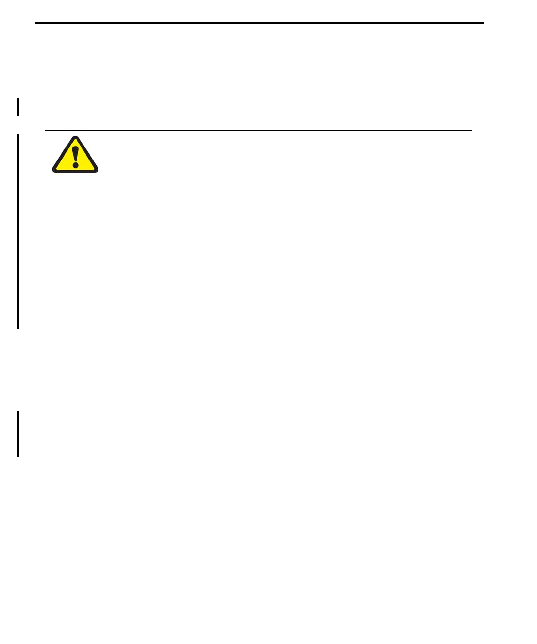
1.
Remove the top guide rail. Refer to Figure 1-28.
1-42
FIGURE 1-28
Removing Top Guide Rail
ATI 9700 - Installation Guide (Initial Installation of the ATI 9700)
Page 49

Check management interfaces ATI Contact Information
2.
Remove the bottom guide rail. (Note that it is easier to remove the bottom rail by loosening the retain ing
guide bracket.) Refer to the following figure.
FIGURE 1-29
12.
If installed in slot 10, remove the GE3 card.
13.
Insert the new PEM8 (TN-E002-C). Since guide rails are not used, guide the Power Supply into the PEM8
Removing Bottom Guide Rail
slot until the PEM8 is seated properly and the retaining screw holes line up.
14.
Install the seven retaining screws into the new PEM8.
15.
Reconnect the A and B power cables to the PEM8.
16.
Reinsert the GE3 into slot 10 if it was removed.
17.
Reinstall the guard shields.
18.
Turn the Power Supply breakers to the ON position. (The breakers are horizontal in the E002-C PEM8.)
19.
Restart the power supply to the shelf, following local practice. (Examples would be inserting power supply
fuses or setting circuit breakers back to ON.
20.
Using a voltmeter, ensure there is the proper voltage between the 48V and RTN leads. (Refer to 1.10.)
21.
Redress the power cables.
22.
Ensure the shelf powers up correctly. Refer to 1.20.
1.24 ATI Contact Information
If assistance or information is required in the installation of this equipment, contact ATI Technical Support or
your ATI Representative.
ATI 9700 - Installation Guide (Initial Installation of the ATI 9700)
1-43
Page 50

ATI Contact Information Check management interfaces
1-44
ATI 9700 - Installation Guide (Initial Installation of the ATI 9700)
Page 51

2. Appendix
2.1 Glossary of Terms
TABLE 2-1
Acronym Meaning
ADSL Service module. ADSL8S, ADSL16, and ADSL24. Annex-A or Annex-B with 8, 16, or 24 ports.
FE10 Service module. Fast Ethernet (10/100) service with 10 ports
FX10 Service module. Optical Fast Ethernet service with 10 ports
CFC24 Control Module. Controller with 24G Bandwidth
CM Control Module.
FAN8 Fan Module
FPF Filler Panel Full. Occupies a full slot
FPH Filler Panel Half. Occupies a half slot
GE3 Network Module. Gigabit Ethernet service 3 port
MAC Media Access Controller. Number that uniquely identifies a network component
NM Network Module
PEM8 Power Entry Module
POTS24 Service module. POTS 24 port.
SHDSL16 Symmetric Highspeed Digital Subscriber Line. 16 port.
SM Service Module.
Glossary of Terms
2.2 Telesyn x700 Inventory Form
You can use the following form to record registration information about the Telesyn x700 and keep with your
office records.
Note: You may also identify the product with CLI commands. Refer to the Telesyn User Guide.
ATI 9700 - Installation Guide (Appendix)
2-1
Page 52

Telesyn x700 Inventory Form
TABLE 2-2
No. Location Serial Number Notes
1
2
3
4
5
6
7
8
9
10
11
12
13
14
15
16
17
18
19
20
Registration Information for the Telesyn x700
2-2
ATI 9700 - Installation Guide (Appendix)
 Loading...