

Page 1
Specifications
Item Specification
Dimensions (H x W x L)
Operating Temperature 0° C to 40° C
Storage Temperature -20° C to 80° C
Relative Humidity <85% non-condensing
Supply Voltage +3.15 V - +3.45 V
Bit Rate 100 Mb/s - 2700 Mb/s
Optical Output Power +1 dBm - +3 dBm
Receiver sensitivity (BER
<10^-10 for OC rates, BER
<10^-12 for GbE)
Receiver Optical Overload -7 dBm
29.21 x 43.85 x 243.22 mm
(1.15 x 1.71 x 9.57 in.)
-28 dBm (OC-48)
-31 dBm (GbE)
-33 dBm (OC-12)
-35 dBm (OC-3)
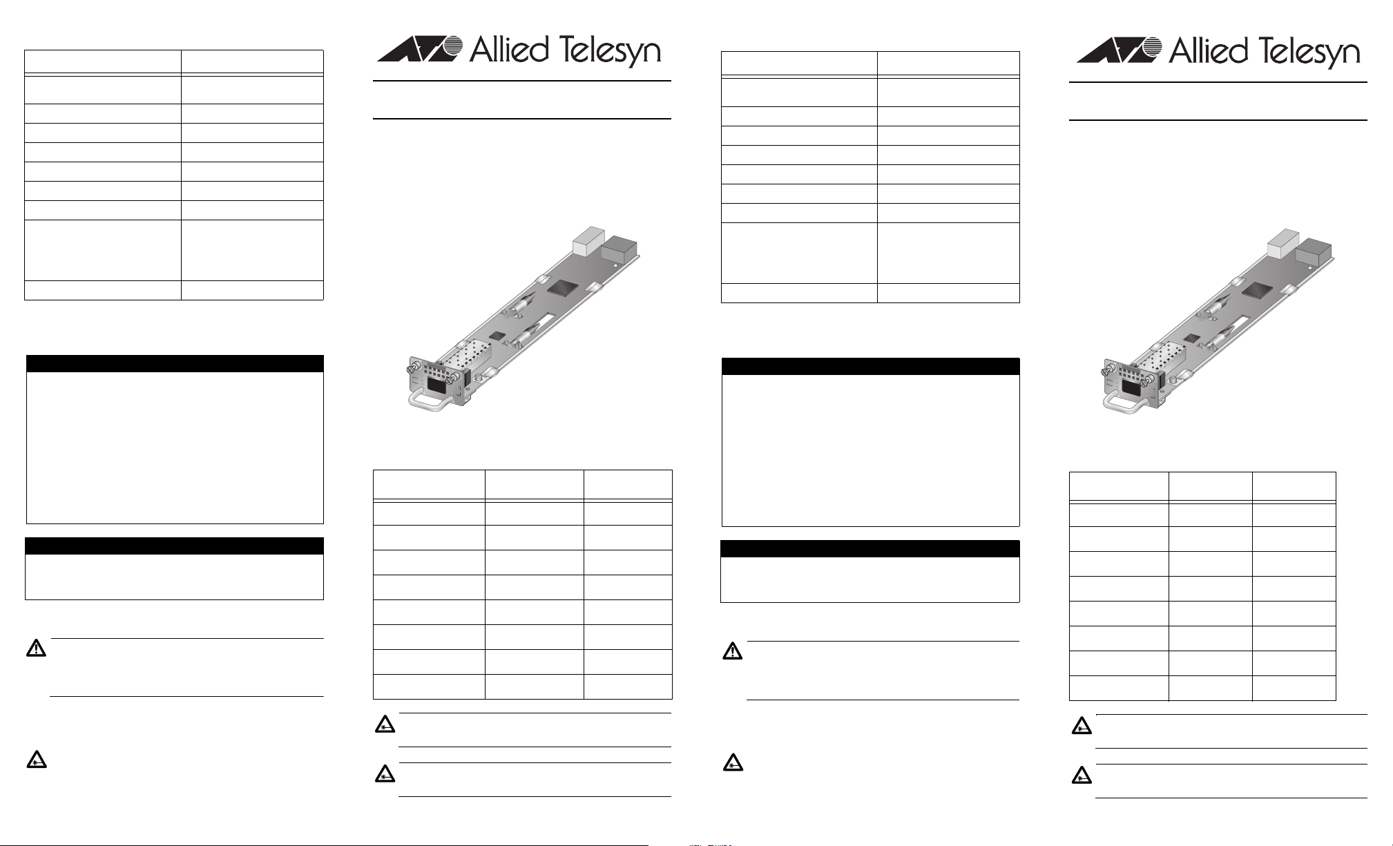
AT-LX3811/x Multi-Service Line Card
Installation Guide
Overview
An AT-LX3811/x Multi-Service Line Card is designed for use
in an AT-LX3800U Multi-Service Transport System. Each
line card contains one optical SFP transceiver port. The line
cards are hot swappable into and out of the system. Each
line card can only be used in its dedicated slot.
Specifications
Item Specification
Dimensions (H x W x L)
Operating Temperature 0° C to 40° C
Storage Temperature -20° C to 80° C
Relative Humidity <85% non-condensing
Supply Voltage +3.15 V - +3.45 V
Bit Rate 100 Mb/s - 2700 Mb/s
Optical Output Power +1 dBm - +3 dBm
Receiver sensitivity (BER
<10^-10 for OC rates, BER
<10^-12 for GbE)
Receiver Optical Overload -7 dBm
29.21 x 43.85 x 243.22 mm
(1.15 x 1.71 x 9.57 in.)
-28 dBm (OC-48)
-31 dBm (GbE)
-33 dBm (OC-12)
-35 dBm (OC-3)
AT-LX3811/x Multi-Service Line Card
Installation Guide
Overview
An AT-LX3811/x Multi-Serivce Line Card is designed for use
in an AT-LX3800U Multi-Service Transport System. Each
line card contains one optical SFP transceiver port. The line
cards are hot swappable into and out of the system. Each
line card can only be used in its dedicated slot.
Electrical Safety and Emission Statement
This product meets the following standards.
U.S. Federal Communications Commission
Radiated Energy
Note: This equipment has been tested and found to comply with the
limits for a Class A digital device pursuant to Part 15 of FCC Rules.
These limits are designed to provide reasonable protection against
harmful interference when the equipment is operated in a
commercial environment. This equipment generates, uses, and can
radiate radio frequency energy and, if not installed and used in
accordance with this instruction manual, may cause harmful
interference to radio communications. Operation of this equipment in
a residential area is likely to cause harmful interference in which
case the user will be required to correct the interference at his own
expense.
Note: Modifications or changes not expressly approved of by the
manufacturer or the FCC, can void your right to operate this
equipment.
Industry Canada
This Class A digital apparatus meets all requirements of the
Canadian Interference-Causing Equipment Regulations.
Cet appareil numérique de la classe A respecte toutes les exigences
du Règlement sur le matériel brouilleur du Canada.
RFI Emissions EN 55022 Class A
Warning
In a domestic environment this product may cause
radio interference in which case the user may be
required to take adequate measures.
Immunity EN 55024
Electrical Safety UL 1950 (
Laser Safety EN 60825 (Class 1)
Copyright © 2004 Allied Telesyn, Inc. All rights reserved. No part of this publication
may be reproduced without prior written permission from Allied Telesyn, Inc.
www.alliedtelesyn.com
), EN 60950 (TUV)
CULUS
A
T-LX
3
811/8
R
D
Y
T
T
R
X
IB
R
X
S
Y
N
C
T
X
L
IN
E
S
F
P
R
X
The line card models, their corresponding wavelengths, and
their slot position in the AT-LX3800U system are listed in the
following table.
Model Wavelength Slot Number
AT-LX3811/1 1470 1
AT-LX3811/2 1490 2
AT-LX3811/3 1510 3
AT-LX3811/4 1530 4
AT-LX3811/5 1550 5
AT-LX3811/6 1570 6
AT-LX3811/7 1590 7
AT-LX3811/8 1610 8
Laser
Class 1 laser product.
Laser
Do not stare into the laser beam.
PN 613-50550-00 Rev. A
Electrical Safety and Emission Statement
This product meets the following standards.
U.S. Federal Communications Commission
Radiated Energy
Note: This equipment has been tested and found to comply with the
limits for a Class A digital device pursuant to Part 15 of FCC Rules.
These limits are designed to provide reasonable protection against
harmful interference when the equipment is operated in a
commercial environment. This equipment generates, uses, and can
radiate radio frequency energy and, if not installed and used in
accordance with this instruction manual, may cause harmful
interference to radio communications. Operation of this equipment in
a residential area is likely to cause harmful interference in which
case the user will be required to correct the interference at his own
expense.
Note: Modifications or changes not expressly approved of by the
manufacturer or the FCC, can void your right to operate this
equipment.
Industry Canada
This Class A digital apparatus meets all requirements of the
Canadian Interference-Causing Equipment Regulations.
Cet appareil numérique de la classe A respecte toutes les exigences
du Règlement sur le matériel brouilleur du Canada.
RFI Emissions EN 55022 Class A
Warning
In a domestic environment this product may cause
radio interference in which case the user may be
required to take adequate measures.
Immunity EN 55024
Electrical Safety UL 1950 (
Laser Safety EN 60825 (Class 1)
Copyright © 2004 Allied Telesyn, Inc. All rights reserved. No part of this
publication may be reproduced without prior written permission from Allied
Telesyn, Inc. www.alliedtelesyn.com
), EN 60950 (TUV)
CULUS
A
T-LX
3811/8
R
D
Y
T
T
R
X
IB
R
X
S
Y
N
C
T
X
L
IN
E
S
F
P
R
X
The line card models, their corresponding wavelengths, and
their slot position in the AT-LX3800U system are listed in
the following table.
Model Wavelength Slot Number
AT-LX3811/1 1470 1
AT-LX3811/2 1490 2
AT-LX3811/3 1510 3
AT-LX3811/4 1530 4
AT-LX3811/5 1550 5
AT-LX3811/6 1570 6
AT-LX3811/7 1590 7
AT-LX3811/8 1610 8
Laser
Class 1 laser product. Do not stare into the laser beam.
Laser
Do not stare into the laser beam.
PN 613-50550-00 Rev. A
Page 2
Related Documents
RDY
TX
RX
TRIB
SYNC
TX
RX
LINE
2
3
4
5
6
SFP
SYNC
TX
RX
LINE
RDY
TX
RX
TRIB
AT-LX3811/3
SFP
SYNC
TX
RX
LINE
RDY
TX
RX
TRIB
AT-LX3811/4
TRIB
RD
T
R
TRIB
X3811/2
SFP
SYNC
TX
RX
LINE
AT-LX3811/8
S
FP
S
Y
N
C
T
X
R
X
L
IN
E
R
D
Y
T
X
R
X
T
R
IB
SFP
SYNC
TX
RX
LINE
RDY
TX
RX
TRIB
AT-LX3811/6
2
3
4
5
6
SFP
SYNC
TX
RX
LINE
RDY
TX
RX
TRIB
AT-LX3811/3
SFP
SYNC
TX
RX
LINE
RDY
TX
RX
TRIB
AT-LX3811/4
TRIB
RD
T
R
TRIB
X3811/2
SFP
SYNC
TX
RX
LINE
SFP
SYNC
TX
RX
LINE
RDY
TX
RX
TRIB
AT-LX3811/6
SFP
SYNC
TX
RX
LINE
RDY
TX
RX
TRIB
AT-LX3811/5
RDY
TX
RX
TRIB
SYNC
TX
RX
LINE
2
3
4
5
6
SFP
SYNC
TX
RX
LINE
RDY
TX
RX
TRIB
AT-LX3811/3
SFP
SYNC
TX
RX
LINE
RDY
TX
RX
TRIB
AT-LX3811/4
TRIB
RD
T
R
TRIB
X3811/2
SFP
SYNC
TX
RX
LINE
AT-LX3811/8
S
FP
S
Y
N
C
T
X
R
X
L
IN
E
R
D
Y
T
X
R
X
T
R
IB
SFP
SYNC
TX
RX
LINE
RDY
TX
RX
TRIB
AT-LX3811/6
2
3
4
5
6
SFP
SYNC
TX
RX
LINE
RDY
TX
RX
TRIB
AT-LX3811/3
SFP
SYNC
TX
RX
LINE
RDY
TX
RX
TRIB
AT-LX3811/4
TRIB
RD
T
R
TRIB
X3811/2
SFP
SYNC
TX
RX
LINE
SFP
SYNC
TX
RX
LINE
RDY
TX
RX
TRIB
AT-LX3811/6
SFP
SYNC
TX
RX
LINE
RDY
TX
RX
TRIB
AT-LX3811/5
For details on the features and functions of your Allied
Telesyn AT-LX3800U Multi-Service Transport System, refer
to the following documents on our web site,
www.alliedtelesyn.com:
• AT-LX3800U Multi-Service Transport System
Installation and Maintenance Guide
(part number 613-50549-00)
• AT-S65 Management Software User’s Guide
(part number 613-50604-00)
Verifying Package Contents
Make sure that the correct components are included in your
package:
• AT-LX3811/x Multi-Service Line Card
• This installation guide
• Warranty card
If any item is missing or damaged, contact your Allied
Telesyn sales representative for assistance.
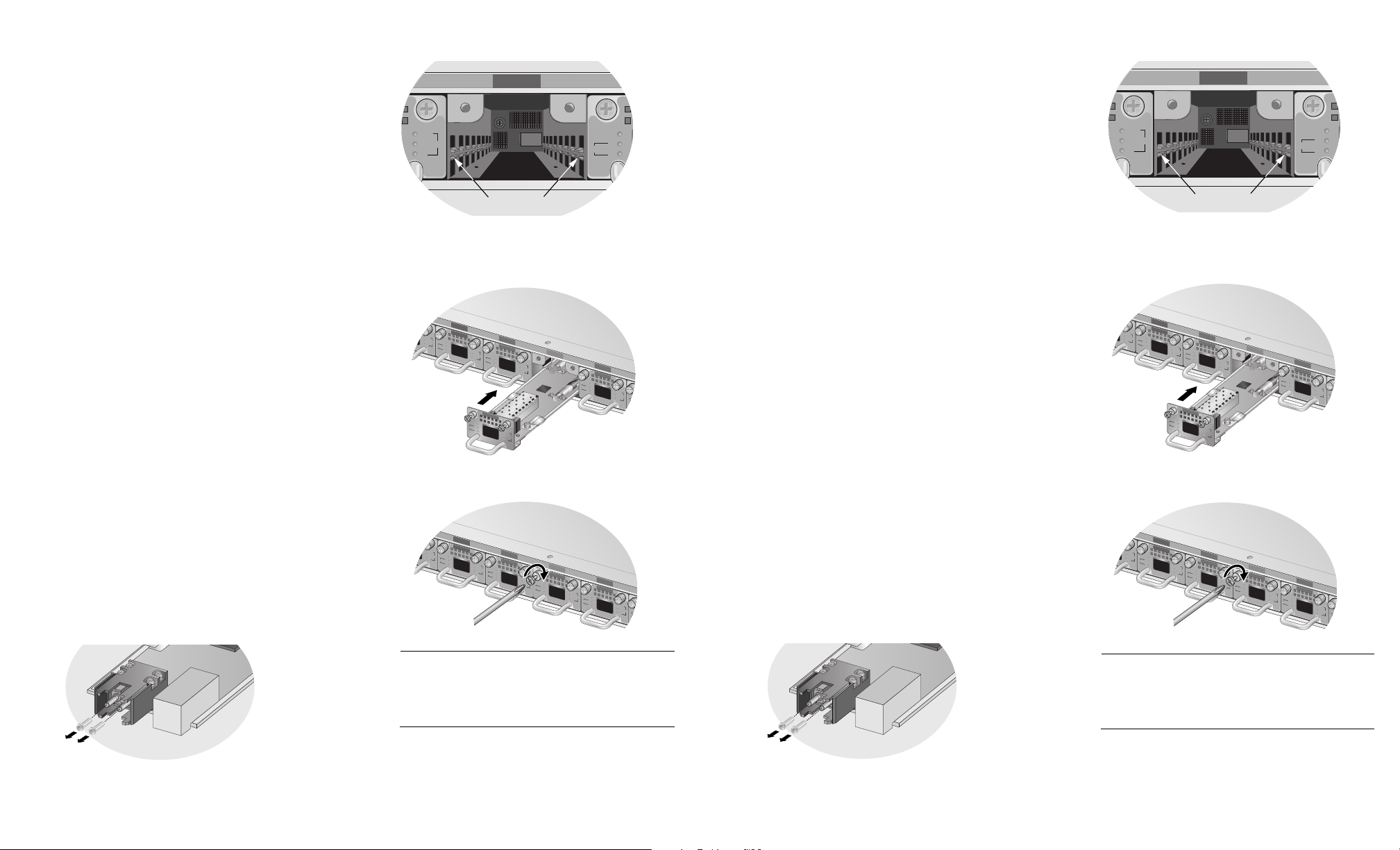
5. Locate the left and right alignment guides in the slot.
138
Alignment Guides
6. Align the back edge of the line card with the left and
right alignment guides.
7. Slide the card into the slot that corresponds to the line
card number, until the faceplate is flush with the front.
Related Documents
For details on the features and functions of your Allied
Telesyn AT-LX3800U Multi-Service Transport System, refer
to the following documents on our web site,
www.alliedtelesyn.com:
• AT-LX3800U Multi-Service Transport System
Installation and Maintenance Guide
(part number 613-50549-00)
• AT-S65 Management Software User’s Guide
(part number 613-50604-00)
Verifying Package Contents
Make sure that the correct components are included in your
package:
• AT-LX3811/x Multi-Service Line Card
• This installation guide
• Warranty card
If any item is missing or damaged, contact your Allied
Telesyn sales representative for assistance.
5. Locate the left and right alignment guides in the slot.
138
Alignment Guides
6. Align the back edge of the line card with the left and
right alignment guides.
7. Slide the card into the slot that corresponds to the line
card number, until the faceplate is flush with the front.
Installing the Line Card
To install an AT-LX3811/x Line Card, perform the following
procedure:
1. Remove the AT-LX3811/x line card from its shipping
package and store the package in a safe place. You
must use the original package if you need to return the
unit to Allied Telesyn.
2. Select the slot in the AT-LX3800U chassis that
corresponds to the number of the line card you want to
install.
3. Remove any AT-LX3801 Blank Slot Cover from the
slot.
Keep the blank slot cover in a safe area in case you
remove the line card. The blank slot cover protects the
fiber optic connectors on the backplane from becoming
dirty, and helps maintain proper air flow through the
chassis.
4. Remove the dust caps from the fiber optic connectors
at the back of the card and save for future use.
173
139
8. Use a Phillips head screwdriver to tighten the captive
screws on the line card.
140
Note
Always tighten the captive screws to secure the line
card to the chassis. This helps ensure that the fiber
optic connectors at the back of the line card are
securely connected to the backplane.
9. Repeat this procedure to install additional line cards.
For information about the line card LEDs, installing SFPs in
the line card, and connecting fiber optic cables, refer to the
AT-LX3800U Multi-Service Transport System Installation
and Maintenance Guide.
 Loading...