

Page 1
Page 2

WARRANTY REGISTRATION AND POLICY
Buhler Manufacturing products are warranted for a period of twelve (12) months from
original date of purchase, by original purchaser, to be free from defects in material and
workmanship under correct, normal agricultural use and proper applications.
Buhler Manufacturing's obligations under this warranty shall be limited to the repair or
exchange, at Buhler Manufacturing’s option, of any Buhler Manufacturing product or
part which proves to be defective as provided. Buhler Manufacturing reserves the right
to either inspect the product at the buyer’s location or have it returned to the factory for
inspection.
The above warranty does not extend to goods damaged or subject to accident, abuse
or misuse after shipment from Buhler Manufacturing’s factory, nor to goods altered or
repaired by anyone other than an authorized Buhler Manufacturing representative.
Buhler Manu^cturing makes no Express Warranties other than those which are
specifically described. Any description of goods, including any references and
specifications in catalogues, circulars and other written material published is for the sole
purpose of identifying goods and shall conform to such descriptions. Any sample or
model is for illustrative purposes only and does not create an Express Warranty that the
goods conform to sample or model shown.
The purchaser is solely responsible for determini^ig suitability of goods sold. This
warranty is expressly in lieu of all other warranties expressed or implied. Buhler
Manufacturing will in no event be liable for any incidental or consequential damages
whatsoever, nor for any sum in excess of the price received for the goods for which
liability is claimed.
WARRANTY CLAIMS:
Warranty requests must be prepared on Buhier Manufacturing Warranty Claim Forms
with all requested information properly completed. Warranty Claims must be submitted
within a thirty (30) day period from date of failure repair.
WARRANTY LABOR:
Any labor subject to warranty must be authorized by Buhler Manufacturing. The labor
rate for replacing defective parts, where applicable, will be credited at a rate determined
by the Company, Buhler Manufacturing.__________________________________________________
IMPORTANT FACTS;
Buckets and Bucket Tines Carry No Warranty
Bent Spears Carry No Warranty
Snowblower Fan Shafts Carry No Warranty
Mower Blades Carry No Warranty
Portable Auger Parts Have Two (2) Year Warranty
Loader Parts Have Two (2) Year Warranty
PRINTED IN CANADA
Page 3
Page 4
Page 5
Page 6
Page 7
Page 8
Page 9
Page 10

Page 11

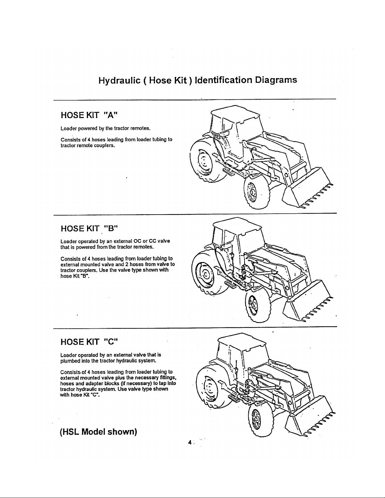
General Instructions and Information
As with any piece of equipment, the care with which your loader is operated
and maintained will greatly affect it's life and the safety of the people using it.
1. Keep all pivots well lubricated for longer bushing life. Inspect every 500
hours of operation for wear.
2. Periodically check all bolts for tightness. If any bolt is damaged, replace it
with a bolt of equivalent grade or strength.
3. Follow the recommendations of the tractor manufacturer in regards to the
quantity of oil used.
4. Check oil level frequently to ensure the system is full.
5. When making an oil check, be sure lift cylinders are retracted.
6. Before operating the loader, particularly if the loader is left standing for
any length of time, check the hydraulic system and oil level.
7. When installing hydraulics, follow the circuit carefully. See hydraulic
hook-up section and make sure the hoses dip not contact any hot
manifolds or sharp edges on tractor. After assembly, raise the loader slowly
and check to make sure that the hoses do not bind in all positions.
A
The pressure of the relief and open centre valves is set at the factory. Do
not tamper with the setting. Serious injury to the operator or damage to the
loader or tractor hydraulics may occur. Warranty will be void if the loader is
operated above recommended pressure.
CAUTION
8. When servicing any hydraulic components, care must be taken to prevent
any foreign matter from entering the system.
9. Do not neglect oil leaks. Leaks affect loader operation, are dangerous and
can result in personal injury or damage to the hydraulic system.
10. Never leave the cylinder shafts exposed when loader is not in use.
11. Worn or damaged components should be replaced as soon as possible with
only the manufacturer's recommended component or equivalent.
Page 12

Page 13

Page 14

Page 15

Page 16

Page 17

Page 18

Page 19

Trouble Shooting
PROBLEM
Loader slow and/or will not dump.
Loader chatters or vibrates when
raising and lowering.
Excessive movement at pivots
Pump noisy
Oil leaks.
Insufficient lift capacity
Slow leakdown.
Excessive wear on bottom oil bucket
and wear pads.
Hydraulic cylinders inoperative.
Pump operating continually on closed Tractor control valve relief stuck
center tractor hydraulic system. open.
Loader lift and bucket tilt controls do
not work according to decal.
Valve noisy and/or hot
Tractor loads/pump squeals
POSSIBLE CAUSE
Quick couplers leaking.
Hydraulic oil too heavy.
Oil filter plugged.
Hydraulic pump worn.
Oil line restricted or leaking.
Control valve does not shift properly.
Air in hydraulic system.
Cylinder leaks internally.
Faulty valve.
Air leak in pump inlet line.
Air in hydraulic system.
Oil level too low.
Worn bushings and/or pins.
Inlet line restricted or leaking.
Oil level too low.
Pump worn or damaged.
Damaged fittings or hoses.
Loose connections. \
Worn or damaged O-ring wiper
seal in cylinder rod end.
Worn or damaged O-rings in valve.
Improper hydraulic pump operation. Repair or replace pump.
Load is greater than boom lift capacity. Check loader specifications.
Internal boom cylinder leakage. Replace any worn parts and install
Improper hydraulic valve operation. Repair or replace valve.
Worn control valve.
Worn cylinder piston seals.
Float position not used while operating Use float position provided on valve,
loader.
Hose from.control valve improperly
connected.
Hydraulic control valve set too low.
Hoses improperly connected.
Open center control valve on closed
center tractor.
Closed center control valve on open
center tractor.
17
REMEDY
Check connections and compatibility or
replace.
Change or replace filter.
Clean or replace filter.
Repair or replace pump.
Check all hoses and tubes for leaks,
damage or restrictions. Replace damaged
or restricted hoses or tube lines.
Inspect, clean, repair or replace valve.
Cycle lift cylinders and bucket cylinders
several times to free system of air.
Replace seals.
Repair or replace valve.
Check, tighten or replace inlet line.
Cycle lift cylinders and bucket cylinders.
Add oil as required.
Replace bushings and/or pins.
Check for air leaks, restrictions or collapsed
hose. Tighten or replace hose. Clean
filter if necessary.
Add oil as required.
Repair or replace pump.
Replace damaged parts.
Tighten fittings.
Install a seal repair kit.
Install an O-ring repair kit.
a seal repair kit.
Have authorized dealer replace seals.
Have authorized dealer replace seals.
Refer to plumbing diagrams.
See your tractor manual for proper
adjustment or Loader dealer for loader
valve. (3000 PSI is maximum pressure
relief setting recommended.)
Adjust valve in accordance with manual.
Refer to plumbing diagrams
and correct hose connections.
Replace relief valve with closed center plug
and plug the power beyond adapter on valve.
Install open center plug on optional valye.
Replace closed center plug with relief and
install short plug in place of power beyond
adapter.
Page 20

Page 21

395, S395 )
Sub Frame Parts Table
Item
1
2
1
2
3
4
5
6
7
8
9
10
11
12
13
14
15
16
17
18
19
20
21
22
23
24
25
26
Part No.
31611
31610
31622
31623
113253
112747
112746
112748
114531
114537
112642
113281
113746
812717
812026
812882
84289
84127
812939
81967
81723
112730
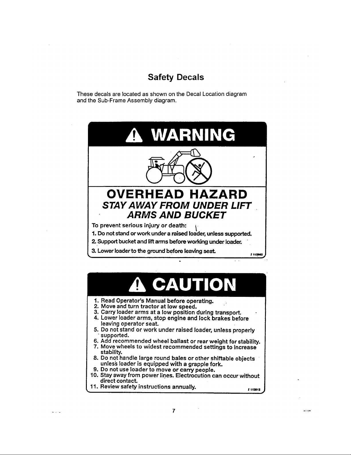
112812
113500
112615
112982
112983
113474
Description
395 Sub Frame Weldment Left
395 Sub Frame Weldment Right
395 S Sub Frame Weldment Left
395 S sub Frame Weldment Right
Hook Weldment
Plate Clamp
Speer Block
Shim
Cross Member Weldment
Tube Cross Member
Shaft Pivot 1.75 Dia. x 5.50 Long
Bolt Retainer Weldment
Loader Lift Lock Weldment
Grommet 0.375 ID x 1.00 OD
Bolt Hex 0.313nc x 1.00 gr5 pi ’
Bolt Car. 0.625nc x 2.50 gr5 pi
Bolt Hex 0.625nc x 3.00 gr5 pi
Bolt Car. 0.625nc x 3.50 gr5 pi
Bolt Hex 0.875nc x 10.00 gr8 pi
Nut Lock (Nylon) 0.625nc grB pi
Washer Lock 0.875 pi
Washer Boot
*Decal - General Caution
*Decal- 395x1.40
‘Decal-Sxl.40
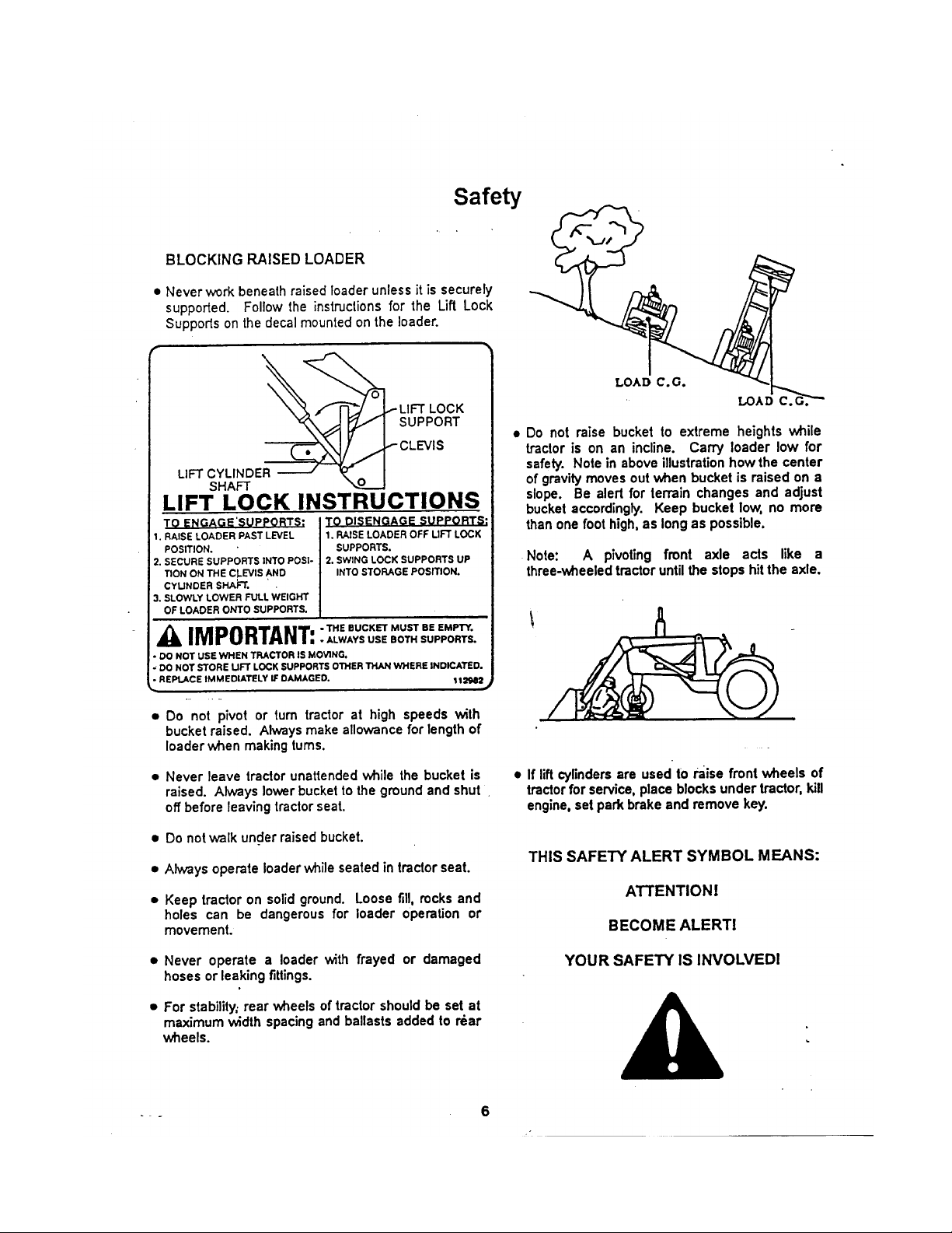
‘Decal - Lift Lock Instruction
‘Decal - Warning Overhead Hazard
‘Decal - Cross Member Caution
395
1
1
2
2
4
2
1
1
2
2
2
2
2
4
8
2
2
14
2
2
2
2
2
2
2
S395
1
1
2
2
4
2
1
1
2
2
2
2
2
4
8
2
2
14
2
2
2
2
2
2
2
2
*Part of decal replacement kit XI296
19
Page 22

Page 23

39S, S395 i|
Main Frame Parts Tab1e^|
Item Part No. Description
395 Main Frame Weldment
395S Main Frame Weldment
Attachment Bracket
Stand Weldment
Strap Stand
Wrench Mounting
Pin 0.625 Dia. Stand
Hair Pin Clip #9 Western Wire
Cotter Pin 5/32 x 1.0
Leveling Rod (48.0")
Pin 1.25 Dia. X 6.75 Long
Pin 1.25 Dia. X 5.00 Long
Bushing 1.25 ID X 1.50 d)D X 1.375 Long
Tube Co\«r
2.0 Dia. X 20.75 Bucket Cylinder
2.0 Dia. X 20.75 Lift Cylinder
Bolt Hex 0.375nc x 2.50 gr5 pi
Bolt Hex 0.625nc x 3.50 gr5 pi
Nut Hex 0.375nc gr2 pi
Nut Lock (nylon) 0.375nc grB pi
Nut Lock (nylon) 0.625nc grB pi
10
11
12
13
14
15
16
17
18
19
1
1
2
3
4
5
6
7
8
9
20
31620
31621
114354
114536
24329
110907
12779
84162
114524
112954
112955
113766
24242
24493
24495
81581
81669
81592
81344
81967
21 81570 Washer Flat Std 0.375 hs pi
22 112614 *Decal - Allied X 1.75
23 52281-000 *Bright Orange Scotchcal #72368
395 S395
1
1
2
2
1
2
2
2
1
2
2 2
1
1
8
4
8
1
2
2
12
4
4
16
6
4
2
8.5ft
1
1
8
4
8
1
2
2
12
4
4
16
6
4
2
7.5ft
"Part of decal replacement kit XI296
21
CDR
Page 24

Page 25

395, S395 LOADER
Plumbing Parts Table |
Item Part No.
1
24493
2
24495
3
812973
4
811754
5
812947
6
114526
7
114527
8
113031
9
114528
10
114529
11
112837
12
812128
13
811414
14
812069
15
11362
16
81592
17
81344
Description
2.0 Dia. X 20.75 Cyl. Assy Bucket
2.0 Dia. X 20.75 Cyl. Assy Lift
3/8x12 Hose 3/4 MORB x 3/4 SWFJIC
3/8x18 Hose 3/4 MORB x 3/4 SWFJIC
3/8 X 22 Hose 3/4 SWFJIC x 3/4 SWFJIC
Tubing - Lift Cyl. Bottom Raise
Tubing - Lift Cyl. Top Drop.
Tubing - Lift Cyl. Top Drop Common (23.0")
Tubing - Bucket Cyl. Bottom Rollback
Tubing - Bucket Cyl. Top Dump
Tubing - Bucket Cyl. Cross Tube
Elbow 90 3/4 MJIC x 3/4 MJIC
Elbow 90 3/4 MORB x 3/4 MJIC
Tee 3/4 MJIC
Clip Pipe Std.
Nut Hex 0.375nc gr2 pi
Nut Lock (Nylon) 0.375nc grB pi
Qty.
2
2
4
2
2
1
1
2
1
1
2
4
2
4
11
4
9
23
Page 26

Page 27

Page 28

 Loading...