

Page 1
SG Series Boilers – Installation and Service Manual
SG-135
SG-180
SG-225
SG-270
SG-315
SG-360
SG-400
SG-450
SG-495
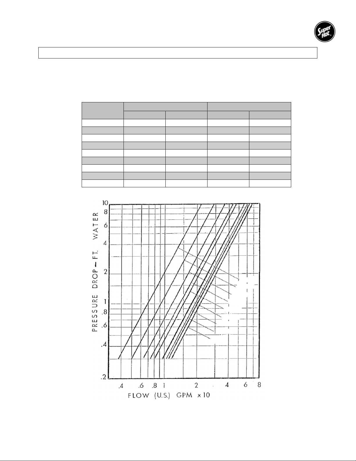
Boiler Water Flow Data
NOTE: The boiler should be properly sized for its heating application and maintain an adequate water
flow rate during operation. Significantly over sizing the boiler or decreasing boiler water flow
rate will cause excessive stage cycling and may result in premature failure of components.
Typical Water Flow versus Pressure Drop across Boiler
Model
Number
U.S. GPM P.D. FT. U.S. GPM P.D. FT.
SG-135 11.5 2.8 7.7 1.2
SG-180 15.3 2.8 10.2 1.2
SG-225 19.1 2.8 12.8 1.2
SG-270 23.0 2.8 15.3 1.2
SG-315 26.5 3.2 17.7 1.3
SG-360 30.3 3.2 20.2 1.4
SG-400 33.7 3.3 22.5 1.4
SG-450 37.9 3.8 25.3 1.6
SG-495 41.7 4.0 27.8 1.8
20F ΔT 30F ΔT
SG Heat Exchanger Pressure Drop Graph
5
Page 2

SG Series Boilers – Installation and Service Manual
If you do not follow these instructions exactly, a fire or explosion may result causing property
ABOUT OUR MANUALS
Your Super Hot boiler has been provided with two manuals:
User's Information Manual - This manual is intended for the owner or user of the boiler and provides
information on routine operation and maintenance, and emergency shutdown.
Installation and Service Manual - This manual must only be used by a qualified heating installer,
service technician or gas supplier. Installation or service by anyone unqualified to do so may result
in severe personal injury, death or substantial property damage.
Both manuals should be kept in the envelope provided and affixed adjacent to the boiler so that they are
readily available for future reference.
Lighting Instructions Section 1
1.1 SAFETY INSTRUCTIONS
WARNING
damage, personal injury or loss of life.
A. BEFORE LIGHTING smell all around the
boiler area for gas. Be sure to smell next to
the floor because some gas is heavier than air
and will settle on the floor.
WHAT TO DO IF YOU SMELL GAS
Do not try to light any appliance.
Do not touch any electrical switch; do not
use any phone in your building.
Immediately call your gas supplier from a
neighbor's phone. Follow the gas
supplier's instructions.
If you cannot reach your gas supplier, call
the fire department.
B. Use only your hand to push in or turn the gas
control knob. Never use tools. If the knob will
not push in or turn by hand, don't try to repair it,
call a qualified service technician. Force or
attempted repair may result in a fire or
explosion.
C. Do not use this boiler if any part has been under
water. Immediately call a qualified service
technician to inspect the appliance and to
replace any part of the control system and any
gas control which has been under water.
1.2 LIGHTING INSTRUCTIONS
Determine the ignition system that applies from the list below and go to the applicable lighting instruction
section.
Intermittent electronic ignition with combination gas valve (Section 1.3)
Intermittent electronic ignition with non-combination gas valve (Section 1.4)
Note: A combination gas valve combines the operating and safety shut-off into one valve body.
A non-combination gas valve system utilizes separate valve bodies for operating and safety shut-off.
6
Page 3
SG Series Boilers – Installation and Service Manual
1.3 LIGHTING INSTRUCTIONS FOR INTERMITTENT ELECTRONIC IGNITION
WITH COMBINATION GAS VALVE.
1. This boiler is equipped with an ignition device
which automatically lights the pilot. Do not try
to light the pilot by hand. Ensure gas supply to
the boiler is turned on.
2. STOP! Read the safety instructions in
Section 1.1.
3. Set the room thermostat to lowest setting.
4. Turn off all electrical power to the appliance.
5. Remove control access panel if necessary.
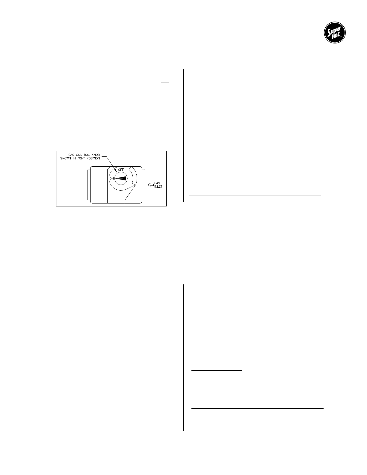
6. Push in gas control knob slightly and turn
clockwise to "OFF".
NOTE: On some gas valves the knob cannot be
turned to "OFF" or “ON” position unless knob is
pushed in slightly. Do not force.
7. Wait five (5) minutes to clear out any gas. Then
smell for gas, including near the floor. If you
smell gas, STOP! Follow "A" in the safety
instructions in Section 1.1. If you don't smell
gas, go to the next step.
8. Turn gas control knob counterclockwise
to "ON".
9. Replace control access panel if necessary.
10. Turn on all electrical power to the boiler.
11. Set room thermostat to desired setting.
12. If the appliance will not operate, follow the
instructions "To Turn Off Gas To Boiler" in
Section 1.6 and call your service technician or
gas supplier.
To turn off gas to boiler or emergency shut-off
Follow Section 1.5.
1.4 LIGHTING INSTRUCTIONS FOR INTERMITTENT ELECTRONIC IGNITION
WITH NON-COMBINATION GAS VALVE.
This boiler is equipped with an ignition device, which automatically lights the pilot. Do not try to light the
pilot by hand. Before turning on the electrical power switch, be sure all gas supply lines are purged of air
and power supply to control is the correct voltage.
If the pilot or main burners are not lit or the control system is locked-out due to flame failure, close the main
and pilot gas shut-off valves and call your service technician or gas supplier. If you smell gas, STOP! Follow
“A” in the safety instructions in Section 1.1.
Check Control Operation
1. STOP! Read the safety instructions in Section
1.1.
2. For 100% shut off check, close main and pilot
manual gas shut off valves, turn off all electric
power to the boiler and wait for five minutes to
clear out any gas.
3. Then smell for gas, including near the floor. If
you smell gas, STOP! Follow safety
instructions in Section 1.1. If you don’t smell
gas, go to the next step.
4. Set the thermostat above room temperature
and turn on all electric power to the boiler to
energize the electronic ignition and pilot valve.
After a few seconds, control system should
“lockout” and all functions are off.
5. To take the control system out of “lockout”
either press the reset button or interrupt power
to the boiler, depending on the boiler
controller. Some controllers will retry ignition
automatically after 5 minutes lockout.
Start System
1. Turn on the main and pilot manual gas shutoff valves.
2. Set thermostat above room temperature and
turn on all electrical power to the boiler.
3. Once the pilot flame is proven, the controller
opens the main burner gas valves. The pilot
flame will ignite the gas as it exits the main
burner ports.
4. Set thermostat to the desired setting to put
system back in service.
Relight Operation
Five minutes complete shut off period is required
before attempting to relight the boiler. To relight
the boiler, follow the Start System procedure
(above).
To turn off gas to boiler or emergency shut-off
Follow Section 1.5
7
Page 4
SG Series Boilers – Installation and Service Manual
Should the boiler overheat, or the gas supply fail to shut off, do not turn off or disconnect the
Operation of this control may delay the burner operation while the residual heat is circulated out
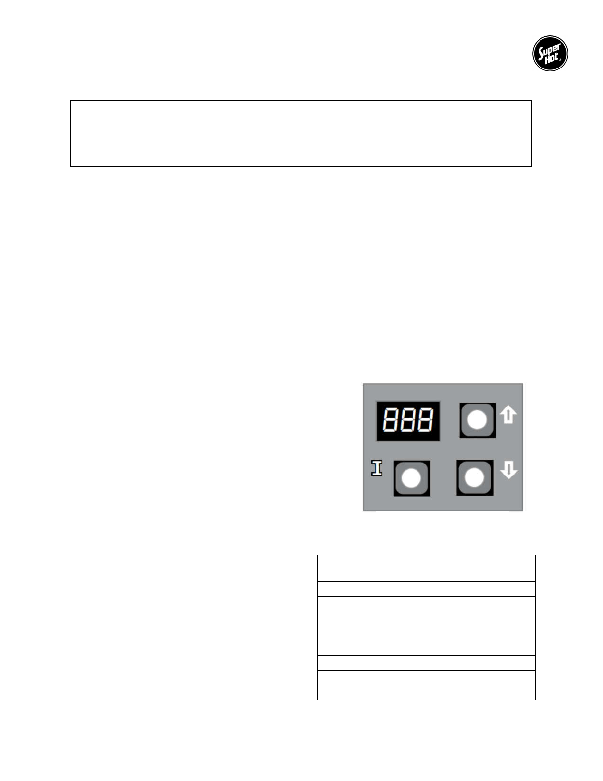
Figure 1 Control Display
Table 1 - Run Mode Parameters
1.5 TO TURN OFF GAS TO THE BOILER OR EMERGENCY SHUT-OFF
WARNING
electrical supply to the circulating pump. Instead, shut off the gas supply at a location external
to the boiler.
1. Set the thermostat to the lowest setting.
2. Turn all electrical power to the boiler off.
3. Remove control access panel on the boiler if necessary.
4. For combination valve: Push in gas control knob slightly and turn clockwise to "OFF". Do not force
it.
For non-combination valve: Close the main and pilot manual gas shut off valves. The valve is "OFF"
when handle is perpendicular to the direction of gas flow.
5. Replace control access panel if necessary.
1.6 CONTROLLER PROGRAMMING AND SERVICE CODES (SG-135 to SG-270)
2012 NRCan and DOE Compliance and Operation
of the boiler.
The integrated boiler control module provides ignition
sequence, flame monitoring and safety shutoff for intermittent
pilot spark ignition. It also provides limit rated water
temperature control for with two separate sensors in one
casing (3-wire).
The control is located on the front panel inside the boiler.
The control display, along with Up ▲, Down ▼, and “I” keys
may be used to view boiler operating status and program
parameters (Figure 1).
1.6.1 RUN MODE
In the RUN mode, status items and parameters are
viewable.
To read settings, press and release the “I” key to
find the parameter of interest. Each setting will
alternately flash between the relevant display code
listed in the Table 1 and its corresponding value.
For example, press and release “I” key until “”
setpoint is displayed, it will then flash a three-digit
number, i.e., 220, followed by ˚F (or ˚C). This
indicates that the boiler water temperature of 220 ˚F
is set. Other operating parameters display the
settings in a similar fashion.
Text Description Display
STA
BT
SP
HL
HDF
FLA
RUN
CYC
ERR
Status (see status numbers)
Boiler temperature
Operating setpoint
High limit setpoint
Differential set-point
Flame current
Run time hours
Boiler cycles
Error (see error numbers)
8
Page 5

SG Series Boilers – Installation and Service Manual
Table 2 - Installer Mode Options
1.6.2 INSTALLER MODE
To enter the adjustment mode:
1. Press with Up ▲, Down ▼, and “I” keys (see Figure 1) simultaneously for three seconds.
2. Press and release the “I” key until the parameter (listed in the Table 2) requiring adjustment is
displayed.
3. Press with Up ▲ or Down ▼ key until the parameter has reached the desired value.
4. After 60 seconds without any key inputs, the control will automatically return to the RUN Mode.
3-Digit 7-Segment Display
1st Screen 2nd Screen (setting value) 3rd Screen
<high limit>
<high limit differential>
<pump overrun time> Sec 60 sec 0 to 120 seconds Pump post-purge time
<ODR maximal temp.>
<ODR minimal temp.>
<minimal water temp.>
<minimal boiler temp.>
<maximal delay> Min 2 1 to 10 minutes
On or OFF N/A N/A Reset lockout
˚F or ˚C
˚F or ˚C 180 ˚F 130 to 220 ˚F
˚F or ˚C 15 ˚F 10 to 30 ˚F
˚F or ˚C 55 ˚F 40 to 70 ˚F
˚F or ˚C 0 ˚F -40 to 40 ˚F
˚F or ˚C 140 ˚F 130 to 150 ˚F
˚F or ˚C 140 ˚F
Default Range
OFF,
120 to 160 ˚F
˚F ˚F or ˚C
Description
Adjust high limit setting
Adjust high limit
differential
Maximal outdoor
temperature
Minimal outdoor
temperature
Minimal boiler
temperature
Thermal purging
minimal temperature
(parameter is available
only if outdoor
temperature is invalid)
Maximal thermal purge
time (parameter is
available only if outdoor
temperature is invalid)
Select degrees ˚F or ˚C
mode
9
Page 6
SG Series Boilers – Installation and Service Manual
PRESS and HOLD
1.6.3 OPERATING CHECKOUT
After adjusting parameters, put the boiler into operation and observe operation through at least one
complete cycle to make sure that the controller operates properly. See controller troubleshooting section
to assist in determining boiler operation.
The sensor should fit snugly and should touch the bottom of the well for best temperature response. The
sensor is held inside the well using the well clip.
1.6.4 THERMAL PURGE
The intent of thermal purge is to ensure usable residual heat in the boiler is circulated until it is sufficiently
depleted from the system before the burner is allowed to fire. To that end, on a call for heat, the burner
remains off while the circulator runs until the boiler temperature drops to the thermal purge temperature
limit or the time delay is exceeded. Both of these parameters are adjustable. When the boiler temperature
falls below the thermal purge temperature limit or the time delay expires, the burner is allowed to fire.
In addition to the thermal purge temperature and thermal purge time delay parameters, two other conditions
release the integrated boiler controller from thermal purge and allow the burner to run in order to maintain
comfort in the space:
The boiler temperature has dropped 10 °F from the boiler water temperature measured at the beginning
of the call for heat.
Boiler temperature is cooling at a rate greater than 5 °F/minute while the circulator is running.
1.6.5 OPERATING STATE CODES AND TROUBLESHOOTING
When there is a problem during a call for heat or boiler operation, the controller provides specific information
to help resolve the issue quickly. If the controller is displaying “” by a number, use the state code
definitions in the Table 3 to determine the problem and possible causes.
1.6.6 CONTROLLER MOUNTING
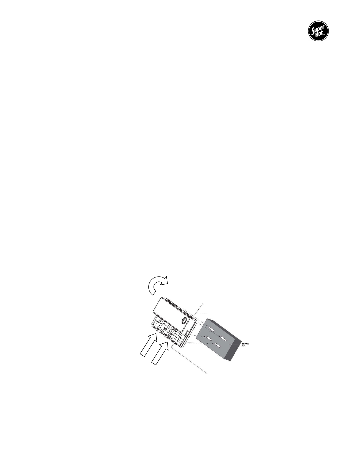
The controller has four tabs which align with four slots in the control panel. To remove the controller, press
and hold in the bottom two tabs while simultaneously rotating the controller about 45 degrees to unhook
the top two tabs.
Rotate 45°
both tabs while
rotating controller
10
Page 7
SG Series Boilers – Installation and Service Manual
Display Code
State
Specific Description
Operation Sequence
Thermostat Calls For Heat
Circulator output energizes
Call For Heat Ends
Vent Damper Operation
Wait for vent damper to
Troubleshooting/Diagnostics
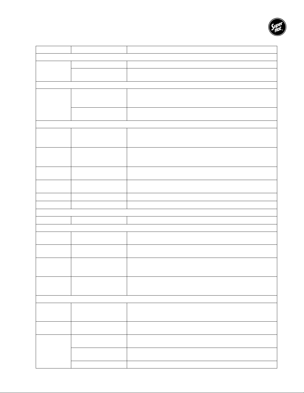
Table 3 - State Codes
Idle/Standby The boiler is in standby - no call for heat.
↔
↔
Run circulator Heat request present but boiler water temperature sufficiently high
to run circulator pump only (no ignition sequence).
Self Test Hardware self check, check of connected periphery, it is
performed at start up, in the beginning of the heat cycle and in the
“Wait For recovery” state.
Wait for recovery There is an external error and the control is waiting to recover, no
lockout.
↔
↔
↔
↔
↔
↔
↔
↔
↔
↔
↔
Wait for end switch to
open
The control is waiting for the end switch of the vent damper to
open at the beginning of a heat cycle. If the end switch doesn’t
open in 60 seconds, the control goes to error code .
Wait for end switch to
close
The control is waiting for the end switch of venting damper to
close at the beginning of a cycle. If the end switch doesn’t close
within 60 seconds, the control goes to error code .
Pump pre-purge/
thermal purge
Spark, ignition
activation
System is purging before ignition trial-safety relay diagnostics
followed safety relay switch-on during last 2 seconds this state.
System is sparking permanently 13 seconds whilst pilot gas valve
relay is turned on.
Prove flame System is proving flame signal, typically 2 seconds.
Running System is in running mode, flame signal must be present.
Pump post-purge System is purging at the end of a call for heat.
Wait for vent damper to
open
Wait for vent damper to
close
Damper actuator is energized and the system waits for damper to
close.
Damper actuator is de-energized and the system waits for damper
to open.
Damper actuator is energized, system waits for damper to open,
open - failed closed
but the damper is stuck in closed position (damper end switch is
open).
Wait for vent damper to
close - failed open
Damper actuator is de-energized, system waits for damper to
close, but the damper is stuck in open position (damper end
switch is closed).
↔
↔
↔
Inter-purge
(retry/recycle delay)
Wait for limit to close
Flame out of sequence
– before trial
Flame out of sequence
– after trial
If the control loses flame signal during state code 7 or 8, or flame
is not detected during state code 6 to 8, it will recycle through the
30 seconds purge time and last 2 seconds part of pre-purge time.
There may be a call for heat from the thermostat, but the limit
switch is open.
Flame signal sensed before trial for ignition.
Flame out of sequence during post-purge.
Wait for flame loss Flame signal still present when not expected.
11
Page 8
SG Series Boilers – Installation and Service Manual
Display
State
Solution
If the controller is displaying “
determine the problem and possible causes.
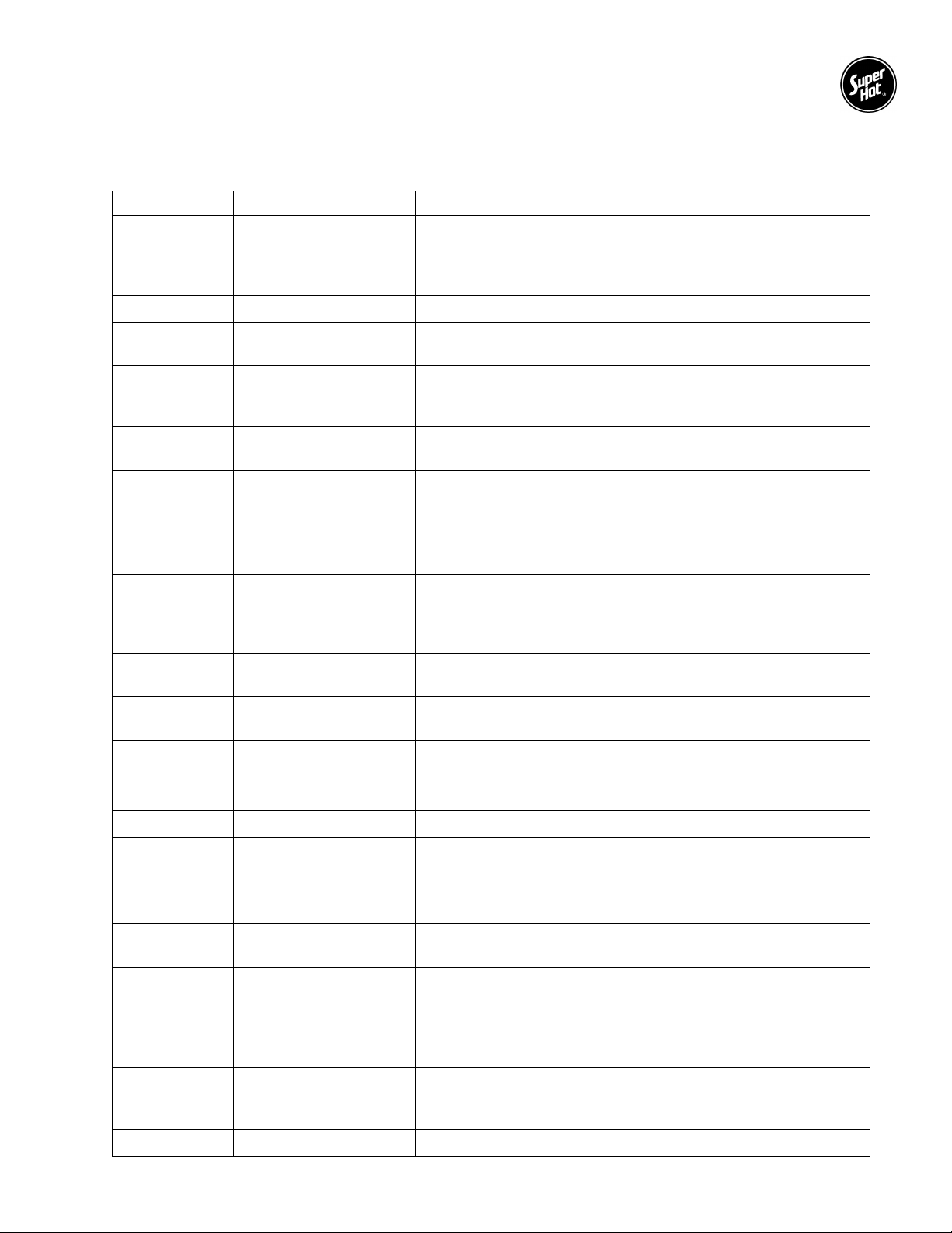
Table 4 - Error Codes
↔
End switch of venting
damper failed to open
↔
↔
Low flame current Check pilot assembly and replace it if necessary.
Flame sensed out of
normal sequence
Gas valve relays
↔
welded 5 consecutive
soft lockouts
↔
↔
↔
↔
↔
↔
↔
↔
Flame sensed during
pre-purge
Flame sensed during
post-purge
End switch of venting
damper failed to close
Sensor error
End switch error
End switch error
Flame rod shorted to
burner ground
AC line frequency error AC signal is too noisy or frequency is incorrect.
” followed by a number, use the error code definitions in the Table 4 to
The end switch of venting damper has not opened at the
beginning of the heat cycle. The end switch contacts are stuck
closed. The control is not in lockout. Check the venting damper
and replace it if necessary.
Flame sensed out of normal sequence (before opening gas
valve or after closing gas valve).
A manual reset is required.
Flame sensed during pre-purge (before gas valve signaled
opened).
Flame sensed during post-purge (before gas valve signaled
closed).
The end switch contacts stuck open. Waiting time for pressure
switch to close expired. The control is not in lockout. Check the
venting damper and replace it if necessary.
Temperature sensor or interface failure (open or short
connection, increased connection resistance, dual sensor
mismatch) or failure of A/D conversion (invalid offset or gain,
too many failures during A/D conversion).
Atmospheric Damper End Switch failed to close (end switch
contacts stuck open).
Atmospheric Damper End Switch failed to open (end switch
contacts stuck closed).
Check and adjust or replace if necessary.
↔
↔
↔
↔
↔
↔
↔
Line voltage error AC voltage out of specification high or low.
Thermostat input
higher than threshold
Line voltage unstable
Soft lockout – Failure to
establish flame signal
Check thermostat wiring and replace it if necessary.
Possibly too many heavy loads switching on and off cause
erratic supply voltage.
Maximum number of retries exceeded. System is shutdown
and will re-start following an enforced delay.
Maximum number of recycles exceeded. Caused by the pilot
Soft lockout – Loss of
flame signal
burner losing flame during running mode, “”. After a 10
second delay, control will attempt to light the burner again
(recycle). If the burner loses flame during the next six recycles,
control progresses to soft lockout ().
Internal failure (Electronics failure). Caused by general
Soft lockout
electronics failure such as relay open or shorted contacts,
flame sensing circuit error, or A to D error.
Over temperature error Sensor measured temperature in excess of ECO limit (230 °F).
12
Page 9
SG Series Boilers – Installation and Service Manual
before placing the boiler in operation or making adjustments to the controller.
1.7 BC-1 CONTROLLER (FOR 2 STAGE BOILERS ONLY)
WARNING
For boilers equipped with the BC-1 Controller, read all instructions in this manual and the BC-1
Controller Manual
Adjustments must be made by a qualified heating technician.
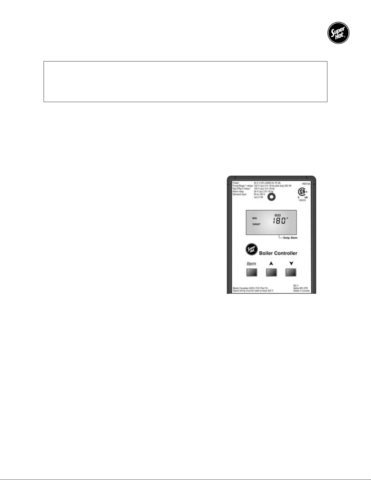
The BC-1 controller is supplied as standard option with two stage boilers for models SG-315 and larger. It
is not supplied with boilers equipped with a full modulating gas valve. For convenience, the BC-1 controller
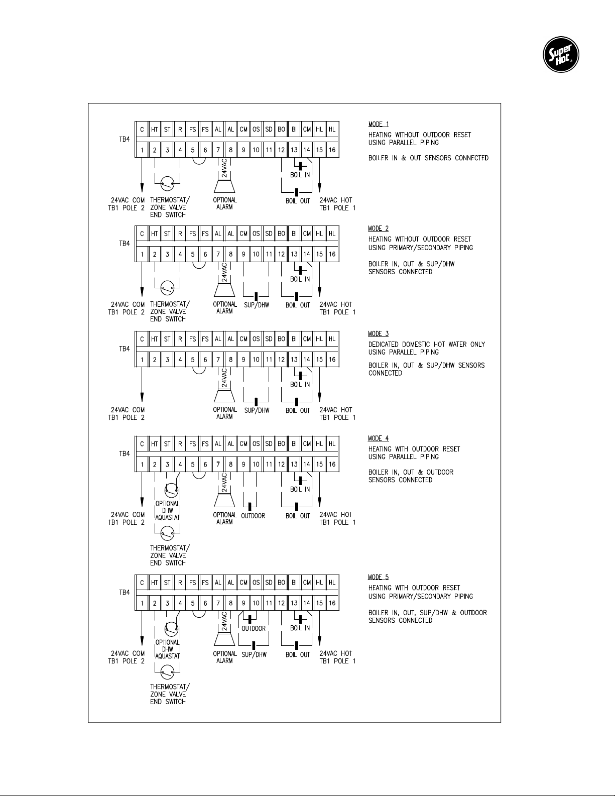
is factory wired to terminal block TB4 and ready for field wiring connections. The field wiring to TB4 is
determined based on the operating mode selected (i.e. mode 1 to 6), the heating application and the piping
arrangement (i.e. parallel or primary/secondary). Refer to Figure 2 for the wiring diagram according to each
mode. For important instructions regarding programming and operation of the BC-1 controller, refer to the
BC-1 Controller Manual included with your boiler.
Power Outputs from BC-1:
Boiler Stage outputs from 15-STG1 and 17-STG2
terminals from the BC-1 are 24 Vac, 60 Hz (when
factory wired).
Alarm output from 23-ALARM terminal from the BC-1 is
24Vac, 60Hz, 0.45A maximum (when factory wired).
Alarm is wired to terminal block TB4, terminals AL&AL.
Signal Inputs (Do not apply external power):
The following signal inputs are located on terminal block TB4:
HT&R: Room thermostat or zone valve end switch,
24Vac switching input, closed is activation.
ST&R: Setpoint DHW aquastat, 24Vac switching
input, closed is activation.
FS&FS: Flow switch, 24Vac switching input, closed
is activation.
Thermistor Sensors:
Figure 2 – BC-1 Controller
BO&CM: Boiler outlet sensor
BI&CM: Boiler inlet sensor
OS&CM: Outdoor sensor
SD&CM: Supply / DHW sensor
BC-1 Controller Mounting
The BC-1 controller mounts on separate bracket on the control panel using a sheet metal screw at the top
center. To remove the controller: 1.) remove the front casing panel, 2.) pull off the black top cover of the
controller, 3.) unscrew the sheet metal screw, 4.) lift the controller slightly out of the rectangular cutout in
the mounting bracket, 5.) pull off the Molex connector while simultaneously holding down the tab on the left
side.
13
Page 10
SG Series Boilers – Installation and Service Manual
Field wiring to terminal block TB4
Figure 3 – Field wiring to terminal block TB4
14
Page 11
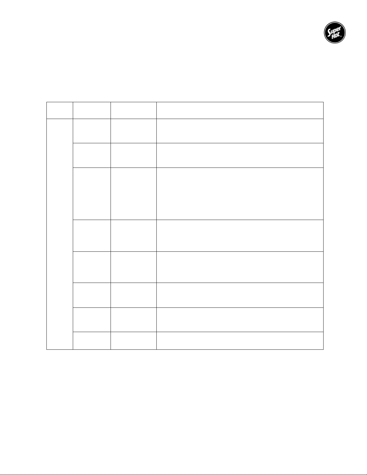
SG Series Boilers – Installation and Service Manual
BO & CM
BI & CM
OS & CM
SD & CM
AL & AL
FS & FS
ST & R
HT & R
Electrical Connections
For all electrical connections: Strip wire ends and insert into the terminal block. Tighten terminal screw
clamps to securely hold the wire.
CAUTION - Risk of damage to the controller - Do not apply power to any connections on terminal
block TB4. 24 Vac has been factory wired to terminals C-1 and HL-15.
Terminal
Block
TB4
Connections Name Description / Comments
Boiler Outlet
Sensor
Connect boiler outlet water temperature sensor to terminals
BO and CM (common). The Boiler Outlet Sensor must be
attached using a cable tie to the boiler outlet pipe.
Boiler Inlet
Sensor
Connect inlet water temperature sensor to terminals BI and
CM (common). The Boiler Inlet Sensor must be attached
using a cable tie to the boiler inlet pipe.
Outdoor
Sensor
Optional Outdoor Sensor (for Mode 4 and 5 only): Connect
Outdoor Sensor 070 to terminals OS and CM (common). The
Outdoor Sensor is installed on an exterior wall, typically
facing North, and above the snow line. It should be shielded
from effects of heat or cold to prevent false outdoor
temperature readings. Avoid direct sunlight, exhaust fans,
appliance vents, and excessive moisture.
Supply/DHW
Sensor
Optional (for Modes 2, 3, and 5 only). Connect a Supply or
DHW Sensor 071 to terminals SD and CM (common). The
Supply/DHW sensor is inserted into a thermowell on the
DHW tank or attached using a cable tie to the supply pipe.
Alarm Optional. The alarm contacts are a powered output, do not
apply power. Connect an alarm (beeper, light, or relay) with
a rating of 24 Vac and maximum 0.45 A to terminals AL and
AL.
Flow Switch Not used. Leave Jumper 5-6 on TB4. For convenience, the
Flow Switch terminals have been relocated to terminal block
TB2, poles T1 & S. Do not apply power.
Setpoint DHW
Demand
Optional Domestic Hot Water Aquastat (for Modes 4 and 5
only): Connect domestic hot water aquastat to terminals ST
and R. Closed is activation. Do not apply power.
Heat Demand Connect Thermostat or Zone Valve End Switch to terminals
HT and R. Closed is activation. Do not apply power.
15
Page 12

SG Series Boilers – Installation and Service Manual
1.7.1 BC-1 CONTROLLER OPERATION
When the controller is powered, the controller enters the operating mode if there are no sensors or high
limit errors present. The user should select one of the following modes from the controller adjust menu:
Mode 1 - Setpoint operation using parallel piping: Operates boiler stages to maintain fixed
temperature at boiler outlet sensor when a heat demand is present.
Mode 2 - Setpoint operation using primary/secondary piping: Operates boiler stages to maintain
fixed temperature at boiler supply sensor when a heat demand is present.
Mode 3 - Dedicated DHW Generation: Operates boiler stages to maintain fixed temperature at the
boiler outlet sensor when an internal demand for DHW is generated based on the DHW sensor. An
indirect hot water tank must be used to isolate the boiler from an open system.
Mode 4 - Outdoor reset with reset override using parallel piping: Operates stages to maintain an
outdoor reset temperature at the boiler outlet sensor. When there is a call for “reset override” from the
DHW aquastat (i.e. ST&R is closed), the control operates the stages to maintain a setpoint temperature
at the boiler outlet sensor. If both heat demand and setpoint DHW demand are present at the same
time, the controller targets the higher of the two requirements.
Mode 5 - Outdoor reset with reset override using primary/secondary piping: Operates stages to
maintain an outdoor reset temperature at the boiler supply sensor. When there is a call for “reset
override” from the DHW aquastat (i.e. ST&R is closed), the control operates the stages to maintain a
setpoint temperature at the boiler supply sensor. If both heat demand and setpoint DHW demand are
present at the same time, the controller targets the higher of the two requirements.
Mode 6 – External boiler control: It is not necessary to use Mode 6 since Direct Digital Control (DDC)
terminals have been provided on terminal block TB1. The DDC terminals may be used for connecting
a boiler or multiple boilers to an external boiler control or an energy management system (EMS). See
boiler wiring diagram for connection details.
When there is a heat demand or DHW demand the controller will switch on the system pump. If the sensor
is not satisfied, the controller will switch stages on, in sequence, based on PID logic (proportional, integral,
derivative). The controller continuously monitors the sensors and examines the difference between the
target temperature and the sensor temperature. Depending on the difference in temperature (proportional),
the time (integral), and how fast or slow the temperature is changing (derivative), it will determine when to
switch a stage on or off. This feature prevents "short cycling", which can quickly wear out components and
cause rapid temperature fluctuations.
The heating routine will operate until the water temperature reaches the user-defined temperature setting.
Once reached, the control will automatically cycle the stage(s) of the boiler on or off, as necessary, to
maintain the supply water temperature. The required number of stages which are activated is determined
by the controller. After the call for heat has been satisfied, the stage(s) of the boiler will switch off, in
sequence, followed by the pump.
1.7.2 RESET OVERRIDE
WARNING
If both Heat Demand and Setpoint DHW Demand are present at the same time, the controller
targets the higher temperature of the two requirements. This may result in higher than intended
water temperatures in either space heating loop or domestic hot water (DHW) heating loop. Use
pipe rated for use at the highest possible water temperature.
The BC-1 Controller has one pump relay which is normally open and will close (i.e. pump energized) when
either a Heat Demand or Setpoint DHW Demand is present. When using Reset Override, a switching
external pump relay (e.g. Tekmar Relay 003) should be utilized to stop hot water flow to the space heating
loop (e.g. radiant in-floor) and redirect it to the DHW heating loop during a Setpoint DHW Demand. See
Figure 4 and Figure 5.
16
Page 13
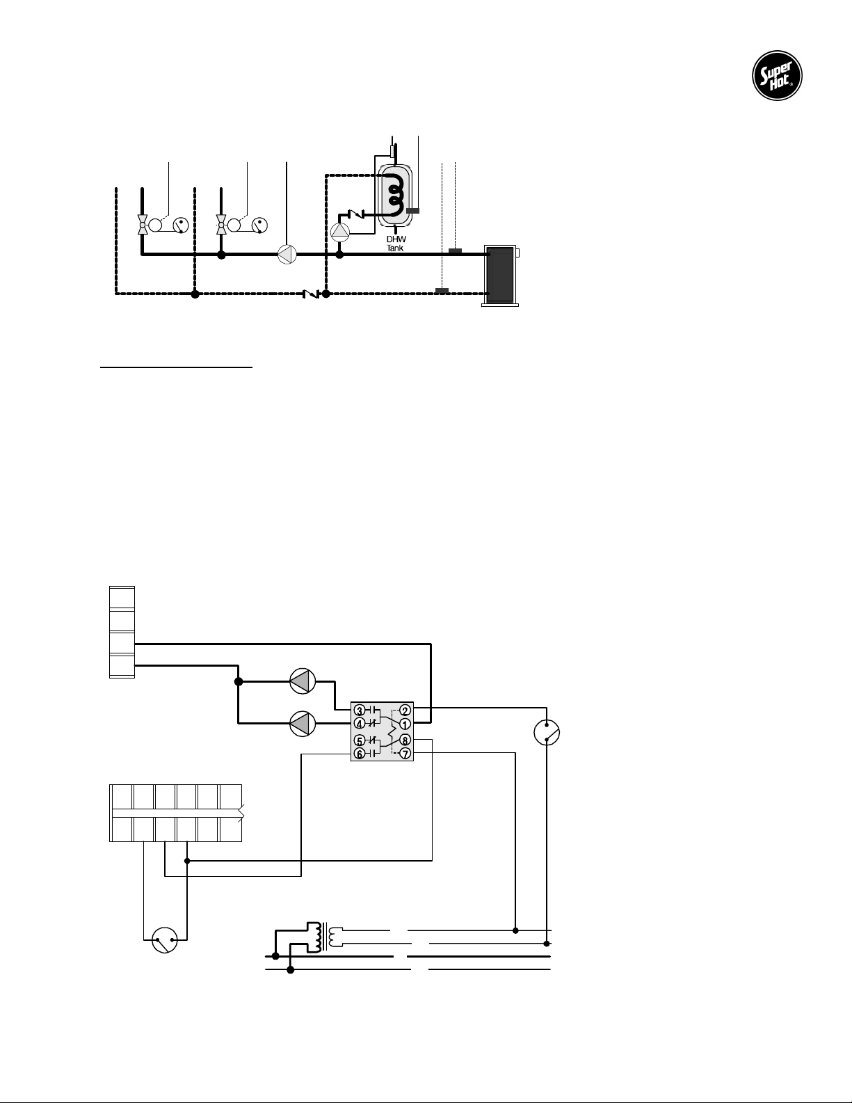
SG Series Boilers – Installation and Service Manual
MODE 4 ONLY
(Outdoor reset and reset override)
1T1T
MM
2Pump
1Pump
1A
1S
S1 = Boiler Outlet Sensor 071
S2 = Boiler Inlet Sensor 071
Pump1 = Boiler Pump
Pump2 = DHW Pump
A1 = DHW Aquastat
T1 = Thermostat
2S
Figure 4 – Typical piping diagram in Mode 4
Sequence of Operation
Thermostat (T1) closed - Thermostat creates a Heat Demand resulting in a boiler target based on the
outdoor reset settings. The boiler pump (Pump1) operates.
DHW Aquastat (A1) closed - DHW Aquastat creates Setpoint DHW Demand and activates external pump
relay. The external pump relay causes the following actions:
1) Power for the boiler pump (Pump1) is broken. Pump1 does not operate.
2) Power for the DHW pump (Pump2) is made. Pump2 operates.
3) Setpoint DHW Demand creates a boiler target based on the higher requirement of the
outdoor reset and reset override setting.
L1
L2
P1
P2
Pump 2
ramket
300yaleR
A1
C HT ST R FS FS
1 2 3 4 5 6
T1
Pump 1
lanretxE
IIssalC
remrofsnarT
42 V
021 V )ca(
C
R
L
N
Figure 5 – Wiring diagram illustrating use of an External Relay to control pump operation
17
Page 14
SG Series Boilers – Installation and Service Manual
Installation Instructions Section 2
2.1 RECEIVING
INSPECT SHIPMENT FOR POSSIBLE DAMAGE. All goods are carefully manufactured, inspected,
checked and packed by experienced workers. The manufacturer's responsibility ceases upon delivery of
goods to the carrier in good condition. Any claims for damage, shortage in shipment or non-delivery must
be filed immediately against the carrier by the consignee.
Use care when receiving and unpacking the boiler. Dropping the boiler may cause damage and prevent
safe and proper operation.
2.2 INSTALLATION CODES AND REQUIREMENTS
All applicable national, provincial/state, and local codes, laws, regulations, and ordinances must be
followed. They expand on and take precedence over any recommendations in this booklet. Authorities
having jurisdiction shall be consulted before installations are made.
In Canada, the installation must conform to the requirements of the authority having jurisdiction or, in the
absence of such requirements, to the CAN/CSA B149 Installation Codes (current edition). All electrical
wiring must be in accordance with the Canadian Electrical Code, CSA C22.1 Part 1 (current edition) and
applicable local codes.
In the United States of America, the installation must conform to the requirements of the authority having
jurisdiction or, in the absence of such requirements, to the National Fuel Gas Code, ANSI Z223.1 (current
edition). All electrical wiring must be in accordance with the National Electrical Code, ANSI/NFPA 70
(current edition) and applicable local codes.
Where required by the authority having jurisdiction, follow the Standard for Controls and Safety Devices for
Automatically Fired Boilers, ANSI/ASME CSD-1 (current edition).
2.3 LOCATION
DANGER – RISK OF EXPLOSION
Do not use or store gasoline or other flammable fuels or chemicals which have flammable vapors near
the boiler. The vapors may be ignited by the heat or electronic components of the boiler.
WARNING
The boiler should be located in an area where water leakage of the boiler or its connections will not result
in damage to the area adjacent to the appliance or to lower floors of the structure. When such locations
cannot be avoided, a suitable drain pan must be installed under the appliance and the drain pan must be
connected to a drain of adequate capacity.
Failure to comply with the above could result in severe personal injury, death or substantial property
damage.
CAUTION
This boiler must be installed such that any electronic components are protected from water (dripping,
spraying, rain, etc.) during appliance operation and service.
18
Page 15

SG Series Boilers – Installation and Service Manual
SG boilers are intended for indoor installation only. Observe the following minimum clearances from the
boiler to combustible materials:
Minimum Clearances to Combustible Materials
Model
SG
Minimum clearance from the boiler front to combustible materials is 6” (153 mm); however, a front
clearance of 24” (609 mm) is recommended for servicing.
Maintain a clearance of 6" (152 mm) from draft hood and the flue pipe in any direction.
Allow ample space for boiler inlet and outlet connections, and gas connection.
Boiler must be installed on a stable and level foundation.
SG Series boilers can be installed on a combustible floor but must not be installed directly on carpeting.
A hot water boiler installed above radiation level must be provided with a low water cutoff device
at the time of boiler installation.
Sides Rear Top Front (service)
in. mm in. mm in. mm in. mm
2 51 2 51 24 610 24 610
2.4 GAS SERVICE PIPING
The boiler and its gas connection must be leak tested before placing the boiler in operation. The gas
controls furnished are suitable for a maximum operating gas pressure of 1/2 psi (14 inches water column).
The boiler and its individual shutoff valve must be disconnected from the gas supply piping system during
any pressure testing of that system at test pressures in excess of 1/2 psig (14 inches water column).
The boiler must be isolated from the gas supply piping system by closing its individual manual shutoff
valve during any pressure testing at test pressures equal to or less than 1/2 psig (14 inches water column).
A manual main shut-off valve should be installed in the gas line outside the boiler jacket and as required in
Section 2.2. The valve should be readily accessible for turning on and off.
A drip pocket or sediment trap should be installed in the gas supply line upstream of the gas controls and
as close to the boiler as possible (example shown in Figure 8 in Section 5).
Some of the pressure regulators or pressure regulating sections of gas valves are provided with an integral
vent limiter and threaded connection. A bleed or gas relief line should be connected to it and piped to the
outdoors.
The pipe compound used should be resistant to the action of liquefied petroleum gases. Check for gas
leaks in piping before placing the boiler in operation by using a soap and water solution. DO NOT USE AN
OPEN FLAME.
INSTALLER MUST IDENTIFY EMERGENCY SHUT-OFF DEVICES.
All piping and fittings must be installed as per codes in Section 2.2.
2.5 AIR SUPPLY FOR COMBUSTION AND VENTILATION
A sufficient air supply MUST be provided to this boiler. Air openings to the boiler room provide the air for
combustion, flue gas dilution and ventilation and are always required, regardless whether the air is taken
from inside or outside. The air opening size and location (as well as other air supply and venting
considerations) must conform to Section 2.2.
The boiler room must never be under a negative pressure. Always provide air openings sized not only to
the dimensions required for the total input of all fuel-fired appliances in the boiler space, but also to handle
the air movement rate of any exhaust fans or air movers using air from the building or space.
The venting terminations must always be kept clear of obstructions (i.e. snow, ice, etc.). Louvers and grilles
used in the air supply and ventilation system should be kept clear of any dust, dirt, or debris which will block
proper air flow.
19
Page 16

SG Series Boilers – Installation and Service Manual
2.6 CORROSIVE ATMOSPHERES
If a gas boiler is to be installed near a corrosive or potentially corrosive air supply, the boiler should be
isolated from it and outside air should be supplied as recommended in Section 2.5.
Chemical vapors from products containing chlorine or fluorine must be avoided. Even though these
chemicals may be safe to breathe, corrosive substances can become liberated when passed through a gas
flame. Even at low concentrations, these chemicals can significantly contaminate the air supply and shorten
the life of any gas burning appliance. The following is a list of some of the products which should be avoided:
bleaches and chlorinated cleaning products
paints and sprays
water softeners (calcium or sodium chloride)
leaking refrigeration equipment
Freon from common aerosol dispensers
These chemicals are especially commons near swimming pools, beauty shops, dry cleaning
establishments, laundry areas, workshops, and garages. The warranty is void when failure is due to
corrosion.
2.7 VENTING
The responsibility of providing a suitable vent of adequate draft capacity and in good usable condition is
that of the gas fitter/installer. Interference with the air supply for the boiler shall be prohibited.
Vent installation and type of gas vent or vent connector MUST follow all applicable national, provincial/state,
and local codes, laws, regulations, and ordinances as described in Section 2.2.
For boilers for connection to gas vents or chimneys, vent installations shall be in accordance with Part 7,
Venting of Equipment, of the National Fuel Gas Code, ANSI Z223.1 or Section 7, Venting Systems and Air
Supply for Appliances, of the CAN/CGA B149, Installation Codes, or applicable provisions of the local
building codes.
The venting shall be supported as required by applicable code(s). Horizontal runs shall slope upward not
less than ¼ inch per foot (21 mm/m) from the boiler to the vent terminal. Vent cannot go horizontally to vent
terminal without a chimney.
This unit must be installed with the factory supplied draft hood in place. The draft hood is a safety device
designed to control chimney drafts that might affect combustion or blow out the pilot. The draft hood
supplied with the boiler must not be altered. The minimum skirt height as indicated on the draft hood must
be maintained.
Vent connectors serving the boiler must not be connected into any portion of mechanical draft systems
operating under positive pressure.
Vent Terminal Information
The minimum distance from the termination of a vent terminal to adjacent public walkways, adjacent
buildings, operable windows and building openings shall be not less than those values specified in the
National Fuel Gas Code, ANSI Z223.1 and/or CAN/CGA Installation Codes.
For proper operation, the vent terminal must be kept free of snow and other debris at all times.
To prevent discoloration and degradation of building materials by flue gases and flue gas condensation,
ensure that the vent terminal is installed clear of nearby obstacles. In all cases, installation shall be in
accordance with code.
Maintain a minimum clearance of 4 feet (1.22 m) horizontally, and in no case above or below, unless a 4
foot (1.22 m) clearance is maintained from electric meters, gas meters, regulators and relief equipment.
20
Page 17

SG Series Boilers – Installation and Service Manual
Removal of an Existing Boiler
When an existing boiler is removed from a common venting system, the common venting system is likely
to be too large for proper venting of the appliances connected to it.
At the time of removal of an existing boiler, the following steps shall be followed with each appliance
remaining connected to the common venting system placed in operation, while the other appliances
remaining connected to the common venting system are not in operation.
a) Seal any unused openings in the common venting system.
b) Visually inspect the venting system for proper size and horizontal pitch and determine there is no
blockage or restriction, leakage, corrosion and other deficiencies which could cause an unsafe
condition.
c) Insofar as is practical, close all building doors and windows and all doors between the space in which
the appliances remaining connected to the common venting system are located and other spaces of
the building. Turn on clothes dryers and any appliance not connected to the common venting system.
Turn on any exhaust fans, such as range hoods and bathroom exhausts, so they will operate at
maximum speed. Do not operate a summer exhaust fan. Close fireplace dampers.
d) Place in operation the boiler being inspected. Follow the lighting instructions. Adjust the thermostat
so the boiler will operate continuously.
e) Test for spillage at the draft hood relief opening after 5 minutes of main burner operation. Use the
flame of a match or candle, or smoke from a cigarette, cigar or pipe.
f) After it has been determined that each appliance remaining connected to the common venting system
properly vents when tested as outlined above, return doors, windows, exhaust fans, fireplace dampers
and any other gas burning appliance to their previous conditions of use.
g) Any improper operation of the common venting system should be corrected so the installation conforms
to the National Fuel Gas Code, ANSI Z223.1 and/or CAN/CGA Installation Codes. When re-sizing any
portion of the common venting system, the common venting system should be resized to approach the
minimum size as determined using the appropriate tables in Part 11 of the National Fuel Gas Code,
ANSI Z223.1 and/or CAN/CGA Installation Codes.
2.8 AUTOMATIC VENT DAMPER (SG-135 to SG-270)
All boilers with an input of 300,000 Btu/h and under are supplied with an automatic vent damper. The
following instructions must be observed:
The automatic vent damper should be installed at the top of the factory supplied draft hood (Figure 1 -
Alternate 3). No modifications to the automatic vent damper are permitted.
The venting system must be arranged so that only the boiler is served by the automatic vent damper
with which it was supplied.
Connect the wiring harness from the boiler to the automatic vent damper as indicated on the supplied
wiring drawings.
The automatic vent damper position indicator should be clearly visible after installation.
A minimum clearance of not less than 6 inches (153 mm) must be maintained between the automatic
vent damper device and combustible construction. Provision must be made for service access to the
automatic vent damper.
The automatic vent damper must be in the open position when the boiler's main burner is operating.
For orientation other than vertical, refer to automatic vent damper installation instructions.
21
Page 18
SG Series Boilers – Installation and Service Manual
Shut down of the boiler by either the “Blocked Vent” or the “Flame Roll-out” safety switch is an
2.9
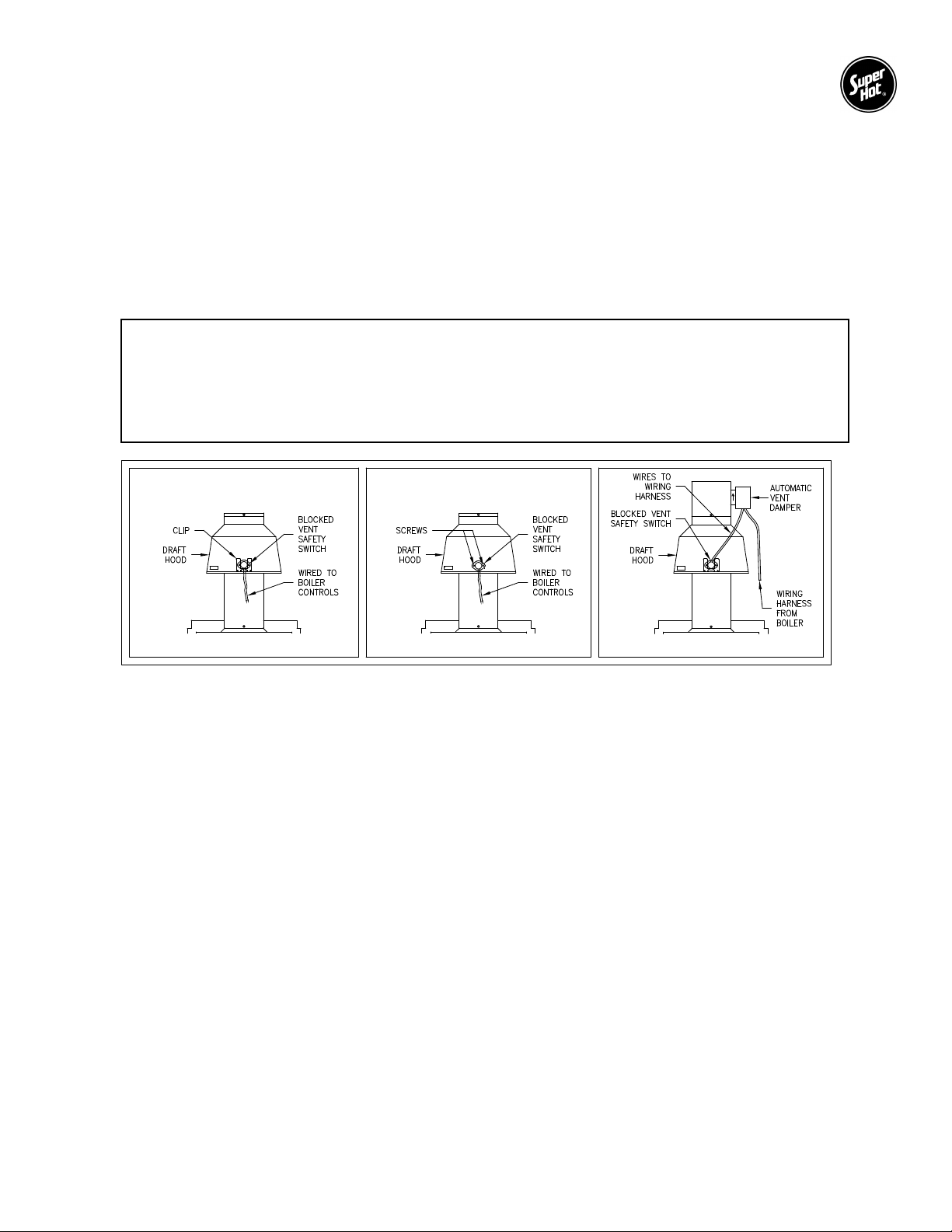
All boilers with an input of 300,000 Btu/h and under are equipped with blocked vent and flame roll out safety
switches. The blocked vent safety switch is installed in the clip provided on the draft hood (Figure 6 Alternate 1) or is mounted with screws (Figure 6 - Alternate 2). The blocked vent safety switch is pre-wired
at the factory either directly to the boiler controls (Figure 6 - Alternate 1 & 2), or through a wiring harness
for a boiler with an automatic vent damper (Figure 6- Alternate 3). If the vent becomes blocked a boiler
shut down will occur. Ensure that the vent is free of obstructions.
The flame roll out safety switch will cause a boiler shutdown if the heat exchanger becomes blocked with
soot or corrosion.
BLOCKED VENT AND FLAME ROLL-OUT SAFETY SWITCHES (SG-135 to SG-270)
WARNING
indication that carbon monoxide may be improperly venting into the premises and the boiler must
be serviced by a qualified person who is capable of determining the cause of the shut down and
can take corrective action. Carbon monoxide is a lethal, colorless and odorless gas.
FIGURE 6 - MOUNTING LOCATION OF BLOCKED VENT SAFETY SWITCH AND WIRE ROUTING
ALTERNATE 1 ALTERNATE 2 ALTERNATE 3
2.10 BOILER PIPING SYSTEM
The boiler piping system of a hot water boiler connected to heating coils located in air handling units where
they may be exposed to refrigerated air circulation must be equipped with flow control valves or other
automatic means to prevent gravity circulation of the boiler water during the cooling cycle.
The boiler, when used in connection with a refrigeration system, must be installed so the chilled medium is
piped in parallel with the boiler with appropriate valves to prevent the chilled medium from entering the
boiler.
2.11 CORROSION PREVENTION (INTERNAL)
The use of oxygen barrier tubing is recommended to protect the system and its components (e.g. pump)
from corrosion. Should your system include "non-oxygen barrier” tubing, please contact the factory or a
heating professional for recommendations.
If freeze protection is required, use an inhibited propylene glycol solution which is specifically designed for
hydronic heating systems and always maintained at a neutral pH (e.g. Fernox Alphi-11 or equivalent).
Follow the supplier’s instructions for proper use and maintenance. Do not use automotive antifreeze.
Some types of chemical additives can cause problems (e.g. accelerated corrosion, reduced efficiency, etc.)
and could result in premature failure of the boiler heat exchanger and/or system components, especially
when not properly used or maintained. Corrosion is a preventable condition and is not covered by the
product warranty.
22
Page 19
SG Series Boilers – Installation and Service Manual
If you do not follow these instructions exactly, a fire or explosion may result causing property
The pressure relief valve discharges pressurized hot water and/or steam. Steam exiting the
2.12 SYSTEM OPERATING REQUIREMENTS
WARNING
damage, personal injury or loss of life.
Avoid unnecessary replenishment of system water. It can allow oxygen to enter the system and cause
serious corrosion problems. As well, minerals dissolved in the water supply will precipitate when heated;
minerals preferentially deposit in the heat exchanger. Do not draw water from the heating system for
cleaning, flushing, etc.
Super Hot SG series boilers are designed for use in closed loop systems and are not intended for open
systems, as in heating pool water or systems where water is constantly replenished. Operating the boiler
in an open system will result in premature failure of the heat exchanger. Super Hot boilers may be used
to heat water in open systems indirectly by installing a heat exchanger, such as the Super Hot C-Coil, to
separate open and closed systems.
Heating systems with low temperature return water may cause flue gas moisture to condense on the boiler
heat transfer surfaces, causing corrosion and restricting flue gas flow. Also, low temperature return water
may overcool the flue gases, resulting in reduced vent suction. These are natural phenomena and are
independent of the boiler design. As a guide to avoiding such corrosion and draft problems, it is imperative
that the return water be not less than 135°F (57°C).
SG SERIES BOILERS MUST ALWAYS BE USED WITH FORCED SYSTEM CIRCULATION.
2.13 WATER QUALITY
Always use good quality water to prolong the life of the boiler. Water that is safe to drink and even city water
is not necessarily good quality water for the boiler. The use of water treatment and filters can prevent
corrosion and reduce sediment in the boiler. Water hardness, pH, and chlorides must be controlled to
normal levels.
PH levels must be between 6.0 and 8.0
Chlorine, chloride and sulfate concentrations must be below 100 parts per million.
If you are unsure, use a water softening system or consult a qualified water treatment expert.
NOTE: All improper use as detailed above could void the warranty of the boiler.
2.14 PRESSURE RELIEF VALVE
WARNING
discharge outlet can explosively expand in any direction. Always maintain a safe distance from
the discharge pipe outlet in order to avoid potential contact with exiting hot water or steam.
A pressure relief valve is supplied as standard equipment. The pressure relief valve is extra protection
against damage that could be caused by malfunctioning controls or excessive water pressure. If a pressure
relief valve is not used, the warranty is void.
The pressure relief valve should be installed on the boiler outlet with its spindle vertical. The connection
between the boiler and the relief valve must have at least the area of the valve inlet.
A discharge pipe should be used. The discharge pipe outlet should be positioned over a suitable drain and
so arranged that there will be no danger of being scalded. The discharge pipe must pitch down from the
valve and should be no smaller than the outlet of the valve. The end of the discharge pipe should not be
concealed or threaded and should be protected from freezing. Extensive runs, traps or bends could reduce
the capacity of the pressure relief valve.
23
Page 20
SG Series Boilers – Installation and Service Manual
This boiler may be connected to more than one electrical circuit. Disconnect all electrical power
The following instructions are intended as a guide for qualified persons. Before lighting the
No valve of any type should be installed between the pressure relief valve and unit or in the discharge pipe.
The pressure relief valve is a code requirement. Field installation of the relief valve must be consistent with
the ANSI/ASME Boiler and Pressure Vessel Code, Section IV.
2.15 ELECTRICAL WIRING
DANGER – RISK OF ELECTRIC SHOCK
before installation or service. All circuit breakers ahead of and at the boiler must be off. Failure
to do so may result in severe personal injury or death.
All electrical wiring must conform to the requirements in Section 2.2.
Run a separate circuit from the electrical service panel through a fused disconnect switch to the boiler. This
boiler must be electrically bonded to ground in accordance with the requirements of the authority having
jurisdiction or, in the absence of such requirements, with the National Electrical Code, ANSI/NFPA 70
(current edition) and and/or the Canadian Electrical Code, CSA C22.1 Part 1 (current edition). Field wiring
shall conform to Section 2.2 and to the temperature limitations of Type T [63F (35C) rise] or better.
Make connections as shown in the wiring diagram provided with this manual. Also, a wiring diagram sticker
is provided on the inside of the door panel of the boiler.
Startup Instructions Section 3
3.1 PRE-STARTUP
a. Fill entire heating system with water and vent or purge air from system. Add water as needed to reach
boiler operating pressure. Water should be of suitable quality. Do not use water with high hardness.
b. Check for and repair any leaks in water piping.
c. Check burners to see that they are not dislodged.
d. Check for proper installation of pressure relief valve, draft hood, and venting.
e. Check that the electrical wiring matches the wiring diagram in this manual or on the boiler.
f. Check if the flame roll out safety switch and blocked vent safety switch are properly located and wired.
(Applicable on models SG-135 to SG-270)
g. Use a soap solution to check for leaks in gas piping from meter to boiler pilot and manifold. Repair and
retest any leaks found.
h. Operate circulating pump and vent all radiation units and high points in system piping.
3.2 STARTUP
WARNING
boiler, the pre-startup instructions of Section 3.1 MUST be performed. If you do not follow these
instructions exactly, a fire or explosion may result causing property damage, personal injury or
loss of life.
24
Page 21

SG Series Boilers – Installation and Service Manual
Should boiler overheat, or the gas supply fail to shut off, do not turn off or disconnect the
WARNING
electrical supply to the circulating pump. Instead, shut off the gas supply at a location external
to the boiler.
a. Intermittent pilot with combination gas valve
This boiler does not have a continuous pilot flame. It is equipped with an ignition device which automatically
lights the pilot. Do not try to light the pilot by hand.
In the event of failure of any component, either the system will not operate or it will go into safety lockout.
1) Make sure the Gas Valve and all electrical power to the boiler is "OFF".
2) Set room thermostat to the lowest setting.
3) Connect a manometer at pressure tapping on downstream section of gas valve.
4) Wait five minutes to clear out any gas. If you smell gas, STOP! Follow the safety instructions
5) Set the controller as described in Section 1.6 and check operation as follows:
6) Turn Gas Valve to ON. Pilot burner should ignite, followed by main burners. Check main and pilot
7) Assure that all other gas appliances are turned off, including their pilot flames.
8) Check manifold pressure reading on the manometer and make necessary adjustments. Check that
9) Return thermostat and controls to normal operation settings.
provided in Section 1.1 under WHAT TO DO IF YOU SMELL GAS. Remember that propane does
not vent upward naturally.
a) Set thermostat above room temperature to call for heat and turn power on for the boiler.
b) Watch for spark at pilot burner. All models will automatically lockout if no pilot flame is detected
within 15 seconds. Automatic retry will occur in 5 minutes.
burners and adjust pilot, if necessary, as described in Section 3.3.
burner input matches rating plate input.
b. Intermittent pilot with non-combination gas valve
This boiler does not have a continuous pilot flame. It is equipped with an ignition device which automatically
lights the pilot. Do not try to light the pilot by hand.
In the event of failure of any component, either the system will not operate or it will go into safety lockout.
1) Make sure the Main and Pilot Gas Valve and all electrical power to the boiler are "OFF".
2) Set room thermostat to the lowest setting.
4) Connect a manometer at pressure tapping on downstream section of gas valve.
4) Wait five minutes to clear out any gas. If you smell gas, STOP! Follow the safety instructions
provided in Section 1.1 under WHAT TO DO IF YOU SMELL GAS. Remember that propane does
not vent upward naturally.
5) Check the ignition control module as follows:
a) Set thermostat above room temperature to call for heat and turn power on for the boiler.
b) Watch for spark at pilot burner on units equipped with spark ignition. All models will
automatically lockout if no pilot flame is detected within 15 seconds. Automatic retry will occur
in 5 minutes.
6) Turn Pilot and Main Gas Valve to ON. Pilot burner should ignite, followed by main burners. Check
main and pilot burners and adjust pilot, if necessary, as described in Section 3.3.
7) Assure that all other gas appliances are turned off, including their pilot flames.
8) Check manifold pressure reading on the manometer and make necessary adjustments. Check
burner input to match rating plate input.
9) Return thermostat and controls to normal operation settings.
25
Page 22
SG Series Boilers – Installation and Service Manual
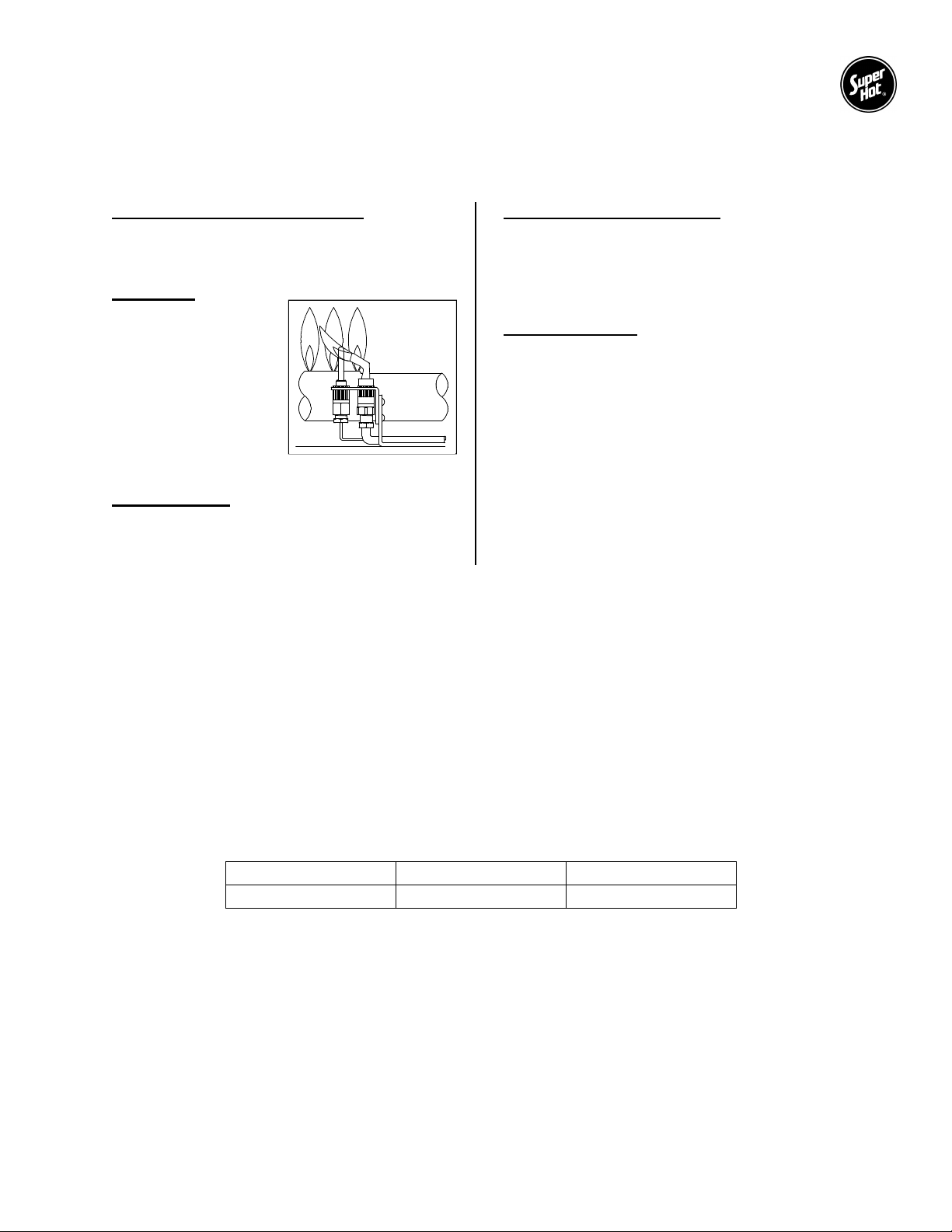
FIGURE 7 - PILOT FLAME
3.3 CHECK BURNER SYSTEM
To maintain safe and efficient operation, examine the burner system regularly through the inspection hole
near the pilot tube.
Check condition of burner system
It is possible for parts of the burner system to
become plugged, cracked, eroded and/or
dislodged resulting in unsafe operation.
Pilot Flame
Remove cap screw
cover on gas or pilot
valve, and then adjust
gas flow to the point
where sensor rod is
completely enveloped
by the flame (Figure 7),
but not necessarily
glowing red. Replace
and tighten cap.
Check for lifting
ADJUSTMENT
Flames should not lift excessively from the burner
Check ignition and extinction
Ignition should flow quickly and smoothly across
all the burners. Popping noises or explosions
from the burners during ignition, extinction or
normal burner operation indicates the need for
service.
Check flame color
An extremely yellow flame, as seen on a burning
candle or match, is an indication of incomplete
combustion and is usually accompanied by the
formation of soot and carbon monoxide (carbon
monoxide is a lethal, colorless and odorless gas).
If soot is allowed to accumulate, it will partially
restrict free passage of products of combustion to
the flue. Under typical operating conditions, the
flame should have a distinct bright blue inner
cone and a blue/orange outer cone.
ports. The flames may lift slightly during ignition
or when the burners are cold.
If any of the above problems are observed or the burner system does not operate properly,
immediately take corrective measures.
3.4 AQUASTAT ADJUSTMENT
An optional aquastat may be installed to control the main burner firing by sensing outlet water temperature.
The optional aquastat should be set a minimum of 20°F (10°C) above the setting of the high limit of the
integrated boiler controller.
3.5 GAS MANIFOLD PRESSURE
The designated manifold pressures are as shown in the table below. A 1/8” NPT tapping is provided on
the manifold or gas valve for connecting a manometer to check this pressure. Both natural gas and propane
models are furnished with gas valves which have a built in gas pressure regulator. If necessary, adjust to
the proper value by removing cap and turning adjusting screw clockwise to increase manifold pressure or
counterclockwise to decrease manifold pressure.
Model Natural Gas Propane
SG
3.5” W.C. 10.0” W.C.
26
Page 23
SG Series Boilers – Installation and Service Manual
Exceeding the allowable input rate can produce dangerous concentrations of carbon monoxide,
3.6 CHECK INPUT & ORIFICES
For safety, the input shown on rating plate must not be exceeded. Check with the table below that the
orifice size and input rate shown on the rating plate match your application, i.e. boiler model, fuel type, and
altitude. See SG Dimensions and Specifications section to find your boiler model's input rate.
FOR CANADA
Model
0 to 2,000 feet 2,000 to 4,500 feet 0 to 2,000 feet 2,000 to 4,500 feet
Natural Gas Propane
SG
NOTE: For elevations above 4,500 feet reduce high altitude input 4% for each additional 1000 feet.
Reference Natural Gas and Propane Installation Code B149.1, 3.22 High Altitude Installations
#43 orifice
standard input
#44 orifice
10% de-rate input
#54 orifice
standard input
#55 orifice
10% de-rate input
Example of High Altitude De-rate
Boiler: SG-270
Altitude: 5,500 feet
Standard Input (0 to 2,000 ft) = 270,000 Btu/h (from page 3)
High Altitude Input (2,000 to 4,500 ft) = De-rate Standard Input by 10% (see above
table)
= 270,000 Btu/h x (1 - 0.10)
= 270,000 Btu/h x 0.90
= 243,000 Btu/h
% Reduction for additional 1000 ft = 4% x 1 = 4%
Input at 5,500 ft = De-rate High Altitude Input by 4%
= 243,000 Btu/h x (1 – 0.04)
= 243,000 Btu/h x 0.96
= 233,280 Btu/h
FOR UNITED STATES OF AMERICA
Natural Gas Propane
Model
0 to 2,000 feet Over 2,000 feet 0 to 2,000 feet Over 2,000 feet
SG
*Reference National Fuel Gas Code ANSI Z223.1, 8.1.2 High Altitude.
#43 orifice
standard input
Input must be reduced
4% for each 1000 feet
above sea level. *
#54 orifice
standard input
Input must be reduced
4% for each 1000 feet
above sea level. *
Small adjustments to the input rate can be made by varying the manifold pressure. Normally it should be
adjusted no more than 0.2 inch w.c. for natural gas or 0.5 inch w.c. for propane from the manifold pressure
specified on the rating plate.
DANGER
and cause the boiler to overheat resulting in severe personal injury, death or substantial property
damage. Carbon monoxide is a lethal, colorless and odorless gas.
27
Page 24
SG Series Boilers – Installation and Service Manual
Continuous spillage at the draft hood relief opening may result in severe personal injury, death
Input Rate Test
Consult gas company to determine the heating value of the gas supplied in Btu per cubic feet. Operate
boiler for 15 minutes starting with all parts at room temperature and check input by clocking gas meter with
all other gas appliances turned off, including their pilot flames. Use the following formula:
INPUT (Btu/h) =
To ensure accuracy for rating, clock enough cubic feet of gas so that there is at least one revolution of the
test dial and the clocked time is at least 60 seconds.
Two Stage or Full Modulating Gas Valve
When a two-stage or modulating gas valve is used, it must be checked for correct input at both "High" and
"Low" fire settings. The clocked input rate MUST be within the "Minimum Input" and the "Input" as specified
on the boiler's rating plate. To force a two-stage or full modulating gas valve to low fire, see the valve
manufacturer's instructions. Perform the Input Rate Test described above and adjust manifold pressure of
High and Low settings as necessary. For altitudes above 2000 feet, DO NOT de-rate the "Minimum Input"
rate.
3.7 CHECK FOR DRAFT HOOD SPILLAGE
Seconds in Time Clocked
Timed) FeetCubic of (Volume x )Btu/cu.ft. in Gas of ValueHeating (High(3600)
WARNING
or substantial property damage.
After the main burners have operated for 5 minutes, check to see that combustion products are going up
the chimney or gas vent properly by passing a lighted match (or smoke from a cigar, cigarette, or pipe)
around the edge of the relief opening of the draft hood. If the chimney or gas vent is drawing properly, the
match flame or smoke will be drawn into the draft hood. If not, the combustion products will tend to
extinguish this flame. While performing this test, make sure all exhaust fans, air movers, and gas appliances
are operating and doors and windows are closed. If the combustion products are escaping from the relief
opening of the draft hood, IMMEDIATELY shutdown the boiler and make proper adjustments or repairs.
3.8 CHECK OF CONTROLS
While the boiler is in operation, lower the high limit setpoint () on boiler controller or aquastat setting (as
applicable) below the current outlet water temperature. The burners should shut off. Set the high limit
setpoint () or aquastat setting higher than the current outlet water temperature and the burners should
re-ignite. Return the hi-limit setpoint () or aquastat to its original setting and make sure boiler cycles
normally. Repeat this type of check on the optional aquastat (when used), thermostat and other system
controls to ensure all are working satisfactorily. If any of the safety or controls do not function, necessary
corrections should be made immediately.
3.9 CHECK FOR GAS LEAKS
To identify gas leaks, smell for gas around boiler area and gas piping connections (See Section 1.1). To
check a specific area for leakage, spray a mixture of soap and water onto the suspected area – active
bubbling indicates a gas leak. DO NOT TEST FOR LEAKS WITH AN OPEN FLAME. Gas leaks must be
repaired immediately.
28
Page 25

SG Series Boilers – Installation and Service Manual
Operate the boiler for 15 minutes, then clock and calculate Btu/h input rate.
3.10 INSTALLER'S CHECKLIST
The information printed on the boiler rating plate matches the application (i.e.
input, altitude and fuel type).
All applicable electrical codes have been met.
Gas piping has been purged and checked for leaks with a soap solution.
System is filled with water and all air has been purged. Only oxygen barrier
tubing has been used.
A manometer has been used to check the manifold pressure and gas supply
pressure against requirements printed on boiler rating plate.
Bypass or mixing valve has been used to prevent return water less than 135F.
All applicable venting codes have been met. Air openings sized to provide
adequate supply air for combustion, flue gas dilution and ventilation and will
not be blocked off.
Check for spillage at draft hood and other areas susceptible to spillage.
The input rate must not exceed that specified on the boiler rating plate.
Clocked BTU/H Input Rate: ______________
Perform check of temperature controls: aquastat, optional aquastat (when
used), and thermostat.
Test any other controls as specified by the manufacturer.
Visually inspect main burners and pilot to ensure proper flame operating
characteristics and ignition/extinction is ok.
Allow the boiler to cycle a few times to ensure functions are operating correctly.
Close main and pilot shut-off valve and check that burners and pilot flame
extinguish.
Clearly identify emergency shut-off devices and make the user or owner aware
of their location and method of operation.
Fill in the contact information on the cover of the User's Information Manual
and leave both manuals in the envelope adjacent to the boiler.
Reference
Section
3.6
2.2, 2.14
2.2, 2.4, 3.9
2.11, 2.12
3.2, 3.5
2.12
2.2, 2.5, 2.6, 2.7
3.7
3.6
3.4, 3.8
3.3
NOTE: INSTALLER'S RESPONSIBILITY
"Before leaving installations, installers shall ensure that an appliance, accessory, component, equipment,
or piping and tubing installed by them comply with the Code requirements, and the person initially activating
the appliance shall ensure that the appliance is in safe working order."
CSA B149.1-05 Natural Gas and Propane Installation Code
29
 Loading...