

Page 1
1
rev 1 7/2016
Page 2
Table of Contents
Overview
Firmware
Flight Controller
Radio Control
Failsafe
3
4
5
6
7
Motors, Props, ESCs
Side Plates
Battery
FPV System
Accessories
8
11
18
19
22
Specifications
23
2
rev 1 7/2016
Page 3

overview
…the next evolution of high performance racing drones
Impact resistant composite frame core!
4mm carbon fiber booms!
Fully integrated power and signal PCBs!
24k gold plated connectors and bus bar!
Seriously Dodo rev. 3a F3 flight controller!
Runcam Swift FPV 600TL CCD camera!
200mW RaceBand video transmitter w/ display
Integrated MinimOSD Micro!
Race-spec 2205 2300kv hollow shaft motors!
Flycolor 30A SiLabs F330 ESCs!
Internal battery bay!
14 programable RGB LEDs!
12 high intensity solid red rear LEDs!
Integrated Frsky XSR micro receiver connector
3
rev 1 7/2016
Page 4

Firmware
External Resources
While drone racing is fast and exciting, this new
sport is not without its challenges. The only thing
Cleanflight Firmware & Configurator Software!
http://cleanflight.com/
Betaflight Flight Control Firmware (installed in the AR25)!
https://github.com/betaflight/betaflight
Betaflight Configurator!
https://github.com/betaflight/betaflight-configurator
MW OSD Firmware & Configuration Software!
faster than a racing drone are the advancements and
improvements to the software and firmware!
That being said, the AR25 comes fully configured
and tuned out of the box and should fly just fine for
most users. But for those looking to try to get the
most out of their hardware, these following resources
http://www.mwosd.com/
BL Heli ESC Firmware & Configuration Software!
https://blhelisuite.wordpress.com/
SiLabs Drivers for Flight Controller & ESCs!
http://www.silabs.com/products/mcu/pages/usbtouartbridgevcpdrivers.aspx
are worth exploring and studying in depth.
So to stay on top of the latest developments, keep
an eye on these sites listed here as well as
allieddrones.com for tutorials, support, and more.
4
rev 1 7/2016
Page 5

flight Controller
Seriously Dodo Rev 3a
8 input channels !
We have fully integrated the best flight controller
currently on the market, the Seriously Dodo rev. 3a.
This is a new F3 generation of flight controllers
8 output channels!
3 UARTs (GPS, Telemetry, S.bus)!
2-6s input power 30v MAX INPUT!
5v output - 0.5A Max!
STM32 F303 256k !
2 megabyte blackbox storage!
Barometer!
Spektrum satellite port!
enables fast loop times and multiple UART ports.
The Dodo board interfaces with an AR25 flight
controller adapter board on the right side plate. This
adapter board allows for several additional
configurable solder pads to enable additional
advanced flight controller/RC features such as FC
OSD, Spektrum Rx, Frsky S.port, S.bus, and more.!
!
MPU6050 accelerometer/gyro!
5.4g!
MicroUSB socket!
WS2811-style LEDs pinout!
Preconfigured with Betaflight firmware
The flight controller is pre-configured with Betaflight
and S.bus for the optional Frsky XSR receiver, as well
as the full set of 14 RGB LEDs.
The FC adapter board allows for future additional
flight controller integration.
5
rev 1 7/2016
Page 6
RADIO CONTROL
RC Transmitter & Mode Controls
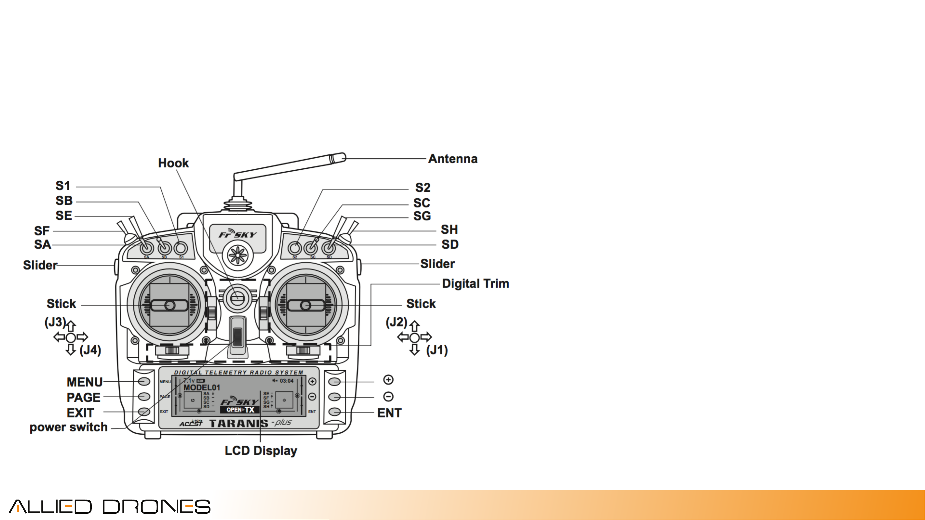
The AR25 has been setup to work nativley with the
FrSky Taranis X9D Plus and XSR s.bus receiver. If you
purchased an ARF package from Allied Drones, then
your receiver has been setup as indicated:
SF - Disarm / Arm!
SH - Off / Momentary Buzzer!
SG - Mode (Angle - Horizon - Rate)!
SD - Airmode Off / AirMode On!
Failsafe - no pulse!
Mode 2 stick configuration
“Home” position for all switches are forward/away
from the perspective of the pilot. Therefore, home
position would be; motors disarmed, buzzer off,
angle mode, airmode off.
6
rev 1 7/2016
Page 7

FAILSAFE
Failsafe Mode
In the event of a loss of radio control signal, both the
radio transmitter (if included) and the flight controller
have been set with basic failsafe mode functionality.
In the event of a lost link between the transmitter
and the RC receiver onboard the RC system is
configured to send “no pulses”. In turn, the flight
controller is configured for both Stage 1 and Stage 2
failsafes if it receives no pulses from the RC receiver.
7
rev 1 7/2016
Page 8
Motors / Props
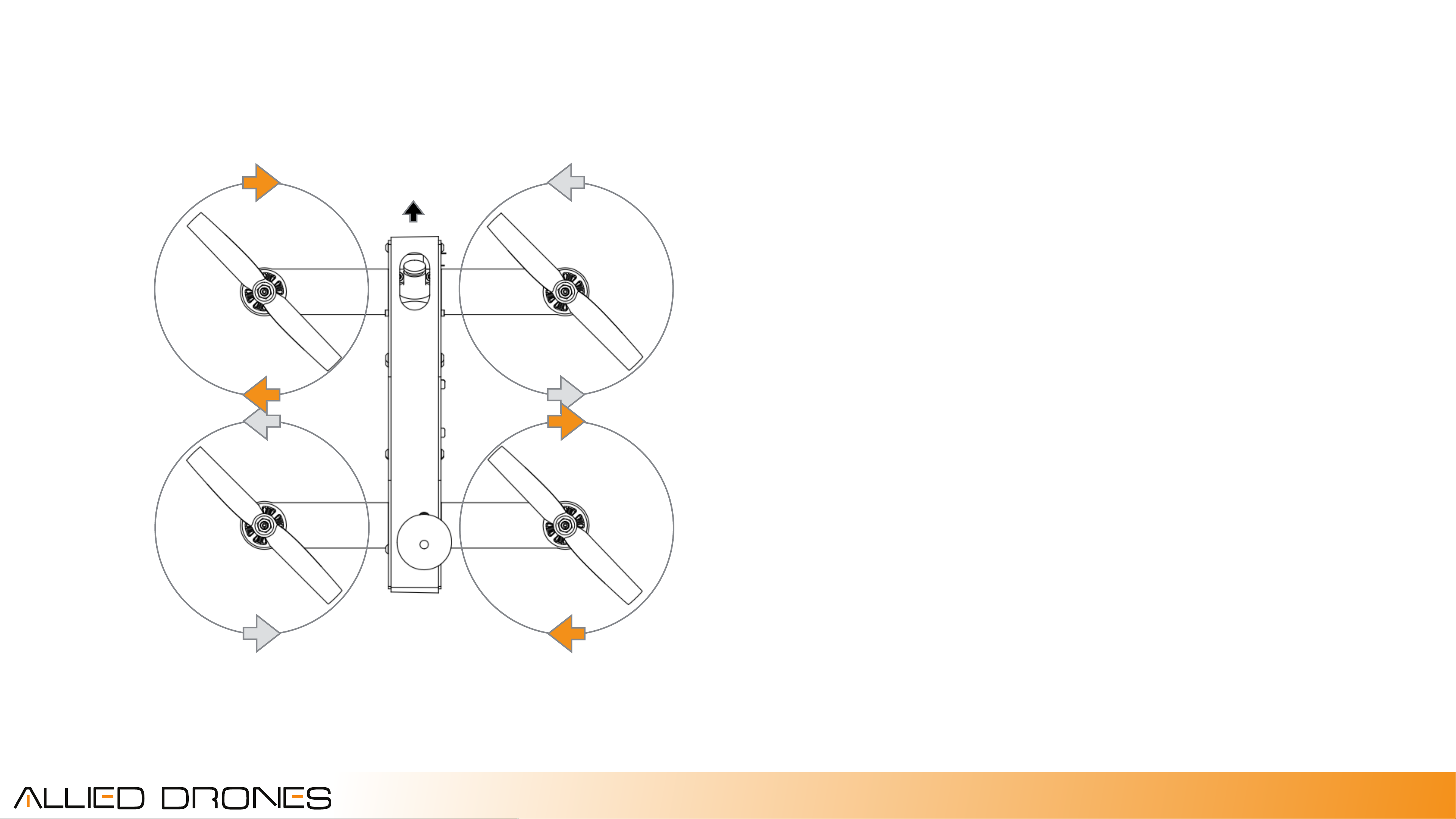
M4 (CW)
M2 (CCW)
The motor and propeller direction and numbering is
critical for the flight of the AR25. Each set of ESC/
M3 (CCW)
Motor solder tabs are labeled on the side plates.
Because each ESC is fully configurable through the
flight controller via USB, we recommend not
worrying about the order in which the ESC output
and motor leads are wired into the plates because
M1 (CW)
we can change it in firmware faster than soldering.
NOTE: However, DO pay attention to ESC input wire
+/- wiring!
When replacing motors, props, and ESCs, please
make note of the proper direction and motor
number position.
8
rev 1 7/2016
Page 9
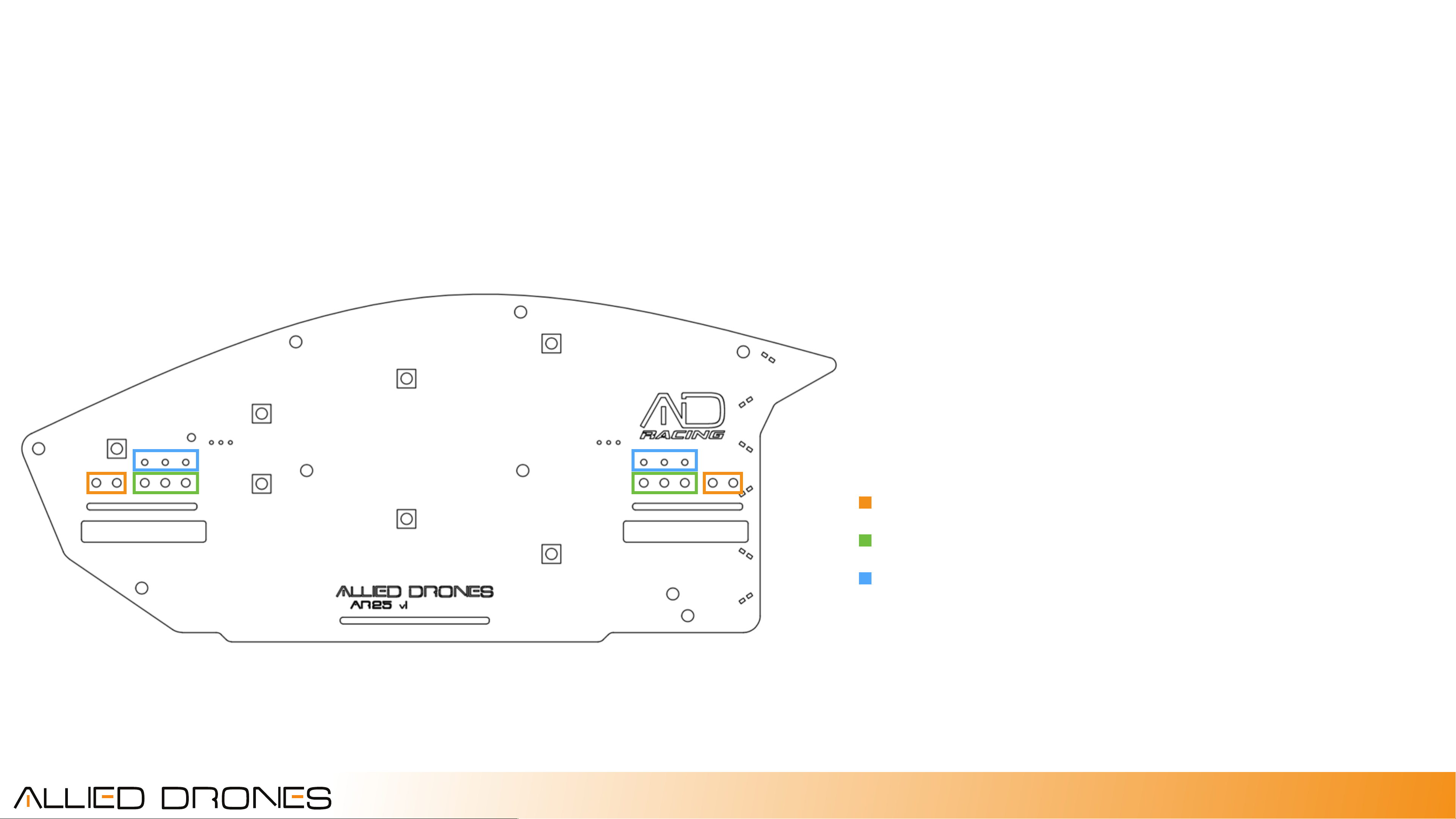
ESC / Motors
Motor direction can be changed either by
exchanging the position of any 2 motor or ESC
leads, or can be done in firmware via a simple
software configuration. After replacing motors or
ESCs, remove the props, power on, and arm the
motors. Note the direction they spin and make
adjustments to the wiring or firmware to reverse
direction.
ESC Power (check polarity!)
ESC Motor Leads
Motor Leads
9
rev 1 7/2016
Page 10
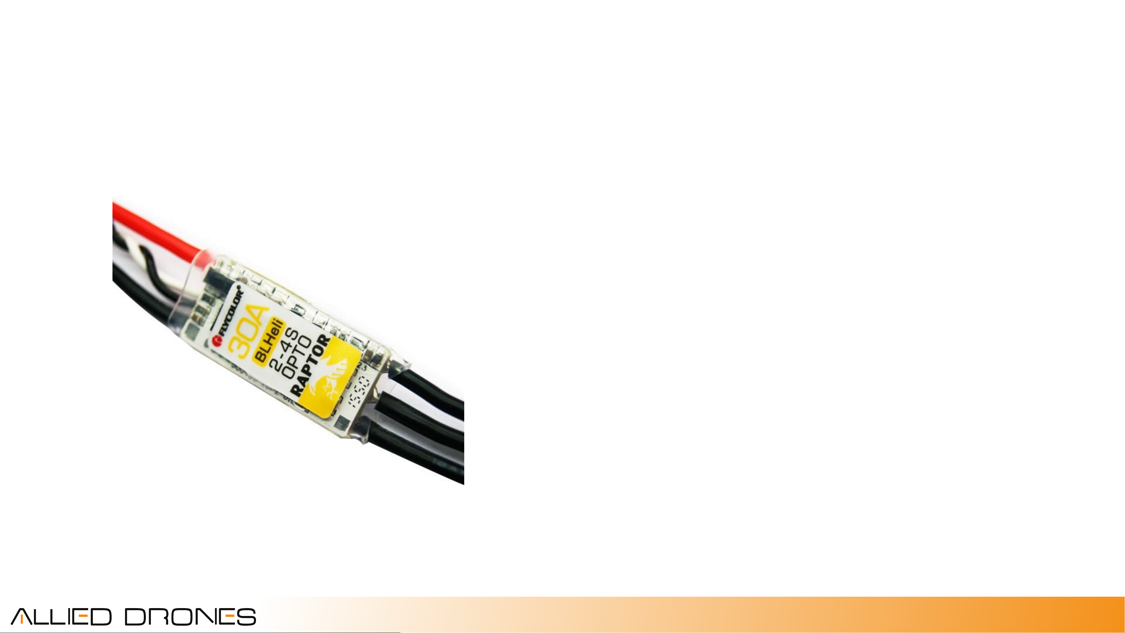
ESC
The ESCs supplied with the AR25 are Flycolor Raptor
30a model number W-FW020004.
Specifications:!
Constant Current Rating: 30A!
Burst Current Rating (10s): 40A!
BEC: No!
Cells: 2-4S!
Weight: 9.6g!
Processor: SiLabs F330!
Firmware: BLHeli 14.4
BLheli Options Set:!
Dampened Light: On!
Oneshot125: On
10
rev 1 7/2016
Page 11
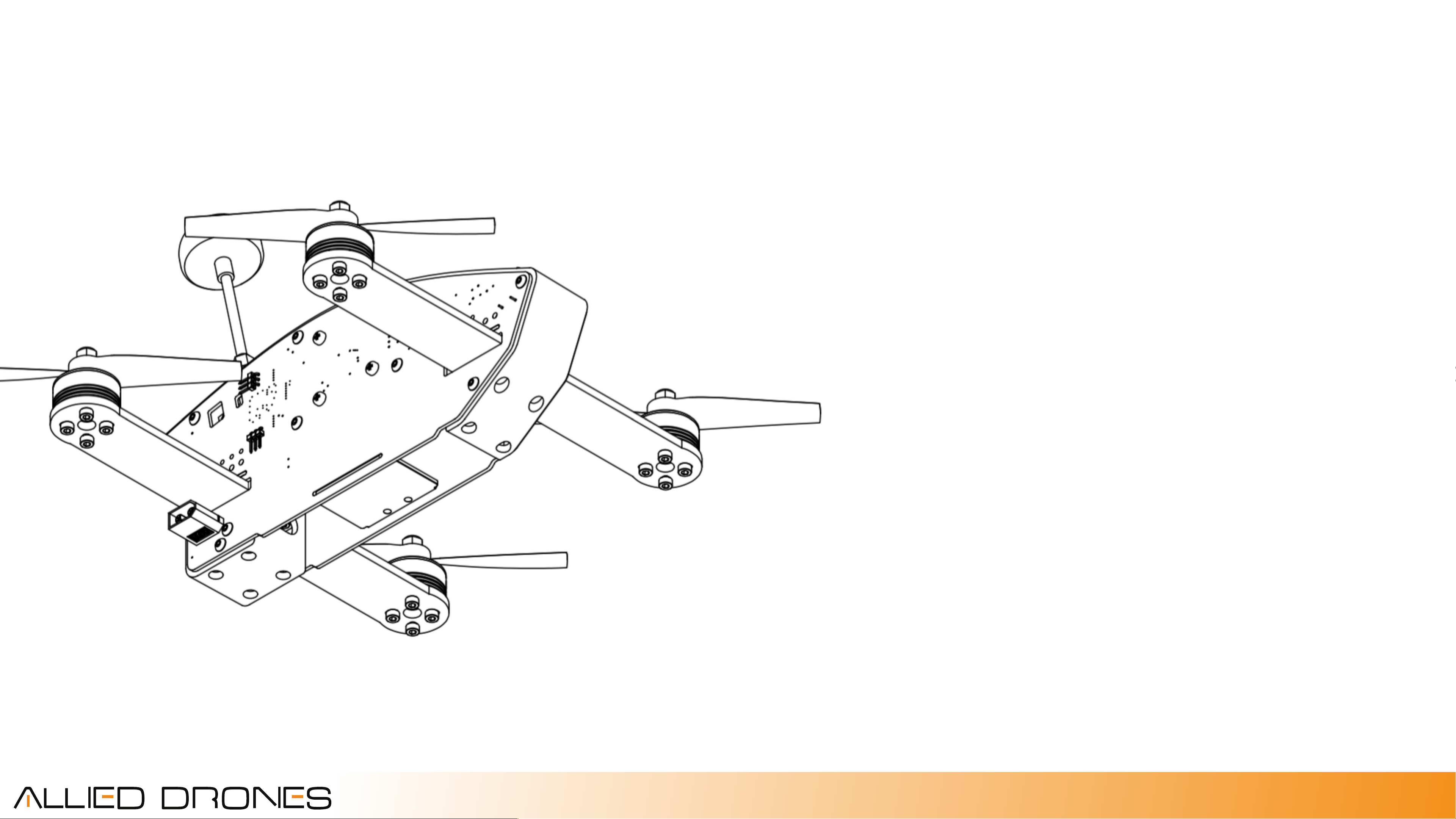
side plates
The AR25 side plates feature integrated RGB and
rear facing red LED lights, power and signal
distribution, integrated 5v regulated power supply,
an audible buzzer, XT60 power connector, an
auxiliary 5v power pinout, gold plated contacts,
solder-less/tool-less internal component connectors,
OSD mounting and external FTDI programming
pinouts, easily accessible motor/ESC solder pads,
and internal LC video filter.
The concept behind the design of the PCB design
was to reduce the tangled mess of wires commonly
found in FPV racers and offer a cleaner, more
reliable, and better performing setup.
11
rev 1 7/2016
Page 12
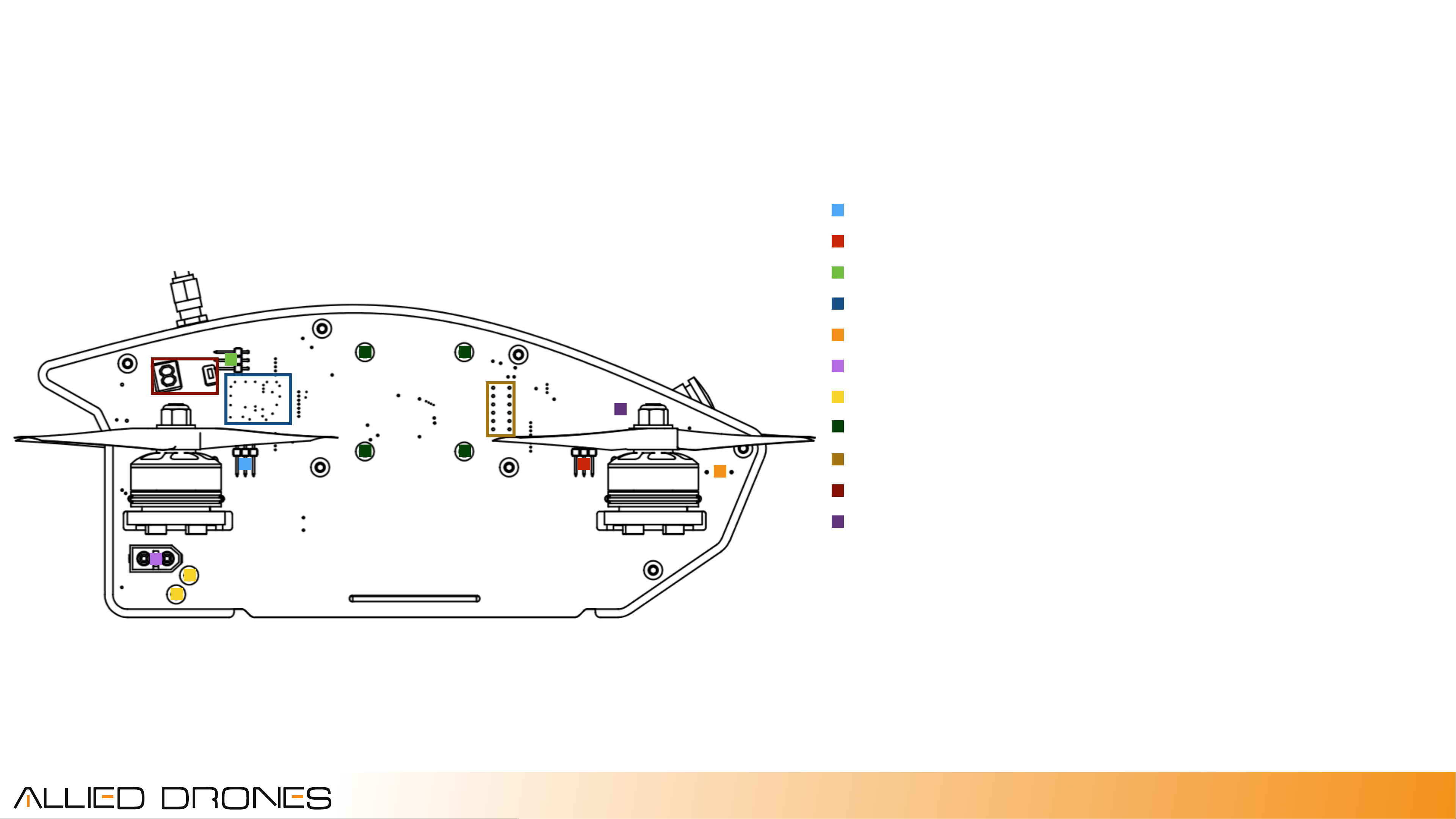
side plates
Right Plate (flight controller side)
Motor 1 ESC Signal Pins!
Motor 2 ESC Signal Pins!
5v Auxiliary Power Pins from BEC!
Filtered Auxiliary BEC (internal)!
Buzzer (internal)!
XT60 Main Battery Connector!
Gold Plated Bus Bar Screws!
Flight Controller Screws, black plastic!
OSD Advanced Solder Tabs and FTDI!
Video Transmitter Access Ports!
Video Camera Tilt Screws
12
rev 1 7/2016
Page 13
side plates
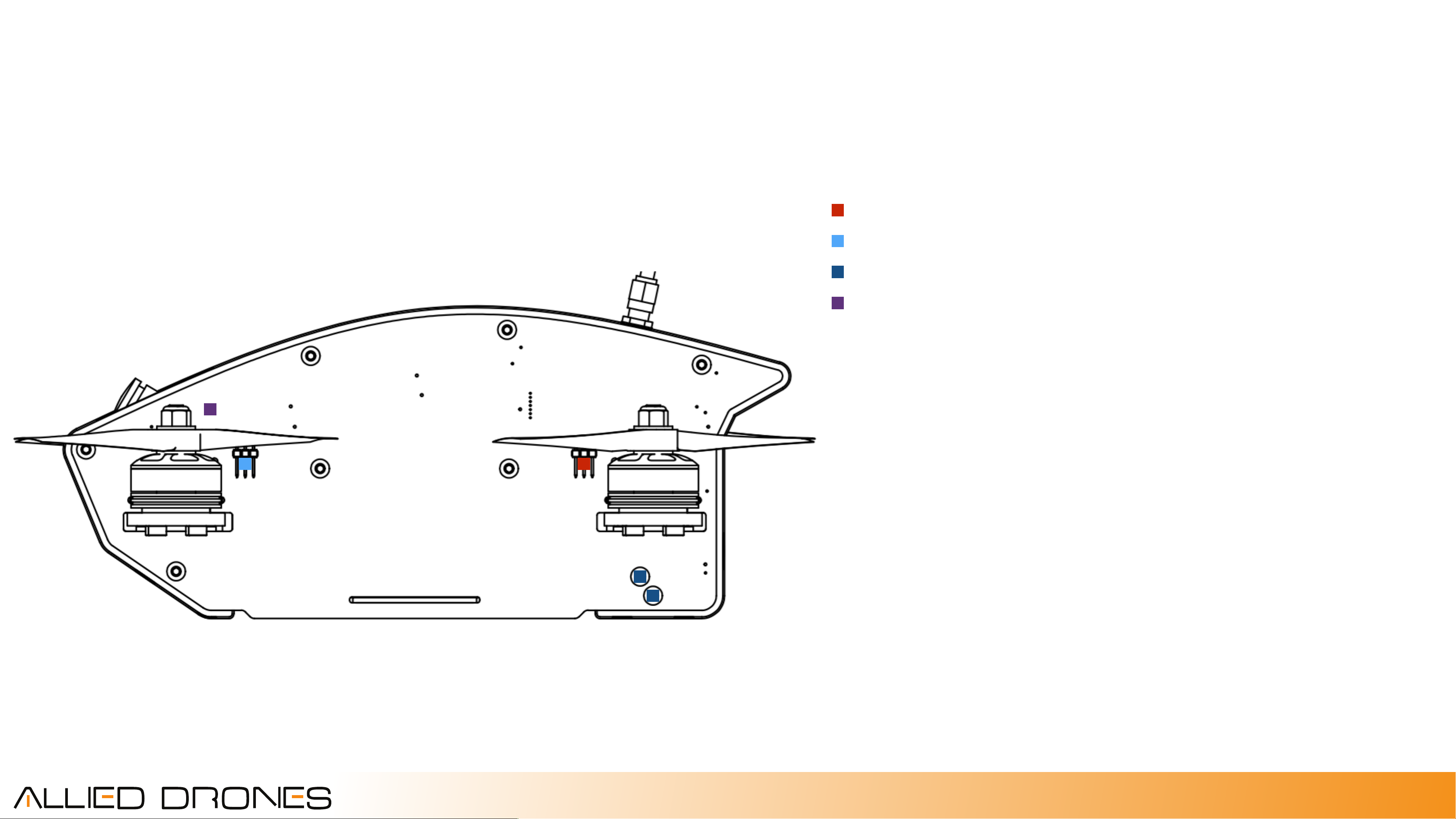
Left Plate
Motor 3 ESC Signal Pins!
Motor 4 ESC Signal Pins!
Gold Plated Bus Bar Screws!
Video Camera Tilt Screws
13
rev 1 7/2016
Page 14
side plates
LEDs
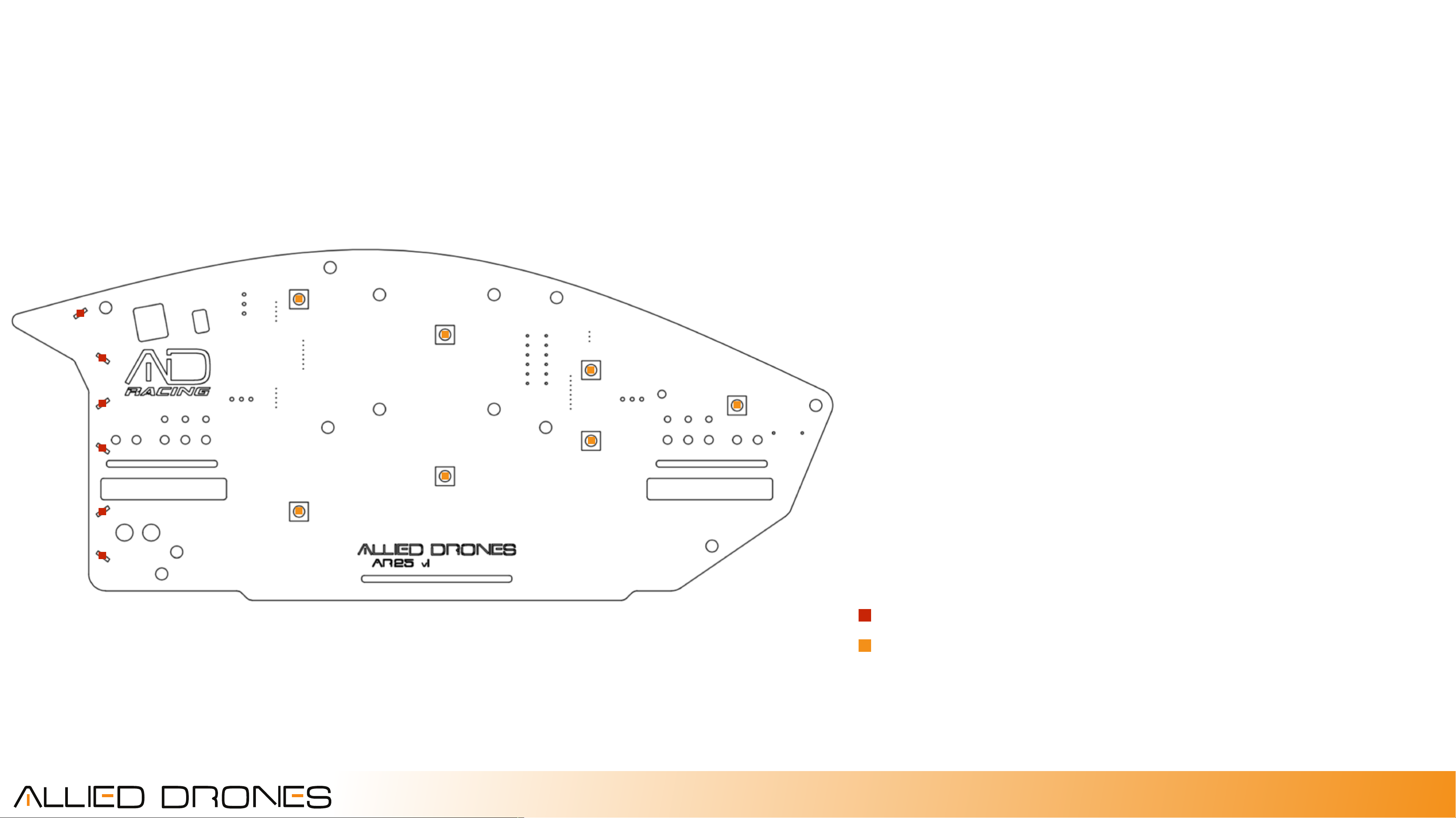
There are 7 programmable WS2812 RGB LEDs on
each of the AR25 side plates. These LEDs are able to
(0)
(1)
(2)
(4)
(3)
be programmed and controlled via the flight
controller and Betaflight firmware.
In addition to the 14 programmable LEDs, there are
also 12 non-programmable red LEDs facing the rear
of the AR25.
(6)
(5)
The address for each WS2812 programmable LED is
shown in the following diagrams.
Non-programmable solid red LEDs
Programmable WS2012 LEDs
14
rev 1 7/2016
Page 15
side plates
LEDs
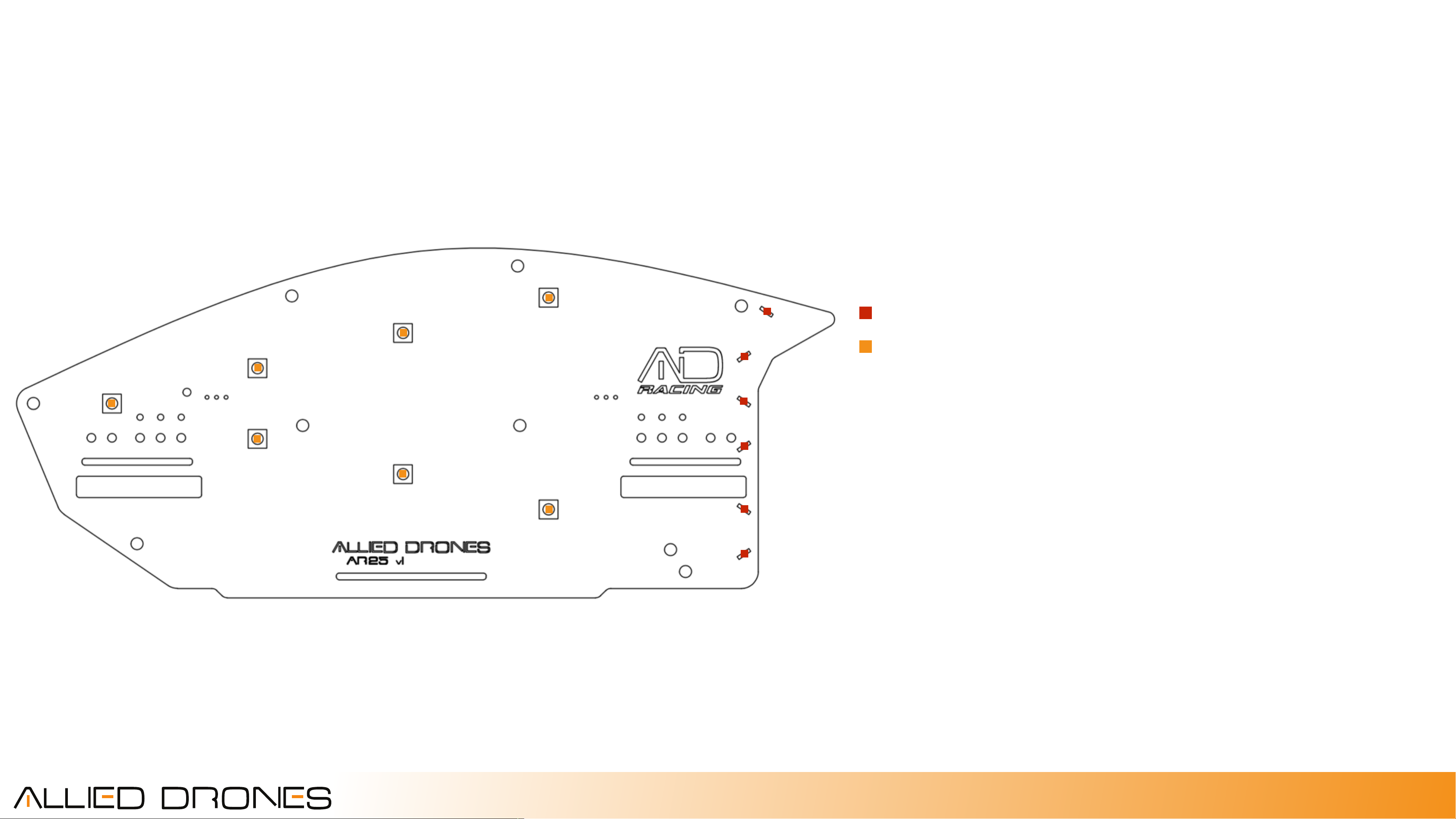
The address for each WS2812 programmable LED is
shown in the following diagrams.
(10)
(11)
(9)
(12)
(8)
(7)
Non-programmable solid red LEDs
Programmable WS2012 LEDs
(13)
15
rev 1 7/2016
Page 16
side plates
Bus Bar
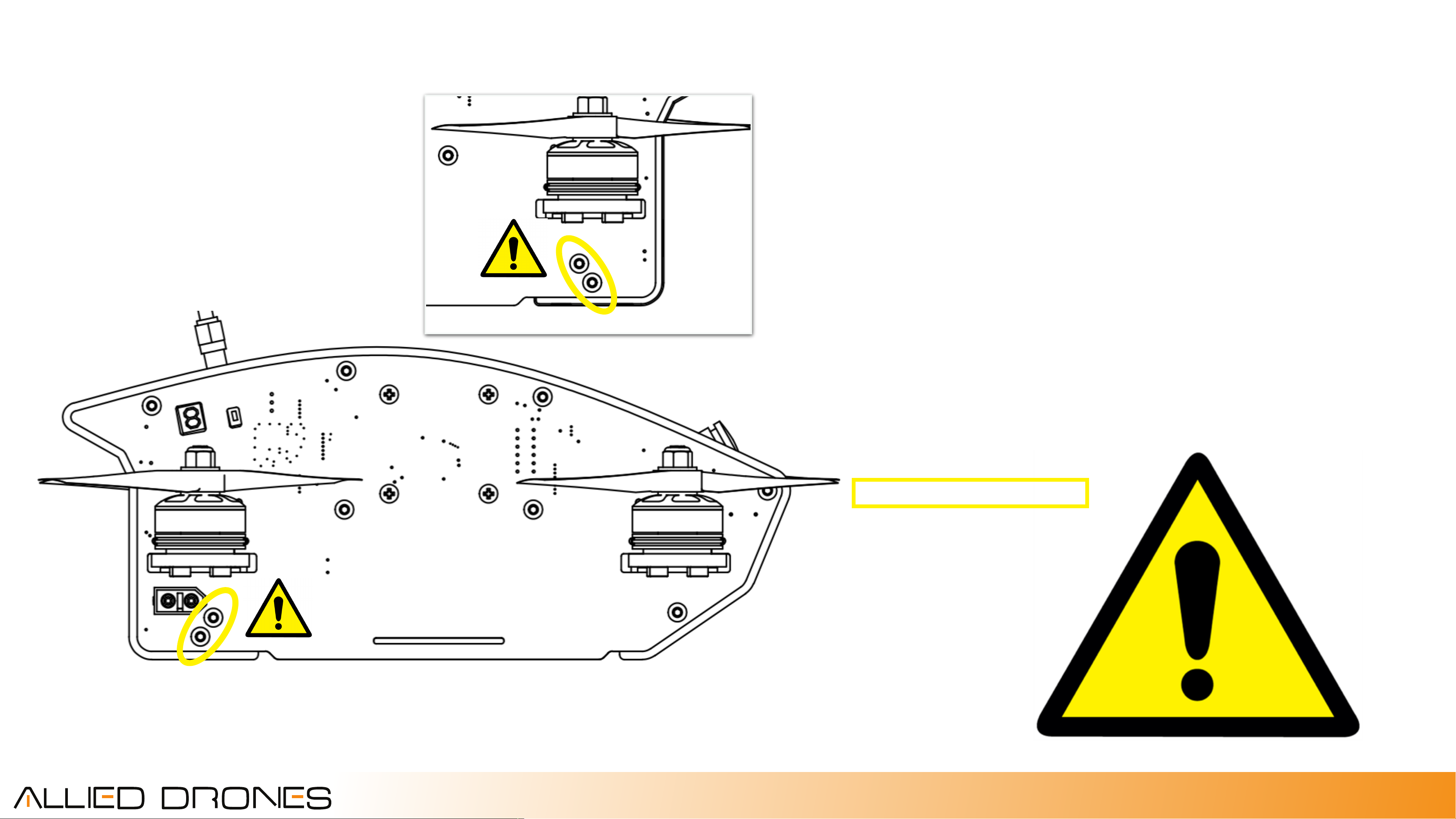
The two side plates of the AR25 have a pair of 24k
gold plated aluminum power bus bars connecting
them that supply power from the battery, through
the right side plate and then into the left side plate.
When the battery is connected no not short metal
tools across the gold plated bus bar screws.
Disconnect power first!
**check screw torque regularly**
16
rev 1 7/2016
Page 17
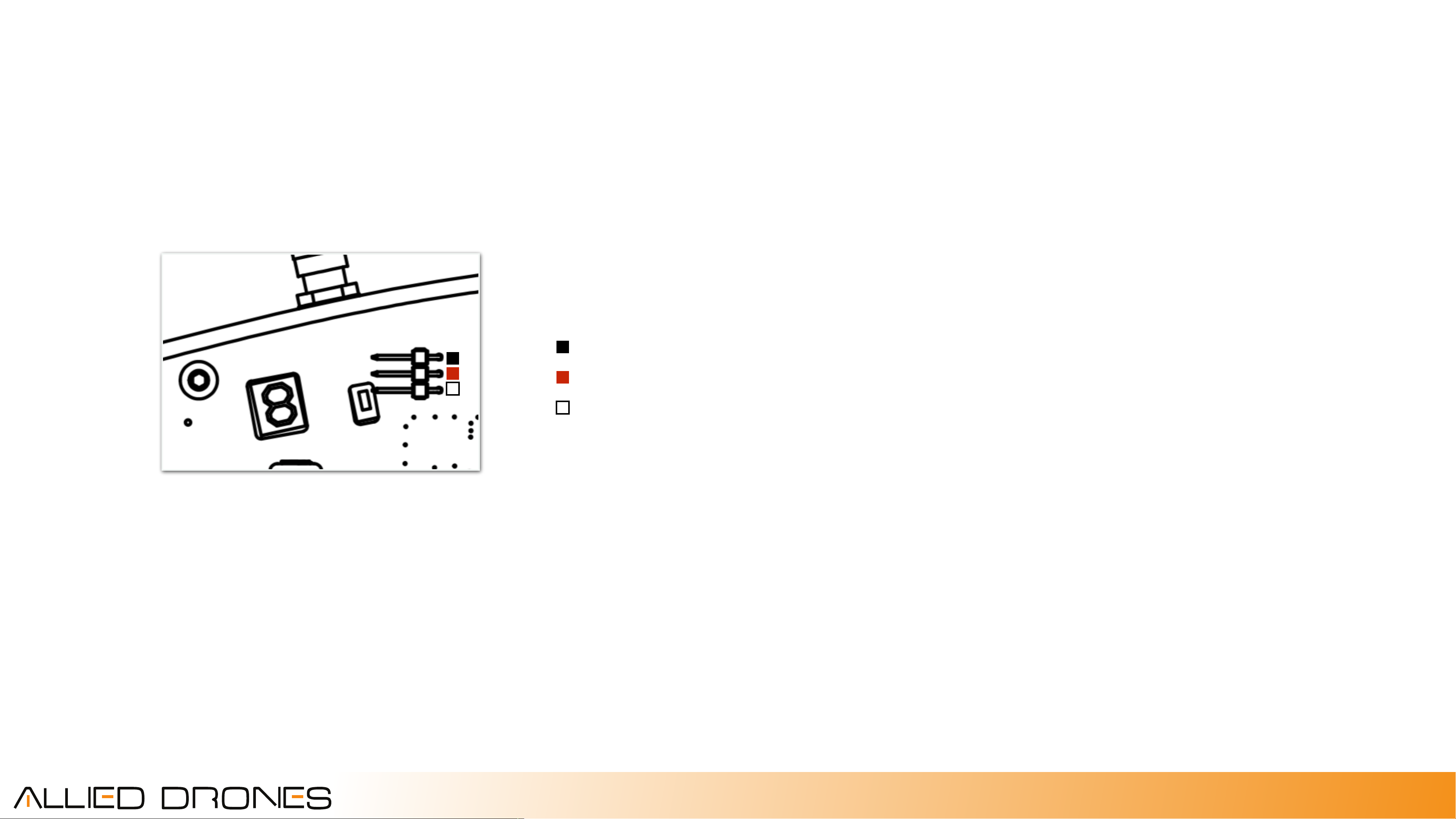
Auxiliary pins
An auxiliary 3-pin servo header has been provided
on the left side plate with a 5v center hot pin. This
Ground
+5v 3A
Signal (unused)
auxiliary pin receives regulated 5v power from the
integrated AR25 3A power supply and is intended to
allow for the easy addition of an optional LED race
transponder.
Compatible transponders are available from vendors
such as Trackmate and iLap, for instance. But please
check with your local racing venue to see which
system they use.
17
rev 1 7/2016
Page 18

battery
Specifications
Internal Battery Bay Dimensions: 111mm x 30mm x 35mm!
Standard AR25 battery: 4S 1P, 14.8v, 1800mAh, 60C, XT60, 210g!
Standard battery dimensions: 105mm x 27mm x 35mm!
Standard battery lead length: 150mm!
Charge Rate: 1-2C (max 5C)
The AR25 battery has been specifically designed for
the internal battery bay and features extended
battery discharge leads and a genuine XT60
connector to reach the power input on the left side
plate.
To insert the battery the battery leads must face to
the rear and bottom of the frame. First pass the XT60
connector through the slot to exit the rear of the
composite frame, then tuck the balance connector
into the slot. Tilt the rear of the battery into the bay
and then rotate the front of the battery into position.
Secure the battery by lightly separating the plates
while inserting and rotating the battery plate tabs
into the slots in the plates until it “snaps” into place.
18
rev 1 7/2016
Page 19
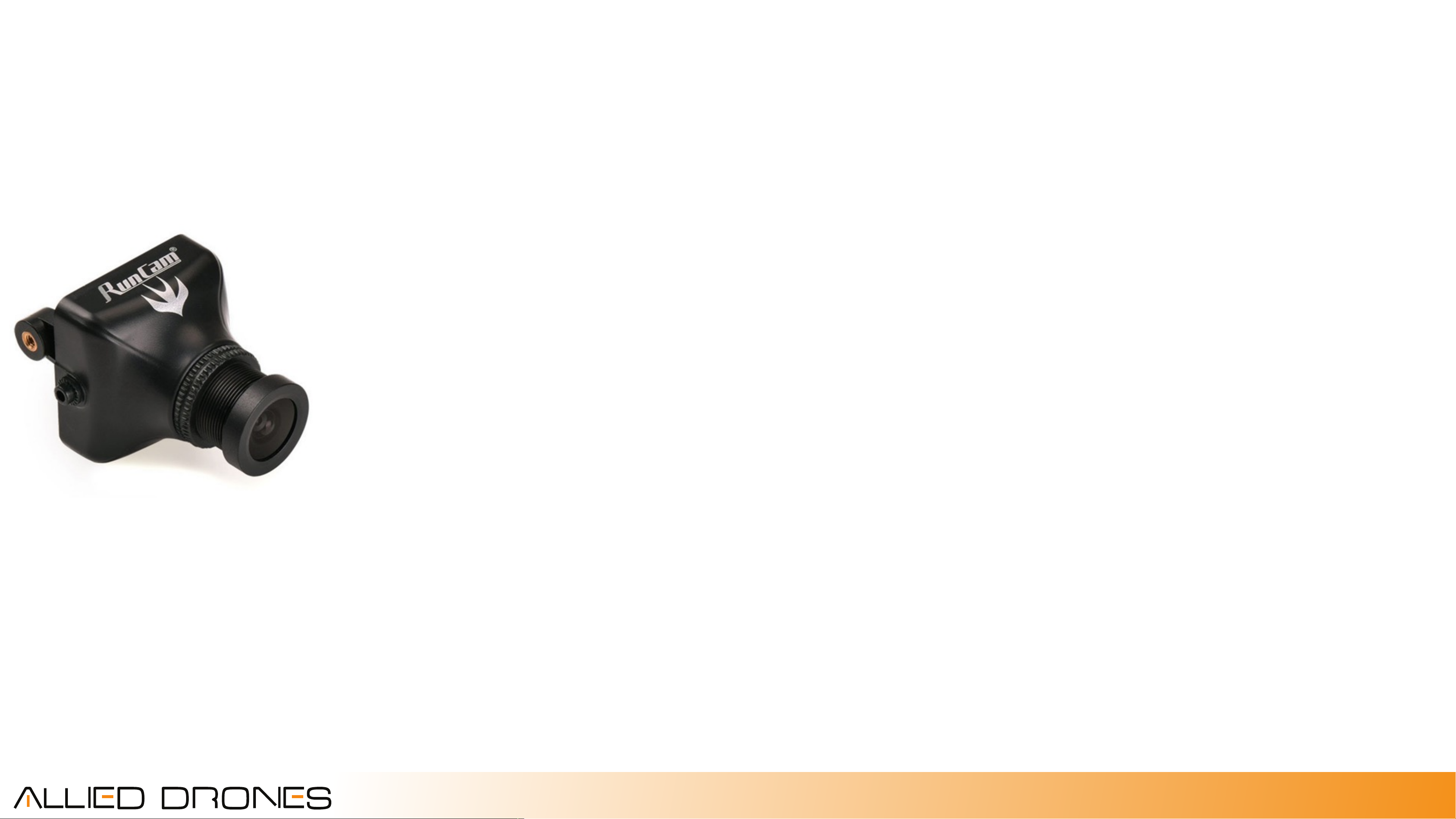
fpv system
Video Camera Specifications
Model!
The video camera installed in the AR25 is the best
RunCam Swift!
Image Sensor!
Horizontal Resolution!
Lens!
Signal System!
OSD Set!
S/N Ratio!
Electronic Shutter Speed!
Auto Gain Control (AGC)!
Back Light Compensation!
Minimum Illumination!
WDR!
1/3 Sony Super HAD II CCD!
600TVL!
2.8mm 90 fov!
PAL / NTSC!
Yes!
>60db (AGC off)!
NTSC: 1/60 ~100,000!
Yes!
Yes!
0.01 Lux/1.2F!
D-WDR!
available on the market. Battery voltage (4S,
12.8-16.8VDC) is supplied directly to the camera via
the side plate and 3-pin Molex connector. The video
signal passes through the MinimOSD and an
integrated LC Filter before reaching the Video
Transmitter.
DNR!
Day / Night!
Power!
Net Weight!
Dimensions
2DNR!
Auto/Color/B&W!
DC 5 to 17V!
12g!
26mm x 26mm x 28mm
2mm screws allow for easy camera angle
adjustments between 24° to 70°.
19
rev 1 7/2016
Page 20
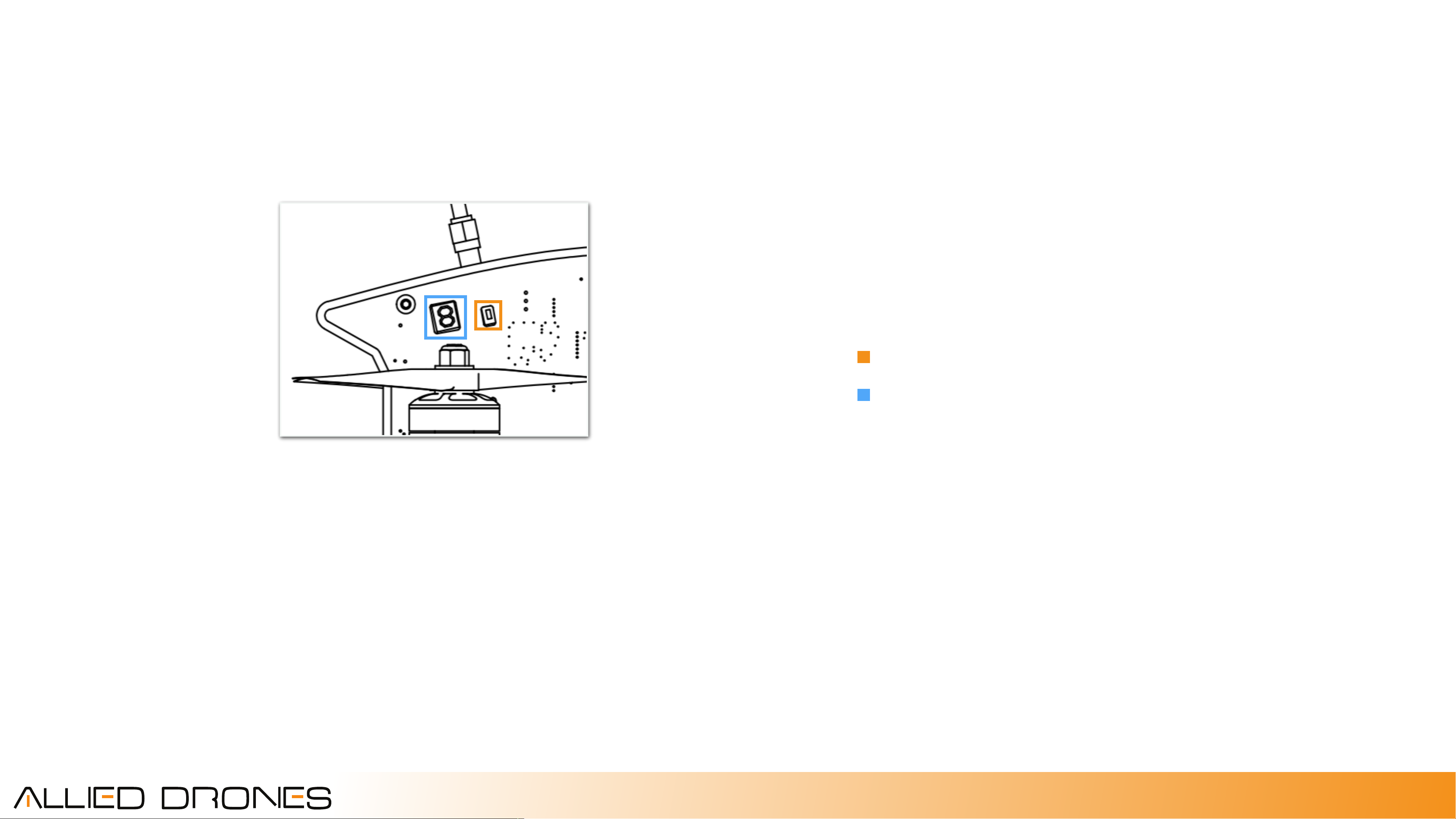
fpv system
Video Transmitter Specifications
The video transmitter channel display and change
button is accessible through two ports on the left
200mW!
CH1!
5865!
CH1!
5733!
CH1!
5705!
side plate. A short press will change channels while a
long press will change bands.
Button (short press - channel change, long press - band change)
Alternating Channel / Band Display
CH1!
5740!
CH1!
5658!
5.8GHz!
40 Channels!
Race Band!
SMA Connector
A
CH2!
CH3!
CH4!
CH5!
CH6!
CH7!
CH8
5845!
5825!
5805!
5785!
5765!
5745!
5725
B
CH2!
CH3!
CH4!
CH5!
CH6!
CH7!
CH8
5752!
5771!
5790!
5809!
5828!
5847!
5866
E
CH2!
CH3!
CH4!
CH5!
CH6!
CH7!
CH8
5685!
5665!
5645!
5885!
5905!
5925!
5945
F
CH2!
CH3!
CH4!
CH5!
CH6!
CH7!
CH8
5760!
5780!
5800!
5820!
5840!
5860!
5880
R
CH2!
CH3!
CH4!
CH5!
CH6!
CH7!
CH8
5695!
5732!
5769!
5806!
5843!
5880!
5917
20
rev 1 7/2016
Page 21
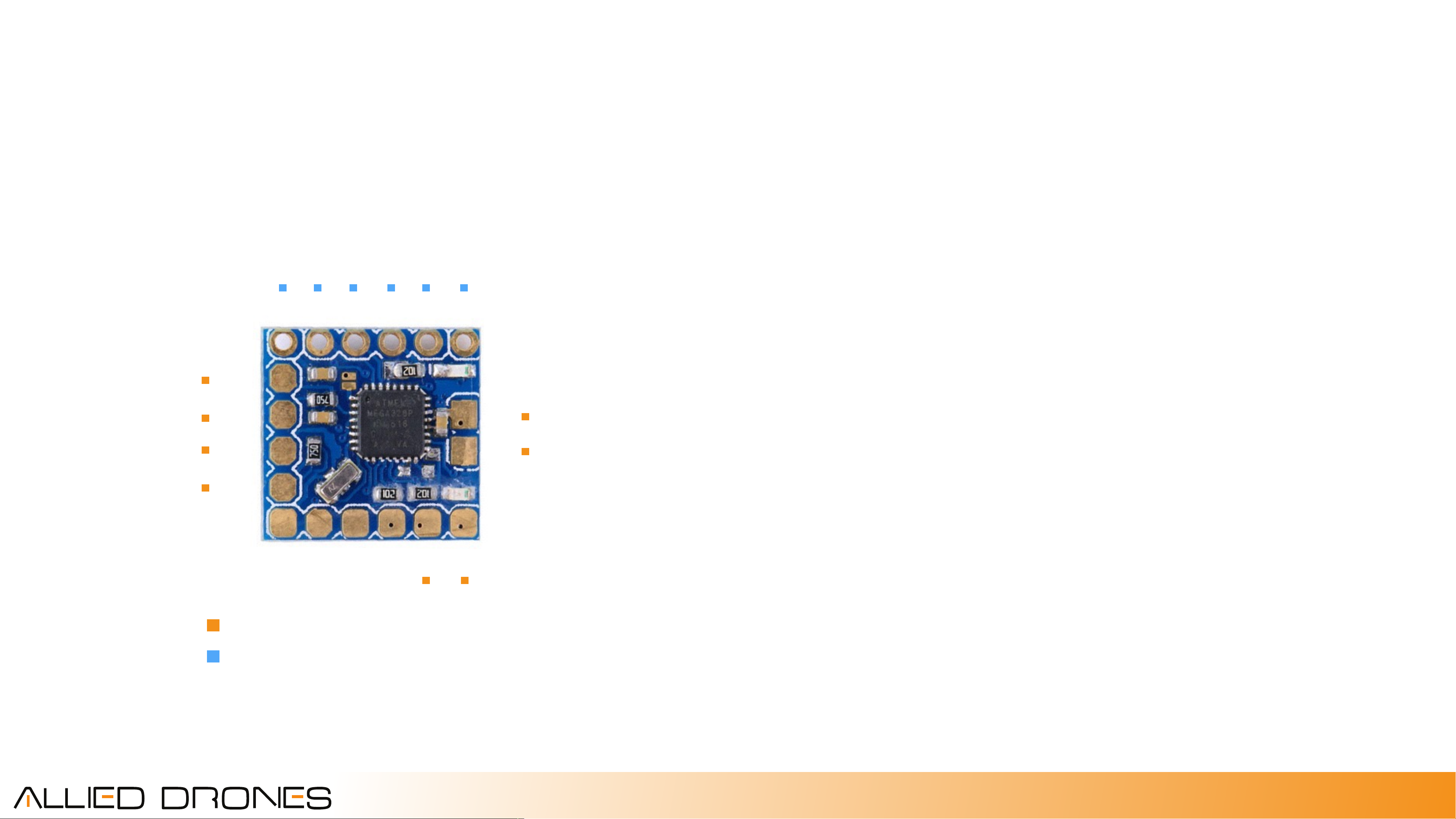
fpv system
On Screen Display (OSD)
The onboard video system of the AR25 features an
integrated OSD. The MinimOSD Micro with KV Team
GND
Vid In
GND
Vid Out
Mod was selected due to its small size and full
feature set. As delivered, the OSD has been flashed
DTR TX RX +5V GND GND
with MW OSD R1.6 and is programmed to display
battery voltage. Power is supplied by the
independent onboard 5v power supply.
GND
+5V
Additional advanced OSD features can be enabled
GND CURR RSSI Bat2 Bat1 GND
AR25 factory connections
Available pinouts via solder tabs (advanced users)
by expert users.
OSD video and voltage signal wires are integrated
into the 7-pin Molex connector on the side plate.
Additional pinouts for advanced users, including
FTDI, users are available via solder tabs on the side
plate.
21
rev 1 7/2016
Page 22

Accessories
Runcam HD Camera Mount
Carbon fiber bolt on isolated camera mount
GoPro HD Camera Mount
Carbon fiber bolt on isolated camera mount
FPV Camera Up Armor Kit
Carbon fiber armor kit for increased crash protection
Custom 6” Prop Booms
Carbon Fiber, 4mm, suitable for 6” Props
22
rev 1 7/2016
Page 23

Specifications
Weight RTF w/o battery: 556g!
Length, Width, Height: 223.5mm x 218.6mm x 96.9mm!
Motor Diameter / MultiGP Class: 239mm / 3S, 4S, Open!
Propellers: 2- or 3-blade DALProp 5045 bull nose!
Motors: Allied Drones 2205 Special Edition 2300kv hollow-shaft race motors!
Battery: 4S 1800mah 75C!
ESC: Flycolor Raptor 30A!
FPV Camera - Runcam Swift!
Flight Controller: RMRC Dodo rev. 3a, Betaflight!
OSD: Micro MinimOSD w/ KV team mod, MWOSD firmware!
FPV Tx:!5.8G 200mw 40CH Super Mini, Race Band, SMA antenna connector!
Antenna: SMA!Circular Polarized Omni Directional!
LEDs: 14 integrated WS2012 programmable RGB + 12 solid red rear facing LEDs!
RC Rx - integrated connector Frsky XSR micro sbus receiver!
Race Transponder: External auxiliary 3-pin 5V connector compatible with any optional LED transponder!
Airframe: ABS/Polycarbonate composite core with FR4 power/signal distribution plates!
Side Plates: Integrated 3A 5V filtered power regulator, 26 LEDs, 4mm carbon fiber booms, internal battery bay, XT60 surface mount power connector, 24k gold
plated contacts edge plating and logos, white solder mask, individually accessible ESCs and motor wires, 24k gold plated side plate power bus bar and screws,
integrated LC video filter, integrated ESC filters!
Buzzer: Integrated lost model buzzer
23
rev 1 7/2016
Page 24
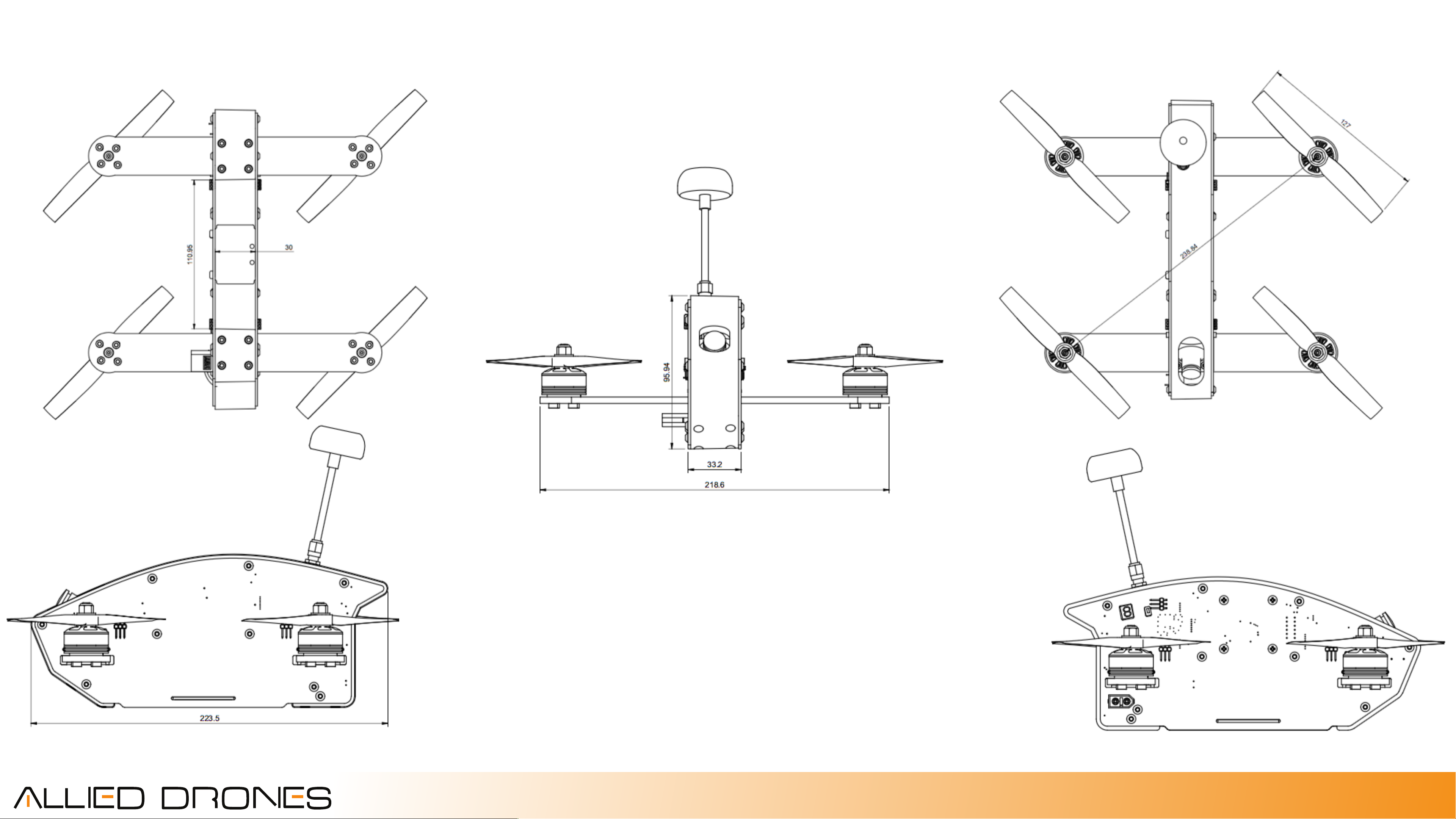
Specifications
24
rev 1 7/2016
 Loading...