

Page 1

V-SERIES™ APPLICATION GUIDE
ARCHITECTS • ENGINEERS • BUILDERS
Page 2

Page 3

TABLE OF CONTENTS
1. PURPOSE OF THIS MANUAL
2. MAGIC-PAK: DESIGNED AND BUILT FOR EVERY
STAGE OF DEVELOPMENT
2.1 TOTALLY PACKAGED HVAC SYSTEM PROVIDES
INDIVIDUAL COMFORT CONTROL
2.2 SLIDE-OUT COOLING CHASSIS
2.3 HERMETICALLY SEALED REFRIGERATION SYSTEM
2.4 INTERCHANGEABLE WITH EARLIER MODELS
2.5 GAS AND ELECTRIC ALTERNATIVES
8. OUTSIDE DECORATIVE FACADES, GRILLES OR
LOUVERS
8.1 GRILLE AND LOUVER FURNISHED ON MAGIC-PAK
8.2 OUTSIDE APPEARANCE VARIATIONS
8.3 CONSIDERATIONS FOR CUSTOM LOUVERS
8.4 CONTROL OF SOUND WITH LOUVERED GRILLES
9. CONDENSATE
9.1 CONDENSATE DRAIN
9.2 HIGH EFFICIENCY UNITS
3. UNIT LOCATION
3.1 GENERAL CONSIDERATIONS
3.2 SOUND CONSIDERATIONS
3.3 ACCESSIBILITY
3.4 VENT LOCATION FOR GAS MODELS
4. WALL SLEEVES
4.1 INSTALLATION
4.2 RECESSED SLEEVES
4.3 WEATHER-PROOFING WALL SLEEVES
5. TYPES OF WALL CONSTRUCTION
5.1 SUPPORT
5.2 WOOD-FRAME WALLS
5.3 CEMENT BLOCK WALLS
5.4 POURED CONCRETE WALLS
5.5 METAL STUDS
6. NOISE TRANSMISSION
6.1 VIBRATION TRANSMISSION
6.2 RADIATED SOUND AND RESONANT SURFACES
OR OBJECTS
6.3 CLEARANCES
6.4 DETERMINATION OF SOUND RATING VALUES
6.5 AIR NOISE
6.5.1. SUPPLY-AIR DUCT SYSTEM
6.5.2. RETURN-AIR DUCT SYSTEM
10. ELECTRICAL SERVICE WIRING
11. AIR FILTER
12. SPECIAL CONSIDERATION FOR GAS UNITS
NOTES
7. INFILTRATION
7.1 WATER INFILTRATION
7.2 AIR INFILTRATION
7.3 INTRODUCTION OF VENTILATION AIR
7.4 SEALING RETURN-AIR DUCTS
7.5 SEALING WALL SLEEVE
3 | V-SERIES™ APPLICATION GUIDE
Page 4

For over 50 years, the
Magic-Pak concept of providing
heating and cooling in high-rise
condominiums and apartment
buildings has proven increasingly
popular among building designers
and mechanical contractors.
1. PURPOSE OF THIS MANUAL
This manual provides assistance to architects and design engineers who are considering the use
of Magic-Pak heating and cooling equipment in multi-dwelling buildings.
This document conveys some of the experience gained over many decades, and includes some
of the most successful and economical installation practices for Magic-Pak units.
Building structure heat loss and heat gain, duct sizing, gas supply mains and riser sizing, and
electrical-supply wiring should be determined for the building by a qualied Professional
Engineer familiar with the applicable local building code requirements for the type of occupancy.
2. MAGIC-PAK: DESIGNED AND BUILT FOR
DESIGNERS AND BUILDERS
2.1 TOTALLY PACKAGED HVAC SYSTEM PROVIDES INDIVIDUAL COMFORT CONTROL
The Magic-Pak concept provides all the practical benets of a split system, plus a heating
system, without the expense and complications of split-system units. Magic-Pak provides a
ducted, single-package, combination heating-and-cooling unit for each individual suite that
is reliable, easy to install and inexpensive to maintain. Just as important, it allows individual
metering and control for each unit.
Over these years with literally
hundreds of thousands of units
installed throughout the United
States and Canada, we have
compiled comprehensive practical
experience for varying types of
building construction and operating
conditions.
Occupants can have heating or air conditioning any time of the year according to the outdoor
temperature. A cold day in June, heating; a hot day in January, cooling. This is exibility you may
not get from some central systems.
2.2 SLIDE-OUT COOLING CHASSIS
The slide-out cooling chassis is unique to Magic-Pak units and is a chief contributor to the
ever-increasing popularity of the product. If service is required, any cooling chassis may be
replaced with another in minutes. In fact, building maintenance personnel can easily perform
this function without the refrigeration training or trade credentials often required to work on
refrigeration systems.
2.3 HERMETICALLY SEALED REFRIGERATION SYSTEM
The hermetically sealed refrigeration system is another feature of the Magic-Pak’s slide out
refrigeration chassis. The system is completely factory-built, checked for leaks with sensitive
electronic equipment, and thoroughly performance tested before placement in any unit. This
comprehensive testing eliminates the need for highly trained personnel at the time of installation
or start up.
2.4 INTERCHANGEABLE WITH EARLIER MODELS
Another advantage of the slide-out chassis is the one that eliminates concerns of obsolescence.
Replacement chassis are only available for units going back to 3rd version units. The chassis
built today include modern techno logy in heat transfer surface and compressor design for higher
efciencies, but the chassis will still t the older Magic-Pak models. For more information,
contact application specialist.
4 | V-SERIES™ APPLICATION GUIDE
Dedication to this interchangeability with earlier models is basic to the Magic-Pak concept of
today and insures that these units will never become “orphans” in the future.
Page 5
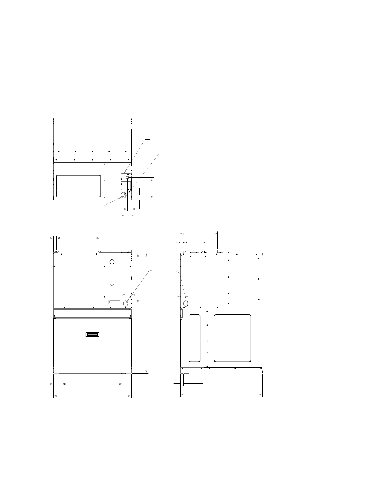
2.5 GAS AND ELECTRIC ALTERNATIVES
22
27-7/8
29
7
/
16
13-3/8
43-3/16
18
2
7
/
8
161
61
81
2 3/4
1-3/4
8
2
Supply
Supply
Return
Return
1/2 Gas Inlet
Low
Voltage
Line Voltage
Box
Supply
11/
2
Condensate
Drain
HWC9
Only
1
/
4
2
Magic-Pak offers a variety of heat sources to best suit the geographic area or local energy costs.
All are ducted, through-the -wall units which have no need for chimney/vent pipe.
HWC -Gas Heating, Electric Cooling:
Depending on energy cost in your area, gas heating could maximize applications where gas
is available. Magic-Pak is classied as a direct vent application which uses only outside air for
combustion. This allows the built-in power vent to eliminate the need for a chimney.
Fig 1. HWC V-Series Model
5 | V-SERIES™ APPLICATION GUIDE
Page 6
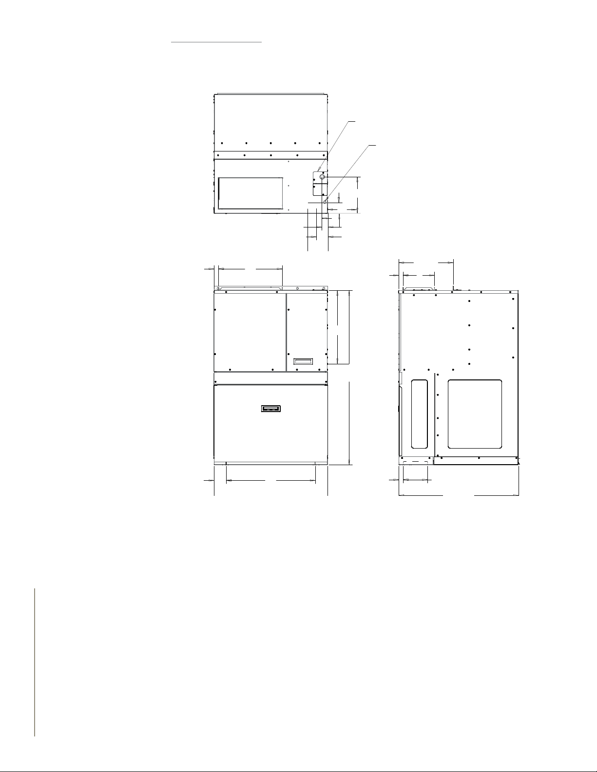
EWC - Electric Heating
7
Electric heating and cooling is an alternative solution when gas is not available, or in milder
geographies.
Line Voltage
Box
Low
Voltage
1-3/4
Supply
11/
2 3/4
2
8
27/
8
1
161
Supply
1
/
4
18
43-3/16
Return
7
8
/
2
22
13-3/8
81
61
Fig 2. EWC V-Series Model
6 | V-SERIES™ APPLICATION GUIDE
Page 7
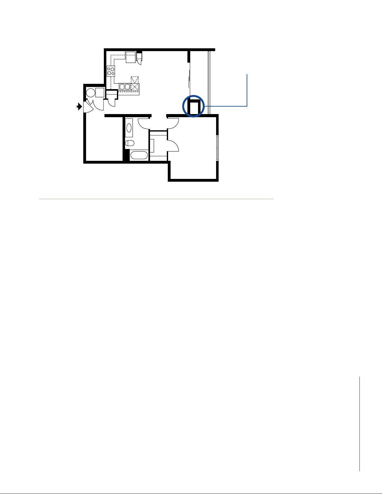
3. UNIT LOCATION
MAGIC-PAK
Figure 3. Condominium with Magic-Pak on exterior wall
3.1 GENERAL CONSIDERATIONS
A building wall should be no closer to an opposite building wall than two feet for every oor or
Magic-Pak unit in a vertical array facing the wall. For example, a one-story building with a Magic-
Pak unit should be a minimum of 2 ft. from the wall facing the unit, and if the facing wall also
has a Magic-Pak unit, the two walls should be at least 4 ft. apart.
Magic-Pak units should be installed
in an exterior building wall that
is clear of obstructions which
might impede the free intake and
discharge of condenser air.
A six-story building with six Magic-Pak units in a vertical array should be at least 12 ft. from
the opposite building wall, and if that building wall also contains Magic-Pak units, the buildings
should be at least 24 ft. apart.
Buildings taller than six stories need not exceed the separation needed for six-story buildings.
If three or more adjacent walls form an air shaft with Magic-Pak units facing each other in each
wall, the separation between opposite walls should be increased by 20%.
These “rules-of-thumb” dimensions are intended to minimize possibilities for recirculation of
condenser air, or interaction between units. However, these numbers are not exact for every
application, and other considerations might suggest that the designer consult the application
specialist about desired alternatives. In colder climates, the location of a unit should be
considered due to possible frost back-up.
Buildings that are designed with the utility closet next to each other, or stacked, need to have
a minimum horizontal clearance of 12” between units and a vertical clearance of 60” between
units (see Fig. 4).
7 | V-SERIES™ APPLICATION GUIDE
Page 8
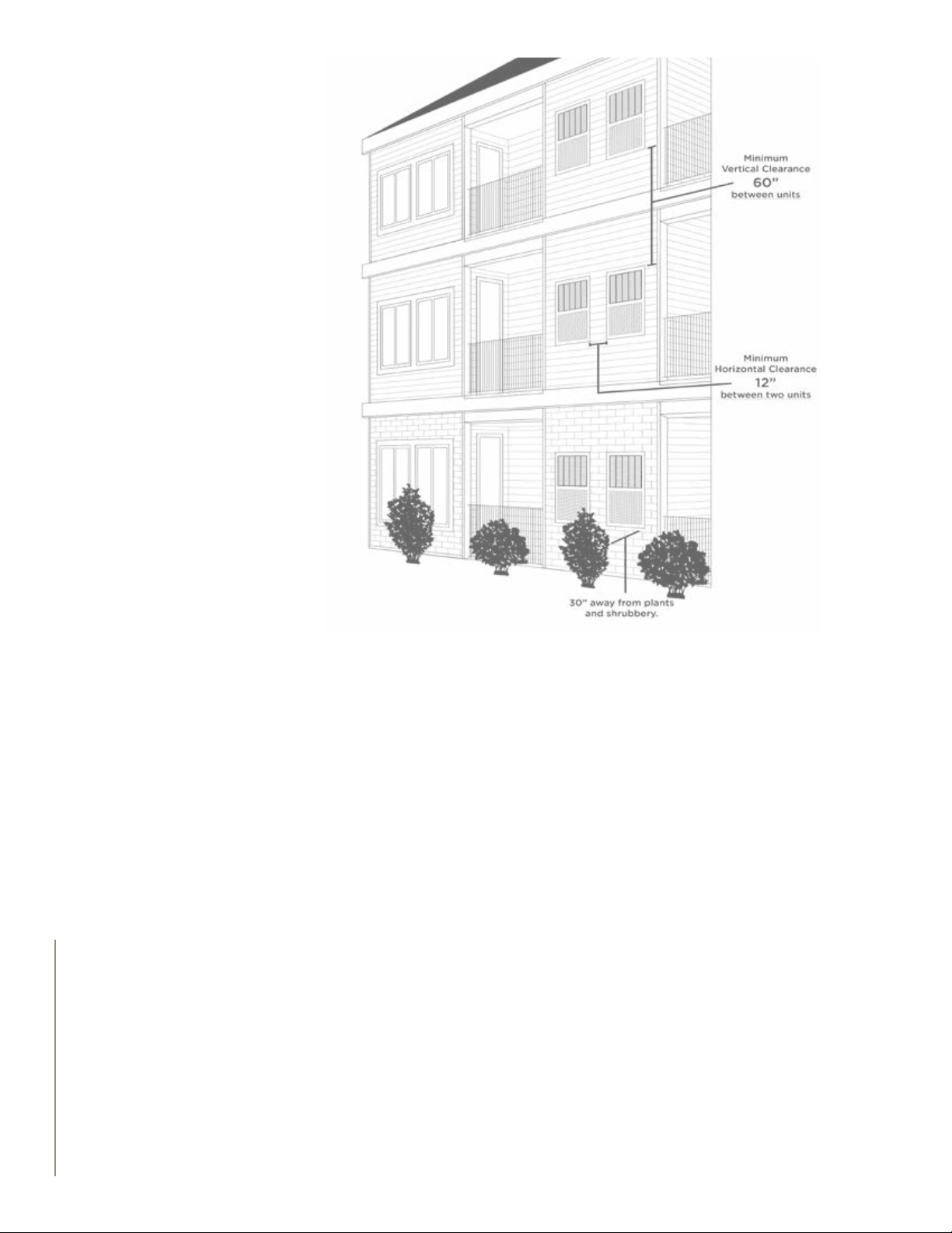
Fig 4: Building Clearance Needed
3.2 SOUND CONSIDERATIONS
It should be mentioned that any time a hard surface or wall faces a unit, the sound emanating
from that unit can be reected by the opposite wall. If the two walls are not parallel, the sound
may be somewhat dispersed, but in general it is preferable to locate Magic-Pak units in a wall
with as much clear distance to the nearest wall or reecting surface as is practical.
Units located in walls forming an air shaft or conned courtyard are not as desirable (from a
sound standpoint) as units located in the outer perimeter walls of a building.
Similarly, if the unit is to be installed in a wall at right angles to a wall containing a window, at
least 6 ft. of separation be tween the closest point of glass to the unit should be maintained in
order to minimize sound transmission through the window.
If, however, such a location is unavoidable contact the application specialist. For suggestions on
how others have succeeded in overcoming the challenges.
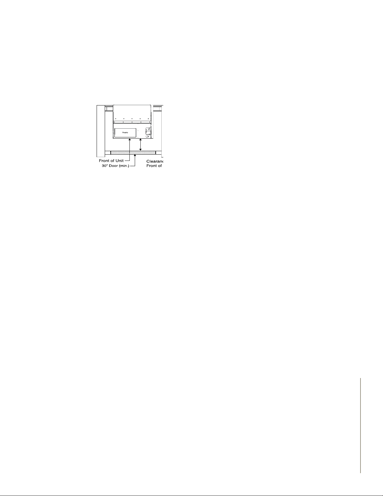
3.3 ACCESSIBILITY
An important consideration when selecting a suitable location is accessibility for chassis removal.
A 30 in. wide minimum clear opening is needed in front of the unit in order to remove the
chassis. A 36 in. wide door or access covering to the enclosure is preferred as a minimum to
allow for some tolerance in locating the access door frame exactly centered on the unit ( Fig 5).
8 | V-SERIES™ APPLICATION GUIDE
Page 9
If the unit is located in the end of a clothes closet, and it is accepted that the clothes must
be removed rst to remove the chassis, be sure that the closet door is large enough to get the
chassis out of the closet.
Also, if the Magic-Pak is installed through the side of a closet, be sure the closet is wide enough
to permit sliding the chassis all the way out before running into the opposite closet wall.
Fig 5: clearance needed for Chassis.
(Note: There are special dollies available through wholesalers that can lean the platform from
vertical to horizontal with an elevating-adjustment feature and four wheel support. These are
very useful in close quarters to provide a platform to slide the chassis onto during removal and
subsequent replacement of a chassis.)
Units in a relatively inaccessible location for easy chassis removal should be avoided if at all
possible; if for no other reason than to keep the air lter accessible for easy and timely cleaning
by the occupants or by maintenance personnel.
3.4 VENT LOCATION FOR GAS MODELS
Vent location of gas-red Magic-Pak models must comply with the latest edition of the National
Fuel Gas Code (NFPA 54/ANSI Z223.1), and local codes.
The design is certied for indoor installation only. The interior portions of the unit may be
surrounded by a closet with minimum clearances to combustible material held to 0” sides, 2”
top, and 1” front and plenum. Adequate clearance must be provided to install gas line union and
manual shutoff valve as well as providing accessibility for eld wiring. Do not install directly on
carpeting, tile, or other combustible material other than wood ooring. The grille side of the
unit may be ush with, or extend beyond, the face of exterior wall, but should not be recessed
more than 2” from the face of the building and should not be obstructed with trees, landscape
materials, or building structure (see Fig. 4). There is no minimum clearance required on locating
the unit to an interior corner of a building.
9 | V-SERIES™ APPLICATION GUIDE
Page 10
“Wall sleeve” is an accessory for the
Magic-Pak units. The wall sleeve is
designed to facilitate the installation
of Magic-Pak units by providing an
accurate opening during building
construction. Units can then remain
o-site until building construction
approaches completion.
4. WALL SLEEVES
Wall Sleeve
0” X 22” Minimum
opening to Align
with return air
opening in unit
2
16
45
2
Plywood
(bottom layer)
29
Flanges may be assembled
3/4
1” or 3
” from front of sleeve
Vibration Isolating Material
(Top Layer)
1/2
12
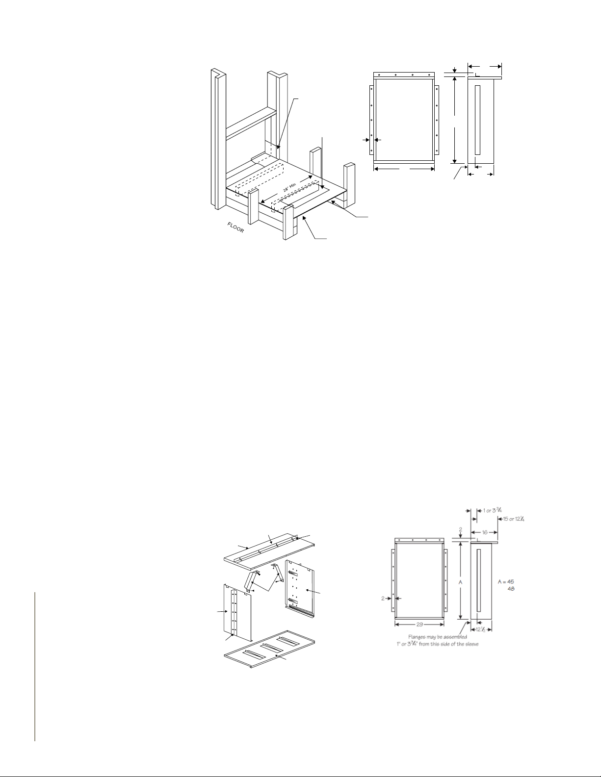
Fig 6: Wall sleeve frame
The wall sleeve is comprised of four assemblies (top, bottom, and right and left sides see g 7).
These easily slip together on the job to form a rectangular box correctly sized to receive a Magic-
Pak unit. When in place and securely fastened, the wall sleeve opening provides easy access to
the nished wall perimeter for caulk sealing.
Magic-pak recommend that a wall sleeve be fastened into the wall opening and caulk sealed
around the outside perimeter at the building wall. In multi-story buildings, weather sealing may
be done by access through the opening in the wall sleeve later to be lled by the Magic-Pak unit.
10 | V-SERIES™ APPLICATION GUIDE
The weather-seal caulking is easier to perform when the sleeve protrudes beyond the nished
wall by 3/8 in. to 1 in.
Right Side Panel
Side support angle
Front of
Sleeve
Top Panel
Squaring
Braces
Top Support Angle
Left Side Panel
Bottom Panel
Fig 7: Wall sleeve assembly Fig 8:Wall sleeve dimensions
Page 11
4.1 INSTALLATION
The sleeve may extend farther than 1 in. beyond the nished wall, but reaching the perimeter of
the opening from inside for sealing becomes increasingly difcult (Figs. 9 & 10)
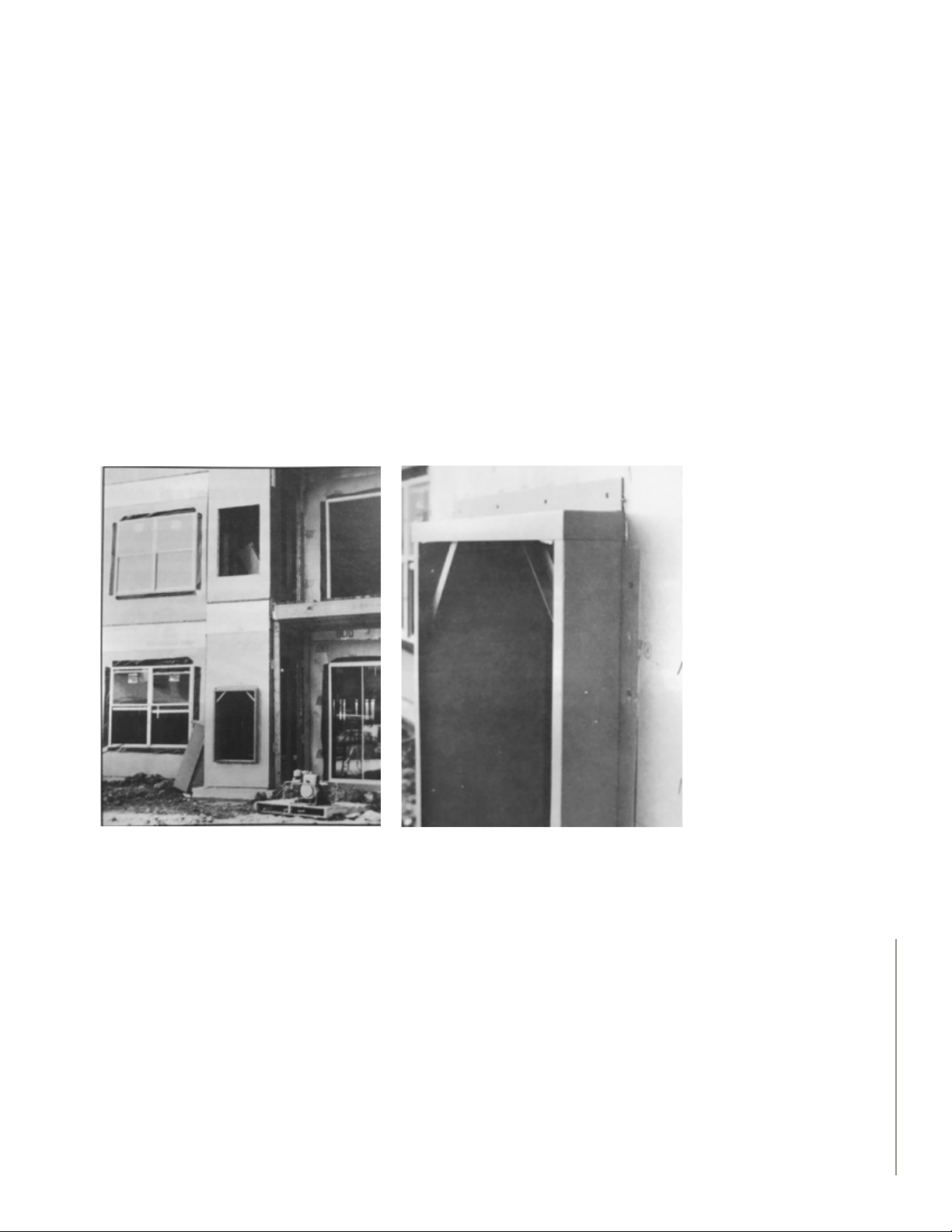
In many high-rise construction applications, contractors insert the wall sleeves from the outside
while the wall is being constructed (Fig. 11, 12, 13). The two-sided support angles furnished with
the wall-sleeve kit should then be attached to the wall sleeve sides at a location that will exceed
the thickness of the outside nish wall by the recommended 3/8 in. to 1 in. dimension. Support
angles should not be considered ashing.
For example, if the supporting wall is concrete block with a brick facing, there is usually a space
between the block and the brick. This space dimension must be added to the width of the brick
(plus 3/8 in. to 1 in.) so that when the sleeve is inserted into the block-wall opening, up to the
angles, and fastened to the block wall before the brick is installed, the sleeve will protrude beyond
the nished brick by 3/8 in. to 1 in., as needed for caulk sealing.
The wall sleeve must be fastened to the supporting wall and not to the nished wall.
Figure 9: Wall sleeve installed from outside
angle 1
Figure 10: Wall sleeve from outside angle 2
11 | V-SERIES™ APPLICATION GUIDE
Page 12
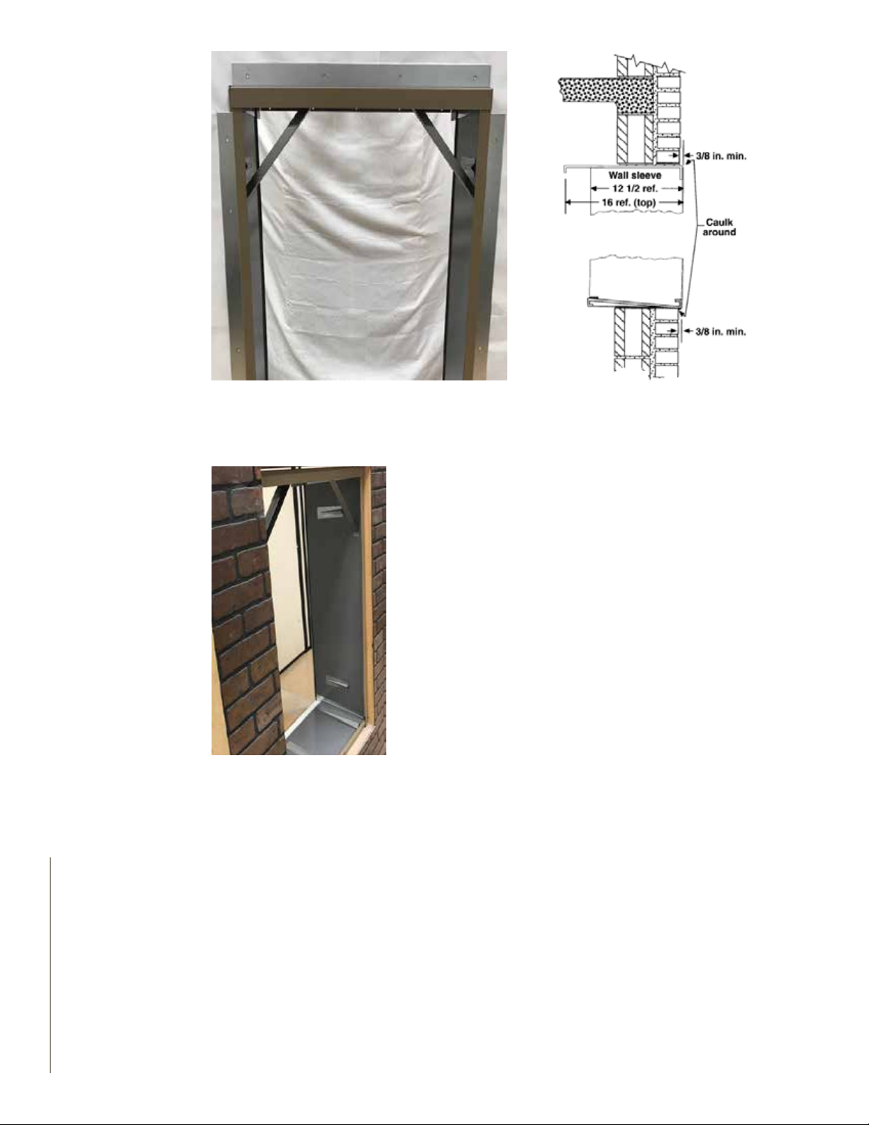
Figure 11 - Wall sleeve installed from outside
angle 3
Some builders will attach through the side support angles
to the support wall whether inserting the sleeve from the
outside or inside. Others will use the side angles simply as a
locating “stop” to achieve the appropriate dimension while
shooting fasteners through the sides of the wall sleeve into
the supporting wall (See Fig. 13).
The most popular method of installing the wall sleeve is from
the inside of the building with the weather seal applied from
the outside as the nish wall is applied (See Fig. 19).
Figure 13 - Fasteners shot
through wall sleeve sides into
back wall
Figure 12 - Caulk around sleeve
12 | V-SERIES™ APPLICATION GUIDE
Page 13

4.2 RECESSED SLEEVES
In some applications, where building walls are very thick (over 16 in.) or architectural design
dictates, units can be recessed. One should avoid recessing the wall sleeve if the wall opening is
required to be the same as the wall-sleeve opening. However, if the wall opening can be larger in
vertical dimension than the wall sleeve, so that the bottom can rest on a sill that is at least 2 in.
higher than the bottom of the wall opening, some recessing is permitted (Figs. 13 and 14).
This sill should be recessed further than the sleeve by 3/8 in. to 1 in. to permit weather-seal
caulking along the bottom edge without plugging the drain holes in the sleeve. See Fig. 15.
The top of the wall opening should be above the top of the wall sleeve by a dimension equal to or
greater than the amount of the recess to avoid restriction of the condenser discharge air.
Figure 14: Recessed wall sleeve with enlarged
and tapered-edge opening.
Figure 15: Recessed wall sleeve with enlarged
and tapered-edge opening.
13 | V-SERIES™ APPLICATION GUIDE
Page 14

Figure 17 - Caulk seal outside joints
of wall sleeve before inserting into
wall opening (Underside view of
wall sleeve bottom).
Figure 16 - For additional protection against air inltration
during periods of very high winds, ll the clearance space
between unit and wall sleeve all around with sealant.
4.3 WEATHER-PROOFING WALL SLEEVES
Figure 18 - Caulk seal outside joints
of wall sleeve before inserting into
wall opening.
Wall sleeves are packaged one to a carton and are shipped at. They snap together easily at the job
site and are held square (until ready to receive a Magic-Pak) by two braces fastened inside the top
corners. Instructions for caulk sealing the slip joints and spot-welded joints are included.
This sealing must be done after the wall sleeve is assembled, but before the Magic -Pak unit is
installed in the sleeve. Caulk sealing of the bottom is best accomplished right after the wall sleeve
is assembled but before it is placed in the wall opening (Fig. 17). Remaining nal sealing can be
done just after the sleeve is secured into the wall opening, if desired, to avoid breaking the seal
during handling (Fig. 19).
Further sealing against air inltration must be done after the Magic-Pak unit is installed in the wall
sleeve and utility connections are completed. For additional protection, the space between the unit
and the wall sleeve should be sealed on all sides with a bead of sealant.
14 | V-SERIES™ APPLICATION GUIDE
Page 15

5. TYPES OF WALL CONSTRUCTION
5.1 SUPPORT
In general, a wall sleeves will support a Magic-Pak units on any wall. The wall, however, must be
adequate to support the unit. Otherwise, one must provide additional support between the unit
and the oor. The center of gravity is between the bottom return-air opening rear ange and
the wall sleeve. When additional support for the unit is desirable, it should be near this center of
gravity and applied evenly across the bottom of the unit through adjustable legs to the oor.
A supplementary support can be made for this purpose. It consists of two steel channels, 28
in. long, one placed under the unit and one on the oor. They are separated by 3/4 in. pipe and
“all-thread” rod, with nuts and washers, to provide the adjustment pressure (Fig. 21). Vibration
isolation blocks are also required to minimize transmission of vibration into the oor (Figs. 20
and 21).
Even though the wall may be adequate to support the unit, experience has shown the desirability
of supplementary support as described above, reducing the possibility of vibration transmitted
into the wall and to other parts of the structure.
Two 1 in. diameter holes are located near the front of the Magic-Pak on either side of the return-
air opening. These holes are intended to allow a condensate drain tube to exit the return-air duct
cavity whenever a closed return duct and exible collar are used. These should not be used to
support the unit. The sheet metal cabinet in this area is not heavy enough to act as a support
without distorting and interfering with proper retention of the lter access cover (Fig. 22).
Figure 19: Vibration Isolation Pad Figure 20: Photo of support under unit
with vibration pad in place
Figure 21: Condensate-tube installed
Figure 22: Condensate-tube installed
15 | V-SERIES™ APPLICATION GUIDE
Page 16

5.2 WOOD-FRAME WALLS
The framed opening should consist of double 2x4 or 2x6 on both sides and across the bottom of
the opening, with at least one vertical support under the center of the opening (Fig. 23).
If the wall sleeve is inserted from the inside, the unit can be amply supported by lag screws
inserted into the double 2x4 through the side mounting angles on both sides of the wall sleeve.
However, the angle must seat against solid wood all the way up and down, not against any dry wall
or soft wall board which might disintegrate under conditions of prolonged pressure or vibration.
If the wall sleeve is inserted from outside, the same concerns apply. The mounting angles should
seat against solid wood studs or plywood sheathing, not against soft insulating sheathing.
Most wood-frame stud walls are strong enough to support the Magic-Pak unit, and in many cases
are more effective than concrete walls in reducing vibration frequencies carried from one oor to
another. However, the remainder of the wall construction and its rigidity is the controlling factor
for vibration control.
A light weight wall with little or no insulation, thin interior dry wall, and exterior sheathing can be
excited by vibrating machinery and will transmit the vibration more easily into other areas. As a
precaution against this possibility, it is recommended that vibration pads be placed in the bottom
outside edge of the wall sleeve before the Magic-Pak is inserted into the wall sleeve.
Further, a supplementary support should be used, consisting of transverse support channels
located near the center of gravity and isolated with four vibration pads between the upper channel
and the bottom of the Magic-Pak, in addition to four vibration pads located between the lower
channel and the oor (Fig. 21).
Lifting the weight of the unit is achieved by turning the nuts on the threaded legs of the
supplementary support sufciently to transfer the unit weight to the vibration pads on the oor,
but not so much that the unit is lifted completely off of the weather seal gasket located between
the wall sleeve bottom and the unit bottom.
Some pressure should remain on the gasket to provide a weather seal.
Also, the wall-sleeve-to-unit vertical gaskets on the outdoor side should still seat against the unit
all the way from top to bottom and not be opened up near the bottom by too much lift pressure
from the jack screws.
Width Height
29-1/8” 45-1/8”
16 | V-SERIES™ APPLICATION GUIDE
Figure 23 : Line drawing of frame wall with opening braced for wall sleeve attachment
Page 17

Figure 25: Larger opening to allow caulk sealFigure 24 : Larger opening to allow caulk seal
Additional isolation can be achieved by the use of rubber grommets between the top support
angle on the Magic-Pak and the corresponding top turn down retaining angle on the wall sleeve.
Fig 26: Enlarged cross-sectional view
It is recommended that these precautions against vibration be included unless the designer is
certain that the wood-frame wall will be rigid and well-packed with insulation when completed.
Please reference to local building code and ordinance. If there is any conict with what is advised,
local building codes supersede this document. For more information contact Application Specialist.
5.3 CEMENT BLOCK WALLS
Cement-block or cinder-block walls have proved to be the most forgiving for vibration and noise
transmission in single or multi story buildings.
Wall sleeve openings must include a suitable lintel across the top as prescribed by local building
codes. The wall sleeves may be installed from inside or outside of the building and this choice will
determine the location of the side angles.
Many contractors prefer to shoot fasteners through the sides of the sleeves into the block, using
the side angles as position locator. It is important that the angles be held tightly to the block along
both sides while shooting the fasteners in order for the wall sleeve to nish vertical.
17 | V-SERIES™ APPLICATION GUIDE
Page 18

Either 8 in. or 12 in. block will accommodate the wall sleeve. The wall-sleeve sides are 12 -1/2 in.
for 8 in. block, plus 4 in. brick facing.
The top supporting angle on the Magic-Pak is 16 in. from the outside grille face. There fore; 12 in.
block plus 4 in. brick would not permit enough protrusion to permit caulking across the bottom
edge without risking plugged drain holes. In this case, the vertical dimension of the opening
should be made larger by 1 in. to 2 in. to permit the use of a recessed sill on which wall sleeve can
rest and still provide a means to caulk seal across the bottom without obstructing the drain holes
(Fig. 25).
When the outside facing is brick, another approach has been to keep the block-wall opening the
same for the wall sleeve; but the direction of the brick placed along the bottom is changed. The
long dimension is placed at an angle starting underneath the wall sleeve by 1/2 inch or more,
sloping downward to permit drainage, while still providing a suitable groove between the sleeve
and brick in which to apply caulking material.
This can also work when recessing the sleeve, up to 2 in., even if the total wall thickness is not
excessive (Fig. 25).
18 | V-SERIES™ APPLICATION GUIDE
Figure 27: Vibration blocks as a stop for caulk
sealant along bottom edge
Figure 28: Vibration blocks inside the bottom
of the wall
Page 19

5.4 POURED CONCRETE WALLS
The use of ‘’pre-cast” or poured-concrete walls has increased considerably in high rise, multistory
building construction. These buildings require special consideration to isolate vibration. When
used in conjunction with pre-stressed concrete oors, noise phenomena can occur several oors
away or on an opposite side of the building. Curing these phenomena usually means isolating the
unit from the wall, as well as from the oor. Vibration elimination blocks should be placed inside
the bottom of the wall sleeve before the Magic-Pak unit is inserted into the wall sleeve (Fig. 27). A
supplementary support should be included to isolate any vibration from the oor (Fig. 28).
5.5 METAL STUDS
Some types of construction involve the use of steel 2 in. x 4 in. channel studs in exterior walls,
covered with a rigid sheathing and thick, rigid insulation panels with extensive use of adhesives.
Magic-Pak wall sleeves are attached to the steel studding just as for wood, except that self-drilling
screws are used with power drivers (Fig. 29).
Figure: 29: Wall sleeve
fastened to steel 2” x 4”
studs with screws fasteners
shot through sides of wall
sleeve.
6. NOISE TRANSMISSION
For duct layout and air distribution, it is better to locate a unit centrally in the oor plan. The unit
can also be a utility-room, kitchen or balcony location, as opposed to a bedroom or living room
location, then both duct work and sound-transmission concerns can be better served. If the oor
plan does not permit the best of both worlds, there are other ways to reduce the noise perception
in occupied rooms adjacent to the Magic-Pak units.
In general, the perception of noise can be traced to:
1. Vibration transmission
2. Sound radiating from the source (compressor and motors) through the panels and
enclosure walls
3. Air noise
4. Resonant surfaces and objects
19 | V-SERIES™ APPLICATION GUIDE
Page 20

Noise perception by building
occupants can be elusive, and
early planning can address many
adverse contributing factors.
6.1 VIBRATION TRANSMISSION
In spite of the efforts of rubber mounting, balancing, exible loops of tubing and mufers, there
is always some vibration created by moving machinery, and a Magic-Pak unit is no exception. If
the remaining vibration can be absorbed by the wall which supports the unit without transmitting
the energy further or exciting an adjacent structural member, there is no problem. Otherwise, it is
recommended additional vibration isolation using vibration pads between support stands and the
oor (Figs. 21, 27 and 28), as well as between the unit and the bottom of the wall sleeve.
Concrete block walls have proved to absorb vibration better than poured-concrete walls. Wood stud
wall construction can be more easily excited to re-radiate vibration unless adequately dampened by
other materials. Wood stud walls which are heavily packed with berglass batt insulation or rock
wool are less likely to re-radiate vibration than are sparsely insulated (or un-insulated walls).
Flexible duct collars must be used between the Magic-Pak plenum duct anges and any sheet metal
ducts. Also, the ducts must not be supported by, or otherwise touch, the unit.
6.2 RADIATED SOUND AND RESONANT SURFACES OR OBJECTS
In general, the sources of sound are the compressor and the rotating motors incorporating air
when moving blades. A 60 Hz AC power hum can sometimes be heard from these sources or the
control transformer, but generally this is imperceptible in a normal operating unit and does not
contribute to any sound problem. The sound frequencies generated by the motor/compressor
acting upon the refrigerant gas are a substantial contributor to the total sound radiated by the unit.
Sound frequencies generated by the action of the blades of the circulating air blower and the
condenser fan blade upon air are additional sources of radiated sound. Frequently these sources
of sound can transfer certain frequencies to other objects or surfaces which might in turn be
resonant with some of the frequencies from these sources of sound. If this is the case, these
objects or surfaces can be excited to vibrate and further impose the sound on another area.
These sound sources then radiate to enclosing panels, which are made of materials that either
reect, absorb or transmit (usually a combination of all three) certain frequencies.
Some types of materials are more “trans parent” to some frequencies than others. Factors that
affect this property include thickness, density and distance from the source. A closet enclosure
for the Magic -Pak unit can reduce the sound level in the adjoining space if constructed with this
purpose in mind.
20 | V-SERIES™ APPLICATION GUIDE
Page 21

Figure 30: Line-drawing elevation cross section of closet enclosure showing two (2) layers of
gypsum dry wall applied to side walls and ceiling.
6.3 CLEARANCES
The Magic-Pak cabinet is approved for zero clearances, as far as safety codes are concerned.
However, if sound trans mission through a wall is of major concern, a minimum dimension of 4
in. to the inside wall surface is preferred. This applies also to the front access door of the closet.
Additional sound attenuation can be achieved by using two layers of gypsum dry wall (5/8 in. or
1/2 in. minimum) on the inside (Magic-Pak unit side) of the walls and the front access door of
the closet (Fig. 30).
The side walls can further be improved for sound transmission if the 2 in. x 4 in. studs are fastened
to 2 in. x 6 in. top and bottom plates and staggered to opposite edges of the plates on 16 in.
centers. This forms a nominal 6 in. partition wall instead of the usual 4 in. wall, and permits the
inside wall board and outside wall board to be fastened to studs without being tied together to the
same stud. The space between the two wall surfaces may then be lled with 2-1/2 in. minimum,
1-1/2 pound density berglass (Fig. 31).
This same type of staggered stud wall construction may effectively be used as return-air space,
where local building codes permit. Cement-block construction for the side walls of the closet
enclosure has been employed successfully using a minimum thickness of 4 in. block to attenuate
radiated sound. The effectiveness is further improved by adding two layers of gypsum wall board
fastened to the inside wall surface by means of furring strips and structural adhesive (and/or nails).
Fiberglass or rigid polystyrene insulation may be applied between the furring strips if thermal
insulation and a vapor barrier is appropriate in the building design. How ever, the berglass or
polystyrene alone will not prove effective at these frequencies without two thicknesses of gypsum
wall board, unless the berglass thick ness is increased to more than 3 in.
21 | V-SERIES™ APPLICATION GUIDE
Page 22

Figure 31: line drawings, plan and elevation showing cross section of walls with 2”x 4” studs
staggered on wide top and bottom plate for lateral air passage
6.4 DETERMINATION OF SOUND RATING VALUES
The sound rating numbers which are listed in the AHRI Directory and are certied by
manufacturers of unitary equipment under the most recent version of the AHRI standard 270
have little or nothing to do with the perceived sound characteristics of the indoor space served
by the unit. These sound rating numbers (in decibels) are only useful in working with sound levels
and measurements at locations outdoors and distant from the unit, such as a property line or an
apartment across the courtyard.
The most recent version of the AHRI standard 275 describes how to apply the sound ratings. This
serves a very useful purpose when dealing with sound ordinances and local code requirements
during design and planning stages, when landscaping elements and building orientations can still
be adjusted. The most recent version of the AHRI standard 275 allows one to predict sound levels
at various locations, and it provides various methods for changing these levels.
Some local building codes have indoor requirements stated in terms of A-Weighted Sound Level
(dBa), Noise Criteria (NC) Curves or Room Criteria (RC) Curves.
22 | V-SERIES™ APPLICATION GUIDE
Page 23

6.5 AIR NOISE
6.5.1. SUPPLY-AIR DUCT SYSTEM
Duct air velocity, air turning corners, changes in duct size, etc., can all create sound of a much
different character than the vibration and radiated sounds of moving machinery. Since Magic-Pak
units are usually connected to ducts for air distribution, any air noise will usually be heard at the
supply registers or return-air grille in the room.
Supply ducts and the plenum on the Magic-Pak unit should be insulated to prevent condensation
formation on the outside of the duct during summer operation. If the insulation is applied to the
inside of the ductwork when it is made, the dual purpose of insulation and sound reduction will
have been achieved.
As well, the use of no less than 1 in. thick berglass duct board will accomplish the same where
local codes will permit.
A supply register cut into the side of the supply plenum or at the end of a very short duct is not
recommended. At least 4 ft. of inside insulated duct and/or at least one turn of direction is needed
to attenuate the noise in the duct or plenum.
The face velocity of air out of the supply register will ultimately determine the perception of
sound from air noise. The selection tables furnished by the register manufacturer usually includes
values for noise along with face velocity, throw and air friction at the required air ow for each
supply register.
6.5.2. RETURN-AIR DUCT SYSTEM
More frequently, air noise involves the return-air system (or lack of it) when a return grille is simply
cut into the side or the door of the closet enclosing the Magic-Pak unit. This is not recommended,
since any equipment operating noise or air velocity noise in the closet can escape through the
return grille unimpeded (See Fig. 32). Return air duct work is required for the gas/electric units.
It needs to terminate outside the closet. Return air must not be drawn from a room where this
furnace, or any other gas-fueled appliance (i.e. water heater), or carbon monoxide-producing
device (i.e. wood replace) is installed.
This practice also frequently utilizes the closet space as a return plenum for air returning to the
Magic-Pak unit and presents additional disadvantages discussed later.
If only one return-air grille is used, it should not be in ‘line of sight’ to the closet enclosure or
the return duct opening in the bottom of the Magic-Pak unit offsetting the grille location up or
sideways in a 6 in. closet side wall is one method used successfully.
23 | V-SERIES™ APPLICATION GUIDE
Page 24

Additional air-noise attenuation can be accomplished by adding 1/2 in. thick duct liner to the air
passages thus created, and to the inside surface of the opposite wall facing the return grille.
If the closet enclosing the Magic-Pak is used as a return-air plenum and the return-air grille is
located in one of the enclosing walls directly adjacent to the unit, the grille should be located high
on the wall, rather than at oor level. Then duct liner can be placed on the inside closet walls and
door to effectively reduce the air noise from the bottom of the unit. This high wall location has
the advantage of minimizing “roll out” of inltration air during high-wind conditions (Fig. 33).
Fig. 32: Return grille with direct opening into
equipment room allows sore to escape into
living area and should be avoided. Also note
lack of unit support at bottom
Figure 33 - Line drawing of unit isolated from
ductwork, with exible collars and closed return
duct.
24 | V-SERIES™ APPLICATION GUIDE
Page 25

7. INFILTRATION
7.1 WATER INFILTRATION
Instead of relying heavily on seals and gaskets to keep the water outside, the design contains, and
channels off, the water to the outside.
During periods of rain, an air conditioner must adequately channel large amounts of water through
the appropriate drainage paths. The length of time and the amount of water received during that
time determines whether or not the base pans will ll faster than they can drain. The amount of
wind pressure will determine the amount of over owed water that will be pushed past the seals and
imperfections in the sheet metal joints. The chassis base takes the rst water entering through the
condenser coil face and the upper discharge condenser air louvers, and its sides are about 1 in. high.
If the Magic-Pak unit is recessed into the wall opening, it will also likely receive the water running down
the building wall above it plus the water draining out of any units in the same wall directly above. The
cabinet base takes the overow from the chassis base and can take another 2 in. of water depth along
the sides and 1 in. to the gasket joint beneath the chassis base in the return-air compartment. The design
is such that all of the rain water drains to the outside by gravity. Wind pressure is generally the same
over the entire outside face and should not affect the ability of the water to run out the drain holes.
If the quantity of water is excessive for a short period of time, the drain pans can be lled with water
faster than it can run out the drain holes, and if a small hole or imperfection is reached by the water
level, it can nd its way inside the building. During high-wind conditions, the outside pressure is greater
than the indoor pressure and more water can be forced through the imperfections. Even then, the inside
cabinet return-air bottom frame is designed to further retain this leakage in it should occur. However,
the duct ange corners, the condensate tubing passage holes, and the four corners of the inside-cabinet
return-air bottom frame must be sealed at installation to prevent any drops of water from leaving the
base channels or entering the return-air duct.
Air infiltration and water infiltration
are most eectively addressed in
dierent ways.
7.2 AIR INFILTRATION
The load added to the Magic-Pak units for
both sensible and latent heat of the outside
air entering the conditioned space must be
included in the heat loss/gain calculations
in accordance with standard practice.
The amount of outside air that enters the
space by inltration through the Magic-
Pak unit itself, and the wall sleeve, must
Figure 34: Inside of unit at return-air duct ange,
also be included in this calculation.
showing sealed condensate tube opening
The amount of outside air that enters the space by inltration through the Magic-Pak unit itself, and
the wall sleeve, must also be included in this calculation. For applications in high wind areas, such as
high rise buildings, the amount of inltration can be assumed to be minimal. An average of 15-30 CFM
of inltration can be used for calculation purposes. Wind conditions below 30 miles per hour can be
considered as no (too low to measure) CFM air inltration through the Magic-Pak unit and wall sleeve.
If the closet enclosure is on a balcony, it would not need to be sealed or gasketed around the access
door as would an enclosure with an access door opening into the conditioned space.
25 | V-SERIES™ APPLICATION GUIDE
Page 26

7.3 INTRODUCTION OF VENTILATION AIR
Some local building codes require that a specic amount of ventilation are be brought into the
conditioned space depending upon the occupancy and use of the building. In order to comply,
some builders will install a short duct with a xed damper to the outside wall from the return duct
or plenum space.
A grille is placed over the opening in the outside wall. The grille should be backed up with a piece
of screening to prevent insects from entering.
This method is particularly useful in keeping the space under a slight positive pressure; however,
controlling the amount of air entering the duct under high-wind conditions in high-rise buildings
is very unpredictable.
7.4 SEALING RETURN-AIR DUCTS
Whenever return ducts are connected directly to the inlet of a Magic-Pak using exible duct
collars, care should be taken to seal all cracks, holes, and joints against air leaks, if the enclosing
closet can be pressurized by high wind and an unsealed wall sleeve.
If the return-air grille is high in the sidewall or access door and connected by a duct coming down
to the return location in the unit, the effect of leaky return ductwork and high wind pressure
during an off cycle can be reduced, but not necessarily eliminated.
7.5 SEALING WALL SLEEVE
It is preferable to seal the space between the unit and the wall sleeve with expanding foam
polyurethane sealant insulation or some other suitable caulking material (Figs.35).
26 | V-SERIES™ APPLICATION GUIDE
Fig 35: For additional protection against air
infiltration during periods of very high winds, fill
the clearance space between unit and wall sleeve all
around with polyurethane foam sealant.
Page 27

8. OUTSIDE DECORATIVE FACADES, GRILLES
OR LOUVERS
8.1 GRILLE AND LOUVER FURNISHED ON MAGIC-PAK
The appearance from outside is the same for all Magic-Pak models of any heating or cooling
capacity. The upper louvered grille is the same for all models. (Note: HWC9 Models have small cut
out at ue pipe termination.)
The louvers in this upper grille are turned slightly upward to direct discharge air away from the
intake of the condenser coil below it, to minimize recirculation of air, and to present a better
appearance by avoiding line-of sight observation of the space and action taking place behind the
louvered grille.
The lower grille covering the condenser coil is on the intake side of the condenser coil, which can
be more easily cleaned from the outside where dirt, leaves and other airborne debris can collect, as
opposed to a “blow through” design which deposits this debris on the inaccessible side of the coil.
In buildings over three stories, the likelihood of collect ing such debris on the outside is very much
reduced, and the action of rain and other elements ordinarily will clean away any accumulation.
If it becomes necessary to remove the upper and lower grilles for painting, cleaning or repair, they
can be removed from inside the building. To remove the grilles, rst remove the slide-out chassis,
and reaching in, hold onto the bottom edge of the lower grille and pull it toward you to completely
remove it. Since the lower grille holds the upper louver in place, the upper louver can now be pulled
straight down (like closing a window) into the space formerly occupied by the lower grille and
likewise be removed. Simply reverse the procedure to replace these parts and the chassis.
The upper louver is held in place by the lower grille and, as a safety feature, neither can fall outward
without considerable maneuvering effort.
Also, the lower grille is held in place by the inserted chassis. Even with the chassis removed, the
lower grille should stay in place to keep the opening covered until it is purposely removed.
8.2 OUTSIDE APPEARANCE VARIATIONS
Magic-Pak units eliminate the unsightly appearance of external condensers and cooling towers, and
integrate unobtrusively into the building design. The neutral-toned, grille nish complements any
exterior wall. In addition, Architectural louvers can sometimes be placed over the outside of the
Magic-Pak units, but not all designs are suitable.
Tests have been run in the laboratory to nd out what effect several
different designs have on the performance and longevity of the
Magic-Pak units. Almost every obstacle to air ow placed near
the outside grilles showed some deterioration of performance. In
the least successful designs, problems resulted from recirculation
of air between the upper condenser air discharge and the lower
condenser air intake. When using a custom 3rd party louver with
Magic-Pak, there are a few things to consider.
Fig. 36: V-Series Louver
27 | V-SERIES™ APPLICATION GUIDE
Page 28

Elimination of a recirculation path by the use of a tight fitting close-out baffle installed
horizontally between the grille or facade and the unit at the top edge of the condenser coil is
vital to prevention of recirculation. Beyond that, providing sufficient free area for intake and
discharge condenser air, as specified in Fig. 37, has usually resulted in satisfactory performance.
It is still not considered good practice to use a louvered grille which has all of the louvers
pointing downward.
28 | V-SERIES™ APPLICATION GUIDE
Fig 37. Louver facade shown in cross section and enlarged section with dimensions.
Page 29

A grille which has the upper section of louvers pointing upward and the lower louvers pointing
downward, and are at no more than a 45° angle from horizontal, can work satisfactorily against the
outside of the unit, if the louvers are at and thin (1/8 in.. maximum) and have vertical mullions
to prevent vibration and noise. The grille must have a free air face dimension (inside its frame)
at least as large as the unit, and preferably 2 in. to 4 in. higher at the top, for less impingement
of condenser discharge air, and 2 in. to 4 in. lower at the bottom to permit water drain-age out
through the louvers (Fig. 41). On HWC models, a eld installed architectural grille must have an
unobstructed opening for ue gases to pass through. The ue must be extended and ush with
the new louver. This will reduce the possibility of ice build up on the grille.
If the Magic-Pak unit and such a grille are to be separated by more than 1 in., a horizontal bafe
must be used to prevent recirculation of condenser air behind the grille. Also, ashing must be
installed between the bottom of the wall sleeve (or unit) and the grille frame if the space is a result
of recessing the unit.
If such a grille is held away from the building and the Magic-Pak such that the bottom of the grille
is open, ashing would not be required.
Blowing rain or snow must drain freely from the unit. At the same time it must not be permitted
to drain behind a facade or added grille causing water damage to the building or oors below.
A 3 in. or 4 in. diameter duct/tube fastened to the decorative grille, concentric with the ue tube
and pitched slightly downward (away from the unit) may last if made of aluminum or galvanized
steel; but a better material choice would be a non-metallic, high-temperature ue pipe material in
3 in. or 4 in. diameter.
CAUTION:
After leaving the factory, the HWC unit venting system must not be altered in any way. Agency
Approvals can become void if any modications to the HWC unit is attempted.
29 | V-SERIES™ APPLICATION GUIDE
Page 30

8.3 CONSIDERATIONS FOR CUSTOM LOUVERS
For our M-Series™ and V-Series™ line of equipment, Magic-Pak offers factory tested and
approved architectural louvers. These louvers are designed specifically for our equipment and
have been through performance and reliability testing to ensure the unit will perform as intend-
ed.
We know in many cases developers and architects may have local building codes that require
louvers to be “hidden” or have a very specific look and design. In those situations, custom lou-
ver solutions are often developed.
Outlined below is a list of design criteria that if met, will ensure proper unit operation and
maintain the equipment’s factory warranty. Any deviation from the below guidelines will result
in the warranty being void.
1. Louvers must maintain their bidirectional louver blades where condenser exhaust louver
blades are directed up and condenser intake louver blades are pointed downward. The pitch of
the blades is not to exceed 45 degrees.
a. If a unidirectional louver is desired, it must be used with our factory louver, spaced at least
4” from the factory louver, maintain a tight division panel between the intake and exhaust, offer
70% free area, and be at least 2” taller at the top and bottom than our factory louver.
2. The cross section area for the condenser air intake and exhaust must not be less than the
area available from the factory wall sleeve.
3. 70% free area on the face of any louver is required.
4. The division between condenser air intake and exhaust must always be maintained.
a. If units are in a vertical array and covered with a continuous louver, it is necessary to have
division panels between floors as well.
5. For gas / electric units:
a. The flue pipe must meet the back of the louver on 80% models.
i. No farther than 1.5” of separation.
b. For condensing gas furnaces, the flue pipe must be flush with the face of the louver and
not obstructed in any way.
c. Flue pipe extensions should not be attached to the existing flue pipe, but there should be a
concentric pipe that extends to the louver and attaches to the building or wall sleeve.
i. Flue pipe extensions should not exceed 36”.
d. As with any gas burning furnace, flue exhaust is mildly acidic; selected materials must with-
stand typical flue temperatures and exposure to condensate.
i. 80% - a maximum of 300 degrees on V-Series and a maximum of 400 degrees on M-Series.
ii. 95% - standard 2” PVC may be utilized.
30 | V-SERIES™ APPLICATION GUIDE
6. Factory louvers and wall sleeves are designed to shed excess rain water and condenser con-
densate overflow out of the bottom of the louver. This must not be obstructed by a 3rd party
louver solution. Proper sealing and flashing is required.
Page 31

Therefore, any references here to the ue tube extensions or bafes should be interpreted as
being fastened to or held in place by the decorative facade or louver itself or by some means other
than attached to or touching the upper grille of the HWC unit. Any extension ue tube must not
approach the upper grille of the HWC unit any closer than one inch.
The Magic-Pak may be located right up to a grille, provided the height of the grille is more than
the height of the unit and the center portion of the grille (where the louver direction reverses
from up to down) is in line with a 2 in. wide space just above the top edge of the condenser coil.
The bottom of the unit must still be ashed to the bottom edge of the louver, unless other
provisions are made to prevent water from entering the building (Fig. 37). Do not attach anything
to the slide-out chassis edge (where it protrudes from the unit cabinet) which might inhibit removal
of the chassis or cause a seal to be broken in removal of the chassis.
Fig. 36 provides a sketch of a suitable louver. With this particular louver design, there is no need
to remove the grilles from the unit or to add a bird screen to the louver. This louver extends above
and below the unit to provide better airow and water drainage. These are examples of a few of
the grilles and facades in use throughout the country.
Not all have been documented for performance once deterioration, but if the designer stays
within the guidelines of the recommenda tions stated here, satisfactory performance and service
life will result.
8.4 CONTROL OF SOUND WITH LOUVERED GRILLES
Another type of decorative grille has been used to control sound. This grille utilizes large louvers
placed vertically and mounted at an angle to deect sound away from glass areas which are in
an adjacent wall. The grille is often painted to match the building and does not detract from
the building’s appearance. The large air passages and vertical assembly do not contribute to
performance deteriora tion by reason of recirculation or restriction of condenser air.
31 | V-SERIES™ APPLICATION GUIDE
Page 32

9. CONDENSATE
9.1 CONDENSATE DRAIN
Fig 38b. Installed Evaporator Condensate Drain
The HWC9 Magic-Pak units have a factory installed condensate furnace drain. It is not suggested
or required to have a second trap added to the eld installed drain. A second trap may result in
slow or possibly no draining of the furnace condensate.
Piping the condensate to an inside drain is consistent and reliable and should provide many years
of trouble free service. Provision must be made to accept the condensate. The connection to the
condensate collection pan is located in the center of the pan directly below the air lter.
A length of clear plastic tubing with a heavy wall thickness (to prevent kinking) is provided (see
Fig 38). One end slips tightly over the stub-tube connection on the pan. The clear tubing is looped
to form a trap, then slipped over a piece of 518 in. O.D. copper tubing (or PVC tubing) and
connected to a drain according to local codes. The Magic-Pak HWC9 high efciency unit has an
additional condensate drain port for the furnace in addition to the air conditioning condensate
drain port.
32 | V-SERIES™ APPLICATION GUIDE
Page 33

9.2 HIGH EFFICIENCY UNITS
Units that run at 90% and above efciency produce a condensate that is not potent. The condensate
range of high efciency furnaces is mildly acidic and falls in the 2 to 5 range on the pH scale of
acidity and alkalinity. Figure 1 below compares the relative pH of some common liquids to furnace
condensate of any 90%+ gas furnace, including Magic-Pak 90%+ gas/electric units. The
concentration level of the acidity of all these uids including the condensate is very low and
harmless to the environment. See Fig 39. If Local codes require an acid neutralizer, it is available
as an accessory.
Fig 39. Condensate pH Range for 90%+ Gas Furnaces and 90%+ Magic-Pak Gas/Electric Units
33 | V-SERIES™ APPLICATION GUIDE
Page 34

Each Magic-Pak model is shipped
with installation instructions which
describe the options for electrical
supply wiring connections to the
specific unit model. All instructions
defer to the code requirements of
the agencies of local jurisdiction.
10. ELECTRICAL SERVICE WIRING
In most cases, the HWC gas-red Magic-Pak units will be connected to nominal 208/230 volt,
60 Hz, single-phase power. The same units can be connected to 208 volt power if assurances
can be given by the power supplier that a minimum of 197 volts will always be available. Cooling
capacities will be reduced by about 1% for 208 volt operation. Gas heating ratings are not affected.
The EWC electric units affected on the cooling cycle in a manner similar to the HWC models,
as described above. However, since the EWC heat pump model contains electric resistance.
Resistance strip heaters in the heating cycle, the supply line voltage has a bearing on the heating
output of the strip heaters.
The “rated” voltage of the heaters is 208/230 volts. The nominal KW is for a 240-volt rating.
The remainder of the Magic-Pak unit is rated at 230 volts, but has an operating voltage range from
253 to 197 volts, in accordance with the AHRI Standard 210/240.
The actual BTUH output of the electric strip heaters varies with the square of the voltage ratio; so
if the expected operating voltage at a job location is known or can be deter mined, the actual heater
output can be determined, or a heater optional size can be selected to meet a heating requirement
at any chosen voltage.
Example:
• At 240 volts, 9.2 KW delivers 31,400 BTUH
• At 208 volts, the same heater delivers
2
x 9.2 = 6.9 KW or 23,550 BTUH
208
( )
240
The heat output for any other application voltage may be determined in the same way.
The specication sheets for each model also include the ampacity values required to determine
wire sizes, in addition to the minimum fuse size requirements for both single entry and multiple
entry connections to the units.
34 | V-SERIES™ APPLICATION GUIDE
Page 35

11. AIR FILTER
All Magic-Pak units are equipped with an air lter covering the entering face of the indoor coil
in the slide-out chassis. This air lter is accessible for replacement or cleaning by removal of the
lower front compartment cover.
In the event that a wall or ceiling register containing an air lter is selected for use in the return
system, the lter in the chassis should be removed. The return-air duct system should be tight
from the lter to the coil in the chassis, and a closed duct-return connection to the unit must be
used.
Access for removal of the cooling chassis must not be compromised; however, all of the air
entering the cooling coil must be ltered.
The external lter grille (or grilles, if more than one is to be used) should be selected for a face
velocity not to exceed 300 ft. per minute, or an air friction not in excess of 0.12 in. W.G.
35 | V-SERIES™ APPLICATION GUIDE
Page 36

12. SPECIAL CONSIDERATION FOR GAS UNITS
One of the advantages of Magic Pak
units is that combustion air is not
taken from the occupied space.
Gas-red Magic-Pak’s take combustion air directly from the outside in close proximity to the ue-
gas discharge tube. Since the two openings are close enough physically to be nearly at the same
pressure under various wind conditions, combustion is affected very little by high wind pressure.
A centrifugal combustion-air blower provides the displacement and pressure required to overcome
the internal resis tance of the heat-exchanger passages, while drawing in the correct amount of air
for efcient combustion.
The materials used in the construction of the heat exchanger, combustion blower, ue gas discharge
tube and outside louver grille are consistent with the requirements for corrosion resistance for the
application, and consider the presence of moisture and the formation of acids through conden-
sation internally and externally on the louvered grille. The ue-gas velocity and temperature are
usually high enough to project the gases beyond the louvered grille before they condense, but in
the event that erratic wind conditions could blow them back, the corrosion protection is provided.
If a decorative grille or facade is contem plated, please contact our support team.
36 | V-SERIES™ APPLICATION GUIDE
Page 37

NOTES:
_____________________________________________________________________________________________
_____________________________________________________________________________________________
_____________________________________________________________________________________________
_____________________________________________________________________________________________
_____________________________________________________________________________________________
_____________________________________________________________________________________________
_____________________________________________________________________________________________
_____________________________________________________________________________________________
_____________________________________________________________________________________________
_____________________________________________________________________________________________
_____________________________________________________________________________________________
_____________________________________________________________________________________________
_____________________________________________________________________________________________
_____________________________________________________________________________________________
_____________________________________________________________________________________________
_____________________________________________________________________________________________
_____________________________________________________________________________________________
_____________________________________________________________________________________________
_____________________________________________________________________________________________
_____________________________________________________________________________________________
_____________________________________________________________________________________________
_____________________________________________________________________________________________
_____________________________________________________________________________________________
_____________________________________________________________________________________________
37 | V-SERIES™ APPLICATION GUIDE
Page 38

NOTES:
_____________________________________________________________________________________________
_____________________________________________________________________________________________
_____________________________________________________________________________________________
_____________________________________________________________________________________________
_____________________________________________________________________________________________
_____________________________________________________________________________________________
_____________________________________________________________________________________________
_____________________________________________________________________________________________
_____________________________________________________________________________________________
_____________________________________________________________________________________________
_____________________________________________________________________________________________
_____________________________________________________________________________________________
_____________________________________________________________________________________________
_____________________________________________________________________________________________
_____________________________________________________________________________________________
_____________________________________________________________________________________________
_____________________________________________________________________________________________
_____________________________________________________________________________________________
_____________________________________________________________________________________________
38 | V-SERIES™ APPLICATION GUIDE
_____________________________________________________________________________________________
_____________________________________________________________________________________________
_____________________________________________________________________________________________
_____________________________________________________________________________________________
_____________________________________________________________________________________________
 Loading...