

Page 1
INSTALLATION INSTRUCTIONS
RPGE/RGE Series
Gas Heating/Electric Cooling Package Unit
Save these instructions for future reference
WARNING
Improper installation, adjustment, alteration, service, or maintenance can cause injury or property damage.
Refer to this manual. For assistance or additional information, consult a qualified installer , service agency ,
or the gas supplier.
W ARNING
Do not store combustible materials, including gasoline
and other flammable vapors and liquids, near the furnace,
vent pipe, or warm air ducts. Such actions could cause
property damage, personal injury , or death.
W ARNING
Never use a flame to check for gas leaks. Explosion
causing injury or death may occur.
W ARNING
If this unit is to be installed in a mobile or manufactured
home application, the ductwork must be sized to achieve
static pressures within the manufacturer’s guidelines. All
other installation guidelines must also be followed. Failure
to do so may result in equipment damage, personal injury ,
and improper performance of the unit.
T ABLE OF CONTENTS
INSTALLATION ...................................... 2
START-UP.............................................. 8
OPERATION ........................................ 10
Cooling System............................... 1 0
Heating System............................... 10
MAINTENANCE ....................................11
CONTROL SYSTEM DIAGNOSTICS .. 12
WIRING DIAGRAM.............................. 13
Manufactured By
Allied Air Enterprises, Inc.
A Lennox International Company
215 Metropolitan Drive
West Columbia, SC 29170
*506271-01*
CAUTION
The installation of the furnace, wiring, warm air ducts, venting, etc. must conform to the requirements of the National Fire
Protection Association; the National Fuel Gas Code, ANSI Z223.1 (latest edition) and the National Electrical Code, ANSI/
NFP A No. 70 (latest edition) in the United States; the Canadian Installation Codes CAN/CGA-B149.1 & .2 (latest edition)
and the Canadian Electrical Code Part 1, CSA 22.1 (latest edition) in Canada; and any state or provincial laws, local
ordinances, or local gas utility requirements. Local authorities having jurisdiction should be consulted before installation
is made. Such applicable regulations or requirements take precedence over the general instructions in this manual.
506271-01 Page 1 of 14Issue 0921
Page 2
INSTALLATION
These instructions must be hung on or near the furnace in a
conspicuous place.
These furnace units are single package air conditioners with
gas heat designed for outdoor installation on a rooftop or a
slab.
The units are completely assembled. All piping, refrigerant
charge, and electrical wiring are factory installed and tested.
The units require only electric power, gas piping, condensate
drain, and duct connections, plus instruction of the vent cover
at the point of installation.
If components are to be added to a unit to meet local codes,
they are to be installed at the dealer’s and/or customer’s
expense.
The size of unit for the proposed installation should be based
on heat loss/heat gain calculation made according to the
methods of Air Conditioning Contractors of America (ACCA).
See Table 1 for application limitations.
Inspection
As soon as the unit is received, it should be inspected for
possible damage during transit. If damage is evident, the
extent of the damage should be noted on the carrier’s freight
bill. A sep arate request for inspection by the carrier’s agent
should be made in writing.
Location
Use the following guidelines to select a suitable location for
these units.
1. Unit is designed for outdoor installation only. Unit must
be installed so all electrical components are protected
from water.
2. Condenser coils must have an unlimited supply of air.
3. For ground level installation, use a level prefabricated
pad or use a level concrete slab. Do not tie the slab to
the building foundation.
4. Maintain level within a tolerance of 1/4" maximum across
the entire length or width of the unit.
WARNING
In the State of Massachusett s:
This product must be installed by a licensed Plumber or
Gas Fitter. When flexible connectors are used, the
maximum length shall not exceed 36". When lever-type
gas shutoffs are used, they shall be T -handle type.
These installation instructions are intended as a general
guide only, for use by an experienced, qualified
contractor.
These units are certified by E.T.L. T esting Laboratories, Inc.:
• For use as a forced air furnace with cooling unit.
• For outdoor installation only .
• For installation on combustible material.
• For use with natural gas or propane gas.
(Conversion kit required for propane gas application.)
5. Do not locate the unit where the combustion air supply
will be exposed to any of the following substances:
• Permanent wave solutions
• Chlorinated waxes and cleaners
• Chlorine-based swimming pool chemicals
• Water softening chemicals
• Deicing salts or chemicals
• Carbon tetrachloride
• Halogen-type refrigerants
• Cleaning solvents (such as perchloroethylene)
• Printing inks, paint removers, varnishes, etc.
• Cements and glues
• Antistatic fabric softeners for clothes dryers
• Masonry acid washing materials
These units are not suitable for use with conventional
venting systems.
Page 2 of 14 506271-01Issue 0921
• Chlorinated laundry products
• Hydrochloric acid
Page 3
CAUTION
Before lifting a unit, make sure that the weight is distributed
equally on the cables so that it will lift evenly .
Clearances
All units require certain clearances for proper operation and
service. Refer to Table 2 for the minimum clearances to
combustibles required for construction, servicing, and proper
unit operation.
Exercise care when moving the unit. Do not remove any
packaging until the unit is near the place of installation. An
accessory lift kit can be purchased to aid in rigging. Spreaders
whose length exceed the largest dimension across the unit
must be used across the top of the unit.
Units may also be moved or lifted with a forklift while still in
the factory supplied packaging. The lengths of the forks
of the forklift must be a minimum of 42".
Roof Curb Installation
If a roof curb is used, follow the manufacturer’s Installation
Instructions and be sure that all required clearances are
observed (see Clearances section on this page).
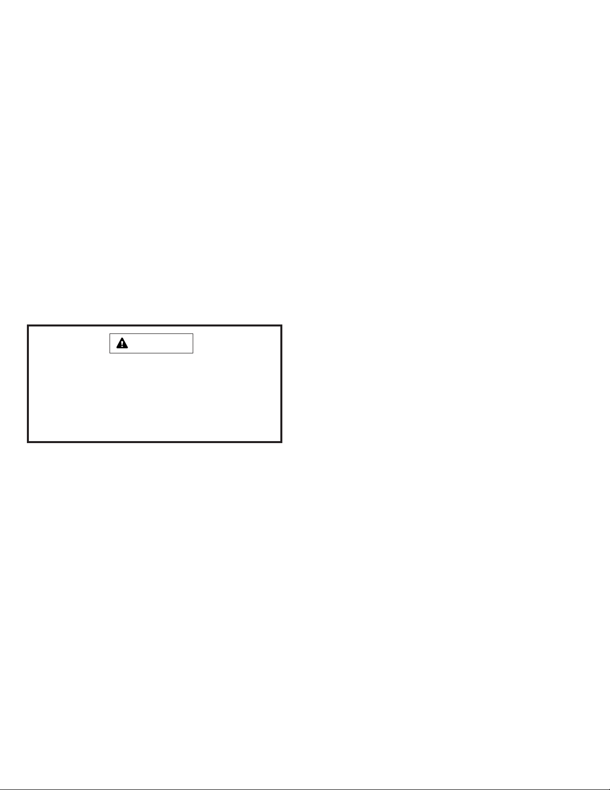
This unit is shipped with four corner brackets in place on the
underside of the unit (see Figure 1). All four brackets must
be removed before unit is installed onto roof curb
assembly.
To avoid interference with roof curb remove the outer most
screw attaching the outdoor coil filler panel to the unit base,
and calk the open hole.
Clearance to combustibles below the unit flue is 10" since
the flue points down.
Do not permit overhanging structures or shrubs to
obstruct condenser air discharge outlet, combustion air
inlet, or vent outlet.
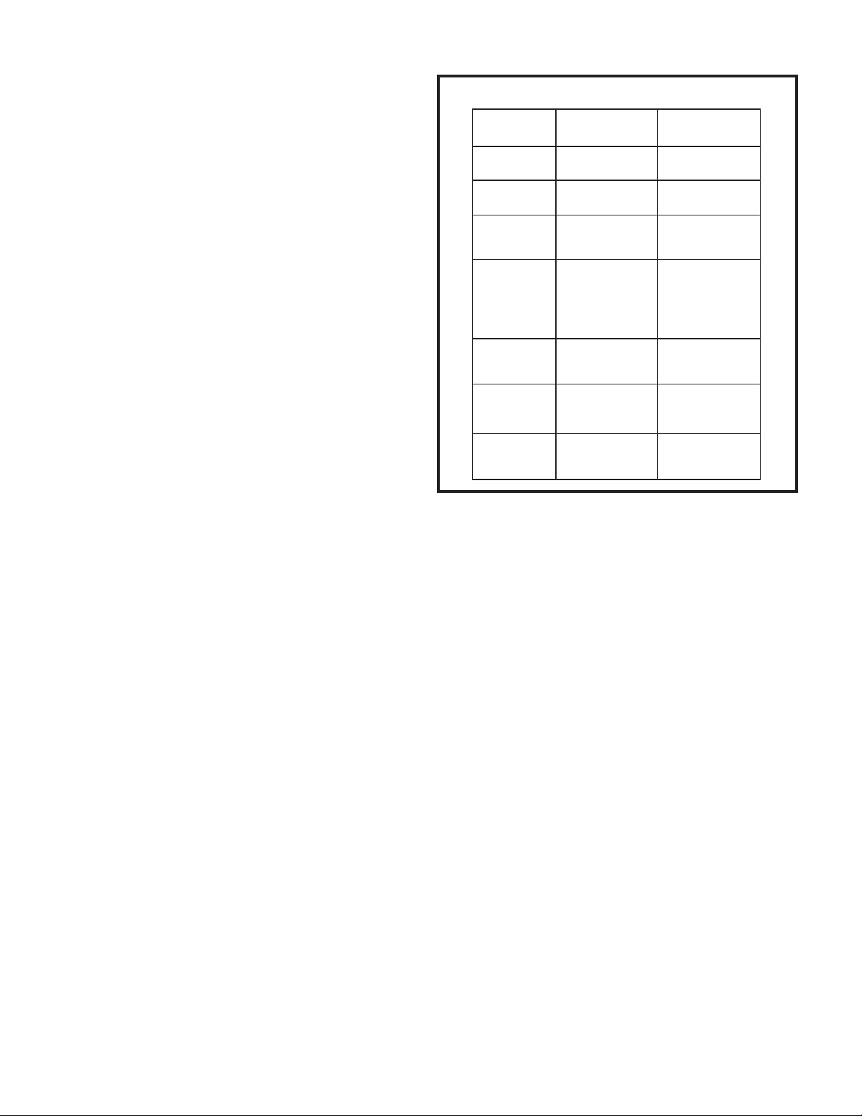
Minimum Clearances to Combustibles
Front of Unit
Back of Unit
Left Side
Right Side
(from Vent Cover)
Below Unit *
* Minimum clearance to combustible material below the flue
is 10" to allow proper dissipation of flue gasses and
temperatures.
24”
2”
12”
15”
0”
T able 1
Corner Brackets
Bracket
Return
Coil Close
Off
Bracket
Remove all four (4) corner brackets before installing on roof curb.
Bracket
Supply
Bracket
Figure 1
In the U.S., units may be installed on combustible floors
made from wood or class A, B, or C roof covering material.
In Canada, units may be installed on combustible floors.
Units must be installed outdoors.
Service Access
Access to all serviceable components is provided by four
removable panels: blower compartment, evoporator coil/filter
compartment, burner compartment, and main control box.
Combustion Discharge
The vent outlet must be installed in a location as to prevent
building degradation and must be consistent with the National
Fuel Gas Code, Z223.1 or CAN/CGA-B149.1 & .2.
The products of combustion are discharged through a
screened opening on the gas heat side panel. The horizontal
vent system shall terminate at least 4' below, 4' horizontally
from, or 1' above any door, window , or gravity air inlet into the
building. The vent system shall terminate at least 3' above
any forced air inlet located within 10'.
The unit shall be installed in a manner such that snow
accumulation will not restrict the flow of flue products.
506271-01 Page 3 of 14Issue 0921
Page 4
Minimum horizontal clearance of 4' from electric meters, gas
meters, regulator, and relief equipment is required.
In addition to the above requirements, consideration must
be given to prevent unwanted ice buildup from the vent
condensate. The vent should not be located on the side of
a building where the prevailing winter winds could trap the
moisture, causing it to freeze on the walls or on overhangs
(under eaves). The vent location should not discharge over
a sidewalk, patio, or other walkway where the condensate
could cause the surface to become slippery .
The products of combustion must not be allowed to
accumulate within a confined space and recirculate.
NOTE:
If a gas furnace that’s connected to a common venting system
is being removed when this package unit is installed, then read
and follow the instructions in the “Removal of Unit from
Common Venting System” section that follows. Otherwise, you
may skip this section.
Removal of Unit from Common Venting System
When an existing furnace is removed from a common venting
system serving other appliances, the venting system is likely
to be too large to properly vent the remaining attached
appliances. The following test should be conducted with each
appliance while the other appliances connected to the common
venting system are not in operation.
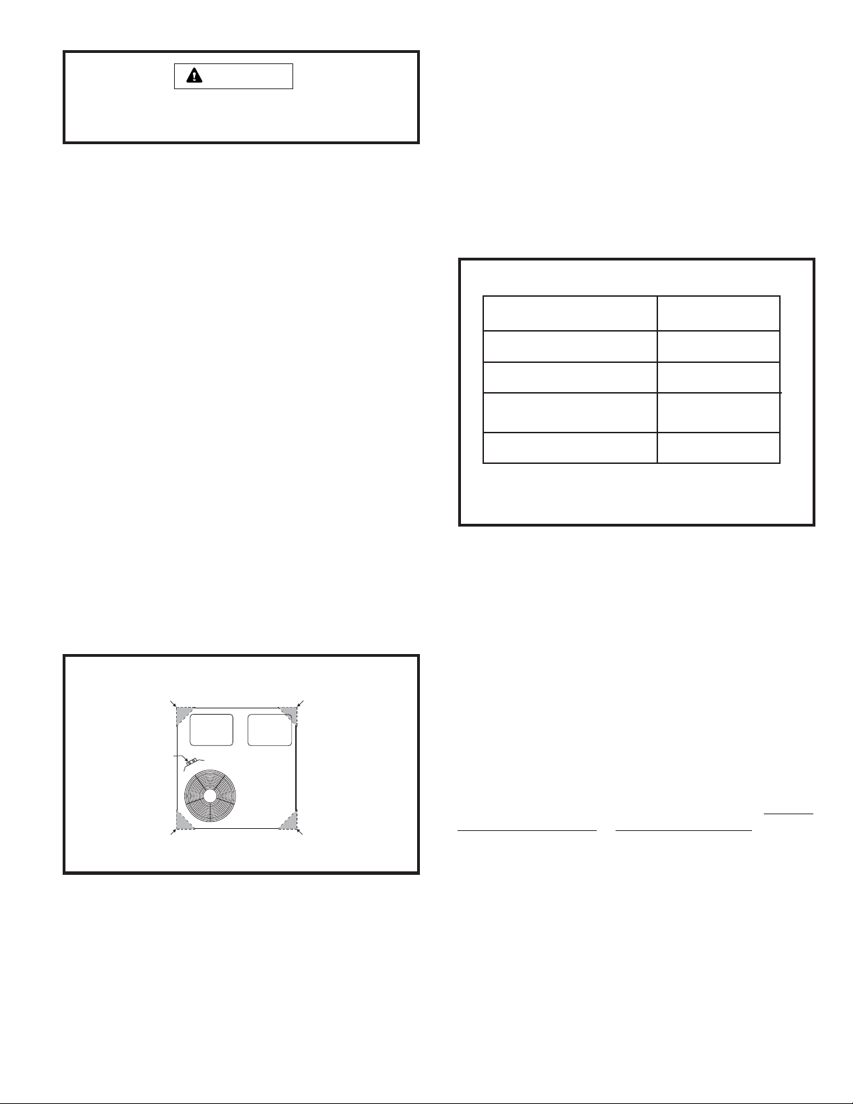
Vent Cover
For shipping purposes, the unit is shipped with the vent cover
packaged in the unit supply air compartment. Retrieve the
vent cover from the supply air compartment.
To attach the vent cover to the unit:
1. Locate the vent screen. It is packed in the plastic bag
that contains these Installation Instructions.
2. Remove the two screws that will be used to attach the
screen to the unit (see Figure 2).
3. Center the screen over the hole and re-insert the screws
removed in Step 2.
4. Remove the 4 screws that will be used to attach the
vent cover (see Fig. 3). Install the vent cover using these
screws. A properly installed vent cover will not extend
above the top of the unit.
Installing the V ent Cover
Screen
1. Seal any unused openings in the common venting
system.
2. Visually inspect the venting system for proper size and
horizontal pitch and determine there is no blockage or
restriction, leakage, corrosion, or other deficiencies
which could cause an unsafe condition.
3. Insofar as is practical, close all building doors and
windows between the space in which the appliances
remaining connected to the common venting system are
located and other spaces in the building. T urn on clothes
dryers and any appliance not connected to the common
venting system. Turn on exhaust fans, such as range
hoods and bathroom exhausts, so they will operate at
maximum speed. Do not operate a summer exhaust
fan. Close fireplace dampers.
4. Following the lighting instructions, place the unit being
inspected in operation. Adjust the thermostat so the
appliance will operate continuously .
5. T est for spillage at the draft control relief opening af ter 5
minutes of main burner operation. Use the flame of a
match or candle.
Screen attachment screws
Vent Cover
Attachment
Screws
(Plus 2 on
other side)
Vent Cover
Figure 2
Page 4 of 14 506271-01Issue 0921
6. Follow the preceding steps for each appliance connected
to the common venting system.
7. After it has been determined that each appliance
remaining connected to the common venting system
properly vents when tested as outlined above, return
doors, windows, exhaust fans, fireplace dampers, and
any other fuel burning appliance to their previous
condition of use.
8. If improper venting is observed during any of the above
tests, the common venting system must be corrected.
See
National Fuel Gas Code, ANSI Z223.1 (latest
edition) or CAN/CGA B149.1 & .2 Canadian
Installation Codes to correct improper operation of
common venting system.
Page 5
Ductwork
Ductwork should be designed and sized according to the
methods in Manual Q of the Air Conditioning Contractors of
America (ACCA).
A closed return duct system shall be used. This shall not
preclude use of economizers or outdoor fresh air intake. It
is recommended that supply and return duct connections at
the unit be made with flexible joints.
The supply and return air duct systems should be designed
for the CFM and static requirements of the job. They should
not be sized by matching the dimensions of the duct
connections on the unit.
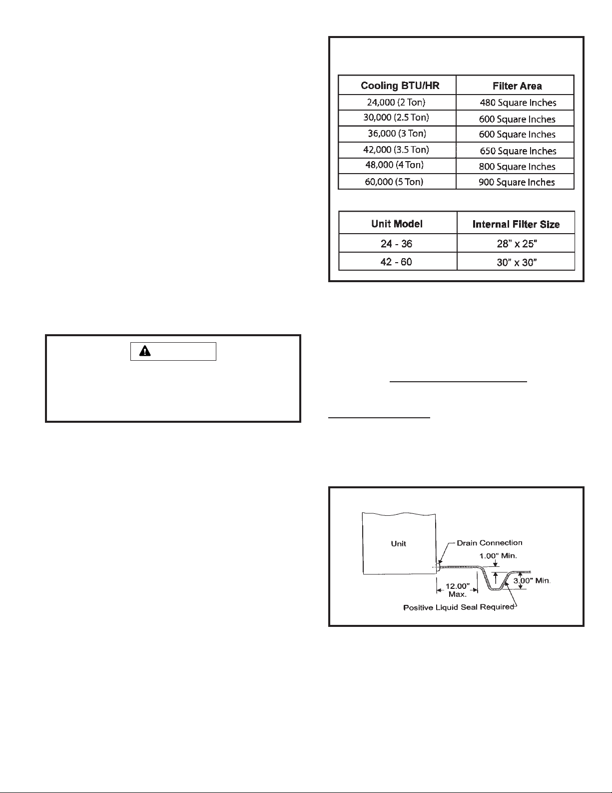
Filters
Filters are not supplied with the unit. Filters must always be
installed ahead of the evaporator coil and must be kept clean
or replaced. Dirty filters will reduce the airflow of the unit.
Filters should be sized in accordance with Table 3.
Minimum Required Surface Area
for Disposable Filters
This unit is equipped with an internal filter clip which is located
in the indoor coil compartment attached to the side of the
unit drain pan.
CAUTION
When fastening ductwork to the side duct flanges on unit,
insert screws through duct flanges only. Do not insert
screws through the casing. Outdoor ductwork must be
insulated and waterproofed.
Condensate Drain
This package unit is equipped with a 3/4" FPT coupling for
condensate line connection. Plumbing must conform to local
codes. Use a sealing compound on male pipe threads.
The condensate drain line must be properly trapped and
routed to a suitable drain. See Figure 3 for proper drain
arrangement. The drain line must pitch to an open drain or
pump to prevent clogging of the line. Seal around the drain
connection with suitable material to prevent air leakage into
the return air system.
T able 2
Gas Piping
Proper sizing of a gas piping depends on the cubic feet per
hour of gas flow required, specific gravity of the gas, and
length of run. National Fuel Gas Code Z223.1 latest edition
should be followed in all cases unless superseded by local
codes or gas company requirements. In Canada, refer to
CAN/CGA B.149.1 & .2 (latest edition).
The heating value of the gas may differ with locality. The
value should be checked with the local gas utility. For
temperature rise of unit, see unit rating plate.
T ypical Condensate Drain Connection
506271-01 Page 5 of 14Issue 0921
Figure 3
Page 6
Gas piping recommendations:
• A drip leg and a ground joint union must be inst alled in
the gas piping. A ground joint union is recommended by
the manifold/valve.
WARNING
Never use a flame to check for gas leaks. Explosion
causing injury or death may occur.
• When required by local codes, a manual shutoff valve
may have to be installed outside of the unit.
• Use pipe thread sealing compound resistant to propane
gas sparingly on male threads.
• The gas supply should be a separate line and installed
in accordance with all safety codes listed on page 1.
After the gas connections have been completed, open
the main shutoff valve admitting normal gas pressure
to the mains. Check all joints for leaks with soapy solution
or other material suitable for the purpose.
• The furnace and its individual manual shutoff valve must
be disconnected from the gas supply piping system
during any pressure testing of that system at test
pressures in excess of 1/2 PSIG (3.48kPa).
• A 1/8" N.P.T . plugged tapping, accessible for test gauge
connections, must be installed immediately upstream
of the gas supply connection to the furnace.
Gas Connection
The gas supply line should be routed through the grommet
on the side of the unit.
WARNING
The furnace must be isolated from the gas supply piping
system by closing the individual manual shutoff valve
during any pressure testing of gas supply piping system
at test pressures equal to or less than 1/2 psig or 14"
w.c. If the piping system is to be tested at pressures in
excess of 1/2 psig, the furnace and its individual shutoff
valve must be disconnected from the gas supply piping
system.
T ypical Field Wiring
48" Over head
24" Clearan ce
From Fron t
Clearance
Gas Entry
Disconn ect Switch
To Unit Power Entry
Vent Cover
15" Clearance
To Vent Cover
Power Entry
Low Voltage Entry
Weathe rproof
12" Clearanc e
(Both Sides)
Thermostat
To
Power
Supply
NEC Class 1 Wiring
NEC Class 2 Wiring
To Low Voltage E ntry
2" C learanc e Rear
NOTE: All outdo or wiring must be weat herproof.
Figure 4
Page 6 of 14 506271-01Issue 0921
Page 7

LPG/Propane Units, Tanks, and Piping
Units are shipped equipped for natural gas, but can be
converted to LPG/propane in the field by an approved
licensed technician. If conversion is required, use the
approved conversion kit.
When converting a low NO
unit (designated by an L in the
x
model number) to propane, the NOx inserts must be
removed. After removing the burners, remove the screw
holding each insert and pull the insert from the combustion
chamber. The screws must be reinst alled in the vest panel
after the inserts are removed.
All LPG/propane gas equipment must conform to the safety
standards of the National Fire Protection Association.
For satisfactory operation, LPG/propane gas pressure must
be a minimum of 1 1" w.c. at the unit under full load.
Complete information regarding tank sizing for vaporization,
recommended regulator settings, and pipe sizing is available
from most regulator manufacturers and LPG/propane gas
suppliers.
Check all connections for leaks when piping is completed,
using a soapy solution. Some soaps used for leak detection
are corrosive to certain metals. Carefully rinse piping
thoroughly after completing leak detection.
Electrical Wiring (See Figures 4 & 5)
comply with all applicable codes. A fused disconnect switch
should be field provided for the unit. The switch must be
separate from all other circuits. If any of the wire supplied
with the unit must be replaced, replacement wire must be of
the type shown on the wiring diagram. Electrical wiring must
be sized to carry minimum circuit ampacity marked on the
unit. Use copper conductors only. Each unit must be
wired with a separate branch circuit and be properly fused.
CAUTION
When connecting electrical power and control wiring to
the unit, waterproof type connectors must be used so that
water or moisture cannot be drawn into the unit during
normal operation.
Thermostat
The room thermostat should be located on an inside wall where
it will not be subject to drafts, sun exposure, or heat from
electrical fixtures or appliances. Follow the manufacturer’s
instructions enclosed with thermostat for general installation
procedure. Color-coded insulated wires (#18 AWG) should
be used to connect the thermostat to the unit.
All wiring should be done in accordance with the
National Electrical Code, ANSI/NFPA No. 70 (latest
edition); Canadian Electrical Code Part 1, CSA C22.1
(latest edition); or local codes where they prevail. Use
wiring with a temperature limitation of 75°C minimum. Run
the 208 or 230 volt, 60 hertz electric power supply through a
fused disconnect switch to the control box of the unit and
connect as shown in the wiring diagram located on the inside
of the control access panel.
Power supply to the unit must be N.E.C. Class 1, and must
Power Wiring
Line Volt age 208/230 Volts
CONTACTOR
GROUND
LUG
If 208 volt is supplied, transformer connections must be made.
FIELD-SUPPLIED
FUSED
DISCONNECT
SINGLE
PHASE
POWER
SUPPLY
Figure 5
Four wires are required for cooling. The heat anticipator
setting is 0.75 amp.
Compressor
Units are shipped with compressor mountings factoryadjusted and ready for operation.
Caution: Do not loosen compressor mounting bolts.
506271-01 Page 7 of 14Issue 0921
Page 8
START-UP
For Your Safety Read Before Lighting
To Light Main Burners:
1. Turn of f electrical power to unit.
2. Turn the thermostat to lowest setting.
CAUTION
Furnace is equipped with a direct ignition control. Do not
attempt to manually light the burners.
Pre-Start Check List
Complete the following checks before starting the unit:
1. Check the type of gas being supplied. Be sure it is the
same as listed on the unit nameplate.
2. Make sure that the vent cover has been properly
installed.
T ypical Wiring Connections
3. Turn the gas valve knob to the “ON” position (see Figure
7).
4. Turn on electrical power to the unit.
5. Set the room thermostat to the desired temperature. (If
the thermostat “set” temperature is above room
temperature after the pre-purge time expires, main
burners will light.)
To Shut Down Main Burners:
1. Turn of f electrical power to unit.
2. Turn the gas valve switch to the “OFF” position (see
Figure 7).
Regulator
Gas Valve
Adjustment
(Under Cap)
Gas Control Switch
Figure 7
Post-Start Check List
After the entire control circuit has been energized and the
heating section is operating, make the following checks:
1. Check for gas leaks, using soapy solution, in the unit
piping as well as the supply piping.
2. Check for correct manifold gas pressures (see Manifold
Gas Pressure Adjustment Regulator sections).
3. Check the supply gas pressure. It must be within the
limits shown on the rating plate. Supply pressure should
be checked with all gas appliances in the building at full
fire. At no time should the standby gas pressure exceed
13" w.c., nor the operation pressure drop below 5" w.c.
for natural gas units or 11" w .c. for propane gas. If gas
pressure is outside these limits, contact the gas supplier
for corrective action.
Figure 7
Page 8 of 14 506271-01Issue 0921
4. Adjust temperature rise to the range specified on the
rating plate.
Page 9

Manifold Gas Pressure Adjustment Regulator – Natural
Gas
For purpose of input adjustment, the minimum
permissible gas supply pressure is 5" w.c. for natural gas.
T o check this pressure:
1. Turn off gas valve.
2. Remove plug on valve marked “OUTLET PRESSURE.”
Gas input must never exceed the input capacity shown on
the rating plate. The furnace is equipped for natural gas
rated inputs with manifold pressure of 3.5" w.c.
The manifold pressure can be measured by shutting off the
gas, removing the pipe plug in the downstream side of the
gas valve, and connecting a water manometer or gauge.
Under no circumstances should the final manifold
pressure vary more than 0.3" w.c. from the above
specified pressures. To adjust the regulator, turn the
adjusting screw on the regulator clockwise to increase
pressure and input or counterclockwise to decrease pressure
and input. See Figure 8 to assist in locating the regulator on
the gas valve.
Check the furnace rate by observing the gas meter, making
sure all other gas appliances are turned off. The test hand on
the meter should be timed for at least one revolution, noting
the number of seconds per revolution. The heating value of
the gas can be obtained from the local utility .
Example: By actual measurement, it takes 38 seconds for
Cubic Feet Per RevolutionBTU/HR
INPUT # Seconds Per Revolution
=
x 3600 x
Heating
Value
the hand on the 1-cubic foot dial to make a revolution with a
100,000 BTU/HR furnace running. The result is 99,750 BTU/
HR, which is close to the 100,000 BTU/HR rating of the
furnace.
3. Install a water manometer .
4. Turn on gas valve and initiate a call for heat. If manifold
pressure must be adjusted, remove cap from pressure
regulator and turn adjustment screw clockwise to
increase pressure or counterclockwise to reduce
pressure.
5. After checking pressure, turn gas off, remove
manometer fitting, and replace pipe plug and regulator
cap.
6. Put furnace in operation and check plug for leaks using
soapy solution.
Burner and Burner Orifice Instructions
To check or change burners or burner orifices:
1. Close the main manual gas shutoff valve and turn
off all power to unit.
2. Remove the burner access panel.
3. Disconnect the union in the gas supply line upstream of
the gas valve and downstream of the manual shutoff
valve.
4. Label wires going to the gas valve, then disconnect the
wires.
5. To change orifice:
Manifold Gas Pressure Adjustment Regulator –
LPG/Propane Gas
LPG/propane units require a regulator, and a regulator on
the LPG/propane tank is also required.
For purpose of input adjustment, the minimum
permissible gas supply pressure (inlet side of gas valve)
is 11" w.c. for LPG/propane.
If at any time ignition is slow and burner does not seem to
6. To remove or service burners:
be operating correctly , check manifold pressure (outlet side
of the gas valve). It should be 10" to 10.5" w.c. pressure
for LPG/propane.
The furnace is designed to obtain rated input at 10" w.c.
manifold pressure for propane.
506271-01 Page 9 of 14Issue 0921
a. Remove 4 screws that fasten the manifold to the
burner box assembly and remove the manifold.
b. Remove the orifices, then install replacement
orifices.
c. To reassemble: Reverse above steps, making sure
orifices are inserted into the orifice holders on the back
end of the burners, and that burners are level and
centered on each burner opening in the vest panel.
a. Label and disconnect the wires to the rollout switch
and disconnect the igniter and flame sensor leads at
the ignition control.
b. Remove the 4 screws that secure the burner box
assembly to the vest panel and remove the assembly
from the unit.
c. Remove the 6 screws that fasten the burner rack
and bottom shield assembly to the burner box. Burners
are now accessible for removal.
d. To Reassemble: Reverse above steps.
Page 10
7. After reassembly of all parts is complete and all wires
are reconnected, open the main manual gas shutoff valve;
check for and correct any gas leaks. Turn electrical power
on, initiate a call for heat, and check for proper burner
operation.
8. Install burner access panel.
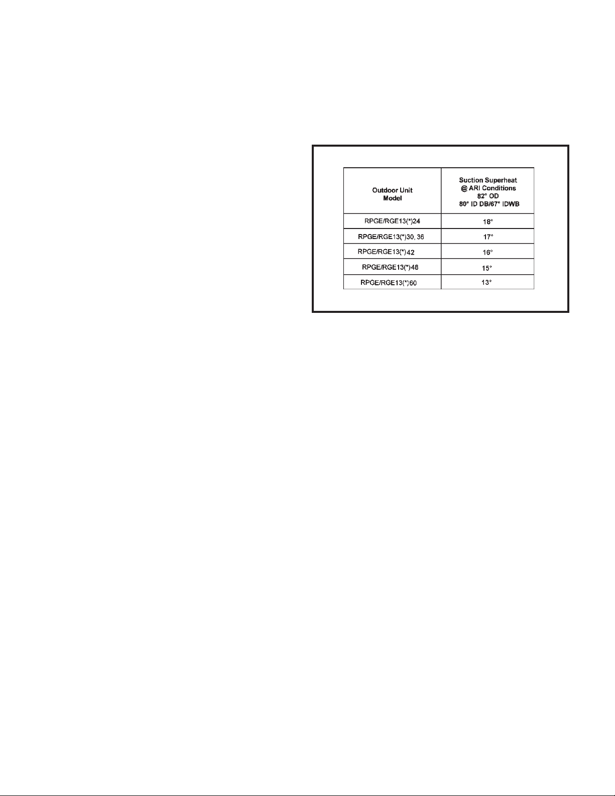
For maximum performance of the cooling system, operating
temperatures and pressure should be checked. Superheat
should be determined at St andard ARI test conditions of 82°F
outdoor and 80°F indoor dry bulb/67°F wet bulb. If superheat
measured deviates from values found in Table 3, refrigerant
charge should be adjusted accordingly for maximum
performance.
does not sense that a flame has been established in the
Heat Anticipator
The heat anticipator setting is 0.75 amp. It is important
that the anticipator setpoint be correct. Too high of a setting
will result in longer heat cycles and a greater temperature
swing in the conditioned space. Reducing the value below
the correct setpoint will give shorter “ON” cycles and may
result in the lowering of the temperature within the
conditioned space.
OPERATION
Cooling System
The cooling system is a complete factory package utilizing an
air-cooled condenser and is factory-charged with HFC-R-410A.
The compressor is hermetically sealed and base mounted
with rubber-insulated hold-down bolts.
Unit compressors have internal protection. In the event there
is an abnormal rise in the temperature of the compressor, the
protector will open and cause the compressor to stop.
Preliminary Operation Cooling
After the initial installation, the compressor should be given
three false starts (energized just long enough to make a few
revolutions), with 5 – 7 minutes between each start, before
being put into full-time service.
Cooling Sequence of Operation
When the thermostat calls for cooling, R is closed to G and
Y (see the wiring diagram found on page 13). This action
completes the low voltage control circuit, energizing the
compressor, condenser fan motor, and blower motor .
Suction Superheat
* This letter will vary according to furnace series.
T able 3
Heating System
With the proper thermostat and sub-base, continuous blower
operation is possible by closing the R to G circuit. Cooling
blower delay is also functional in this mode.
Heating Sequence of Operation
The following sequence describes the operation of the gas
heat section.
1. When the thermostat calls for heat, the draft motor is
energized by the 24-volt relay in the blower ignition control
which closes the 240V contact to the draft motor .
2. When the speed of the draft motor reaches proper RPM,
the pressure switch closes to power the ignition control.
3. When PSW on ignition control is energized, a pre-purge
time is initiated (30 seconds nominal).
Blower Delay – Cooling
The circulating air blower is controlled by a timing circuit in
the integrated blower/ignition control. Timings are not
adjustable. Blower “ON” delay is 5 seconds after the
compressor starts and blower “OFF” timing is 90 seconds
after the cooling system shuts down.
System Performance
Page 10 of 14 506271-01Issue 0921
4. When pre-purge has expired, the gas valve is energized
for direct ignition. The ignition control energizes the main
gas valve and spark electrode for a period of 10 seconds.
5. Thirty seconds nominal after the initial trial for ignition,
the circulation air blower will start. If the flame sensor
Page 11
10-second interval, then the ignition control will deenergize the gas valve.
6. The ignition control is designed to repeat this “trial for
ignition” a total of three times. If, at the end of the third
trial, flame still has not been established, then the ignition
control will try to light again 1 hour later. The 1-hour
retry is indefinite. The ignition control can be reset by
interrupting the unit power or the thermostat circuit.
7. When the thermostat is satisfied, the draft motor and
gas valve are de-energized. The blower motor will
continue to run for a short period after the furnace is
shut down.
Blower Delay – Heating
The on/off delay of the circulating air blower is controlled by
a timing circuit in the integrated ignition control. Timings are
not adjustable. The blower “ON” delay is 30 seconds after
the burners are lit and the blower “OFF” timing is 120
seconds after shutting down the burners.
Safety Controls
The control circuit includes the following safety controls:
High Altitude
The input rate shown on the rating plate is for elevations up
to 2000 feet. For elevations from 2001 to 4500 feet, the
input rate is reduced by 5%. For elevations above 4500 feet,
refer to the National Fuel Gas Code Z223.1 (latest edition)
or the Canadian Installation Codes CAN/CGA-B149.1 &
B149.2 for further details.
Secure Owner’s Approval
When the system is functioning properly, secure the owner’s
approval. Show the owner the location of all disconnect
switches and the thermostat. Instruct the owner on how to
start and stop the unit and how to adjust temperature settings
within the limitations of the system.
MAINTENANCE
Periodic inspection and maintenance normally consists of
changing or cleaning the filters and cleaning the outdoor
coil. On occasion, other components of the furnace may
also require cleaning.
Limit Control This control is located inside the heating
compartment and is designed to open at abnormally high
circulating air temperatures. It resets automatically . The limit
control operates when a high temperature condition, caused
by inadequate airflow, occurs. This closes the main gas valve,
and the circulation air blower continues to operate in this
situation.
Pressure Switch If the draft motor should fail, the pressure
switch prevents the spark electrode and gas valve from being
energized.
Flame Sensor If the ignition control does not receive a
signal from the flame sensor indicating that the burners have
established flame, the main gas valve closes after the 10second trial for ignition period.
Rollout Switch The switch is located on the left side of
burner box. In the event of a sustained main burner rollout,
the rollout switch shuts off the ignition control and closes
the main gas valve. To reset, push the button on top of the
switch.
Auxiliary Limit This control is located in the side of the
circulation air blower housing. The switch opens and shuts
off the blower/ignition control and closes the main gas valve
should the circulation blower fail to operate. This control
resets automatically .
W ARNING
Shut off all electrical power to the unit before conducting
any maintenance procedures. Failure to do so could
cause personal injury .
Filters
Filters are not supplied with the unit. Inspect once a month.
Replace disposable or clean permanent type as necessary.
Do not replace permanent type with disposable.
Motors
Indoor and outdoor fan and vent motors are permanently
lubricated and require no maintenance.
Outdoor Coil
Dirt and debris should not be allowed to accumulate on the
outdoor coil surface or other parts in the air circuit. Cleaning
should be as often as necessary to keep coil clean. Use a
brush, vacuum cleaner attachment, or other suitable means.
If water is used to clean the coil, be sure the power to unit is
shut off prior to cleaning. Care should be used when
cleaning the coil so that the coil fins are not damaged.
Do not permit the hot condenser air discharge to be
obstructed by overhanging structures or shrubs.
506271-01 Page 11 of 14Issue 0921
Page 12
Burners
LED Status
Flashing Rate
Fault
Description
Slow Flash
Fast Flash
2 Flash
3 Flash
4 Flash
5 Flash
Steady
One flash
per second
Normal operaton:
No call for heat
Two flashes
per second
Normal operation:
Call for heat
Two flashes
in second with
1-second pause
Internal failure:
Micro-controller
failure; self-check
Five flashes in
2.5 seconds with
1-second pause
Flame sensed
and gas valve
not energized
Four flashes in
2 seconds with
1-second pause
High limit or
rollout switch
open
Three flashes in
1.5 seconds with
1-second pause
Pressure switch
senses incorrect
pressure or auxiliary
limit is open, or gas
valve coil is open.
System lockout:
Failed to detect
or sustain flame
--
T o clean the burners, first remove them from the furnace as
explained in Burner Instructions on page 9. V acuum and/or
brush as required.
Vent Outlet
Visually inspect vent outlet periodically to make sure that there
is no buildup of soot or dirt. If necessary, clean to maintain
adequate opening to discharge flue products.
Heat Exchanger
With proper combustion adjustment, the heat exchanger of a
gas-fired furnace will seldom need cleaning. Sooting of a gas
appliance is highly irregular and once cleaned, the cause of
the sooting must be determined. If the heat exchanger should
become sooted, it can be cleaned as follows:
1. Remove the burner assembly as outlined in Burner
Instructions on page 9.
2. Remove the combustion blower.
3. At the bottom of the heating section, remove the screws
holding the flue collector box. Carefully remove the flue
collector box without ripping the adjacent insulation.
CONTROL SYSTEM DIAGNOSTICS
Fault Codes
T able 4
4. Using a wire brush on a flexible wand, brush out the
inside of each heat exchanger from the burner inlet and
flue outlet ends.
5. Brush out the inside of the flue collector box.
6. Run the wire brush down the heat exchanger tubes from
the flue collector end.
7. If soot buildup is excessive, remove the vent motor and
clean the wheel and housing. Run the wire brush down
the flue extension at the outlet of the vent housing.
8. After brushing is complete, blow all brushed areas with
9. Replace parts in the reverse order they were removed
10. When replacing the flue collector box, be careful so as
air. Vacuum as needed.
in Steps 1 through 3.
not to tear the adjoining insulation.
1 1. Assure that all joints on the vent side of the combustion
system are air tight. Apply a high temperature (+500°F)
Page 12 of 14 506271-01Issue 0921
sealing compound where needed.
Page 13
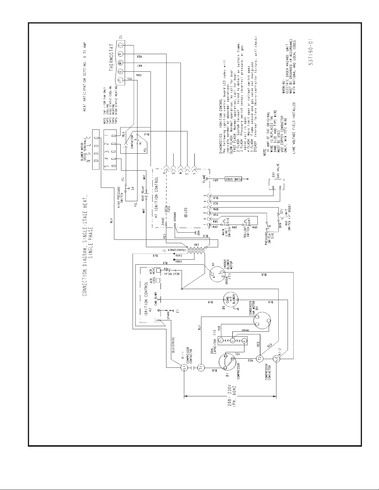
Wiring Diagram – Single Phase
Figure 8
506271-01 Page 13 of 14Issue 0921
Page 14

NOTES
Page 14 of 14 506271-01Issue 0921
 Loading...