

Page 1
INSTALLATION AND MAINTENANCE INSTRUCTIONS
4PGE/SG(13,15) Series
Gas Heating/Electric Cooling Package Unit
Save these instructions for future reference
WARNING
Improper installation, adjustment, alteration, service, or maintenance can cause injury
or property damage. Refer to this manual. For assistance or additional information,
consult a qualified installer, service agency, or the gas supplier.
WARNING
Do not store combustible materials, including gasoline
and other flammable vapors and liquids, near the furnace,
vent pipe, or warm air ducts. Such actions could cause
property damage, personal injury, or death.
WARNING
Never use a flame to check for gas leaks. Explosion
causing injury or death may occur.
WARNING
If this unit is to be installed in a mobile or manufactured
home application, the ductwork must be sized to achieve
static pressures within the manufacturer’s guidelines.
All other installation guidelines must also be followed.
Failure to do so may result in equipment damage,
personal injury, and improper performance of the unit.
TABLE OF CONTENTS
SAFETY ...............................................................2
INSTALLATION ....................................................2
START-UP .......................................................... 10
OPERATION ...................................................... 11
MAINTENANCE ................................................. 13
CONTROL SYSTEM DIAGNOSTICS ................. 14
WIRING DIAGRAMS .......................................... 15
Manufactured By
Allied Air Enterprises Inc.
A Lennox International Inc. Company
215 Metropolitan Drive
West Columbia, SC 29170
*506488-01*
CAUTION
The installation of the furnace, wiring, warm air ducts, venting, etc. must conform to the requirements of the National Fire
Protection Association; the National Fuel Gas Code, ANSI Z223.1 (latest edition) and the National Electrical Code, ANSI/
NFPA No. 70 (latest edition) in the United States; the Canadian Installation Codes CAN/CGA-B149.1 & .2 (latest edition)
and the Canadian Electrical Code Part 1, CSA 22.1 (latest edition) in Canada; and any state or provincial laws, local
ordinances, or local gas utility requirements. Local authorities having jurisdiction should be consulted before installation
is made. Such applicable regulations or requirements take precedence over the general instructions in this manual.
506488-01 Page 1Issue 1008
Page 2
SAFETY
INSTALLATION
The following is a list of safety rules and precautions that
must be followed when installing this furnace.
1. Use only with the type of gas approved for this furnace.
Refer to the furnace rating plate.
2. Install this furnace only in a location and position as
specified in the Location section on page 3 of these
instructions.
3. Adequate clearance must be provided around the vent
hood as specified in the Clearances section on page 4 of
these instructions.
4. Never test for gas leaks with an open flame. Use a
commercially available soap solution made specifically
for the detection of leaks to check all connections, as
specified in Gas Supply and Piping beginning on page
6 of these instructions.
5. Always install furnace to operate within the furnace’s
intended temperature-rise range with a duct system which
has an external static pressure within the allowable range,
as specified in Temperature Rise on page 11 of these
instructions. See furnace rating plate.
These instructions must be hung on or near the furnace
in a conspicuous place.
These units are single package air conditioners with gas heat
designed for outdoor installation on a rooftop or a slab.
The units are completely assembled. All piping, refrigerant
charge, and electrical wiring are factory installed and tested.
The units require only electric power, gas piping, condensate
drain, and duct connections, plus assembly of the heating
vent hood at the point of installation.
If components are to be added to a unit to meet local codes,
they are to be installed at the dealer’s and/or customer’s
expense.
The size of unit for the proposed installation should be based
on heat loss/heat gain calculation made according to the
methods of Air Conditioning Contractors of America (ACCA).
These installation instructions are intended as a general
guide only, for use by an experienced, qualified
contractor.
These units are listed by UL:
6. The furnace is not recommended for use for temporary
heating of buildings or structures under construction unless
certain installation and operating conditions are adhered
to, as specified in the Location section on page 3 of these
instructions.
WARNING
In the State of Massachusetts:
This product must be installed by a licensed Plumber
or Gas Fitter. When flexible connectors are used, the
maximum length shall not exceed 36". When levertype gas shutoffs are used, they shall be T-handle type.
• For use as a forced air furnace with cooling unit.
• For outdoor installation only.
• For installation on combustible material.
• For use with natural gas or propane gas.
(Conversion kit required for propane gas application.)
These units are not suitable for use with conventional
venting systems.
IMPORTANT: The 15 SEER models have been designed
and manufactured to meet ENERGY STAR criteria for energy
efficiency. However, proper refrigerant charge and proper air
flow are critical to achieve rated capacity and efficiency.
Installation of this product should follow the manufacturer’s
refrigerant charging and air flow instructions. Failure to
confirm proper charge and airflow may reduce energy
efficiency and shorten equipment life.
Inspection
As soon as the unit is received, it should be inspected for
possible damage during transit. If damage is evident, the
extent of the damage should be noted on the carrier’s freight
bill. A separate request for inspection by the carrier’s agent
should be made in writing.
Page 2 506488-01Issue 1008
Page 3
Location
Use the following guidelines to select a suitable location for
the unit.
1. Unit is designed for outdoor installation only. Unit must
be installed so all electrical components are protected
from water.
2. Condenser coils must have an unlimited supply of air.
3. For ground level installation, use a level prefabricated
pad or use a level concrete slab. Do not tie the slab to
the building foundation.
4. Maintain level within a tolerance of 1/4" maximum across
the entire length or width of the unit.
5. Do not locate the unit where the combustion air supply
will be exposed to any of the following substances:
• Permanent wave solutions
• Chlorinated waxes and cleaners
• Chlorine-based swimming pool chemicals
• Water softening chemicals
• Deicing salts or chemicals
• Carbon tetrachloride
• Halogen-type refrigerants
• Cleaning solvents (such as perchloroethylene)
• Printing inks, paint removers, varnishes, etc.
• Cements and glues
• Antistatic fabric softeners for clothes dryers
• Masonry acid washing materials
• Chlorinated laundry products
• Hydrochloric acid
Use of unit as a construction heater during any phase of
construction is not recommended. Very low return air
temperatures, harmful vapors, and operation of the unit with
clogged or misplaced filters will damage the unit. However,
if the installation and operating conditions specified below
are followed, use of this unit for heating of buildings or
structures under construction is permissible:
• The vent hood must be installed per these installation
instructions.
• Air filters must be replaced upon construction completion.
• The input rate and temperature rise must be set per the
unit rating plate.
• 100% outdoor air must be provided for combustion air
requirements during construction. Installation of this unit
in its intended outdoor location will accomplish this.
• The heat exchanger, components, duct system, air
filter(s), and evaporator coil must be thoroughly cleaned
following final construction cleanup.
• Following the final cleaning, all furnace operating
conditions (including ignition, input rate, temperature
rise, and venting) must be verified according to these
instructions.
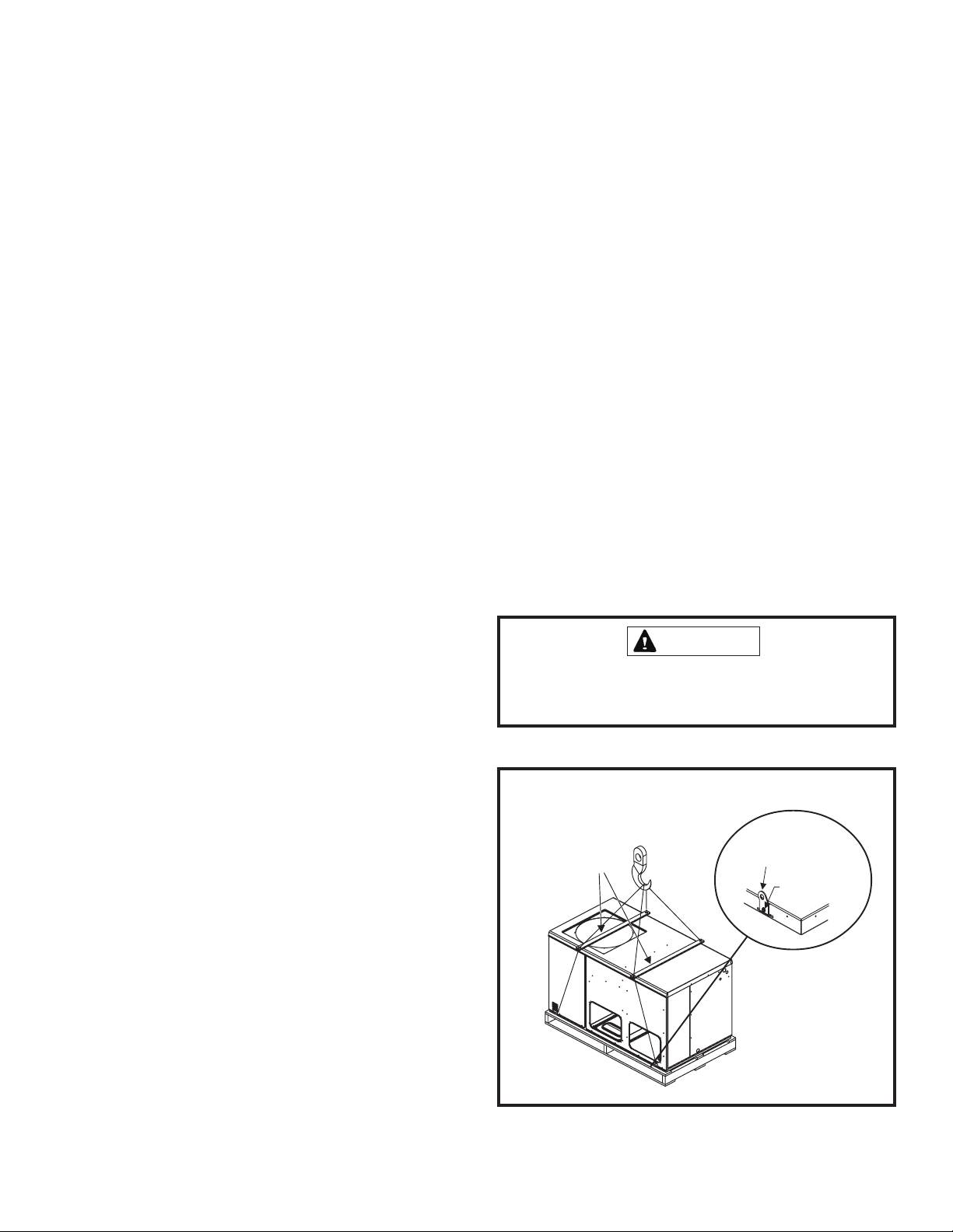
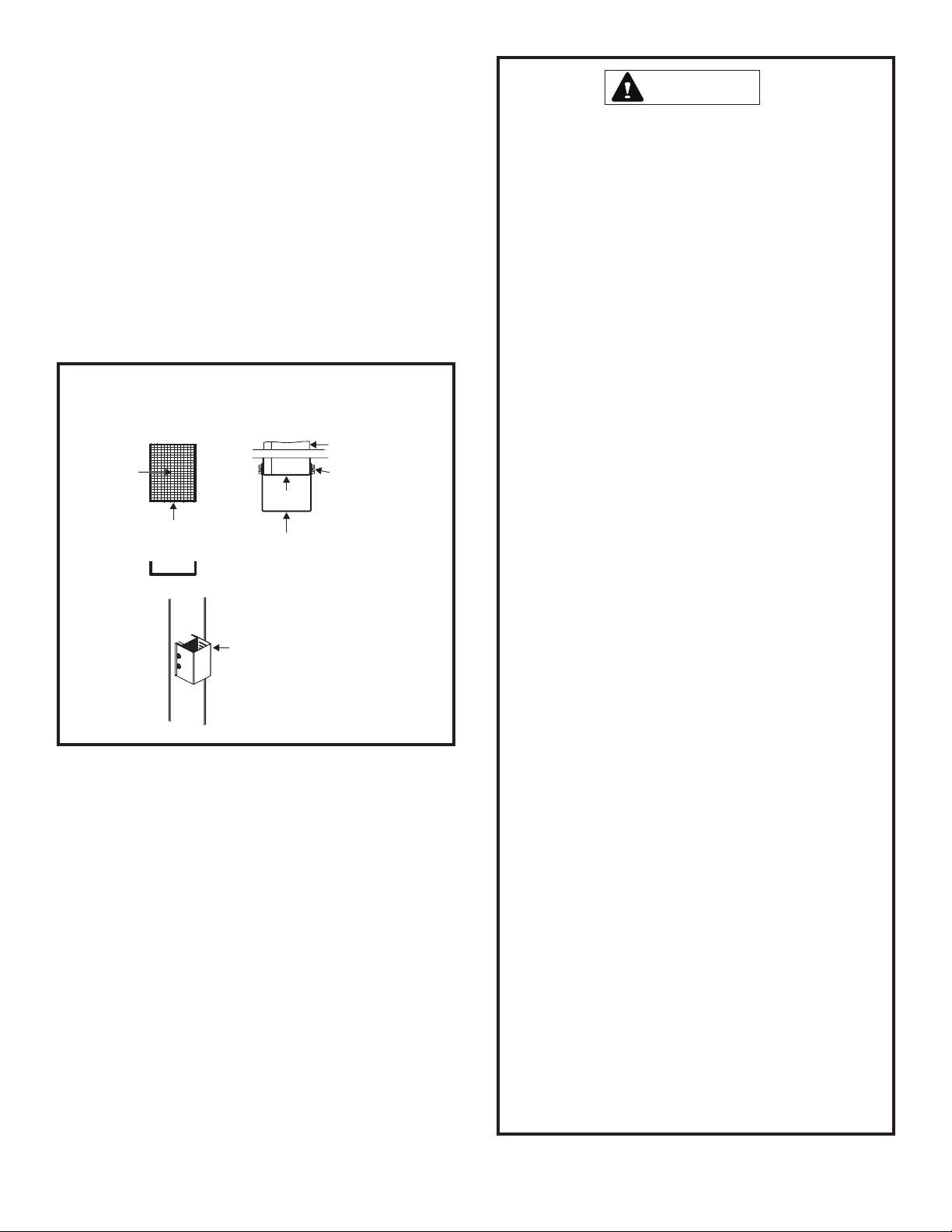
Exercise care when moving the unit. Do not remove any
packaging until the unit is near the place of installation. An
accessory lift kit can be purchased to aid in rigging (see
Figure 1). Spreaders whose length exceed the largest
dimension across the unit must be used across the top of
the unit. Recommended spreader length: 3 ton and smaller
package units – 44", 3.5 ton and larger units – 54".
Units may also be moved or lifted with a forklift while still in
the factory-supplied packaging. The lengths of the forks
of the forklift must be a minimum of 42".
CAUTION
Before lifting a unit, make sure that the weight is
distributed equally on the cables so that it will lift evenly.
Using Accessory Lift Kit
Spreaders
(Field Supplied)
Lifting Bracket
Accessory
Sheet Metal
Screw
• A room thermostat must control the furnace. The use
of fixed jumpers that will provide continuous heating is
not allowed.
• The return air duct must be provided and sealed to the
unit.
• Return air temperature must be maintained between
60°F (16°C) and 80°F (27°C).
• Air filters must be installed in the system and must be
maintained during construction.
506488-01 Page 3Issue 1008
To avoid possible
damage to unit
panels from lifting
clevis, place
packing material
between clevis
and panels before
lifting unit.
Figure 1
Page 4
Roof Curb Installation
If a roof curb is used, follow the manufacturer’s Installation
Instructions and be sure that all required clearances are
observed (see following Clearances section).
Roof Curb Assembly
Figure 2
Clearances
All units require certain clearances for proper operation and
service. Refer to Table 1 for the minimum clearances to
combustibles as well as minimum clearances necessary for
servicing and proper unit operation.
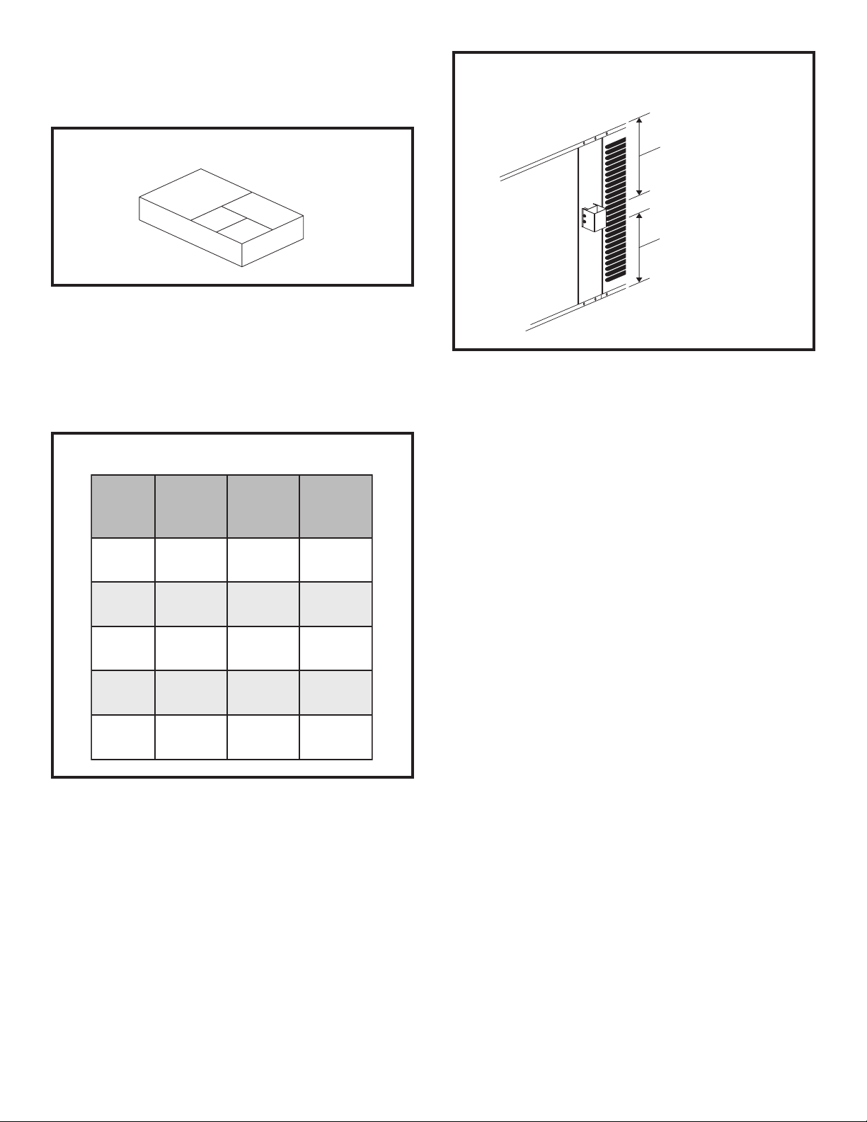
Minimum Clearance Requirements
Minimum Clearance to Combustibles
Above and Below the Vent Hood
Minimum Clearance
Above Vent Hood:
Distance from Top
of Vent Hood to Top
of Unit
Minimum Clearance
Below Vent Hood:
Distance from Bottom
of Vent Hood to Base
of Unit
Figure 3
In the U.S., units may be installed on combustible floors made
from wood or class A, B, or C roof covering material. In Canada,
units may be installed on combustible floors.
oT
elbitsubmoC
lairetaM
tnorF"42"84"3
raeR "0 "42 "3
resnednoC
dnE
rewolB
dnE
poT"0"63"63
"0"42"3
"0 "03 "0
roF
ecivreS
roF
reporP
noitarepO
Table 1
Figure 3 shows the minimum clearances to combustibles
required above and below the vent hood. The minimum
clearance in front of the vent hood is 24".
Do not permit overhanging structures or shrubs to
obstruct condenser air discharge outlet or vent outlet.
Service Access
Access to all serviceable components is provided by four
removable panels: filter compartment, blower compartment,
furnace compartment, and top panel.
Combustion Products Discharge
The unit must be positioned such that combustion products
discharged at the vent outlet will not result in building
degradation and must be consistent with the National Fuel
Gas Code, Z223.1 or CAN/CGA-B149.1 & .2.
The products of combustion are discharged through a
screened opening in the front mullion. The horizontal vent
system shall terminate at least 4' below, 4' horizontally from,
or 1' above any door, window, or gravity air inlet into the
building. The vent system shall terminate at least 3' above
any forced air inlet located within 10'.
The unit shall be installed in a manner such that snow
accumulation will not restrict the flow of flue products.
In addition to the above requirements, consideration must
be given to prevent unwanted ice buildup from the vent
condensate. The vent should not be located on the side of
a building where the prevailing winter winds could trap the
moisture, causing it to freeze on the walls or on overhangs
(under eaves). The vent location should not discharge over
Page 4 506488-01Issue 1008
Page 5
a sidewalk, patio, or other walkway where the condensate
could cause the surface to become slippery.
The products of combustion must not be allowed to
accumulate within a confined space and recirculate.
WARNING
CARBON MONOXIDE POISONING HAZARD
Vent Hood
The unit is shipped with the vent hood, screen, and sheet
metal screws packed in the plastic bag containing the
Installation Instructions.
To attach the vent hood and screen to the unit:
1. Insert the vent screen into the vent tube so that the screen
is flush with the end of the tube, as shown in Figure 4.
Installing Vent Hood
Front View
Screen
Vent Tube
Screen is pre-formed
Top View
Screen
Vent Hood
Slotted side of
vent hood faces
condenser coil.
Vent Tube
NOTE:
Screws should
pass through
sides of screen
to hold screen
in place.
Figure 4
2. Position the vent hood over the vent tube so that the
slotted side of the hood faces the condenser coil. Use
the four sheet metal screws (provided) to secure the
vent hood to the vent tube. The screws should pass
through the sides of the screen in order to hold the
screen in place.
Existing Venting Systems
When an existing furnace is removed or replaced, the original
venting system may no longer be sized to properly vent the
attached appliances. An improperly sized venting system can
result in spillage of flue products into the living space, the
formation of condensate, leakage, etc. See the accompanying
WARNING box for proper test procedure.
Failure to follow the steps outlined below for each
appliance connected to the venting system being
placed into operation could result in carbon monoxide
poisoning or death.
The following steps shall be followed for each appliance
connected to the venting system being placed into
operation, while all other appliances connected to the
common venting system are not in operation:
1. Seal any unused openings in the common venting
system.
2. Visually inspect the venting system for proper size
and horizontal pitch, as required in the National Fuel
Gas Code, ANSI Z223.1/NFPA 54 (latest edition) or
the CSA B149.1, Natural Gas and Propane
Installation Codes and these instructions. Determine
that there is no blockage or restriction, leakage,
corrosion, or other deficiencies which could cause
an unsafe condition.
3. As far as practical, close all building doors and
windows between the space in which the
appliance(s) connected to the venting system are
located and other spaces in the building.
4. Close fireplace dampers.
5. Turn on clothes dryers and any appliance not
connected to the venting system. Turn on any
exhaust fans, such as range hoods and bathroom
exhausts, so they are operating at maximum speed.
Do not operate a summer exhaust fan.
6. Follow the lighting instructions. Place the unit being
inspected in operation. Adjust the thermostat so
appliance is operating continuously.
7. Test for spillage from draft hood equipped appliances
at the draft hood relief opening after 5 minutes of
main burner operation. Use the flame of a match or
candle.
8. If improper venting is observed during any of the
above tests, the venting system must be corrected
in accordance with the National Fuel Gas Code,
ANSI Z223.1/NFPA 54 (latest edition) and/or the
CSA B149.1, Natural Gas and Propane Installation
Codes.
9. After it has been determined that each appliance
remaining connected to the venting system properly
vents when tested as outlined above, return doors,
windows, exhaust fans, fireplace dampers, and any
other gas-fired burning appliance to their previous
conditions of use.
506488-01 Page 5Issue 1008
Page 6

Condensate Drain
The PGE/SG package unit is equipped with a 3/4" FPT
coupling for condensate line connection. Plumbing must
conform to local codes. Use a sealing compound on male
pipe threads.
The condensate drain line must be properly trapped and
routed to a suitable drain. See Figure 5 for proper drain
arrangement. The drain line must pitch to an open drain or
pump to prevent clogging of the line. Seal around the drain
connection with suitable material to prevent air leakage into
the return air system.
Typical Condensate Drain Connection
3. Slide duct cover out the side duct opening.
Filters
Air filters are to be used with this heating/cooling unit. Filters
are not factory supplied in the unit. However, a filter frame
accessory is available from the manufacturer that allows
Removing Bottom Duct Covers
2
1
Unit
Positive Liquid Seal Required
Drain Connection
1.00" Min.
12.00"
Max.
3.00" Min.
Figure 5
Ductwork
Ductwork should be designed and sized according to the
methods in Manual Q of the Air Conditioning Contractors of
America (ACCA).
A closed return duct system shall be used. This shall not
preclude use of economizers or outdoor fresh air intake. It
is recommended that supply and return duct connections at
the unit be made with flexible joints.
1. Remove screw and lift.
2. Slide cover to free back pin.
Base
Figure 6
CAUTION
When fastening ductwork to side duct flanges on unit,
insert screws through duct flanges only; do not insert
screws through casing. If using bottom duct work, do
not use screws to secure ductwork to bottom duct
opening under drain pan side. Using screws to secure
bottom duct may damage drain pan.
filters to be installed within the unit. If the filter frame
accessory is not used, a filter must be installed in the duct
work by the installer. Filters must always be installed ahead
of the evaporator coil and must be kept clean or replaced.
Dirty filters will reduce the airflow of the unit. Filters should
be sized in accordance with Table 2.
The supply and return air duct systems should be designed
for the CFM and static requirements of the job. They should
not be sized by matching the dimensions of the duct
connections on the unit.
Outdoor ductwork must be insulated and waterproofed.
Equipment is shipped for side ductwork connection. The unit
can be converted to bottom ductwork connection by
removing the duct covers located over the bottom duct
openings and placing these covers over the side duct
openings (see Figure 6).
To remove the bottom duct cover over supply opening:
1. Remove screw on cover nearest side opening.
2. Lift end of cover slightly and push to slide back screw/
pin free from duct flange.
Page 6 506488-01Issue 1008
Gas Supply and Piping
Refer to the furnace rating plate to make sure the furnace is
equipped to burn the gas supplied (natural or propane). See
LPG/Propane Units, Tanks, and Piping on page 7 for more
information on converting to propane gas.
Gas supply piping should be installed in accordance with
local codes and the regulations of the utility. In the absence
of local codes, the latest edition of the National Fuel Gas
Code ANSI Z223.1 (in the U.S.), or the Natural Gas and
Propane Installation Codes CAN/CGA B149.1 & B149.2 (in
Canada), should be followed. Piping must be of adequate
size to prevent undue pressure drop. Consult the local utility
or gas supplier for complete details on special requirements
for sizing gas piping.
Page 7

Minimum Required Surface Area
for Disposable Filters
gnilooClanimoN
000,4276.2
000,03 33.3
000,6300.4
000,24 76.4
000,8433.5
000,06 76.6
aerAretliF
).tf.qs(
The furnace must be isolated from the gas supply piping
system by closing the individual manual shutoff valve during
any pressure testing of the gas supply piping system at test
pressure equal to or less than 1/2 psig (3.5 kPa) or 14" W.C.
If the piping system is to be tested at pressures in excess of
1/2 psig (3.5 kPa), the furnace and its appliance main gas
valve must be disconnected from the gas supply piping
system.
After gas piping is complete, carefully check all piping
connections (factory and field) for gas leaks. Use a leak
detecting solution or other preferred means. Some soaps
used for leak detection are corrosive to certain metals.
Carefully rinse piping thoroughly after leak detection has
been completed.
Table 2
The gas supply line should be routed through the grommet
on the side of the unit. Refer to Figure 7 to locate this access
opening.
If local codes allow the use of a flexible gas appliance
connector, always use a new listed connector. Do not use a
connector which has previously serviced another gas
appliance.
Gas and Electrical Access
Gas Line Entry
Thermostat
Entry
Line Voltage
Entry
Figure 7
Pipe connections must be tight, and a non-hardening pipe
compound resistant to liquefied petroleum gases should be
used.
WARNING
The gas valve supplied with this furnace is rated at 1/2
psig maximum. Any higher pressure may rupture the
pressure regulator diaphragm and may cause overfiring
of the burners and improper burner operation. The
overfiring may result in the creation of carbon monoxide
which could cause asphyxiation.
LPG/Propane Units, Tanks, and Piping
Units are shipped equipped for natural gas, but can be
converted to LPG/propane in the field by an approved
licensed technician.
WARNING
FIRE OR EXPLOSION HAZARD
Failure to follow the safety warnings exactly could result
in serious injury, death, or property damage.
Never test for gas leaks with an open flame. Use a
commercially available soap solution made specifically
for the detection of leaks to check all connections. A fire
or explosion may result causing property damage,
personal injury, or loss of life.
Install a manual shutoff valve in the gas connection to the
unit, external to the casing, in accordance with local codes.
An 1/8" NPT plugged tapping, accessible for test gauge
connection, must be installed immediately upstream of the
gas supply connection to the unit. A sediment trap (drip leg)
shall be installed as close as practical to the gas supply inlet
of the unit.
506488-01 Page 7Issue 1008
All LPG/propane gas equipment must conform to the safety
standards of the National Fire Protection Association.
For satisfactory operation, LPG/propane gas pressure must
be a minimum of 11" W.C. at the unit under full load.
Complete information regarding tank sizing for vaporization,
recommended regulator settings, and pipe sizing is available
from most regulator manufacturers and LPG/propane gas
suppliers.
Page 8

WARNING
CAUTION
Any conversion of a natural gas unit to propane gas must
be done by qualified personnel using a conversion kit
available from the manufacturer, following the instructions
in the conversion kit. If done improperly, overfiring of the
burners and improper burner operation can result. This
can create carbon monoxide which could cause
asphyxiation.
Check all connections for leaks when piping is completed,
using a soapy solution. Some soaps used for leak detection
are corrosive to certain metals. Carefully rinse piping
thoroughly after completing leak detection.
Electrical Wiring
All wiring should be done in accordance with the
National Electrical Code, ANSI/NFPA No. 70 (latest
edition); Canadian Electrical Code Part 1, CSA C22.1
(latest edition); or local codes where they prevail. Use
wiring with a temperature limitation of 75°C minimum. Run
the electric power supply through a fused disconnect switch
to the connection box of the unit and connect as shown in
the wiring diagram located on the inside of the control access
panel.
When connecting electrical power and control wiring to
the unit, waterproof type connectors must be used so that
water or moisture cannot be drawn into the unit during
normal operation.
Four wires are required for cooling. The heat anticipator setting
is 0.7 amp.
Compressor
Units are shipped with compressor mountings factoryadjusted and ready for operation. Caution: Do not loosen
compressor mounting bolts.
Power supply to the unit must comply with all applicable codes
and the National Electical Code (NEC) or Canadian Electrical
Code (CEC). A fused disconnect switch should be field
provided for the unit. The switch must be separate from all
other circuits.
If any of the wire supplied with the unit must be replaced,
replacement wire must be of the type shown on the wiring
diagram. Electrical wiring must be sized to carry minimum
circuit ampacity marked on the unit. Use copper conductors
only. Each unit must be wired with a separate branch circuit
and be properly fused.
Thermostat
The room thermostat should be located on an inside wall where
it will not be subject to drafts, sun exposure, or heat from
electrical fixtures or appliances. Follow the manufacturer’s
instructions enclosed with thermostat for general installation
procedure. Color-coded insulated wires (#18 AWG) should
be used to connect thermostat to unit.
Page 8 506488-01Issue 1008
Page 9
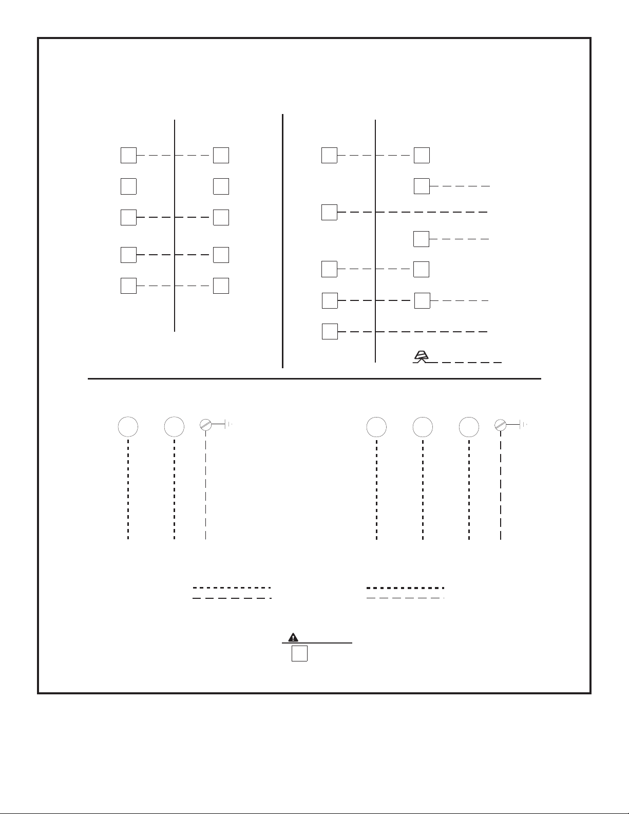
Typical Wiring Connections
C
CAUTION
WITHOUT ECONOMIZER
THERMOSTAT
RR
W
G
OUTDOOR UNIT
CC
YY
W
G
THERMOSTAT
Y1
W
G G
Y2
WITH ECONOMIZER
OUTDOOR UNIT
RR
C
Y
W
ORANGE
ECONOMIZER
BLUE
YELLOW
YELLOW
GREEN
BLACK
(Not Used)
SINGLE PHASE
L2 L1
POWER WIRING
208/230-1-60
(75°C MIN. WIRE)
POWER WIRING
24V CONTROL WIRING
(NEC CLASS 2)
GROUND
SCREW
Do not connect connections except when
required by the indoor thermostat. Refer to the
thermostat installation instructions.
THREE PHASE
L1L2L3
GROUND
SCREW
POWER WIRING
200/230-3-60, 460/575-3-60
(75°C MIN. WIRE)
POWER WIRING
24V CONTROL WIRING
(NEC CLASS 2)
Figure 8
506488-01 Page 9Issue 1008
Page 10

START-UP
For Your Safety Read Before Lighting
CAUTION
Furnace is equipped with a direct ignition control. Do not
attempt to manually light the burners.
Regulator
Adjustment
Cap
Gas Valves
Gas
Control
Knob
Pre-Start Check List
Complete the following checks before starting the unit:
1. Check the type of gas being supplied. Be sure it is the
same as listed on the unit nameplate.
2. Make sure that the vent hood has been properly installed.
To Light Burners:
1. Turn off electrical power to unit.
2. Turn the thermostat to lowest setting.
3. Turn the gas control knob, or slide the gas control switch,
to the “ON” position (see Figure 9).
4. Turn on electrical power to the unit.
5. Set the room thermostat to the desired temperature.
(If the thermostat “set” temperature is above room
temperature, the burners will light after the pre-purge
time expires.)
To Shut Down Burners:
1. Turn off electrical power to unit.
2. Turn the gas control knob, or slide the gas control switch,
to the “OFF” position (see Figure 9).
Inlet Pressure Tap
1/8" NPT
Regulator
Adjustment
Cap
Inlet Pressure Tap
1/8" NPT
Gas Control Switch
Outlet Pressure Tap
(Manifold Pressure)
1/8" NPT
Outlet Pressure Tap
(Manifold Pressure)
1/8" NPT
Figure 9
natural gas or 11" W.C. for propane gas with the burners
in operation. If gas pressure is outside these limits,
contact the gas supplier for corrective action.
4. Adjust temperature rise to be within the range specified
on the rating plate.
Checking and Adjusting Gas Input
For purpose of input adjustment, the minimum
permissible gas supply pressure is 5" w.c. for natural gas
and 11" w.c. for propane.
Post-Start Check List
After the entire control circuit has been energized and the
heating section is operating, make the following checks:
1. Check for gas leaks, using soapy solution, in the unit
piping as well as the supply piping.
2. Check for correct manifold gas pressures (see following
Checking and Adjusting Gas Input section).
3. Check the supply gas pressure. It must be within the
limits shown on the rating plate. Supply pressure should
be checked with all gas appliances in the building at full
fire. At no time should the supply pressure during standby
exceed 13" w.c., nor should it be less than 5" w.c. for
Page 10 506488-01Issue 1008
Gas input must never exceed the input capacity shown on
the rating plate. The furnace is equipped for natural gas
rated inputs with manifold pressure of 3.5" w.c.
The manifold pressure can be measured by shutting off the
gas, removing the pipe plug in the downstream side of the gas
valve, and connecting a water manometer or gauge. To adjust
the regulator, turn the adjusting screw on the regulator
clockwise to increase pressure and input or counterclockwise
to decrease pressure and input. The final manifold pressure
should not vary more than 0.3" w.c. from the above
specified pressure. See Figure 9 to assist in locating the
regulator on the gas valve.
Page 11
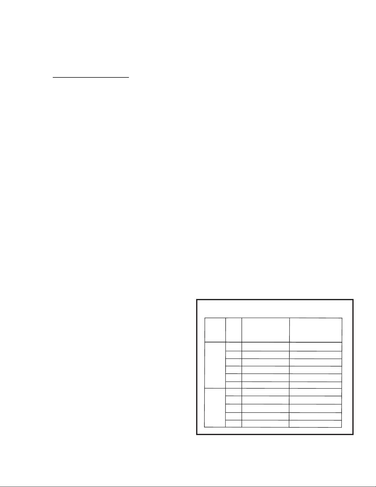
For Natural Gas: Check the gas input rate by observing
Series
Suction Superheat
+/-3 Deg°F @ ARI
Conditions 82° OD,
80° IDDB/67° IDWB
4PGE13
Size
24
17
Liquid Line Subcooling
+/-2 Deg°F @ ARI
Conditions 82° OD,
80° IDDB/67° IDWB
-
30
36
42
48
60
24,30
36
42
48
60
4PGE15
15
19
13
18
15
-
-
-
-
-
12
15
10
7
8
-
-
-
-
-
the gas meter, when available, making sure all other gas
appliances are turned off. The test hand on the meter should
be timed for at least one revolution. Note the number of
seconds for one revolution.
Cubic Feet Per RevolutionBTU/HR
INPUT # Seconds Per Revolution
=
x 3600 x
Heating
Value
The heating value of the gas can be obtained from the local
utility company.
OPERATION
Cooling System
The cooling system is a complete factory package
utilizing an air-cooled condenser. The compressor is
hermetically sealed and base mounted with rubberinsulated hold-down bolts.
Unit compressors have internal protection. In the
event there is an abnormal rise in the temperature of
the compressor, the protector will open and cause the
compressor to stop.
For Propane Gas: The only check for the gas input rate is to
properly adjust the manifold pressure using a manometer.
Typical manifold set point for installations at altitudes from 0 to
4500 feet above sea level is 10.0" W.C.
Temperature Rise
Check the temperature rise and, if necessary, adjust blower
speed to maintain temperature rise within the range shown
on the unit rating plate.
High Altitude
Ratings are shown on the rating plate for elevations up to
4500 feet. For elevations above 4500 feet, ratings should
be reduced at a rate of 4% for each 1000 feet above sea
level. See the National Fuel Gas Code Z223.1 (latest edition)
or the Canadian Installation Codes CAN/CGA-B149.1 &
B149.2 for further details.
Secure Owner’s Approval
When the system is functioning properly, secure the owner’s
approval. Show the owner the location of all disconnect
switches and the thermostat. Instruct the owner on how to
start and stop the unit and how to adjust temperature settings
within the limitations of the system.
Cooling Sequence of Operation
When the thermostat calls for cooling, R is closed to G
and Y (see the wiring diagrams beginning on page 15).
This action completes the low voltage control circuit,
energizing the compressor, condenser fan motor, and
blower motor.
Blower Delay – Cooling
The circulating air blower is controlled by a timing
circuit in the integrated blower/ignition control.
Timings are not adjustable. Blower “on” delay is 5
seconds after the compressor starts and blower “off”
timing is 90 seconds after the cooling system shuts
down.
System Performance
This equipment is a self contained, factory optimized
refrigerant system, and should require no
adjustments when properly installed. If however unit
performance is questioned, perform the following
checks.
Suction Superheat
506488-01 Page 11Issue 1008
Table 3
Page 12

Insure unit is installed per manufacturer’s instructions and
that line voltage and air flows are correct. Refer to Table 3
for proper superheat or subcooling values. Check superheat
settings by measuring pressure at the suction line service
port. For TXV systems, measure pressure at the liquid
service port. Take line temperature within 2 inches of service
port connection to its main tube. If unit superheat/subcooling
varies by more than table allowance, check internal seals,
service panels and duct work for air leaks, as well as
restrictions and blower speed settings. If unit performance
remains questionable, remove charge, evacuate to 500
Microns, and weigh in refrigerant to name plate charge. It is
critical that the exact charge is re-installed. Failure to comply
will compromise system performance. If unit performance
is still questionable, check for refrigerant related problems
such as, blocked coil or circuits, malfunctioning metering
devices or other system components.
in the 10-second interval, then the ignition control will
de-energize the gas valve.
4. The ignition control is designed to repeat this “trial for
ignition” a total of three times. If, at the end of the third
trial, a flame still has not been established, the ignition
control will repeat the trial for ignition sequence 1 hour
later. The 1-hour retry is indefinite. The ignition control
can be reset by interrupting the unit power or the
thermostat circuit.
5. Thirty seconds (nominal) after the initial trial for ignition,
the circulation air blower will start.
6. When the thermostat is satisfied, the combustion blower
and gas valve are de-energized. The circulating air
blower motor will continue to run for a short period after
the thermostat is satisfied.
Heating System
With the proper thermostat and sub-base, continuous blower
operation is possible by closing the R to G circuit. Cooling
blower delay is also functional in this mode.
Heating Sequence of Operation
1. When the thermostat calls for heat, the combustion blower
is energized by the ignition control.
2. When the speed of the combustion blower reaches
proper RPM, the pressure switch closes, initiating the
pre-purge timing (30 seconds nominal).
3. When pre-purge has expired, the ignition control energizes
the gas valve, the spark electrode, and the flame sensor.
The igniter sparks for 10 seconds, and the flame sensor
senses that flame has been established. If the flame
sensor does not sense that flame has been established
Adjusting Airflow (Variable Speed Motor Equipped Units Only)
ledoM
lanimoN
gnilooC
UTBk
gnitaeH
tupnI
UTBk
rotoM
PH
03,42863/1MRONA0001008006009
63 86 2/1 MRON B 0021 0001 008 0011
63092/1MRONA002100010080011
06,84,24 38 4/3 MRON C 0081 0061 0041 0021
06,84,240114/3MRONC0081006100410021
06,84,24 831 4/3 MRON A 0081 0061 0041 0021
TSUJDA
TAEH
gnitteS
Circulating Air Blower
Depending on the package unit model, the blower motor will
be either a multi-tap PSC motor or a variable speed motor.
PSC Motor
The circulating air blower is controlled by a timing circuit in the
integrated blower/ignition control. Timings are not adjustable.
Cooling – Blower “on” delay is 5 seconds after call for
cooling. Blower “off” delay is 90 seconds after the cooling
system shuts down.
Heating – Blower “on” delay is 30 seconds nominal after
burner ignition. Blower "off" delay is approximately 120
seconds after the thermostat is satisfied.
citatS05.@MFCgnilooC
gnitteS
LOOC
gnitteS
A
LOOC
gnitteS
B
LOOC
gnitteS
C
LOOC
gnitteS
D
ADJUST, HEAT,
and COOL Taps
and Dehumidify
Resistor
on Interface
Board
NORM A
A
(+)
B
(–)
C
TEST
D
D1
DEHUMIDIFY
CUT TO ENABLE
COOLHEATADJUST
B
C
D
Table 4
Page 12 506488-01Issue 1008
Page 13
Variable Speed Motor
Units equipped with a variable speed circulation air blower
motor will deliver a constant airflow within a wide range of
external static pressures. Other features of this variable
speed motor include:
Soft Start/Stop – The variable speed motor will slowly ramp
up to normal operating speed. This minimizes noise and
increases comfort by eliminating the initial blasts of air
encountered with standard motors. At the end of a cooling
or heating cycle, the motor will slowly ramp down.
Circulation Airflow Adjustments – The controls include a
variable speed motor interface board. The ADJUST tap can
be used to raise (+) or lower (–) the airflow by 15%.
Heating and Cooling Airflows – The units are factory set
for the correct heating and cooling airflows. However, airflow
changes can be made by moving the position of the HEAT
and COOL taps (see Table 4).
Continuous Blower – The comfort level of the living space
can be enhanced when using this feature by allowing
continuous circulation of air between calls for cooling or
heating. The continuous circulation of air occurs at half the
full cooling airflow rate. To use this feature, place the
thermostat fan switch into the ON position.
Cooling Airflow Ramp Up – At the beginning of a call for
cooling, the blower will run at 80% of full airflow for 7.5
minutes. This improves the system’s moisture removal and
saves blower power during cooling start.
Reduced Airflow Operation (Dehumidification) – For
situations where humidity control is an issue, the variable
speed motor can be connected to operate at a 25% reduction
in the normal airflow rate. The variable speed motor interface
board provides for connection of a humidistat on the HUM
terminal. When a humidistat is connected, the dehumidifier
resistor on the interface must be cut. The humidistat should
be wired to open during high humidity, which will reduce
blower airflow.
Safety Controls
The control circuit includes the following safety controls:
Limit Control
This control is located inside the heating compartment and is
designed to open at abnormally high air temperatures. It resets
automatically. The limit control operates when a high temperature
condition, caused by inadequate airflow, occurs. This causes
the ignition control to close the gas valve. The circulation air
blower continues to operate in this situation.
Pressure Switch
The pressure switch prevents the gas valve and igniter from
being energized if there is insufficient combustion air due to
a failed combustion blower or a blocked vent.
MAINTENANCE
WARNING
ELECTRICAL SHOCK, FIRE,
OR EXPLOSION HAZARD
Failure to follow the safety warnings exactly could result
in dangerous operation, serious injury, death, or property
damage.
Improper servicing could result in dangerous operation,
serious injury, death, or property damage.
• Before servicing, disconnect all electrical power to
furnace.
• When servicing controls, label all wires prior to
disconnecting. Reconnect wires correctly.
• Verify proper operation after servicing.
Flame Sensor
If the ignition control does not receive a signal from the flame
sensor indicating that the burners have established flame, the
gas valve closes after the 10-second trial for ignition period.
Rollout Switch
The switch is located above the main burners. In the event
of a sustained flame rollout, the rollout switch causes the
ignition control to close the gas valve. To reset, push the
button on top of the switch.
Auxiliary Limit (42, 48, and 60 units only)
This control is located in the side of the circulation air blower
housing. The switch causes the ignition control to close the
gas valve should the circulation blower fail to operate. This
control resets automatically.
It is recommended that this furnace be inspected by a
qualified service technician at the beginning of each heating
season.
Filters
Filters should be checked at least every 6 weeks. Disposable
filters should be replaced when dirty, and cleanable filters
should be cleaned regularly. It is important to keep the air filters
clean, as dirty filters can restrict airflow and the blower and
induced draft motors depend upon sufficient air flowing across
and through them to keep from overheating.
Lubrication
The blower motor and induced draft motor are pre-lubricated
by the manufacturer and do not require further lubricating
attention. However, the motors should be cleaned periodically
to prevent the possibility of overheating due to an accumulation
of dust and dirt on the windings or on the motor exterior.
506488-01 Page 13Issue 1008
Page 14

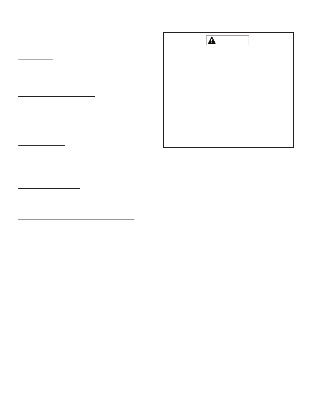
Burners
Light the burners and allow to operate for a few minutes to
establish normal burning conditions. Observe the burner
flames. Compare this observation to Figure 10 on page 14 to
determine if proper flame adjustment is present. Flame should
be predominantly blue in color and strong in appearance.
Check that all burners are lit, and that the flame does not
impinge on the sides of the heat exchanger.
Distorted flame or yellow tipping of the natural gas burner
flame, or long yellow tips on propane, may be caused by lint
accumulation or dirt inside the burner or burner ports, at the
air inlet between the burner and manifold pipe, or
obstructions over the burner orifice.
Use a soft brush or vacuum to clean the affected areas.
Typical Flame Appearance
Heat
Exchanger
Burner
Gas
Manifold
Burner
Flame
(Blue Only)
CONTROL SYSTEM DIAGNOSTICS
Fault Codes
DEL
sutatS
hsalFwolS
hsalFtsaF
hsalF2
hsalF3
hsalF4
hsalF5
ydaetS--
gnihsalF
etaR
hsalfenO
dnocesrep
sehsalfowT
dnocesrep
sehsalfowT
htiwdnocesni
esuapdnoces-1
nisehsalfeerhT
htiwsdnoces5.1
esuapdnoces-1
nisehsalfruoF
htiwsdnoces2
esuapdnoces-1
nisehsalfeviF
htiwsdnoces5.2
esuapdnoces-1
tluaF
niatsusro
nepo
Table 5
noitpircseD
:noitarepolamroN
taehrofllacoN
:noitarepolamroN
taehrofllaC
:tuokcolmetsyS
tcetedotdeliaF
emalf
hctiwserusserP
desolcronepo
rotimilhgiH
hctiwstuollor
desnesemalF
evlavsagdna
dezigreneton
:eruliaflanretnI
rellortnoc-orciM
kcehc-fles;eruliaf
Figure 10
Outdoor Coil
Dirt and debris should not be allowed to accumulate on the
outdoor coil surface or other parts in the air circuit. Cleaning
should be as often as necessary to keep coil clean. Use a
brush, vacuum cleaner attachment, or other suitable means.
If water is used to clean the coil, be sure the power to unit is
shut off prior to cleaning. Care should be used when cleaning
the coil so that the coil fins are not damaged.
Do not permit the hot condenser air discharge to be
obstructed by overhanging structures or shrubs.
Vent Outlet
Visually inspect vent outlet periodically to make sure there is
no buildup of soot and dirt. If necessary, clean to maintain
adequate opening to discharge flue products.
Page 14 506488-01Issue 1008
Page 15

Figure 11
Connection Diagram
Single Phase – PSC Motor
506488-01 Page 15Issue 1008
Page 16

MODULE
DIAGNOSTIC
A132
S1
C
R
W1
G
THERMOSTAT
Y
CONTACTOR
RED
WHT
GRN
YEL
Y
YEL
C
BLU
YEL
R
RED
K1
YEL
A54
HUM
ICM BOARD
R
RED
BLU
SEE
CHART
BLOWER SPEED
C1
EM
W1
A
A
HEAT COOL
ADJUST
NORM
O
B
B
(+)
BLU
BLU
C
C
(-)
Y2
YEL
D
D
(TEST)
GRN
Y1
16
15
14
13
12
11
10
9
8
7
6
5
4
3
2
1
G
GRN
16
15
B3
14
13
12
11
10
9
8
7
6
MOTOR
5
4
3
2
INDOOR BLOWER
1
ADJUST HEAT COOL
Blower Speed Chart
Input
Heating
Unit Factory Shipped Settings
30 68 NORM A A
36 68 NORM B A
36 90 NORM A A
42 83 NORM C C
Input
Cooling
42 110 NORM C C
24 68 NORM A B
48 83 NORM C B
60 83 NORM C A
60 110 NORM C A
48 110 NORM C B
48 138 NORM A B
60 138 NORM A A
ORN
YEL
YEL
S4
SWITCH
(IF USED)
HIGH PRESSURE
IGNITION CONTROL
A3
L1
CMB
A3
IGNITION CONTROL
BLK
BLWR
R
24VAC
RED
RED
BLK
G
FUSE
GROUND
SPARK
L1
E1
W
240V
208V
C
LED
GRN
K1-1
L1
Y
FLAME
3
4
625
1
BLU
24V
T1
B3
543
TRANSFORMER
BLK
BLK
BLK
DUAL
CAPACITOR
COMPRESSOR
CONTACTOR
BLK
T1
GRY
BLU
RED
PUR
PUR
ORN
BRN
MAIN
INDOOR
BRN
F
C12
A132
S10
LIMIT
BLOWER
COMB.
B6
S
C
SWITCH
MOTOR
AIR
BLOWER
PUR
C
R
B1
SENSE
FLAME
S47
WHT
BLU
SWITCH
ROLLOUT
ORN
WHT
B4
H
RED
YEL
RED
T2
A132
COMPRESSOR
GAS
VALV E
GV1
S21
S18
PUR
SWITCH
AUX. LIMIT SWITCH
PRESSURE
WHT
BLK
FAN MOTOR
CONDENSER
BLK
L2
K1-2
CONTACTOR
COMPRESSOR
L2
(IF USED)
DIAGNOSTICS
The following ignition control board LED codes will
indicate normal or abnormal operations:
SLOW FLASH Normal operation, no call for heat.
FAST FLASH Normal operation, call for heat.
2 FLASH System lockout.
3 FLASH Pressure switch senses incorrect pressure.
4 FLASH Main limit open or rollout switch open.
5 FLASH Flame sensed and gas valve not energized.
STEADY Internal failure (micro-controller failure; self check).
NOTE:
IF ANY OF THE ORIGINAL WIRE IS REPLACED, THE
SAME SIZE AND TYPE WIRE MUST BE USED. USE
COPPER CONDUCTOR ONLY, MIN. 75°C WIRE.
WARNING-
ELECTRIC SHOCK HAZARD. UNIT MUST BE GROUNDED
IN ACCORDANCE WITH NATIONAL AND LOCAL CODES.
HEAT ANTICIPATION SETTING: 0.70 AMP
LINE VOLTAGE FIELD INSTALLED
P/N 48107-001
Connection Diagram
Single Phase – Variable Speed Motor
208/230V-1-60
Figure 12
Page 16 506488-01Issue 1008
 Loading...