

Alliance Semiconductor ASM161, ASM162 Service Manual
查询ASM162供应商
October 2003
rev 1.0
General Description
The ASM161 and ASM162 are cost effective, low power
supervisory circuits that monitor power supplies in
microprocessor, microcontroller and digital systems. If the
power supply drops below the reset threshold level, a reset is
asserted and remains asserted for atleast 800ms after V
risen above the reset threshold. An improved manual reset
architecture gives the system designer additional flexibility.
The debounced manual reset input is negative edge triggered.
The reset pulse period generated by a MR
minimum of 800 ms and a maximum of 2 sec duration. In
addition, The MR
minimum after the reset pulse ends. During the MR
period, the microcontroller is guaranteed a time period free of
additional manual reset signals. During this period DRAM
contents can be refreshed or other critical system tasks
undertaken. Low power consumption makes the ASM161/162
ideal for use in portable and battery operated equipments. With
3V supplies power consumption is 8µW typically and 30µW
maximum. The ASM161 has an open-drain, active-LOW
RESET
output and requires an external pull-up resistor. The
ASM162 has an active HIGH RESET output.
input signal is blocked for an additional 49µS
µP Supervisory Circuit
has
CC
transition is a
disable
ASM161 / ASM162
Key Features
• Edge triggered manual reset input
• single pulse output
• 49µS minimum MR
• CMOS/TTL logic or switch interface
• Debounced input
• Low supply current extends battery life
• 6µA / 15µA typ/max at 5.5V
• 4.5µA / 10µA typ/max at 3.6V
• Long reset period
• 0.8 sec minimum, 2 sec maximum
• Two reset polarity options
• ASM161: Active LOW, open-drain
• ASM162: Active HIGH
• Pinout matches the AS811/812
• Small 4-Pin SOT-143 package
• Two temperature ranges: 0
Applications
•PDAs
• Appliances
• Computers and embedded controllers
• Wireless communication systems
• Battery operated and intelligent instruments
• Automotive systems
• Safety systems
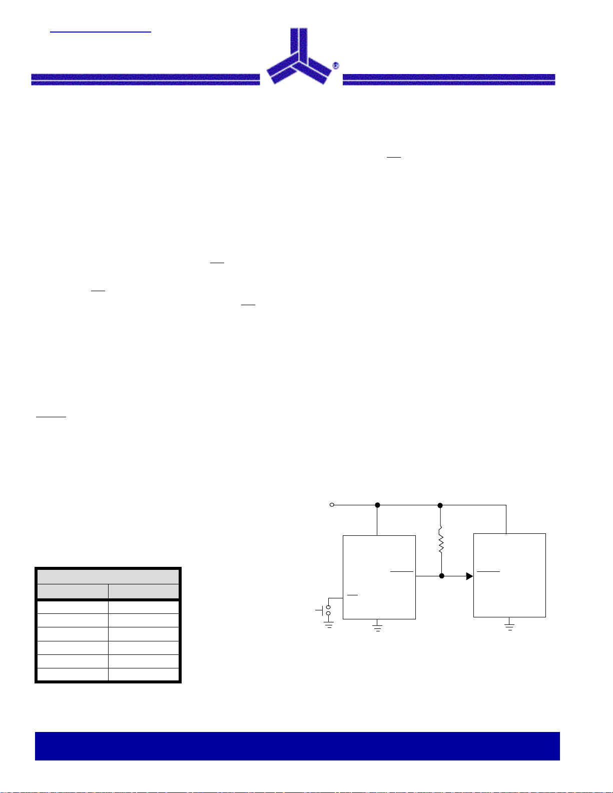
Typical Operating Circuit
disable period after reset
0
0
to 70
c and -400c to +850c
The ASM161/162 are offered in compact 4-pin SOT-143
packages. No external components are required to trim
threshold voltage for monitoring different supply voltages. With
six different factory set, reset, threshold ranges from 2.63V to
4.63V, the ASM161/162 are suitable for monitoring 5V, 3.6V
and 3.0V supplies. The ASM161/162 are available in
temperature ranges 0
Reset Threshold
Part Suffix Voltage (V)
L4.63
M4.38
J4.00
T3.08
S2.93
R2.63
0
to 700c and -400c to +850c.
Alliance Semiconductor
2575 Augustine Drive . Santa Clara, CA 95054 . Tel: 408.855.4900 . Fax: 408.855.4999 . www.alsc.com
Notice: The information in this document is subject to change without notice
V
CC
V
CC
ASM161
(ASM162)
MR
GND
RESET
(RESET)
20k for
ASM161
only
RESET
(RESET)
V
µP
GND
CC
October 2003
rev 1.0
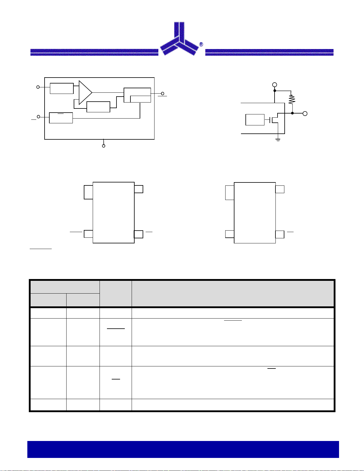
Block Diagram
4
V
CC
MR
Pin Configuration
Voltage
Divider
3
MR
Debounce
* Non-retriggerable, edge
triggered manual reset
ASM161 / ASM162
V
-
+
Bandgap
Reference
1
GND
SOT-143
ASM161/162
Circuit
Reset
* Edge Trigger
2
(ASM161)
RESET
RESET (ASM162)
ASM161
~
~
Reset
Circuit
~
~
SOT-143
CC
4
R
PU
2
GND
1
ASM161
RESET
2
RESET is open drain
Pin Description
Pin #
Pin Name Description
ASM161 ASM162
1 1 GND Ground.
2 - RESET
- 2 RESET
33MR
V
4
CC
GND
1
V
4
CC
ASM162
MR
3
Active-LOW, open-drain reset output. RESET remains LOW while VCC is below the
reset threshold and for 800ms minimum after V
An external pull-up resistor is needed.
Active HIGH reset output. RESET remains HIGH while V
threshold and for 800ms after V
Manual reset input. A negative going edge transition on MR asserts reset. Reset
remains asserted for one reset time-out period (800 ms min). This active-LOW
input has an internal pull-up resistor. It can be driven from a TTL or CMOS logic line
or shorted to ground with a switch. Leave open if unused.
RESET
2
rises above the reset threshold.
CC
CC
rises above the reset threshold.
CC
MR
3
is below the reset
44
V
Notice: The information in this document is subject to change without notice
CC
Power supply input voltage.
2 of 9
µP Supervisory Circuit
October 2003
rev 1.0
ASM161 / ASM162
Detailed Descriptions
The reset function ensures the microprocessor is properly
reset and powers up into a known condition after a power
failure.
Reset Timing
A reset is generated whenever the supply voltage is below
the threshold level (V
800ms after VCC has risen above the reset threshold and is
guaranteed to be no more than 2 seconds. The rest signal
remains active as long as the monitored supply voltage is
below the internal threshold voltage.
The ASM161 has an open-drain, active LOW RESET
(which is guaranteed to be in the correct state for V
to 1.1 V). The ASM161 uses an external pull-up resistor.
Output leakage current is under 1µA. A high resistance value
can be used to minimize current drain.
The ASM162 generates an active-HIGH RESET output.
Part Number Reset Polarity
ASM161 LOW (use external pull-up resistor)
ASM162 HIGH
Manual Reset
The ASM161/162 have a unique manual reset circuit. A
negative going edge transition on MR
manual reset generates a single reset pulse of fixed length.
The output-reset pulse remains asserted for the Reset Active
Time-Out Period t
completed, the MR
but not more than 122µS. This period is specified as t
During the MR
guaranteed a time period free of new manual reset signals.
This period can be used to refresh critical DRAM contents or
other system tasks.
< VTH). The reset duration is at least
CC
output
down
CC
initiates the reset. A
and then clears. Once the reset pulse is
RP
input remains disabled for at least 49µS
disabled period, the microcontroller is
MRD
.
The MR
t
MRD
pulse.
The manual reset input has an internal 20kΩ pull-up resistor.
MR
pin must be taken HIGH and LOW again after the
period has been completed to initiate another reset
can be left open if not used.
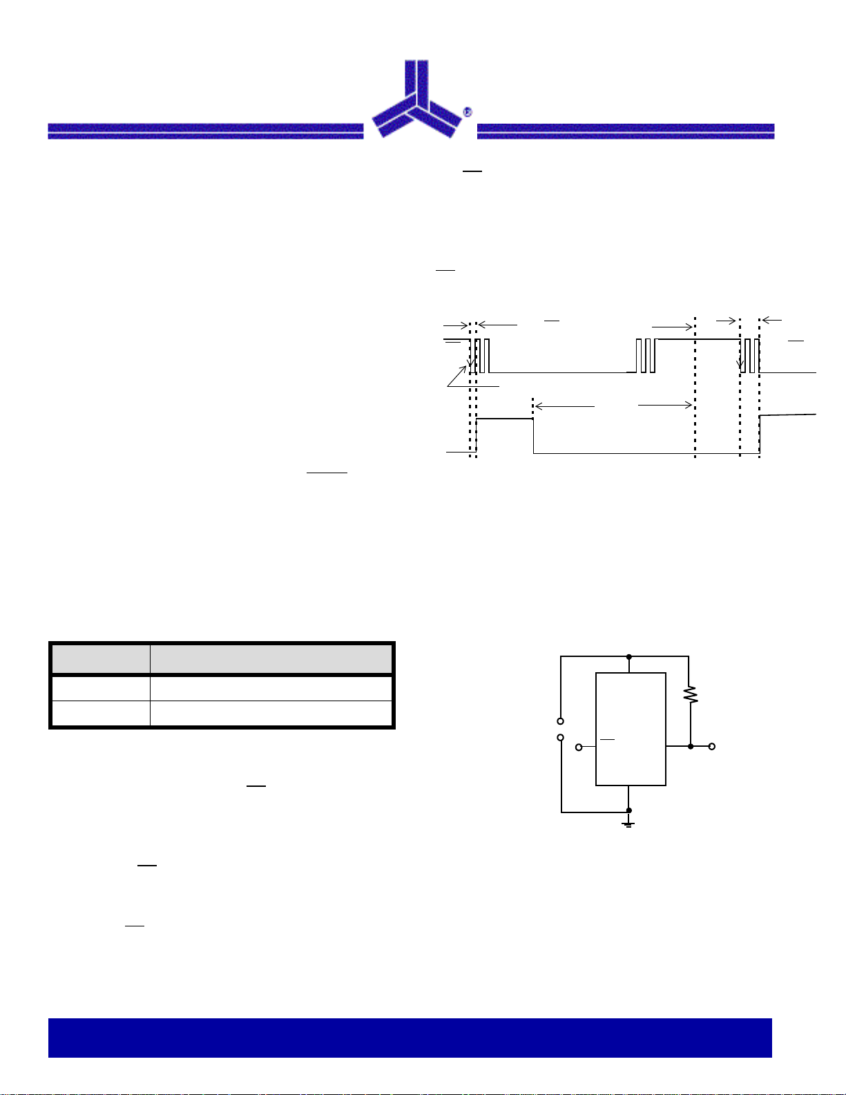
t
MD
MR
RESET
*........
Triggering
Reset
Time-Out
MR input is blocked
Pulse
t
MRD
*Second and following edges ignored
Figure 1: Manual Reset Timing
Application Information
Glitch Resistance
The ASM161/162 are relatively immune to short duration
negative-going V
goes 100mV below the reset threshold and lasts 20s or less
will not typically cause a reset pulse.
Figure 2:
Valid Reset with V
To ensure that logic inputs connected to the ASM162 RESET
pin are in a known state when V
pull-down resistor at RESET is needed. The value is not
critical.
This scheme does not work with the open-drain outputs of
ASM161.
transients/glitches. A VCC transient that
CC
V
Power Supply
ASM162
MR
GND
CC
RESET
100K
Ω
RESET valid with VCC under 1.1V
CC under 1.1V
is under 1.1V, a 100kΩ
CC
Ready
for
next
MR
µP Supervisory Circuit
Notice: The information in this document is subject to change without notice
3 of 9
 Loading...