

Alliance Laundry Systems CA050L, CA050N, CU050N, DR50G2-BA050N, DR50G2-BA050L Installation Manual
...
Tumble Dryers
TMB795C
50 Pound Capacity
75 Pound Capacity
Starting Serial No. 0904004427
Refer to Page 5 for Model Identification
Installation
Keep These Instructions for Future Reference.
(If this machine changes ownership, this manual must accompany machine.)
www.comlaundry.com
TMB795C
Part No. 70420301ENR8
July 2012

Installation must conform with local codes or, in the absence of local codes, with:
• Do not store or use gasoline or other flammable vapors and liquids in the vicinity of this or
any other appliance.
• WHAT TO DO IF YOU SMELL GAS:
– Do not try to light any appliance.
– Do not touch any electrical switch; do not use any phone in your building.
– Clear the room, building or area of all occupants.
– Immediately call your gas supplier from a neighbor’s phone. Follow the gas supplier’s
instructions.
– If you cannot reach your gas supplier, call the fire department.
• Installation and service must be performed by a qualified installer, service agency or the gas
supplier.
W052
FOR YOUR SAFETY, the information in this manual must be followed to minimize the risk
of fire or explosion or to prevent property damage, personal injury or death.
W033
WARNING
In the U.S.A.
NFPA 54 “National Fuel Gas Code” and Standard ANSI/NFPA 70 “National Electric Code.”
In Canada
Installation Code and CSA C22.1, latest edition, Canadian Electric Code, Part I.
In Australia and New Zealand
Part 1: General Installations.
, installation must conform to the latest edition of the American National Standard Z223.1/
, installation must comply with Standards CAN/CSA-B149.1 or Natural Gas and Propane
, installation must comply with the Gas Installations Standard AS/NZS 5601
IMPORTANT: Information must be obtained from a local gas supplier on instructions to be followed if the
user smells gas. These instructions must be posted in a prominent location. Step-by-step instructions of the
above safety information must be posted in a prominent location near the tumble dryer for customer use.
70420301 (EN)
© Copyright, Alliance Laundry Systems LLC – DO NOT COPY or TRANSMIT
1

The following information applies to the state of Massachusetts, USA.
• Installation of unit must be performed by a qualified installer.
• Install tumble dryer according to manufacturer’s instructions and local codes.
• DO NOT install a tumble dryer with flexible plastic venting materials. If flexible metal (foil
type) duct is installed, it must be of a specific type identified by the appliance manufacturer
as suitable for use with tumble dryer. Refer to section on connecting exhaust system.
Flexible venting materials are known to collapse, be easily crushed, and trap lint. These
conditions will obstruct tumble dryer airflow and increase the risk of fire.
W752R1
WARNING
FOR YOUR SAFETY
Do not store or use gasoline or other flammable vapors and liquids in the vicinity of this or
any other appliance.
W053
• This appliance can only be installed by a Massachusetts licensed plumber or gas fitter.
• This appliance must be installed with a 36 inch (91 cm) long flexible gas connector.
• A “T-Handle” type gas shut-off valve must be installed in the gas supply line to this appliance.
• This appliance must not be installed in a bedroom or bathroom.
2
© Copyright, Alliance Laundry Systems LLC – DO NOT COPY or TRANSMIT
70420301 (EN)

Table of
Contents
Introduction......................................................................................... 5
Model Identification ............................................................................. 5
Customer Service.................................................................................. 7
Wiring Diagram .................................................................................... 7
Serial Plate Location............................................................................. 7
Safety Information.............................................................................. 8
Important Safety Instructions ............................................................... 9
Specifications and Dimensions........................................................... 11
Cabinet Dimensions.............................................................................. 12
Exhaust Outlet Locations...................................................................... 13
Gas Connection Locations.................................................................... 14
Electrical Connection Locations........................................................... 15
Steam Connection Locations ................................................................ 16
Installation........................................................................................... 17
Pre-Installation Inspection .................................................................... 17
Location Requirements......................................................................... 18
Position and Level the Tumble Dryer................................................... 19
Bolt-On Angle Option .......................................................................... 19
To Reverse the Loading Door............................................................... 21
Before Placing Tumble Dryer into Service .......................................... 24
Required for CE Models Only.............................................................. 25
Installing CE Gas Drying Tumble Dryers ............................................ 25
General Information......................................................................... 25
Basic Configuration ......................................................................... 27
Specific Conversion Procedures ...................................................... 27
Exhaust Requirements ....................................................................... 30
Layout ................................................................................................... 30
Make-Up Air......................................................................................... 30
Venting ................................................................................................. 30
Individual Venting ........................................................................... 31
Manifold Venting............................................................................. 31
Gas Requirements............................................................................... 35
Gas Supply Pipe Sizing and Looping ................................................... 37
High Altitude Burner Orifice Sizing..................................................... 39
Electrical Requirements..................................................................... 40
Grounding Instructions ......................................................................... 41
For CE Models Only........................................................................ 41
Service/Ground Location ................................................................. 42
To Connect Electrical Service To The Tumble Dryer.......................... 43
Jumper Configuration Instructions ....................................................... 44
Ferrite Ring Installation........................................................................ 44
50 Pound Gas and Steam Models ......................................................... 45
75 Pound Gas and Steam Models ......................................................... 46
50 and 75 Pound Electric Models......................................................... 47
© Copyright 2012, Alliance Laundry Systems LLC
All rights reserved. No part of the contents of this book may be reproduced or transmitted in any form or by any
means without the expressed written consent of the publisher.
70420301 (EN)
© Copyright, Alliance Laundry Systems LLC – DO NOT COPY or TRANSMIT
3

Steam Requirements........................................................................... 48
Piping Recommendations ..................................................................... 49
Installing Steam Trap and Making Condensate
Return Connections ............................................................................ 49
Thermal Oil Prep .................................................................................. 49
Single Drop Timer .............................................................................. 51
Power-Up Mode.................................................................................... 51
Ready Mode.......................................................................................... 51
Start Mode ............................................................................................ 51
Run Mode ............................................................................................. 51
Setting Dry Time Dipswitches.............................................................. 51
Resetting Cycle Time to Zero............................................................... 51
Dipswitch Settings................................................................................ 52
Adjustments......................................................................................... 54
Gas Burner Air Shutter ......................................................................... 54
Airflow Switch...................................................................................... 55
Loading Door Switch............................................................................ 55
Loading Door Catch ............................................................................. 55
Drive Belt.............................................................................................. 56
Nonreversing Models....................................................................... 56
Reversing Models ............................................................................ 56
Removing Tumble Dryer from Service............................................. 59
4
© Copyright, Alliance Laundry Systems LLC – DO NOT COPY or TRANSMIT
70420301 (EN)

Introduction
Model Identification
Information in this manual is applicable to these models:
Gas Steam/Thermal Oil Electric
CA050L
CA050N
CT050L
CT050N
CU050L
CU050N
DR50G2-BA050L
DR50G2-BA050N
DR50G2-BT050D
DR50G2-BT050L
50 Pound
DR50G2-BT050N
DR50G2-BU050L
DR50G2-BU050N
DR55G2-BA050L
DR55G2-BA050N
DR55G2-BT050D
CA075L
CA075N
CT075L
CT075N
CU075L
CU075N
DR75G2-BA075L
DR75G2-BA075N
DR75G2-BT075D
DR75G2-BT075L
75 Pound
DR75G2-BT075N
DR75G2-BU075L
DR75G2-BU075N
DR80G2-BA075L
DR80G2-BA075N
DR80G2-BT075D
DR80G2-BT075L
DR55G2-BT050L
DR55G2-BT050N
DR55G2-BU050L
DR55G2-BU050N
HA050L
HA050N
HT050D
HT050L
HT050N
HU050L
HU050N
IPD50G2-IT050L
IPD50G2-IT050N
SA050L
SA050N
ST050D
DR80G2-BT075N
DR80G2-BU075L
DR80G2-BU075N
HA075L
HA075N
HT075D
HT075L
HT075N
HU075L
HU075N
IPD75G2-IT075L
IPD75G2-IT075N
SA075L
SA075N
ST075D
ST075L
ST075N
ST050L
ST050N
SU050L
SU050N
UA050L
UA050N
UT050L
UT050N
UU050L
UU050N
YT050L
YT050N
YU050L
YU050N
STF75L
STF75N
SU075L
SU075N
UA075L
UA075N
UT075L
UT075N
UTF75L
UTF75N
UU075L
UU075N
YT075L
YT075N
YU075L
YU075N
(see next page for control suffixes)
CT050S
CT050T
CU050S
CU050T
DR50S2-BT050S
DR50S2-BT050T
DR50S2-BU050S
DR50S2-BU050T
DR55S2-BT050S
DR55S2-BT050T
DR55S2-BU050S
DR55S2-BU050T
HT050S
HT050T
HU050S
HU050T
CT075S
CT075T
CU075S
CU075T
DR75S2-BT075S
DR75S2-BT075T
DR75S2-BU075S
DR75S2-BU075T
DR80S2-BT075S
DR80S2-BT075T
DR80S2-BU075S
DR80S2-BU075T
HT075S
HT075T
HU075S
HU075T
IPD50S2-IT050S
IPD50S2-IT050T
ST050S
ST050T
SU050S
SU050T
UT050S
UT050T
UU050S
UU050T
YT050S
YT050T
YU050S
YU050T
IPD75S2-IT075S
IPD75S2-IT075T
ST075S
ST075T
SU075S
SU075T
UT075S
UT075T
UU075S
UU075T
YT075S
YT075T
YU075S
YU075T
CT050E
CU050E
DR50E2-BT050E
DR50E2-BU050E
DR55E2-BT050E
DR55E2-BU050E
HT050E
HU050E
IPD50E2-IT050E
ST050E
SU050E
UT050E
UU050E
YT050E
YU050E
CT075E
CU075E
DR75E2-BT075E
DR75E2-BU075E
DR80E2-BT075E
DR80E2-BU075E
HT075E
HU075E
IPD75E2-IT075E
ST075E
SU075E
UB075E
UT075E
UU075E
YT075E
YU075E
70420301 (EN)
© Copyright, Alliance Laundry Systems LLC – DO NOT COPY or TRANSMIT
5

Introduction
Includes models with the following control suffixes:
3B – reversing DX4 vended
3O – DX4 OPL
3V – DX4 vended
3W – reversing DX4 prep for coin
3X – DX4 prep for coin
BB– reversing basic electronic, coin
BC – basic electronic, coin
BL – basic electronic, central pay
BW – reversing basic electronic, prep
for coin
BX – basic electronic, prep for coin
BY – basic electronic, prep for card
BZ – reversing basic electronic, prep
for card
DO – DMP OPL
DV – DMP vended
DX – DMP prep for coin
EO – OPL electronic
KB – reversing single coin
KC – single coin
KW – reversing prep for coin
KX – prep for coin
KY – prep for card
KZ – reversing prep for card
LB – reversing network adaptable coin
LC – network adaptable coin
LW – reversing network adaptable,
prep for coin
LX – network adaptable, prep for coin
LY – network adaptable, prep for card
LZ – reversing network adaptable,
prep for card
OM – OPL micro
QT – dual digital timer
R3 – reversing DX4 OPL
RD – reversing DMP OPL
RE – reversing OPL electronic
RM – reversing OPL micro
RQ – reversing dual digital timer
RU – reversing UniLinc OPL
SD – single drop
SX – single drop, prep for coin
UO – UniLinc OPL
WB – reversing network ready coin
WC – network ready coin
WW – reversing network ready, prep
for coin
WX – network ready, prep for coin
WY – network ready, prep for card
WZ – reversing network ready, prep
for card
6
© Copyright, Alliance Laundry Systems LLC – DO NOT COPY or TRANSMIT
70420301 (EN)
Introduction
1
0
2
0
4
0
3
0
5
0
6
0
0
1
0
5
PUSH
TO
START
HEAT
COOL
DOWN
HIGH
TEMP
ERATUR
E
LOW
1
5
0
1
1
Customer Service
If literature or replacement parts are required, contact
the source from which the machine was purchased or
contact Alliance Laundry Systems at (920) 748-3950
for the name and address of the nearest authorized
parts distributor.
For technical assistance, call (920) 748-3121.
Wiring Diagram
The wiring diagram is located in the junction or
contactor box.
The wiring diagram part number is in the lower
portion of the electrical data on the serial plate.
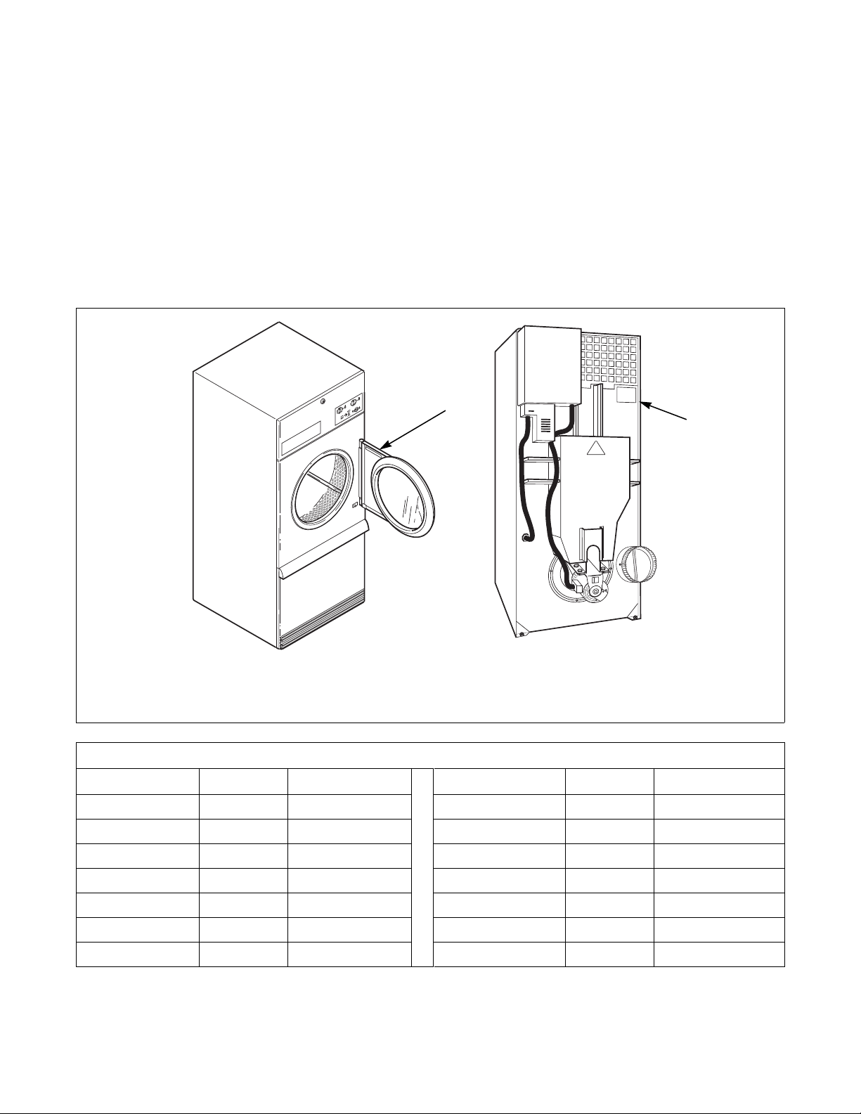
Serial Plate Location
When calling or writing for information about your
product, be sure to mention model and serial numbers.
Model and serial numbers are found on serial plate on
the rear of machine and inside door.
1 Serial Plate
Conversion Table
Multiply By To Obtain Multiply By To Obtain
Btu 0.252 kCal Pounds/sq. inch 0.06895 Bars
Btu 1055 Joules Pounds/sq. inch 0.070 kg/sq. cm
Inch 25.4 Millimeters Pounds (lbs.) 0.454 Kilograms
Inches W.C. 0.036 Pounds/sq. inch Boiler Horsepower 33,479 Btu/hr.
Inches W.C. 0.249 kPa Boiler Horsepower 34.5 lbs. steam/hr.
lb./inch
ft
70420301 (EN)
2
(psi) 6.895 kPa CFM 0.471 liters/second
3
28.32 Liters kW 3414 Btu/hr.
© Copyright, Alliance Laundry Systems LLC – DO NOT COPY or TRANSMIT
TMB2235N
7
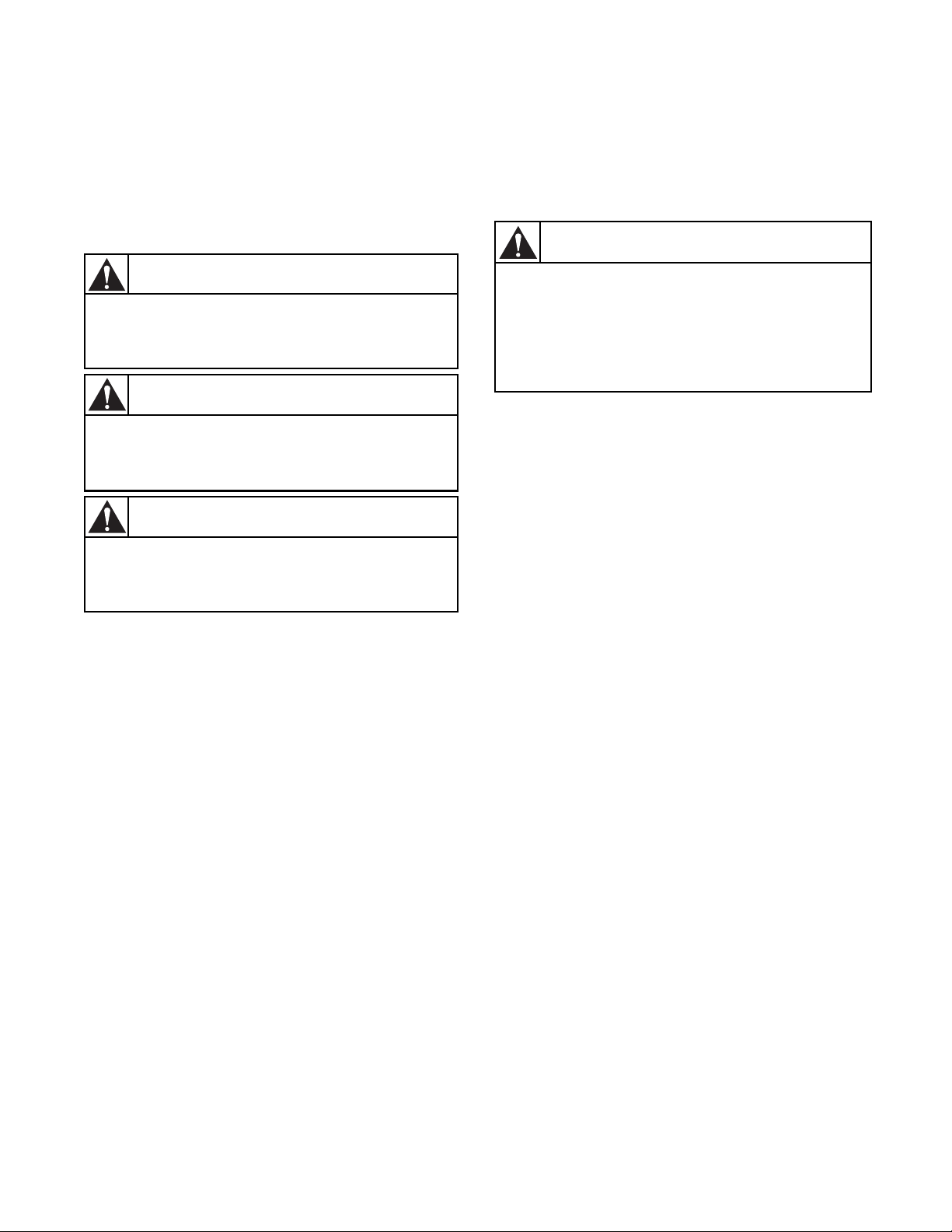
Safety Information
Indicates an imminently hazardous
situation that, if not avoided, will cause
severe personal injury or death.
DANGER
Indicates a hazardous situation that, if not
avoided, could cause severe personal
injury or death.
WARNING
Indicates a hazardous situation that, if not
avoided, may cause minor or moderate
personal injury or property damage.
CAUTION
Failure to install, maintain, and/or operate
this machine according to manufacturer’s
instructions may result in conditions which
can produce serious injury, death and/or
property damage.
W051R1
WARNING
Precautionary statements (“DANGER,” “WARNING,”
and “CAUTION”), followed by specific instructions,
are found in this manual and on machine decals. These
precautions are intended for the personal safety of the
operator, user, servicer, and those maintaining the
machine.
NOTE: The word “NOTE” is used to communicate
installation, operation, maintenance or servicing
information that is important but not hazard
related.
NOTE: The WARNING and IMPORTANT
instructions appearing in this manual are not
meant to cover all possible conditions and
situations that may occur. It must be understood
that common sense, caution and carefulness are
factors which CANNOT be built into this tumble
dryer. These factors MUST BE supplied by the
person(s) installing, maintaining or operating the
tumble dryer.
Additional precautionary statements (“IMPORTANT”
and “NOTE”) are followed by specific instructions.
IMPORTANT: The word “IMPORTANT” is used
to inform the reader of specific procedures where
minor machine damage will occur if the procedure
is not followed.
Always contact your dealer, distributor, service agent
or the manufacturer on any problems or conditions you
do not understand.
8
© Copyright, Alliance Laundry Systems LLC – DO NOT COPY or TRANSMIT
70420301 (EN)

Save These Instructions
Hazardous Voltage. Can cause shock, burn
or cause death. Allow machine power to
remain off for two minutes prior to working
in and around AC inverter drive.
W359
WARNING
Safety Information
Important Safety Instructions
1. Read all instructions before using the tumble
dryer.
2. Refer to the GROUNDING INSTRUCTIONS
for the proper grounding of the tumble dryer.
3. Do not dry articles that have been previously
cleaned in, washed in, soaked in, or spotted with
gasoline, dry cleaning solvents, other flammable
or explosive substances as they give off vapors
that could ignite or explode.
4. Do not allow children on or in the tumble dryer.
This appliance is not intended for use by young
children or infirm persons without supervision.
Young children should be supervised to ensure
that they do not play with the appliance.
5. Before the tumble dryer is removed from service
or discarded, remove the door to the drying
compartment and the door to the lint
compartment.
6. Do not reach into the tumble dryer if the cylinder
is revolving.
7. Do not install or store the tumble dryer where it
will be exposed to water and/or weather.
8. Do not tamper with the controls.
9. Do not repair or replace any part of the tumble
dryer, or attempt any servicing unless specifically
recommended in the user-maintenance
instructions or in published user-repair
instructions that you understand and have the
skills to carry out.
13. Keep area around the exhaust opening and
adjacent surrounding area free from the
accumulation of lint, dust and dirt.
14. The interior of the tumble dryer and the exhaust
duct should be cleaned periodically by qualified
service personnel.
15. If not installed, operated and maintained in
accordance with the manufacturer’s instructions
or if there is damage to or mishandling of this
product’s components, use of this product could
expose you to substances in the fuel or from fuel
combustion which can cause death or serious
illness and which are known to the State of
California to cause cancer, birth defects or other
reproductive harm.
16. Tumble dryer will not operate with the loading
door open. DO NOT bypass the door safety
switch to permit the tumble dryer to operate with
the door open. The tumble dryer will stop
tumbling when the door is opened. Do not use the
tumble dryer if it does not stop tumbling when
the door is opened or starts tumbling without
pressing or turning the START mechanism.
Remove the tumble dryer from use and call for
service.
17. Tumble dryer will not operate with lint panel
open. DO NOT bypass lint panel safety switch to
permit the tumble dryer to operate with the lint
panel open.
18. Do not put articles soiled with vegetable or cooking
oil in the tumble dryer, as these oils may not be
removed during washing. Due to the remaining
oil, the fabric may catch on fire by itself.
19. To reduce the risk of fire, DO NOT put clothes
which have traces of any flammable substances
such as machine oil, flammable chemicals,
thinner, etc. or anything containing wax or
chemicals such as in mops and cleaning cloths, or
anything dry-cleaned at home with dry-cleaning
solvent in the tumble dryer.
10. Do not use fabric softeners or products to
eliminate static unless recommended by the
manufacturer of the fabric softener or product.
11. To reduce the risk of fire, DO NOT DRY plastics
or articles containing foam rubber or similarly
textured rubberlike materials.
12. Always clean the lint filter daily.
70420301 (EN)
© Copyright, Alliance Laundry Systems LLC – DO NOT COPY or TRANSMIT
20. Use the tumble dryer only for its intended
purpose, drying fabrics.
21. ALWAYS disconnect and lockout the electrical
power to the tumble dryer before servicing.
Disconnect power by shutting off appropriate
breaker or fuse.
9

Safety Information
WARNING
To reduce the risk of serious injury, install
lockable door(s) to prevent public access
to rear of tumble dryers.
W055R1
22. Install this tumble dryer according to the
INSTALLATION INSTRUCTIONS. All
connections for electrical power, grounding, and
gas supply must comply with local codes and be
made by licensed personnel when required.
23. Remove laundry immediately after tumble dryer
stops.
24. Always read and follow manufacturer’s
instructions on packages of laundry and cleaning
aids. Heed all warnings or precautions. To reduce
the risk of poisoning or chemical burns, keep
them out of reach of children at all times
(preferably in a locked cabinet).
25. Do not tumble fiberglass curtains and draperies
unless the label says it can be done. If they are
dried, wipe out the cylinder with a damp cloth to
remove particles of fiberglass.
26. Always follow the fabric care instructions
supplied by the garment manufacturer.
27. Never operate the tumble dryer with any guards
and/or panels removed.
28. DO NOT operate the tumble dryer if it is
smoking, grinding, has missing or broken parts.
29. DO NOT bypass any safety devices.
30. Solvent vapors from dry-cleaning machines
create acids when drawn through the heater of the
drying unit. These acids are corrosive to the
tumble dryer as well as to the laundry load being
dried. Be sure make-up air is free of solvent
vapors.
31. Failure to install, maintain, and/or operate this
machine according to the manufacturer’s
instructions may result in conditions which can
produce bodily injury and/or property damage.
10
© Copyright, Alliance Laundry Systems LLC – DO NOT COPY or TRANSMIT
70420301 (EN)

Specifications and Dimensions
Specifications 50 Pound 75 Pound F75
Noise level measured during
operation at operator position of
3.3 feet (1 meter) in front of
machine and 5.2 feet (1.6 meters)
from floor.
Net Weight (approximate):
Pounds (kg)
Standard Packaging Weight:
Pounds (kg)
Standard Packaging Shipping
Dimensions: Inch (mm)
Slat Crate Packaging Weight:
Pounds (kg)
Slat Crate Shipping Dimensions:
Inch (mm)
Cylinder Size:
Inches (mm)
Cylinder Capacity (dry weight):
Pounds (kg)
Air Outlet Diameter:
Inches (mm)
Maximum Static Back Pressure:
W.C.I. (mbar)
Maximum Airflow:
C.F.M. (L/sec.)
60 dBA 65 dBA 67 dBA
545
(247)
602
(273)
41.5 x 52.1 x 81
(1054 x 1323 x 2057)
669
(303)
44.5 x 55 x 87.75
(1130 x 1397 x 2229)
37 x 30
(940 x 762)
50
(22.7)
8
(203)
0.5
(1.3)
750
(354)
(1054 x 1433 x 2057)
44.5 x 59.25 x 87.75
(1130 x 1505 x 2229)
Gas/Steam 60 Hz 920 (434)
Gas/Steam 50 Hz 750 (354)
Electric 750 (354)
615
(279)
677
(307)
41.5 x 56.4 x 81
742
(337)
37 x 36
(940 x 914)
75
(34)
8
(203)
0.5
(1.3)
710
(322)
772
(350)
41.5 x 56.4 x 81
(1054 x 1433 x 2057)
837
(380)
44.5 x 59.25 x 87.75
(1130 x 1505 x 2229)
37 x 36
(940 x 914)
75
(34)
10
(254)
0.5
(1.3)
1100
(519)
Motor Horsepower:
Nonreversing
Reversing
Fan
Cylinder
Gas Connection
Gas Burner Rating:
Btu/hr. (Mj/hr.)
Heating Element Rating:
Kilowatts (kW)
Steam Connection
Steam Coil Rating at 100 psig:
Boiler Horsepower (Btu/hr.)
(recommended operating
pressure 80-100 psig)
70420301 (EN)
© Copyright, Alliance Laundry Systems LLC – DO NOT COPY or TRANSMIT
1/2
1/3
1/3
Gas Models
1/2 in. NPT 1/2 in. NPT 3/4 in. NPT
130,000
(137.2)
Electric Models
21 kW (240 V/50 Hz)
30 kW (other voltages)
Steam Models
3/4 in. NPT 3/4 in. NPT Not Applicable
5.1
(177,500)
3/4
1/3
1/3
165,000
(174.1)
30 kW Not Applicable
6.1
(210,300)
Not Applicable
Not Applicable
1
1/3
225,000
(237.4)
11
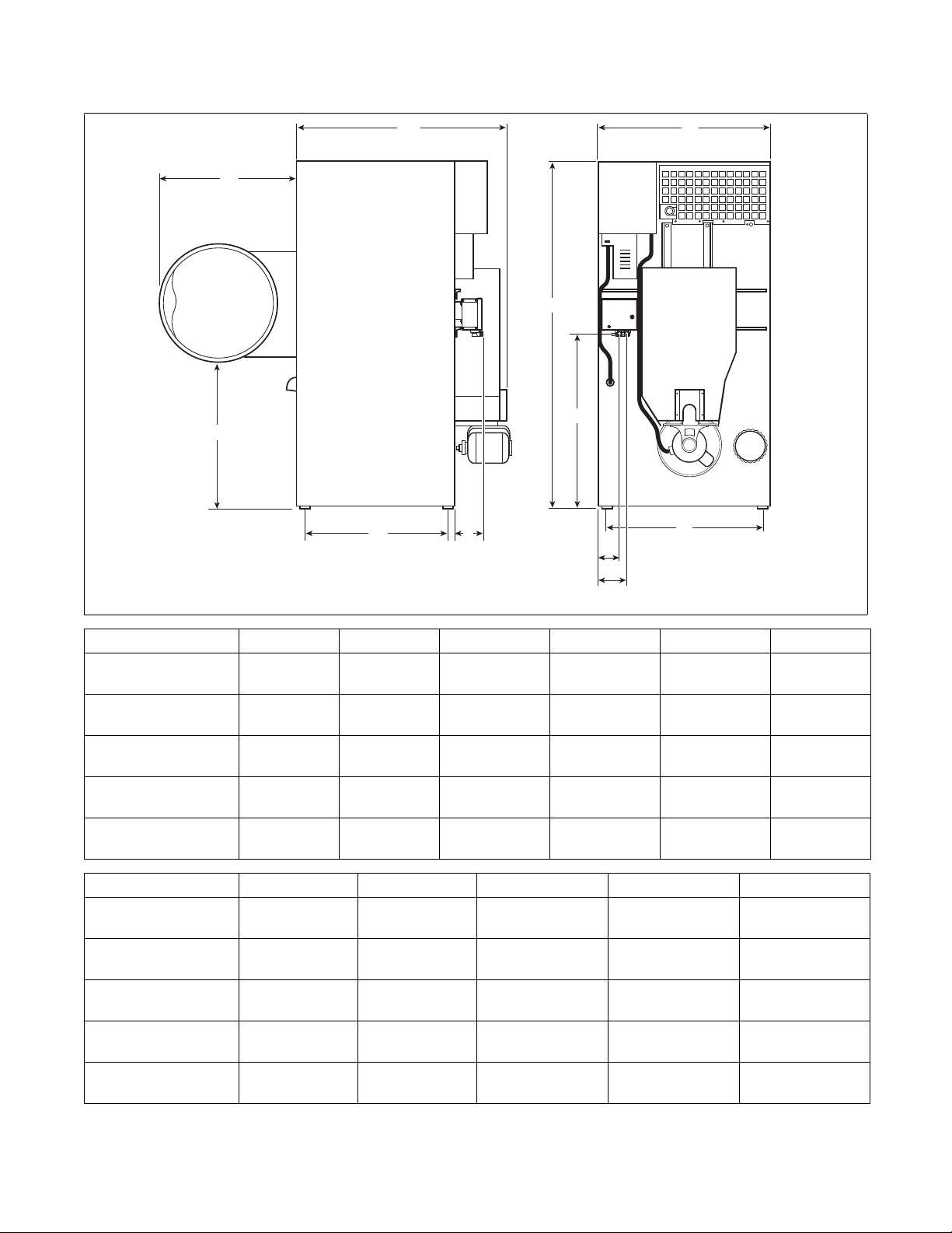
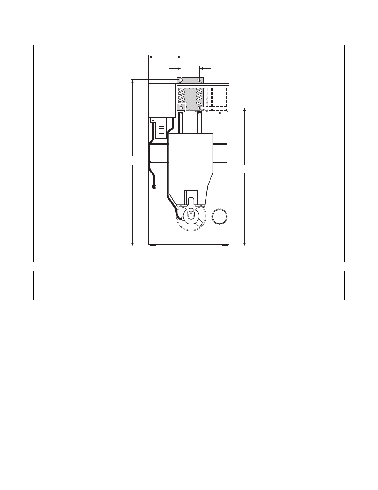
Specifications and Dimensions
TMB2293N
C
B
F
D
A
K
G
J
E
I
H
Cabinet Dimensions
Models A B C D E* F
50 Pound
Gas and Electric
50 Pound
Steam
75 Pound
Gas and Electric
75 Pound
Steam
F75
Gas
30.75 in.
(781 mm)
30.75 in.
(781 mm)
30.75 in.
(781 mm)
30.75 in.
(781 mm)
30.75 in.
(781 mm)
33.87 in.
(860 mm)
33.87 in.
(860 mm)
33.87 in.
(860 mm)
33.87 in.
(860 mm)
33.87 in.
(860 mm)
Models G H* I* J* K
50 Pound
Gas and Electric
50 Pound
Steam
75 Pound
Gas and Electric
75 Pound
Steam
F75
Gas
* Fire suppression system optional - may not be on machine.
33 in.
(838 mm)
33 in.
(838 mm)
33 in.
(838 mm)
33 in.
(838 mm)
33 in.
(838 mm)
7.1 in.
(180 mm)
7.1 in.
(180 mm)
7.1 in.
(180 mm)
7.1 in.
(180 mm)
7.1 in.
(180 mm)
48.25 in.
(1226 mm)
48.25 in.
(1226 mm)
54.25 in.
(1378 mm)
54.25 in.
(1378 mm)
54.25 in.
(1378 mm)
(140 mm)
(140 mm)
(140 mm)
(140 mm)
(140 mm)
5.5 in.
5.5 in.
5.5 in.
5.5 in.
5.5 in.
76.625 in.
(1946 mm)
80 in.
(2032 mm)
76.625 in.
(1946 mm)
80 in.
(2032 mm)
76.625 in.
(1946 mm)
(914 mm)
(914 mm)
(914 mm)
(914 mm)
(914 mm)
6.53 in.
(166 mm)
6.53 in.
(166 mm)
6.53 in.
(166 mm)
6.53 in.
(166 mm)
6.53 in.
(166 mm)
36 in.
36 in.
36 in.
36 in.
36 in.
TMB2293N
38.625 in.
(981 mm)
38.625 in.
(981 mm)
38.625 in.
(981 mm)
38.625 in.
(981 mm)
38.625 in.
(981 mm)
29.5 in.
(749 mm)
29.5 in.
(749 mm)
35.5 in.
(902 mm)
35.5 in.
(902 mm)
35.5 in.
(902 mm)
12
© Copyright, Alliance Laundry Systems LLC – DO NOT COPY or TRANSMIT
70420301 (EN)
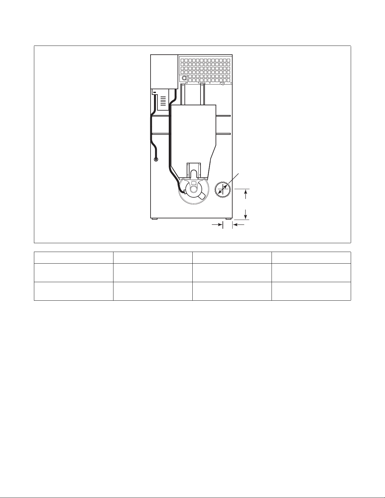
Exhaust Outlet Locations
A
B
C
Specifications and Dimensions
TMB2238N
ModelsABC
50/75 Pound
F75
5.375 in.
(137 mm)
6.5 in.
(165 mm)
8 in.
(203 mm)
10 in.
(254 mm)
13.375 in.
(340 mm)
6.5 in.
(165 mm)
70420301 (EN)
© Copyright, Alliance Laundry Systems LLC – DO NOT COPY or TRANSMIT
13
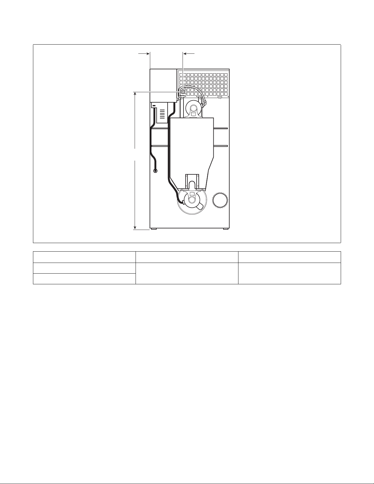
Specifications and Dimensions
A
B
Gas Connection Locations
Diameter A B
75 – 1/2 in. NPT 14.75 in.
F75 – 3/4 in. NPT
(375 mm)
TMB2239N
65.75 in.
(1670 mm)
14
© Copyright, Alliance Laundry Systems LLC – DO NOT COPY or TRANSMIT
70420301 (EN)
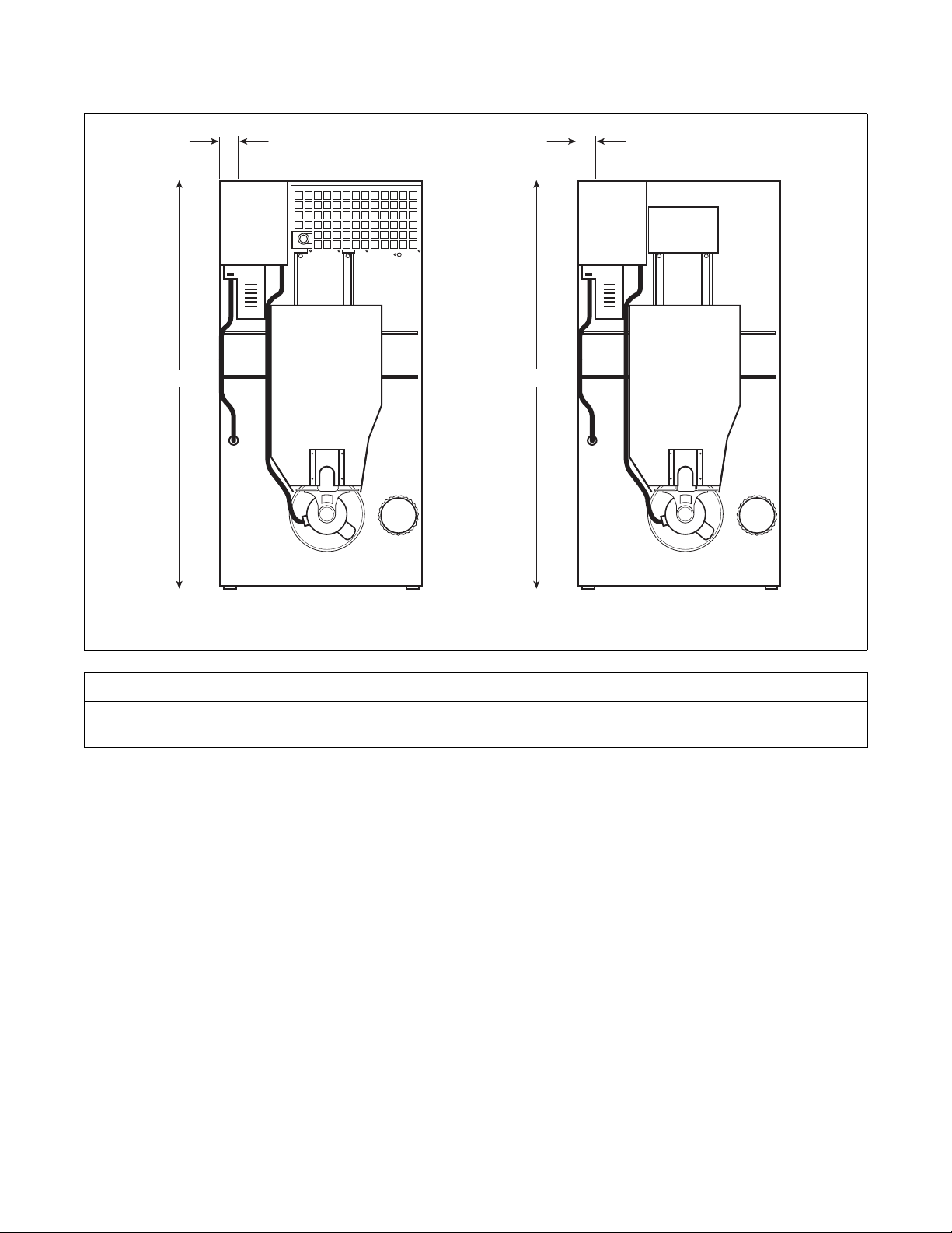
Electrical Connection Locations
GAS AND STEAM
ELECTRIC
A
A
B
B
Specifications and Dimensions
AB
3.25 in.
(83 mm)
NOTE: These figures are approximate dimensions only.
TMB2240N
75.5 in.
(1918 mm)
70420301 (EN)
© Copyright, Alliance Laundry Systems LLC – DO NOT COPY or TRANSMIT
15
Specifications and Dimensions
C
A
B
D
Steam Connection Locations
TMB2241N
ModelsDiameterABCD
50/75 Pound
3/4 in. NPT 15.5 in.
(394 mm)
78.25 in.
(1988 mm)
7.5 in.
(190 mm)
64.75 in.
(1645 mm)
16
© Copyright, Alliance Laundry Systems LLC – DO NOT COPY or TRANSMIT
70420301 (EN)

Installation
Pre-Installation Inspection
Upon delivery, visually inspect the crate, carton and
parts for any visible shipping damage. If the crate,
carton, or cover is damaged or signs of possible
damage are evident, have the carrier note the condition
on the shipping papers before the shipping receipt is
signed, or advise the carrier of the condition as soon as
it is discovered.
Remove the crate and protective cover as soon as
possible and check the items listed on the packing list.
Advise the carrier of any damaged or missing articles
as soon as possible. A written claim should be filed
with the carrier immediately if articles are damaged or
missing.
IMPORTANT: Remove the shipping tape from the
two back draft dampers located in the exhaust
outlet.
IMPORTANT: Warranty is void unless tumble
dryer is installed according to instructions in this
manual. Installation should comply with minimum
specifications and requirements detailed in this
manual and applicable local gas fitting regulations,
municipal building codes, water supply regulations,
electrical wiring regulations, and any other
relevant statutory regulations. Due to varied
requirements, applicable local codes should be
thoroughly understood and all pre-installation
work arranged for accordingly.
Materials Required (Obtain Locally)
One Single Pole fused disconnect
All Models
Gas Models
Steam Models
switch or circuit breaker on 1 Phase
models.
Circuit breaker on 3 Phase models.
One gas shut-off valve for gas service
line to each tumble dryer.
One steam shut-off valve for steam
service line to be connected upstream of
solenoid steam valve.
Two steam shut-off valves for each
condensate return line.
Flexible steam hoses with a 125 psig
(pounds per square inch gauge)
(8.79 kg/sq. cm) working pressure for
connecting steam coils. Refer to
Figure 22 for sizing and connection
configurations.
Two steam traps for steam coil outlets
to condensate return line.
Optional – Two vacuum breakers for
condensate return lines.
IMPORTANT: Keep tumble dryer area clear and
free from combustible materials, gasoline and other
flammable vapors and liquids.
NOTE: 3 Phase Only – Each tumble dryer must be
connected to its own individual branch circuit
breaker, not fuses, to avoid the possibility of “single
phasing” and causing premature failure of the
motor(s).
70420301 (EN)
© Copyright, Alliance Laundry Systems LLC – DO NOT COPY or TRANSMIT
17
 Loading...