

Alliance Laundry Systems ATEE9AWP433AW01, FTEE5ASP303ZW01, BTGE6ASP113TW01, FTEE5ASP303NW10, FTGE5ASP303NW10 Troubleshooting Manual
...
Homestyle
SWD456C
Stacked Washer/
Dryers
Refer to Page 6 for Model Numbers
Troubleshooting
SWD456C

Table of
Section 1 – Safety Information ...............................................................3
Locating an Authorized Servicer...........................................................4
Contents
Section 2 – Introduction ..........................................................................5
Customer Service...................................................................................5
Nameplate Location...............................................................................5
Model Identification ..............................................................................6
Theory of Operation ..............................................................................7
Section 3 – General Troubleshooting.....................................................8
1. Keypad Combinations...................................................................8
2. Factory Test Procedure ...............................................................10
3. Motor Circuit...............................................................................16
4. Dipswitch Configuration.............................................................17
5. Troubleshooting Knocking Noise ...............................................18
6. Explanation of LEDs on Drive Control ......................................18
7. Door Fails to Unlock at End of Cycle.........................................18
8. No Spin .......................................................................................18
9. Excessive Vibration and/or Noise During Spin..........................20
10. Excessive Cycle Time.................................................................21
Section 4 – Dryer Control Troubleshooting ........................................22
7. Dryer Error Code Listing ............................................................22
8. Dryer Motor Does Not Run ........................................................24
9. Dryer Stops in Cycle; Quits After the First Few Loads;
Has a Burning Smell; Cycles On Motor Thermal Protector .......26
10. Dryer Motor Runs But Cylinder Does Not Turn ........................27
11. Dryer Motor Does Not Stop .......................................................28
12. Dryer Runs Only When Door is Open ........................................29
13. Dryer Heating Assembly Does Not Heat or
Burner Does Not Ignite...............................................................30
14. Igniter Does Not Glow (Gas Supply Sufficient)
– Gas Dryer Models ....................................................................32
15. Burner Ignites and Goes Out Repeatedly
– Gas Dryer Models ....................................................................33
16. Igniter Glows But Burner Does Not Ignite
– Gas Dryer Models ....................................................................34
17. Dryer Heater Assembly or Burner Shuts Off Prematurely .........35
18. Dryer Heater Assembly or Burner Repeatedly Cycles
Off On Limit Thermostat ............................................................36
19. Dryer Heater Assembly or Burner Does Not Shut Off ...............38
20. Clothes Do Not Dry in Dryer......................................................39
21. Timer Does Not Advance in Automatic Cycle ...........................40
22. Clothes Are Too Hot When Removed From Dryer ....................41
23. Excessive Chattering or Vibrating Noise in Dryer .....................42
24. Excessive Humming or Whistling Noise in Dryer......................43
1

Section 5 – Washer Control Troubleshooting.....................................44
25. Error Codes .................................................................................44
26. No keypad Function ....................................................................51
27. No Visible Display on Control....................................................52
28. Washer Will Not Start – “do” Displayed....................................54
29. Washer Will Not Start – “Er”, “dl” on Display ..........................56
30. Washer Will Not Fill (Machine Empty,
No “Er”, “PS” on Display)..........................................................58
31. Washer Overflows.......................................................................60
32. Pump or Drain Valve Does Not Operate ....................................62
33. Motor Does Not Run (“Ed”, “29” on Display) ...........................64
34. Washer Will Not Heat (Models Equipped with Heater)
(“Er”, “oP” or “Er”, “SH” Displayed) ........................................66
35. Washer Will Not Heat (Models Equipped with Heater) .............68
Section 6 – Adjustments ........................................................................70
36. Cabinet Leveling Legs ................................................................70
37. Washer Loading Door.................................................................71
38. Washer Motor Belt Tension........................................................72
39. Washer Door Catch.....................................................................73
40. Shipping Braces ..........................................................................75
41. Burner Flame (Gas Models)........................................................76
Section 7 – Dryer Test Procedures .......................................................77
42. Timer Contacts............................................................................77
43. Fabric Selector Switch ................................................................78
44. Drive Motor.................................................................................79
45. Motor Switch...............................................................................82
46. Burner System Operation............................................................84
47. Electrical Circuit To Ignition System (Gas Models) ..................85
48. Gas Valve Coils Check (Gas Models) ........................................85
49. Sensor Check (Gas Models)........................................................86
50. Igniter Check (Gas Models)........................................................86
51. Thermal Fuse (Electric Models) .................................................87
52. Heater Assembly (Electric Models)............................................87
53. Cycling or Limit Thermostat.......................................................87
54. Door Switch ................................................................................88
Section 8 – Internal Wiring of Dryer Motor Switch...........................89
Section 9 – Cycle Sequence Charts.......................................................90
2 806221
Section 1
• Failure to install, maintain, and/or operate this machine according to the manufacturer’s
instructions may result in conditions which can produce serious injury, death and/or
property damage.
• Do not repair or replace any part of the machine or attempt any servicing unless specifically
recommended or published in this Service Manual and that you understand and have the
skills to carry out.
• Whenever ground wires are removed during servicing, these ground wires must be
reconnected to ensure that the machine is properly grounded and to reduce the risk of fire,
electric shock, serious injury, or death.
W284
WARNING
Safety Information
Throughout this manual and on machine decals, you will find precautionary statements (“CAUTION,”
“WARNING” and “DANGER”) followed by specific instructions. These precautions are intended for the personal
safety of the operator, user, servicer, and those maintaining the machine.
DANGER
Danger indicates an imminently hazardous situation that, if not avoided, will cause severe personal injury or death.
WARNING
Warning indicates a hazardous situation that, if not avoided, could cause severe personal injury or death.
CAUTION
Caution indicates a hazardous situation that, if not avoided, may cause minor or moderate personal injury or property
damage.
Additional precautionary statements (“IMPORTANT” and “NOTE”) are followed by specific instructions.
IMPORTANT
The word “IMPORTANT” is used to inform the reader of specific procedures where minor machine damage will
occur if the procedure is not followed.
NOTE
The word “NOTE” is used to communicate installation, operation, maintenance or servicing information that is
important but not hazard related.
In the interest of safety, some general precautions relating to the operation of this machine follow.
806221 3
Safety Information
To reduce the risk of electric shock, fire, explosion, serious injury or death:
• Disconnect all electric power to the machine and accessories before servicing.
• Close gas shut-off valve to gas dryer before servicing.
• Never start machine with any guards/panels removed.
• Whenever ground wires are removed during servicing, these ground wires must be
re
connected to ensure that the machine is properly grounded.
• Washer motor not grounded! Disconnect electric power before servicing motor.
W502
WARNING
Repairs that are made to your products by unqualified persons can result in hazards due to
improper assembly or adjustments subjecting you, or the inexperienced person making such
repairs, to the risk of serious injury, electrical shock, or death.
W007
WARNING
If you or an unqualified person perform service on your machine, you must assume the
responsibility for any personal injury or property damage which may result. The manufacturer
will not be responsible for any injury or property damage arising from improper service and/or
service procedures.
W286
WARNING
NOTE: The WARNINGS and IMPORTANT INSTRUCTIONS appearing in this manual are not meant to
cover all possible conditions and situations that may occur. Common sense, caution and care must be
exercised when installing, maintaining or operating the machine.
Always contact your dealer, distributor, service agent or the manufacturer about any problems or conditions you do
not understand.
Locating an Authorized Servicer
Alliance Laundry Systems is not responsible for personal injury or property damage resulting from improper
service. Review all service information before beginning repairs.
Warranty service must be performed by an authorized technician, using authorized factory parts. If service is
required after the warranty expires, Alliance Laundry Systems also recommends contacting an authorized technician
and using authorized factory parts.
4 806221

Section 2
SWD1716S
Nameplate
Nameplate
SWD1716S
Introduction
Nameplate Location
When calling or writing about your product, be sure to
mention model and serial numbers. Model and serial
numbers are located on nameplate(s) as shown.
806221 5

Introduction
Model Identification
Information in this manual is applicable to these models.
ATEE9AWP433AW01
ATGE9AWP303AW01
BTEE6ASP173TW01
BTEE6ASP283CW01
BTGE6ASP093CW01
BTGE6ASP113TW01
FTEE5ASP303NW10
FTEE5ASP303ZW01
FTGE5ASP303NW10
LTEE5ASP153TW01
LTEE5ASP173TW01
LTEE5ASP293CW01
LTEE5ASP303ZW01
LTEE5ASP333NW01
LTEE5ASP433AW01
LTEE5ASP433AW12
LTEE5ASP543NW23
LTGE5ASP113JW01
LTGE5ASP113TW01
LTGE5ASP303AW01
LTGE5ASP303AW12
LTLE5ASP543NW23
UTEE5ASP173TW01
UTEE5ASP173TW08
UTEE5ASP283CW01
UTGE5ASP113TW01
UTGE5ASP113TW08
YTEE5ASP173TW01
YTEE5ASP283CW01
YTGE5ASP093CW01
YTGE5ASP113TW01
6 806221

Introduction
Theory of Operation
General (Dryer)
The dryer uses heated air to dry loads of laundry.
When the motor is started, the exhaust fan pulls fresh
air in through louvers at the rear of the dryer and over
the heat source (burner flame for gas and heating
element for electric). The heated air moves through the
heater duct and into the cylinder, where it circulates
through the wet load. The air then passes through the
lint filter, air duct and exhaust fan, where it is vented
to the outdoors.
General (Washer)
This frontload washer provides some of the same
principles of operation as the typical topload washers.
It senses water level, it dispenses the desired laundry
detergent, agitates the clothes for good cleaning action,
removes the water out of the washer and spins the
clothing in preparation for the dryer.
The difference in operation is primarily the rotational
washing agitation created for the horizontal basket and
drum. This agitation tumbles the clothes in a clockwise,
pause, and counter-clockwise direction. This reversing
tumbling action provides an efficient washing process
and requires less laundry detergent and less water.
The cycle begins by locking the loading door after the
vend is satisfied. The type of cycle and water
temperature are determined by the appropriate pads on
the electronic control.
The inner basket starts agitating during the wash water
fill. A column of air is trapped in a pressure bulb and
hose. The air pressure continues to increase as the inner
basket fills with water with the pressure sensor
monitoring the water level.
The agitate step tumbles the clothing in a clockwise
direction for a period of time, pauses for a period of
time and then tumbles the clothing in a
counterclockwise direction for a period of time. This
agitation continues until the end of the wash cycle. The
machine then stops agitating and turns on the pump or
drain valve which removes the wash water.
After all the rinse cycles have been completed, the
washer goes into a final spin cycle to extract as much
water as possible from the clothing to prepare them for
the dryer. The spin speeds and duration of this final
spin cycle are determined by the type of wash cycle
selected.
NOTE: Washer may not reach 1200 RPM because
of an out-of-balance condition. Control may limit
speed to 1000, 800, 650 or 500 RPM depending on
severity of out-of-balance condition.
Technical (Washer)
The basic operational system of this washer consists of
the electronic control, the inverter control, pressure
sensor, water valves, electric pump (or drain valve)
and A.C. motor.
The electronic control performs all control and timing
functions. The electronic control sends simple speed
and output commands to the inverter control via serial
communication. The drive control powers the door
lock, pump (or drain valve), motor, water valves and
heater (if equipped).
The drive control powers the A.C. motor and performs
all motor control functions. The drive control also
powers the water valves, dispenser valves and door
lock. The drive control is powered through the door
switch and electronic control. The drive control also
alerts the electronic control to any errors in the motor.
Before entering any spin step the drive control
measures out-of-balance. The drive control will try to
redistribute the clothes if an out-of-balance condition
exists by limiting the spin speed to several speeds
depending on the severity of the out-of-balance
condition. If the out-of-balance condition is severe
enough the drive control will limit speed to 90 RPM
and will not spin.
NOTE: An additional out-of-balance switch is used
to detect any out-of-balance condition during spins.
If this switch opens during a spin step, the drive
control immediately stops and then restarts the
spin.
Upon completion of the wash cycle, the machine goes
into a rinse cycle. Fresh cold water is brought into the
inner basket via the mixing valve until the fill level is
satisfied. The rinse cycle consists of agitation for a
predetermined amount of time then a spin mode with
the pump running where the machine goes into a series
of spins.
806221 7
General Troubleshooting
To reduce the risk of electric shock, fire, explosion, serious injury or death:
• Disconnect electric power to the washer before servicing.
• Never start the washer with any guards/panels removed.
• Whenever ground wires are removed during servicing, these ground wires must
be
re
connected to ensure that the washer is properly grounded.
• Motor not grounded! Disconnect electric power before servicing motor.
W485
WARNING
FLW1815S
1
2
3
5
6
7
8
9
10
11
12
16
17
21
28
22
23
26 27
25
24
13 18
14 19
15 204
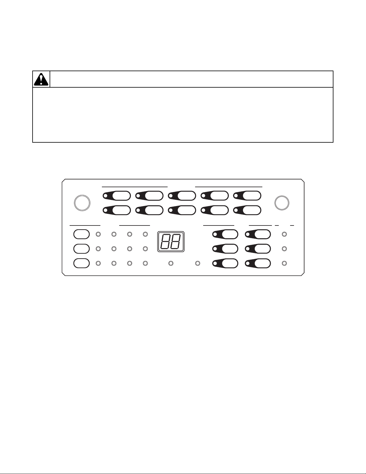
1. Keypad Combinations
Section 3
Figure 1
8 806221
General Troubleshooting
To reduce the risk of electric shock, fire, explosion, serious injury or death:
• Disconnect electric power to the washer before servicing.
• Never start the washer with any guards/panels removed.
• Whenever ground wires are removed during servicing, these ground wires must
be
re
connected to ensure that the washer is properly grounded.
• Motor not grounded! Disconnect electric power before servicing motor.
W485
WARNING
Testing Mode Keypad Entry
Function Keys Entry State
Enter/Exit Software Version Display Mode 7+8 Start Mode
Turn On/Off Rainbow Pizzazz Display 9+10 Start Mode
Toggle Keypad Acknowledgement 13+14 Start Mode
Toggle Suds Extra Time Mode 2+3 Start Mode and powered for less than 5 minutes
Enter Factory Test Mode 2+7 Start Mode and powered for less than 5 minutes
Enter/Exit Audit Display Mode 3+9 Start Mode
Enter/Exit Factory Test Counter Display Mode 2+9 Start Mode
Enter/Exit Show Mode 3+8 Start Mode
Enter/Exit Extra Water Mode 8+14 Start Mode and Default/Extra Water Dipswitch On
Enter/Exit Drive Version Display Mode 3+14 Start Mode
Rapid Advance Through Current Cycle Step 7+13 Run Mode
Enter/Exit Spin Retry Extra Time Toggle Mode 8+ 13 Start Mode and powered for less than 5 minutes.
Enter/Exit Water Level Display Mode 4+14 Any Mode except if Control Lock is On
Table 1
Water Level Display Mode
The control will read the current water level. The
display will show the water level least significant digits
in 0.1 inch precision which will override any other
display.
If the water level is a negative value, then the right most
decimal point is lit. If the value is greater than or equal
to 10.0 inches, LED number 28 will be lit. If the value
will be lit. If the value is greater than or equal to 30.0
inches, LEDs 28, 22 and 23 will be lit.
To exit this mode, the user can either press the two keys
used to enter this mode, press the Power/Cancel key, or
unplug the machine. This mode only overrides the
display, the machine will continue running any other
modes that it is in.
is greater than or equal to 20.0 inches, LEDs 28 and 22
Value Display # 28 Light On? # 22 Light On? # 23 Light On?
4.5 inches 45 No No No
-3.2 inches 32. No No No
12.4 inches 24 Yes No No
20.8 inches 08 Yes Yes No
42.9 inches 29 Yes Yes Yes
Tab l e 2
806221 9

General Troubleshooting
To reduce the risk of electric shock, fire, explosion, serious injury or death:
• Disconnect electric power to the washer before servicing.
• Never start the washer with any guards/panels removed.
• Whenever ground wires are removed during servicing, these ground wires must be
reconnected to ensure that the washer is properly grounded.
• Motor not grounded! Disconnect electric power before servicing motor.
W485
WARNING
2. Factory Test Procedure
It is helpful to run the Factor Test Procedure first to
diagnose the machine’s issue. This procedure tests all
machine features and operations.
To Enter Factory Test Procedure
1. Be certain control is in Start Mode and less than
5 minutes after powering control.
2. Press keypads numbered 2 and 7 at the same time.
Refer to Figure 1.
3. When the control enters the Factory Test
Procedure, it will display the first test step,
Machine
4. To advance through the sequence of test step
press the Start/Pause keypad (No. 21). Refer to
Tabl e 3 for all tests in the Factory Test Procedure.
Type.
To Exit Factory Test Procedure
To exit the Factory Test Procedure, refer to Exit
column in Tabl e 3.
Factory Test Procedure Quick Reference Chart
NOTE: ES refers to the External Supply Outputs.
# Display
0 FL None Off None Unlocked Off Open 1 Control Type
1 XX None Off None Unlocked Off Open 1
2 HX None Off None Unlocked Off Open 1 Control Level
3 XX None Off None Unlocked Off Open 1
4 XX None Off None Unlocked Off Open 1
Status
LEDs Lit
Motor Valves Door Pump Dump Exit* Step
Software
Ve r s i o n #
Dipswitch Value
Display
Cycle
Configuration
s
Refer to
5PX
688
dO with door
7
10 806221
open
dC with door
closed
Keypad
Test
section
All plus
audio
signal on
high
None Off None Unlocked Off Open
Off None Unlocked Off Open 3 Keypad Test
Off None Unlocked Off Open 1 Show Mode
Table 3 (continued)
10
And
Then
1
Door Switch Test

To reduce the risk of electric shock, fire, explosion, serious injury or death:
• Disconnect electric power to the washer before servicing.
• Never start the washer with any guards/panels removed.
• Whenever ground wires are removed during servicing, these ground wires must
be
re
connected to ensure that the washer is properly grounded.
• Motor not grounded! Disconnect electric power before servicing motor.
W485
WARNING
Table 3 (continued)
# Display
Status
LEDs Lit
Motor Valves Door Pump Dump Exit* Step
8 db None Off None Unlocked Off Open
9 XX None Off None Unlocked Off Open
General Troubleshooting
10, 12
And
Then
Drive Type
1
10, 12
And
Then
Drive Version #
1
dL when door
10
locks
dU when door
None Off None Locked Off Open1And
unlocks
Cold,
11 Cd Wash Off
Detergent,
Locked Off Closed 1
ES 1
Hot,
12 HS Wash Off
Softener,
Locked Off Closed 1
ES 2
13 PS Wash Off Hot, Cold Locked Off Closed
14 XX None Off None Locked Off Closed 1 Or 5 Heater Test
Hot, Cold,
Detergent,
Softener,
15 OF Wash Off
ES
Locked Off Closed
1, 2, 3, 4,
Cycle
Output
ES 3,
Cycle
Locked Off Closed 1 Low Agitate
Output
ES 4 Locked Off Closed 1 Regular Agitate
Table 3 (continued)
16 LA Rinse
17 rA Rinse
Low
Agitate
Regular
Agitate
806221 11
2 And
Then
8 And
Then
Door Lock Check
7
Cold, Detergent,
Output 1
Hot, Softener,
Output 2
Pressure Sensor
1
Overflow
1
Test
Fill
General Troubleshooting
To reduce the risk of electric shock, fire, explosion, serious injury or death:
• Disconnect electric power to the washer before servicing.
• Never start the washer with any guards/panels removed.
• Whenever ground wires are removed during servicing, these ground wires must
be
re
connected to ensure that the washer is properly grounded.
• Motor not grounded! Disconnect electric power before servicing motor.
W485
WARNING
# Display
Status
LEDs Lit
Pu for pump
18
installed
dr for gravity
Rinse Off None Locked On Open 9
drain installed
19 actual RPM Spin
Table 3 (continued)
Motor Valves Door Pump Dump Exit* Step
Pump/Gravity
Drain
Fac-
tory
Spin
None Locked On Open 1 Factory Spin
Profile
20 bA Spin
Break-
away
Agitate
Hot, Cold,
Detergent,
Softener,
ES
1, 2, 3, 4,
Cycle
Output
Unlocked On Open
1, 1
Again
Then
4
Then
11
Breakaway
21 Pd Spin Off None Unlocked Off Open 13 Power Down
Tab l e 3
EXIT column key:
1-exit by Start/Pause keypress
2-exit by fill level satisfaction
3-exit when all keypads are pressed
4-exit when door is unlocked
5-exit when temp reaches 40
°C
6-exit when step timed out
7-exit when door locks
8-exit when overflow level reached
9-exit when drum is empty
10-exit when door is closed
11-exit when door is opened
12-exit when drive communication is established
13-exit when machine unpowered
12 806221
To reduce the risk of electric shock, fire, explosion, serious injury or death:
• Disconnect electric power to the washer before servicing.
• Never start the washer with any guards/panels removed.
• Whenever ground wires are removed during servicing, these ground wires must
be
re
connected to ensure that the washer is properly grounded.
• Motor not grounded! Disconnect electric power before servicing motor.
W485
WARNING
Keypad Test
General Troubleshooting
Upon entry into this test, the control will display “P-”.
When a keypad is pressed the control will display “PX”
where X is the keypad number referenced in Tabl e 4.
For keypads 10 and greater the control will display
“XX” where XX is the keypad number. As each
keypad is pressed, the nearest LED
will light up and remain lit for the duration of the
keypad test. When all keypads have been pressed the
control will automatically advance to the next step.
Keypads that are not available on some controls do not
need to be tested. Refer to Figure 1 for keypad number
and LED references.
Keypad Numbers (some models may not have all keypads)
Display Key Number LED
P1
P2
P3 3 25
P4 4 24
P5 5 Next to keypad
P6 6 Next to keypad
P7 7 Next to keypad
P8 8 Next to keypad
P9 9 Next to keypad
10 10 Next to keypad
13 11 Next to keypad
1 22
2 26
14 12 Next to keypad
15 13 Next to keypad
16 14 Next to keypad
17 15 Next to keypad
18 16 Next to keypad
19 17 Next to keypad
20 18 Next to keypad
21 19 Next to keypad
22 20 Next to keypad
23 21 23
Tab l e 4
806221 13
General Troubleshooting
To reduce the risk of electric shock, fire, explosion, serious injury or death:
• Disconnect electric power to the washer before servicing.
• Never start the washer with any guards/panels removed.
• Whenever ground wires are removed during servicing, these ground wires must
be
re
connected to ensure that the washer is properly grounded.
• Motor not grounded! Disconnect electric power before servicing motor.
W485
WARNING
Dipswitch Value Display Test
This step displays the state of the Control
Configuration Dip Switches in hex, where the least
significant bit is Dip Switch #1 and the most significant
bit is Dip Switch # 8.
If a dipswitch is set to ON, the corresponding bit is set
to 1, otherwise if the dipswitch is set to OFF, the bit is
set to 0. The most common configurations are listed in
Tabl e 5.
Dipswitch Value Display
Machine Configuration Value
120 Volt with Electric Pump 00
120 Volt with Gravity Drain 80
240 Volt with Electric Pump 01
240 Volt with Gravity Drain 81
240 Volt Heater Machine with Electric Pump and Cool Down Enabled 61
240 Volt Heater Machine with Gravity Drain and Cool Down Enabled E1
Table 5
Cycle Configuration Test
This step verifies which set of cycles are used.
Cycle Configuration Display
Cycle Set Models Display
Default With “T” and “C” in the 12
Australia With “A” in the 12
th
character of the model number “dE”
th
character of the model number “AU”
International All Other models “in”
Tab l e 6
Cold/Detergent Fill
This step checks the cold water valve and the detergent/
bleach valve. The cold water fill valve, the detergent/
bleach valve and the External Supply Valve 1 turn on.
The valves will shut off once a low fill level is reached.
Pressure Sensor Fill
This step checks the analog water level input. When the
water fill level is satisfied, the water valves are turned
off. The control will not advance to the next step until
the normal fill level is satisfied.
Hot/Softener Fill
This step checks the hot water valve and the softener
valve. The hot water fill valve, the softener valve and
the External Supply Valve 2 turn on. The valves will
shut off once a medium fill level is reached.
14 806221

General Troubleshooting
To reduce the risk of electric shock, fire, explosion, serious injury or death:
• Disconnect electric power to the washer before servicing.
• Never start the washer with any guards/panels removed.
• Whenever ground wires are removed during servicing, these ground wires must
be
re
connected to ensure that the washer is properly grounded.
• Motor not grounded! Disconnect electric power before servicing motor.
W485
WARNING
Heater (Heater Models Only)
This step checks the heater operation. The display
shows “xx”, where xx is the temperature in degrees
Celcius. The control will heat the water to 40 degrees
Celcius while displaying the temperature as it rises at a
rate of 1 degree. If the temperature sensor is open or
shorted, the display will show “Er” and “OP” or “SH”.
Overflow Test
This test checks the overflow setting for the water level
sensor. When the overflow level is reached, the water
valves, all External Supply Valves and the Cycle Run
Output will automatically turn off. The control will not
advance to the next step until the overflow level is
satisfied.
Low Agitate
This step checks the Low Agitate speed. The display
shows “LA”, the Rinse LED is on, the Auxiliary Output
3 is on, Cycle Run Output is on, and the machine enters
a low agitate. The control will remain in this mode until
the Start/Pause keypad is pressed.
Regular Agitate
This step checks the Regular Agitate speed. The
display shows “rA”, the Rinse LED is on, the Auxiliary
Output 4 is on, and the machine enters a regular agitate.
The control will remain in this mode until the Start/
Pause keypad is pressed.
Pump/Gravity Drain Test
This step checks the Pump output. The display shows
“Pu” for an electric pump or “dr” for a gravity drain,
the Rinse LED is on, and the Pump is turned on or the
Gravity Drain is opened. The control will only advance
to the next test step after the Water Level Sensor
indicates that the drum is empty.
Factory Spin
This step checks the spin speeds. The display shows the
most significant two digits of the actual RPM.
806221 15
The machine steps through spin speeds and maintains
each speed for a few seconds. After 1200 RPMs, the
motor will stop.This step lasts 4 minutes. All Out of
Balance checking is done and if either the out of
balance switch is hit or the OBL check fails and needs
to re-spin, the time will be reset indefinitely to allow
the load to be rebalanced so that it can spin up and reach
full speed. The control will advance to the next step if
the Start/Pause keypad is pressed at any time during
this step.
During this step if 800 RPMs is reached, LED number
26 will be lit. If 1000 RPMs is reached, the LED
number 25 will be lit. If 1200 RPMs is reached, the
LED number 24 will be lit, and if 1100 RPMs is
reached, the LED number 27 will be lit to indicate that
a passing speed has been reached. Refer to Figure 1 for
LED number definition.
Breakaway
This step checks the breakaway speed and the door
unlock function. All valves will be open at the
beginning of this step to allow the blowing out of the
valves by the factory. The Start/Pause keypad must be
pressed to start exiting the test. The first Start/Pause
keypress will turn off the water valves, the second
Start/Pause keypress will stop the motor and start the
unlock process. The third Start/Pause keypress will
start the unlock process. Once the door unlocks, it
needs to be opened to finally exit the test. The water
level sensor will be trimmed in this step after a 20
second delay and once the Start/Pause key is pressed
the first time.
During this step the LEDs for indicating speeds
reached from the Factory Spin step will remain lit in
this step.
Power Down
This is the final step of factory test procedure. The
control will display “Pd” to signify that the procedure
has been completed and that the user can safely unplug
the machine. Cycling power to the machine is the only
way to resume normal operation.
General Troubleshooting
To reduce the risk of electric shock, fire, explosion, serious injury or death:
• Disconnect electric power to the washer before servicing.
• Never start the washer with any guards/panels removed.
• Whenever ground wires are removed during servicing, these ground wires must
be
re
connected to ensure that the washer is properly grounded.
• Motor not grounded! Disconnect electric power before servicing motor.
W485
WARNING
FLW1792S
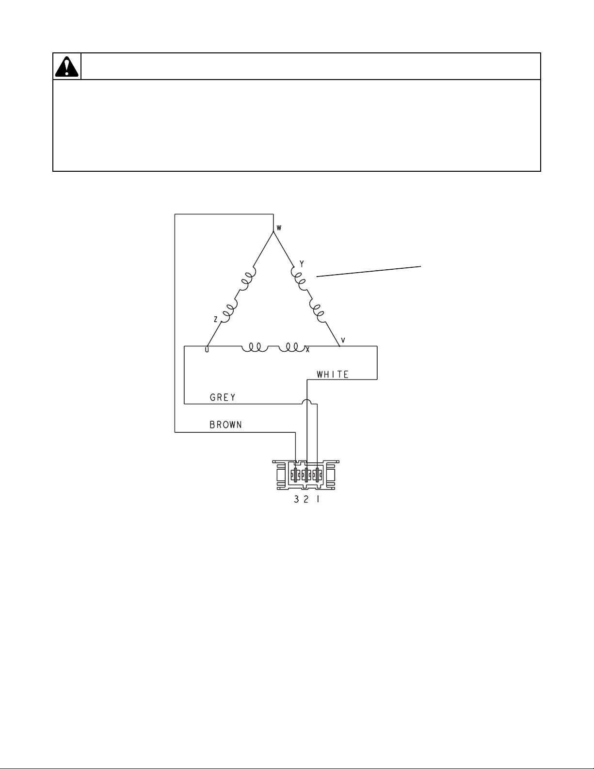
Windings
FLW1792S
3. Motor Circuit
Windings Resistance:
Approx. 3.38 ohms
16 806221
General Troubleshooting
To reduce the risk of electric shock, fire, explosion, serious injury or death:
• Disconnect electric power to the washer before servicing.
• Never start the washer with any guards/panels removed.
• Whenever ground wires are removed during servicing, these ground wires must
be
re
connected to ensure that the washer is properly grounded.
• Motor not grounded! Disconnect electric power before servicing motor.
W485
WARNING
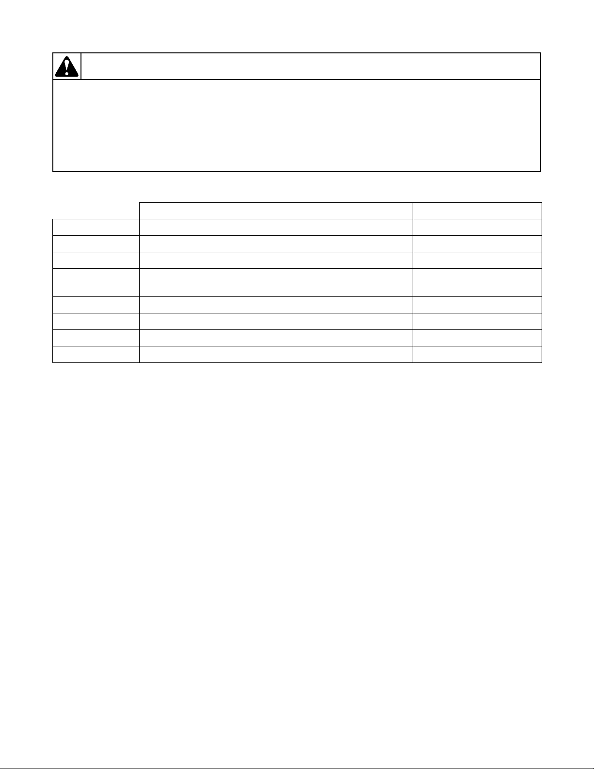
4. Dipswitch Configuration
OFF ON
Switch 1 120 Volt AC Supply 240 Volt AC Supply
Switch 2* Energy Saving Cycles Standard Cycles
Switch 3** Default Water Level Increased Water Level
Switch 4
Switch 5 Unused Unused
Switch 6 Cool Down Disabled Cool Down Enabled
Switch 7 Heater Disabled Heater Enabled
Leak and Slow Drain Errors Off
Leak and Slow Drain Errors
On
Switch 8 Electric Pump Gravity Drain
Tab l e 7
*Switch 2
When set to OFF, energy saving water and fill levels are used for the specific type/region of the machine. When set
to ON, energy saving cycle settings are not used.
**Switch 3
When set to OFF, the Default Water Levels are used. When set to ON, the owner can increase the water level using
the Extra Water Mode. Higher water levels are not recommended as they may result in water leaking from the
machine door.
806221 17
General Troubleshooting
To reduce the risk of electric shock, fire, explosion, serious injury or death:
• Disconnect electric power to the washer before servicing.
• Never start the washer with any guards/panels removed.
• Whenever ground wires are removed during servicing, these ground wires must
be
re
connected to ensure that the washer is properly grounded.
• Motor not grounded! Disconnect electric power before servicing motor.
W485
WARNING
FLW1814S
1
4
3
2
5. Troubleshooting Knocking Noise
If a frontload washer produces a noise similar to a
kn
ock on a door, it might be due to a flat spot on
the belt. The knocking sound is made when
flat spo
during a ramp spin and fade after reaching a
higher RPM.
To correct this condition, replace the belt.
t hits the pulley. The knocking may occu
the
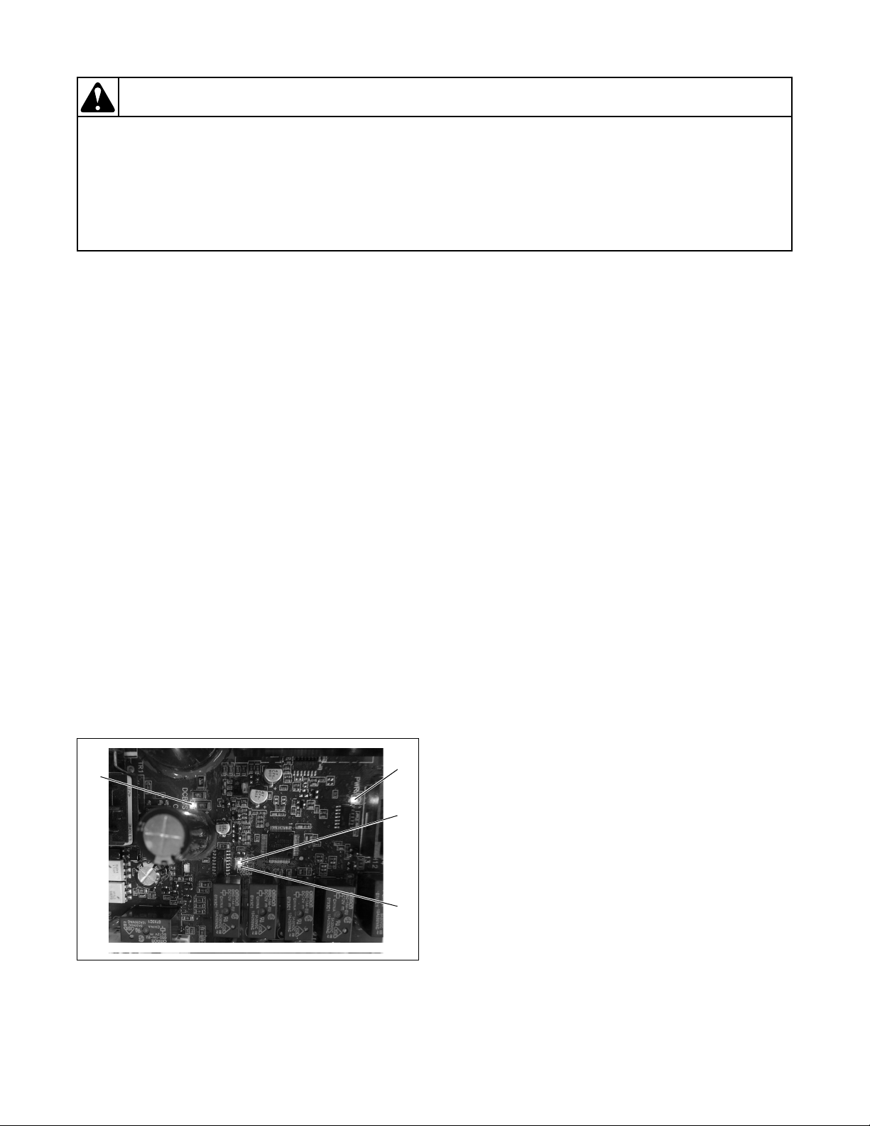
6. Explanation of LEDs on Drive Control
There are four LEDs on the control to assist with
troubleshooting (refer to Figure 2):
1. Green LED on constant = 5VDC power supp
sent
pre
2. Green LED flashing one second on/one second
off = drive control is active
3. Red LED flashing = drive contro
co
mmunicating with front end control
4. Red LED on constant = DC Bus Charged
NOTE: Drive is only powered when door is closed
and front end control turns it on.
l is
ly
7. Door Fails to Unlock at End of Cycle
If the door won’t unlock at the end of the cycle and the
r
cycle time is flashing in the display, the water might be
too hot to drain. Add a cool-down step to the cycle to
make sure the water will be cooled. Enable the cooldown feature by setting the cool down dip switch (#6)
to ON.
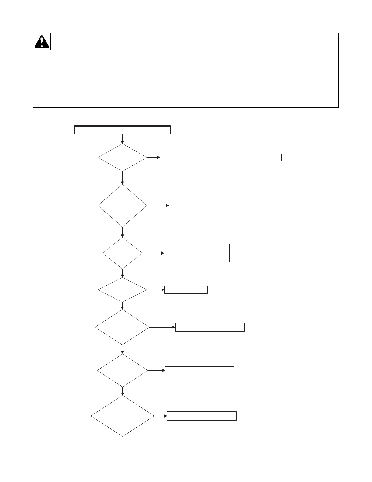
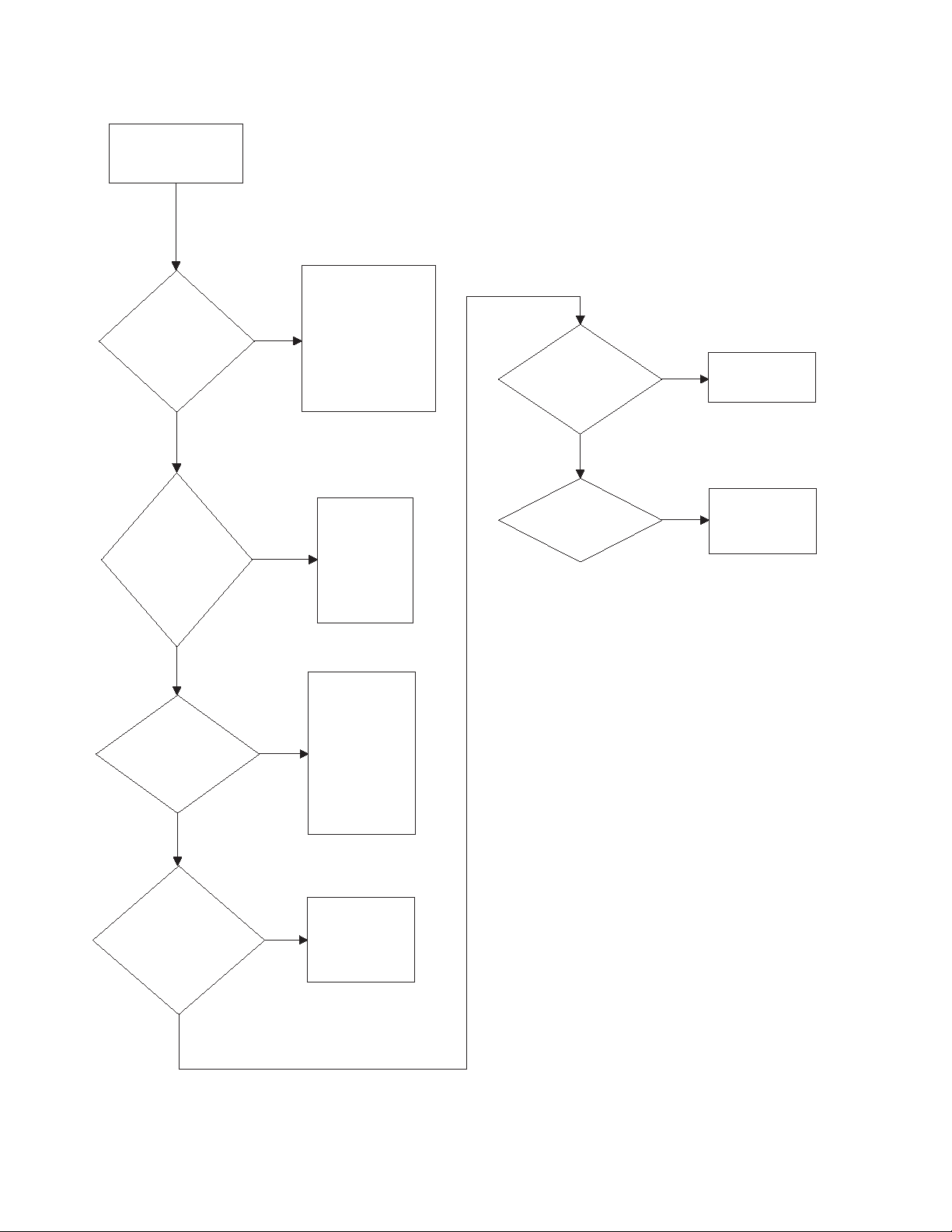
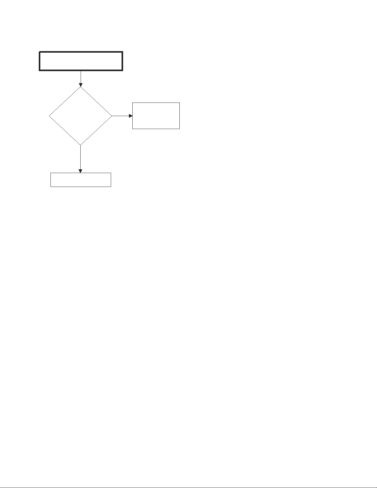
8. No Spin
A no spin condition is not caused by intermittent
operation of the motor or motor control (inverter
assembly). DO NOT replace these components for no
spin complaints if the unit passes the following
procedure:
Figure 2
18 806221
To reduce the risk of electric shock, fire, explosion, serious injury or death:
• Disconnect electric power to the washer before servicing.
• Never start the washer with any guards/panels removed.
• Whenever ground wires are removed during servicing, these ground wires must
be
re
connected to ensure that the washer is properly grounded.
• Motor not grounded! Disconnect electric power before servicing motor.
W485
WARNING
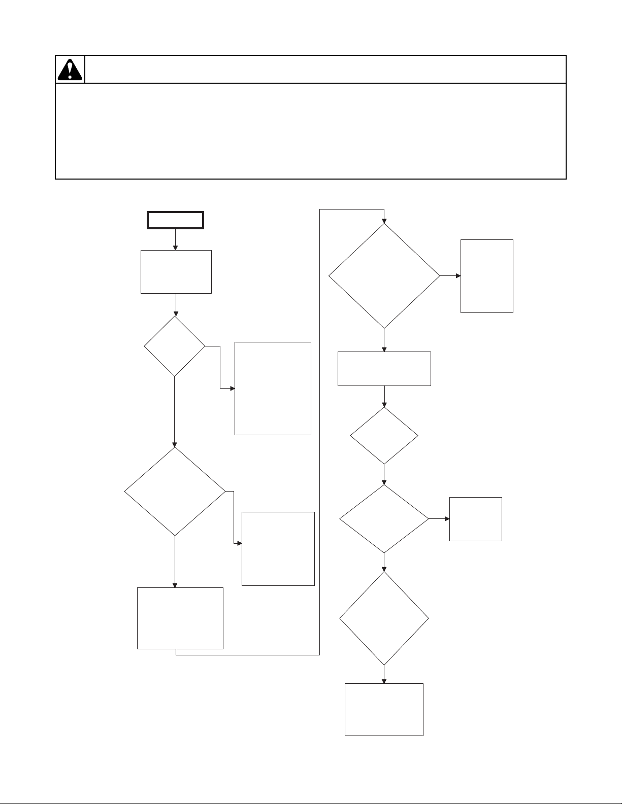
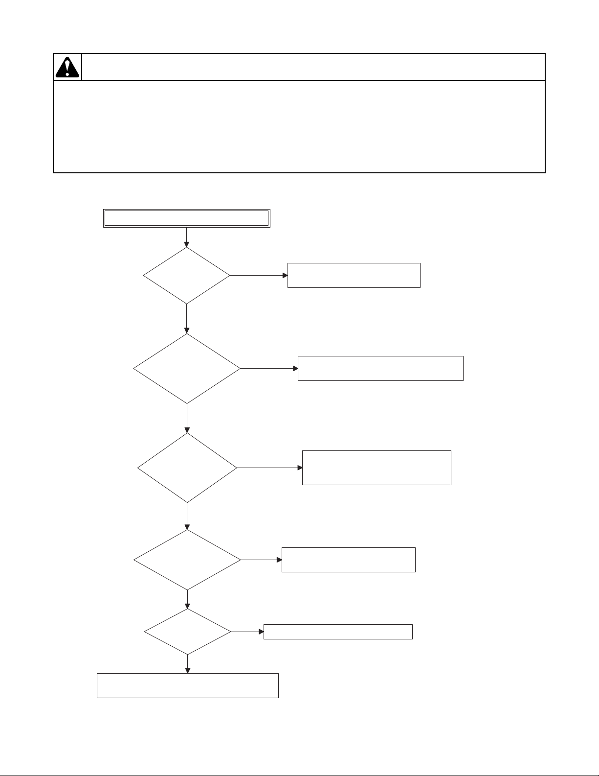
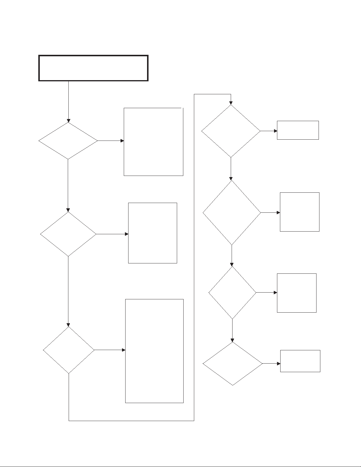
8. No Spin (continued)
FLW1816S
No spin
Allow unit to go
through complete
final spin cycle.
Does unit spin at
high speed?
Motor and
motor control
board are
operating
properly. Do
not replace
them.
Yes
Check for
obstruction
and damage
around drum.
No
With no load, rapid
advance to final spin
or run factory test
procedure to check
spin operation. Close
door and start washer.
BEFORE replacing
the motor control
board, conduct the
following tests.
No
Does
drum spin
freely by
hand?
Is load
out-of-
balance?
Unit makes multiple
attempts to rebalance out-ofbalance loads. If all
attempts fail, final
high speed spin is
aborted. ONLY
proper loading can
correct problem.
Yes
Is
there a slow
drain, clogged
pump or
oversudsing
condition?
Pressure sensor
must register an
"empty" condition
before unit will
enter spin. Clear
drain or pump. Use
less detergent.
Yes
No
No
Does unit
spin now?
No
Check for
broken shocks.
Yes
Using
Water Level
Display Mode, is
water level showing
below one inch
in spin
step?
Check pressure
hose for clog and
pressure sensor
wiring for connection
and damage.
No
FLW1816S
General Troubleshooting
806221 19
General Troubleshooting
To reduce the risk of electric shock, fire, explosion, serious injury or death:
• Disconnect electric power to the washer before servicing.
• Never start the washer with any guards/panels removed.
• Whenever ground wires are removed during servicing, these ground wires must be
reconnected to ensure that the washer is properly grounded.
• Motor not grounded! Disconnect electric power before servicing motor.
W485
WARNING
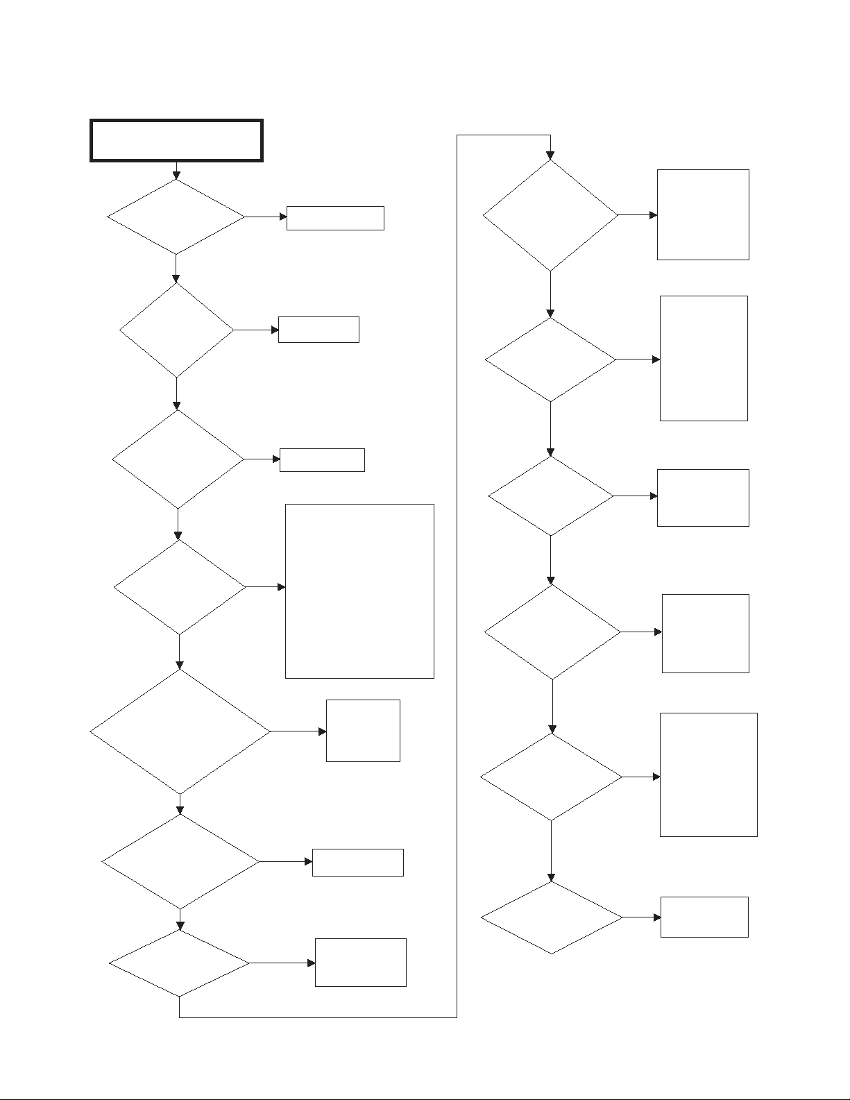
FLW1809S
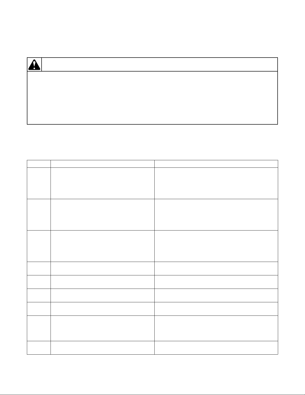
Excessive Vibration and/or Noise During Spin
Is
the load of proper
size?
Add or remove items as needed to ensure load size is correct.
No
Does
the wash load
contain the proper
mix of laundry
items?
Yes
Add or remove items as needed to ensure proper mix of
items (e.g. do not wash towels and sheets together).
No
Is
machine
level?
Yes
Level machine properly.
Refer to Installation Instructions.
No
Yes
Are
all panels on
machine?
Replace all panels.
No
Yes
Are
the front and rear
bearings making
excessive
noise?
Replace the bearings as needed.
Yes
Lift up on
the basket at the
front of the tub. Is there any
up and down play that would
indicate bearing
wear?
No
Replace the bearings as needed.
Yes
Are
motor and drive
pulleys aligned and
on tight?
Align/tighten pulleys as needed.
No
FLW1809S
9. Excessive Vibration and/or Noise During Spin
20 806221
To reduce the risk of electric shock, fire, explosion, serious injury or death:
• Disconnect electric power to the washer before servicing.
• Never start the washer with any guards/panels removed.
• Whenever ground wires are removed during servicing, these ground wires must be
reconnected to ensure that the washer is properly grounded.
• Motor not grounded! Disconnect electric power before servicing motor.
W485
WARNING
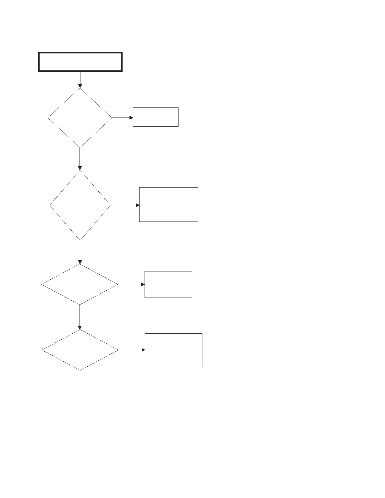
10. Excessive Cycle Time
FLW1819S
Excessive Cycle Time
Is water passing
through the drain during
fill?
Repair/replace drain valve as necessary.
Yes
Is the machine
slow to fill?
No
Check water pressure and/or check for
clogged screens in fill hoses.
Yes
Check pressure sensor and associated hoses for
obstructions or leaks. Repair/replace as necessary.
If
equipped with heat, is
it taking too long to
heat?
Troubleshoot heat output circuit.
No
Yes
Are
there load balance
issues?
Ensure machine is loaded properly.
Yes
No
No
Is there
an oversudsing
condition?
Reduce amount of detergent used.
Yes
No
FLW1819S
General Troubleshooting
806221 21
Section 4
To reduce the risk of electric shock, fire, explosion, serious injury or death:
• Disconnect all electric power to the machine and accessories before servicing.
• Close gas shut-off valve to gas dryer before servicing.
• Never start machine with any guards/panels removed.
• Whenever ground wires are removed during servicing, these ground wires must be
re
connected to ensure that the machine is properly grounded.
• Washer motor not grounded! Disconnect electric power before servicing motor.
W502
WARNING
Dryer Control Troubleshooting
IMPORTANT: Refer to wiring diagram for aid in
testing dryer components.
7. Dryer Error Code Listing
Display Description Cause/Corrective Action
Locked rotor error: The motor is not sensed as
rotating when it should be.
Open thermistor error: The thermistor circuit
is sensed as being physically open.
Shorted thermistor error: The thermistor
circuit is sensed as being shorted.
Motor output shorted error: Hardware error. Terminate cycle. Replace output board. Power down
Door input acquisition error: Hardware error. Terminate cycle. Replace output board. Power down
Centrifugal switch input acquisition error:
Hardware error.
High limit thermostat input acquisition error:
Hardware error.
Output board communication error:
Communication failure.
Output board not ready error: Hardware
failure.
(continued)
22 806221
Terminate cycle and check that nothing is obstructing
motor rotation. Check wire harness connection
between motor, user control and output board, or try
replacing the user control or the output board. Clear
error with a key press.
Remove any lint build up around thermistor. Check
wire harness connection between thermistor and
harness. If problem persists replace thermistor, harness
or output board. Thermistor must no longer be seen as
open to clear.
Remove any lint build up around thermistor. Check
wire harness connection between thermistor and
harness. If problem persists replace thermistor, harness
or output board. Thermistor must no longer be seen as
shorted to clear.
machine to clear.
machine to clear.
Terminate cycle. Replace output board. Power down
machine to clear.
Advance cycle to cool down. Replace output board.
Power down machine to clear.
Power down machine to clear, power up and try again.
If error persists, check harness connection between
user control and output board, or try replacing the user
control or the output board.
Terminate cycle. Replace output board. Power down
machine to clear.

Dryer Control Troubleshooting
(continued)
Display Description Cause/Corrective Action
Brownout/voltage configuration error:
Unexpected supply voltage.
Check the harness connections between the user
control and the output board. If the user control was
replaced, set dipswitch #1 to the same setting as the
previous control. If reworking the machine to use a
different supply voltage, the dip switch #1 setting may
need to be changed. If the dip switch #1 setting is
changed, power down machine, power up and try
again.
Board ID error: Incorrect replacement
control.
Terminate cycle. Replace user control or output board
with correct part. Power down machine to clear.
806221 23
Dryer Control Troubleshooting
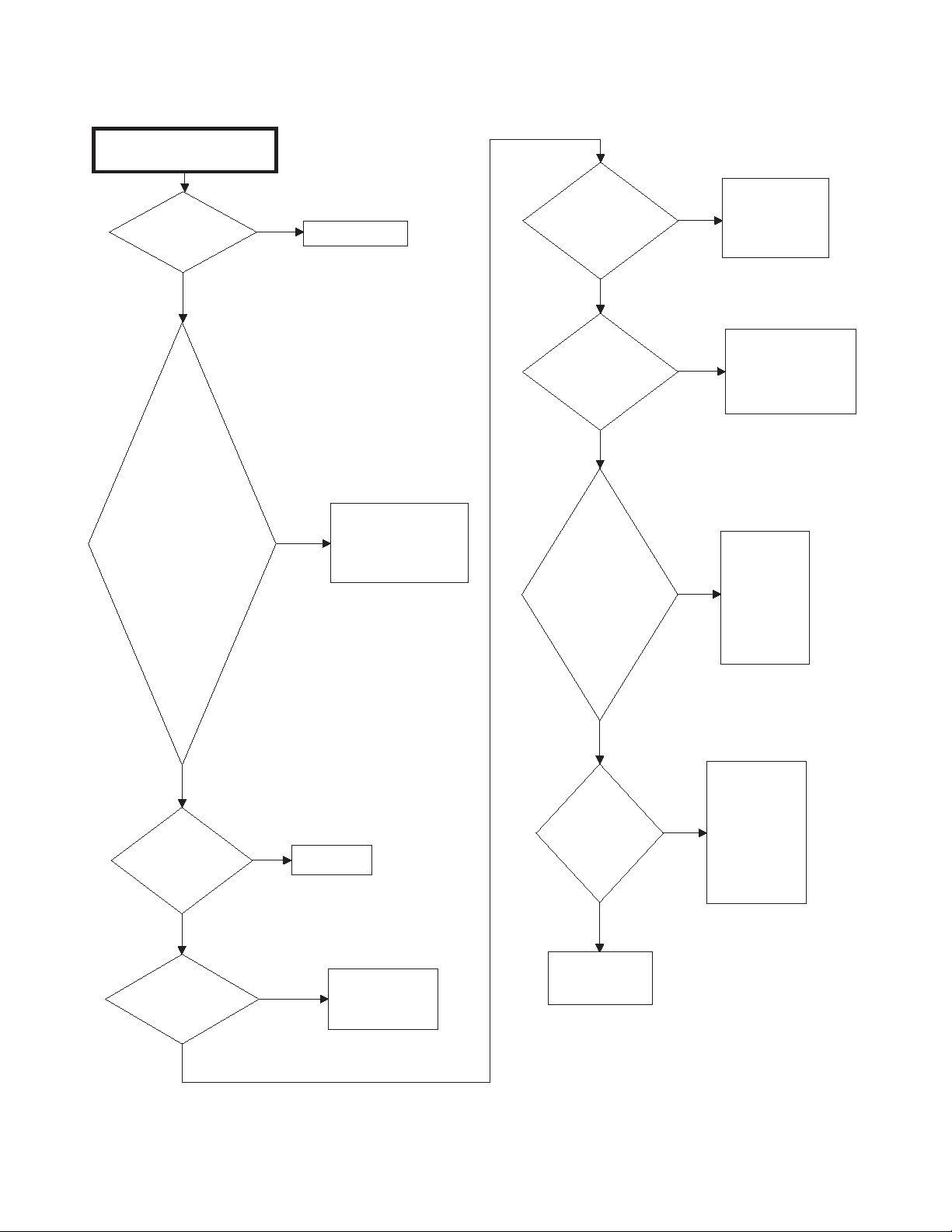
8. Dryer Motor Does Not Run
Dryer motor does not run.
Is power cord
plugged in?
Yes
Is electrical
power off or fuse
blown? Check
laundry room for
blown or loose
fuse(s), or open
circuit
breaker(s). The
dryer itself
doesn't have an
electrical fuse.
No
Plug in cord.
Yes
Turn power on or
replace fuse. Check
both fuses for
electric models.
Is
timer/electronic
control improperly
set?
No
Is
timer/electronic
control
inoperative?
No
Are motor
starting
functions
inoperative,
does not
start, or motor
just hum?
Yes
Yes
Yes
Reset
timer/electronic
control or try
another cycle.
Te st
timer/electronic
control and replace
if inoperative.
Refer to
Adjustments
section to
check motor
switch and
motor
windings.
No
No
Is loading
door closed?
Yes
Is door switch
inoperative?
No
No
Yes
Close door.
Test switch and
replace if
inoperative.
Is motor
dead,
won't run?
No
Continued on
next page.
Refer to
Adjustments
section to
Yes
check motor
switch, motor
windings and
main windings.
SWD1706S-a
24 806221
8. Dryer Motor Does Not Run (continued)
SWD1706S-b
Continued from
previous page.
Is power cord
miswired?
Refer to wiring
diagram for
correct wiring.
Refer to wiring
diagram.
Is wiring
broken, loose
or incorrect?
Is motor wire
harness
connection
block loose?
Firmly press
connection
block onto
motor switch.
Remove belt
and
determine if
motor shaft
will spin.
Replace motor
if shaft is
locked up.
Is there a bind
in motor
bearing?
Is motor
centrifugal
switch sticky
or plugged
with lint?
Remove
dust or lint
and spray
with a
cleaner and
lubricant.
Wait two or three
minutes for
overload protector
to reset. If
protector cycles
repeatedly, refer
to next flowchart.
Has motor
overload
protector
cycled?
Yes
No
Yes
No
Yes
No
Yes
No
Yes
No
Yes
Dryer Control Troubleshooting
806221 25
Dryer Control Troubleshooting
Dryer stops in cycle, quits after first few
loads, has burning smell or cycles on
motor thermal protector.
Is voltage
incorrect?
Refer to nameplate in
door well for correct
voltage. Refer to
Installation
Instructions (supplied
with unit) for
electrical
requirements.
Yes
Is clothes
load too
large?
No
Remove part of
load. A normal
washer load is a
normal dryer load.
Maximum load:
dryer cylinder one
half full of wet
clothes.
Yes
Is clothes
cylinder
binding?
Check cylinder for
binding and "out of
round" condition.
Check front and rear
bulkheads for
warping. Check
support rollers for
binding. Check
cylinder seals and
glides for wear or
damage. Check for
clothes lodged
between cylinder
baffle and bulkhead.
No
Yes
Is there
broken, loose
or incorrect
wiring?
Refer to wiring
diagram.
Yes
Are motor
switch
functions
inoperative?
Refer to
Adjustments
section to
check switch
and windings.
Yes
Is there a
short in
motor
winding?
No
Is a clothes
item caught in
fan?
Check fan for
obstruction.
Yes
No
SWD1690S
Refer to
Adjustments
section to
check switch
and windings.
No
Yes
No
9. Dryer Stops in Cycle; Quits After the First Few Loads; Has a Burning Smell; Cycles On Motor Thermal Protector
26 806221
10. Dryer Motor Runs But Cylinder Does Not Turn
Dryer motor runs but
cylinder does not turn.
Is motor drive
pulley loose?
Tighten pulley.
Is belt
installed on
pulley?
No
Install belt.
No
Is cylinder
belt broken?
Replace belt.
Yes
Is clothes
cylinder
binding?
No
Check cylinder for
binding and "out of
round" condition. Check
front and rear
bulkheads for warping.
Check cylinder rollers
for binding. Check
cylinder seals and
glides for wear or
damage.
Is idler lever
spring broken,
weak or
disconnected?
Replace or
reconnect
spring.
Yes
Is there oil on
cylinder?
Wipe oil from
cylinder.
Yes
Is belt "inside
out" ?
Reinstall belt
with ribbed
surface
against
cylinder.
Yes
Is idler arm
binding?
Add grease
between idler
arm and
motor mount.
Replace idler
arm and bolt
if needed.
Yes
No
Is dryer
overloaded?
Remove some
laundry from
dryer.
Yes
No
SWD1691S
Yes
Yes
Yes
No
Is the wrong
motor
installed?
Refer to parts
manual for
correct motor
part number.
Is the wrong
belt installed?
Check belt
part number
against correct
part number in
parts manual
and replace
belt if needed.
Is idler arm
bent?
Replace idler
arm.
No
No
No
Yes
Yes
Yes
Is belt routed
on wrong side
of idler lever?
Reroute belt.
No
No
No
Yes
Dryer Control Troubleshooting
806221 27
Dryer Control Troubleshooting
11. Dryer Motor Does Not Stop
Dryer motor does not stop.
Is wiring to
motor switch
incorrect?
No
Is motor
centrifugal
switch sticky
or plugged
with lint?
No
Is door switch
inoperative?
Yes
Yes
Refer to wiring
diagram.
Remove dust or lint
and spray with a
cleaner and
lubricant.
Yes
Test switch and
replace if
inoperative.
No
Is
timer/electronic
Yes
control
inoperative?
28 806221
Te st
timer/electronic
control and replace
if inoperative.
SWD1707S
12. Dryer Runs Only When Door is Open
Dryer runs only when door is
open.
Is door switch
miswired?
Rewire door
switch. Refer to
wiring diagram.
Yes
SWD1693S
Replace door switch.
No
Dryer Control Troubleshooting
806221 29
 Loading...