

Alliance Laundry Systems HX018PVQM7, HX18PVQM7, HX018PVXM7, HX18PVQM6, HX18PVQU6 Programming Manual
...Page 1
Washer-Extractors
Cabinet Freestanding
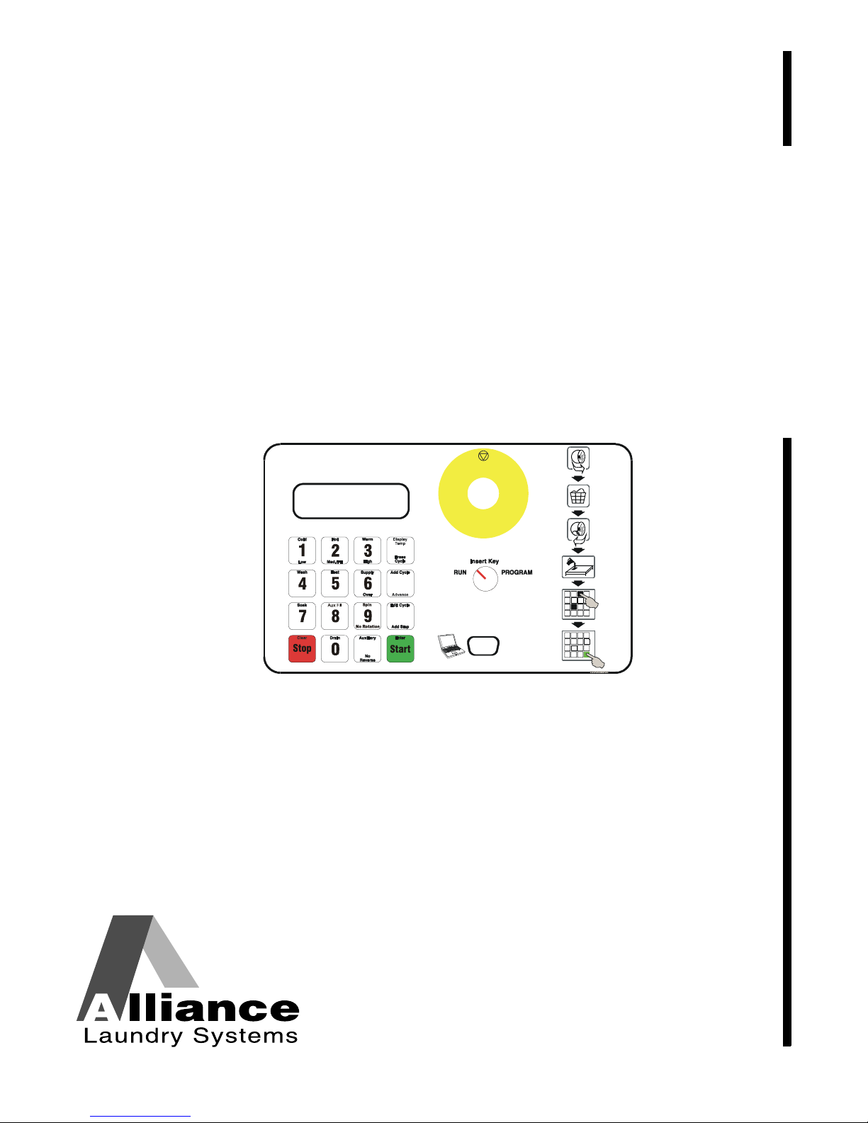
WE-8 Computer
Programming
Keep These Instructions for Future Reference.
(If this machine changes ownership, this manual must accompany machine.)
www.comlaundry.com
Part No. 9001889R7
July 2011
Page 2

Page 3

NOTE: The WARNING and IMPORTANT instructions appearing in this manual are not meant to cover all
possible conditions and situations that may occur. It must be understood that common sense, caution, and
carefulness are factors which cannot be built into these washers. These factors MUST BE supplied by the
person(s) installing, maintaining, or operating the washer.
Always contact the distributor, service agent, or the manufacturer about any problems or conditions you do not
understand.
Failure to install, maintain, and/or operate this machine according to the manufacturer's
instructions may result in conditions which can produce bodily injury and/or property
damage.
W030
WARNING
© Copyright, Alliance Laundry Systems LLC – DO NOT COPY or TRANSMIT9001889
1
Page 4

Table of
Introduction......................................................................................... 3
Model Identification ............................................................................. 3
Contents
Programming ...................................................................................... 4
Setup of the Machine............................................................................ 4
Version of Control ................................................................................ 7
Language on Display (Version 1.15 and later ONLY) .................... 7
Setup of the Chemical Hold Feature
(Version 1.11 and later ONLY)...................................................... 7
Program Storing Mode ......................................................................... 7
Explanation of the Step Functions........................................................ 8
Example Making a New Program......................................................... 14
Edit a Cycle........................................................................................... 18
Change a Complete Step.................................................................. 18
Changing the Time of a Step ........................................................... 20
Delete a Step .................................................................................... 22
Insert a Step...................................................................................... 23
Delete a Cycle....................................................................................... 25
Reloading Previous Settings................................................................. 26
Cycle Count .......................................................................................... 27
Reading Cycle Count ....................................................................... 27
Calibration of the Machine ................................................................... 28
Speed Calibration.................................................................................. 29
Pre-Programmed Cycles .................................................................... 30
Inverter Drive Error Codes............................................................... 56
© Copyright 2011, Alliance Laundry Systems LLC
All rights reserved. No part of the contents of this book may be reproduced or transmitted in any form or by any
means without the expressed written consent of the publisher.
2
© Copyright, Alliance Laundry Systems LLC – DO NOT COPY or TRANSMIT
9001889
Page 5

Introduction
Model Identification
Information in this manual is applicable to these
models:
18
25
33
35
40
55
75
100
135
165
200
HX018PVQM7
HX018PVXM7
HX18PVQM6
HX18PVQM7
HX18PVQU6
HX18PVXM6
HX18PVXM7
HX025PVQM7
HX025PVXM7
HX25PVQM6
HX25PVQM7
HX25PVQU6
HX25PVXM6
HX25PVXM7
UX33PVNA7 UX33PVPA7 UX33PVQA7 UX33PVQM7 UX33PVXA7 UX33PVXM7
HX035PVQM7
HX035PVXM7
HX35PVQM6
HX35PVQM7
HX35PVQU6
HX35PVXM6
HX35PVXM7
UX40PVNA7 UX40PVPA7 UX40PVQA7 UX40PVQM7 UX40PVXA7 UX40PVXM7
HX055PVNU7
HX055PVQU7
HX055PVXU7
HX55PVNU6
HX55PVNU7
HX55PVQU6
HX075PVNU7
HX075PVPU7
HX075PVQU7
HX75PVNU6
HX75PVNU7
HX100PVNU6
HX100PVNU7
HX100PVPU7
HX135PVNU6
HX135PVNU7
HX135PVPU7
HX165PVNU6
HX165PVNU7
HX165PVPU7
HX200PVNU7
HX200PVPU7
HX18PVXU6
SX018PVPA7
SX018PVQM7
SX018PVXM7
SX18PVPA7
SX18PVQM6
SX18PVQM7
HX25PVXU6
SX025PVQM7
SX025PVXM7
SX25PVQM6
SX25PVQM7
SX25PVQU6
SX25PVXM6
HX35PVXU6
SX035PVNM7
SX035PVQM7
SX035PVXM7
SX35PVNM7
SX35PVQM6
SX35PVQM7
HX55PVQU7
HX55PVXU6
HX55PVXU7
SX055PVNU7
SX055PVPU7
SX055PVQU7
HX75PVPU7
HX75PVQU6
HX75PVQU7
SX075PVNU7
SX075PVPU7
HX100PVQU6
HX100PVQU7
SX100PVNU6
HX135PVQU6
HX135PVQU7
SX135PVNU6
HX165PVQU6
HX165PVQU7
SX165PVNU6
HX200PVQU7
SX200PVNU7
SX18PVQU6
SX18PVXM6
SX18PVXM7
SX18PVXU6
UX018PVNA7
UX018PVPA7
UX018PVQA7
SX25PVXM7
SX25PVXU6
UX025PVNA7
UX025PVPA7
UX025PVQA7
UX025PVQM7
UX025PVXA7
SX35PVQU6
SX35PVXM6
SX35PVXM7
SX35PVXU6
UX035PVNA7
UX035PVPA7
UX035PVQA7
SX055PVXU7
SX55PVNU6
SX55PVNU7
SX55PVPU6
SX55PVPU7
SX55PVQU6
SX075PVQU7
SX75PVNU6
SX75PVNU7
SX75PVPU7
SX75PVQU6
SX100PVNU7
SX100PVPU7
SX100PVQU6
SX135PVNU7
SX135PVPU7
SX135PVQU6
SX165PVNU7
SX165PVPU7
SX165PVQU6
SX200PVPU7
SX200PVQU7
UX018PVQM7
UX018PVXA7
UX018PVXM7
UX18PVNA6
UX18PVNA7
UX18PVNU6
UX18PVPA6
UX025PVXM7
UX25PVNA6
UX25PVNA7
UX25PVNU6
UX25PVPA6
UX25PVPA7
UX25PVPU6
UX035PVQM7
UX035PVXA7
UX035PVXM7
UX35PVNA6
UX35PVNA7
UX35PVNU6
UX35PVPA6
SX55PVQU7
SX55PVXU6
SX55PVXU7
UX055PVNU7
UX055PVPU7
UX055PVQU7
SX75PVQU7
UX075PVNU7
UX075PVPUU
X075PVQU7
UX75PVNU6
SX100PVQU7
UX100PVNU6
UX100PVNU7
SX135PVQU7
UX135PVNU6
UX135PVNU7
SX165PVQU7
UX165PVNU6
UX165PVNU7
UX200PVNU7
UX200PVPU7
UX18PVPA7
UX18PVPU6
UX18PVQA6
UX18PVQA7
UX18PVQM6
UX18PVQM7
UX18PVQU6
UX25PVQA6
UX25PVQA7
UX25PVQM6
UX25PVQM7
UX25PVQU6
UX25PVXA6
UX25PVXA7
UX35PVPA7
UX35PVPU6
UX35PVQA6
UX35PVQA7
UX35PVQM6
UX35PVQM7
UX35PVQU6
UX055PVXU7
UX55PVNU6
UX55PVNU7
UX55PVPU6
UX55PVPU7
UX55PVQU6
UX75PVNU7
UX75PVPU6
UX75PVPU7
UX75PVQU6
UX75PVQU7
UX100PVPU6
UX100PVPU7
UX100PVQU6
UX135PVPU6
UX135PVPU7
UX135PVQU6
UX165PVPU6
UX165PVPU7
UX165PVQU6
UX200PVQU7
UX18PVXA6
UX18PVXA7
UX18PVXM6
UX18PVXM7
UX18PVXU6
UX25PVXM6
UX25PVXM7
UX25PVXU6
UX35PVXA6
UX35PVXA7
UX35PVXM6
UX35PVXM7
UX35PVXU6
UX55PVQU7
UX55PVXU6
UX55PVXU7
UX100PVQU7
UX135PVQU7
UX165PVQU7
9001889
© Copyright, Alliance Laundry Systems LLC – DO NOT COPY or TRANSMIT
3
Page 6
Setup of the Machine
Program Cycle 00
Units: English
System Program
_X18PV
System Program
_X25PV
Units: Metric
Drain 1 : Valve
Drain 2 : None
Drain 1 : Pump
Drain 2 : None
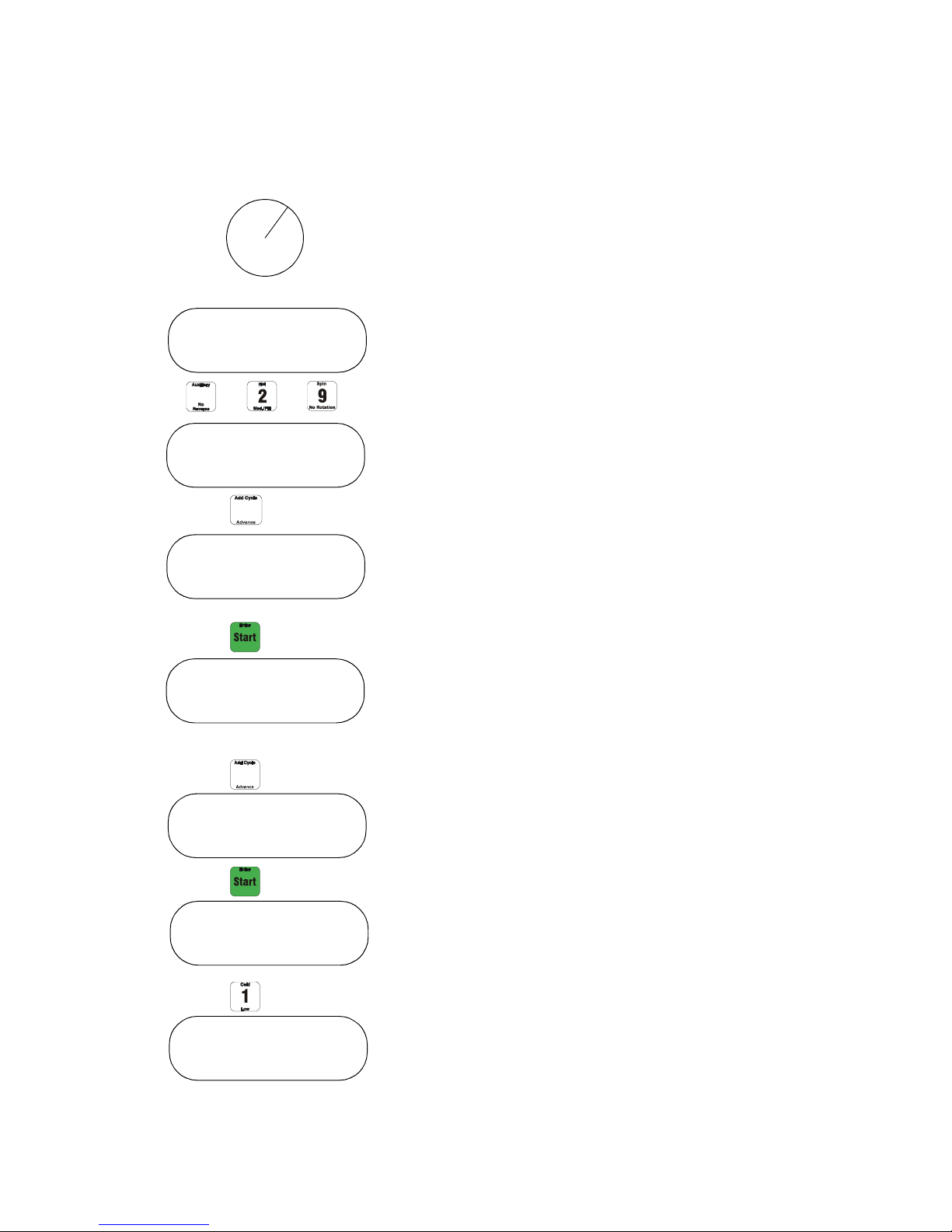
RUN PROGRAM
Programming
Turn key from Run to Program
To go to the main setup of the machine, press
“Auxiliary”, “2”, “9”.
To change the machine type, press the “Advance”
button.
The following types are possible:
_X18PV _X40PV _X135PV
_X25PV _X55PV _X165PV
_X33PV _X75PV _X200PV
Press the “Advance” button until the right type of
machine is selected. Press the “Enter” button.
Select the desired units.
NOTE: English means level in inch and
temperature in °F.
Metric means level in cm and temperature in °C.
Press the “Advance” button to change the units.
4
© Copyright, Alliance Laundry Systems LLC – DO NOT COPY or TRANSMIT 9001889
Press the “Enter” button.
Select the type of drain valve.
Press “1” to change drain 1 to pump or valve.
Press “2” to change drain 2 to pump, valve or none.
Page 7

Programming
Options :
Advance : Yes
Advance : No
Options :
Aux Fill
Heating : 6 kW
Heating : 9 kW
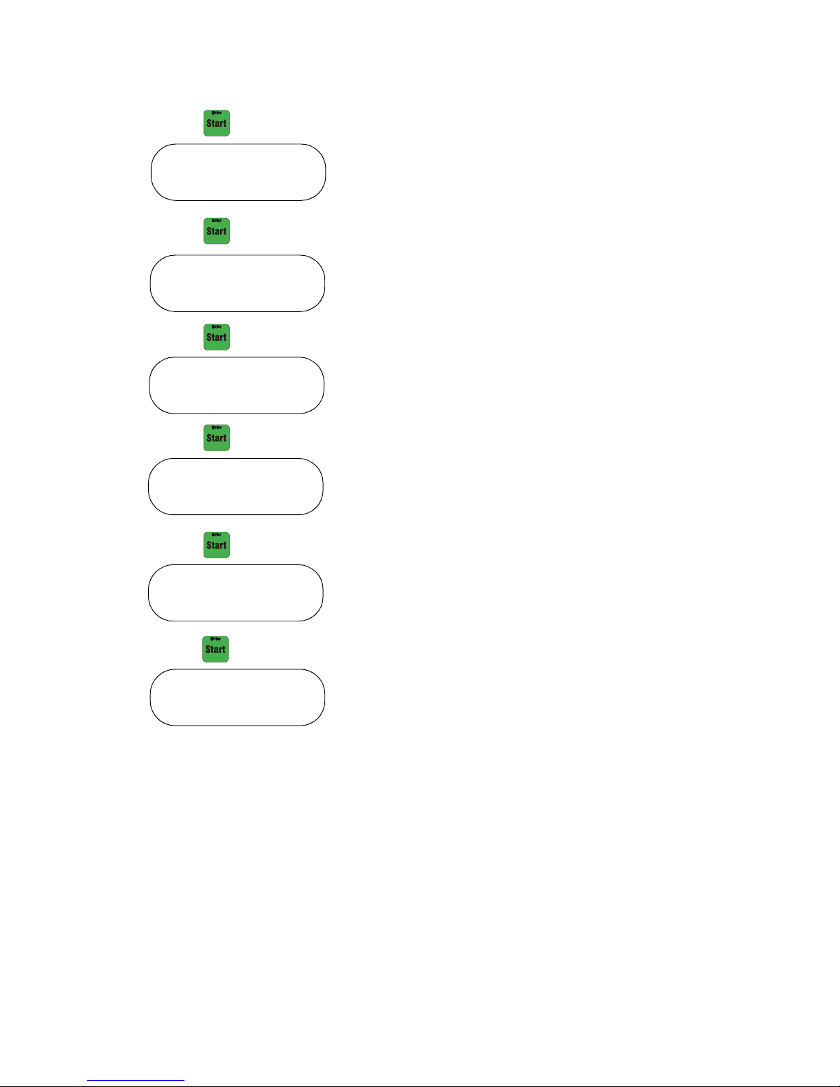
Press the “Enter” button to select options.
Press the “Aux Fill” button for auxiliary fill option or
press “Enter” for heating.
If heating is selected, the user can fill in the kW of the
electrical heating (example: 9 kW).
Press “0”, “9”.
Press “Enter” to select advance mode in run mode yes
or no.
Press “Advance” to change between yes and no.
9001889
© Copyright, Alliance Laundry Systems LLC – DO NOT COPY or TRANSMIT
5
Page 8
Programming
Level : hyst 2"
Enter to save ?
Program Cycle 00
Temp : hyst 3°F
Spin retries : 5
Address : 0
Press “Enter” to set the hysteresis level (level at which
water drops before it senses it must refill).
If English is selected for units, this value will be in
inches. If Metric is selected for units, this value will be
in cm.
Select between 1 to 9 cm or inches.
Press “Enter” to select the temperature hysteresis
(level at which temperature drops before machine
senses it must reheat).
If English is selected for units, this value will be in °F.
If Metric is selected for units, this value will be in °C.
Select 1 to 9 °C or °F.
Press the “Enter” button to set the spin retries.
Select 1 to 9 spin retries.
Press “Enter” to set the network address of the
machine. If this is not used, press “Enter”.
The address of the machine has to be set if you
network the machine. Each machine should have a
different address.
Fill in between 00 and 99.
Press “Enter” to finish the settings.
Press “Enter” to save the settings or press “Stop” to
exit without saving.
6
© Copyright, Alliance Laundry Systems LLC – DO NOT COPY or TRANSMIT
9001889
Page 9

Programming
Version of Control
To determine control version, apply power to machine.
Control will display version of control (i.e., 1.15).
Language on Display (Version 1.15 and
later ONLY)
To set a different language on the WE-8 display:
1. Turn key from RUN to PROGRAM.
2. Press “Auxiliary”, “2” and “9” to enter set-up
mode.
3. English will display. Press “Advance” until
desired language displays (French, Italian,
Spanish and German).
4. Press “Enter” keypad.
5. Press “Enter” to advance through set-up mode.
6. Wait until information is saved.
7. Turn key from PROGRAM to RUN.
8. Display will read language chosen for all cycles.
Setup of the Chemical Hold Feature
(Version 1.11 and later ONLY)
At power up, verify that model is at least
version 1.11. Refer to version of Control Section.
Earlier versions do not have this chemical hold
feature.
Insert key into key switch and turn to Program.
NOTE: If chemical hold is off, then supplies 4
through 9 are controlled exactly like supplies 1
through 3. A switch closure/opening between pins 1
and 4 of the COIN header on the output board will
have no effect.
Program Storing Mode
The WE-8 control is capable of 99 total cycles. One
cycle contains 1 or more steps.
One step is a function of the wash program
(example: heat).
Choose between the following functions:
Fill: To fill the machine with water.
Wash: Wash action of the machine.
Supply: To add detergent to the wash (liquid or
powder).
Cooldown: Cool to programmed temperature
Heat: To heat the water.
Soak: The wash will be soaked for a
programmed time and a programmed
temperature.
Aux: A relay contact will close for a
programmed time.
Spin: To spin the machine for a programmed
time and RPM.
Drain: To drain the water from the machine.
Push the Auxiliary key, the 2 key, and the 9 key
in succession to enter System Program Mode.
Push the Start key 10 times to arrive at the
Chemical hold choice.
Push the Add Cycle/Advance key to toggle the
Chemical hold feature either Yes (on) or No (off).
Push the Start key twice to save changes and exit
System Program Mode.
Turn key switch to Run.
NOTE: If chemical hold is on, then a switch
closure/opening between pins 1 and 4 of the COIN
header on the output board will control supplies 4
through 9. A closure will turn the programmed
supply/ies on and count down the time for the
supply to be on. An opening will turn the
programmed supply/ies off and halt the time for
the supply to be on.
9001889
© Copyright, Alliance Laundry Systems LLC – DO NOT COPY or TRANSMIT
7
Page 10
Programming
Step XX Cycle XX
Warm
Step XX Cycle XX
Warm Low
Step XX Cycle XX
0 min
Step XX Cycle XX
5 min 30 sec
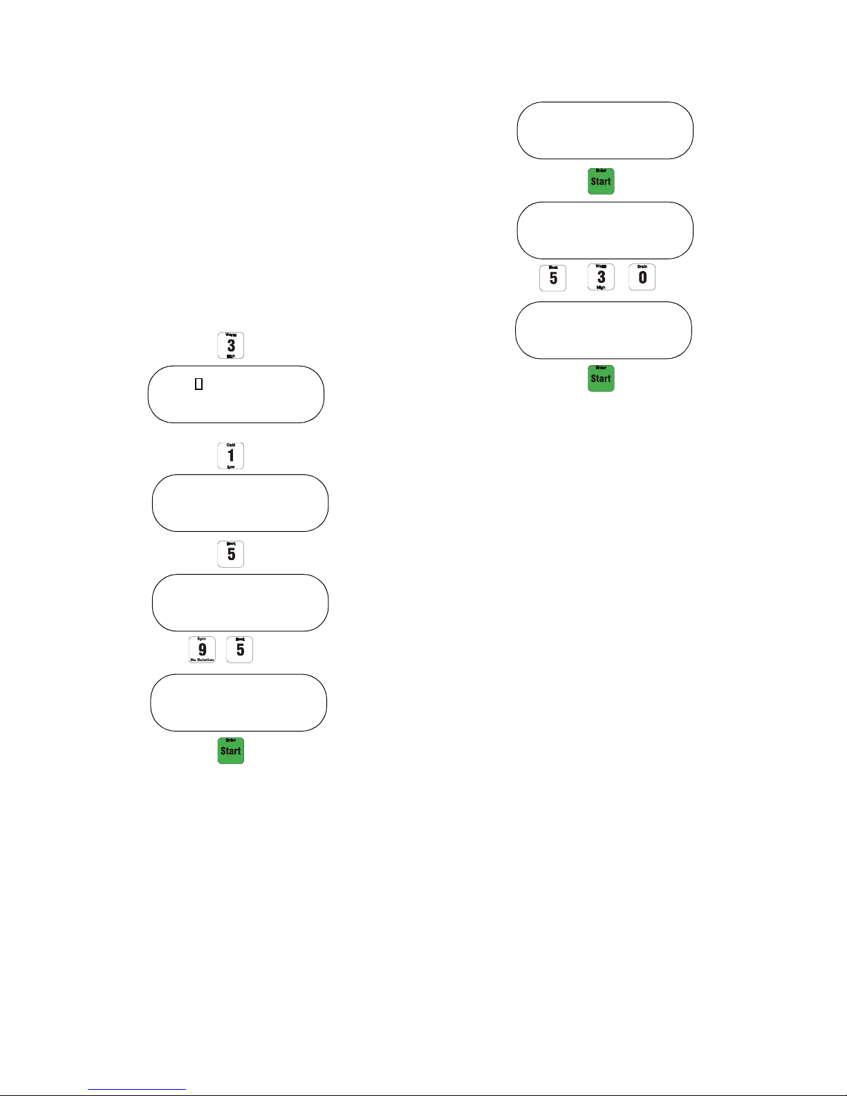
Explanation of the Step Functions
Fill:
Choose between 4 water inlet configurations and
3 water levels.
Water Inlet Configurations:
Cold: Only opens the cold water valve.
Hot: Only opens the hot water valve.
Warm: Opens the cold and hot water valves.
Aux Fill: Opens an auxiliary water valve
if installed.
Water Levels:
Low: Low water level.
Med: Medium water level.
High: High water level.
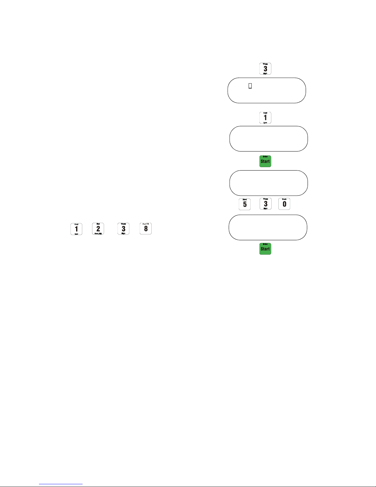
The inlet configurations and the fill levels appear on
the keypad, keys 1, 2, 3 and 8.
Example: Warm Low (time limit 5 minutes
30 seconds)
Be sure to select first the inlet configuration and then
the water level.
Then you will be asked for the step time limit.
NOTE: If a fill error occurs, then machine has
2 minutes to finish filling. If after 2 minutes it has
not finished filling, cycle is aborted.
8
© Copyright, Alliance Laundry Systems LLC – DO NOT COPY or TRANSMIT
9001889
Page 11
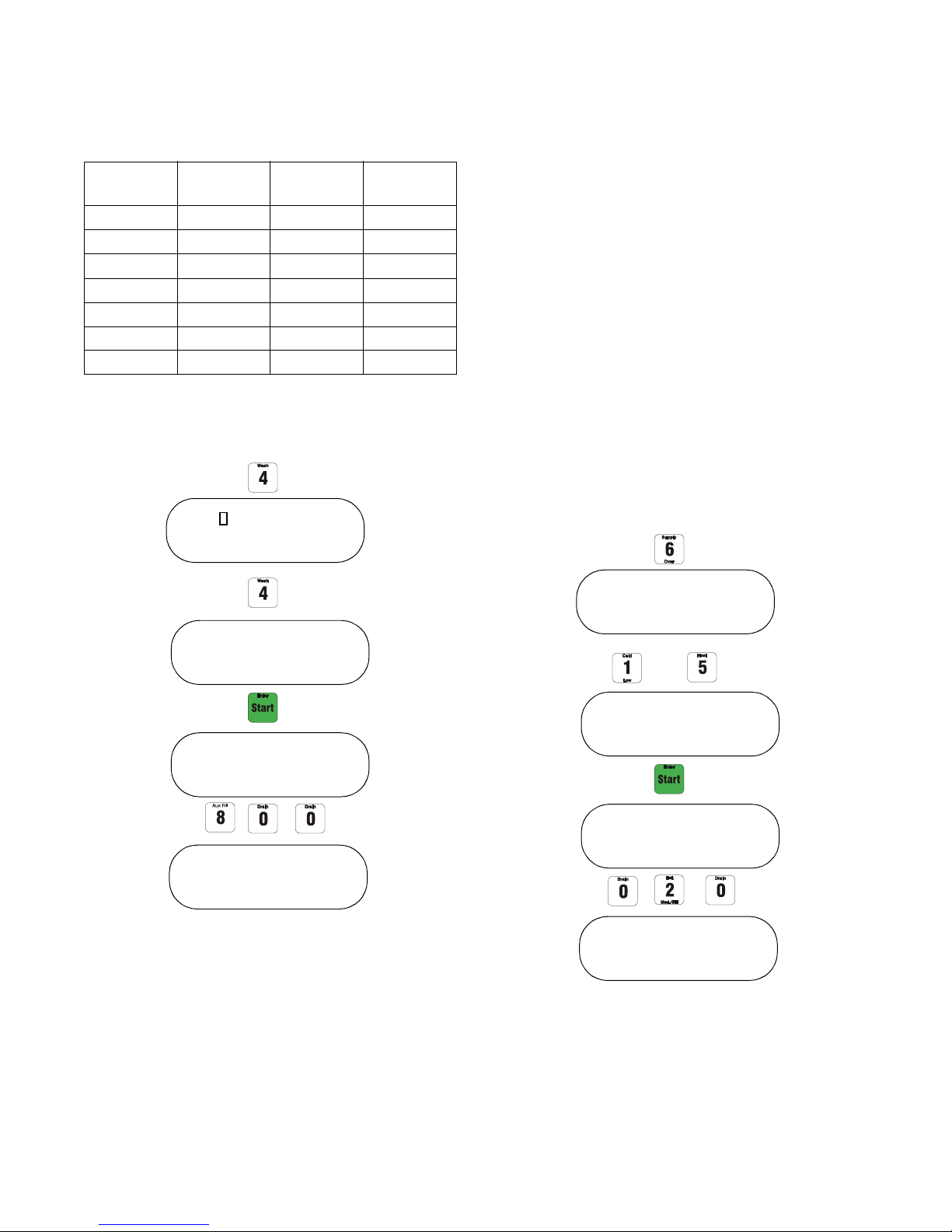
It is possible to more accurately control the
Step XX Cycle XX
Warm
Step XX Cycle XX
Warm Low
Step XX Cycle XX
0°F
Step XX Cycle XX
95°F
Step XX Cycle XX
95°F Low
Step XX Cycle XX
0 min
Step XX Cycle XX
5 min 30 sec
temperature of water coming in to the machine during
a fill step. This does not apply to “Aux Fill” step. The
control will mix the hot and cold water inlet to the
temperature programmed in the fill function. To fill in
the temperature, select the water inlet type and the
water level. Press the “Heat” button and the control
will ask the temperature. In this way the water inlet
type selected is of no use because the control will mix
between the cold and hot water inlet to reach the
temperature.
Example: Fill to low level and 95°F (step time limit:
5 minutes 30 seconds).
Programming
9001889
© Copyright, Alliance Laundry Systems LLC – DO NOT COPY or TRANSMIT
9
Page 12
Programming
Step XX Cycle XX
Wash
Step XX Cycle XX
Wash 4 10/20
Step XX Cycle XX
0 min
Step XX Cycle XX
8 min 00 sec
Step XX Cycle XX
Supply
Step XX Cycle XX
Supply 1 5
Step XX Cycle XX
0 min
Step XX Cycle XX
0 min 20 sec
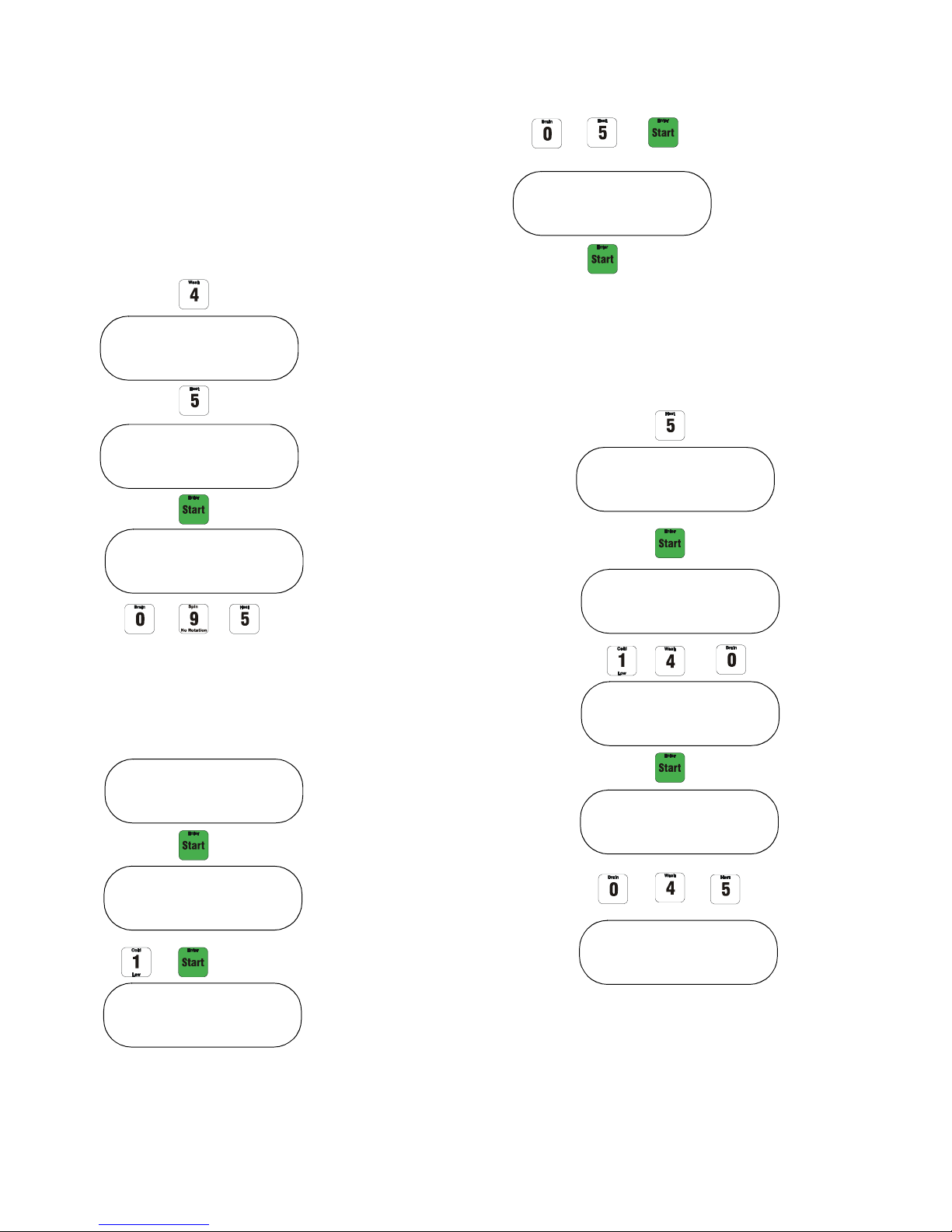
Heat:
Was h :
Choose between 7 different preset wash actions.
Action
Time (sec)
Stop Time
(sec)
G-force
Wash 1 18 3 0.5
Wash 2 3 27 0.5
Wash 3 0 0 0
Wash 4 10 20 0.5
Wash 5* 18 3 0.5
Wash 6 4 56 0.5
Wash 7 0 0 0
The “Wash” button is button 4 on the display.
Example: Wash 4 for 8 minutes 00 seconds.
Supply:
Choose between 9 different supplies.
Supply 1: Turns on the water valve in compartment
A of the supply box.
Supply 2: Turns on the water valve in compartment
B of the supply box.
Supply 3: Turns on the water valve in compartment
C of the supply box.
Supply 4: Activates supply pump 1.
Supply 5: Activates supply pump 2.
Supply 6: Activates supply pump 3.
Supply 7: Activates supply pump 4.
Supply 8: Activates supply pump 5.
Supply 9: Activates supply pump 6.
The Supply button is button 6.
Example: Supply 1 and 5 for 20 seconds.
* Refer to section on Wash 5 Thermal Cool-Down.
10
© Copyright, Alliance Laundry Systems LLC – DO NOT COPY or TRANSMIT
9001889
Page 13
Chemical Hold Feature
Step XX Cycle XX
Wash
Step XX Cycle XX
0°F (or 0°C)
Step XX Cycle XX
Wash 5
Enter desired temperature for load to
cool down to. Three digits must be used
for temperature. If Fahrenheit, the valid
temperature range is 80° – 200°F. If
Celcius, valid temperature range is
25° – 90°C (example: 95°F).
Step XX Cycle XX
95°F
Step XX Cycle XX
0 hours
Step XX Cycle XX
1 hours 00 min
Thermal Cool-Down
is Wash 5.
Step XX Cycle XX
1 hours 05 min
Enter time in minutes
and press “Enter”
(example: 5 min).
Step XX Cycle XX
Heat
Step XX Cycle XX
0°F
Step XX Cycle XX
140°F
Step XX Cycle XX
0 hours 45 min
Step XX Cycle XX
0 hours
Chemical supply injection can be paused. Refer to
Setup of Chemical Hold Feature.
Wash 5 Thermal Cool-Down
Immediately after a heat step, a temperature-controlled
thermal cool-down may be programmed to prevent
fiber shock from sudden cool-down.
Programming
The “Heat” button is number 5.
Example: Heat up to 140°F with the time limit of
45 minutes.
9001889
© Copyright, Alliance Laundry Systems LLC – DO NOT COPY or TRANSMIT
11
Page 14
Programming
Step XX Cycle XX
Soak
Step XX Cycle XX
0 hours
Step XX Cycle XX
2 hours 00 min
Step XX Cycle XX
2 hours 23 min
Use the key pad to fill in
the hours of the soak time
(example: 2 hours).
Now you can fill in the
minutes (example:
23 minutes).
Press “Enter”.
Step XX Cycle XX
Soak
Step XX Cycle XX
0°F
Step XX Cycle XX
32°F
Step XX Cycle XX
2 hours 00 min
Step XX Cycle XX
Soak 32°F
Use the key pad to fill in
the soak temperature
(example: 32°F).
Fill in the minutes
(example: 23 minutes).
Press “Enter”.
Step XX Cycle XX
2 hours 23 min
Step XX Cycle XX
0 hours
Use the key pad to fill in
the hours of the soak time
(example: 2 hours).
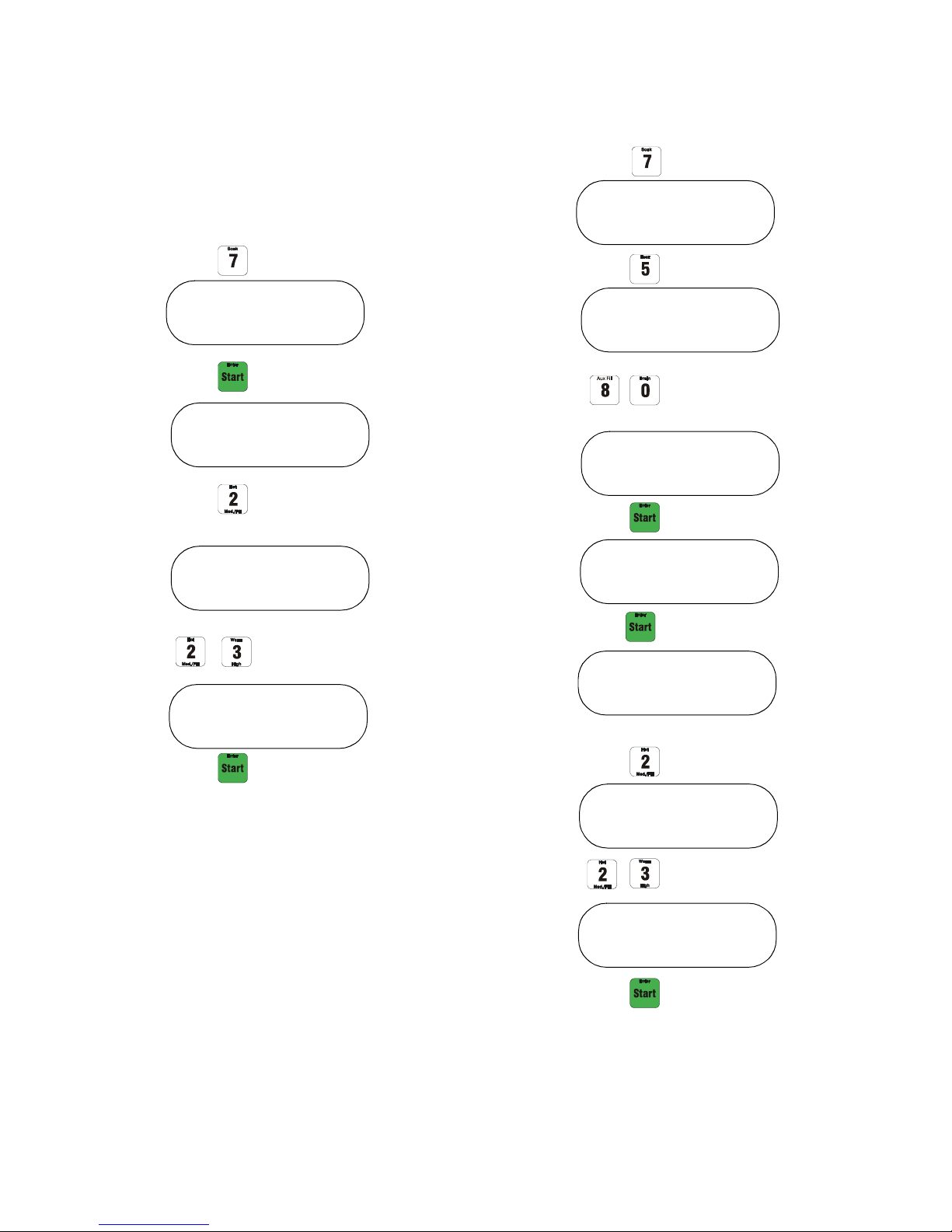
Soak:
Button 7 is the “Soak” button.
By pressing button 7, “Soak” will appear on the
display. Press “Enter” to fill in the soak time.
Example: Soak for 2 hours.
Example: Soak time of 2 hours with 32°F.
The temperature of the soak will be the temperature
programmed in the previous step. You can also change
the temperature by pressing first “Soak” and then
“Heat”.
12
© Copyright, Alliance Laundry Systems LLC – DO NOT COPY or TRANSMIT
9001889
Page 15
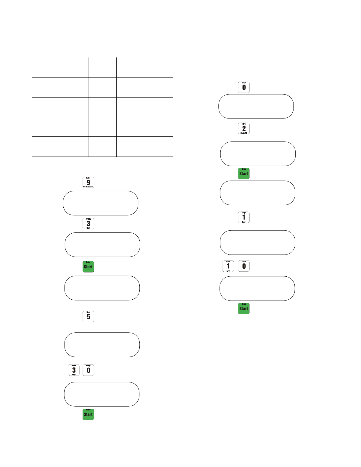
Programming
Step XX Cycle XX
Spin
Step XX Cycle XX
Spin 3
Step XX Cycle XX
0 min
Step XX Cycle XX
5 min 30 sec
Step XX Cycle XX
5 min 00 sec
Select the spin number
(example: 3).
Enter the spin time. Enter
minutes first and then
seconds (example:
5 minutes 30 seconds).
Step XX Cycle XX
Drain
Step XX Cycle XX
Drain 2
Step XX Cycle XX
0 min
Step XX Cycle XX
1 min 10 sec
Step XX Cycle XX
1 min 00 sec
Select Drain 1 or 2.
If you only have 1 drain,
you can only select 1.
Enter the drain time
(example: 1 minute
10 seconds).
Spin:
Choose between 4 preset spin speeds.
Spin 1
18-75
Models
500 500 500
100/135
Models
Models
RPM
Spin 2
650 650 650
RPM
Spin 3
800 800 750
RPM
Spin 4
1000 80 750
RPM
“Spin” is button 9.
165
200
Models
Drain:
This function drains the water.
If you have 2 drains, select which drain has to be
opened.
NOTE: With the WE-8 control, it is NOT necessary
to program a drain step before spin. The spin step
incorporates the balancing routine and draining
before beginning high speed spin (as a sub part of
the spin step). A programmed drain step will be
skipped if spin step is programmed immediately
after it.
9001889
© Copyright, Alliance Laundry Systems LLC – DO NOT COPY or TRANSMIT
13
Page 16
Programming
Program Cycle 00
Program Cycle 51
Step 01 Cycle 51
Add Cycle 51
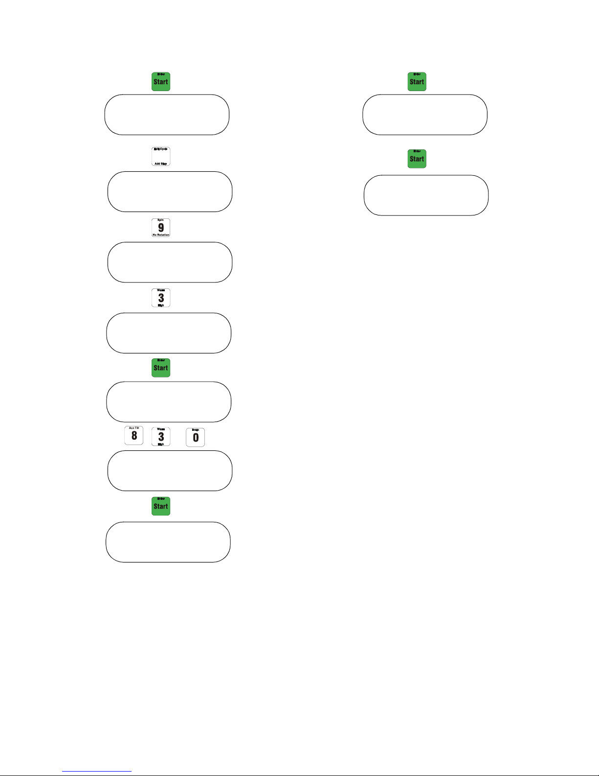
Example Making a New Program
Program 51
Step 1: Fill warm water to low level
(5 minutes 30 seconds time limit)
Step 2: Supply 1 and 5 for 20 seconds
Step 3: Heat up to 140°F (45 minutes time limit)
Step 4: Wash action 4 for 8 minutes 00 seconds
Step 5: Drain 1 for 1 minutes 25 seconds
Step 6: Spin 3 for 8 minutes 30 seconds
To program or edit cycles turn the key into the
Program Mode.
“Program Cycle xx” will be shown on the display.
14
© Copyright, Alliance Laundry Systems LLC – DO NOT COPY or TRANSMIT
9001889
Page 17
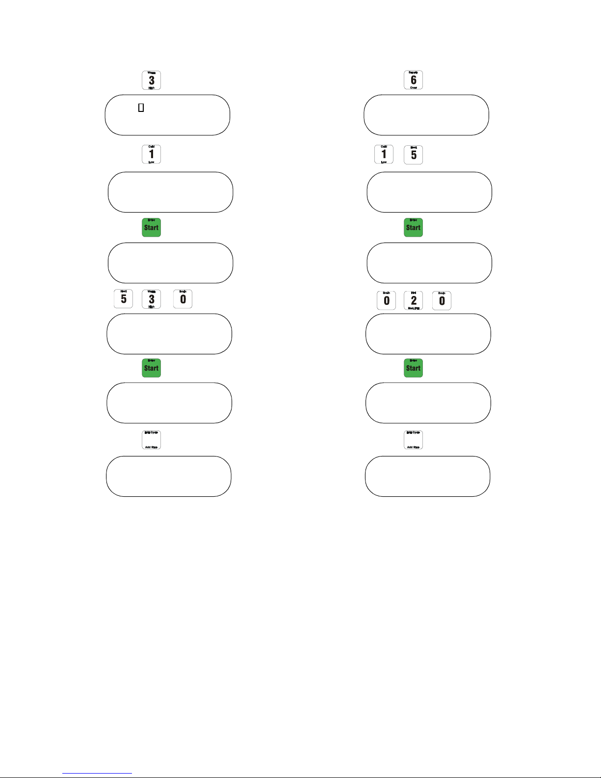
Programming
Step 01 Cycle 51
Warm
Step 01 Cycle 51
Warm Low
Step 01 Cycle 51
0 min
Step 01 Cycle 51
5 min 30 sec
End Cycle 51
Step 02 Cycle 51
Step 02 Cycle 51
Supply
Step 02 Cycle 51
Supply 1 5
Step 02 Cycle 51
0 min
Step 02 Cycle 51
0 min 20 sec
End Cycle 51
Step 03 Cycle 51
9001889
© Copyright, Alliance Laundry Systems LLC – DO NOT COPY or TRANSMIT
15
Page 18
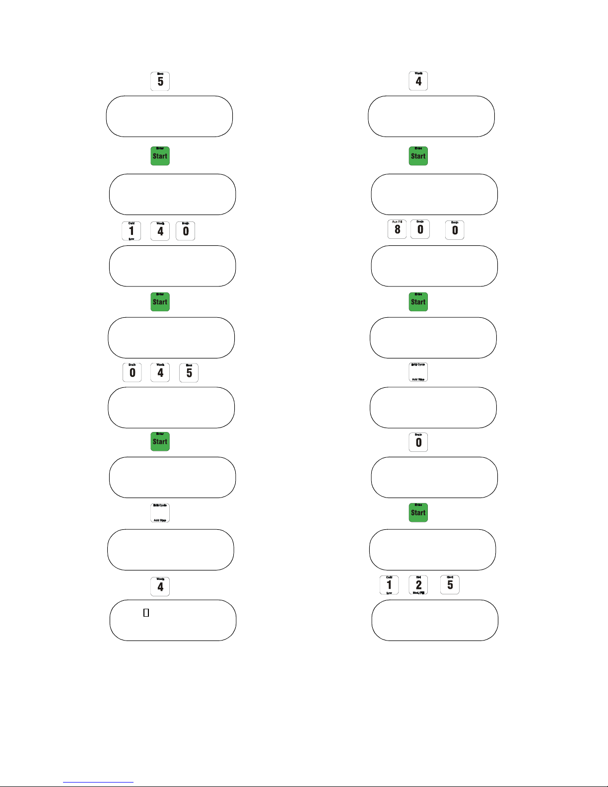
Programming
Step 03 Cycle 51
Heat
Step 03 Cycle 51
0°F
Step 03 Cycle 51
140°F
Step 03 Cycle 51
0 hours
Step 03 Cycle 51
0 hours 45 min
Step 04 Cycle 51
End Cycle 51
Step 04 Cycle 51
Wash
Step 04 Cycle 51
Wash 4 10/20
Step 04 Cycle 51
0 min
Step 04 Cycle 51
8 min 00 sec
End Cycle 51
Step 05 Cycle 51
Step 05 Cycle 51
0 min
Step 05 Cycle 51
Drain 1
Step 05 Cycle 51
1 min 25 sec
16
© Copyright, Alliance Laundry Systems LLC – DO NOT COPY or TRANSMIT
9001889
Page 19
End Cycle 51
Step 06 Cycle 51
Step 06 Cycle 51
Spin 1
Step 06 Cycle 51
Spin 3
Step 06 Cycle 51
0 min
End Cycle 51
Step 06 Cycle 51
8 min 30 sec
Enter to save ?
Program Cycle 51
Programming
9001889
© Copyright, Alliance Laundry Systems LLC – DO NOT COPY or TRANSMIT
17
Page 20

Programming
Program Cycle 00
Program Cycle 51
Edit Cycle 51
Name Cycle 51:
Cycle 51
Step 01 Cycle 51
Warm Low
Step 02 Cycle 51
Wash
Step 02 Cycle 51
Wash 1 18/3
Step 02 Cycle 51
Edit a Cycle
Change a Complete Step
To edit a cycle enter the cycle number
(example: cycle 51).
Press the “Edit Cycle” button.
Press the “Enter” button to edit the cycle.
Press “Enter” to continue.
The first step of cycle 51 will display.
Select the step being edited by using the “Advance”
button to go to the next step or the “Previous” button
to go to the previous step.
If you would like to change the step, press the “Clear”
button.
Select another wash action or press the “Clear” button
to change the function.
Fill in the function desired (example: soak for 1 hour
30 minutes).
Press the “Soak” button.
18
© Copyright, Alliance Laundry Systems LLC – DO NOT COPY or TRANSMIT
9001889
Page 21

Step 02 Cycle 51
Soak
Step 02 Cycle 51
0 hours
Step 02 Cycle 51
1 hours 00 min
Step 02 Cycle 51
1 hours 30 min
Step 03 Cycle 51
XXXXXXXX
End Cycle
Enter to save ?
Programming
The control is then in the next step of cycle 51. Press
“Advance” until the display shows “End Cycle 55”.
Press “Enter” to confirm.
Press “Enter” to save or “Stop” to ignore the changes.
9001889
© Copyright, Alliance Laundry Systems LLC – DO NOT COPY or TRANSMIT
19
Page 22

Programming
Program Cycle 00
Program Cycle 51
Edit Cycle 51
Name Cycle 51:
Cycle 51
Step 01 Cycle 51
Warm Low
Step 02 Cycle 51
Wash 1 18/3
Step 02 Cycle 51
5 min 00 sec
Step 01 Cycle 51
5 min
Changing the Time of a Step
To edit a cycle, enter the cycle number
(example: cycle 51).
Press the “Edit Cycle” button.
Press the “Enter” button to edit the cycle.
Press “Enter” to continue.
The first step of cycle 51 will display.
Select the step being edited by using the “Advance”
button to go to the next step or the “Previous” button
to go to the previous step.
20
Press “Enter” to change the time of the wash action.
Press “Clear” to change the time.
Fill in another time (example: 6 minutes 20 seconds).
© Copyright, Alliance Laundry Systems LLC – DO NOT COPY or TRANSMIT
9001889
Page 23

Step 02 Cycle 51
6 min 00 sec
Step 02 Cycle 51
6 min 20 sec
Step 03 Cycle 51
XXXXXXX
End Cycle 51
Enter to save ?
Programming
Press “Enter” to go to the next step.
Press the “Advance” button until display shows “End
Cycle 51”.
Press “Enter” to confirm.
Press “Enter” to save or “Stop” to ignore the changes.
9001889
© Copyright, Alliance Laundry Systems LLC – DO NOT COPY or TRANSMIT
21
Page 24

Programming
Program Cycle 00
Program Cycle 51
Edit Cycle 51
Name Cycle 51:
Cycle 51
Step 01 Cycle 51
Warm Low
Step 02 Cycle 51
Wash 1 18/3
Step 02 Cycle 51
Wash
Step 02 Cycle 51
Step deleted
Delete a Step
To edit a cycle, enter the cycle number
(example: cycle 51).
Press the “Edit Cycle” button.
Press the “Enter” button to edit the cycle.
Press “Enter” to continue.
The first step of cycle 51 will display.
Select the step being edited by using the “Advance”
button to go to the next step or the “Previous” button
to go to the previous step.
Press the “Clear” button to change the step.
Press the “Clear” button again.
Press the “Clear” button once more.
22
© Copyright, Alliance Laundry Systems LLC – DO NOT COPY or TRANSMIT
The step is deleted. Press the “Advance” button to end
cycle 51 and press “Enter” 2 times to save the settings.
9001889
Page 25

Program Cycle 00
Program Cycle 51
Edit Cycle 51
Name Cycle 51:
Cycle 51
Step 01 Cycle 51
Warm Low
Step 02 Cycle 51
Wash 1 18/3
Step 02 Cycle 51
Step 02 Cycle 51
Supply
Programming
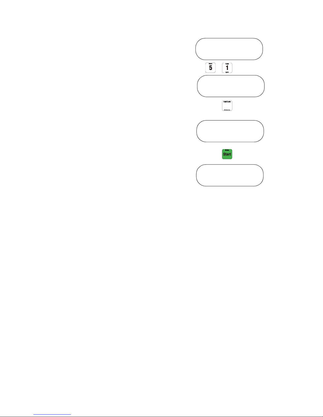
Insert a Step
To edit a cycle, enter the cycle number
(example: cycle 51).
Press the “Edit Cycle” button.
Press the “Enter” button to edit the cycle.
Press “Enter” to continue.
The first step of cycle 51 will display.
Select the position where you would like to add a step
by using the “Advance” button to go to the next step or
the “Previous” button to go to the previous step.
Push the “Add Step” button to add a step.
The control will insert a step before the step selected.
Select the function (example: supply).
9001889
© Copyright, Alliance Laundry Systems LLC – DO NOT COPY or TRANSMIT
Press the supply number (example: supply 7).
23
Page 26

Programming
Step 02 Cycle 51
Supply 7
Step 02 Cycle 51
0 min
Step 02 Cycle 51
0 min 00 sec
Step 02 Cycle 51
0 min 23 sec
Step 03 Cycle 51
Wash 1 18/3
End Cycle 51
Enter to save ?
Press “Enter” to confirm.
Enter the time to activate the supply
(example: 0 minutes 23 seconds).
Press “Enter” to confirm.
Press the “Advance” button until
“End Cycle 51” is displayed.
Press “Enter” to confirm.
Press “Enter” to save or “Stop” to ignore the changes.
24
© Copyright, Alliance Laundry Systems LLC – DO NOT COPY or TRANSMIT
9001889
Page 27

Program Cycle 00
Erase Cycle 00
Erase Cycle 55
Enter to save ?
Programming
Delete a Cycle
Press the “Erase Cycle” button.
Press the number of the cycle being erased
(example: 55).
Press “Enter” to confirm.
Press “Enter” to save or “Stop” to ignore the changes.
9001889
© Copyright, Alliance Laundry Systems LLC – DO NOT COPY or TRANSMIT
25
Page 28

Programming
Program Cycle 00
Enter to reload
earlier settings
Reloading Previous Settings
This special function allows previous settings to be
restored.
Press “Auxiliary”, “3”, “0”.
The control will ask if earlier settings are desired.
Press “Enter” to confirm the settings.
NOTE: This function only goes back to the last
programming function entered.
26
© Copyright, Alliance Laundry Systems LLC – DO NOT COPY or TRANSMIT
9001889
Page 29

Cycle Count
Program Cycle xx
RUN
PROGRAM
Program Cycle xx
Total Working
Hours 347
Tot al C y cle : 5
OR...
Programming
Reading Cycle Count
1. Enter Program Mode by turning key to
PROGRAM position (xx represents a cycle
number from 00 to 99).
2. Press “Auxiliary” key, then “3” key, then “1” key.
3. The total hours of cycle operation (actual run
time) will display. Press “Advance” key to
continue.
Example display shows 347 total hours (of all
cycles).
4. Display now shows total cycle count. Press
“Advance” key to continue into calibration
mode, or press “Clear/Stop” key to exit.
9001889
© Copyright, Alliance Laundry Systems LLC – DO NOT COPY or TRANSMIT
Example display shows 5 total cycles have been
run.
27
Page 30

Programming
Program Cycle 00
Total working
hours : 0
level : 0.0 “
Enter to zero
Spin
XXX rpm
Reference x.xx
Calibration of the Machine
The _x__PV should reflect the size selected in earlier
steps.
Turn key to Program Mode.
Press “Auxiliary”, “3”, “1”.
The total hours the machine was running will be
displayed.
Press “Advance” and screen will show total cycles.
Press “Advance” to calibrate the water level sensor.
If the value is not zero, press “Enter” and the value
will change to zero.
Press “Advance” to calibrate the motor.
The board will lock the door and let the motor spin at
approximately 500 rpm (Firmware version 1.12 or
higher). The rpm will increase on the display. If the
machine reached approximately 500 rpm, the display
will show a reference value.
After the reference value is shown, the machine will
coast down to stop. When the machine stands still, the
board will unlock the door.
28
© Copyright, Alliance Laundry Systems LLC – DO NOT COPY or TRANSMIT
9001889
Page 31

Speed Calibration
Total working
hours : #
Total Cycle:
#
Calibration
and testing
level: 0.0"
Enter to zero
If shell is empty of
water and display reads
0.0", then press “Add
Cycle/Advance”.
Motor Control
Distribute Speed
# rpm
Spin
# rpm
Calibrate 1
100 rpm
Spin
# rpm
Calibrate 2
500 rpm
Ref: #
Offset: #
Coast down
Please wait
Program Cycle #
End of Calibration
This function automatically calibrates water level,
distribution speed and spin speed.
Programming
9001889
© Copyright, Alliance Laundry Systems LLC – DO NOT COPY or TRANSMIT
29
Page 32

Pre-Programmed Cycles
Cycle 01
Sheets Light Soil
Step Description Min:sec
1 Hot Fill to Low Level 5:00
2 Supply 1, 2, 4, 5 0:45
3 Wash 1 18/3 (32°F) 7:00
4 Drain 1 1:00
5 Hot Fill to High Level 5:00
6 Wash 1 18/3 (32°F) 2:00
7 Drain 1 1:00
8Spin 1 1:00
9 100°F Fill to Low Level 5:00
10 Supply 3, 6, 7 0:30
11 Wash 1 18/3 (32°F) 4:00
12 Drain 1 1:00
Cycle 02
Sheets No Bleach
Step Description Min:sec
1 Hot Fill to Low Level 5:00
2 Supply 1, 4 0:45
3 Wash 1 18/3 (32°F) 7:00
4 Drain 1 1:00
5 Hot Fill to High Level 5:00
6 Wash 1 18/3 (32°F) 2:00
7 Drain 1 1:00
8Spin 1 1:00
9 100°F Fill to Low Level 5:00
10 Supply 3, 6, 7 0:30
11 Wash 1 18/3 (32°F) 4:00
12 Drain 1 1:00
13 Spin 1 3:00
13 Spin 1 3:00
30
© Copyright, Alliance Laundry Systems LLC – DO NOT COPY or TRANSMIT 9001889
Page 33

Pre-Programmed Cycles
Cycle 03
Towels Light Soil
Step Description Min:sec
1 Hot Fill to Low Level 5:00
2 Supply 1, 2, 4, 5 0:45
3 Wash 1 18/3 (32°F) 7:00
4Drain 1 1:00
5 Hot Fill to High Level 5:00
6 Wash 1 18/3 (32°F) 2:00
7Drain 1 1:00
8Spin 1 1:00
9 110°F Fill to Low Level 5:00
10 Supply 3, 6, 7 0:30
11 Wash 1 18/3 (32°F) 5:00
12 Drain 1 1:00
Cycle 04
Towels No Bleach
Step Description Min:sec
1 Hot Fill to Low Level 5:00
2 Supply 1, 4 0:45
3 Wash 1 18/3 (32°F) 7:00
4 Drain 1 1:00
5 Hot Fill to High Level 5:00
6 Wash 1 18/3 (32°F) 2:00
7 Drain 1 1:00
8Spin 1 1:00
9 110°F Fill to Low Level 5:00
10 Supply 3, 6, 7 0:30
11 Wash 1 18/3 (32°F) 4:00
12 Drain 1 1:00
13 Spin 4 6:00
13 Spin 4 6:00
9001889
© Copyright, Alliance Laundry Systems LLC – DO NOT COPY or TRANSMIT
31
Page 34

Pre-Programmed Cycles
Cycle 05
Sheets Medium Soil
Step Description Min:sec
1 Hot Fill to Low Level 5:00
2 Supply 1, 4 0:45
3 Wash 1 18/3 (32°F) 6:00
4 Drain 1 1:00
5 Hot Fill to Low Level 5:00
6 Supply 2, 5 0:45
7 Wash 1 18/3 (32°F) 6:00
8 Drain 1 1:00
9 Hot Fill to High Level 5:00
10 Wash 1 18/3 (32°F) 2:00
11 Drain 1 1:00
12 Spin 1 1:00
Cycle 06
Towels Medium Soil
Step Description Min:sec
1 Hot Fill to Low Level 5:00
2 Supply 1, 4 0:45
3 Wash 1 18/3 (32°F) 6:00
4Drain 1 1:00
5 Hot Fill to Low Level 5:00
6 Supply 2, 5 0:45
7 Wash 1 18/3 (32°F) 6:00
8Drain 1 1:00
9 Hot Fill to High Level 5:00
10 Wash 1 18/3 (32°F) 2:00
11 Drain 1 1:00
12 Spin 1 1:00
13 100°F Fill to Low Level 5:00
14 Supply 3, 6, 7 0:30
15 Wash 1 18/3 (32°F) 4:00
16 Drain 1 1:00
17 Spin 1 3:00
13 110°F Fill to Low Level 5:00
14 Supply 3, 6, 7 0:30
15 Wash 1 18/3 (32°F) 4:00
16 Drain 1 1:00
17 Spin 4 6:00
32
© Copyright, Alliance Laundry Systems LLC – DO NOT COPY or TRANSMIT
9001889
Page 35

Pre-Programmed Cycles
Cycle 07
Blankets Warm
Step Description Min:sec
1 Warm Fill to High Level 5:00
2 Supply 1, 4 0:45
3 Wash 1 18/3 (32°F) 6:00
4 Drain 1 1:00
5 Warm Fill to High Level 5:00
6 Wash 1 18/3 (32°F) 5:00
7 Drain 1 1:00
8Spin 1 1:00
9 Warm Fill to Low Level 5:00
10 Supply 3, 6, 7 0:30
11 Wash 2 3/27 (32°F) 4:00
12 Drain 1 1:00
Cycle 08
Spreads Cold
Step Description Min:sec
1 Cold Fill to High Level 5:00
2 Supply 1, 4 0:45
3 Wash 2 3/27 (32°F) 6:00
4 Drain 1 1:00
5 Cold Fill to High Level 5:00
6 Wash 2 3/27 (32°F) 1:30
7 Drain 1 1:00
8Spin 1 1:00
9 Cold Fill to High Level 5:00
10 Supply 3, 6, 7 0:30
11 Wash 2 3/27 (32°F) 4:00
12 Drain 1 1:00
13 Spin 4 4:00
13 Spin 4 4:00
9001889
© Copyright, Alliance Laundry Systems LLC – DO NOT COPY or TRANSMIT
33
Page 36

Pre-Programmed Cycles
Cycle 09
Towels Heavy Soil
Step Description Min:sec
1 Hot Fill to Low Level 5:00
2 Supply 1, 4 0:45
3 Wash 1 18/3 (32°F) 7:00
4 Hot Fill to High Level 5:00
5 Supply 2, 5 1:00
6 Wash 1 18/3 (32°F) 7:00
7Drain 1 1:00
8Spin 1 1:00
9 Warm Fill to High Level 5:00
10 Wash 1 18/3 (32°F) 2:00
11 Drain 1 1:00
12 Spin 1 1:00
Cycle 10
Rinse and Spin
Step Description Min:sec
1 Warm Fill to Low Level 5:00
2 Wash 1 18/3 (32°F) 1:00
3Drain 1 1:00
4Spin 1 1:00
5Spin 4 4:00
13 Warm Fill to Low Level 5:00
14 Supply 3, 6, 7 1:00
15 Wash 1 18/3 (32°F) 4:00
16 Drain 1 1:00
17 Spin 4 6:00
34
© Copyright, Alliance Laundry Systems LLC – DO NOT COPY or TRANSMIT
9001889
Page 37

Pre-Programmed Cycles
Cycle 11
Health Care Sheets Light Soil
Step Description Min:sec
1 Warm Fill to High Level 5:00
2 Wash 1 18/3 (32°F) 2:00
3 Drain 1, 2, 4, 5 1:00
4 Hot Fill to Low Level 5:00
5 Supply 1, 2 0:45
6 Wash 1 18/3 (32°F) 8:00
7Drain 1 1:00
8 Hot Fill to High Level 5:00
9 Wash 1 18/3 (32°F) 3:00
10 Drain 1 1:00
11 Spin 1 1:00
12 100°F Fill to Low Level 5:00
Cycle 12
Health Care Towels Light Soil
Step Description Min:sec
1 Warm Fill to High Level 5:00
2 Wash 1 18/3 (32°F) 2:00
3Drain 1 1:00
4 Hot Fill to Low Level 5:00
5 Supply 1, 2, 4, 5 0:45
6 Wash 1 18/3 (32°F) 8:00
7Drain 1 1:00
8 Hot Fill to High Level 5:00
9 Wash 1 18/3 (32°F) 3:00
10 Drain 1 1:00
11 Spin 1 1:00
12 110°F Fill to Low Level 5:00
13 Supply 3, 6, 7 0:30
14 Wash 1 18/3 (32°F) 4:00
15 Drain 1 1:00
16 Spin 1 4:00
13 Supply 3, 6, 7 0:30
14 Wash 1 18/3 (32°F) 4:00
15 Drain 1 1:00
16 Spin 4 4:00
9001889
© Copyright, Alliance Laundry Systems LLC – DO NOT COPY or TRANSMIT
35
Page 38

Pre-Programmed Cycles
Cycle 13
Health Care Sheets Heavy Soil
Step Description Min:sec
1 32°F Fill to High Level 5:00
2 Wash 1 18/3 (32°F) 2:00
3Drain 1 1:00
4 120°F Fill to High Level 5:00
5 Wash 1 18/3 (32°F) 2:00
6Drain 1, 4 1:00
7 Hot Fill to Low Level 5:00
8 Supply 1 0:45
9 Wash 1 18/3 (32°F) 7:00
10 Drain 1 1:00
11 Hot Fill to Low Level 5:00
12 Supply 2, 5 0:45
Cycle 14
Health Care Towels Heavy Soil
Step Description Min:sec
1 32°F Fill to High Level 5:00
2 Wash 1 18/3 (32°F) 2:00
3 Drain 1 1:00
4 120°F Fill to High Level 5:00
5 Wash 1 18/3 (32°F) 2:00
6 Drain 1 1:00
7 Hot Fill to Low Level 5:00
8 Supply 1, 4 0:45
9 Wash 1 18/3 (32°F) 7:00
10 Drain 1 1:00
11 Hot Fill to Low Level 5:00
12 Supply 2, 5 0:45
13 Wash 1 18/3 (32°F) 7:00
14 Drain 1 1:00
15 Hot Fill to High Level 5:00
16 Wash 1 18/3 (32°F) 3:00
17 Drain 1 1:00
18 Spin 1 1:00
19 100°F Fill to Low Level 5:00
20 Supply 3, 6, 7 0:30
21 Wash 1 18/3 (32°F) 4:00
22 Drain 1 1:00
23 Spin 1 3:00
13 Wash 1 18/3 (32°F) 7:00
14 Drain 1 1:00
15 Hot Fill to High Level 5:00
16 Wash 1 18/3 (32°F) 3:00
17 Drain 1 1:00
18 Spin 1 1:00
19 110°F Fill to Low Level 5:00
20 Supply 3, 6, 7 0:30
21 Wash 1 18/3 (32°F) 4:00
22 Drain 1 1:00
23 Spin 4 6:00
36
© Copyright, Alliance Laundry Systems LLC – DO NOT COPY or TRANSMIT
9001889
Page 39

Pre-Programmed Cycles
Cycle 15
Health Care Cotton Blankets
Step Description Min:sec
1 110°F Fill to High Level 5:00
2 Wash 1 18/3 (32°F) 2:00
3 Drain 1 1:00
4 Hot Fill to Low Level 5:00
5 Supply 1, 2, 4, 5 0:45
6 Wash 1 18/3 (32°F) 7:00
7 Drain 1 1:00
8 Hot Fill to High Level 5:00
9 Wash 1 18/3 (32°F) 3:00
10 Drain 1 1:00
11 Spin 1 1:00
12 110°F Fill to Low Level 5:00
13 Supply 3, 6, 7 0:30
Cycle 16
Health Care Diapers Heavy Soil
Step Description Min:sec
1 32°F Fill to High Level 5:00
2 Wash 1 18/3 (32°F) 2:00
3 Drain 1 1:00
4 Hot Fill to High Level 5:00
5 Wash 1 18/3 (32°F) 2:00
6 Drain 1 1:00
7 Hot Fill to Low Level 5:00
8 Supply 1, 4 0:45
9 Wash 1 18/3 (32°F) 7:00
10 Drain 1 1:00
11 Hot Fill to Low Level 5:00
12 Supply 1, 4 0:30
13 Wash 1 18/3 (32°F) 7:00
14 Wash 1 18/3 (32°F) 4:00
15 Drain 1 1:00
16 Spin 4 6:00
14 Drain 1 1:00
15 Hot Fill to Low Level 5:00
16 Supply 2, 5 0:30
17 Wash 1 18/3 (32°F) 7:00
18 Drain 1 1:00
19 Hot Fill to High Level 5:00
20 Wash 1 18/3 (32°F) 4:00
21 Drain 1 1:00
22 Spin 1 2:00
23 110°F Fill to High Level 5:00
24 Wash 1 18/3 (32°F) 2:00
25 Drain 1 1:00
26 110°F Fill to Low Level 5:00
27 Supply 3, 6, 7 0:30
28 Wash 1 18/3 (32°F) 4:00
9001889
© Copyright, Alliance Laundry Systems LLC – DO NOT COPY or TRANSMIT
29 Drain 1 1:00
30 Spin 1 1:00
31 Spin 4 6:00
37
Page 40

Pre-Programmed Cycles
Cycle 17
Health Care Personal Bleach
Step Description Min:sec
1 Hot Fill to Low Level 5:00
2 Supply 1, 2, 4, 5 0:45
3 Wash 1 18/3 (32°F) 6:00
4 Drain 1 1:00
5 Hot Fill to High Level 5:00
6 Wash 1 18/3 (32°F) 2:00
7 Drain 1 1:00
8Spin 1 1:00
9 110°F Fill to Low Level 5:00
10 Supply 3, 6, 7 0:30
11 Wash 1 18/3 (32°F) 4:00
12 Drain 1 1:00
Cycle 18
Health Care Personal No Bleach
Step Description Min:sec
1 Hot Fill to Low Level 5:00
2 Supply 1, 4 0:45
3 Wash 1 18/3 (32°F) 6:00
4 Drain 1 1:00
5 110°F Fill to High Level 5:00
6 Wash 1 18/3 (32°F) 2:00
7 Drain 1 1:00
8Spin 1 1:00
9 110°F Fill to Low Level 5:00
10 Supply 3, 6, 7 0:30
11 Wash 1 18/3 (32°F) 4:00
12 Drain 1 1:00
13 Spin 1 3:00
13 Spin 1 3:00
38
© Copyright, Alliance Laundry Systems LLC – DO NOT COPY or TRANSMIT
9001889
Page 41

Pre-Programmed Cycles
Cycle 19
Health Care Pads Polyester
Step Description Min:sec
1 110°F Fill to Low Level 5:00
2 Supply 1, 4 0:45
3 Wash 1 18/3 (32°F) 3:00
4 130°F Fill to High Level 5:00
5 Wash 1 18/3 (32°F) 2:00
6 Drain 1 1:00
7 Hot Fill to Low Level 5:00
8 Supply 1, 4 0:45
9 Wash 1 18/3 (32°F) 7:00
10 Drain 1 1:00
11 Hot Fill to Low Level 5:00
12 Supply 2, 5 0:45
Cycle 20
Table Linen Iron
Step Description Min:sec
1 110°F Fill to High Level 5:00
2 Wash 1 18/3 (32°F) 2:00
3 Drain 1 1:00
4 Hot Fill to Low Level 5:00
5 Supply 1, 4 0:45
6 Wash 1 18/3 (32°F) 7:00
7 Drain 1 1:00
8 Hot Fill to Low Level 5:00
9 Supply 2, 5 0:45
10 Wash 1 18/3 (32°F) 7:00
11 Drain 1 1:00
12 Hot Fill to High Level 5:00
13 Wash 1 18/3 (32°F) 7:00
14 Drain 1 1:00
15 Spin 1 1:00
16 110°F Fill to High Level 5:00
17 Wash 1 18/3 (32°F) 2:00
18 Drain 1 1:00
19 Spin 1 1:00
20 110°F Fill to Low Level 5:00
21 Supply 3, 6, 7 0:30
22 Wash 1 18/3 (32°F) 3:00
23 Drain 1 1:00
24 Spin 4 4:00
13 Wash 1 18/3 (32°F) 3:00
14 Drain 1 1:00
15 Spin 1 1:00
16 110°F Fill to Low Level 5:00
17 Supply 3, 6 0:30
18 Wash 1 18/3 (32°F) 2:00
19 Supply 6, 8 0:30
20 Wash 1 18/3 (32°F) 5:00
21 Drain 1 1:00
22 Spin 2 4:00
9001889
© Copyright, Alliance Laundry Systems LLC – DO NOT COPY or TRANSMIT
39
Page 42

Pre-Programmed Cycles
Cycle 21
Table Linen No Iron
Step Description Min:sec
1 110°F Fill to High Level 5:00
2 Wash 1 18/3 (32°F) 2:00
3Drain 1 1:00
4 Hot Fill to Low Level 5:00
5 Supply 1, 4 0:45
6 Wash 1 18/3 (32°F) 7:00
7Drain 1 1:00
8 Hot Fill to Low Level 5:00
9 Supply 2, 5 0:45
10 Wash 1 18/3 (32°F) 7:00
11 Drain 1 1:00
12 Hot Fill to High Level 5:00
Cycle 22
Table Color Iron
Step Description Min:sec
1 110°F Fill to High Level 5:00
2 Wash 1 18/3 (32°F) 2:00
3 Drain 1 1:00
4 Hot Fill to Low Level 5:00
5 Supply 1, 4 0:45
6 Wash 1 18/3 (32°F) 7:00
7 Drain 1 1:00
8 Hot Fill to Low Level 5:00
9 Supply 1, 4 0:45
10 Wash 1 18/3 (32°F) 7:00
11 Drain 1 1:00
12 Hot Fill to High Level 5:00
13 Wash 1 18/3 (32°F) 3:00
14 Drain 1 1:00
15 Spin 1 1:00
16 110°F Fill to Low Level 5:00
17 Supply 3, 6, 7 0:30
18 Wash 1 18/3 (32°F) 4:00
19 Drain 1 1:00
20 Spin 1 3:00
13 Wash 1 18/3 (32°F) 3:00
14 Drain 1 1:00
15 Spin 1 1:00
16 110°F Fill to Low Level 5:00
17 Supply 3, 6 0:30
18 Wash 1 18/3 (32°F) 4:00
19 Supply 8 0:30
20 Wash 1 18/3 (32°F) 5:00
21 Drain 1 1:00
22 Spin 2 4:00
40
© Copyright, Alliance Laundry Systems LLC – DO NOT COPY or TRANSMIT
9001889
Page 43

Pre-Programmed Cycles
Cycle 23
Table Color No Iron
Step Description Min:sec
1 110°F Fill to High Level 5:00
2 Wash 1 18/3 (32°F) 2:00
3 Drain 1 1:00
4 Hot Fill to Low Level 5:00
5 Supply 1, 4 0:45
6 Wash 1 18/3 (32°F) 7:00
7 Drain 1 1:00
8 Hot Fill to Low Level 5:00
9 Supply 1, 4 0:45
10 Wash 1 18/3 (32°F) 7:00
11 Drain 1 1:00
12 Hot Fill to High Level 5:00
Cycle 24
Visa Iron
Step Description Min:sec
1 110°F Fill to High Level 5:00
2 Wash 1 18/3 (32°F) 3:00
3 Drain 1 1:00
4 Hot Fill to Low Level 5:00
5 Supply 1, 4 0:45
6 Wash 1 18/3 (32°F) 7:00
7 Drain 1 1:00
8 Hot Fill to Low Level 5:00
9 Supply 2, 5 0:45
10 Wash 1 18/3 (32°F) 7:00
11 Drain 1 1:00
12 Hot Fill to High Level 5:00
13 Wash 1 18/3 (32°F) 3:00
14 Drain 1 1:00
15 Spin 1 1:00
16 110°F Fill to Low Level 5:00
17 Supply 3, 6, 7 0:30
18 Wash 1 18/3 (32°F) 4:00
19 Drain 1 1:00
20 Spin 1 4:00
13 Wash 1 18/3 (32°F) 3:00
14 Drain 1 1:00
15 Spin 1 1:00
16 110°F Fill to High Level 5:00
17 Wash 1 18/3 (32°F) 2:00
18 Drain 1 1:00
19 110°F Fill to Low Level 5:00
20 Supply 3, 6 0:30
21 Wash 1 18/3 (32°F) 2:00
22 Supply 8 0:30
23 Wash 1 18/3 (32°F) 5:00
24 Drain 1 1:00
25 Spin 2 3:00
9001889
© Copyright, Alliance Laundry Systems LLC – DO NOT COPY or TRANSMIT
41
Page 44

Pre-Programmed Cycles
Cycle 25
Visa No Iron
Step Description Min:sec
1 110°F Fill to High Level 5:00
2 Wash 1 18/3 (32°F) 3:00
3 Drain 1 1:00
4 Hot Fill to Low Level 5:00
5 Supply 1, 4 0:45
6 Wash 1 18/3 (32°F) 7:00
7 Drain 1 1:00
8 Hot Fill to Low Level 5:00
9 Supply 2, 5 0:45
10 Wash 1 18/3 (32°F) 7:00
11 Drain 1 1:00
12 Hot Fill to High Level 5:00
Cycle 26
Visa Color Iron
Step Description Min:sec
1 110°F Fill to High Level 5:00
2 Wash 1 18/3 (32°F) 3:00
3 Drain 1, 4 1:00
4 Hot Fill to Low Level 5:00
5Supply 1 0:45
6 Wash 1 18/3 (32°F) 7:00
7 Drain 1 1:00
8 Hot Fill to Low Level 5:00
9 Supply 1, 4 0:45
10 Wash 1 18/3 (32°F) 7:00
11 Drain 1 1:00
12 Hot Fill to High Level 5:00
13 Wash 1 18/3 (32°F) 3:00
14 Drain 1 1:00
15 Spin 1 1:00
16 110°F Fill to High Level 5:00
17 Wash 1 18/3 (32°F) 2:00
18 Drain 1 1:00
19 110°F Fill to Low Level 5:00
20 Supply 3, 6 0:30
21 Wash 1 18/3 (32°F) 4:00
22 Drain 1 1:00
23 Spin 1 3:00
13 Wash 1 18/3 (32°F) 3:00
14 Drain 1 1:00
15 Spin 1 1:00
16 110°F Fill to High Level 5:00
17 Wash 1 18/3 (32°F) 2:00
18 Drain 1 1:00
19 110°F Fill to Low Level 5:00
20 Supply 3, 6 0:30
21 Wash 1 18/3 (32°F) 2:00
22 Supply 8 0:30
23 Wash 1 18/3 (32°F) 4:00
24 Drain 1 1:00
25 Spin 2 3:00
42
© Copyright, Alliance Laundry Systems LLC – DO NOT COPY or TRANSMIT
9001889
Page 45

Pre-Programmed Cycles
Cycle 27
Visa Color No Iron
Step Description Min:sec
1 110°F Fill to High Level 5:00
2 Wash 1 18/3 (32°F) 3:00
3 Drain 1 1:00
4 Hot Fill to Low Level 5:00
5 Supply 1, 4 0:45
6 Wash 1 18/3 (32°F) 7:00
7 Drain 1 1:00
8 Hot Fill to Low Level 5:00
9 Supply 1, 4 0:45
10 Wash 1 18/3 (32°F) 7:00
11 Drain 1 1:00
12 Hot Fill to High Level 5:00
Cycle 28
Shirt Color Starch
Step Description Min:sec
1 Hot Fill to Low Level 5:00
2 Supply 1, 4 0:45
3 Wash 1 18/3 (32°F) 7:00
4Drain 1 1:00
5 Hot Fill to Low Level 5:00
6 Supply 1, 4 0:45
7 Wash 1 18/3 (32°F) 5:00
8Drain 1 1:00
9 Hot Fill to High Level 5:00
10 Wash 1 18/3 (32°F) 3:00
11 Drain 1 1:00
12 Spin 1 1:00
13 Wash 1 18/3 (32°F) 3:00
14 Drain 1 1:00
15 Spin 1 1:00
16 110°F Fill to High Level 5:00
17 Wash 1 18/3 (32°F) 2:00
18 Drain 1 1:00
19 110°F Fill to Low Level 5:00
20 Supply 3, 6 0:30
21 Wash 1 18/3 (32°F) 4:00
22 Drain 1 1:00
23 Spin 1 3:00
13 Cold Fill to High Level 5:00
14 Supply 3, 6 0:30
15 Supply 5 0:30
16 Wash 1 18/3 (32°F) 4:00
17 Drain 1 1:00
18 Spin 2 3:00
9001889
© Copyright, Alliance Laundry Systems LLC – DO NOT COPY or TRANSMIT
43
Page 46

Pre-Programmed Cycles
Cycle 29
Shirt Bleach Starch
Step Description Min:sec
1 Hot Fill to Low Level 5:00
2 Supply 1, 4 0:45
3 Wash 1 18/3 (32°F) 7:00
4Drain 1 1:00
5 Hot Fill to Low Level 5:00
6 Supply 2, 5 0:45
7 Wash 1 18/3 (32°F) 7:00
8Drain 1 1:00
9 Hot Fill to High Level 5:00
10 Wash 1 18/3 (32°F) 3:00
11 Drain 1 1:00
12 Spin 1 1:00
Cycle 30
Shirt Color No Bleach
Step Description Min:sec
1 Hot Fill to Low Level 5:00
2 Supply 1, 4 0:45
3 Wash 1 18/3 (32°F) 7:00
4 Drain 1 1:00
5 Hot Fill to Low Level 5:00
6 Supply 1, 4 0:45
7 Wash 1 18/3 (32°F) 5:00
8 Drain 1 1:00
9 Hot Fill to High Level 5:00
10 Wash 1 18/3 (32°F) 3:00
11 Drain 1 1:00
12 Spin 1 1:00
13 Cold Fill to High Level 5:00
14 Supply 3, 6 0:30
15 Supply 2, 8 0:30
16 Wash 1 18/3 (32°F) 4:00
17 Drain 1 1:00
18 Spin 2 3:00
13 Cold Fill to High Level 5:00
14 Supply 3, 6 0:30
15 Supply 4 0:30
16 Wash 1 18/3 (32°F) 4:00
17 Drain 1 1:00
18 Spin 2 3:00
44
© Copyright, Alliance Laundry Systems LLC – DO NOT COPY or TRANSMIT
9001889
Page 47

Pre-Programmed Cycles
Cycle 31
Shirt Delicate
Step Description Min:sec
1 Warm Fill to Low Level 5:00
2 Wash 2 3/27 (32°F) 2:00
3Drain 1 1:00
4 Warm Fill to Low Level 5:00
5 Supply 1, 4 0:45
6 Wash 2 3/27 (32°F) 5:00
7Drain 1 1:00
8 Warm Fill to High Level 5:00
9 Wash 2 3/27 (32°F) 2:00
10 Drain 1 1:00
11 Warm Fill to High Level 5:00
12 Wash 2 3/27 (32°F) 2:00
Cycle 32
Starch Extract
Step Description Min:sec
1 Warm Fill to Low Level 5:00
2 Supply 2, 8 0:30
3 Wash 1 18/3 (32°F) 7:00
4Drain 1 1:00
5Spin 2 3:00
13 Drain 1 1:00
14 Cold Fill to High Level 5:00
15 Supply 3, 6, 7 0:30
16 Supply 4 0:30
17 Wash 2 3/27 (32°F) 3:00
18 Drain 1 1:00
19 Spin 2 1:30
9001889
© Copyright, Alliance Laundry Systems LLC – DO NOT COPY or TRANSMIT
45
Page 48

Pre-Programmed Cycles
Cycle 33
Uniforms Bleach
Step Description Min:sec
1 110°F Fill to High Level 5:00
2 Wash 1 18/3 (32°F) 3:00
3Drain 1 1:00
4 Hot Fill to Low Level 5:00
5 Supply 1, 4 0:45
6 Wash 1 18/3 (32°F) 7:00
7Drain 1 1:00
8 Hot Fill to Low Level 5:00
9 Supply 2, 5 0:45
10 Wash 1 18/3 (32°F) 7:00
11 Drain 1 1:00
12 Hot Fill to High Level 5:00
Cycle 34
Uniforms No Bleach
Step Description Min:sec
1 Hot Fill to Low Level 5:00
2 Supply 1, 4 0:45
3 Wash 1 18/3 (32°F) 6:00
4 Drain 1 1:00
5 110°F Fill to Low Level 5:00
6 Wash 1 18/3 (32°F) 2:00
7 Drain 1 1:00
8Spin 1 1:00
9 110°F Fill to Low Level 5:00
10 Supply 3, 6, 7 0:30
11 Wash 1 18/3 (32°F) 4:00
12 Drain 1 1:00
13 Wash 1 18/3 (32°F) 3:00
14 Drain 1 1:00
15 Spin 1 1:00
16 110°F Fill to High Level 5:00
17 Wash 1 18/3 (32°F) 2:00
18 Drain 1 1:00
19 110°F Fill to Low Level 5:00
20 Supply 3, 6, 7 0:30
21 Wash 1 18/3 (32°F) 4:00
22 Drain 1 1:00
23 Spin 1 3:00
13 Spin 1 3:00
46
© Copyright, Alliance Laundry Systems LLC – DO NOT COPY or TRANSMIT
9001889
Page 49

Pre-Programmed Cycles
Cycle 35
Rags Heavy Soil
Step Description Min:sec
1 110°F Fill to High Level 5:00
2 Wash 1 18/3 (32°F) 2:00
3 Drain 1 1:00
4 Hot Fill to Low Level 5:00
5 Supply 1, 4 0:45
6 Wash 1 18/3 (32°F) 7:00
7 Drain 1 1:00
8 Hot Fill to Low Level 5:00
9 Supply 2, 5 0:45
10 Wash 1 18/3 (32°F) 7:00
11 Drain 1 1:00
12 Hot Fill to High Level 5:00
Cycle 36
Mops in Bags
Step Description Min:sec
1 110°F Fill to High Level 5:00
2 Wash 1 18/3 (32°F) 2:00
3Drain 1 1:00
4 Hot Fill to Low Level 5:00
5 Supply 1, 4 0:45
6 Wash 1 18/3 (32°F) 7:00
7Drain 1 1:00
8 Hot Fill to Low Level 5:00
9 Supply 2, 5 0:45
10 Wash 1 18/3 (32°F) 7:00
11 Drain 1 1:00
12 Hot Fill to High Level 5:00
13 Wash 1 18/3 (32°F) 2:00
14 Drain 1 1:00
15 Spin 1 1:00
16 110°F Fill to Low Level 5:00
17 Supply 3, 6 0:30
18 Wash 1 18/3 (32°F) 4:00
19 Drain 1 1:00
20 Spin 4 6:00
13 Wash 1 18/3 (32°F) 2:00
14 Drain 1 1:00
15 Spin 1 1:00
16 110°F Fill to Low Level 5:00
17 Supply 3, 6 0:30
18 Wash 1 18/3 (32°F) 4:00
19 Drain 1 1:00
20 Spin 4 4:00
9001889
© Copyright, Alliance Laundry Systems LLC – DO NOT COPY or TRANSMIT
47
Page 50

Pre-Programmed Cycles
Cycle 37
Rewash/Reclaim
Step Description Min:sec
1 130°F Fill to High Level 5:00
2 Wash 1 18/3 (32°F) 2:00
3 Drain 1 1:00
4 Hot Fill to Low Level 5:00
5 Supply 1, 2, 4, 5 0:45
6 Wash 1 18/3 (32°F) 4:00
7 Drain 1 1:00
8 Hot Fill to Low Level 5:00
9 Supply 1, 2, 4, 5 0:45
10 Wash 1 18/3 (32°F) 7:00
11 Drain 1 1:00
12 Hot Fill to High Level 5:00
Cycle 38
Supply Setup
Step Description Min:sec
1 Warm Fill to Low Level 5:00
2Supply 1 2:00
3Supply 2 2:00
4Supply 3 2:00
5Supply 4 2:00
6Supply 5 2:00
7Drain 1 1:00
8 Warm Fill to Low Level 5:00
9Supply 6 2:00
10 Supply 7 2:00
11 Supply 8 2:00
12 Supply 9 2:00
13 Wash 1 18/3 (32°F) 4:00
14 Drain 1 1:00
15 Spin 1 1:00
16 110°F Fill to High Level 5:00
17 Wash 1 18/3 (32°F) 2:00
18 Drain 1 1:00
19 110°F Fill to High Level 5:00
20 Supply 3, 6 0:30
21 Wash 1 18/3 (32°F) 4:00
22 Supply 3, 6 0:30
23 Wash 1 18/3 (32°F) 4:00
24 Drain 1 1:00
25 Spin 4 4:00
13 Wash 1 18/3 (32°F) 0:30
14 Drain 1 1:00
48
© Copyright, Alliance Laundry Systems LLC – DO NOT COPY or TRANSMIT
9001889
Page 51

Pre-Programmed Cycles
Cycle 39
Test Program
Step Description Min:sec
1 Cold Fill to High Level 0:30
2 Drain 1 0:10
3 Hot Fill to Low Level 5:00
4 Auxiliary Fill to Med Level 5:00
5Heat (150°F) 1h00
6 Cold Fill to High Level 5:00
7 Supply 1 0:30
8 Supply 2 0:30
9 Supply 3 0:30
10 Supply 4 0:30
11 Supply 5 0:30
12 Drain 1 1:00
13 Warm Fill to Low Level 0:30
14 Supply 6 0:30
15 Supply 7 0:30
Cycle 39
Test Program
Step Description Min:sec
36 Wash 1 18/3 (32°F) 0:15
37 Drain 1 1:00
16 Supply 8 0:30
17 Supply 9 0:30
18 Wash 2 3/27 (32°F) 0:30
19 Wash 3, no agitation (32°F) 0:30
20 Wash 4 10/3 (32°F) 0:30
21 Wash 1, no reverse (32°F) 0:30
22 Drain 1 1:00
23 Auxiliary 1 0:05
24 Auxiliary 2 0:05
25 Auxiliary 3 0:05
26 150°F Fill to High Level 5:00
27 Cold Fill to Overflow 5:00
28 Soak (150°F) 2h00
29 Drain 1 1:00
30 Spin 1 2:00
31 Spin 2 2:00
32 Spin 3 2:00
33 Spin 4 2:00
34 Auxiliary 3 0:15
35 Cold Fill to Med Level 5:00
9001889
© Copyright, Alliance Laundry Systems LLC – DO NOT COPY or TRANSMIT
49
Page 52

Pre-Programmed Cycles
Cycle 40
Energy Hot
Step Description Min:sec
1 Hot Fill to Low Level 5:00
2 Supply 1, 2 0:15
3 Wash 1 18/3 (32°F) 4:00
4Drain 1 1:00
5 Cold Fill to High Level 5:00
6 Wash 1 18/3 (32°F) 2:00
7Drain 1 1:00
8 Cold Fill to High Level 5:00
9 Supply 3 0:15
10 Wash 1 18/3 (32°F) 2:00
11 Spin 4 3:00
Cycle 41
Energy Warm
Step Description Min:sec
1 Warm Fill to Low Level 5:00
2 Supply 1, 2 0:15
3 Wash 1 18/3 (32°F) 4:00
4Drain 1 1:00
5 Cold Fill to High Level 5:00
6 Wash 1 18/3 (32°F) 2:00
7Drain 1 1:00
8 Cold Fill to High Level 5:00
9Supply 3 0:15
10 Wash 1 18/3 (32°F) 2:00
11 Spin 4 3:00
50
© Copyright, Alliance Laundry Systems LLC – DO NOT COPY or TRANSMIT
9001889
Page 53

Pre-Programmed Cycles
Cycle 42
Energy Cold
Step Description Min:sec
1 Cold Fill to Low Level 5:00
2 Supply 1, 2 0:15
3 Wash 1 18/3 (32°F) 4:00
4Drain 1 1:00
5 Cold Fill to High Level 5:00
6 Wash 1 18/3 (32°F) 2:00
7Drain 1 1:00
8 Cold Fill to High Level 5:00
9 Supply 3 0:15
10 Wash 1 18/3 (32°F) 2:00
11 Spin 4 3:00
Cycle 50
Normal 95°C
Step Description Min:sec
1 Warm Fill to Low Level 5:00
2 Supply 1, 4 0:30
3 Heat (104°F) 1h00
4 Wash 1 18/3 (32°F) 2:00
5Drain 1 1:00
6 Hot Fill to Low Level 5:00
7 Supply 1, 2, 4, 5 0:30
8 Heat (203°F) 1h00
9 Wash 1 18/3 (32°F) 6:00
10 Cold Fill to High Level 5:00
11 Wash 1 18/3 (32°F) 2:00
12 Drain 1 1:00
13 Cold Fill to High Level 5:00
14 Wash 1 18/3 (32°F) 2:00
15 Drain 1 1:00
16 Cold Fill to High Level 5:00
17 Wash 1 18/3 (32°F) 2:00
18 Drain 1 1:00
19 Cold Fill to High Level 5:00
20 Wash 1 18/3 (32°F) 2:00
21 Drain 1 1:00
22 Spin 1 1:00
23 Cold Fill to High Level 5:00
24 Supply 3, 6, 7 0:30
25 Wash 1 18/3 (32°F) 3:00
26 Drain 1 1:00
27 Spin 4 5:00
9001889
© Copyright, Alliance Laundry Systems LLC – DO NOT COPY or TRANSMIT
51
Page 54

Pre-Programmed Cycles
Cycle 51
Normal 60°C
Step Description Min:sec
1 Warm Fill to Low Level 5:00
2 Supply 1, 4 0:30
3Heat (104°F) 1h00
4 Wash 1 18/3 (32°F) 2:00
5Drain 1 1:00
6 Hot Fill to Low Level 5:00
7 Supply 1, 2, 4, 5 0:30
8Heat (140°F) 1h00
9 Wash 1 18/3 (32°F) 6:00
10 Cold Fill to High Level 5:00
11 Wash 1 18/3 (32°F) 2:00
12 Drain 1 1:00
Cycle 52
Normal 40°C
Step Description Min:sec
1 Warm Fill to Low Level 5:00
2 Supply 1, 4 0:30
3 Heat (104°F) 1h00
4 Wash 1 18/3 (32°F) 2:00
5Drain 1 1:00
6 Hot Fill to Low Level 5:00
7 Supply 1, 2, 4, 5 0:30
8 Heat (104°F) 1h00
9 Wash 1 18/3 (32°F) 6:00
10 Cold Fill to High Level 5:00
11 Wash 1 18/3 (32°F) 2:00
12 Drain 1 1:00
13 Cold Fill to High Level 5:00
14 Wash 1 18/3 (32°F) 2:00
15 Drain 1 1:00
16 Cold Fill to High Level 5:00
17 Wash 1 18/3 (32°F) 2:00
18 Drain 1 1:00
19 Cold Fill to High Level 5:00
20 Wash 1 18/3 (32°F) 2:00
21 Drain 1 1:00
22 Spin 1 1:00
23 Cold Fill to High Level 5:00
24 Supply 3, 6, 7 0:30
25 Wash 1 18/3 (32°F) 3:00
26 Drain 1 1:00
27 Spin 4 5:00
52
© Copyright, Alliance Laundry Systems LLC – DO NOT COPY or TRANSMIT
9001889
Page 55

Pre-Programmed Cycles
Cycle 53
Gentle Cold
Step Description Min:sec
1 Cold Fill to High Level 5:00
2 Supply 1, 4 0:30
3 Wash 2 3/27 (32°F) 2:00
4Drain 1 1:00
5 Cold Fill to High Level 5:00
6 Wash 2 3/27 (32°F) 2:00
7Drain 1 1:00
8Spin 1 1:00
9 Cold Fill to High Level 0:30
10 Supply 3, 6, 7 0:30
11 Wash 2 3/27 (32°F) 3:00
12 Drain 1 1:00
Cycle 54
Perm Press 95°C
Step Description Min:sec
1 Warm Fill to Low Level 5:00
2 Supply 1, 4 0:30
3 Heat (104°F) 1h00
4 Wash 1 18/3 (32°F) 2:00
5Drain 1 1:00
6 Hot Fill to Low Level 5:00
7 Supply 1, 2, 4, 5 0:30
8 Heat (203°F) 1h00
9 Wash 1 18/3 (32°F) 6:00
10 Cold Fill to High Level 5:00
11 Wash 1 18/3 (32°F) 2:00
12 Drain 1 1:00
13 Spin 1 2:00
13 Cold Fill to High Level 5:00
14 Wash 1 18/3 (32°F) 2:00
15 Drain 1 1:00
16 Cold Fill to High Level 5:00
17 Wash 1 18/3 (32°F) 2:00
18 Drain 1 1:00
19 Cold Fill to High Level 5:00
20 Wash 1 18/3 (32°F) 2:00
21 Drain 1 1:00
22 Spin 1 1:00
23 Cold Fill to High Level 5:00
24 Supply 3, 6, 7 0:30
25 Wash 1 18/3 (32°F) 3:00
26 Drain 1 1:00
27 Spin 1 3:00
9001889
© Copyright, Alliance Laundry Systems LLC – DO NOT COPY or TRANSMIT
53
Page 56

Pre-Programmed Cycles
Cycle 55
Perm Press 60°C
Step Description Min:sec
1 Warm Fill to Low Level 5:00
2 Supply 1, 4 0:30
3Heat (104°F) 1h00
4 Wash 1 18/3 (32°F) 2:00
5Drain 1 1:00
6 Hot Fill to Low Level 5:00
7 Supply 1, 2, 4, 5 0:30
8Heat (140°F) 1h00
9 Wash 1 18/3 (32°F) 6:00
10 Cold Fill to High Level 5:00
11 Wash 1 18/3 (32°F) 2:00
12 Drain 1 1:00
Cycle 56
Perm Press 40°C
Step Description Min:sec
1 Warm Fill to Low Level 5:00
2 Supply 1, 4 0:30
3 Heat (104°F) 1h00
4 Wash 1 18/3 (32°F) 2:00
5Drain 1 1:00
6 Hot Fill to Low Level 5:00
7 Supply 1, 2, 4, 5 0:30
8 Heat (140°F) 1h00
9 Wash 1 18/3 (32°F) 6:00
10 Cold Fill to High Level 5:00
11 Wash 1 18/3 (32°F) 2:00
12 Drain 1 1:00
13 Cold Fill to High Level 5:00
14 Wash 1 18/3 (32°F) 2:00
15 Drain 1 1:00
16 Cold Fill to High Level 5:00
17 Wash 1 18/3 (32°F) 2:00
18 Drain 1 1:00
19 Cold Fill to High Level 5:00
20 Wash 1 18/3 (32°F) 2:00
21 Drain 1 1:00
22 Spin 1 1:00
23 Cold Fill to High Level 5:00
24 Supply 3, 6, 7 0:30
25 Wash 1 18/3 (32°F) 3:00
26 Drain 1 1:00
27 Spin 1 3:00
54
© Copyright, Alliance Laundry Systems LLC – DO NOT COPY or TRANSMIT
9001889
Page 57

Cycle 57
Gentle 30°C
Step Description Min:sec
1 Cold Fill to High Level 5:00
2 Supply 1, 4 0:30
3 Wash 2 3/27 (32°F) 2:00
4Drain 1 1:00
5 Cold Fill to High Level 5:00
6 Supply 1, 2, 4, 5 0:30
7 Heat (86°F) 1h00
8 Wash 2 3/27 (32°F) 3:00
9Drain 1 1:00
10 Cold Fill to High Level 5:00
Pre-Programmed Cycles
11 Wash 2 3/27 (32°F) 2:00
12 Drain 1 1:00
13 Spin 1 1:00
14 Drain 1 1:00
15 Cold Fill to High Level 5:00
16 Supply 3, 6, 7 0:30
17 Wash 2 3/27 (32°F) 3:00
18 Drain 1 1:00
19 Spin 1 2:00
9001889
© Copyright, Alliance Laundry Systems LLC – DO NOT COPY or TRANSMIT
55
Page 58

Operation
Panel
Indication
Inverter Drive Error Codes
Name Description and NOTES Check point Corrective action
Overcurrent
shut-off during
acceleration
Overcurrent
shut-off during
constant speed
Overcurrent
shut-off during
deceleration
Regenerative
overvoltage
shut-off during
acceleration
Regenerative
overvoltage
shut-off during
constant speed
Regenerative
overvoltage
shut-off during
deceleration or
stop
Motor overload
shut-off
(electronic
overcurrent
protection)
When the inverter output current reaches
or exceeds approximately 200% of the
rated current during acceleration, the
protective circuit is activated to stop the
inverter output.
When the inverter output current reaches
or exceeds approximately 200% of the
rated current during constant speed, the
protective circuit is activated to stop the
inverter output.
When the inverter output current reaches
or exceeds approximately 200% of the
rated current during deceleration (other
than acceleration or constant speed), the
protective circuit is activated to stop the
inverter output.
If regenerative energy causes the
inverter’s internal main circuit DC voltage
to reach or exceed the specified value, the
protective circuit is activated to stop the
inverter output. It may also be activated
by a surge voltage generated in the power
supply system.
If regenerative energy causes the
inverter’s internal main circuit DC voltage
to reach or exceed the specified value, the
protective circuit is activated to stop the
inverter output. It may also be activated
by a surge voltage generated in the power
supply system.
If regenerative energy causes the
inverter’s internal main circuit DC voltage
to reach or exceed the specifed value, the
protective circuit is activated to stop the
inverter output. It may also be activated
by a surge voltage generated in the power
supply system.
The electronic overcurrent protection in
the inverter detects motor overheat due to
overload or reduced cooling capability
due to overload or reduced cooling
capability during constant-speed operation
to stop the inverter output. When a multipole motor or two or more motors are run,
provide a thermal relay in the output side
of the inverter.
Check the motor
cable insulation and
connection for output
short-circuit/ground
fault.
Check the motor
cable insulation and
connection for output
short-circuit/ground
fault.
Check for sudden
speed reduction.
Check the motor
cable insulation and
connection for
output short-circuit/
ground fault.
Check to make sure
the machine is loaded
properly and that the
load is balanced.
Check to make sure
the machine is loaded
properly and that the
load is balanced.
Check to make sure
the machine is loaded
properly and that the
load is balanced.
Verify that the AC
drive’s parameters are
correct.
Repair the wiring.
Repair the wiring.
Contact Alliance
Laundry Systems’
Customer Service
department.
Repair the wiring.
Load the machine
properly to distribute
the load evenly.
Load the machine
properly to distribute
the load evenly.
Load the machine
properly to distribute
the load evenly.
Contact Alliance
Laundry Systems’
Customer Service
department.
56
© Copyright, Alliance Laundry Systems LLC – DO NOT COPY or TRANSMIT 9001889
Page 59

Operation
Panel
Indication
Inverter Drive Error Codes
Name Description and NOTES Check point Corrective action
Inverter
overload shutoff (electronic
overcurrent
protection)
If a current of more than 150% of the rated
output current flows and overcurrent shutoff does not occur (200% or less) inversetime characteristics cause the electronic
overcurrent protection to be activated to
Verify that the AC
drive’s parameters are
correct.
Contact Alliance
Laundry Systems’
Customer Service
department.
stop the inverter output in order to protect
the output transistors.
Note: Resetting the inverter initializes
the internal heat integrating data of the
electronic overcurrent protection.
Fin overheat If the cooling fin overheats, the overheat
sensor is actuated to stop the inverter
output.
Check for too
high ambient
temperature.
Check for
cooling fin clogging
Verify that the AC
drive’s parameters are
correct.
Contact Alliance
Laundry Systems’
Customer Service
department.
Brake transistor
alarm detection
Internal Circuit Error Contact Alliance
Laundry Systems’
Customer Service
department.
Output side
ground fault
overcurrent
protection
This function stops the inverter output if a
ground fault overcurrent flows due to a
ground fault which occurred in the
inverter’s output (load) side. Use Pr. 249
“ground fault detection at start” to set
Check the motor cable
insulation and
connection for output
short-circuit/ground
fault.
Repair the wiring.
whether the protective function is to be
activated or not. (In the 400V class, the
protective function is always active.)
External thermal
relay operation
If the external thermal relay designed for
motor overheat protection or the internally
mounted temperature relay in the motor
switches on (contacts open), the inverter
output is stopped. If the relay contacts are
reset automatically, the inverter will not
Check for motor
overheating.
Check to make sure
the machine is loaded
properly and that the
load is balanced.
Load the machine
properly to distribute
the load evenly.
restart unless it is reset.
Stall prevention The running frequency has fallen to 0 with
stall prevention activated.
Check the motor for a
“locked rotor”
condition.
Verify that the AC
drive’s parameters are
correct.
Contact Alliance
Laundry Systems’
Customer Service
department.
Output phase
failure
protection
This function stops the inverter output if
one of the three phases (U, V, W) on the
inverter’s output side (load side) results in
open phase.
Fan fault For the inverter which contains a cooling
fan, FN appears on the operation panel
Check the wiring.
Check the motor for a
fault.
Check the cooling
fan’s operation.
Tighten the wire
connections.
Replace the
connectors as needed.
Replace the fan as
needed.
when the cooling fan fails.
9001889
© Copyright, Alliance Laundry Systems LLC – DO NOT COPY or TRANSMIT
57
Page 60

Inverter Drive Error Codes
STOP
RESET
STOP
RESET
Operation
Panel
Name Description and NOTES Check point Corrective action
Indication
Stall prevention
(overcurrent)
Stall prevention
(overvoltage)
PU stop A stop made by pressing the key of
During acceleration–If a current of more
than 150% of the rated inverter current
flows in the motor this function stops the
increase in frequency until the overload
current reduces to prevent the inverter
from resulting in overcurrent shut-off.
When the overload current has reduces
below 150%, this function increases the
frequency again.
During constant-speed operation–If a
current of more than 150%, this function
lowers the frequency again.
When the overload current has reduces
below 150%, this function increases the
frequency again.
During deceleration–If a current of more
than 150% of the rated inverter current
flows in the motor, this function stops the
decrease in frequency until the overload
current reduces to prevent the inverter
from resulting in overcurrent shut-off.
When the overload current has reduced
below 150%, this function decreases the
frequency again.
During deceleration-If the regenerative
energy of the motor exceeds the brake
capability, this function stops the decrease
in frequency to prevent overvoltage
shutoff. As soon as the regenerative
energy has reduced, deceleration resumes.
the PU has been set in Pr. 75 “PU stop
selection”.
This alarm appears if:
The RES signal is on;
You attempted to set any parameter
value in the external operation mode;
You attempted to change the operation
mode during operation;
You attempted to set any parameter
value outside its setting range.
You attempted to set any parameter
value during operation (while signal
STF or STR is ON).
You attempted to set any parameter
value while parameter write is being
inhibited in Pr. 77 “parameter write
inhibit selection”.
Check to make sure
the machine is
loaded properly and
that the load is
balanced.
Verify that the AC
drive’s parameters
are correct.
Check to make sure
the machine is loaded
properly and that the
load is balanced.
Check for a stop made
by pressing the
key of the operation
panel during external
operation.
Load the machine
properly to
distribute the load
evenly.
Contact Alliance
Laundry Systems’
Customer Service
department.
Load the machine
properly to distribute
the load evenly.
Perform operation
correctly.
Perform operation
correctly.
58
© Copyright, Alliance Laundry Systems LLC – DO NOT COPY or TRANSMIT
9001889
Page 61

Operation
Panel
Indication
Inverter Drive Error Codes
Name Description and NOTES Check point Corrective action
Under Voltage The power supply has fallen below a
specified level.
This fault appears
every time the
machine is powered
Apply the proper
voltage to the
machine.
down.
Check the power
supply voltage.
9001889
© Copyright, Alliance Laundry Systems LLC – DO NOT COPY or TRANSMIT
59
Page 62

 Loading...