

Page 1
Washer-Extractors
Cabinet Hardmount
Refer to Page 5 for Model Identification
NOTA: El manual en
español aparece después
del manual en inglés.
Installation
Keep These Instructions for Future Reference.
(If this machine changes ownership, this manual must accompany machine.)
www.comlaundry.com
CHM166C
Part No. F232135R6
June 2005
Page 2

Page 3

Table of
Contents
Safety Information.............................................................................. 3
Explanation of Safety Messages........................................................... 3
Important Safety Instructions ............................................................... 3
Introduction......................................................................................... 5
Model Identification ............................................................................. 5
Delivery Inspection............................................................................... 6
Nameplate Location.............................................................................. 6
Replacement Parts ................................................................................ 8
Customer Service.................................................................................. 8
Remove After Shipment (OPL Models Only)...................................... 8
Specifications and Dimensions........................................................... 9
Gap Setting for Vibration Switch
(Variable-Speed and Fixed-Speed Models) ................................... 12
Installation........................................................................................... 23
Dimensional Clearances ....................................................................... 23
Machine Foundation............................................................................. 24
Machine Anchoring .............................................................................. 27
Direct-to-Finished-Floor Installation............................................... 27
Mounting Bolt Template Part Numbers
(Without Elevated Base Frame)......................................................... 30
Mounting Bolt Hole Locations (Without Elevated Base Frames)........ 31
Mounting Bolt Hole Locations (Without Elevated Base Frames)........ 32
Mounting Bolt Hole Locations (With Elevated Base Frames)............. 33
Mounting Bolt Hole Locations (With Elevated Base Frames)............. 34
Elevated Base Frame Installation..................................................... 35
Concrete Foundation Installation..................................................... 37
Drain Connection.................................................................................. 40
Water Connection Requirements.......................................................... 42
Electrical Installation Requirements..................................................... 43
Input Voltage Requirements ............................................................ 43
Circuit Breakers ............................................................................... 43
Connection Specifications ............................................................... 44
Grounding ........................................................................................ 44
Phase Adder ..................................................................................... 44
Thermal Overload Protector ............................................................ 44
Troubleshooting............................................................................... 50
Steam Requirements (Steam Heat Option Only).................................. 50
Supply Dispensing (OPL Machines Only) ........................................... 51
Connection of External Liquid Supplies.......................................... 51
Control Function Test........................................................................... 54
© Copyright 2005, Alliance Laundry Systems LLC
All rights reserved. No part of the contents of this book may be reproduced or transmitted in any form or by any
means without the expressed written consent of the publisher.
F232135
© Copyright, Alliance Laundry Systems LLC – DO NOT COPY or TRANSMIT
1
Page 4

Notes
2
© Copyright, Alliance Laundry Systems LLC – DO NOT COPY or TRANSMIT
F232135
Page 5
Safety Information
DANGER indicates the presence of a
hazard that will cause severe personal
injury, death, or substantial property
damage if the danger is ignored.
DANGER
WARNING indicates the presence of a
hazard that can cause severe personal
injury, death, or substantial property
damage if the warning is ignored.
WARNING
CAUTION indicates the presence of a
hazard that will or can cause minor
personal injury or property damage if the
caution is ignored.
CAUTION
Explanation of Safety Messages
Precautionary statements (“DANGER,” “WARNING,”
and “CAUTION”), followed by specific instructions,
are found in this manual and on machine decals. These
precautions are intended for the personal safety of the
operator, user, servicer, and those maintaining the
machine.
Important Safety Instructions
WARNING
To reduce the risk of fire, electric shock,
serious injury or death to persons when
using your washer, follow these basic
precautions:
W023
1. Read all instructions before using the washer.
2. Refer to the GROUNDING INSTRUCTIONS in
the INSTALLATION manual for the proper
grounding of the washer.
3. Do not wash textiles that have been previously
cleaned in, washed in, soaked in, or spotted with
gasoline, kerosene, waxes, cooking oils, drycleaning solvents, or other flammable or
explosive substances as they give off vapors that
could ignite or explode.
4. Do not add gasoline, dry-cleaning solvents, or
other flammable or explosive substances to the
wash water. These substances give off vapors that
could ignite or explode.
Additional precautionary statements (“IMPORTANT”
and “NOTE”) are followed by specific instructions.
IMPORTANT: The word “IMPORTANT” is used
to inform the reader of specific procedures where
minor machine damage will occur if the procedure
is not followed.
NOTE: The word “NOTE” is used to communicate
installation, operation, maintenance or servicing
information that is important but not hazard
related.
5. Under certain conditions, hydrogen gas may be
produced in a hot water system that has not been
used for two weeks or more. HYDROGEN GAS
IS EXPLOSIVE. If the hot water system has not
been used for such a period, before using a
washing machine or combination washer-dryer,
turn on all hot water faucets and let the water
flow from each for several minutes. This will
release any accumulated hydrogen gas. The gas is
flammable, do not smoke or use an open flame
during this time.
6. Do not allow children to play on or in the washer.
Close supervision of children is necessary when
the washer is used near children. This is a safety
rule for all appliances.
7. Before the washer is removed from service or
discarded, remove the door to the washing
compartment.
8. Do not reach into the washer if the wash drum is
moving.
F232135
© Copyright, Alliance Laundry Systems LLC – DO NOT COPY or TRANSMIT
3
Page 6

Safety Information
9. Do not install or store the washer where it will be
exposed to water and/or weather.
10. Do not tamper with the controls.
11. Do not repair or replace any part of the washer, or
attempt any servicing unless specifically
recommended in the user-maintenance
instructions or in published user-repair
instructions that the user understands and has the
skills to carry out.
12. To reduce the risk of an electric shock or fire, DO
NOT use an extension cord or an adapter to
connect the washer to the electrical power source.
13. Use washer only for its intended purpose,
washing textiles.
14. ALWAYS disconnect the washer from electrical
supply before attempting any service. Disconnect
the power cord by grasping the plug, not the cord.
15. Install the washer according to the
INSTALLATION INSTRUCTIONS. All
connections for water, drain, electrical power and
grounding must comply with local codes and be
made by licensed personnel when required.
16. To reduce the risk of fire, textiles which have
traces of any flammable substances such as
vegetable oil, cooking oil, machine oil,
flammable chemicals, thinner, etc., or anything
containing wax or chemicals such as in mops and
cleaning cloths, must not be put into the washer.
These flammable substances may cause the
fabric to catch on fire by itself.
17. Do not use fabric softeners or products to
eliminate static unless recommended by the
manufacturer of the fabric softener or product.
18. Keep washer in good condition. Bumping or
dropping the washer can damage safety features.
If this occurs, have washer checked by a qualified
service person.
19. Replace worn power cords and/or loose plugs.
20. Be sure water connections have a shut-off valve
and that fill hose connections are tight. CLOSE
the shut-off valves at the end of each wash day.
21. Loading door MUST BE CLOSED any time the
washer is to fill, tumble or spin. DO NOT
bypass the loading door switch by permitting the
washer to operate with the loading door open.
22. Always read and follow manufacturer’s
instructions on packages of laundry and cleaning
aids. Heed all warnings or precautions. To reduce
the risk of poisoning or chemical burns, keep
them out of the reach of children at all times
(preferably in a locked cabinet).
23. Always follow the fabric care instructions
supplied by the textile manufacturer.
24. Never operate the washer with any guards and/or
panels removed.
25. DO NOT operate the washer with missing or
broken parts.
26. DO NOT bypass any safety devices.
27. Failure to install, maintain, and/or operate this
washer according to the manufacturer’s
instructions may result in conditions which can
produce bodily injury and/or property damage.
NOTE: Underloading can cause out-of-balance
conditions that can shorten life of machine.
NOTE: The WARNINGS and IMPORTANT
SAFETY INSTRUCTIONS appearing in this
manual are not meant to cover all possible
conditions and situations that may occur. Common
sense, caution and care must be exercised when
installing, maintaining, or operating the washer.
Any problems or conditions not understood should be
reported to the dealer, distributor, service agent or the
manufacturer.
4
© Copyright, Alliance Laundry Systems LLC – DO NOT COPY or TRANSMIT
F232135
Page 7

Introduction
Model Identification
Information in this manual is applicable to these
models:
HC18MD2 HC25NR2 HC35SN2 HC60ACV HC80NRV SC25MD2 SC40AY2 SC60BNF UC20VN2
HC18MN2 HC25NX2 HC35VC2 HC60AL2 HC80NXV SC25ML2 SC40BC2 SC60BX2 UC25MN2
HC18MX2 HC25SN2 HC35VX2 HC60ALF HC80VCV SC25MN2 SC40BL2 SC60BXF UC27MN2
HC18NC2 HC25VC2 HC40AC2 HC60ALV HC80VNV SC25MX2 SC40BN2 SC60BY2 UC27PN2
HC18NR2 HC25VX2 HC40ACV HC60AX2 HC80VXV SC25MY2 SC40BX2 SC60BYF UC27VN2
HC18NX2 HC27MD2 HC40AL2 HC60AXF HC125BYV SC25NC2 SC40BY2 SC60MD2 UC27VNV
HC18SN2 HC27MN2 HC40ALV HC60AXV NC18NP2 SC25NR2 SC40MD2 SC60ML2 UC30BN2
HC18VC2 HC27MX2 HC40AX2 HC60AY2 NC27NP2 SC25NX2 SC40ML2 SC60MN2 UC30ML2
HC18VX2 HC27NC2 HC40AXV HC60AYF NC80NPV SC27MD2 SC40MN2 SC60MX2 UC30MN2
HC20AC2 HC27NR2 HC40AY2 HC60AYV SC125BYV SC27MN2 SC40MX2 SC60MY2 UC30MX2
HC20ACV HC27NX2 HC40AYV HC60BC2 SC125VNV SC27MX2 SC40MY2 SC60NC2 UC30PN2
HC20AL2 HC27SN2 HC40BC2 HC60BCF SC18MD2 SC27NC2 SC40NC2 SC60NCF UC30VN2
HC20ALV HC27VC2 HC40BL2 HC60BL2 SC18MN2 SC27NR2 SC40NR2 SC60NR2 UC35MD2
HC20AX2 HC27VX2 HC40BN2 HC60BLF SC18MX2 SC27NX2 SC40NX2 SC60NX2 UC35MN2
HC20AXV HC30AC2 HC40BX2 HC60BN2 SC18NC2 SC27VN2 SC40VN2 SC60NXF UC35PN2
HC20AY2 HC30ACV HC40BY2 HC60BNF SC18NR2 SC30AC2 SC40VNV SC60VN2 UC35VN2
HC20AYV HC30AL2 HC40MD2 HC60BX2 SC18NX2 SC30AL2 SC50BC2 SC60VNF UC35VNV
HC20BC2 HC30ALV HC40ML2 HC60BXF SC18VN2 SC30AY2 SC50BL2 SC60VNV UC40BN2
HC20BL2 HC30AX2 HC40MN2 HC60BY2 SC20AC2 SC30AX2 SC50BN2 SC80ACV UC40MN2
HC20BN2 HC30AXV HC40MX2 HC60BYF SC20AL2 SC30BC2 SC50BX2 SC80ALV UC40PN2
HC20BX2 HC30AY2 HC40MY2 HC60MD2 SC20AX2 SC30BL2 SC50BY2 SC80AXV UC40VN2
HC20BY2 HC30AYV HC40NC2 HC60ML2 SC20AY2 SC30BN2 SC50MD2 SC80AYV UC40VNV
HC20MD2 HC30BC2 HC40NR2 HC60MN2 SC20BC2 SC30BX2 SC50ML2 SC80BCV UC50BN2
HC20ML2 HC30BL2 HC40NX2 HC60MX2 SC20BL2 SC30BY2 SC50MN2 SC80BLV UC50MN2
HC20MN2 HC30BN2 HC40SN2 HC60MY2 SC20BN2 SC30MD2 SC50MX2 SC80BNV UC50PN2
HC20MX2 HC30BX2 HC40VC2 HC60NC2 SC20BX2 SC30ML2 SC50MY2 SC80BXV UC50VN2
HC20MY2 HC30BY2 HC40VX2 HC60NCF SC20BY2 SC30MN2 SC50NC2 SC80BYV UC50VNV
HC20SN2 HC30MD2 HC50BC2 HC60NR2 SC20MD2 SC30MX2 SC50NR2 SC80NCV UC60BN2
HC20VC2 HC30ML2 HC50BL2 HC60NX2 SC20ML2 SC30MY2 SC50NX2 SC80NRV UC60BNF
HC20VX2 HC30MN2 HC50BN2 HC60PN2 SC20MN2 SC30NC2 SC50VN2 SC80NXV UC60MN2
HC25AC2 HC30MX2 HC50BX2 HC60SN2 SC20MX2 SC30NR2 SC50VNV SC80NYV UC60PN2
HC25AL2 HC30MY2 HC50BY2 HC60VC2 SC20MY2 SC30NX2 SC60AC2 SC80VNV UC60VN2
HC25AX2 HC30NC2 HC50MD2 HC60VX2 SC20NC2 SC30VN2 SC60ACF UC125VNV UC60VNF
HC25AY2 HC30NR2 HC50ML2 HC80ACV SC20NR2 SC35MD2 SC60AL2 UC18MN2 UC60VNV
HC25BC2 HC30NX2 HC50MN2 HC80ALV SC20NX2 SC35MN2 SC60ALF UC18MX2 UC80BNV
HC25BL2 HC30SN2 HC50MX2 HC80AXV SC20VN2 SC35MX2 SC60AX2 UC18PN2 UC80VNV
HC25BX2 HC30VC2 HC50MY2 HC80AYV SC25AC2 SC35NC2 SC60AXF UC18VN2
HC25BY2 HC30VX2 HC50NC2 HC80BCV SC25AL2 SC35NR2 SC60AY2 UC18VNV
HC25MD2 HC35MD2 HC50NR2 HC80BLV SC25AX2 SC35NX2 SC60AYF UC20BN2
HC25ML2 HC35MN2 HC50NX2 HC80BNV SC25AY2 SC35VN2 SC60BC2 UC20MD2
HC25MN2 HC35MX2 HC50SN2 HC80BXV SC25BC2 SC35VNV SC60BCF UC20ML2
HC25MX2 HC35NC2 HC50VC2 HC80BYV SC25BL2 SC40AC2 SC60BL2 UC20MN2
HC25MY2 HC35NR2 HC50VX2 HC80NCF SC25BX2 SC40AL2 SC60BLF UC20MX2
HC25NC2 HC35NX2 HC60AC2 HC80NCV SC25BY2 SC40AX2 SC60BN2 UC20PN2
F232135
© Copyright, Alliance Laundry Systems LLC – DO NOT COPY or TRANSMIT
5
Page 8
Introduction
This manual is designed as a guide to the installation
of the Cabinet Hardmount Washer-Extractor.
NOTE: All information, illustrations, and
specifications contained in this manual are based
on the latest product information available at the
time of printing. We reserve the right to make
changes at any time without notice.
Delivery Inspection
Upon delivery, visually inspect crate, protective cover,
and unit for any visible shipping damage. If the crate,
protective cover, or unit is damaged or signs of
possible damage are evident, have the carrier note the
condition on the shipping papers before the shipping
receipt is signed, or advise the carrier of the condition
as soon as it is discovered.
Remove the crate and protective cover as soon after
delivery as possible. If any damage is discovered upon
removal of the crate and/or protective cover, advise the
carrier and file a written claim immediately.
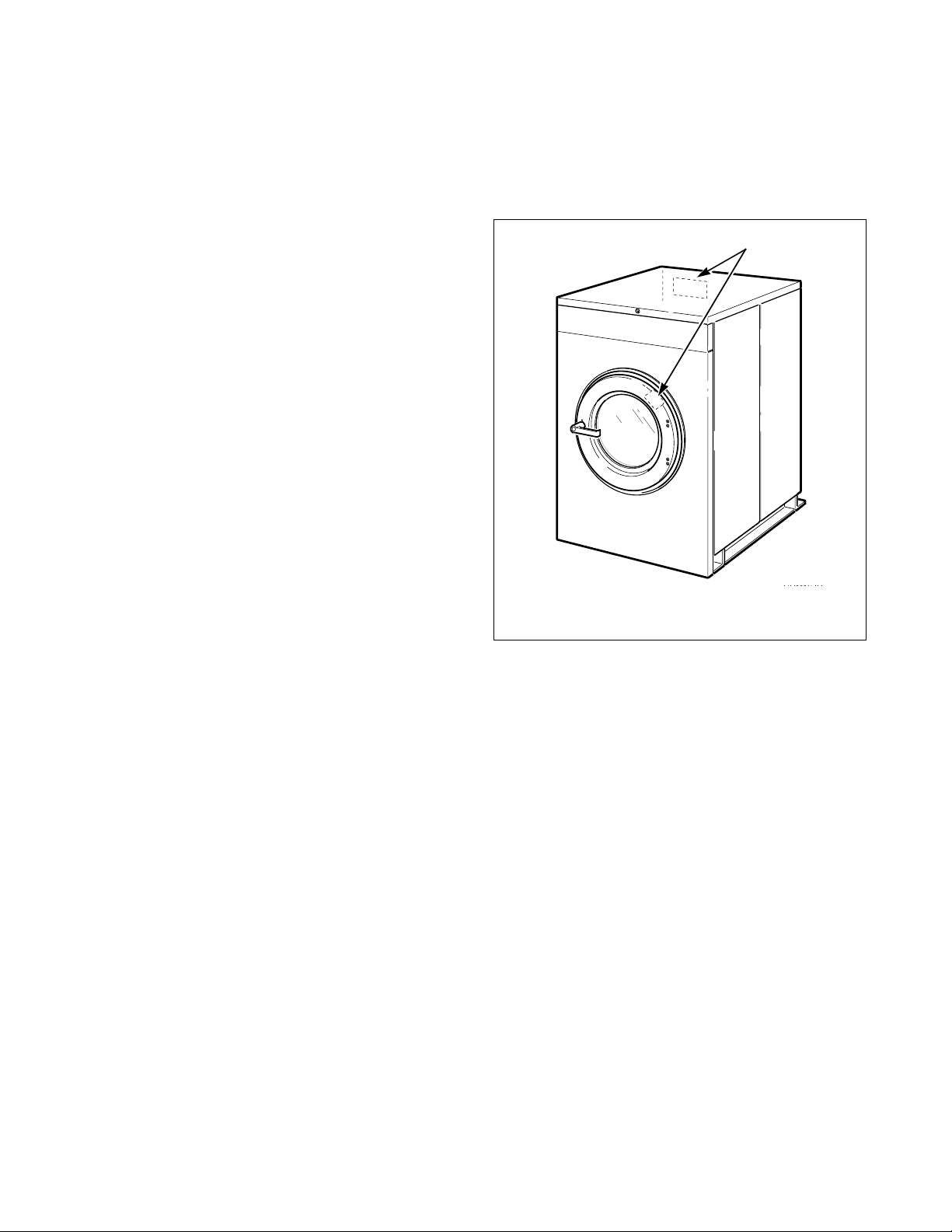
Nameplate Location
The nameplate is located at the rear of the machine and
inside door. Always provide the machine’s serial
number and model number when ordering parts or
when seeking technical assistance. Refer to Figure 1.
1
1 Nameplate
CHM167R
Figure 1
6
© Copyright, Alliance Laundry Systems LLC – DO NOT COPY or TRANSMIT
F232135
Page 9
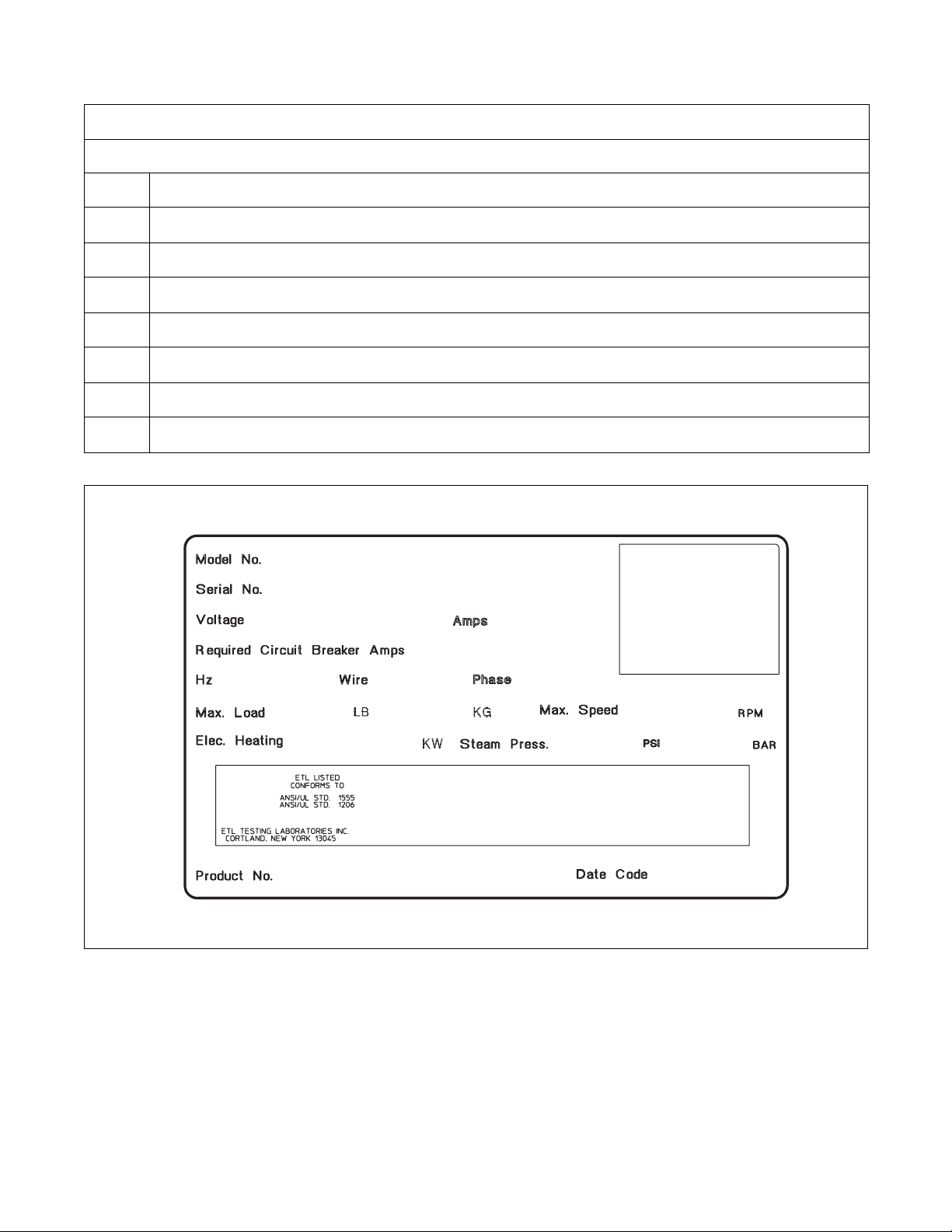
Model Number Familiarization Guide
Sample Model Number: *C40AC2OU60001
Introduction
*C
40
A
C
2
O
U6
0001
* Denotes Brand
Model Number Prefix
Washer-Extractor Capacity (pounds dry weight of laundry)
Type of Electrical Control
Actuation (C = Coin drop)
Washer-Extractor Speed Capability (2 = 2 speed)
Electrical Characteristics
Design Series
Option Identification (varies from machine to machine)
*C40AC2OU60001
00000000000
208 – 240
7
3
60 3 3
60
18
N/A N/A
500000
EXAMPLE OF NAMEPLATE
Figure 2
470
0
CHM2008N
CHM2008N
F232135
© Copyright, Alliance Laundry Systems LLC – DO NOT COPY or TRANSMIT
7
Page 10
Introduction
Replacement Parts
If literature or replacement parts are required, contact
the source from which the machine was purchased or
contact Alliance Laundry Systems at (920) 748-3950
for the name and address of the nearest authorized
parts distributor.
Customer Service
For technical assistance, call (920) 748-3121, Ripon,
Wisconsin U.S.A.
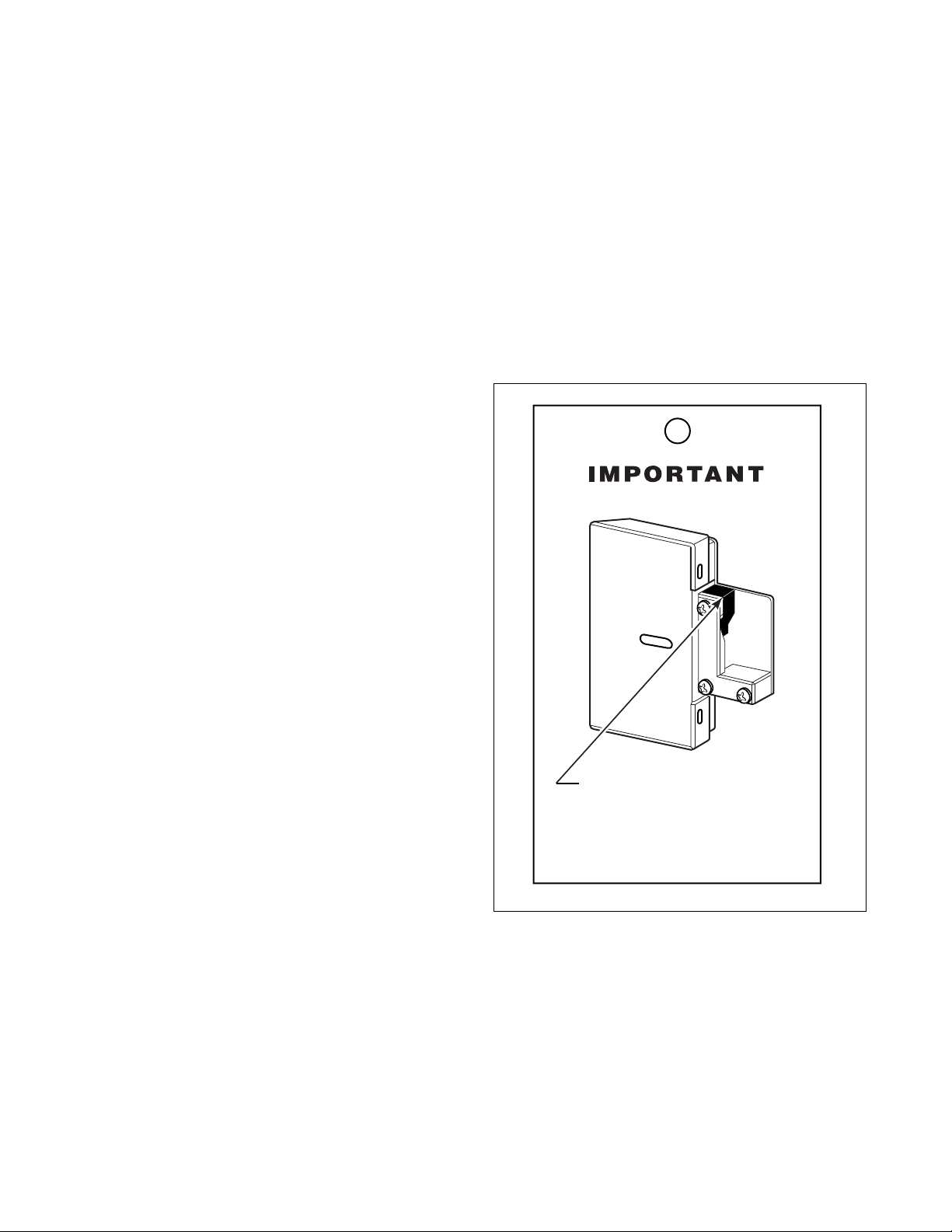
Remove After Shipment (OPL
Models Only)
A yellow retainer has been inserted in the door locks
of all cabinet hardmount on-premise laundry washerextractors to prevent the door from locking during
shipment. Remove the yellow retainer during
installation by pulling it off.
NOTE: Once retainer is removed, machine must be
powered to unlock door.
A tag has been attached to the washer-extractor’s door
handle as a reminder that the retainer must be removed
before operation. Refer to Figure 3.
Remove Yellow Retainer
Before Starting Machine.
Note: A Retainer has been
inserted to prevent the door from
locking during shipment.
CFS503N
Figure 3
8
© Copyright, Alliance Laundry Systems LLC – DO NOT COPY or TRANSMIT
F232135
Page 11

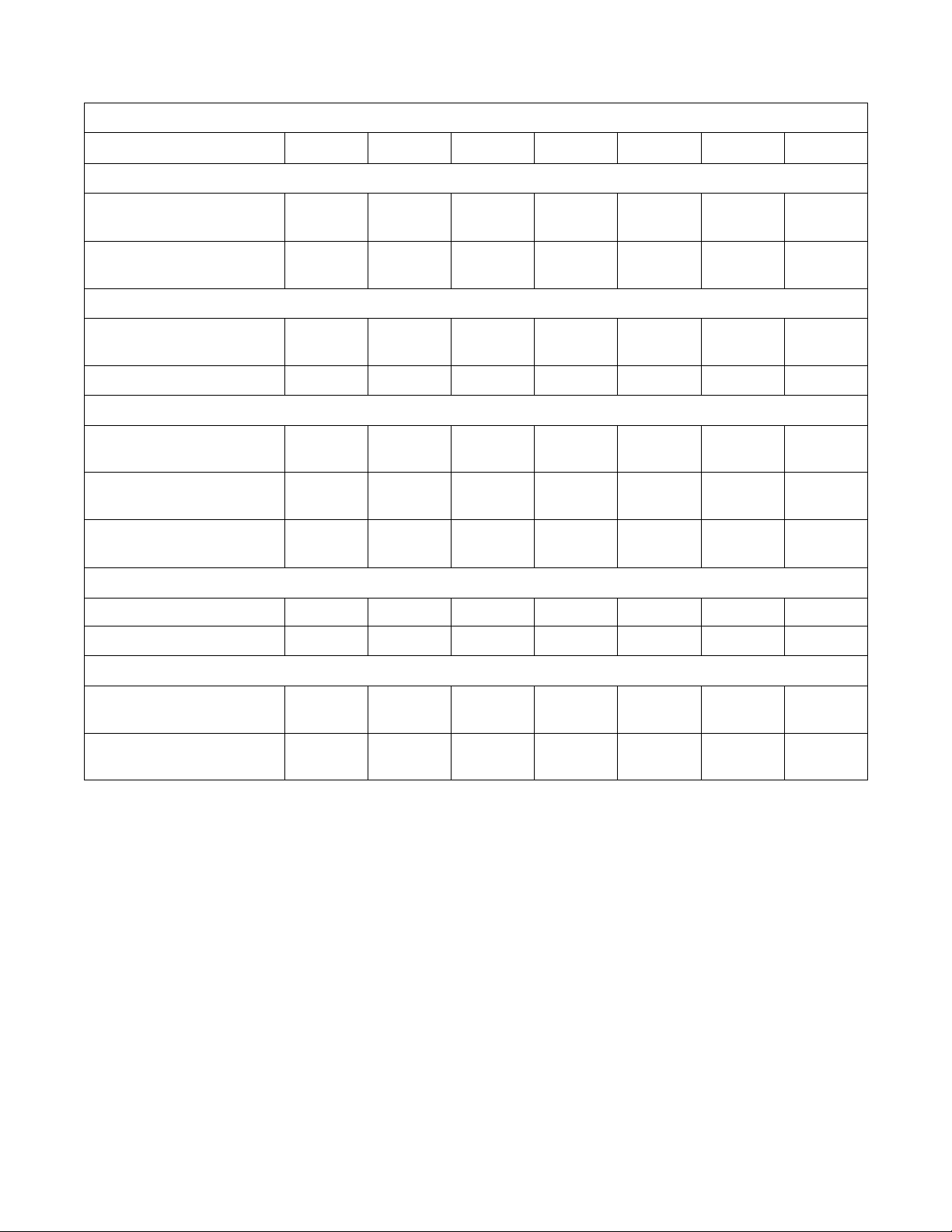
Specifications and Dimensions
2 Speed Models
Specification 18, 20 25 27, 30 35 40 50 60
Overall Dimensions
Overall width, in. (mm) 26
(660)
Overall height, in. (mm) 42-7/8
(1089)
Overall depth, in. (mm) 29-13/16
(757)
Weight and Shipping Information
Net weight, lbs. (kg) 390
(177)
Domestic shipping weight,
lbs. (kg)
Domestic shipping
volume, ft
Export shipping weight
lbs. (kg)
Export shipping volume,
3
(m3)
ft
Wash Cylinder Information
Cylinder diameter,
in. (mm)
3
(m3)
428
(194)
28
(0.8)
480
(218)
30.1
(0.86)
21
(533)
26
(660)
45
(1143)
33-7/8
(860)
435
(198)
470
(214)
33
(0.9)
530
(241)
36.7
(1.03)
21
(533)
29
(737)
45-7/8
(1165)
34-13/16
(884)
498
(226)
545
(245)
35
(1.0)
588
(267)
39.6
(1.11)
24
(610)
30-1/8
(765)
47-1/4
(1200)
38-1/2
(978)
650
(295)
680
(309)
39
(1.09)
760
(345)
47.1
(1.32)
26-1/4
(667)
30-5/8
(778)
47-7/8
(1216)
40-3/16
(1021)
706
(321)
744
(338)
42.6
(1.19)
846
(385)
54.1
(1.51)
26-1/4
(667)
34-1/16
(865)
50-13/16
(1291)
41-13/16
(1087)
820
(373)
875
(398)
53
(1.5)
1020
(464)
58.7
(1.67)
30
(762)
34-1/16
(865)
50-13/16
(1291)
42-13/16
(1087)
826
(375)
881
(400)
53
(1.5)
1027
(466)
58.7
(1.67)
30
(762)
Cylinder depth, in. (mm) 13-3/4
(349)
3
Cylinder volume, ft
Perforation size, in. (mm) 0.188
Perforation open area, % 17 17 23 17 17.5 18 18
F232135
(l) 2.76
(78.1)
(4.76)
© Copyright, Alliance Laundry Systems LLC – DO NOT COPY or TRANSMIT
18-3/4
(476)
3.76
(106.5)
0.188
(4.76)
16
(406)
4.19
(118.6)
0.188
(4.76)
18-3/8
(467)
5.76
(163.1)
0.188
(4.76)
20-1/4
(514)
6.34
(180)
0.188
(4.76)
20
(508)
8.18
(231.6)
0.188
(4.76)
22
(559)
9.00
(255)
0.188
(4.76)
9
Page 12
Specifications and Dimensions
Specification 18, 20 25 27, 30 35 40 50 60
Door Opening Information
Door opening diameter,
in. (mm)
Height of door bottom above
floor, in. (mm)
Power Consumption
12
(305)
14-3/8
(365)
2 Speed Models (Continued)
12
(305)
14-3/8
(365)
14-11/32
(364)
14
(356)
14-11/32
(364)
(406)
16
16-1/4
(413)
14-1/2
(368)
16-1/4
(413)
13-1/2
(343)
16-1/4
(413)
13-1/2
(343)
Average power used per cycle,
0.20 0.25 0.25 0.30 0.34 0.42 0.61
kW-hr
Average HVAC load, Btu/hr 425 400 400 510 510 700 700
Drive Train Information
Number of motors in drive
1111111
train
Wash/reverse power, HP (kW) 0.18
(0.13)
High extract power, HP (kW) 1.0
(0.746)
0.25
(0.19)
1.4
(1.04)
0.25
(0.19)
1.4
(1.04)
0.40
(0.30)
1.8
(1.3)
0.40
(0.30)
1.8
(1.3)
0.55
(0.41)
2.7
(2.01)
0.55
(0.41)
2.7
(2.01)
Cylinder Speeds
Wash/reverse speed, RPM53554747474444
High extract speed, RPM 525 540 480 470 470 450 450
Centrifugal Force Data
Wash/reverse centrifugal
0.85 0.90 0.75 0.82 0.82 0.825 0.825
force, Gs
High extract centrifugal force,
82.1 86.8 78.4 82.3 82.3 86.3 86.3
Gs
10
© Copyright, Alliance Laundry Systems LLC – DO NOT COPY or TRANSMIT
F232135
Page 13
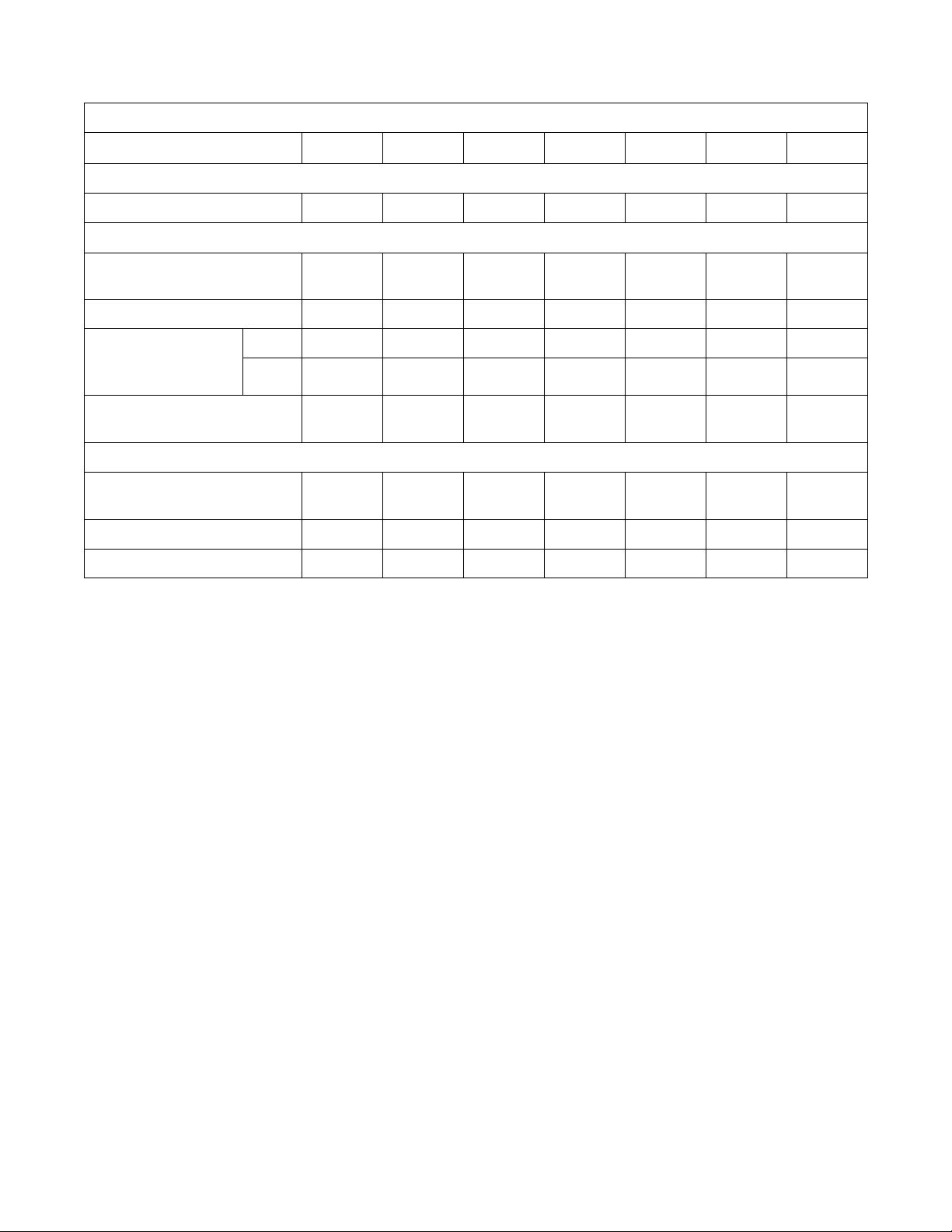
Specifications and Dimensions
2 Speed Models (Continued)
Specification 18/20 25 27, 30 35 40 50 60
Balance Detection
Vibration switch installed N/A N/A N/A N/A N/A N/A N/A
Direct Steam Heating (Optional)
Steam inlet connection size,
in. (mm)
1/2
(13)
1/2
(13)
1/2
(13)
1/2
(13)
1/2
(13)
1/2
(13)
1/2
(13)
Number of steam inlets 1111111
Steam required to raise
bath water temperature
°F (6°C)
10
Average steam use per cycle,
bhp (kg)
LOW 1.05 (0.75) 1.4 (1.01) 1.44 (1.03) 2.06 (1.48) 2.09 (1.51) 2.76 (1.99) 2.76 (1.99)
HIGH 1.4 (1.01) 1.59 (1.15) 1.91 (1.37) 2.69 (1.94) 2.84 (2.04) 3.59 (2.59) 3.59 (2.59)
0.71
(11.1)
0.87
(13.6)
0.97
(15.2)
1.4
(21.6)
1.43
(22.4)
1.84
(28.9)
1.84
(28.9)
Electrical Heating (Optional)
Total electrical heating capacity,
7.8 7.8 7.8 15.6 15.6 23.4 23.4
kW
Electrical heating elements 3336399
Electrical heat element size, kW 2.6 2.6 2.6 2.6 5.2 2.6 2.6
F232135
© Copyright, Alliance Laundry Systems LLC – DO NOT COPY or TRANSMIT
11
Page 14

Specifications and Dimensions
Gap Setting for Vibration Switch (VariableSpeed and Fixed-Speed Models)
18, 20 27, 30 35 40 50 60 80 125
Switch gap setting*,
in. (mm)
* Gap setting should be made with “GO-NO-GO” type feeler gauge. Lower value must not trip switch. Upper value must trip switch.
After the machine has been properly installed, the
vibration switch gap must be measured before
conducting the Control Function Test. Locate the gap
found between the vibration switch and the machine
structure. Refer to Figures 4, 5, 6, 7 and 8. To check
the gap setting of the switch, proceed as follows:
1. Remove the front panel on 18-50 models.
Remove the rear panel on 60-80 models. Remove
the top cover on the 125 model. The switch can
be seen inside the bottom right corner of the Aframe, mounted on a bracket. Refer to Figures 4,
5, 6, 7 and 8.
0.015-0.025
(0.38-0.64)
0.025-0.035
(0.64-0.89)
0.030-0.040
(0.76-1.02)
0.020-0.030
(0.51-0.64)
Table 1
0.025-0.035
(0.64-0.89)
0.013-0.015
(0.20-0.25)
0.009-0.011
(0.23-0.28)
0.006-0.008
(0.15-0.20)
2. Measure the gap distance when the switch is in
both the open and closed positions. The
specifications should be at the minimum switch
gap setting when the switch is open and at the
maximum switch gap setting when the switch is
closed. If these distances are not correct, adjust
the balance switch to these specifications.
NOTE: The standard position of the switch is open,
or non-tripped.
3. Tighten nuts on switch extension after adjusting
the gap. Measure the gap distance to verify
accurate setting.
12
© Copyright, Alliance Laundry Systems LLC – DO NOT COPY or TRANSMIT
F232135
Page 15
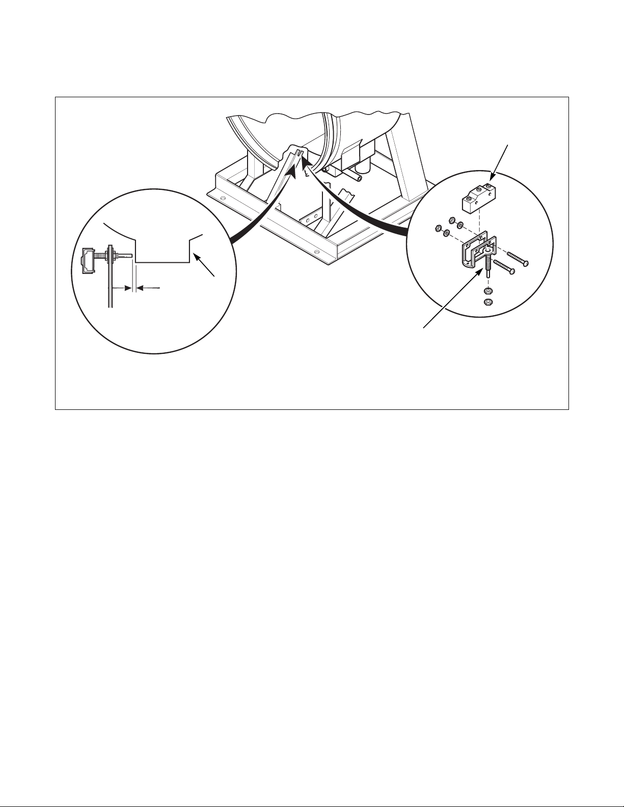
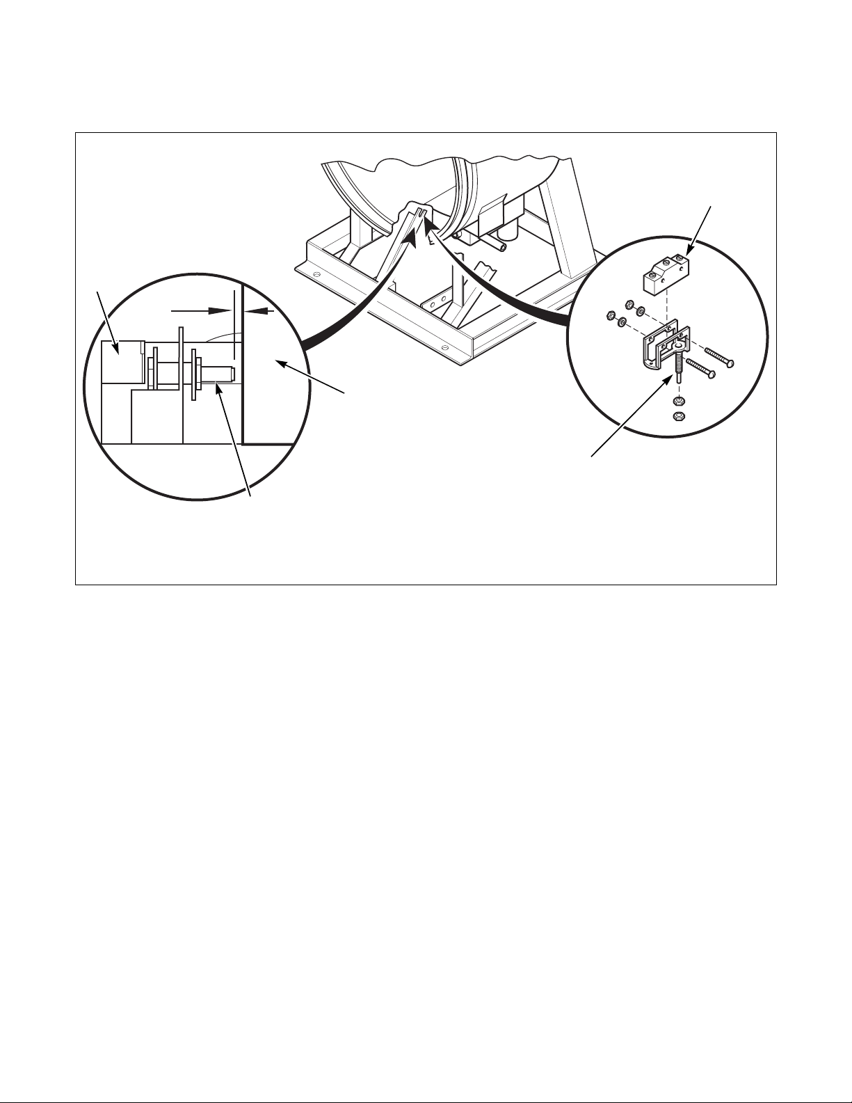
For 18, 20, 25, 27, 30 and 35 Pound
Capacity Machines
Specifications and Dimensions
3
2
1 Sump 3 Vibration Switch
2 Gap Distance 4 Switch Extension
1
4
Figure 4
CHM1995N
CHM1995N
F232135
© Copyright, Alliance Laundry Systems LLC – DO NOT COPY or TRANSMIT
13
Page 16
Specifications and Dimensions
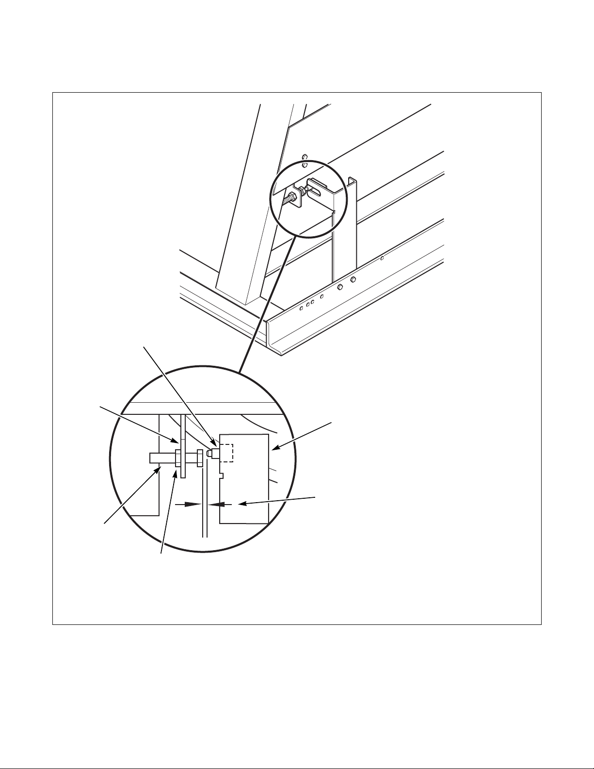
For 40 and 50 Pound Capacity Variable-Speed
and Fixed-Speed Machines
3
2
1
3
4
4
1 Sump 3 Vibration Switch
2 Gap Distance 4 Switch Extension
Figure 5
CHM2000N
14
© Copyright, Alliance Laundry Systems LLC – DO NOT COPY or TRANSMIT
F232135
Page 17
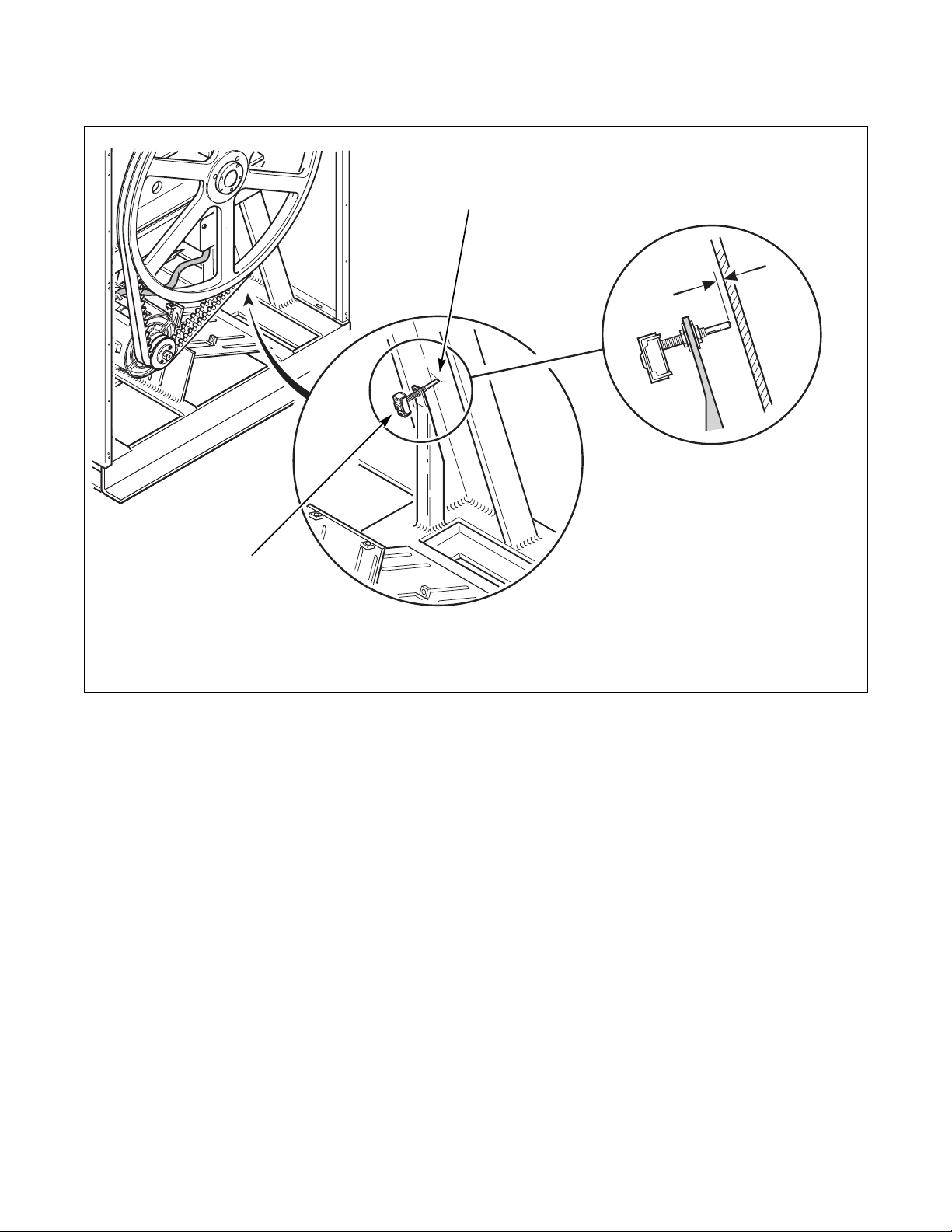
For 60 Pound Capacity Variable-Speed and
Fixed-Speed Machines
Specifications and Dimensions
2
3
2
1
6
4
5
1 Lower Bracket 4 Balance Bolt
2 Upper Bracket 5 Lock Nut
3 Vibration Switch 6 Gap Distance
CHM1999N
CHM1999N
F232135
Figure 6
© Copyright, Alliance Laundry Systems LLC – DO NOT COPY or TRANSMIT
15
Page 18
Specifications and Dimensions
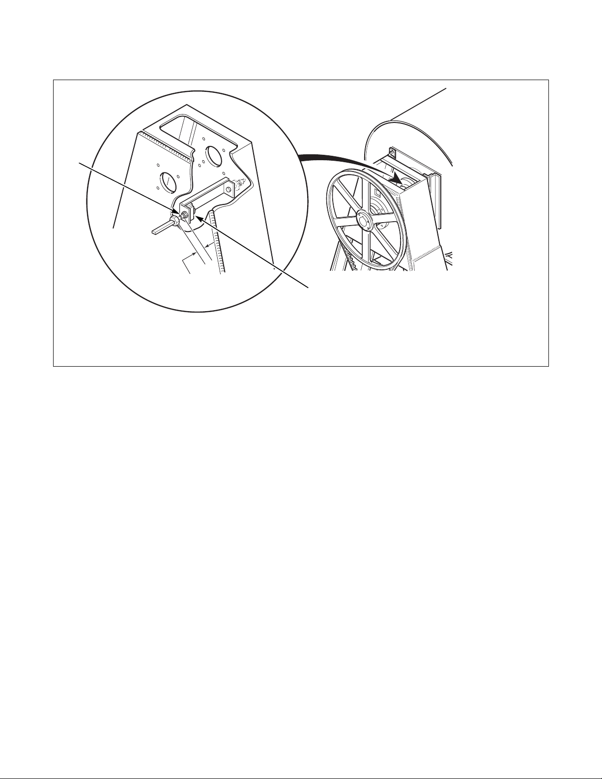
For 80 Pound Capacity Machines
1
2
3
1 Switch Extension 3 Vibration Switch
2 Gap Distance
Figure 7
CAB1998N
CHM1998N
16
© Copyright, Alliance Laundry Systems LLC – DO NOT COPY or TRANSMIT
F232135
Page 19
For 125 Pound Capacity Machines
3
2
1
1 Vibration Switch 3 Switch Extension
2 Gap Distance
Specifications and Dimensions
CHM1993N
Figure 8
F232135
© Copyright, Alliance Laundry Systems LLC – DO NOT COPY or TRANSMIT
17
Page 20
Specifications and Dimensions
Variable-Speed and Fixed-Speed Models
Specification 20 30 35 40 50 60 80 125
Overall Dimensions
Overall width, in. (mm) 26
(660)
Overall height, in. (mm) 42-7/8
(1089)
Overall depth, in. (mm) 29-13/16
(757)
Weight and Shipping Information
Net weight, lbs. (kg) 386
(175)
Domestic shipping weight, lbs. (kg) 424
(191)
3
Domestic shipping volume, ft
Export shipping weight, lbs. (kg) 476
Export shipping volume, ft
(m3)28
(0.8)
(215)
3
(m3)30.1
(0.86)
29
(737)
45-7/8
(1165)
34-13/16
(884)
498
(226)
545
(245)
35
(1.0)
588
(267)
39.6
(1.11)
30-1/8
(765)
47-1/4
(1200)
38-1/2
(978)
621
(282)
670
(301)
39
(1.09)
731
(332)
47.1
(1.32)
30-5/8
(778)
47-7/8
(1216)
40-3/16
(1021)
706
(321)
744
(338)
42.6
(1.19)
846
(385)
54.1
(1.51)
34-1/16
(865)
50-13/16
(1291)
42-13/16
(1087)
767
(348)
818
(371)
53
(1.5)
967
(439)
58.7
(1.67)
34-1/16
(865)
41-1/2
(1054)48(1219)
50-13/16
(1291)56(1422)
42-13/16
(1087)
773
(350)
824
(373)
53
(1.5)
1020
(463)
58.7
(1.67)
51-5/8
(1311)
1406
(633)
1456
(655)
97
(2.7)
1506
(678)
109.5
(3.1)
70-1/2
(1791)
56-3/4
(1441)
2346
(1066)
2421
(1098)
153
(4.3)
2701
(1225)
173
(4.8)
Wash Cylinder Information
Cylinder diameter, in. (mm) 21
(533)
Cylinder depth, in. (mm) 13-3/4
(349)
3
Cylinder volume, ft
(l) 2.76
(78.1)
Perforation size, in. (mm) 0.188
(4.76)
24
(610)
16
(406)
4.19
(118)
0.188
(4.76)
26-1/4
(667)
18-3/8
(467)
5.76
(163.1)
0.188
(4.76)
26-1/4
(667)
20-1/4
(514)
6.34
(180)
0.188
(4.76)
30
(762)
20
(508)
8.18
(232)
0.188
(4.76)
30
(762)
22
(559)
9.00
(255)
0.188
(4.76)
36
(914)42(1060)
22
(559)
12.96
(367)
0.188
(4.76)
24
(609)
19.24
(545)
0.188
(4.76)
Perforation open area, % 17231717.518182717
Door Opening Information
Door opening size, in. (mm) 12
(305)
Height of door bottom above floor, in. (mm) 14-3/8
(365)
14-11/32
(364)
14
(356)
14-11/32
(364)
16
(406)
16-1/4
(413)
14-1/2
(368)
16-1/4
(413)
13-1/2
(343)
16-1/4
(413)
13-1/2
(343)
18-1/2
(470)
17-3/4
(451)
20
(508)
29
(737)
Power Consumption
Average power used per cycle, kW-hr 0.05 0.07 0.20 0.34 0.37 0.21 0.40 0.60
Average HVAC load, Btu/hr 400 450 510 510 750 750 950 1200
18
© Copyright, Alliance Laundry Systems LLC – DO NOT COPY or TRANSMIT
F232135
Page 21
Specifications and Dimensions
Variable-Speed and Fixed-Speed Models (Continued)
Specification 20 30 35 40 50 60 80 125
Drive Train Information
Number of motors in drive train 11111111
Drive motor power, HP (kW) 2
(1.5)
Cylinder Speeds
Gentle wash/reverse speed, RPM 2927262624242227
Wash/reverse speed, RPM 5248464743434037
Distribution speed, RPM 8286737368776362
Low extract speed, RPM 366 343 328 328 307 307 280 260
Medium extract speed, RPM
534 500 478 478 447 447 408 380
(Not available on Electronic Control models.)
High extract speed, RPM 685 641 613 614 573 574 524 485
Centrifugal Force Data
Gentle wash centrifugal force, Gs 0.25 0.25 0.25 0.25 0.25 0.25 0.25 0.43
Wash/reverse centrifugal force, Gs 0.8 0.8 0.8 0.8 0.8 0.8 0.8 0.8
Distribution centrifugal force, Gs 22222222
Low extract centrifugal force, Gs 40 40 40 40 40 40 40 40
Medium extract centrifugal force, Gs 85 85 85 85 85 85 85 85
High extract centrifugal force, Gs 140 140 140 140 140 140 140 140
2
(1.5)
2
(1.5)
2
(1.5)
2
(1.5)
3
(2.2)
5
(3.7)
7.5
(5.6)
Balance Detection
Vibration switch installed* Standard Standard Standard Standard Standard Standard Standard Standard
Direct Steam Heating (Optional)
Steam inlet connection size,
in. (mm)
1/2
(13)
1/2
(13)
1/2
(13)
1/2
(13)
1/2
(13)
1/2
(13)
1/2
(13)
3/4
(19)
Number of steam inlets 11111111
Steam required to raise bath water
temperature 10°F (6°C), lbs. (kg)
Average steam use per cycle, bhp (kg) 0.54
LOW 0.62
(0.28)
HIGH 0.88
(0.4)
(8.3)
0.92
(0.42)
1.31
(0.6)
0.73
(11.3)
2.1
(1.51)
2.69
(1.96)
1.4
(21.6)
2.09
(1.51)
2.84
(2.04)
1.43
(22.4)
2.8
(2.0)
3.6
(2.59)
1.8
(28.9)
3.6
(1.63)
5.5
(2.49)
2.32
(36.4)
4.1
(2.93)
6.0
(4.34)
2.93
(45.9)
6.8
(4.9)
8.9
(6.4)
4.5
(71)
Electrical Heating (Optional)
Total electrical heating capacity, kW 7.8 7.8 15.6
15.6
23.4 23.4 31.2 N/A
Electrical heating elements 33639912N/A
Electrical heat element size, kW 2.6 2.6 2.6 5.2 2.6 2.6 2.6 N/A
* Refer to Gap Setting for Vibration Switch (Variable-Speed and
Fixed-Speed Models) section for specifications.
F232135
© Copyright, Alliance Laundry Systems LLC – DO NOT COPY or TRANSMIT
19
Page 22
Specifications and Dimensions
4
3
1
2
I
5
6
J
7
8
S
R
H
L
A
B
C
G
N
D
E
F
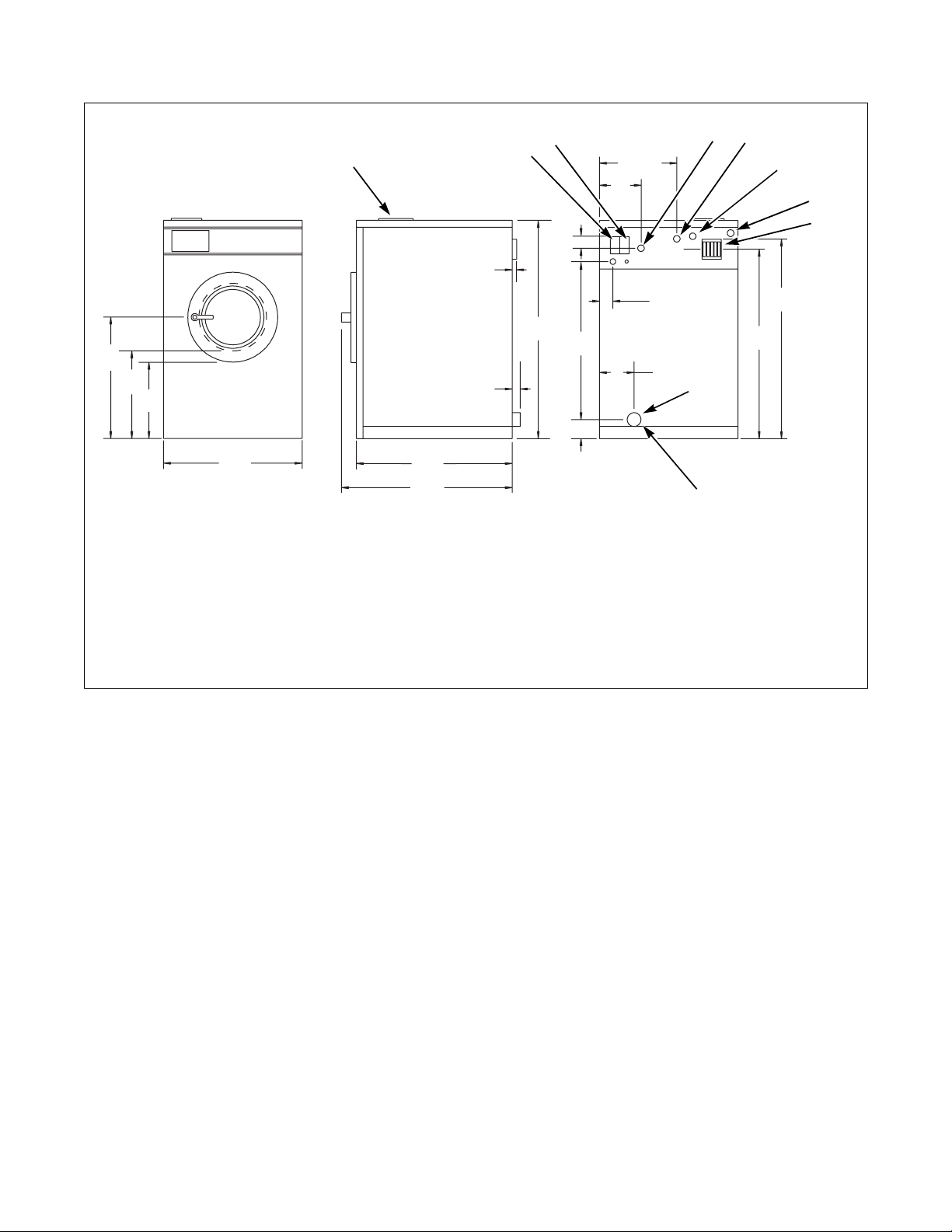
18, 20, 25, 27, 30, 35, 40, 50, 60 AND 80 POUND CAPACITY MACHINES
1 Supply Dispenser 5 Hot Water Inlet
2 Input Power Block 6 Extra Inlet Valve
3 External Chemical Supply Signal Terminal Strip
(OPL only)
7 External Chemical Supply Inlet (OPL only)
8 Vacuum Breaker
4 Cold Water Inlet 9 Drain Outlet
Figure 9
K
Q
P
M
O
9
CHM2019N
CHM2019N
20
© Copyright, Alliance Laundry Systems LLC – DO NOT COPY or TRANSMIT
F232135
Page 23

Specifications and Dimensions
Machine Capacity Dimensions
Dimensions 18, 20 25 27, 30 35 40 50 60 80
A
B
C
D
E
G
H
K
M
N
O
P
Q
R
S
22-15/16
in.
(583 mm)
in.
17-1/4
(438 mm)
in.
14-3/8
(365 mm)
in.
26
(660 mm)
in.
25-5/8
(650 mm)
F
29-13/16
(757 mm)
in.
0001-1/8
in.
42
(1062 mm)
in.
I
J
12-1/2
(318 mm)
in.
11-1/2
(292 mm)
in.
3-1/2
(89 mm)
in.
L
34-1/2
(876 mm)
in.
5-3/4
(146 mm)
in.
4-1/2
(114 mm)
in.
2
(51 mm)
36-3/16
in.
(919 mm)
38-1/2 in.
(978 m)
1-3/16 in.
(30 mm)
3 in.
(76 mm)
23 in.
(584 mm)
17-1/4 in.
(438 mm)
14-3/8 in.
(365 mm)
26 in.
(660 mm)
30 in.
(762 mm)
34-3/16 in.
(868 mm)
45 in.
(1143 mm)
12-1/2
in.
(318 mm)
11-1/2 in.
(292 mm)
3-1/2 in.
(89 mm)
37-1/2 in.
(952 mm)
5-3/4 in.
(146 mm)
4-1/2 in.
(114 mm)
2 in.
(51 mm)
39-3/16 in.
(995 mm)
41-1/2 in.
(1054 mm)
1-3/16 in.
(30 mm)
3 in.
(76 mm)
24 in.
(610 mm)
17 in.
(432 mm)
14 in.
(356 mm)
29 in.
(737 mm)
30-5/8 in.
(775 mm)
34-13/16 in.
(884 mm)
45 in.
(1143 mm)
15-1/4
in.
(387 mm)
14-3/4 in.
(375 mm)
3-3/4 in.
(95 mm)
37-11/16
in.
(957 mm)
5-7/8 in.
(149 mm)
4 in.
(102 mm)
2 in.
(51 mm)
38-15/16
in.
(989 mm)
41 in.
(1041 mm)
1-3/16 in.
(30 mm)
3 in.
(76 mm)
26 in.
(660 mm)
19 in.
(483 mm)
16 in.
(406 mm)
30-1/8 in.
(765 mm)
34 in.
(864 mm)
38-1/8 in.
(968 mm)
in.
(29 mm)
47 in.
(1194 mm)
14-1/4 in.
(362 mm)
10-13/16
in.
(275 mm)
2-3/4
in.
(70 mm)
40-1/8
in.
(1020 mm)
7-5/16 in.
(186 mm)
4-3/4 in.
(121 mm)
2
in.
(51 mm)
41-15/16
in.
(1064 mm)
41-15/16 in.
(1064 mm)
1-3/16 in.
(30 mm)
3 in.
(76 mm)
25-3/4 in.
(654 mm)
18 in.
(457 mm)
14-1/2 in.
(368 mm)
30-5/8 in.
(778 mm)
36 in.
(914 mm)
40-3/16 in.
(1021 mm)
1/2 in.
(13 mm)
47 in.
(1194 mm)
15-7/16 in.
(392 mm)
14-7/16 in.
(367 mm)
3-13/16 in.
(97 mm)
39 in.
(990 mm)
5-1/2 in.
(140 mm)
4-3/4 in.
(121 mm)
3 in.
(76 mm)
42-1/8 in.
(1070 mm)
43-3/16 in.
(1097 mm)
1-3/16 in.
(30 mm)
3 in.
(76 mm)
26-3/8 in.
(670 mm)
18-1/4 in.
(464 mm)
13-1/2 in.
(343 mm)
34-1/16 in.
(865 mm)
37-3/4
in.
(959 mm)
41-13/16
in.
(1062 mm)
1/2 in.
(13 mm)
49-15/16 in.
(1268 mm)
20-3/4 in.
(527 mm)
19-3/4
in.
(502 mm)
3-1/2 in.
(89 mm)
41-1/2 in.
(1054 mm)
6-7/16 in.
(163 mm)
5 in.
(127 mm)
3
in.
(76 mm)
43-3/16 in.
(1097 mm)
45-1/2 in.
(1156 mm)
1-3/16 in.
(30 mm)
3 in.
(76 mm)
26-3/8 in.
(670 mm)
18-1/4
in.
(464 mm)
13-1/2 in.
(343 mm)
34-1/16 in.
(865 mm)
38-3/4 in.
(984 mm)
42-13/16 in.
(1087 mm)
1/2 in.
(13 mm)
49-15/16 in.
(1268 mm)
20-3/4 in.
(527 mm)
19-3/4 in.
(502 mm)
3-1/2 in.
(89 mm)
41-1/2 in.
(1054 mm)
6-7/16 in.
(163 mm)
5
in.
(127 mm)
3 in.
(76 mm)
43-3/8 in.
(1102 mm)
45-1/2 in.
(1156) mm)
1-3/16 in.
(30 mm)
3 in.
(76 mm)
30-5/8 in.
(777 mm)
21-5/8
(549 mm)
17-3/4 in.
(451 mm)
41-1/2 in.
(1054 mm)
48 in.
(1219 mm)
51
(1295 mm)
1/2 in.
(13 mm)
56 in.
(1422 mm)
22-1/4 in.
(572 mm)
14-7/16 in.
(378 mm)
3-7/16 in.
(87 mm)
44-1/2 in.
(1130 mm)
6-3/8 in.
(162 mm)
5-3/4
(146 mm)
3 in.
(76 mm)
42-3/4 in.
(1086 mm)
50 in.
(1270 mm)
1-3/16 in.
(30 mm)
3 in.
(76 mm)
in.
in.
in.
F232135
© Copyright, Alliance Laundry Systems LLC – DO NOT COPY or TRANSMIT
21
Page 24
Specifications and Dimensions
1
2
J
K
L
M
N
O
I
3
4
5
6
R
S
A
B
C
D
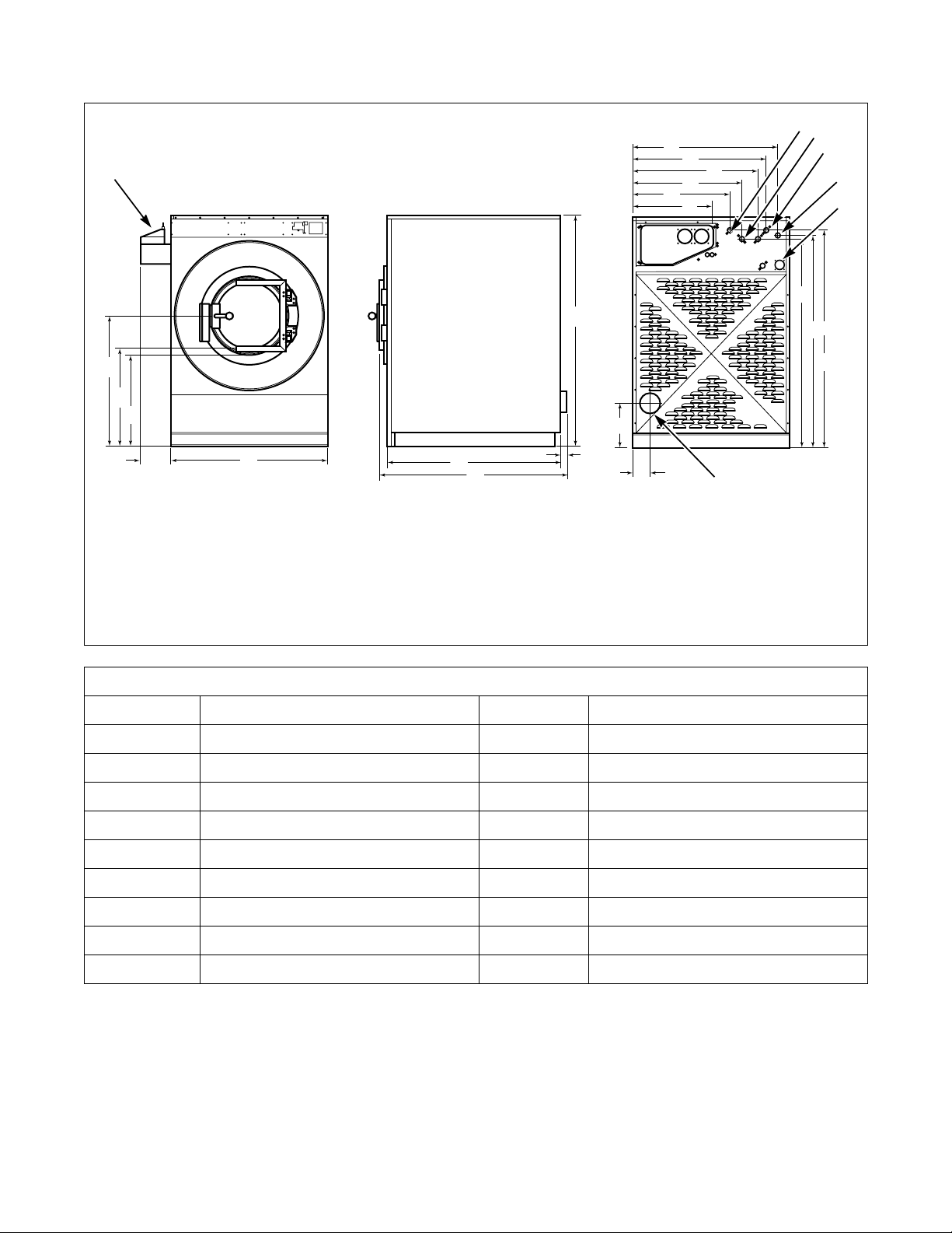
1 Dry Chemical Dispenser
(Optional – OPL Models Only)
2 Cold Water Inlet 6 Steam Inlet (Optional)
3 Extra Water Inlet (Optional) 7 Drain Outlet
E
125 POUND CAPACITY MACHINES
F
G
4 Hot Water Inlet
5 Liquid Chemical Inlet
P
H
Machine Capacity Dimensions for 125 Pound Models
in. (1016 mm)
A
B
C
D
40
in. (768 mm)
30-1/4
in. (737 mm)
29
8
in. (203 mm)
K
L
M
N
Q
7
B023I
41 in. (1041 mm)
38-1/2 in. (978 mm)
33-1/2 in. (851 mm)
29-3/4 in. (756 mm)
T
B023I
22
48
E
F
G
H
I
J
in. (1219 mm)
50-1/2
in. (1283 mm)
in. (1422 mm)
56-3/4
1
in. (25 mm)
70-1/2
in. (1791 mm)
44-1/2
in. (1130 mm)
© Copyright, Alliance Laundry Systems LLC – DO NOT COPY or TRANSMIT
O
P
Q
R
S
T
24 in. (610 mm)
13 in. (330 mm)
4-7/8 in. (124 mm)
63-7/8 in. (1622 mm)
64-7/8 in. (1648 mm)
66-5/8 in. (1692 mm)
F232135
Page 25
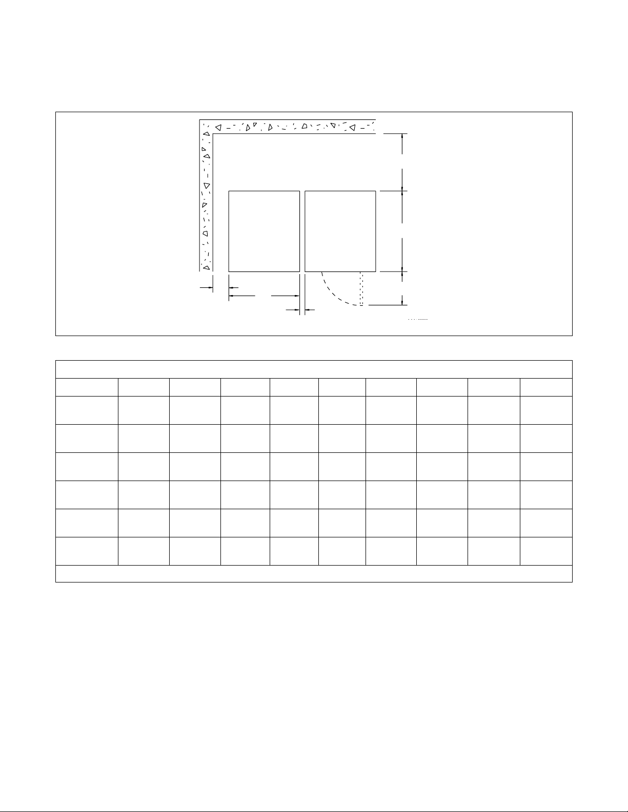
Dimensional Clearances
Installation
F
E
FRONT
A
Machine Capacity Dimensional Clearances
Dimensions 18, 20 25 27, 30 35 40 50 60 80 125
A
B
C
D
E
F
*For 80 pound models intended for standard mounting, clearance should be 6 in. (150 mm).
2 in.
(50 mm)
26 in.
(660 mm)
1 in.
(25 mm)
16-3/8 in.
(416 mm)
25-5/8 in.
(650 mm)
12 in.
(305 mm)
2 in.
(50 mm)
26 in.
(660 mm)
1 in.
(25 mm)
16-3/8 in.
(416 mm)
29-7/16 in.
(705 mm)
12 in.
(305 mm)
(50 mm)
(737 mm)
(25 mm)
19-1/4 in.
(490 mm)
30-1/2 in.
(775 mm)
(305 mm)
2 in.
29 in.
1 in.
12 in.
B
C
30-1/8 in.
(765 mm)
19-1/4 in.
(490 mm)
(864 mm)
(457 mm)
2 in.
(50 mm)
1 in.
(25 mm)
34 in.
18 in.
2 in.
(51 mm)
30-5/8 in.
(778 mm)
1 in.
(25 mm)
22 in.
(560 mm)
36 in.
(914 mm)
12 in.
(305 mm)
D
2 in.
(50 mm)
34-1/16 in.
(865 mm)
1 in.
(25 mm)
22 in.
(560 mm)
37-1/2 in.
(953 mm)
12 in.
(305 mm)
2 in.
(50 mm)
34-1/16 in.
(865 mm)
1 in.
(25 mm)
22 in.
(560 mm)
38-3/4 in.
(984 mm)
12 in.
(305 mm)
2 in.
(50 mm)
41-1/2 in.
(1054 mm)
1 in.*
(25 mm)
25 in.
(635 mm)
51-5/8 in.
(1311 mm)
24 in.
(610 mm)
24 in.
(600 mm)
48 in.
(1219 mm)
12 in.
(300 mm)
26-1/4 in.
(667 mm)
56-3/4 in.
(1441 mm)
24 in.
(610 mm)
U158M
F232135
© Copyright, Alliance Laundry Systems LLC – DO NOT COPY or TRANSMIT
23
Page 26

Installation
Machine Foundation
NOTE: Do not mount on wooden floors, above
ground level, or over basements or crawl spaces
because of the high extract speed and the G-forces
exerted.
The floor must be 3500 psi minimum reinforced
concrete set firmly in clean, compacted fill dirt.
Machine Foundation Requirements
Models
2 Speed and Fixed-Speed
(20-60 Models)
Variable-Speed
(20-60 Models)
Va ri ab le Speed
80 Models 9 in.
125 Models 12 in.
Foundation
Thickness
4
in.
(102 mm)
6 in.
(152 mm)
(229 mm)
(304 mm)
Floor
Thickness
4 in.
(102 mm)
6 in.
(152 mm)
6 in.
(152 mm)
6 in.
(152 mm)
The machine must be anchored to a smooth, level
surface so that the entire base of the machine is
supported and rests on the mounting surface. (Do not
support the machine on only four points.)
An elevated foundation must not exceed 8 inches
(203 mm).
Refer to Table 2 for foundation and anchoring
requirements.
Anchoring
Installation
Foundation
Method(s)
Direct-to-finished-floor,
elevated base frame, or
concrete foundation
Direct-to-finished-floor
or concrete foundation
Direct-to-finished-floor
or concrete foundation
Anchoring
Method(s)
Requirement
Expansion bolt
or J-bolt
J-bolt or
mounting bolt
J-bolt, mounting
bolt, or rebar
frame
Bolt
Diameter
Size
(minimum)
5/8 in.
5/8 in.
3/4 in.
Table 2
24
© Copyright, Alliance Laundry Systems LLC – DO NOT COPY or TRANSMIT
F232135
Page 27
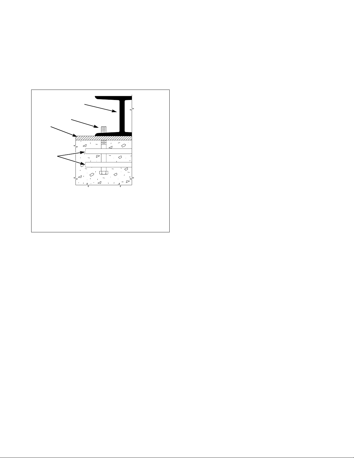
NOTE: For 80 and 125 pound models, a
bolt-locator fixture or rebar frame is available as
an option. This is designed to be embedded in
concrete. Refer to Figure 10.
IMPORTANT: Do not install any variable-speed
machine on an elevated base frame.
1
2
3
4
Installation
1 Machine Base
2 Mounting Bolt Threads
3 Grouting
4 Bolt-Locator Fixture or Rebar Frame
Figure 10
P035I
F232135
© Copyright, Alliance Laundry Systems LLC – DO NOT COPY or TRANSMIT
25
Page 28

Installation
Refer to Table 3 and Table 4 for static and dynamic
loads on the floor or foundation.
Floor Load Data, 2 Speed Models
Specification 18, 20 25 27, 30 35 40 50 60
Static floor load,
lbs. (kN)
Static pressure,
2
(kN-m2)
lbs-ft
Dynamic load,
lbs. (kN)
Dynamic pressure,
2
(kN-m2)
lbs-ft
Dynamic load
frequency, Hz
Maximum moment
about machine base,
lbs-ft (kN-m)
476
(2.12)
104
(4.96)
296
(1.31)
64.4
(3.08)
549
(2.44)
103
(4.94)
420
(1.87)
79.3
(3.80)
653
(2.90)
106.3
(5.10)
427
(1.90)
69
(3.33)
804
(3.58)
113
(5.41)
581
(2.58)
82
(3.91)
873
(3.88)
123
(5.89)
987
(4.4)
139
(6.7)
1041
(4.63)
117
(5.62)
860
(3.83)
97
(4.64)
8.75 9.00 8.00 7.83 7.80 7.50 7.50
565
(0.769)
832
(1.0)
847
(1.16)
1247
(1.6)
2118
(2.9)
1894
(2.4)
Tabl e 3
1015
(4.53)
115
(5.5)
1418
(6.3)
161
(7.6)
2470
(3.35)
Floor Load Data, Variable-Speed Models
Specification 20303540506080125
Static floor load, lbs. (kN) 513
(2.27)
Static pressure, lbs-ft
2
(kN-m2)112
(5.35)
Dynamic load, lbs. (kN) 512
(2.27)
Dynamic pressure, l
2
(kN-m2)
bs-ft
112
(5.35)
688
(3.01)
112
(5.35)
7.55
(3.36)
123
(5.88)
934
(4.1)
132
(6.3)
979
(4.35)
138
(6.60)
873
(3.88)
123
(5.89)
1123
(5)
158
(7.6)
1136
(5.0)
128
(6.1)
1397
(6.25)
159
(7.5)
914
(4.07)
103
(4.95)
1428
(6.3)
161
(7.6)
1972
(8.8)
144
(6.9)
2243
(9.98)
164
(7.84)
2316
(10.3)
145
(6.93)
3500
(15.5)
364
(17.4)
Dynamic load frequency, Hz 11.5 10.7 10.22 10.2 9.58 9.58 8.73 8.08
Maximum moment about
machine base, lbs-ft (kN-m)
979
(1.33)
1510
(2.05)
2122
(2.7)
2410
(3.3)
3071
(3.9)
3138
(4.25)
5749
(7.2)
11,667
(14.7)
Table 4
26
© Copyright, Alliance Laundry Systems LLC – DO NOT COPY or TRANSMIT
F232135
Page 29
Machine Anchoring
2
Before anchoring the machine, refer to Ta ble 2 to
determine the appropriate method of anchoring for the
machine.
NOTE: Improper installation may void the
warranty. Consult the manufacturer or distributor
before varying from a procedure.
Installation
Direct-to-Finished-Floor Installation
Installing With Expansion Bolts
(2 Speed Models, Fixed-Speed and
A-Control Variable-Speed Models)
NOTE: Expansion bolts are not suitable VNV
machine installations.
1. Verify the floor meets the requirements given in
the Machine Foundation section.
2. Mounting surface should be level and machine
must be properly grouted.
NOTE: If replacing a 35 pound machine with a
40 pound machine, note differences in cabinet size.
Refer to pages 20, 21 and 32.
NOTE: If replacing a 50 pound machine with a
60 pound machine, note differences in cabinet size.
Refer to pages 20, 21 and 32.
3. Use the base of the machine as a template by
positioning the machine in the desired location
and marking the pre-drilled mounting holes on
the floor. Metal templates are available at cost
through Alliance Laundry Systems. Refer to
Table 5 for ordering information.
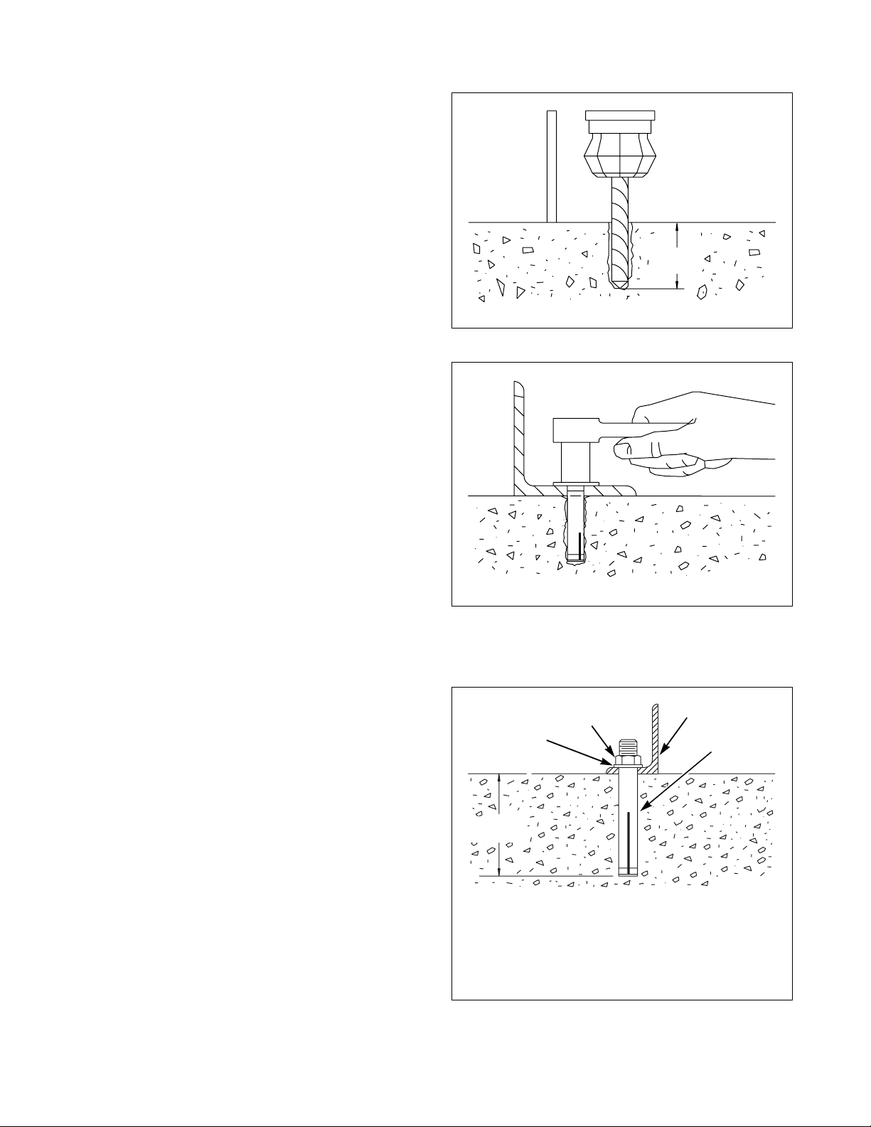
4. Set the drill depth gauge to 2-9/16 inches
(65 mm).
2-9/16 in.
(65 mm)
U137I
U137I
Figure 11
H029I
H029I
Figure 12
The completed expansion bolt installation is shown in
Figure 13.
2
1
3
4
5. Drill the holes to the set depth. Refer to Figure
11.
6. Use compressed air or a squeeze bulb to clean out
each hole.
7. Install the machine anchors, using the included
tool.
8. Secure the machine to the floor, using the bolts
furnished with the anchors. Tighten the locknuts
by even increments – one after the other – until
all are tightened evenly and the machine is
fastened securely to the floor. Refer to Figure 12.
F232135
© Copyright, Alliance Laundry Systems LLC – DO NOT COPY or TRANSMIT
2-9/16 in.
(65 mm)
CHM203
CHM2032N
1 Washer
2 Locknut
3 Machine Base
4 5/8 in. (19 mm) Diameter Expansion Bolt
Figure 13
27
Page 30
Installation
Installing With J-Bolts
1. Verify the floor meets the requirements given in
the Machine Foundation section.
2. Install J-bolts in concrete as shown in the
mounting bolt layouts (Figure 18 and Figure 19)
following these instructions.
NOTE: If replacing a 35 pound machine with a
40 pound machine, note differences in cabinet size.
Refer to pages 20, 21 and 32.
NOTE: If replacing a 50 pound machine with a
60 pound machine, note differences in cabinet size.
Refer to pages 20, 21 and 32.
NOTE: There are two different mounting bolt
layouts which may be used for the 80 pound
capacity machine. Refer to Figure 19. The bolt holes
marked “A” are to be used for close mounting –
machines installed with a 1 inch (25.4 mm)
clearance between machines. The bolt holes marked
“B” are to be used for standard mounting –
machines installed with a minimum clearance of
8 inches (203 mm) between machines.
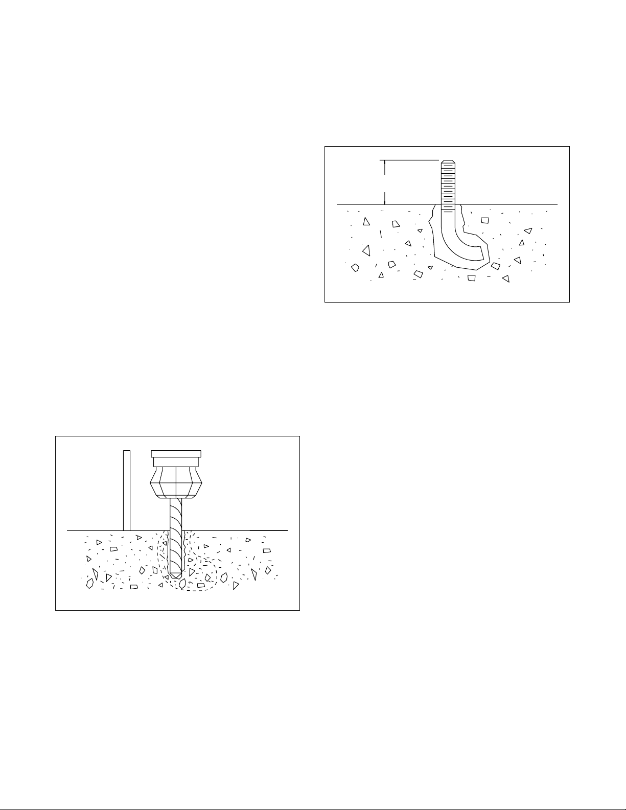
5. Use compressed air or a squeeze bulb to remove
debris from each hole. Anchor J-bolt in place,
using an industry-accepted anchoring compound.
Verify that the J-bolts are in the correct locations
and that 1-1/2 inches (38 mm) of each J-bolt
protrude from the floor. Refer to Figure 15.
1-1/2 in.
(38 mm)
H032I
Figure 15
6. Place the machine carefully over the J-bolts.
Never attempt to lift the machine by the door
handle or by pushing on the cover panels.
3. Adjust the drill depth gauge to match the length
of the J-bolt, minus 1-1/2 inches (38 mm).
4. Drill and chisel out a conical hole large enough to
accept the J-bolt. Refer to Figure 14.
H031I
H031I
Figure 14
28
© Copyright, Alliance Laundry Systems LLC – DO NOT COPY or TRANSMIT
F232135
Page 31

7. If grouting is not desired, position washers and
locknuts on J-bolts and tighten the locknuts by
even increments – one after the other – until all
are tightened evenly and the machine is fastened
securely to the floor. Refer to Figure 16.
8. If grouting is desired (or required by the
condition of the mounting surface), proceed
to step 11.
9. If the machine is a variable-speed model, the
machine must be grouted. Proceed to step 11.
Installation
10. Raise and level the machine 1/2 inch (13 mm) off
the floor on three points, using spacers such as
nut fasteners.
11. Fill the space between the machine base and the
floor with a good quality non-shrinking
machinery grout to ensure a stable installation.
Grout completely under all frame members.
12. Remove the spacers carefully, allowing the
machine to settle into the wet grout.
13. Before grout sets completely, make a drain
opening in the rear of the machine grouting with
a stiff piece of wire. This opening should be
approximately 1/2 inch (13 mm) wide to allow
any surface water build-up under the base of the
machine to drain away. Do not omit this step.
14. Position washers and locknuts on J-bolts and
fingertighten nuts to machine base.
15. After the grout is completely dry, tighten the
locknuts by even increments – one after the
other – until all are tightened evenly and the
machine is fastened securely to the floor.
16. Balance Switch Adjustment: After mounting,
reset balance switch to the correct gap switch
setting. Refer to Table 1 .
NOTE: Be sure to recheck the J-bolts 1 week after
installation.
H033I
H033I
Figure 16
Figure 17 shows the completed J-bolt installation with
grout.
2
1
1-1/2 in.
(38 mm)
1 Foundation
2 Locknut
3 Machine Base
4 1/2 in. (13 mm) Machinery Grout
5 J-Bolt
3
Figure 17
4
5
U139I
U139I
F232135
© Copyright, Alliance Laundry Systems LLC – DO NOT COPY or TRANSMIT
29
Page 32

Installation
Mounting Bolt Template Part
Numbers (Without Elevated Base
Frame)
Metal templates are available at cost through Alliance
Laundry Systems at (920) 748-3121. Refer to Tabl e 5
for specific Part Numbers when ordering.
Machine Part No.
18/20 F608707
25 F608708
27/30 F631796
35 F608709
40 F0637047-00
50/60 F608710
80 F609692
125 F601862
Table 5
30
© Copyright, Alliance Laundry Systems LLC – DO NOT COPY or TRANSMIT
F232135
Page 33

Mounting Bolt Hole Locations (Without Elevated Base Frames)
26 in.
(660 mm)
26 in.
(660 mm)
Installation
2.68 in.
(68 mm)
31.75 in.
23.94 in.
(608 mm)
2.56 in.
0.75 in.
(19 mm)
(65 mm)
2.75 in.
(70 mm)
28.94 in.
(735 mm)
18.44 in.
(468 mm)
(806 mm)
20.88 in.
(530 mm)
18 AND 20 POUND
29 in.
(737 mm)
23.5 in.
(597 mm)
37.52 in.
(953 mm)
30.02 in.
(762 mm)
26 in.
2.56 in.
(65 mm)
2.75 in.
(70 mm)
(660 mm)
0.75 in.
(19 mm)
31.5 in.
(800 mm)
36 in.
27.94 in.
(710 mm)
2.56 in.
(65 mm)
3.28 in.
(83 mm)
(914 mm)
18.31 in.
(465 mm)
24.07 in.
(611 mm)
20.66 in.
(525 mm)
34.88 in.
(885 mm)
25 POUND
(700 mm)
(1191 mm)
27.69 in.
(705 mm)
20.88 in.
(530 mm)
34.06 in.
(865 mm)
27.5 in.
46.88 in.
37.44 in.
(951 mm)
2.68 in.
(68 mm)
3.28 in.
(83 mm)
30 in.
(762 mm)
2.56 in.
(65 mm)
37.5 in.
(953 mm)
0.75 in.
2.56 in.
(65 mm)
(19 mm)
23.88 in.
(607 mm)
27 AND 30 POUND
2.56 in.
(65 mm)
0.75 in.
(19 mm)
2.03 in.
(52 mm)
*For close mounting, use mounting bolt pattern labeled “A”; for standard mounting, use “B.”
Figure 18
F232135
© Copyright, Alliance Laundry Systems LLC – DO NOT COPY or TRANSMIT
30 in.
(760 mm)
50 POUND
2.03 in.
(52 mm)
CHM2020N
31
Page 34

Installation
Mounting Bolt Hole Locations (Without Elevated Base Frames)
34.06 in.
(865 mm)
17 in.
(432 mm)
28.5 in.
(724 mm)
32.5 in.
0.75 in.
4 in.
(102 mm)
5 in.
(127 mm)
0.75 in.
(19 mm)
4 in.
(102 mm)
36 in.
0.75 in.
(826 mm)
(19 mm)
3.28 in.
(83 mm)
(914 mm)
24.07 in.
2.03 in.
(52 mm)
(19 mm)
3.25 in.
(83 mm)
20 in.
(508 mm)
2.06 in.
(52 mm)
(611 mm)
27.5 in.
(700 mm)
46.88 in.
(1191 mm)
60 POUND
23.63 in.
(600 mm)
41.63 in.
(1057 mm)
35 POUND
33.5 in.
(851 mm)
A A
B B
B B
40 in.
(1016 mm)
31.5 in.
(800 mm)
37.44 in.
(951 mm)
30 in.
(760 mm)
30.13 in.
(765 mm)
31.88 in.
(810 mm)
26 in.
(660 mm)
AA
AAB B
3.28 in.
(83 mm)
CHM2005N
3.25 in.
(83 mm)
2.06 in.
(52 mm)
4 in.
(102 mm)
5 in.
(127 mm)
0.75 in.
(19 mm)
4 in.
(102 mm)
37.5 in.
2.03 in.
(52 mm)
CHM2005N
34 in.
(864 mm)
1 in.
(25 mm)
9.5 in.
(241 mm)
11 in.
(279 mm)
25 in.
(635 mm)
(953 mm)
47.5 in.
(1207 mm)
32.5 in.
(826 mm)
1.5 in.
(38 mm)
48 in.
(1219 mm)
20 in.
(508 mm)
0.75 in.
(19 mm)
41.63 in.
(1057 mm)
23.63 in.
(600 mm)
31.88 in.
(810 mm)
26 in.
(660 mm)
30.13 in.
(765 mm)
40 POUND
46.5 in.
(1181 mm)
61.5 in.
(1562 mm)
55.47 in.
(1409 mm)
48.94 in.
(1243 mm)
3.25 in.
(83 mm)
(914 mm)
36 in.
2.06 in.
(52 mm)
0.75 in.
(19 mm)
10 in.
(254 mm)
(381 mm)
15.25 in.
(388 mm)
15 in.
1 in.
(25 mm)
33.5 in.
(851 mm)
41.5 in.
(1054 mm)
23.25 in.
(591 mm)
(1219 mm)
80 POUND* 125 POUND
*For close mounting, use mounting bolt pattern labeled “A”; for standard mounting, use “B.”
Figure 19
32
© Copyright, Alliance Laundry Systems LLC – DO NOT COPY or TRANSMIT
48 in.
23.25 in.
(591 mm)
0.75 in.
(19 mm)
CHM2018N
F232135
Page 35

Mounting Bolt Hole Locations (With Elevated Base Frames)
26.4 in.
2.87 in.
(73 mm)
(670 mm)
2.87 in.
(73 mm)
26.4 in.
(670 mm)
Installation
23.94 in.
(608 mm)
2.75 in.
1.13 in.
(29 mm)
(70 mm)
(75 mm)
28.94 in.
(735 mm)
14.31 in.
(363 mm)
2.94 in.
18.44 in.
31.75 in.
(806 mm)
(530 mm)
18 AND 20 POUND
(597 mm)
(468 mm)
20.66 in.
(525 mm)
25.22 in.
(640 mm)
20.88 in.
29.4 in.
(747 mm)
23.5 in.
37.52 in.
(953 mm)
30.02 in.
(762 mm)
26.2 in.
2.75 in.
(70 mm)
2.94 in.
(75 mm)
2.87 in.
(73 mm)
27.94 in.
(665 mm)
1.13 in.
(29 mm)
31.2 in.
(792 mm)
(710 mm)
18.31 in.
(465 mm)
2.75 in.
(70 mm)
3.44 in.
(87 mm)
32.5 in.
(826 mm)
20 in.
(508 mm)
20.66 in.
(525 mm)
34.88 in.
(885 mm)
25 POUND
(1057 mm)
27.69 in.
(705 mm)
20.88 in.
(530 mm)
30.5 in.
(775 mm)
23.63 in.
(600 mm)
41.63 in.
31.88 in.
(810 mm)
2.87 in.
(73 mm)
3.44 in.
(87 mm)
30.2 in.
(767 mm)
2.75 in.
(70 mm)
34.75 in.
(883 mm)
2.75 in.
(70 mm)
1.13 in.
(29 mm)
2.25 in.
(57 mm)
1.13 in.
2.75 in.
(70 mm)
(29 mm)
23.88 in.
(607 mm)
27 AND 30 POUND
*For close mounting, use mounting bolt pattern labeled “A”; for standard mounting, use “B.”
Figure 20
F232135
© Copyright, Alliance Laundry Systems LLC – DO NOT COPY or TRANSMIT
26 in.
(660 mm)
35 POUND
2.25 in.
(57 mm)
CHM2021N
CHM2021N
33
Page 36

Installation
Mounting Bolt Hole Locations (With Elevated Base Frames)
32.5 in.
(826 mm)
2.38 in.
(61 mm)
20 in.
(508 mm)
3.47 in.
(88 mm)
3.62 in.
(92 mm)
36 in.
(914 mm)
2.44 in.
(62 mm)
3.47 in.
(88 mm)
36 in.
(914 mm)
24 in.
(610 mm)
2.22 in.
(56 mm)
1.13 in.
(29 mm)
27.5 in.
(700 mm)
46.88 in.
(1191 mm)
41.63 in.
(1057 mm)
23.63 in.
(600 mm)
31.88 in.
(810 mm)
26 in.
(660 mm)
30.88 in.
(784 mm)
40 POUND 50 POUND
34.5 in.
(876 mm)
27.5 in.
(700 mm)
3.47 in.
(88 mm)
34.5 in.
(876 mm)
37.44 in.
(951 mm)
30 in.
(762 mm)
3.47 in.
(88 mm)
38.25 in.
2.22 in.
(56 mm)
(972 mm)
46.88 in.
(1191 mm)
36 in.
(914 mm)
24 in.
(610 mm)
2.22 in.
(56 mm)
2.13 in.
(54 mm)
37.44 in.
(951 mm)
30 in.
(762 mm)
60 POUND
38.9 in.
2.22 in.
(56 mm)
(988 mm)
*For close mounting, use mounting bolt pattern labeled “A”; for standard mounting, use “B.”
Figure 21
CHM2022N
CHM2022N
34
© Copyright, Alliance Laundry Systems LLC – DO NOT COPY or TRANSMIT
F232135
Page 37

Installation
Elevated Base Frame Installation
Factory-built elevated steel base frames are designed
to meet the specifications of the 20-60 2 speed,
F speed and A-control variable-speed model washerextractor only. Refer to Figure 22.
3. Adjust the drill depth gauge to match the length
of the J-bolt, minus 1-1/2 inches (38 mm).
4. Drill and chisel out a conical hole large enough to
accept the J-bolt. Refer to Figure 23.
H031I
H031I
Figure 23
5. Use compressed air or a squeeze bulb to remove
debris from each hole. Anchor J-bolt in place,
using an industry-accepted anchoring compound.
Verify that the J-bolts are in the correct locations
and that 1-1/2 inches (38 mm) of each J-bolt
protrude from the floor. Refer to Figure 24.
Figure 22
Installing With Elevated Base Frame
1. Verify the floor meets the requirements given in
the Machine Foundation section.
2. Use the elevated base frame as a template by
positioning the frame in the desired location and
marking the pre-drilled mounting holes on the
floor.
H035I
1-1/2 in.
(38 mm)
H032I
Figure 24
F232135
© Copyright, Alliance Laundry Systems LLC – DO NOT COPY or TRANSMIT
35
Page 38

Installation
6. Raise and level the base frame 1/2 inch (13 mm)
off the floor on three points, using spacers such
as nut fasteners.
7. Fill the space between the frame base and the
floor with a good quality non-shrinking
machinery grout to ensure a stable installation.
Grout completely under all frame members.
8. Remove the spacers carefully, allowing the base
frame to settle into the wet grout.
9. Before grout sets completely, make a drain
opening in the rear of the base frame grouting
with a stiff piece of wire. This opening should be
approximately 1/2 inch (13 mm) wide to allow
any surface water build-up under the base of the
machine to drain away. Do not omit this step.
10. Position washers and locknuts on J-bolts and
fingertighten nuts to base frame.
11. After the grout is completely dry, tighten locknuts
by even increments – one after the other – until
all are tightened evenly and the base frame is
fastened securely to the floor. Refer to Figure 16.
12. Position the machine over the base frame, aligning
the mounting holes on the machine with the
corresponding holes on the frame.
13. Install a bolt, lockwasher, and nut in each
mounting hole. Use 5/8 inch – 18 x 2
grade 5 mounting bolts with 5/8 inch – 18
grade B nuts and 5/8 inch lockwashers.
14. Handtighten each nut.
15. Tighten the two rear nuts two turns.
16. Tighten the two front nuts two turns.
17. On 25, 27, 30, 35, 40, 50 and 60 models, tighten
the two middle nuts firmly.
18. Tighten the two front nuts firmly; tighten the two
rear nuts firmly.
NOTE: Recheck the elevated base frame
installation one week after installation.
36
© Copyright, Alliance Laundry Systems LLC – DO NOT COPY or TRANSMIT
F232135
Page 39

Installation
Concrete Foundation Installation
A concrete foundation pad may be constructed to
elevate the machines. Refer to Figure 25, Figure 26 or
Figure 27 for a typical concrete foundation
installation.
NOTE: Expansion bolts should not be used in
single-machine concrete foundation installations.
1. Verify that the floor meets the requirements given
in the Machine Foundation section.
2. Excavate the floor to a depth of approximately
9 inches (230 mm) below the floor surface,
making certain that the sides of the hole slope
outwards from top to bottom. The bottom of the
hole should be 6 inches (152 mm) larger all
around than the top.
NOTE: When installation is complete, the top
of the foundation should extend a minimum of
4 inches (102 mm) out from the machine on all
sides.
3. Wet the hole well and brush the bottom and sides
with cement grout.
2
1
18, 20, 25, 27, 30, 35, 40, 50 AND 60 POUND CAPACITY MODELS
1 Pad height must not exceed 8 in. (203 mm)
2 1 in. (25 mm) Minimum
3 4 in. (102 mm) Minimum
3
3
CHM2033N
CHM2033N
Figure 25
F232135
© Copyright, Alliance Laundry Systems LLC – DO NOT COPY or TRANSMIT
37
Page 40

Installation
1
2
LENGTH FOR ONE MACHINE
2
34
2
COMPACTED FILL DIRT 18 in. (457 mm) DEPTH
COMPACTED FILL DIRT 18 in. (457 mm) DEPTH
80 POUND CAPACITY MODELS
1 9 in. (229 mm) 3 47-1/2 in. (1207 mm)
2 6 in. (152 mm) 4 4 ft. 6 in. (1372 mm)
Figure 26
1
2
1
3
1
LENGTH FOR ONE MACHINE
B153I
B153I
4
COMPACTED FILL DIRT 24 in. (609 mm) DEPTH
COMPACTED FILL DIRT 24 in. (609 mm) DEPTH
125 POUND CAPACITY MODELS
1 12 in. (305 mm) 3 48 in. (1219 mm)
2 6 in. (152 mm) 4 6 ft. (1829 mm)
Figure 27
38
© Copyright, Alliance Laundry Systems LLC – DO NOT COPY or TRANSMIT
B154I
B154I
F232135
Page 41

Installation
4. Use rebar or other appropriate material to ensure
that the concrete foundation will be sufficiently
connected to the existing floor.
5. If desired, prepare a form for the above-ground
portion of the foundation and fill form and
excavation with concrete to join the foundation.
Verify that top of foundation is level. The height
of the foundation must not exceed 8 inches
(203 mm).
6. Use the mounting bolt layout to properly position
the mounting bolts in the wet concrete. When
using J-bolts, allow 1-1/2 inches
(38 mm) to extend above the surface of the
concrete.
7. Allow concrete to dry.
8. Place the machine carefully over the mounting
bolts. Never attempt to lift the machine by the
door handle or by pushing on the cover panels.
NOTE: Grouting provides a uniform mounting
surface. Grouting is optional for 2 speed models
and is required for variable-speed models installed
on a concrete foundation. If grouting is not
required, proceed to step 13.
9. Raise and level the machine 1/2 inch (13 mm) off
the foundation on three points, using spacers
such as nut fasteners.
10. Fill the space between the machine base and the
foundation with a good quality non-shrinking
machinery grout to ensure a stable installation.
Grout completely under all frame members.
11. Remove the spacers carefully, allowing the
machine to settle into the wet grout.
12. Before grout sets completely, make a drain
opening in the rear of the machine grouting with
a stiff piece of wire. This opening should be
approximately 1/2 inch (13 mm) wide to allow
any surface water build-up under the base of the
machine to drain away. Do not omit this step.
13. Position washers and locknuts on J-bolts or
mounting bolts and fingertighten nuts to machine
base.
14. After the grout is completely dry, tighten the
locknuts by even increments – one after the
other – until all are tightened evenly and the
machine is fastened securely to the concrete
foundation.
F232135
© Copyright, Alliance Laundry Systems LLC – DO NOT COPY or TRANSMIT
39
Page 42

Installation
Drain Connection
Use the supplied black rubber adapter and clamps to
transition from the machine drain outlet to the two
Figure 28 and Figure 29 show typical drain trough and
drain line installations.
Connect the drain outlet to a vented drain system using
only a flexible connection. The drain system must be
vented to prevent an air lock or siphoning.
inch schedule 40 PVC plumbing (20, 25 and 30
models) and the three inch schedule PVC plumbing
(40, 60 and 80 models).
If proper drain size is not available or practical, a surge
tank is required. A surge tank along with a sump pump
should be used when gravity drainage is not possible,
such as in below-ground-level installations.
DRAIN TROUGH
2
1
1 Drain Hose 4 Drain Tee
2 Drain Valve 5 Floor
3 Overflow Hose 6 Open Drain Trough
3
4
5
6
H050I
H050I
Figure 28
4
6*
1 ft.
(0.3 m)
3
DRAIN LINE
2
1
1 Drain Hose 4 Overflow Hose
2 Drain Valve 5 Vent Pipe
3 Drain Tee 6 Water Inlet Valve*
* 1 foot (0.3 m) minimum between water inlet valve and vent pipe.
Figure 29
5*
CHM2010N
40
© Copyright, Alliance Laundry Systems LLC – DO NOT COPY or TRANSMIT
F232135
Page 43

Installation
IMPORTANT: Increasing the drain hose length,
installing elbows, or causing bends will decrease
drain flow rates and increase drain times,
impairing machine performance.
Drain Information
18, 20 25 27, 30 35 40 50 60 80 125
Drain connection
size, OD
Number of drain
outlets
Drain flow
capacity
Recommended
drain pit size
* Also works with 3 inch OD PVC pipe if connected to inside of
drain tee connector.
2.38 in.
(60 mm)
111111111
20 gal-min
(76 l-min)
1.80 ft
(51 l)
3
2.38 in.
(60 mm)
25 gal-min
(95 l-min)
3
2.36 ft
(66.8 l)
2.38 in.
(60 mm)
25 gal-min
(95 l-min)
3
2.50 ft
(70.3 l)
2.38 in.
(60 mm)
35 gal-min
(132 l-min)
3.14 ft
(88.9 l)
Drain Line Sizing
Minimum Drain ID
Refer to Table 6 for capacity-specific drain
information.
NOTE: Installation of additional machines will
require larger drain connections. Refer to Table 7.
3
Table 6
3.5 in.*
(89 mm)
50 gal-min
(189 l-min)
4.52 ft
(128 l)
3
3.5 in.*
(89 mm)
50 gal-min
(189 l-min)
3
4.52 ft
(128 l)
3.5 in.*
(89 mm)
50 gal-min
(189 l-min)
3
4.52 ft
(128 l)
3.5 in.*
(89 mm)
50 gal-min
(189 l-min)
5.90 ft
(169 l)
3
3.5 in.*
(89 mm)
70 gal-min
(265 l-min)
3
13 ft
(368 l)
Model
18, 20
25
27, 30
35
40
50
60
80, 125
Number of Machines
12345
2
in. (52 mm) 3 in. (76 mm) 3 in. (76 mm) 4 in. (102 mm) 4 in. (102 mm)
2
in. (52 mm) 3 in. (76 mm) 3 in. (76 mm) 4 in. (102 mm) 4 in. (102 mm)
2
in. (52 mm) 3 in. (76 mm) 3 in. (76 mm) 4 in. (102 mm) 4 in. (102 mm)
in. (76 mm) 3 in. (76 mm) 3-1/2 in. (89 mm) 4 in. (102 mm) 4 in. (102 mm)
3
in. (76 mm) 4 in. (102 mm) 4 in. (102 mm) 4 in. (102 mm) 6 in. (152 mm)
3
3
in. (76 mm) 4 in. (102 mm) 4 in. (102 mm) 4 in. (102 mm) 6 in. (152 mm)
3
in. (76 mm) 4 in. (102 mm) 4 in. (102 mm) 4 in. (102 mm) 6 in. (152 mm)
3
in. (76 mm) 4 in. (102 mm) 4 in. (102 mm) 6 in. (152 mm) 6 in. (152 mm)
Table 7
F232135
© Copyright, Alliance Laundry Systems LLC – DO NOT COPY or TRANSMIT
41
Page 44

Installation
Water Connection Requirements
Connections should be supplied by a hot and a cold
water line of at least the sizes shown in Table 8.
Installation of additional machines will require
proportionately larger water lines.
To connect water service to machine with rubber
hoses, use the following procedure:
1. Before installing hoses, flush the water system
for at least 2 minutes.
2. Check filters in the machine’s inlet hoses for
proper fit and cleanliness before connecting.
3. Hang hoses in a large loop; do not allow them to
kink.
If additional hose lengths are needed, use flexible
hoses with screen filters.
Model
18 – 60
80
125
Water Supply Line Sizing
Number
of
Machines
13/4 in. (19 mm) 1/2 in. (13 mm)
21
31-1/4
41-1/2
11 in. (25 mm) 3/4 in. (19 mm)
21-1/2
32
42
11-1/2 in. (38 mm) 1 in. (25 mm)
22
32
42-1/2
Supply Line Size
Main Hot/Cold
in. (25 mm) 3/4 in. (19 mm)
in. (32 mm) 1 in. (25 mm)
in. (38 mm) 1 in. (25 mm)
in. (38 mm) 1 in. (25 mm)
in. (50 mm) 1-1/4 in. (32 mm)
in. (50 mm) 1-1/2 in. (38 mm)
in. (50 mm) 1-1/2 in. (38 mm)
in. (50 mm) 2 in. (50 mm)
in. (70 mm) 2 in. (50 mm)
Suitable air cushions should be installed in supply
lines to prevent “hammering.” Refer to Figure 30.
2
1
MW008J
1 Water Supply Faucets
2 Air Cushions (Risers)
Figure 30
42
Table 8
© Copyright, Alliance Laundry Systems LLC – DO NOT COPY or TRANSMIT
F232135
Page 45

Installation
Hazardous Voltage. Can cause shock,
burn or cause death. Allow machine
power to remain off for two minutes prior
to working in and around AC inverter
drive.
W359
WARNING
Hazardous Voltage. Can cause shock,
burn or death. Verify that a ground wire
from a proven earth ground is connected
to the lug near the input power block on
this machine.
W360
WARNING
Electrical Installation Requirements
IMPORTANT: Electrical ratings are subject to
change. Refer to serial decal for electrical ratings
information specific to your machine.
IMPORTANT: Alliance Laundry Systems
warranty does not cover components that fail as a
result of improper input voltage.
IMPORTANT: Improper connections will result in
equipment damage and will void warranty.
IMPORTANT: For machines with X voltage: If
input power is single-phase, connect L1 to R of
terminal block and L2 to S of terminal block. Leave
T unconnected on the input terminal block. If input
power is three-phase, connect L1, L2 and L3 to R, S
and T of the terminal block.
DANGER
Hazardous Rotation Speed. Will cause
serious injury when controlling AC
inverter drive with a parameter unit,
safety features are bypassed allowing
basket to rotate at high speeds with the
door open. Place large sign on front of
machine to warn people of imminent
danger.
W361
Machines equipped with an AC inverter drive require a
clean power supply, free from voltage spikes and
surges. Use voltage monitor to check incoming power.
The customer’s local power company may provide
such a monitor.
Input Voltage Requirements
If input voltage measures above rated maximum
voltage, ask the power company to lower voltage.
For voltages above or below listed specifications,
contact Customer Service or a distributor for buck/
boost transformer recommendation. Refer to
Electrical Specification section.
If machine is intended for four-wire service, a neutral
leg must be provided by power company.
If a delta supply system is used on a four-wire model,
connect high leg to L3.
Circuit Breakers
Single-phase machines require a single-phase inversetime circuit breaker. Three-phase machines and
variable-speed machines require a separate, threephase inverse-time circuit breaker to prevent damage
to the motor by disconnecting all legs if one should
be lost accidentally. Check the nameplate decal on
the back of the machine. Refer to Table 9 through
Table 16 in this section for model-specific circuit
breaker requirements.
F232135
© Copyright, Alliance Laundry Systems LLC – DO NOT COPY or TRANSMIT
43
Page 46

Installation
Connection Specifications
IMPORTANT: Connection must be made by a
qualified electrician using wiring diagram provided
with machine, or according to accepted European
standards for CE-approved equipment.
Connect machine to an individual branch circuit not
shared with lighting or other equipment. Shield
connection in a liquid-tight or approved flexible
conduit. Proper conductors of correct size must be
installed in accordance with National Electric Code or
other applicable codes.
Use wire sizes indicated in the Electrical Specifications
chart for runs up to 50 feet (15 m). Use next larger size
for runs of 50 to 100 feet (15 to 30 m). Use two sizes
larger for runs greater than 100 feet (30 m).
Grounding
For personal safety and proper operation, the machine
must be grounded in accordance with state and local
codes. If such codes are not available, grounding must
conform to the National Electric Code, article 250-95.
The ground connection must be made to a proven earth
ground, not to conduit or water pipes.
Phase Adder
If three-phase service is unavailable for a 2 speed
model and a Roto-Phase or other phase adder is used,
connect artificial leg to L3 in input power junction
box.
IMPORTANT: Do not use a phase adder on any
variable-speed machine.
Thermal Overload Protector
Two speed machines have thermal overload protectors
in drive motor windings and a separate fuse for control
circuit.
For variable-speed machines, the AC drive provides
overload protection for the drive motor.
Do not connect ground to neutral (N-white wire) leg at
terminal strip.
44
© Copyright, Alliance Laundry Systems LLC – DO NOT COPY or TRANSMIT
F232135
Page 47

Electrical Specifications
18 and 20 Pound Capacity Models
Installation
Code
Voltage Designation Standard Electric Heat
Volta ge
Cycle
Phase
Wire
Full Load
Amps
Breaker
Circuit
AWG
mm
2
Full Load
Breaker
Amps
Circuit
AWG
mm
2
2 Speed Models
B 110 – 120 60 1 2 15 20 12 4 N/A
C 380 – 415 50 3 4 4 15 14 2.5 14 15 14 2.5
D 220 – 240 50 3 3 5 15 14 2.5 24 25 10 6
E220 – 2405012102012 4 4245 6 16
F 440 – 480 60 3 3 4 15 14 2.5 16 20 12 4
H 380 60 3 3 4 15 14 2.5 13 15 14 2.5
J 200 50 3 3 5 15 14 2.5 24 25 10 6
O 208 – 240 60 3 3 5 15 14 2.5 24 25 10 6
Y208 – 2406012102012 4 4245 6 16
Variable-Speed Models
Q 200 – 240 50/60 3 3.8 3.8 15 14 2.5 N/A N/A N/A N/A
NOTE: Wire sizes shown are for copper, THHN, 90° conductor per NEC article 310.
Table 9
25, 27 and 30 Pound Capacity Models
Electrical Specifications
Code
Voltage Designation Standard Electric Heat
Voltag e
Cycle
Phase
Wire
Full Load
Amps
Breaker
Circuit
AWG
mm
2
Full Load
Amps
Breaker
Circuit
AWG
mm
2
2 Speed Models
C 380 – 415 50 3 4 4 15 14 2.5 15 20 12 4
D 220 – 240 50 3 3 6 15 14 2.5 24 25 10 6
E220 – 2405012102012 4 4245 6 16
F 440 – 480 60 3 3 4 15 14 2.5 16 20 12 4
H 380 60 3 3 4 15 14 2.5 14 15 14 2.5
J 200 50 3 3 6 15 14 2.5 20 25 10 6
O 208 – 240 60 3 3 7 15 14 2.5 25 30 10 6
Y 208 – 240 60 1 2 10 20 12 4 43
45616
Variable-Speed Models
Q 200 – 240 50/60 3 3 4.8 15 14 2.5 N/A N/A N/A N/A
NOTE: Wire sizes shown are for copper, THHN, 90° conductor per NEC article 310.
F232135
Tabl e 1 0
© Copyright, Alliance Laundry Systems LLC – DO NOT COPY or TRANSMIT
45
Page 48

Installation
Electrical Specifications
35 Pound Capacity Models
Code
Voltage Designation Standard Electric Heat
Voltag e
Cycle
Phase
Wire
Full Load
Amps
Breaker
Circuit
AWG
mm
2
Full Load
Amps
Breaker
Circuit
AWG
2 Speed Models
C 380 – 415 50 3 4 5 15 14 2.5 26 30 10 6
D 220 – 240 50 3 3 7 20 12 4 43 50 6 16
F 440 – 480 60 3 3 5 15 14 2.5 26 30 10 6
O 200 – 240 60 3 3 7 20 12 4 43 50 6 16
Y 208 – 240 60 1 2 12 25 10 6 N/A
Variable-Speed Models
N 440 – 480 50/60 3 3 2.3 15 14 2.5 27.3 30 10 6
P 380 – 415 50/60 3 3 2.3 15 14 2.5 24 25 10 6
Q 208 – 240 50/60 3 3 5.9 15 14 2.5 43.4 45 6 16
T 200 – 240 50/60 1 2 5.9 15 14 2.5 N/A
X 200 – 240 50/60 1 or 3 2 or 3 5.9/5.9 15 14 2x2.5
N/A
3x2.5
NOTE: Wire sizes shown are for copper, THHN, 90° conductor per NEC article 310.
Tabl e 1 1
mm
2
Electrical Specifications
40 Pound Capacity Models
Code
Voltage Designation Standard Electric Heat
Voltag e
Cycle
Phase
Wire
Full Load
Amps
Breaker
Circuit
AWG
mm
2
Full Load
Amps
Breaker
Circuit
AWG
mm
2
2 Speed Models
C 380 – 415 50 3 4 5 15 14 2.5 26 30 10 6
D 220 – 240 50 3 3 7 20 12 4 45 50 6 16
F 440 – 480 60 3 3 5 15 14 2.5 29 30 10 6
H 380 60 3 3 3 15 14 2.5 25 30 10 6
J 200 50337201243840616
O 208 – 240 60 3 3 7 20 12 4 45 50 6 16
Y 208 – 240 60 1 2 13.5 30 10 6 N/A
Variable-Speed Models
N 440 – 480 50/60 3 3 6 15 14 2.5 30 30 10 6
P 380 – 415 50/60 3 3 6 15 14 2.5 29 30 10 6
Q 200 – 240 50/60 3 3 5 15 14 2.5 48 60 6 16
X 200 – 240 50/60 1 or 3 2 or 3 11/11 15 14 2.5 N/A
NOTE: Wire sizes shown are for copper, THHN, 90° conductor per NEC article 310.
46
Tabl e 1 2
© Copyright, Alliance Laundry Systems LLC – DO NOT COPY or TRANSMIT
F232135
Page 49

Electrical Specifications
50 Pound Capacity Models
Installation
Code
Voltage Designation Standard Electric Heat
Volta ge
Cycle
Phase
Wire
Full Load
Amps
Breaker
Circuit
AWG
mm
2
Full Load
Breaker
Amps
Circuit
AWG
mm
2
2 Speed Models
C 380 – 415 50 3 4 6 15 14 2.5 39 50 6 16
D220 – 2405033122012 4 6470 4 25
E220 – 2405012153010 6 3740 8 10
F 440 – 480 60 3 3 6 15 14 2.5 39 50 6 16
J 200 50 3 3 10 20 12 3 x 4 N/A
O208 – 2406033102012 4 6470 4 25
Y*208 – 2406012153010 6 3740 8 10
Variable-Speed Models
N 440 – 480 50/60 3 3 4 15 14 2.5 41.6 45 8 10
P 380 – 415 50/60 3 3 4 15 14 2.5 36.5 40 8 10
Q 200 – 240 50/60 3 3 6.3 15 14 2.5 62.6 70 4 25
T 200 – 240 50/60 1 2 6.3 15 14 2.5 N/A
X 200 – 240 50/60 1 or 3 2 or 3 6.3/6.3 15 14 2x2.5
N/A
3x2.5
NOTE: Wire sizes shown are for copper, THHN, 90° conductor per NEC article 310.
*Coin models only.
Tabl e 1 3
F232135
© Copyright, Alliance Laundry Systems LLC – DO NOT COPY or TRANSMIT
47
Page 50

Installation
Electrical Specifications
60 Pound Capacity Models
Code
Voltage Designation Standard Electric Heat
Volta ge
Cycle
Phase
Wire
Full Load
Amps
Breaker
Circuit
AWG
mm
2
Full Load
Breaker
Amps
Circuit
AWG
2 Speed Models
C 380-415 50 3 4 4 15 14 2.5 37 50 8 10.0
D 220-240 50 3 3 7 20 12 4.0 64 70 4 25.0
F 440-480 60 3 3 4 15 14 2.5 41 50 8 10.0
H 380 60 3 3 3 20 12 4.0 33 50 8 10.0
J 200 50 3 3 8 20 12 4.0 55 60 6 16.0
O 208-240 60 3 3 7 20 12 4.0 64 70 4 25.0
X 200-240 50/60 1/3 2/3 9 20 12 4.0 N/A N/A N/A N/A
Variable-Speed Models
N 440-480 50/60 3 3 4 15 14 2.5 42 50 8 10.0
P 380-415 50/60 3 3 5 15 14 2.5 37 40 8 10.0
Q 200-240 50/60 3 3 6 15 14 2.5 65 60 6 16.0
X 200-240 50/60 1/3 2/3 10 20 12 4.0 N/A N/A N/A N/A
NOTE: Wire sizes shown are for copper, THHN, 90° conductor per NEC article 310.
mm
2
Tabl e 1 4
48
© Copyright, Alliance Laundry Systems LLC – DO NOT COPY or TRANSMIT
F232135
Page 51

Electrical Specifications
80 Pound Capacity Models
Installation
Code
Voltage Designation Standard Electric Heat
Volta ge
Cycle
Phase
Wire
Full Load
Amps
Breaker
Circuit
AWG
mm
2
Full Load
Breaker
Amps
Circuit
AWG
Variable-Speed Models
N 440 – 480 50/60 3 3 4.5 15 14 2.5 42 45 8 10
P 380 – 415 50/60 3 3 4.5 15 14 2.5 37 40 8 10
Q 200 – 240 50/60 3 3 12.4 20 12 4 87.4 90 2 35
NOTE: Wire sizes shown are for copper, THHN, 90° conductor per NEC article 310.
Tabl e 1 5
Electrical Specifications
125 Pound Capacity Models
Code
Voltage Designation Standard Electric Heat
Voltag e
Cycle
Phase
Wire
Full Load
Amps
Breaker
Circuit
AWG
mm
2
Full Load
Amps
Breaker
Circuit
AWG
Variable-Speed Models
N 440 – 480 50/60 3 3 5.1 15 14 2.5 N/A
P 380 – 415 50/60 3 3 5.1 15 14 2.5 N/A
Q 200 – 240 50/60 3 3 7.9 25 10 6 N/A
NOTE: Wire sizes shown are for copper, THHN, 90° conductor per NEC article 310.
mm
2
mm
2
Tabl e 1 6
F232135
© Copyright, Alliance Laundry Systems LLC – DO NOT COPY or TRANSMIT
49
Page 52

Installation
Troubleshooting
If machine fails to operate after power is connected,
proceed as follows:
1. Disconnect power.
2. Unlock and raise top cover.
3. Check circuit fuse.
For mechanical timer, P-computer and
S-computer models, control circuit fuse is located
on center brace.
For EDC and V-computer models, dual control
circuit fuses (one primary, one secondary) are in
control module. A decal identifies fuse(s) and
provides fuse-rating appropriate to that specific
model.
For NetMaster models, circuit fuses are located
on side of control box.
For A-control and B-control models, circuit fuses
are located on the output board.
4. If control circuit fuse has blown, replace with
fuse of appropriate rating as identified by decal.
IMPORTANT: Call a qualified electrician if
replacement fuse blows.
Steam Requirements
(Steam Heat Option Only)
WARNING
Hot Surfaces. Will cause severe burns.
Turn steam off and allow steam pipes,
connections and components to cool
before touching.
For machines equipped with optional steam heat,
install piping in accordance with approved commercial
steam practices. Steam requirements are shown in
Table 17.
Steam Supply Information
Steam inlet
connection size
Number of steam inlets 1
Recommended pressure 30 – 80 psi
Maximum pressure 80 psi
18 – 80 pound 1/2
125 pound 3/4
(2.0 – 5.4 bar)
Table 17
W505
in. (13 mm)
in. (19 mm)
(5.4 bar)
IMPORTANT: Failure to install the customer
supplied steam filter may void the warranty.
50
© Copyright, Alliance Laundry Systems LLC – DO NOT COPY or TRANSMIT
F232135
Page 53

Installation
Dangerous Chemicals. May damage eyes
and skin. Wear eye and hand protection
when handling chemicals; always avoid
direct contact with raw chemicals. Read
the manufacturer’s directions for
accidental contact before handling
chemicals. Ensure an eye-rinse facility
and an emergency shower are within easy
reach. Check at regular intervals for
chemical leaks.
W363
WARNING
Supply Dispensing
(OPL Machines Only)
Supply Dispensing
18 – 80 125
Number of dry supply
compartments
Number of liquid supply
connections (OPL only)
Liquid supply connection size 5/16
IMPORTANT: Undiluted chemical dripping can
damage the machine. All chemical injection supply
dispenser pumps and dispenser tubing should be
mounted below the washer’s injection point. Loops
do not prevent drips if these instructions are not
followed.
30 or 5
(optional)
45
in.
(8 mm)
5/8 in.
(15.9 mm)
Connection of External Liquid Supplies
18 – 80 Pound OPL Models
1. Facing the rear of the machine, locate the
1-1/2 inch (38 mm) opening found at the upper
right-hand side of the valve panel. Refer to
Figure 31.
1
C VALVE PANEL – REAR VIEW
1 External Supply Hose Opening
Figure 31
2. Gather external supply hoses and pull through
opening.
3. Locate the 4 capped nozzles on the rear of the
liquid supply dispenser and remove caps. Refer
to Figure 32.
CHM2002N
CHM2002N
IMPORTANT: Failure to follow these instructions
could damage the machine and void the warranty.
F232135
© Copyright, Alliance Laundry Systems LLC – DO NOT COPY or TRANSMIT
51
Page 54

Installation
U149M
1
2
5
3 AND 4
CAUTION
Dangerous Voltages. Will cause damage
to the machine and microprocessor. Do
not attempt to obtain 110VAC by using L1
or L2 with the common. Do not use a
240VAC power wire in the washerextractor and an earth ground to obtain
110VAC.
W365
Consult the supply vendor instructions for operational
details about supply injections.
125 Pound OPL Models
(With Optional Dispenser)
Refer to Figure 33 and Figure 34.
1. Remove plugs from base. Plugs are assembled
inside tubing ring.
2. Install strain reliefs included in seal nut.
U149M
Nozzles:
1 Detergent
2 Bleach
3 Sour
4 Soft
5 Speciality
Figure 32
4. Connect hoses to nozzles by pushing each hose
over nozzle lip. Hoses should fit snugly onto
nozzles and then secured with proper clamps.
NOTE: Do not attempt to make chemical injection
supply pump electrical connections to points other
than those provided specifically for that purpose by
the factory.
Machines connected to 200VAC provide L1 and L2
fused outputs rated at 3 amps which may be used to
power 208 – 240VAC supply pumps.
Machines connected to 400VAC do not provide L1 and
L2 outputs. An external power source must be
provided to power the chemical supply pump.
3. Insert tubes through base. Do not remove dry
supply cups. Tube should extend into plastic cup,
with exception of softener tube, which should be
routed to outside of cup.
4. Tighten seal nut to prevent tubing from escaping
assembly.
Do not use L1 or L2 with the common line to deliver
120VAC to chemical injection supply pumps if the
machine is equipped with a control transformer.
52
© Copyright, Alliance Laundry Systems LLC – DO NOT COPY or TRANSMIT
F232135
Page 55

Terminals SUPPLY 1 through SUPPLY 5 provide
3
1
2
4
5
6
DESIGNS 1-4
120VAC or 240VAC fused at 500mA. Refer to decal at
external supply terminal strip to determine whether
washer-extractor provides 120VAC or 240VAC. These
terminals may be used to provide signals to chemical
injection supply system but must not be used to
provide power to actual pump.
IMPORTANT: Increasing fuse rating may cause
damage to washer-extractor’s circuitry.
IMPORTANT: Any injection system pump that
requires 110VAC must be powered by a separate
external power source.
Consult chemical injection supply system instructions
for operational details.
Installation
1
2
5
3
4
6
PHM2001N
DESIGN 6
CHM2001N
1 Strain Relief for Liquid Chemical Supply
Lines
2 Supply Dispenser Lid
3 Dry Supply Insert
4 Dry Supply Cups
5 Four Way Water Valve
6 Supply Dispenser
P048I
1 Strain Relief for Liquid Chemical Supply
Lines
2 Supply Dispenser Lid
3 Dry Supply Cups
4 Dry Supply Insert
5 Four Way Water Valve
6 Supply Dispenser
Figure 33
Figure 34
P048I
F232135
© Copyright, Alliance Laundry Systems LLC – DO NOT COPY or TRANSMIT
53
Page 56

Installation
Control Function Test
1. The machine should be cleaned after the
installation is complete. A function test should
then be executed on the unloaded machine.
2. Check the power supply for correct voltage,
phase, and cycles to be certain they are correct
for the machine.
3. Open manual shut-off valves to the machine.
4. Turn on electric power.
5. Check the door interlock before starting
operation:
a. Open the loading door.
For coin-operated machines, press the round
button on the door handle and turn the door
handle downward.
For machines intended for use in on-premises
laundries, press and hold the door-unlock
button on the left side of the control panel.
Press the round button on the door handle and
turn the door handle downward.
c. Close the door without locking it and attempt
to start the machine. The machine should not
start with the door unlocked.
d. Close and lock the door and start a cycle.
Attempt to open the door while the cycle is in
progress. The door should not open.
If the door lock and interlock are not functioning
properly, call a service technician.
6. Run a complete cycle, checking operation of
water inlet valves, drain, and extract functions.
7. Check that cylinder rotation is counterclockwise
in the extract step. If rotation is not
counterclockwise in the extract step, disconnect
power. For variable-speed models, have a
qualified electrician reverse any two motor leads
at the AC drive terminal block (terminals U, V,
and W). For 2 speed models, have a qualified
electrician use the wiring diagram included with
the machine to determine which input power
leads should be switched.
b. Attempt to start the machine with the door
open. The machine should not start with the
door open.
54
© Copyright, Alliance Laundry Systems LLC – DO NOT COPY or TRANSMIT
F232135
Page 57

Lavadoras
extractoras
Montaje fijo en gabinete
Consulte la página 61 para la identificación de
modelos
Instalación
Guarde estas instrucciones para referencia en el futuro.
(Si esta máquina cambia de dueño, asegúrese de que este manual vaya con la misma).
www.comlaundry.com
CHM166C
Pieza No. F232135R6
Junio 2005
Page 58

Page 59

Tabla de
contenido
Información de seguridad.................................................................. 59
Explicación de los Mensajes de seguridad ........................................... 59
Instrucciones importantes de seguridad................................................ 59
Introducción ........................................................................................ 61
Identificación de modelos..................................................................... 61
Inspección de entrega ........................................................................... 62
Posición de la placa de identificación................................................... 62
Piezas de recambio ............................................................................... 64
Servicio al cliente ................................................................................. 64
Retirar después del envío (modelos OPL solamente)........................... 64
Especificaciones y dimensiones.......................................................... 65
Ajuste de separación para el interruptor de vibración
(modelos de velocidad variable y modelos de velocidad fija) ....... 68
Instalación ........................................................................................... 79
Dimensiones de separación................................................................... 79
Cimientos de la máquina ...................................................................... 80
Anclaje de la máquina .......................................................................... 83
Instalación directa al piso acabado .................................................. 83
Números de pieza de la plantilla de pernos de montaje
(sin bastidor de base elevada)............................................................. 86
Ubicaciones de los orificios de los pernos de montaje
(sin bastidores de base elevada) ......................................................... 87
Ubicaciones de los orificios de los pernos de montaje
(sin bastidores de base elevada). ........................................................ 88
Ubicaciones de los orificios de los pernos de montaje
(con bastidores de base elevada) ........................................................ 89
Ubicaciones de los orificios de los pernos de montaje
(con bastidores de base elevada) ........................................................ 90
Instalación de bastidor en base elevada ........................................... 91
Instalación en cimiento de concreto................................................. 93
Conexión de drenaje ............................................................................. 96
Requisitos de la conexión de agua........................................................ 98
Requisitos de la instalación eléctrica.................................................... 99
Requisitos de voltaje de entrada ...................................................... 99
Disyuntores ...................................................................................... 99
Especificaciones de conexión.......................................................... 100
Puesta a tierra................................................................................... 100
Dispositivo de adición de fases........................................................ 100
Protector de sobrecarga térmica....................................................... 100
Localización y resolución de problemas.......................................... 106
Requisitos de vapor (opción de calentamiento de vapor solamente).... 106
Distribución de suministro (máquinas OPL solamente)....................... 107
Conexión de suministro de líquido externo ..................................... 107
Prueba de función de control................................................................ 110
© Copyright 2005, Alliance Laundry Systems LLC
Reservados todos los derechos. Ninguna sección del presente manual puede reproducirse o transmitirse en forma
alguna o a través de ningún medio sin el consentimiento expreso por escrito del editor.
F232135 (SP)
© Copyright, Alliance Laundry Systems LLC – DO NOT COPY or TRANSMIT
57
Page 60

Notas
58
© Copyright, Alliance Laundry Systems LLC – DO NOT COPY or TRANSMIT
F232135 (SP)
Page 61
Información de seguridad
PELIGRO indica la presencia de un riesgo
que ocasionará lesiones personales
graves, mortales o daños materiales
importantes en caso de hacerse caso
PELIGRO
ADVERTENCIA indica la presencia de un
riesgo que ocasionará lesiones
personales graves, mortales o daños
materiales importantes en caso de
ADVERTENCIA
PRECAUCIÓN indica la presencia de un
riesgo que ocasionará lesiones
personales menores o daños materiales
en caso de hacerse caso omiso de la
PRECAUCIÓN
Explicación de los Mensajes de
seguridad
Las medidas de precaución (“PELIGRO,”
“ADVERTENCIA” y “PRECAUCIÓN”), seguidas por
instrucciones específicas, se encuentran en este
manual y en las calcomanías de la máquina. Estas
precauciones sirven para proteger la seguridad del
operador, usuario y aquellas personas responsables del
mantenimiento de dicha máquina.
Instrucciones importantes de
seguridad
ADVERTENCIA
Para reducir el riesgo de incendios,
electrocución y lesiones graves o mortales
cuando use la lavadora, tome estas
precauciones básicas:
W023SR1
1. Lea todas las instrucciones antes de usar la
lavadora.
2. Consulte las INSTRUCCIONES DE PUESTA A
TIERRA en el manual de INSTALACIÓN para
conectar bien a tierra la lavadora.
3. No lave telas que anteriormente se hayan
limpiado, lavado, puesto en remojo o manchado
de gasolina, kerosèn, ceras, aceite de cocina,
disolventes de tintorería u otras sustancias
inflamables o explosivas, ya que desprenden
vapores que pueden inflamarse o estallar.
4. No añada gasolina, disolventes de tintorería u
otras sustancias inflamables o explosivas al agua
de lavado. Estas sustancias desprenden vapores
que pueden inflamarse o estallar.
Otras medidas de precaución tales como
(“IMPORTANTE” y “NOTA”) van seguidas de
instrucciones específicas.
IMPORTANTE: La palabra “IMPORTANTE” se
utiliza para informar al lector acerca de
procedimientos específicos donde se producirán
daños menores en caso de no seguirse el
procedimiento.
NOTA: La palabra “NOTA” se utiliza para
comunicar información de instalación, operación,
mantenimiento o servicio que sea importante pero
que no se relacione con un riesgo.
5. En ciertas condiciones, se puede desprender
hidrógeno en un sistema de agua caliente que no
se haya usado durante dos semanas o más. EL
HIDRÓGENO ES EXPLOSIVO. Si no se ha
usado el sistema de agua caliente durante el
período mencionado, abra todas las llaves de
agua caliente y deje correr el agua por cada una
durante varios minutos antes de usar una lavadora
o combinación de lavadora y secadora. Esto
desprenderá el hidrógeno que pueda estar
acumulado. Este gas es inflamable, por lo que no
se debe fumar ni usar una llama abierta durante
este tiempo.
6. No permita que haya niños jugando en la
lavadora o en sus alrededores. Es necesario
supervisar constantemente a los niños cuando se
utilice la lavadora en su presencia. Ésta es una
regla de seguridad pertinente a todos los aparatos.
F232135 (SP)
© Copyright, Alliance Laundry Systems LLC – DO NOT COPY or TRANSMIT
59
Page 62

Información de seguridad
7. Antes de poner la lavadora fuera de servicio o
desecharla, quite la puerta del compartimento de
lavado.
8. No introduzca las manos en la lavadora si el
cilindro de lavado se encuentra girando.
9. No instale ni guarde la lavadora en lugares donde
quede expuesta al agua o a las inclemencias del
tiempo.
10. No juegue con los controles.
11. No repare ni reemplace ninguna pieza de la
lavadora, ni intente ningún servicio a menos que
se recomiende específicamente en las
instrucciones de mantenimiento del usuario o en
instrucciones publicadas de reparación del
usuario que pueda comprender y siempre que
tenga la habilidad de hacerlo.
12. Para reducir el riesgo de electrocución o
incendio, NO use un cordón de extensión ni un
adaptador para conectar la lavadora a la fuente de
energía eléctrica.
13. Use la lavadora sólo en la aplicación para la que
ha sido diseñada, lavar telas.
19. Sustituya los cordones de alimentación
desgastados y los enchufes aflojados.
20. Asegúrese de que las conexiones de agua tengan
una válvula de cierre y las conexiones de la
manguera de llenado estén apretadas. CIERRE
las válvulas de cierre al final de cada jornada de
lavado.
21. La puerta de carga DEBE ESTAR CERRADA
siempre que la lavadora se llene, se agite o gire a
gran velocidad. NO ponga en derivación el
interruptor de la puerta de carga dejando que la
lavadora funcione con la puerta de carga abierta.
22. Lea y siga siempre las instrucciones del
fabricante de los paquetes de productos de
limpieza para ropa. Respete todas las
advertencias y precauciones. Para reducir el
riesgo de envenenamiento o quemaduras
causadas por productos químicos, manténgalos
fuera del alcance de los niños en todo momento
(preferentemente, en un armario cerrado con
llave).
23. Siga siempre las instrucciones de cuidado de las
telas proporcionadas por el fabricante textil.
14. Desconecte SIEMPRE la lavadora de la fuente de
alimentación eléctrica antes tratar de efectuar
cualquier servicio. Desconecte el cordón de
alimentación agarrando el enchufe, no el cordón.
15. Instale la lavadora según estas
INSTRUCCIONES DE INSTALACIÓN. Todas
las conexiones de agua, drenaje, eléctricas y de
puesta a tierra deben cumplir con los códigos
locales y ser realizadas por personal autorizado
cuando sea necesario.
16. Para reducir el riesgo de incendios, no ponga en
la lavadora telas que puedan tener restos de
sustancias inflamables tales como aceite vegetal,
aceite de cocinar, aceite de máquinas, productos
químicos inflamables, diluyentes, etc. o cualquier
artículo que contenga cera o productos químicos,
como los presentes en fregonas y trapos de
limpieza. Estas sustancias inflamables pueden
hacer que la tela se prenda fuego por sí misma.
17. No utilice productos suavizantes de telas ni
productos que eliminen la electricidad estática, a
menos que lo recomiende el fabricante de dichos
productos.
18. Mantenga la lavadora en buenas condiciones. Los
golpes o caídas de la lavadora pueden dañar los
dispositivos de seguridad. Si ocurre esto, pida a
una persona de servicio cualificada que
inspeccione la lavadora.
24. No opere nunca la lavadora si se han quitado los
protectores o los paneles.
25. NO opere la lavadora con piezas que falten o que
estén rotas.
26. NO ponga en derivación ningún dispositivo de
seguridad.
27. Si la instalación, el mantenimiento o la operación
de esta lavadora no se realiza según las
instrucciones del fabricante, se pueden producir
lesiones graves, mortales o daños materiales.
NOTA: Una carga inferior a lo normal puede
provocar condiciones de falta de equilibrio que
pueden acortar la vida de la máquina.
NOTA: Las ADVERTENCIAS y las
INSTRUCCIONES DE SEGURIDAD
IMPORTANTES que aparecen en este manual no
intentan cubrir todas las condiciones y situaciones
posibles que puedan ocurrir. Hay que hacer uso del
sentido común, tomar precauciones y tener cuidado
al instalar, mantener u operar la lavadora.
Los problemas o condiciones que no se entiendan
deberán hacerse saber al concesionario, distribuidor,
agente de servicio o fabricante.
60
© Copyright, Alliance Laundry Systems LLC – DO NOT COPY or TRANSMIT
F232135 (SP)
Page 63

Introducción
Identificación de modelos
La información de este manual corresponde a estos
modelos:
HC18MD2 HC25NR2 HC35SN2 HC60ACV HC80NRV SC25MD2 SC40AY2 SC60BNF UC20VN2
HC18MN2 HC25NX2 HC35VC2 HC60AL2 HC80NXV SC25ML2 SC40BC2 SC60BX2 UC25MN2
HC18MX2 HC25SN2 HC35VX2 HC60ALF HC80VCV SC25MN2 SC40BL2 SC60BXF UC27MN2
HC18NC2 HC25VC2 HC40AC2 HC60ALV HC80VNV SC25MX2 SC40BN2 SC60BY2 UC27PN2
HC18NR2 HC25VX2 HC40ACV HC60AX2 HC80VXV SC25MY2 SC40BX2 SC60BYF UC27VN2
HC18NX2 HC27MD2 HC40AL2 HC60AXF HC125BYV SC25NC2 SC40BY2 SC60MD2 UC27VNV
HC18SN2 HC27MN2 HC40ALV HC60AXV NC18NP2 SC25NR2 SC40MD2 SC60ML2 UC30BN2
HC18VC2 HC27MX2 HC40AX2 HC60AY2 NC27NP2 SC25NX2 SC40ML2 SC60MN2 UC30ML2
HC18VX2 HC27NC2 HC40AXV HC60AYF NC80NPV SC27MD2 SC40MN2 SC60MX2 UC30MN2
HC20AC2 HC27NR2 HC40AY2 HC60AYV SC125BYV SC27MN2 SC40MX2 SC60MY2 UC30MX2
HC20ACV HC27NX2 HC40AYV HC60BC2 SC125VNV SC27MX2 SC40MY2 SC60NC2 UC30PN2
HC20AL2 HC27SN2 HC40BC2 HC60BCF SC18MD2 SC27NC2 SC40NC2 SC60NCF UC30VN2
HC20ALV HC27VC2 HC40BL2 HC60BL2 SC18MN2 SC27NR2 SC40NR2 SC60NR2 UC35MD2
HC20AX2 HC27VX2 HC40BN2 HC60BLF SC18MX2 SC27NX2 SC40NX2 SC60NX2 UC35MN2
HC20AXV HC30AC2 HC40BX2 HC60BN2 SC18NC2 SC27VN2 SC40VN2 SC60NXF UC35PN2
HC20AY2 HC30ACV HC40BY2 HC60BNF SC18NR2 SC30AC2 SC40VNV SC60VN2 UC35VN2
HC20AYV HC30AL2 HC40MD2 HC60BX2 SC18NX2 SC30AL2 SC50BC2 SC60VNF UC35VNV
HC20BC2 HC30ALV HC40ML2 HC60BXF SC18VN2 SC30AY2 SC50BL2 SC60VNV UC40BN2
HC20BL2 HC30AX2 HC40MN2 HC60BY2 SC20AC2 SC30AX2 SC50BN2 SC80ACV UC40MN2
HC20BN2 HC30AXV HC40MX2 HC60BYF SC20AL2 SC30BC2 SC50BX2 SC80ALV UC40PN2
HC20BX2 HC30AY2 HC40MY2 HC60MD2 SC20AX2 SC30BL2 SC50BY2 SC80AXV UC40VN2
HC20BY2 HC30AYV HC40NC2 HC60ML2 SC20AY2 SC30BN2 SC50MD2 SC80AYV UC40VNV
HC20MD2 HC30BC2 HC40NR2 HC60MN2 SC20BC2 SC30BX2 SC50ML2 SC80BCV UC50BN2
HC20ML2 HC30BL2 HC40NX2 HC60MX2 SC20BL2 SC30BY2 SC50MN2 SC80BLV UC50MN2
HC20MN2 HC30BN2 HC40SN2 HC60MY2 SC20BN2 SC30MD2 SC50MX2 SC80BNV UC50PN2
HC20MX2 HC30BX2 HC40VC2 HC60NC2 SC20BX2 SC30ML2 SC50MY2 SC80BXV UC50VN2
HC20MY2 HC30BY2 HC40VX2 HC60NCF SC20BY2 SC30MN2 SC50NC2 SC80BYV UC50VNV
HC20SN2 HC30MD2 HC50BC2 HC60NR2 SC20MD2 SC30MX2 SC50NR2 SC80NCV UC60BN2
HC20VC2 HC30ML2 HC50BL2 HC60NX2 SC20ML2 SC30MY2 SC50NX2 SC80NRV UC60BNF
HC20VX2 HC30MN2 HC50BN2 HC60PN2 SC20MN2 SC30NC2 SC50VN2 SC80NXV UC60MN2
HC25AC2 HC30MX2 HC50BX2 HC60SN2 SC20MX2 SC30NR2 SC50VNV SC80NYV UC60PN2
HC25AL2 HC30MY2 HC50BY2 HC60VC2 SC20MY2 SC30NX2 SC60AC2 SC80VNV UC60VN2
HC25AX2 HC30NC2 HC50MD2 HC60VX2 SC20NC2 SC30VN2 SC60ACF UC125VNV UC60VNF
HC25AY2 HC30NR2 HC50ML2 HC80ACV SC20NR2 SC35MD2 SC60AL2 UC18MN2 UC60VNV
HC25BC2 HC30NX2 HC50MN2 HC80ALV SC20NX2 SC35MN2 SC60ALF UC18MX2 UC80BNV
HC25BL2 HC30SN2 HC50MX2 HC80AXV SC20VN2 SC35MX2 SC60AX2 UC18PN2 UC80VNV
HC25BX2 HC30VC2 HC50MY2 HC80AYV SC25AC2 SC35NC2 SC60AXF UC18VN2
HC25BY2 HC30VX2 HC50NC2 HC80BCV SC25AL2 SC35NR2 SC60AY2 UC18VNV
HC25MD2 HC35MD2 HC50NR2 HC80BLV SC25AX2 SC35NX2 SC60AYF UC20BN2
HC25ML2 HC35MN2 HC50NX2 HC80BNV SC25AY2 SC35VN2 SC60BC2 UC20MD2
HC25MN2 HC35MX2 HC50SN2 HC80BXV SC25BC2 SC35VNV SC60BCF UC20ML2
HC25MX2 HC35NC2 HC50VC2 HC80BYV SC25BL2 SC40AC2 SC60BL2 UC20MN2
HC25MY2 HC35NR2 HC50VX2 HC80NCF SC25BX2 SC40AL2 SC60BLF UC20MX2
HC25NC2 HC35NX2 HC60AC2 HC80NCV SC25BY2 SC40AX2 SC60BN2 UC20PN2
F232135 (SP)
© Copyright, Alliance Laundry Systems LLC – DO NOT COPY or TRANSMIT
61
Page 64

Introducción
Este manual se ha diseñado como guía para la
instalación de la lavadora extractora de montaje fijo en
gabinete.
NOTA: Toda la información, ilustraciones y
especificaciones contenidas en este manual están
basadas en la información sobre el producto más
reciente disponible en el momento de la impresión.
Nos reservamos el derecho de efectuar cambios en
cualquier momento sin previo aviso.
Inspección de entrega
En el momento de la entrega, inspeccione visualmente
el embalaje, la cubierta protectora y la unidad para ver
si se han producido daños visibles durante el
transporte. Si el embalaje, la cubierta protectora o la
unidad están dañados o hay signos evidentes de
posibles daños, pida al transportista que anote la
condición en los documentos de transporte antes de
firmar el recibo de envío, o comunique al transportista
la condición tan pronto como la descubra.
Quite el embalaje y la cubierta protectora tan pronto
como sea posible después de la entrega. Si se descubre
cualquier daño al quitar el embalaje o la cubierta
protectora, avise al transportista y envíe una
reclamación de inmediato.
Posición de la placa de
identificación
La placa de identificación está situada en la parte
trasera de la máquina y en el interior de la puerta.
Siempre que vaya a solicitar piezas o asistencia
técnica, proporcione el número de serie y modelo de la
máquina. Consulte la Figure 1
1
1 Placa de identificación
Figura 1
CHM167R
62
© Copyright, Alliance Laundry Systems LLC – DO NOT COPY or TRANSMIT
F232135 (SP)
Page 65

Guía de familiarización con los números de modelo
Muestra de un número de modelo: *C40AC2OU60001
Introducción
*C
40
A
C
2
O
U6
0001
* Indica marca
Prefijo del número de modelo
Capacidad de la lavadora extractora (libras de peso en seco de colada)
Tipo de control eléctrico
Actuación (C = Tragamonedas)
Capacidades de velocidad de la lavadora extractora (2 = 2 velocidades)
Características eléctricas
Serie de diseño
Identificación de opciones (varia de una máquina a otra)
*C40AC2OU60001
00000000000
208 – 240
7
3
60 3 3
60
18
N/A N/A
500000
EJEMPLO DE PLACA DE IDENTIFICACIÓN
Figura 2
470
0
CHM2008N
CHM2008N
F232135 (SP)
© Copyright, Alliance Laundry Systems LLC – DO NOT COPY or TRANSMIT
63
Page 66

Introducción
Piezas de recambio
Si necesita más información escrita o repuestos,
póngase en contacto con la tienda donde compró la
máquina o con Alliance Laundry Systems, teléfono
(920) 748-3950, para obtener el nombre y la dirección
del distribuidor de repuestos autorizado más cercano.
Servicio al cliente
Para obtener asistencia técnica, llame a (920) 7483121, Ripon, Wisconsin U.S.A.
Retirar después del envío (modelos
OPL solamente)
Se ha insertado un retenedor amarillo en los pestillos
de puerta de todas las lavadoras extractoras de montaje
permanente de armario para evitar que la puerta se
bloquee durante el envío. Retire el retenedor amarillo
durante la instalación tirando de él.
NOTA: Una vez retirado el retenedor, la máquina
deberá ser enchufada para desbloquear la puerta.
Se puesto una etiqueta al asidero de la puerta de la
lavadora extractora para recordarle que el retenedor
debe ser retirado antes de la operación. Consulte la
Figura 3.
64
Remove Yellow Retainer
Before Starting Machine.
Note: A Retainer has been
inserted to prevent the door from
locking during shipment.
Figura 3
© Copyright, Alliance Laundry Systems LLC – DO NOT COPY or TRANSMIT
CFS503N
F232135 (SP)
Page 67

Especificaciones y dimensiones
Modelos de 2 velocidades
Especificaciones 18, 20 25 27, 30 35 40 50 60
Dimensiones generales
Anchura media,
mm (plg)
Altura media,
mm (plg)
Largo medio,
mm (plg)
Información de peso y envío
Peso neto, kg (libras) 177
Peso de envíos nacionales
kg (libras)
Volumen de envíos
nacionales, m
Peso de envíos de
exportación, kg (libras)
Volumen de envío de
exportación, m
Información del cilindro de lavado
Diámetro del cilindro,
mm (plg)
3
(pies3)
3
(pies3 )
660
(26)
1089
(42-7/8)
757
(29-13/16)
(390)
194
(428)
0,8
(28)
218
(480)
0,86
(30,1)
533
(21)
660
(26)
1143
(45)
860
(33-7/8)
198
(435)
214
(470)
0,9
(33)
241
(530)
1,03
(36,7)
533
(21)
737
(29)
1165
(45-7/8)
884
(34-13/16)
226
(498)
245
(545)
1,0
(35)
267
(588)
1,11
(39,6)
610
(24)
765
(30-1/8)
1200
(47-1/4)
978
(38-1/2)
295
(650)
309
(680)
1,09
(39)
345
(760)
1,32
(47,1)
667
(26-1/4)
778
(30-5/8)
1216
(47-7/8)
1021
(40-3/16)
321
(706)
338
(744)
1,19
(42,6)
385
(846)
1,51
(54,1)
667
(26-1/4)
865
(34-1/16)
1291
(50-13/16)
1087
(41-13/16)
373
(820)
398
(875)
1,5
(53)
464
(1020)
1,67
(58,7)
762
(30)
865
(34-1/16)
1291
(50-13/16)
1087
(42-13/16)
375
(826)
400
(881)
1,5
(53)
466
(1027)
1,67
(58,7)
62
(307)
Largo del cilindro
mm (plg)
Volumen del cilindro
3
(pies3 )
m
Tamaño de perforación
mm (plg)
Área abierta de la
perforación %
349
(13-3/4)
78,1
(2,76)
4,76
(0,188)
17 17 23 17 17,5 18 18
476
(18-3/4)
106,5
(3,76)
4,76
(0,188)
406
(16)
118,6
(4,19)
4,76
(0,188)
467
(18-3/8)
163,1
(5,76)
4,76
(0,188)
514
(20-1/4)
180
(6,34)
4,76
(0,188)
508
(20)
231,6
(8,18)
4,76
(0,188)
559
(22)
255
(9,00)
4,76
(0,188)
F232135 (SP)
© Copyright, Alliance Laundry Systems LLC – DO NOT COPY or TRANSMIT
65
Page 68

Especificaciones y dimensiones
Modelos de 2 velocidades (continuación)
Especificaciones 18, 20 25 27, 30 35 40 50 60
Información de abertura de la puerta
Tamaño de abertura de la puerta,
mm (plg)
Altura de la parte inferior de la
puerta por encima del suelo, mm
(plg)
Consumo de potencia
Potencia promedio usada por
ciclo, kW-hora
Carga media de CA de alto
voltaje, Btu/hora
Información del tren de arrastre
Número de motores en el tren de
arrastre
Potencia de lavado/inversión de
giro, kW (CV)
Potencia alta de extracción, kW
(CV)
Velocidades del cilindro
Velocidad de lavado/inversión de
giro, RPM
305
(12)
365
(14-3/8)
305
(12)
365
(14-3/8)
364
(14-11/32)
356
(14)
364
(14-11/32)
406
(16)
413
(16-1/4)
368
(14-1/2)
413
(16-1/4)
343
(13-1/2)
413
(16-1/4)
343
(13-1/2)
0,20 0,25 0,25 0,30 0,34 0,42 0,61
425 400 400 510 510 700 700
1111111
0,13
(0,18)
0,746
(1,0)
0,19
(0,25)
1,04
(1,4)
0,19
(0,25)
1,04
(1,4)
0,30
(0,40)
1,3
(1,8)
0,30
(0,40)
1,3
(1,8)
0,41
(0,55)
2,01
(2,7)
0,41
(0,55)
2,01
(2,7)
53 55 47 47 47 44 44
Velocidad alta de extracción,
RPM
Datos de fuerza centrífuga
Fuerza centrífuga de lavado/
inversión de giro, Gs
Fuerza centrífuga alta de
extracción, Gs
525 540 480 470 470 450 450
0,85 0,90 0,75 0,82 0,82 0,825 0,825
82,1 86,8 78,4 82,3 82,3 86,3 86,3
66
© Copyright, Alliance Laundry Systems LLC – DO NOT COPY or TRANSMIT
F232135 (SP)
Page 69

Especificaciones y dimensiones
Modelos de 2 velocidades (continuación)
Especificaciones 18/20 25 27, 30 35 40 50 60
Detección de equilibrio
Interruptor de vibraciones
instalado
SIN
DATOS
DATOS
Calentamiento directo de vapor (optativo)
Tamaño de conexión de
entrada de vapor,
13 mm
(1/2 plg)
13 mm
(1/2 plg)
mm (plg)
Número de entradas de
1111111
vapor
Vapor requerido
para elevar la
temperatura de
baño 6°C (10°F)
BAJA
kg
(libras)
A LTA
kg
0,75
(1,05 )
1,01
(1,4 )
(1,4 )
1,15
(1,59)
(libras)
Uso promedio de vapor
por ciclo, kg (bhp)
0,71
(11,1)
(13,6)
Calentamiento eléctrico (optativo)
Capacidad total de
7,8 7,8 7,8 15,6 15,6 23,4 23,4
calentamiento eléctrico,
kW
Elementos de
3336399
calentamiento eléctrico
SIN
1,01
0,87
SIN
DATOS
13 mm
(1/2 plg)
1,03
(1,44)
11,37
(1,9)
0,97
(15,2)
SIN
DATOS
13 mm
(1/2 plg)
1,48
(2,06)
1,94
(2,69)
1,4
(21,6)
SIN
DATOS
13 mm
(1/2 plg)
1,51
(2,09)
2,04
(2,84)
1,43
(22,4)
SIN
DATOS
13 mm
(1/2 plg)
1,99
(2,76)
2,59
(3,59)
1,84
(28,9)
SIN
DATOS
13 mm
(1/2 plg)
1,99
(2,76)
2,59
(3,59)
1,84
(28,9)
Tamaño del elemento de
calentamiento eléctrico,
kW
2,6 2,6 2,6 2,6 5,2 2,6 2,6
F232135 (SP)
© Copyright, Alliance Laundry Systems LLC – DO NOT COPY or TRANSMIT
67
Page 70

Especificaciones y dimensiones
Ajuste de separación para el interruptor
de vibración (modelos de velocidad
variable y modelos de velocidad fija)
18, 20 27, 30 35 40 50 60 80 125
Ajuste de separación
del interruptor*
* Se debe hacer el ajuste con un calibre de láminas de tipo “PASA-NO PASA”.
Un valor más bajo no debe hacer desconectar el interruptor. Un valor más alto debe hacer desconectar el interruptor.
Después de que la máquina haya sido instalada
correctamente, la separación del interruptor de
vibración deberá ser medida antes de realizar la Prueba
de función de control. Localice el espacio que se
encuentra entre el interruptor de vibración y la
estructura de la máquina. Consulte las Figuras 4, 5, 6,
7 y 8. Para comprobar el ajuste de separación del
interruptor, proceda de la siguiente manera:
0,381-
0,635 mm
(0,015-
0,025 plg)
0,635-
0,889 mm
(0,025-
0,035 plg)
0,762-
1,016 mm
(0,030-
0,040 plg)
0,635 mm
0,025 plg)
Tabl a 1
0,508-
(0,020-
0,635-
0,889 mm
(0,025-
0,035 plg)
0,203-
0,254 mm
(0,008-
0,010 plg)
0,229-
0,279 mm
(0,009-
0,011 plg)
0,152-
0,203 mm
(0,006-
0,008 plg)
1. Para maquinas de velocidad variable y máquinas
de velocidad fija de capacidad de 40 y 50 libras.
El interruptor puede verse en el interior de la
esquina inferior derecha del bastidor en A,
montado en un soporte. Consulte las Figuras 4, 5,
6, 7 y 8.
2. Mida la distancia de la separación cuando el
interruptor esté tanto en la posición abierta como
en la posición cerrada. Las especificaciones
deberán estar en el ajuste mínimo de la
separación del interruptor cuando el interruptor
esté abierto y en el ajuste máximo de separación
del interruptor cuando el interruptor esté cerrado.
Si están distancias no son las correctas, ajuste el
interruptor de equilibrio a estos valores.
NOTA: La posición estándar del interruptor es
abierta, o no desconectada.
3. Apriete las tuercas de la extensión del interruptor
después de haber ajustado la separación. Mida la
distancia de separación para verificar la exactitud
del ajuste.
68
© Copyright, Alliance Laundry Systems LLC – DO NOT COPY or TRANSMIT
F232135 (SP)
Page 71

Para máquinas de capacidad de 18, 20, 25, 27,
30 y 35 libras
Especificaciones y dimensiones
3
2
1 Sumidero 3 Interruptor de vibración
2 Distancia de la separación 4 Extensión del interruptor
1
4
Figura 4
CHM1995N
CHM1995N
F232135 (SP)
© Copyright, Alliance Laundry Systems LLC – DO NOT COPY or TRANSMIT
69
Page 72

Especificaciones y dimensiones
Para máquinas de velocidad variable y
máquinas de velocidad fija de capacidad de
40 y 50 libras
3
2
1
3
4
4
1 Sumidero 3 Interruptor de vibración
2 Distancia de la separación 4 Extensión del interruptor
Figura 5
CHM2000N
70
© Copyright, Alliance Laundry Systems LLC – DO NOT COPY or TRANSMIT
F232135 (SP)
Page 73

Para máquinas de velocidad variable y
máquinas de velocidad fija de capacidad de
60 libras
Especificaciones y dimensiones
2
3
2
1
6
4
CHM1999N
5
1 Soporte inferior 4 Perno de equilibrio
2 Soporte superior 5 Tuerca de seguridad
3 Interruptor de vibración 6 Distancia de separación
CHM1999N
F232135 (SP)
Figura 6
© Copyright, Alliance Laundry Systems LLC – DO NOT COPY or TRANSMIT
71
Page 74

Especificaciones y dimensiones
Para máquinas de capacidad de 80 libras
1
2
3
1 Extensión del interruptor 3 Interruptor de vibración
2 Distancia de la separación
Figura 7
CAB1998N
CHM1998N
72
© Copyright, Alliance Laundry Systems LLC – DO NOT COPY or TRANSMIT
F232135 (SP)
Page 75

Para máquinas de capacidad de 125 libras
3
2
1
1 Interruptor de vibración 3 Extensión del interruptor
2 Distancia de la separación
Especificaciones y dimensiones
CHM1993N
Figura 8
F232135 (SP)
© Copyright, Alliance Laundry Systems LLC – DO NOT COPY or TRANSMIT
73
Page 76

Especificaciones y dimensiones
Modelos de velocidad variable y modelos de velocidad fija
Especificaciones 20303540506080125
Dimensiones generales
Anchura media, mm (plg) 660
(26)
Altura media, mm (plg) 1089
(42-7/8)
Largo medio, mm (plg) 757
(29-13/16)
Información de peso y envío
Peso neto, kg (libras) 175
(386)
Peso de envíos nacionales, kg (libras) 191
(424)
3
Volumen de envíos nacionales, m
Peso de envíos de exportación, kg (libras) 215
Volumen de envío de exportación, m
(pies3)0,8
(28)
(476)
3
(pies3)0,86
(30,1)
737
(29)
1165
(45-7/8)
884
(34-13/16)
226
(498)
245
(545)
1,0
(35)
267
(588)
1,11
(39,6)
765
(30-1/8)
1200
(47-1/4)
978
(38-1/2)
282
(621)
301
(670)
1,09
(39)
332
(731)
1,32
(47,1)
778
(30-5/8)
1216
(47-7/8)
1021
(40-3/16)
321
(706)
338
(744)
1,19
(42,6)
385
(846)
1,51
(54,1)
865
(34-1/16)
1291
(50-13/16)
1087
(42-13/16)
348
(767)
371
(818)
1,5
(53)
439
(967)
1,67
(58,7)
865
(34-1/16)
1291
(50-13/16)
1087
(42-13/16)
350
(773)
373
(824)
1,5
(53)
463
(1020)
1,67
(58,7)
1054
(41-1/2)
1422
(56)
1311
(51-5/8)
633
(1406)
655
(1456)
2,7
(97)
678
(1506)
3,1
(109,5)
1219
(48)
1791
(70-1/2)
1441
(56-3/4)
1066
(2346)
1098
(2421)
4,3
(153)
1225
(2701)
4,8
(173)
Información del cilindro de lavado
Diámetro del cilindro, mm (plg) 533
(21)
Largo del cilindro, mm (plg) 349
(13-3/4)
Volumen del cilindro, l
(pies3)78,1
(2,76)
Tamaño de perforación, mm (plg) 4,76
(0,188)
610
(24)
406
(16)
118
(4,19)
4,76
(0,188)
667
(26-1/4)
467
(18-3/8)
163,1
(5,76)
4,76
(0,188)
667
(26-1/4)
514
(20-1/4)
180
(6,34)
4,76
(0,188)
762
(30)
508
(20)
232
(8,18)
4,76
(0,188)
762
(30)
559
(22)
255
(9,00)
4,76
(0,188)
914
(36)
559
(22)
367
(12,96)
4,76
(0,188)
1060
(42)
609
(24)
545
(19,24)
4,76
(0,188)
Área abierta de la perforación, % 17 23 17 17,5 18 18 27 17
Información de abertura de la puerta
Tamaño de abertura de la puerta, mm (plg) 305
(12)
Altura de la parte inferior de la puerta por
encima del suelo, mm (plg)
365
(14-3/8)
364
(14-11/32)
356
(14)
364
(14-11/32)
406
(16)
413
(16-1/4)
368
(14-1/2)
413
(16-1/4)
343
(13-1/2)
413
(16-1/4)
343
(13-1/2)
470
(18-1/2)
451
(17-3/4)
508
(20)
737
(29)
Consumo de potencia
Potencia promedio usada por ciclo,
0,05 0,07 0,20 0,34 0,37 0,21 0,40 0,60
kW-hora
Carga media de CA de alto voltaje,
400 450 510 510 750 750 950 1200
BTU/hora
74
© Copyright, Alliance Laundry Systems LLC – DO NOT COPY or TRANSMIT
F232135 (SP)
Page 77

Especificaciones y dimensiones
Modelos de velocidad variable y modelos de velocidad fija (continuación)
Especificaciones 20303540506080125
Información del tren de arrastre
Número de motores en el tren de arrastre 11111111
Potencia de motor de impulsión,
kW (CV)
Velocidades del cilindro
Velocidad lavado suave/inversión de giro,
RPM
Velocidad de lavado/inversión de giro, RPM5248464743434037
Velocidad de distribución, RPM 8286737368776362
Velocidad baja de extracción, RPM 366 343 328 328 307 307 280 260
Velocidad media de extracción, RPM
(No disponible en modelos de control
electrónico.)
Velocidad alta de extracción, RPM 685 641 613 614 573 574 524 485
Datos de fuerza centrífuga
Fuerza centrífuga de lavado suave, Gs 0,25 0,25 0,25 0,25 0,25 0,25 0,25 0,43
Fuerza centrífuga de lavado/inversión de giro, Gs0,8 0,8 0,8 0,8 0,8 0,8 0,8 0,8
1,5
(2)
1,5
(2)
1,5
(2)
1,5
(2)
1,5
(2)
2,2
(3)
3,7
(5)
5,6
(7,5)
29 27 26 26 24 24 22 27
534 500 478 478 447 447 408 380
Fuerza centrífuga de distribución, Gs 22222222
Fuerza centrífuga baja de extracción, Gs 40 40 40 40 40 40 40 40
Fuerza centrífuga media de extracción, Gs 85 85 85 85 85 85 85 85
Fuerza centrífuga alta de extracción, Gs 140 140 140 140 140 140 140 140
Detección de equilibrio
Interruptor de vibración instalado* Estándar Estándar Estándar Estándar Estándar Estándar Estándar Estándar
Calentamiento directo de vapor (optativo)
Tamaño de conexión de entrada de vapor,
mm (plg)
13
(1/2)
13
(1/2)
13
(1/2)
13
(1/2)
13
(1/2)
13
(1/2)
13
(1/2)
19
(3/4)
Número de entradas de vapor 11111111
Vapor requerido para elevar la
temperatura de baño 6°C
(10°F)
Uso promedio de vapor por ciclo 8,3
BAJA
kg (libras)
A LTA
kg (libras)
0,28
(0,62)
0,4
(0,88)
(0,54)
0,42
(0,92)
0,6
(1,31)
11,3
(0,73)
1,51
(2,1)
1,96
(2,69)
21,6
(1,4)
1,51
(2,09)
2,04
(2,84)
22,4
(1,43)
2,0
(2,8)
2,59
(3,6)
28,9
(1,8)
1,63
(3,6)
2,49
(5,5)
36,4
(2,32)
2,93
(4,1)
4,34
(6,0)
45,9
(2,93)
4,9
(6,8)
6,4
(8,9)
17
(4,5)
Calentamiento eléctrico (optativo)
Capacidad total de calentamiento eléctrico,
7,8 7,8 15,6 15,6 23,4 23,4 31,2 N/A
kW
Elementos de calentamiento eléctrico 3 3 6 3 9 9 12 N/A
Tamaño del elemento de calentamiento
2,6 2,6 2,6 5,2 2,6 2,6 2,6 N/A
eléctrico, kW
* Consulte las especificaciones de la sección de Ajuste de
separación para interruptor de vibración (modelos de
velocidad variable y velocidad fija).
F232135 (SP)
© Copyright, Alliance Laundry Systems LLC – DO NOT COPY or TRANSMIT
75
Page 78

Especificaciones y dimensiones
5
3
1
2
I
4
6
J
S
R
K
H
L
P
A
B
G
M
O
C
N
D
E
F
9
MÁQUINAS DE CAPACIDAD DE 18, 20, 25, 27, 30, 35, 40, 50, 60 Y 80 LIBRAS
1 Distribuidor de suministro 6 Válvula de entrada adicional
2 Bloque de potencia de entrada 7 Entrada de suministro químico externo
3 Tira de terminal de señal de suministro químico
externo (OPL solamente)
8 Válvula reguladora de vacío
(OPL solamente)
4 Entrada de agua fría 9 Salida de drenaje
5 Entrada de agua caliente
Q
7
8
CHM2019N
CHM2019N
Figura 9
76
© Copyright, Alliance Laundry Systems LLC – DO NOT COPY or TRANSMIT
F232135 (SP)
Page 79

Especificaciones y dimensiones
Dimensiones de capacidad de la máquina
Dimensiones 18, 20 25 27, 30 35 40 50 60 80
A
B
C
D
E
F
G
H
I
J
K
L
M
N
O
P
Q
R
S
583 mm
(22-15/16 plg)
438 mm
(17-1/4 plg)
365 mm
(14-3/8 plg)
660 mm
(26 plg)
650 mm
(25-5/8 plg)
757 mm
(29-13/16 plg)
00029 mm
1062 mm
(42 plg)
318 mm
(12-1/2 plg)
292 mm
(11-1/2 plg)
89 mm
(3-1/2 plg)
876 mm
(34-1/2 plg)
146 mm
(5-3/4 plg)
114 mm
(4-1/2 plg)
51 mm
(2 plg)
919 mm
(36-3/16 plg)
978 m
(38-1/2 plg)
30 mm
(1-3/16 plg)
76 mm
(3 plg)
584 mm
(23 plg)
438 mm
(17-1/4 plg)
365 mm
(14-3/8 plg)
660 mm
(26 plg)
762 mm
(30 plg)
868 mm
(34-3/16 plg)
1143 mm
(45 plg)
318 mm
(12-1/2 plg)
292 mm
(11-1/2 plg)
89 mm
(3-1/2 plg)
952 mm
(37-1/2 plg)
146 mm
(5-3/4 plg)
114 mm
(4-1/2 plg)
51 mm
(2 plg)
995 mm
(39-3/16 plg)
1054 mm
(41-1/2 plg)
30 mm
(1-3/16 plg)
76 mm
(3 plg)
610 mm
(24 plg)
432 mm
(17 plg)
356 mm
(14 plg)
737 mm
(29 plg)
775 mm
(30-5/8 plg)
884 mm
(34-13/16 plg)
1143 mm
(45 plg)
387 mm
(15-1/4 plg)
375 mm
(14-3/4 plg)
95 mm
(3-3/4 plg)
957 mm
(37-11/16 plg)
149 mm
(5-7/8 plg)
102 mm
(4 plg)
51 mm
(2 plg)
989 mm
(38-15/16 plg)
1041 mm
(41 plg)
30 mm
(1-3/16 plg)
76 mm
(3 plg)
660 mm
(26 plg)
483 mm
(19 plg)
406 mm
(16 plg)
765 mm
(30-1/8 plg)
864 mm
(34 plg)
968 mm
(38-1/8 plg)
(1-1/8 plg)
1194 mm
(47 plg)
362 mm
(14-1/4 plg)
275 mm
(10-13/16 plg)
70 mm
(2-3/4 plg )
1020 mm
(40-1/8 plg)
186 mm
(7-5/16 plg)
121 mm
(4-3/4 plg)
51 mm
(2 plg)
1064 mm
(41-15/16 plg)
1064 mm
(41-15/16 plg)
30 mm
(1-3/16 plg)
76 mm
(3 plg)
654 mm
(25-3/4 plg)
457 mm
(18 plg)
368 mm
(14-1/2 plg)
778 mm
(30-5/8 plg)
914 mm
(36 plg)
1021 mm
(40-3/16 plg)
13 mm
(1/2 plg)
1194 mm
(47 plg)
392 mm
(15-7/16 plg)
367 mm
(14-7/16 plg)
97 mm
(3-13/16 plg)
990 mm
(39 plg)
140 mm
(5-1/2 plg)
121 mm
(4-3/4 plg)
76 mm
(3 plg)
1070 mm
(42-1/8 plg)
1097 mm
(43-3/16 plg)
30 mm
(1-3/16 plg)
76 mm
(3 plg)
670 mm
(26-3/8 plg)
464 mm
(18-1/4 plg)
343 mm
(13-1/2 plg)
865 mm
(34-1/16 plg)
959 mm
(37-3/4 plg)
1062 mm
(41-13/16 plg)
13 mm
(1/2 plg)
1268 mm
(49-15/16 plg)
527 mm
(20-3/4 plg)
502 mm
(19-3/4 plg)
89 mm
(3-1/2 plg))
1054 mm
(41-1/2 plg )
163 mm
(6-7/16 plg)
127 mm
(5 plg)
76 mm
(3 plg)
1097 mm
(43-3/16 plg)
1156 mm
(45-1/2 plg)
30 mm
(1-3/16 plg)
76 mm
(3 plg)
670 mm
(26-3/8 plg)
464 mm
(18-1/4 plg)
343 mm
(13-1/2 plg)
865 mm
(34-1/16 plg)
984 mm
(38-3/4 plg)
1087 mm
(42-13/16 plg)
3 mm
(1/2 plg)
1268 mm
(49-15/16 plg)
527 mm
(20-3/4 plg)
502 mm
(19-3/4 plg)
89 mm
(3-1/2 plg)
1054 mm
(41-1/2 plg )
163 mm
(6-7/16 plg)
127 mm
(5 plg)
76 mm
(3 plg)
1102 mm
(43-3/8 plg)
1156 mm
(45-1/2 plg)
30 mm
(1-3/16 plg)
76 mm
(3 plg)
777 mm
(30-5/8 plg)
549 mm
(21-5/8 plg)
451 mm
(17-3/4 plg)
1054 mm
(41-1/2 plg)
1219 mm
(48 plg)
1295 mm
(51 plg)
3 mm
(1/2 plg)
1422 mm
(56 plg)
572 mm
(22-1/4 plg)
378 mm
(14-7/16 plg)
87 mm
(3-7/16 plg)
1130 mm
(44-1/2 plg)
162 mm
(6-3/8 plg)
146 mm
(5-3/4 plg)
76 mm
(3 plg)
1086 mm
(42-3/4 plg)
1270 mm
(50 plg)
30 mm
(1-3/16 plg)
76 mm
(3 plg)
F232135 (SP)
© Copyright, Alliance Laundry Systems LLC – DO NOT COPY or TRANSMIT
77
Page 80

Especificaciones y dimensiones
1
2
J
K
L
M
N
O
3
4
5
6
R
I
S
A
B
C
D
E
F
G
P
H
Q
MÁQUINAS DE CAPACIDAD DE 125 LIBRAS
1 Dispensador de productos químicos secos
(opcional – Solamente modelos OPL)
4 Entrada de agua caliente
5 Entrada de productos químicos líquidos
2 Entrada de agua fría 6 Entrada de vapor (opcional)
3 Entrada de agua adicional (opcional) 7 Salida de drenaje
Medidas de capacidad de la máquina para modelos de 125 libras
A
B
C
D
E
F
G
H
I
J
1016 mm (40 plg)
768 mm (30-1/4 plg)
737 mm (29 plg)
203 mm (8 plg)
1219 mm (48 plg)
1283 mm (50-1/2 plg)
1422 mm (56-3/4 plg)
25 mm (1 plg)
1791 mm (70-1/2 plg)
1130 mm (44-1/2 plg)
K
L
M
N
O
P
Q
R
S
T
1041 mm (41 plg)
978 mm (38-1/2 plg)
851 mm (33-1/2 plg)
756 mm (29-3/4 plg)
610 mm (24 plg)
330 mm (13 plg)
124 mm (4-7/8 plg)
1622 mm (63-7/8 plg)
1648 mm (64-7/8 plg)
1692 mm (66-5/8 plg)
T
7
B023I
B023I
78
© Copyright, Alliance Laundry Systems LLC – DO NOT COPY or TRANSMIT
F232135 (SP)
Page 81

Dimensiones de separación
Instalación
F
E
FRONTAL
A
Dimensiones de separación de capacidad de la máquina
Dimen-
siones
A
B
C
D
E
F
* Para modelos de 80 libras diseñados para montaje estándar, la separación deberá ser de 150 mm (6 plg).
18, 20 25 27, 30 35 40 50 60 80 125
50 mm
(2 plg)
660 mm
(26 plg)
25 mm
(1 plg)
416 mm
(16-3/8 plg)
650 mm
(25-5/8 plg)
305 mm
(12 plg)
50 mm
(2 plg)
660 mm
(26 plg)
25 mm
(1 plg)
416 mm
(16-3/8 plg)
705 mm
(29-7/16 plg)
305 mm
(12 plg)
50 mm
(2 plg)
737 mm
(29 plg)
25 mm
(1 plg)
490 mm
(19-1/4 plg)
775 mm
(30-1/2 plg)
305 mm
(12 plg)
B
C
50 mm
(2 plg)
765 mm
(30-1/8 plg)
25 mm
(1 plg)
490 mm
(19-1/4 plg)
864 mm
(34 plg)
457 mm
(18 plg)
51 mm
(2 plg)
778 mm
(30-5/8 plg)
25 mm
(1 plg)
560 mm
(22 plg)
914 mm
(36 plg)
305 mm
(12 plg)
(34-1/16 plg)
(37-1/2 plg)
50 mm
(2 plg)
865 mm
25 mm
(1 plg)
560 mm
(22 plg)
953 mm
305 mm
(12 plg)
D
50 mm
(2 plg)
865 mm
(34-1/16 plg)
25 mm
(1 plg)
560 mm
(22 plg)
984 mm
(38-3/4 plg)
305 mm
(12 plg)
50 mm
(2 plg)
1054 mm
(41-1/2 plg)
25 mm*
(1 plg)
635 mm
(25 plg)
1311 mm
(51-5/8 plg)
610 mm
(24 plg)
U158M
600 mm
(24 plg)
1219 mm
(48 plg)
300 mm
(12 plg)
667 mm
(26-1/4 plg)
1441 mm
(56-3/4 plg)
610 mm
(24 plg)
F232135 (SP)
© Copyright, Alliance Laundry Systems LLC – DO NOT COPY or TRANSMIT
79
Page 82

Instalación
Cimientos de la máquina
NOTA: No monte en suelos de madera, por encima
del nivel del suelo, ni sobre sótanos o espacios
huecos debido a la alta velocidad de extracción y a
las fuerzas gravitacionales-ejercidas.
El suelo debe ser concreto reforzado a 3500 psi
mínimo, asentado firmemente en tierra de relleno
limpia y compactada.
Requisitos de cimientos de la máquina
Modelos
2 velocidades y
velocidad fija
(Modelos 20 – 60)
Velocidad variable
(Modelos 20 – 60)
Ve l oc i d ad
variable
Modelos 80 229 mm
Modelos 125 304 mm
Grosor del
cimiento
102 mm
(4 plg)
152 mm
(6 plg)
(9 plg)
(12 plg)
Grosor del
piso
102 mm
(4 plg)
152 mm
(6 plg)
152 mm
(6 plg)
152 mm
(6 plg)
La máquina debe estar anclada a una superficie
horizontal lisa de modo que toda la base de la máquina
esté apoyada y descanse en la superficie de montaje.
(No apoye la máquina en solamente cuatro puntos).
Un cimiento apropiado no debe exceder de 20 cm
(8 plg).
Consulte la Tabla 2 para obtener información sobre los
cimientos y el anclaje.
Método(s) de
instalación en cimiento
Directo al piso acabado,
bastidor de base elevada o
cimiento de concreto
Directo al piso acabado o
cimiento de concreto
Directo al piso acabado o
cimiento de concreto
Requisitos
para el (los)
método(s) de
anclaje
Perno de
expansión o perno
en J
Perno en J o perno
de montaje
Pern en J, perno
de montaje o
bastidor de barras
Diámetro del
perno de
anclaje
(mínimo)
5/8 plg
5/8 plg
3/4 plg
Tabl a 2
80
© Copyright, Alliance Laundry Systems LLC – DO NOT COPY or TRANSMIT
F232135 (SP)
Page 83

NOTA: Para los modelos de 80 y 125 libras, se
dispone de un dispositivo para localizar pernos o
un armazón de barras de armadura como opción.
Éste está diseñado para incorporarse en concreto.
Consulte la Figura 10.
IMPORTANTE: No instale una máquina de
velocidad variable sobre un bastidor de base
elevada.
Instalación
1
2
3
4
P035I
1 Base para la máquina
2 Roscas del perno de montaje
3 Lechada
4 Dispositivo para localizar pernos o armazón
de barras
Figura 10
F232135 (SP)
© Copyright, Alliance Laundry Systems LLC – DO NOT COPY or TRANSMIT
81
Page 84

Instalación
Consulte la Tabl a 3 y la Tabla 4 para obtener
información sobre las cargas estáticas y dinámicas del
piso o cimiento.
Datos de carga del piso, modelos de 2 velocidades
Specification 18, 20 25 27, 30 35 40 50 60
Carga estática del piso,
kN (libras)
Presión estática,
2
(pie2)
kN-m
Carga dinámica,
kN (libras)
Presión dinámica,
2
kN-m
(pie2)
Frecuencia de carga
dinámica, Hz
Máximo momento de la
base de la máquina,
kN-m
(pie2)
2,12
(476)
4,96
(104)
1,31
(296)
3,08
(64,4)
2,44
(549)
4,94
(103)
1,87
(420)
3,80
(79,3)
2,90
(653)
5,10
(106,3)
1,90
(427)
3,33
(69)
3,,58
(804)
5,41
(113)
2,58
(581)
3,91
(82)
3,88
(873)
5,89
(123)
4,4
(987)
6,7
(139)
4,63
(1041)
5,62
(117)
3,83
(860)
4,64
(97)
8,75 9,00 8,00 7,83 7,80 7,50 7,50
0,769
(565)
1,0
(832)
1,16
(847)
1,6
(1247)
2,9
(2118)
2,4
(1894)
4,53
(1015)
5,5
(115)
6,3
(1418)
7,6
(161)
3,35
(2470)
Tabl a 3
Datos de carga del piso, modelos de velocidad variable
Especificaciones20303540506080125
Carga estática del piso,
kN (lbs.)
Presión estática, kN-m
2
)
(lbs-ft
2
Carga dinámica, kN (lbs.) 2,27
Presión dinámica, kN-m
(lbs-ft2)
Frecuencia de carga
2,27
(513)
5,35
(112)
(512)
2
5,35
(112)
3,01
(688)
5,35
(112)
3,36
(7,55)
5,88
(123)
4,1
(934)
6,3
(132)
4,35
(979)
6,60
(138)
934
(873)
5,89
(123)
5
(1123)
7,6
(158)
5,0
(1136)
6,1
(128)
6,25
(1397)
7,5
(159)
4,07
(914)
4,95
(103)
6,3
(1428)
7,6
(161)
8,8
(1972)
6,9
(144)
9,98
(2243)
7,84
(164)
11,5 10,7 10,22 10,2 9,58 9,58 8,73 8,08
10,3
(2316)
6,93
(145)
15,5
(3500)
17,4
(364)
dinámica, Hz
Máximo momento de la
base de la máquina, kN-
1,33
(979)
2,05
(1510)
2,7
(2122)
3,3
(2410)
3,9
(3071)
4,25
(3138)
7,2
(5749)
14,7
(11,667)
m (lbs-ft)
Tabl a 4
82
© Copyright, Alliance Laundry Systems LLC – DO NOT COPY or TRANSMIT
F232135 (SP)
Page 85

Anclaje de la máquina
2
Antes de anclar la máquina, consulte la Tabl a 2 para
determinar el método apropiado de anclaje de la máquina.
NOTA: Una instalación incorrecta puede anular la
garantía. Consulte con el fabricante o con el
distribuidor antes de cambiar un procedimiento.
Instalación directa al piso acabado
Instalación con pernos de expansión
(modelos de 2 velocidades, de velocidad fija
y de velocidad variable con control A)
NOTA: Los pernos de expansión no son apropiados
para instalaciones de máquinas de VNV.
1. Verifique que el piso cumpla con los requisitos
indicados en la sección Cimientos de la máquina.
2. La superficie de montaje deberá estar a nivel y la
máquina deberá cimentada correctamente.
Figura 11
65 mm
(2-9/16 plg)
Instalación
U137I
U137I
NOTA: Si va a reemplazar una máquina de
35 libras con una de 40 libras, tenga en cuenta que
hay diferencias en el tamaño del gabinete. Consulte
las páginas 76, 77 y 88.
NOTA: Si va a reemplazar una máquina de
50 libras con una de 60 libras, tenga en cuenta que
hay diferencias en el tamaño del gabinete. Consulte
las páginas 76, 77 y 88.
3. Use la base de la máquina como plantilla para
colocar la máquina en la ubicación deseada y
marcar los agujeros de montaje previamente
perforados en el piso. Las plantillas metálicas se
encuentran disponibles a un costo en Alliance
Laundry Systems. Consulte la Tabla 5 para
obtener información para solicitar piezas.
4. Establezca el medidor de profundidad de
perforación en 65 mm (2-9/16 plg).
5. Perfore los agujeros a la profundidad establecida.
Consulte la Figura 11.
6. Use aire comprimido o una pera de compresión
para limpiar cada agujero.
7. Instale los anclajes de la máquina con la
herramienta incluida.
8. Asegure la máquina al piso con los pernos
suministrados con los anclajes. Apriete las
tuercas de traba a incrementos parejos, una
después de la otra, hasta que todas estén
apretadas de manera pareja y la máquina quede
fijada firmemente al piso. Consulte la Figura 12.
H029I
H029I
Figura 12
La instalación completa con pernos de expansión se
muestra en la Figura 13.
2
1
65 mm
(2-9/16 plg)
1 Lavadora
2 Tuerca de traba
3 Base para la máquina
4 Perno de expansión de 19 mm (5/8 plg) de
diámetro
Figura 13
3
4
CHM203
CHM2032N
F232135 (SP)
© Copyright, Alliance Laundry Systems LLC – DO NOT COPY or TRANSMIT
83
Page 86

Instalación
Instalación con pernos en J
1. Verifique que el piso cumpla con los requisitos
indicados en la sección Cimientos de la
máquina.
2. Instale los pernos en J en concreto, tal como se
muestra en la disposición de pernos de montaje
(Figura 18 y Figura 19) siguiendo estas
instrucciones.
NOTA: Si va a reemplazar una máquina de
35 libras con una de 40 libras, tenga en cuenta que
hay diferencias en el tamaño del gabinete. Consulte
las páginas 76, 77 y 88.
NOTA: Si va a reemplazar una máquina de
50 libras con una de 60 libras, tenga en cuenta que
hay diferencias en el tamaño del gabinete. Consulte
las páginas 76, 77 y 88.
NOTA: Se pueden usar dos disposiciones de pernos
de montaje diferentes para la máquina con
capacidad de 80 libras. Consulte la . Los pernos con
la identificación “A” se usan para montaje cercano,
es decir máquinas instaladas a 25,4 mm (1 pulgada)
de distancia una de la otra. Los pernos con la
identificación “B” se usan para montaje estándar, es
decir máquinas instaladas con una separación
mínima de 203 mm (8 plg) entre ellas.
5. Use aire comprimido o una pera de compresión
eliminar los residuos de cada agujero. Fije los
pernos en J en su lugar usando un compuesto
para anclaje industrial aceptado. Verifique que
los pernos en J estén en su lugar correcto y que
sobresalga 1-1/2 plg (38 mm) de cada perno en J
sobre el piso. Consulte la Figura 15.
38 mm
(1-1/2 plg)
H032I
Figura 15
6. Coloque la máquina cuidadosamente sobre los
pernos en J. No intente nunca levantar la máquina
por la manecilla de la puerta ni empujando por
las cubiertas.
3. Ajuste el medidor de profundidad de perforación
para que coincida con la longitud de los pernos
en J, menos 38 mm (1-1/2 pulgada).
4. Perfore y cincele un agujero cónico
suficientemente grande para que acepte el perno
en J. Consulte la Figura 14.
H031I
H031I
Figura 14
84
© Copyright, Alliance Laundry Systems LLC – DO NOT COPY or TRANSMIT
F232135 (SP)
Page 87

7. Si no desea aplicar lechada de cemento, coloque
las arandelas y las tuercas de traba sobre los
pernos en J y apriete las tuercas de traba con
incrementos parejos, una después de la otra, hasta
que todas estén apretadas de manera pareja y la
máquina quede firmemente fijada al suelo.
Consulte la Figura 16.
8. Si desea aplicar lechada (o la superficie de
montaje lo requiere), prosiga con el paso 11.
9. Si la máquina es un modelo de velocidad
variable, la máquina debe cementarse. Continúe
con el paso 11.
10. Levante y nivele la máquina 13 mm (1/2 pulgada)
sobre el suelo en tres puntos, usando
espaciadores tales como sujetadores de tuerca.
11. Llene el espacio entre la base de la máquina y el
suelo con una lechada de maquinaría no
encogible de buena calidad para asegurarse de
una instalación estable. Aplique lechada por toda
la parte de debajo de todos los componentes del
bastidor.
12. Quite los espaciadores con cuidado, permitiendo
que la máquina se asiente sobre la lechada
mojada.
Instalación
H033I
Figura 16
La Figura 17 muestra la instalación completa con
pernos en J y con lechada de cemento.
2
1
38 mm
(1-1/2 plg)
3
4
5
H033I
13. Antes que la lechada se cure completamente,
haga una abertura de drenaje en la parte trasera
de la lechada de la máquina con un trozo de
alambre rígido. Esta abertura debe tener
aproximadamente 13 mm (1/2 pulgada) de ancho
para drenar el agua acumulada debajo de la base
de la máquina. Asegúrese de realizar este paso.
14. Coloque las arandelas y las tuercas de traba en
los pernos en J y apriete las tuercas con la mano a
la base de la máquina.
15. Después de que la lechada esté completamente
seca, apriete las tuercas de traba a incrementos
iguales – una tras otra – hasta que todas estén
apretadas por igual y la máquina esté bien sujeta
al suelo.
16. Ajuste de interruptor de equilibrio: Después
del montaje, restablezca el interruptor de
equilibrio al ajuste del interruptor de separación.
Consulte la Tabla 1.
NOTA: Asegúrese de volver a verificar los pernos
en J una semana después de la instalación.
U139I
U139I
1 Cimientos
2 Tuerca de traba
3 Base para la máquina
4 Lechada de 13 mm (1/2 plg)
5 Perno en J
Figura 17
F232135 (SP)
© Copyright, Alliance Laundry Systems LLC – DO NOT COPY or TRANSMIT
85
Page 88

Instalación
Números de pieza de la plantilla de
pernos de montaje (sin bastidor de
base elevada)
Las plantillas metálicas se encuentran disponibles a un
costo en Alliance Laundry Systems. Consulte la
Tabla 5 para obtener información para solicitar piezas.
Máquina Pieza No.
18/20 F608707
25 F608708
27/30 F631796
35 F608709
40 F0637047-00
50/60 F608710
80 F609692
125 F601862
Tabl a 5
86
© Copyright, Alliance Laundry Systems LLC – DO NOT COPY or TRANSMIT
F232135 (SP)
Page 89

Instalación
Ubicaciones de los orificios de los pernos de montaje (sin bastidores de
base elevada)
660 mm
(26 plg)
660 mm
(26 plg)
19 mm
608 mm
(23,94 plg)
65 mm
(2,56 plg)
(0,75 plg)
70 mm
(2,75 plg)
735 mm
(28,94 plg)
68 mm
(2,68 plg)
806 mm
(31,75 plg)
(26 plg)
660 mm
530 mm
(20,88 plg)
65 mm
(2,56 plg)
19 mm
(0,75 plg)
18 Y 20 LIBRAS
737 mm
(29 plg)
597 mm
(23,5 plg)
953 mm
(37,52 plg)
762 mm
468 mm
(18,44 plg)
(30,02 plg)
70 mm
(2,75 plg)
800 mm
(31,5 plg)
710 mm
(27,94 plg)
(2,56 plg)
(36 plg)
914 mm
65 mm
83 mm
(3,28 plg)
611 mm
465 mm
(18,31 plg)
(24,07
525 mm
(20,66 plg)
885 mm
(34,88 plg)
(20,88 plg)
25 LIBRAS
700 mm
(27,5 plg)
1191 mm
(46,88 plg)
705 mm
(27,69 plg)
530 mm
865 mm
(34,06 plg)
951 mm
(37,44 plg)
68 mm
(2,68 plg)
65 mm
(2,56 plg)
83 mm
(3,28 plg)
(30 plg)
762 mm
953 mm
(37,5 plg)
65 mm
(2,56 plg)
19 mm
(0,75 plg)
52 mm
(2,03 plg)
760 mm
(30 plg)
50 LIBRAS
52 mm
(2,03 plg)
CHM2020N
CHM2020N
19 mm
65 mm
(2,56 plg)
(0,75 plg)
606 mm
(23,88 plg)
27 Y 30 LIBRAS
*Para montaje cercano, use el patrón de montaje de pernos “A”; para montaje estándar use el patrón de montaje de pernos “B”.
Figura 18
F232135 (SP)
© Copyright, Alliance Laundry Systems LLC – DO NOT COPY or TRANSMIT
87
Page 90

Instalación
Ubicaciones de los orificios de los pernos de montaje
(sin bastidores de base elevada)
,
865 mm
(34,06 plg )
826 mm
0,75 plg
(3,28 plg)
(36 plg)
914 mm
19 mm
(0,75 plg)
(3,25 plg)
(32,5 plg)
(19 mm)
(2,06 plg)
83 mm
611 mm
52 mm
(2,03 plg)
83 mm
(20 plg)
508 mm
52 mm
700 mm
(27,5 plg)
1191 mm
(46,88 plg )
951 mm
(24,07 plg)
(37,44 plg)
760 mm
(30 plg)
60 LIBRAS
765 mm
(30,13 plg)
600 mm
(23,63 plg)
1057 mm
(41,63 plg)
810 mm
(31,88 plg)
660 mm
(26 plg)
35 LIBRAS
83 mm
(3,28 plg)
CHM2005N
83 mm
(3,25 plg)
52 mm
(2,06 plg)
953 mm
(37,5 plg)
52 mm
(2,03 plg)
CHM2005N
(34 plg)
864 mm
826 mm
(32,5 plg)
38 mm
(1,5 plg)
508 mm
(20 plg)
1057 mm
(41,63 plg)
600 mm
(23,63 plg)
810 mm
(31,88 plg)
660 mm
(26 plg)
765 mm
(30,13 plg)
40 LIBRAS
83 mm
(3,25 plg)
914 mm
(36 plg)
(2,06 plg)
52 mm
19 mm
(0,75 plg)
1219 mm
(48 plg)
55,47 plg
(1409 mm)
48,94 plg
(1243 mm)
591 mm
(23,25 plg)
1181 mm
(46,5 plg)
1562 mm
(61,5 plg)
1219 mm
(48 plg)
591 mm
(23,25 plg)
(0,75 plg)
254 mm
(10 plg )
381 mm
(15,25 plg)
19 mm
(15 plg)
388 mm
19 mm
(0,75 plg)
432 mm
(17 plg)
724 mm
(28,5 plg)
25 mm
(1 plg)
102 mm
(4 plg)
127 mm
(5 plg)
19 mm
(0,75 plg)
102 mm
(4 plg)
851 mm
(33,5 plg)
A A
1016 mm
(40 plg)
B B
B B
800 mm
(31,5 plg)
851 mm
(33,5 plg)
1054 mm
(41,5 plg)
AA
AAB B
102 mm
(4 plg)
127 mm
(5 plg)
19 mm
(0,75 plg)
102 mm
(4 plg)
25 mm
(1 plg)
241 mm
(9,5 plg)
279 mm
(11 plg)
635 mm
(25 plg)
1207 mm
(47,5 plg)
80 LIBRAS* 125 LIBRAS
*Para montaje cercano, use el patrón de montaje de pernos “A”; para montaje estándar use el patrón de montaje de pernos “B”.
CHM2018N
Figura 19
88
© Copyright, Alliance Laundry Systems LLC – DO NOT COPY or TRANSMIT
F232135 (SP)
Page 91

Ubicaciones de los orificios de los pernos de montaje
(con bastidores de base elevada)
26,4 plg
(670 mm)
2,87 plg
(73 mm)
2,87 plg
(73 mm)
26,4 plg
(670 mm)
Instalación
1,13 plg
23,94 plg
(608 mm)
(29 mm)
28,94 plg
(363 mm)
14,31 plgplg
2,75 plg
(70 mm)
2,94 plg
(75 mm)
(735 mm)
18,44 plg
31,75 plg
(806 mm)
20,88 plg
(530 mm)
18 AND 20 LIBRAS
23,5 plg
(597 mm)
(468 mm)
20,66 plg
(525 mm)
25,22 plg
(640 mm)
29,4 plg
(747 mm)
37,52 plg
(953 mm)
30,02 plg
(762 mm)
26,2 plg
2,75 plg
(70 mm)
2,94 plg
(75 mm)
2,87 plg
(73 mm)
27,94 plg
(665 mm)
1,13 plg
(29 mm)
31,2 plg
(792 mm)
(710 mm)
18,31 plg
(465 mm)
2,75 plg
(70 mm)
3,44 plg
(87 mm)
32,5 plg
(826 mm)
20 plg
(508 mm)
20,66 plg
(525 mm)
34,88 plg
(885 mm)
20,88 plg
(530 mm)
25 LIBRAS
41,63 plg
(1057 mm)
27,69 plg
(705 mm)
30,5 plg
(775 mm)
23,63 plg
(600 mm)
31,88 plg
(810 mm)
2,87 plg
(73 mm)
3,44 plg
(87 mm)
30,2 plg
(767 mm)
2,75 plg
(70 mm)
34,75 plg
(883 mm)
2,25 plg
(57 mm)
CHM2021N
CHM2021N
1,13 plg
2,75 plg
(70 mm)
(29 mm)
23,88 plg
(607 mm)
27 AND 30 LIBRAS
2,75 plg
(70 mm)
26 plg
(660 mm)
1,13 plg
(29 mm)
2,25 plg
(57 mm)
35 LIBRAS
*Para montaje cercano, use el patrón de montaje de pernos “A”; para montaje estándar use el patrón de montaje de pernos “B”.
Figura 20
F232135 (SP)
© Copyright, Alliance Laundry Systems LLC – DO NOT COPY or TRANSMIT
89
Page 92

Instalación
Ubicaciones de los orificios de los pernos de montaje
(con bastidores de base elevada)
826 mm
(32,5 plg )
61 mm
(2,38 plg)
508 mm
(20 plg)
88 mm
(3,47 plg)
92 mm
(3,62 plg)
914 mm
(36 plg)
62 mm
(2,44 plg)
914 mm
29 mm
88 mm
(3,47 plg)
(36 plg)
(2,22 plg)
(1,13 plg)
610 mm
56 mm
(34,5 plg)
700 mm
(27,5 plg)
1191 mm
(46,88 plg)
(24 plg)
1057 mm
(41,63 plg)
600 mm
(23,63 plg)
810 mm
(31,88 plg)
660 mm
(26 plg)
784 mm
(30,88 plg)
40 LIBRAS 50 LIBRAS
876 mm
(34,5 plg)
700 mm
(27,5 plg)
88 mm
(3,47 plg)
876 mm
951 mm
(37,44 plg)
762 mm
(30 plg)
88 mm
(3,47 plg)
(2,22 plg)
972 mm
56 mm
(38,25 plg)
1191 mm
(46,88 plg)
988 mm
914 mm
54 mm
(36 plg)
(2,13 plg)
(24 plg)
610 mm
56 mm
(2,22 plg)
951 mm
(37,44 plg)
762 mm
(30 plg)
60 LIBRAS
(38,9 plg)
56 mm
(2,22 plg)
CHM2022N
CHM2022N
*Para montaje cercano, use el patrón de montaje de pernos “A”; para montaje estándar use el patrón de montaje de pernos “B”.
Figura 21
90
© Copyright, Alliance Laundry Systems LLC – DO NOT COPY or TRANSMIT
F232135 (SP)
Page 93

Instalación
Instalación de bastidor en base elevada
Los bastidores de base elevada construidos en la
fábrica están diseñados para cumplir las
especificaciones del modelo de lavadora extractora de
20 a 60, de 2 velocidades, velocidad F, control A y de
velocidad variable solamente. Consulte la Figura 22.
3. Ajuste el medidor de profundidad de perforación
para que coincida con la longitud de los pernos
en J, menos 38 mm (1-1/2 pulgada).
4. Perfore y cincele un agujero cónico
suficientemente grande para que acepte el perno
en J. Consulte la Figura 23.
H031I
H031I
Figura 23
5. Use aire comprimido o una pera de compresión
eliminar los residuos de cada agujero. Fije los
pernos en J en su lugar usando un compuesto
para anclaje industrial aceptado. Verifique que
los pernos en J estén en su lugar correcto y que
sobresalga 38 mm (1-1/2 plg) de cada perno en
J sobre el piso. Consulte la Figura 24.
Figura 22
Instalación con bastidor de base elevada
1. Verifique que el piso cumpla con los requisitos
indicados en la sección Cimientos de la
máquina.
2. Use el bastidor de base elevada como plantilla
para colocar el bastidor en la ubicación deseada y
marcar los agujeros de montaje previamente
perforados en el piso.
H035I
38 mm
(1-1/2 plg)
H032I
Figura 24
F232135 (SP)
© Copyright, Alliance Laundry Systems LLC – DO NOT COPY or TRANSMIT
91
Page 94

Instalación
6. Levante y nivele el bastidor de la base 13 mm
(1/2 pulgada) sobre el suelo en tres puntos,
usando espaciadores tales como sujetadores de
tuerca.
7. Llene el espacio entre la máquina y el suelo con
una lechada de maquinaría no encogible de buena
calidad para asegurarse de una instalación
estable. Aplique lechada por toda la parte de
debajo de todos los componentes del bastidor.
8. Quite los espaciadores con cuidado, permitiendo
que el bastidor de base se asiente sobre la lechada
mojada.
9. Antes que la lechada se cure completamente,
haga una abertura de drenaje en la parte trasera
de la lechada del bastidor de base con un trozo de
alambre rígido. Esta abertura debe tener
aproximadamente 13 mm (1/2 pulgada) de ancho
para drenar el agua acumulada debajo de la base
de la máquina. Asegúrese de realizar este paso.
10. Coloque las arandelas y las tuercas de traba en
los pernos en J y apriete las tuercas con la mano
al bastidor de base.
12. Coloque la máquina sobre el bastidor de base,
alineando los agujeros de montaje en la máquina
con los agujeros correspondientes en el bastidor.
13. Instale un perno, una arandela de seguridad y una
tuerca en cada agujero de montaje. Use pernos de
montaje de 5/8 plg – 18 x 2 grado 5 con tuercas
de 5/8 plg – 18 grado B y arandelas de seguridad
de 5/8 plg.
14. Apriete manualmente cada tuerca.
15. Apriete dos vueltas las tuercas traseras.
16. Apriete dos vueltas las tuercas delanteras.
17. En los modelos 25, 27, 30, 35, 40, 50 y 60,
apriete firmemente las dos tuercas centrales.
18. Apriete firmemente las dos tuercas delanteras;
apriete firmemente las dos tuercas traseras.
NOTA: Vuelva a comprobar la instalación del
bastidor de base elevada una semana después de la
instalación.
11. Después de que la lechada esté completamente
seca, apriete las tuercas de traba a incrementos
iguales – una tras otra – hasta que todas estén
apretadas por igual y el bastidor de base esté bien
sujeto al suelo. Consulte la Figura 17.
92
© Copyright, Alliance Laundry Systems LLC – DO NOT COPY or TRANSMIT
F232135 (SP)
Page 95

Instalación
Instalación en cimiento de concreto
Se puede construir un cimiento de concreto para elevar
las máquinas. Consulte la Figura 25, la Figura 26 o la
Figura 27 para una instalación típica de cimiento de
concreto.
NOTA: Los pernos de expansión no deben usarse
en instalaciones en cimiento de concreto de una sola
máquina.
1. Verifique que el piso cumpla con los requisitos
indicados en la sección Cimientos de la
máquina.
2. Excave el suelo a una profundidad de
aproximadamente 230 mm (9 pulgadas) debajo
de la superficie, asegurándose de que los lados
del hoyo tengan una inclinación hacia afuera
desde la parte superior a la inferior. La parte
inferior del hoyo debe ser 152 mm (6 pulgadas)
más grande que la parte superior.
NOTA: Cuando haya concluido la instalación, la
parte superior del cimiento debe extenderse por lo
menos 4 pulgadas (102 mm) fuera de la máquina a
todos los lados.
3. Humedezca bien el hoyo y aplique la lechada de
cemento a la parte del fondo y a los lados.
2
1
MODELOS DE CAPACIDAD DE 18, 20, 25, 27, 30, 35, 40, 50 Y 60 LIBRAS
1 La altura de la base no debe exceder de
203 mm (8 plg)
2 25 mm (1 plg) mínimo
3 102 mm (4 plg) mínimo
3
3
CHM2033N
B024I
Figura 25
F232135 (SP)
© Copyright, Alliance Laundry Systems LLC – DO NOT COPY or TRANSMIT
93
Page 96

Instalación
1
LONGITUD PARA UNA
2
2
TIERRA DE RELLENO COMPACTADA DE
457 mm (18 plg) DE PROFUNDIDAD
34
MODELOS DE 80 LIBRAS DE CAPACIDAD
1 229 mm (9 plg) 3 1207 mm (47-1/2 plg)
2 152 mm (6 plg) 4 1372 mm (4 pies 6 plg)
2
TIERRA DE RELLENO COMPACTADA DE
457 mm (18 plg) DE PROFUNDIDAD
MÁQUINA
B153I
B153I
Figura 26
1
2
1
TIERRA DE RELLENO COMPACTADA DE
609 mm (24 plg) DE PROFUNDIDAD
3
1
MODELOS DE 125 LIBRAS DE CAPACIDAD
1 305 mm (12 plg) 3 1219 mm (48 plg)
2 152 mm (6 plg) 4 1829 mm (6 pies)
LONGITUD PARA UNA
TIERRA DE RELLENO COMPACTADA DE
609 mm (24 plg) DE PROFUNDIDAD
MÁQUINA
4
B154I
B154I
94
Figura 27
© Copyright, Alliance Laundry Systems LLC – DO NOT COPY or TRANSMIT
F232135 (SP)
Page 97

Instalación
4. Use un armazón de barras u otro material
apropiado para asegurar que el cimiento de
concreto estará suficientemente conectado al
suelo existente.
5. Si lo desea, prepare una forma para la porción
sobre el suelo del cimiento y llene la forma y la
excavación con concreto para unir el cimiento.
Verifique que la parte superior del cimiento esté
nivelada. La altura del cimiento no debe exceder
de 203 mm (8 pulgadas).
6. Use la disposición de pernos de montaje
proporcionada en la Figura 24 para ubicar
correctamente los pernos de montaje en el
concreto húmedo. Cuando use pernos en J, deje
que sobresalga 38 mm (1-1/2 pulgadas) encima
de la superficie de concreto.
7. Deje que el concreto se seque.
8. Coloque la máquina cuidadosamente sobre los
pernos de montaje. No intente nunca levantar la
máquina por la manecilla de la puerta ni
empujando por las cubiertas.
NOTA: La lechada de cemento proporciona una
superficie de montaje uniforme. La lechada de
cemento es opcional para los modelos de
2 velocidades y se requiere para los modelos de
velocidad variable instalados sobre cimiento de
concreto. Si no se requiere lechada de cemento,
continúe con el paso 13.
9. Levante y nivele la máquina 13 mm (1/2 pulgada)
sobre el cimiento en tres puntos, usando
espaciadores tales como sujetadores de tuerca.
10. Llene el espacio entre la base de la máquina y el
cimiento con una lechada de maquinaría no
encogible de buena calidad para asegurarse de
una instalación estable. Aplique lechada por toda
la parte de debajo de todos los componentes del
bastidor.
11. Quite los espaciadores con cuidado, permitiendo
que la máquina se asiente sobre la lechada
mojada.
12. Antes que la lechada se cure completamente,
haga una abertura de drenaje en la parte trasera
de la lechada de la máquina con un trozo de
alambre rígido. Esta abertura debe tener
aproximadamente 13 mm (1/2 pulgada) de ancho
para drenar el agua acumulada debajo de la base
de la máquina. Asegúrese de realizar este paso.
13. Coloque las arandelas y las tuercas de traba en
los pernos en J o en los pernos de montaje y
apriete las tuercas con la mano a la base de la
máquina.
14. Después de que la lechada esté completamente
seca, apriete las tuercas de traba a incrementos
iguales – una tras otra – hasta que todas estén
apretadas por igual y la máquina esté bien sujeta
al cimiento de concreto.
F232135 (SP)
© Copyright, Alliance Laundry Systems LLC – DO NOT COPY or TRANSMIT
95
Page 98

Instalación
Conexión de drenaje
La Figura 28 y la Figura 29 muestran instalaciones
típicas de la tubería y canal de drenaje.
Conecte la salida de drenaje a un sistema de drenaje
ventilado usando una conexión flexible solamente. El
sistema de drenaje debe tener ventilación para prevenir
la formación de una bolsa de aire y el sifonado.
CANAL DE DESAGÜE
2
1
Utilice el adaptador de caucho negro suministrado y
abrazaderas para hacer la transición del desagüe de la
máquina a las tuberías PVC de catálogo 40 (modelos
20, 25 y 30) de 2 pulgadas a las tuberías PVC de
catálogo 40 de 3 pulgadas (modelos 40, 60 y 80).
Si no se dispone de un desagüe de tamaño apropiado o
no es práctico, se requerirá un cámara de
compensación. Se debe usar una cámara de
compensación con una bomba de sumidero cuando no
sea posible drenar por gravedad, tal como en las
instalaciones por debajo del nivel del suelo.
3
4
5
6
1 Manguera de drenaje 4 T de drenaje
2 Válvula de drenaje 5 Piso
3 Manguera de rebose 6 Canal de drenaje abierto
Figura 28
TUBERÍA DE DESAGÜE
2
1
1 Manguera de drenaje 4 Manguera de rebose
2 Válvula de drenaje 5 Tubería de ventilación
3 T de drenaje 6 Válvula de entrada de agua
6*
0,3 m
4
(1 pie)
3
CHM1997N
5
H050I
H050I
CHM1997N
* 0,3 m (1 pie) mínima entre la válvula de entrada de agua y la tubería de ventilación.
Figura 29
96
© Copyright, Alliance Laundry Systems LLC – DO NOT COPY or TRANSMIT
F232135 (SP)
Page 99

Instalación
IMPORTANTE: El aumento de la longitud de la
manguera de drenaje, la instalación de codos o la
Consulte la Tabl a 6 para obtener información de
desagüe según capacidad.
formación de curvaturas disminuirá el caudal de
drenaje y aumentará el tiempo de drenaje,
deteriorando el rendimiento de la máquina.
NOTA: La instalación de máquinas adicionales
requerirá conexiones de drenaje mayores. Consulte
la Tabla 7
Información de desagüe
18, 20 25 27, 30 35 40 50 60 80 125
Tam año de la
conexión de
drenaje, D.E.
Número de
salidas de
desagüe
Capacidad de
flujo de drenaje
Tam añ o
recomendado
del foso de
drenaje
*También funciona con una tubería de PVC de diámetro exterior de 3 pulgadas, si está conectada al interior del conector de la T de desagüe.
60 ,mm
(2,38 plg)
111111111
76 l-min
(20 gal-min)
51 l
(1,80 pies
60 mm
(2,38 plg)
95 l-min
(25 gal-min)
66,8 l
3
)
(2,36 pies3)
60 mm
(2,38 plg)
95 l-min
(25 gal-min)
70,3 l
(2,50 pies3)
60 mm
(2,38 plg)
132 l-min
(35 gal-min)
88,9 l
(3,14 pies3)
89 mm
(3,5 plg)
189 l-min
(50 gal-min)
128 l
(4,52 pies3)
89 mm
(3,5 plg)
189 l-min
(50 gal-min)
128 l
(4,52 pies3)
89 mm
(3,5 plg)
189 l-min
(50 gal-min)
128 l
(4,52 pies3)
89 mm
(3,5 plg)
189 l-min
(50 gal-min)
169 l
(5,90 pies3)
89 mm
(3,5 plg)
265 l-min
(70 gal-
min)
368 l
(13 pies3)
Tabl a 6
Modelo
18, 20
25
27, 30
35
40
50
60
80, 125
Dimensión de la tubería de desagüe
Drenaje mínimo, D.I.
Número de máquinas
12345
52 mm (2 plg) 76 mm (3 plg) 76 mm (3 plg) 102 mm (4 plg) 102 mm (4 plg)
52 mm (2 plg) 76 mm (3 plg) 76 mm (3 plg) 102 mm (4 plg) 102 mm (4 plg)
52 mm (2 plg) 76 mm (3 plg) 76 mm (3 plg) 102 mm (4 plg) 102 mm (4 plg)
76 mm (3 plg) 76 mm (3 plg) 89 mm (3-1/2 plg) 102 mm (4 plg) 102 mm (4 plg)
76 mm (3 plg) 102 mm (4 plg) 102 mm (4 plg) 102 mm (4 plg) 152 mm (6 plg)
76 mm (3 plg) 102 mm (4 plg) 102 mm (4 plg) 102 mm (4 plg) 152 mm (6 plg)
76 mm (3 plg) 102 mm (4 plg) 102 mm (4 plg) 102 mm (4 plg) 152 mm (6 plg)
76 mm (3 plg) 102 mm (4 plg) 102 mm (4 plg) 152 mm (6 plg) 152 mm (6 plg)
Tabl a 7
F232135 (SP)
© Copyright, Alliance Laundry Systems LLC – DO NOT COPY or TRANSMIT
97
Page 100

Instalación
Requisitos de la conexión de agua
El suministro de las conexiones debe provenir de
tuberías de agua caliente y fría que tengan como
tamaños mínimos los indicados en la Tab la 8. La
instalación de máquinas adicionales requerirá tuberías
de agua proporcionalmente mayores.
Para conectar el suministro de agua a la máquina con
mangueras de goma, use el siguiente procedimiento:
1. Antes de instalar las mangueras, enjuague el
sistema de agua durante al menos 2 minutos.
2. Revise los filtros de las mangueras de entrada de
la máquina para ver si el ajuste es adecuado y si
están limpios antes de conectarlas.
3. Cuelgue las mangueras formando un anillo
grande; no deje que se retuerzan.
Si se necesitan mangueras más largas, use mangueras
flexibles con filtros de rejilla.
Diámetro de las tuberías de suministro de agua
Modelo
18 – 60
80
125
Número
de
máquinas
1 19 mm
2 25 mm
3 32 mm
4 38 mm
125 mm
2 38 mm
3 50 mm
4 50 mm
1 38 mm
2 50 mm
3 50 mm
4 70 mm
Tamaño de tuberías de suministro
Principal Caliente/Fría
13 mm
(3/4 plg)
(1 plg)
(1-1/4 plg)
(1-1/2 plg)
(1 plg)
(1-1/2 plg)
(2 plg)
(2 plg)
(1-1/2 plg)
(2 plg)
(2 plg)
(2-1/2 plg)
(1/2 plg)
19 mm
(3/4 plg)
25 mm
(1 plg)
25 mm
(1 plg)
19 mm
(3/4 plg)
25 mm
(1 plg)
32 mm
(1-1/4 plg)
38 mm
(1-1/2 plg)
25 mm
(1 plg)
38 mm
(1-1/2 plg)
50 mm
(2 plg)
50 mm
(2 plg)
Tabl a 8
Se deben instalar amortiguadores de aire adecuados en
las tuberías de suministro para prevenir golpes.
Consulte la Figura 30.
2
1
MW008J
1 Llaves de suministro de agua
2 Amortiguadores de aire (tubos verticales
ascendentes)
Figura 30
98
© Copyright, Alliance Laundry Systems LLC – DO NOT COPY or TRANSMIT
F232135 (SP)
 Loading...