

Page 1
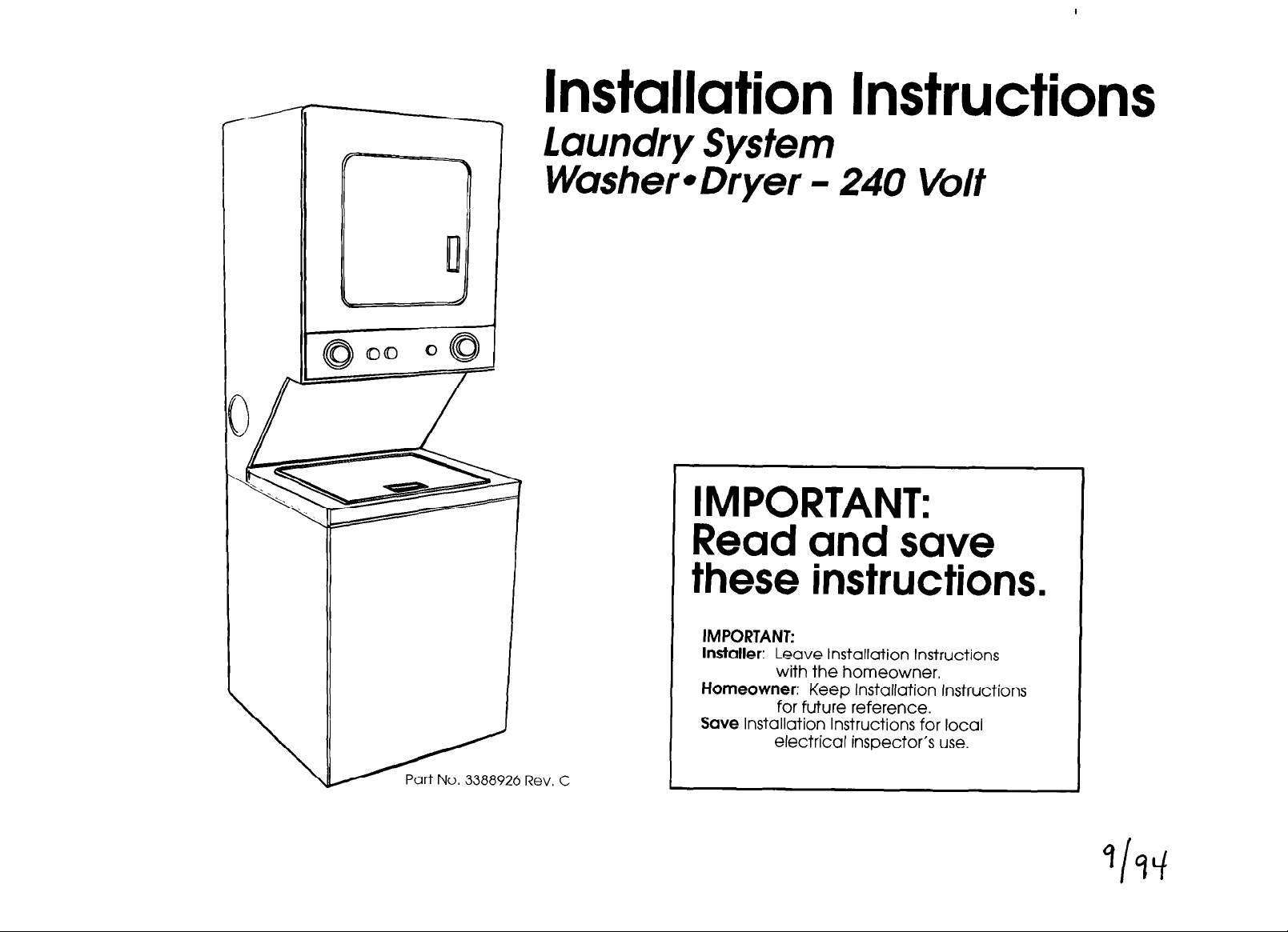
Installation Instructions
1 Laundry System
I
WushereDryer -
IMPORTANT:
Read and save
these instructions.
IMPORTANT:
Installer: Leave Installation Instructions
with the homeowner.
Homeowner: Keep Installation instructions
for future reference.
Save Installation Instructions for local
electrical inspector’s use.
240 Volt
Page 2
I
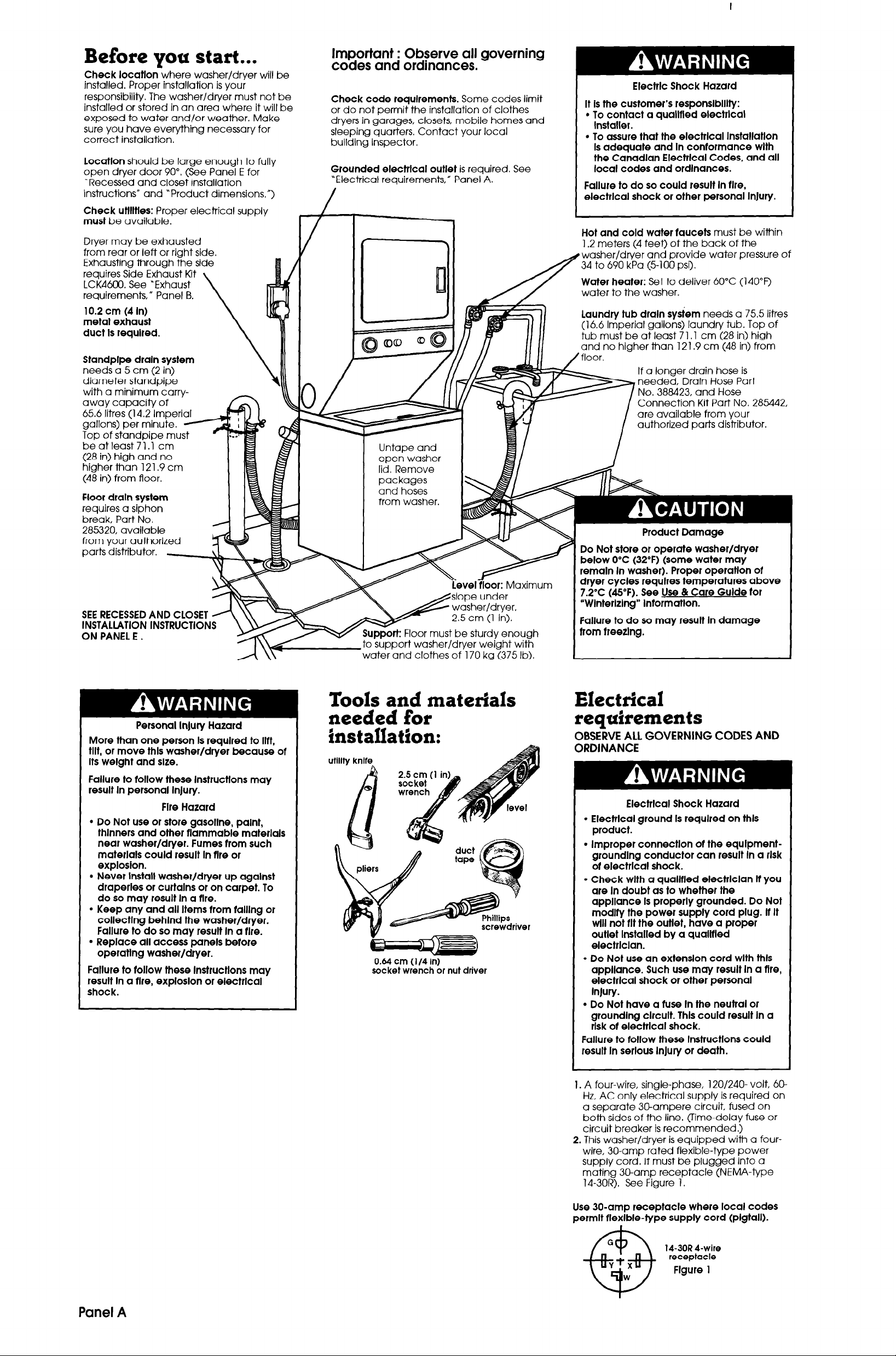
Before you start...
Check locatlon
installed. Proper installation is your
responsibility. The washer/dryer must not be
installed or stored in an area where it will be
exposed to water and/or weather. Make
sure you have everything necessary for
correct installation.
Location
open dryer door 90”. (See Panel E for
‘Recessed and closet installation
instructions” and “Product dimensions,“)
should be large enough to fully
Check utllltles:
must
be available.
Dryer may be exhausted
from rear or left or right side.
Exhausting through the side
requires Side Exhaust Kit
LCK4600. See “Exhaust
requirements, ti Panel B.
10.2 cm (4 In)
metal exhaust
duct Is required.
Standplpe draln system
needs a 5 cm (2 in)
diameter standpipe
with a minimum carry-
away capaclry or
65.6 litres (14.2 Imperiafi)
gallons) per minute.
Top of standpipe
beatleast71.1 cm
(28 in) high and no
higher than 121.9 cm
(48 in) from floor.
where washer/dryer will be
Proper electrical supply
\
_ n
Important : Observe all governing
codes and ordinances.
Check code requirements.
or do not permit the installation of clothes
dryers in garages, closets, mobile homes and
sleeping quarters. Contact your local
building inspector.
Grounded electrlcal outlet
“Electrical requirements,” Panel A.
I-
f
Some codes limit
is required. See
I
Electric Shock Hazard
It Is the customer’s responslblllty:
l
To contact a quallfled electrlcal
Installer.
. To assure that the electrlcal InstallatlOn
Is adequate and In conformance wlth
the Canadlan Electrlcal Codes, and all
local codes and ordinances.
Failure to do so could result In flre,
electrlcal shock or other personal InJury.
Hot and cold water faucets
1.2 meters (4 feet) of the back of the
washer/dryer and provide water pressure of
34 to 690 kPa (5-100 psi).
Water heater:
water to the washer.
Set to deliver 60°C (140°F)
Laundry tub drain sysiem
(16.6 Imperial gallons) laundry tub. Top of
tub must be at least 71 .l cm (28 in) high
no higher than 121.9 cm (48 in) from
If a longer drain hose is
needed, Drain Hose Part
No. 388423, and Hose
Connection Kit Part No. 285442,
are available from your
authorized parts distributor.
must be within
needs a 75.5 litres
Floor drain system
requires a siphon
break, Part No.
285320, available
from your authorized
parts distributor.
I \-
Personal Injury Hazard
More than one person Is required to Ilft.
tilt, or move thls washer/dryer because of
Its weight and size.
Failure to follow these lnstructlons may
result In personal InJury.
Fire Hazard
l
Do Not use or store gasoline, palnt,
thlnners and other flammable materials
near washer/dryer. Fumes from such
materials could result In flre or
explosion.
l
Never Install washer/dryer up agalnst
draperies or curtains or on carpet. To
do so may result In a fire.
l
Keep any and all Items from klllng or
collecting behlnd the washer/dryer.
Failure to do so may result In a fire.
l
Replace all access panels before
operatlng washer/dryer.
Failure to follow these lnstructlons may
result In a fire, exploslon or electrlcal
shock.
.- -..pport washer/dryer weight wifi
water and clothes of 170 kg (375 lb).
Tools and materials
needed for
installation:
0.64 cm (l/4
socket wrench or nut
in)
driver
Product Damage
Do Not store or operate washer/dryer
below 0°C (32°F) (some water may
remaln In washer). Proper operatlon of
dryer cycles requires temperatures above
7.2% (45°F). See Use & Care Guide for
“Wlnterlzlng” InformatIon.
Failure to do so may result In damage
from freezlng.
Electrical requirements
OBSERVE ALL GOVERNING CODES AND
ORDINANCE
Electrlcal Shock Hazard
. Electrlcal ground Is required on thls
product.
l
Improper connectlon of the equlpmentgroundlng conductor can result In a rlsk
of electrlcal shock.
l
Check wlth a quallfled electrlclan If you
are In doubt as to whether the
appliance Is properly grounded. Do Not
modify the power supply cord plug. If It
will not flt the outlet, have a proper
outlet Installed by a quallfled
electrlclan.
l
Do Not use an extension cord wlth thls
appliance. Such use may result In a fire,
electrlcal shock or other personal
InJury.
l
Do Not have a fuse In the neutral or
grounding clrcult. Thls could result In a
rlsk of electrlcal shock.
Failure to follow these lnstructlons could
result In serlous InJury or death.
Panel A
1.
A four-wire, single-phase, 120/240- volt, 60-
Hz, AC only electrical supply is required on
a separate 3(lampere circuit, fused on
both sides of the line. (Time-delay fuse or
circuit breaker is recommended.)
2. This washer/dryer is equipped with a fourwire, 30-amp rated flexible-type power
supply cord. It must be plugged into a
mating 30-amp receptacle (NEMA-type
14-30R). See Figure 1.
Use 30-amp receptacle where local codes
permit flexible-type supply cord (pigtall).
14-30R I-wire
receptacle
Figure 1
Page 3
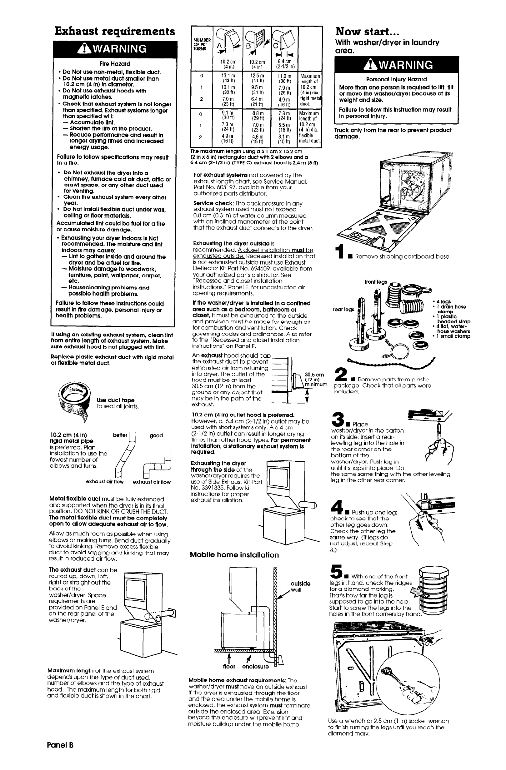
Exhaust reauirements
Fire Hazard
l
Do Not use non-metal, flexible duct.
l
Do Not use metal duct smaller than
10.2 cm (4 In) In diameter.
l
Do Not use exhaust hoods with
magnetic latches.
l
Check that exhaust system Is not longer
than speclfled. Exhaust systems longer
than speclfled will:
- Accumulate Ilnt.
- Shorten the II18 of the product.
- Reduce performance and result In
longer drying times and Increased
energy usage.
Failure to follow speclflcatlons may result
In a flre.
l
Do Not exhaust the dryer Into a
chimney, furnace cold alr duct, attlc or
crawl space, or any other duct used
for venting.
l
Clean the exhaust system every other
year.
l
Do Not Install flexible duct under wall,
celling or rloor materials.
Accumulated lint could be fuel for a flre
or cause moisture damage.
l
Exhausting your dryer Indoors Is Not
recommended. The moisture and lint
Indoors may cause:
- Lint to gather lnslde and around the
dryer and be a fuel for rlre.
- Moisture damage to woodwork,
furniture, paint, wallpaper, carpet,
etc.
- Housecleanlng problems and
posslble health problems.
Failure to follow these lnstructlons could
result In fire damage, personal InJury or
health problems.
If uslng an exlstlng exhaust system, clean lint
from entlre length of exhaust system. Make
sure exhaust hood Is not plugged with Ilnt.
Replace plastic exhaust duct with rlgld metal
or tlexlble metal duct.
Use duct tape
to seal all joints.
10.2 cm (4 in) better
rlgld metal pipe
is preferred. Plan
installation to use the
fewest number of
elbows and turns.
exhaust air flow
Metal rlexlble duct
and supported when the dryer is in its final
position. DO NOT KINK OR CRUSH THE DUCT.
&CA
must be fully extended
The metal flexible duct must be completely
open to allow adequate exhaust alr to flow.
Allow as much room as possible when using
elbows or making turns. Bend duct gradually
to avoid kinking. Remove excess flexible
duct to avoid sagging and kinking that may
result in reduced air flow.
good
exhaust air flow
NUMBER
OF 90”
TURNS
10.2 cm
(4
in)
13.1 m
(43 ft)
10.1 m
(33 ft)
7.0
m
(23
ft)
9.1 m
(30 w
7.3 m
(24 ft)
4.9
m
Wfi)
The maximum length using a 5.1 cm x 15.2 cm
(2 in x 6 in) rectangular duct with 2
6.4 cm Q-1/2 in) (TYPE C) exhaust hood is 2.4 m (8 ft).
For exhaust systems
exhaust length chart, see Service Manual,
Part No. 603197, available from your
authorized parts distributor.
Service check:
exhaust system used must not exceed
0.8 cm (0.3 in) of water column measured
with an inclined manometer at the point
that the exhaust duct connects to the dryer.
Exhausting the dryer outslde
recommended. A closet installation
exhausted outside. Recessed installation that
is not exhausted outside must use Exhaust
Deflector Kit Part No. 694609, available from
your authorized parts distributor. See
“Recessed and closet installation
instructions,” Panel E. for unobstructed air
opening requirements.
12.5 m 12.5
m
(41 fu (41 fu
9.5 m
(31 fv
6.4 m
(21
ft)
7.0 m
(23 fi)
4.6 m
(lsft)
not covered by the
The back pressure in any
11.0 m 11.0 m
(36 ft) (36 ft)
I
7.9 m
(26
4.9 m
(16ft)
5.5
U8fQ
3.1 m
(10 ft)
elbows
is
fi)
m
and a
must
Maximum
length of
10.2 cm
(4
in) dia.
rigid meta
duct.
ength of
10.2 cm
4 in) dia.
lexible
netal duct
be
If the washer/dryer Is Installed In a conflned
area such as a bedroom, bathroom or
closet,
and provision must be made for enough air
for combustion and ventilation. Check
governing codes and ordinances. Also refer
to the “Recessed and closet installation
instructions” on Panel E.
An
the exhaust duct to prevent
exhausted air from returning
into dryer. The outlet of the
hood must be at least
30.5 cm (12 in) from the
ground or any object that
may be in the path of the
exhaust.
it must be exhausted to the outside
exhaust
hood should cap
3%
30.5
cm
(12
in)
minimum
10.2 cm (4 In) outlet hood Is preferred.
However, a 6.4 cm (2-l /2 in) outlet may be
used with short systems only. A 6.4 cm
(2-l/2 in) outlet can result in longer drying
times than other hood types.
For permanent
Installation, a stationary exhaust system Is
required.
Exhaustlng the dryer
through the side
washer/dryer requires the
use of Side Exhaust Kit Part
No. 3391335. Follow kit
instructions for proper
exhaust installation.
of the
Mobile home installation
Now start...
With washer/dryer in laundry
area.
Personal Injury Hazard
More than one person Is required to Ilft, tilt
or move the washer/dryer because of Its
weight and size.
Failure to follow this InstructIon may result
In personal Injury.
Truck only from the rear to prevent product
damage.
n Remove shipping cardboard base.
l
4
legs
l
1 drain hose
clamp
l
1 plastic
beaded
l
4 flat,
hose washers
l
1 small
n Remove parts from plastic
package. Check that all parts were
included.
washer/dryer in the carton
on its side. Insert a rearleveling leg into the hole in
the rear corner on the
bottom of the
washer/dryer. Push leg in
until it snaps into place. Do
the same same thing with the other leveling
leg in the other rear corner.
4
n Push up one leg;
check to see that the
other leg goes down.
Check the other leg the
same way. (If legs do
not adjust, repeat Step
3.1
strap
water-
clamp
The exhaust duct
routed up, down, left,
right or straight out the
back of the
washer/dryer. Space
requirements are
provided on Panel E and
on the rear panel of the
washer/dryer.
Maxlmum length
depends upon the type of duct used,
number of elbows and the type of exhaust
hood. The maximum length for both rigid
and flexible duct is shown in the chart.
can be
of the exhaust system
Panel B
outslde
wall
I/
floor
Moblle home exhaust requirements:
washer/dryer
If the dryer is exhausted through the floor
and the area under the mobile home is
enclosed, the exhaust system
outside the enclosed area. Extension
beyond the enclosure will prevent lint and
moisture buildup under the mobile home.
must
have an outside exhaust.
must
The
terminate
n With one of the front
legs in hand, check the ridges
fo;a diamond marking. -
That’s how far the leg is
supposed to go into the hole.
Start to screw the legs into the
holes in the front corners by han
Jse a wrench or 2.5 cm (1 in) socket wrench
!o finish turning the legs until you reach the
diamond mark.
Page 4

Floor Damage
Slide dryer onto cardboard or hardboard
More movlng across floor.
Failure to do so may cause damage to
tloor coverlng.
H Now stand the washer/dryer up. Slide
6
washer/dryer onto cardboard or hardboard.
To prevent
product
damage, do
not remove
corner posts
betore
cutting.
Numbers
correspond
to steps.
8.
n
With the corner posts in place, CI
the carton down one corner. Remove
carton.
H Remove the
8
two rear corner posts
located at the back
of the washer/dryer.
Remove the two
corner pieces attached to
the lower front of the washer/dryer. Do
remove the foam shipping pieces between
the washer and dryer until the unit is in place.
Not
H Read the yellow
zGd;ace hand on top of
agitator when removing the
shipping straps. Firmly jerk,
then pull the three straps up
until each strap with key is
completely removed from
washer. Put straps in the
same area as rear corner
shipping pieces.
out of washer.
shippin
s strap WI
key
n
12
lid by pushing up on latch.
Close lid.
Use new hoses and washers that came
with your washer/dryer.
13
of the inlet hoses, Check that washers are
h
firmly seated in couplings.
Inlet valves are
plastic. Do Not
strip or
crossthread.
Release washer
coupling
n
Insert a flat washer into
washer
each
end
H Move
9
foam shipping
pieces outward just enough to clear the
washer lid. Open the washer lid. The latch
under the dryer will hold lid open,
11
yellow card. Take
hoses out of
basket. Place
hoses with other
parts,
Kl
14
- -~
inlet valve opening first. Attach second hose
to top inlet valve. Tighten couplings by hand;
then use pliers to make an additional twothirds turn.
IMPORTANT: THIS PROCEDURE MUST BE
FOLLOWED TO ASSURE PROPER
INSTALLATION.
15
coming off or leaking, it must be installed per
the following instructions:
1. Wet the inside end of the drain hose with
2. Squeeze ears of small clamp with pliers to
3. While holding clamp open, work end of
4. Position clamp over the drain hose area
I Attach hc
H To prevent the drain hose from
tap water.
LUBRICANT.
open clamp and place clamp over end
of drain hose.
drain hose onto drain connector until
drain hose is within 0.64 cm (l/4 in) of
ribbed stop.
marked “clamp.” Release clamp. Clamp
should be 0.64 cm (l/4 in) from end of
drain hose.
DO NOT USE ANY OTHER
xe to bottom
cm
in)
Panel C
Page 5

Numbers
correspond
to steps.
n
16
clamp and slide over “hook”
end of drain hose to secure
the rigid and corrugated
sections together.
Open hose
23.
22.
20.
Tilt the washer/dryer forward - raising back
legs 2.5 cm (1 in) off the floor to let the rear
self-leveling legs adjust. Gently lower the
washer/dryer to the floor. Make final check
with level.
Floor Damage
Slide washer/dryer onto cardboard or
hardboard before movlng across tloor.
Failure to do so may cause damage to
floor coverlng.
17
either side ot the washer/dryer,
washer/dryer close to final position so you
can easily complete the installation steps.
If you are worklng In a closet or recessed
area,
position and remove cardboard/hardboard
from under washer/dryer. Remove the two
Phillips-head screws located at the top of
the access panel. (See illustration for Step
23). Remove access panel and set access
panel and screws aside. Complete the
following steps through the access area.
18
hose in laundry tub or standpipe. Check for
proper length of drain hose.
DO NOT FORCE EXCESS LENGTH OF DRAIN
HOSE DOWN THE STANDPIPE. THIS COULD
CAUSE SIPHONING.
19
attaching water inlet
hoses, run water through
both faucets into a bucket.
This will get rid of any
particles in water lines that might clog hoses,
Mark which is the hot water faucet.
20
(inlet marked ‘H”) to hot water faucet.
Attach top hose (inlet marked ‘C”) to cold
water faucet. Tighten the couplings to the
faucets by hand. Use pliers to make the final
two-thirds turn.
Move washer/dryer to its permanent
position. Remove cardboard/hardboard
from under washer/
21
the levelness of
washer/dryer by
placing a carpenter’s
level on top of the washer,
first side to’side then front to back. If it is not
level, adjust the front legs up or down,
n It you have room to work tram
move
move the washer/dryer into its final
n
Put “hook” end of drain
n Before
n
Attach bottom hose
n
Check
Property Damage
Secure the draln hose to the tub or
standplpe wlth the plastic strap.
Failure to properly secure draln hose
could result In water damage.
plastic
beaded
strap
beaded strap
n
2
tub or standpipe. Wrap the plastic beaded
strap around the drain hose and tub or
standpipe. Thread beaded end of strap
through keyhole end. Pull until strap is tight.
Slide strap into narrow end of keyhole to lock
strap in place. See Figures A-B.
If the water inlet faucets and drain standpipe
are recessed, put ‘hook” end of drain hose in
standpipe. Tightly wrap the plastic beaded
strap around the drain hose and faucet body.
(Do
Not
or stems.) Thread beaded end of strap through
keyhole end. Pull until strap is tight. Slide strap
into narrow end of keyhole to lock strap in
place. See Figure C.
tf draln hose cannot be strapped Into place,
hose must be cut exactly to length so “hook”
end ls held tlghtly over edge of tub or
standplpe.
If a longer drain hose is
needed, Drain Hose Part No.
388423 and Hose Connection
Kit Part No. 28.5442 are
available from your authorted
parts distributor. If drain hose
must be shortened, use Hose
Connection Kit Part No. 285442.
Note: lt washer/dryer Is moved to adjust draln
hose, the washer/dryer must be leveled agaln.
Repeat Step 21. Place cardboard under the
washer/dryer and caretuliy move
washer/dryer to avold damaglng rloor
coverlng.
Put ‘hook” end of drain hose in
wrap strap around the faucet handles
n
23
pieces between the washer and dryer and place with the other shipping pieces. If the
exhaust duct cannot be connected from
the side of the washer/dryer, the exhaust
duct can be reached from the front through
the access panel. Remove the two Phillipshead screws at the top of the access panel.
Set access panel and screws aside.
24
exhaust duct that is needed to connect the
dryer to the exhaust hood. (See ‘Exhaust
requirements,” Panel B).
25
Connect
washer/dryer and then to the exhaust hood.
l
Use the straightest path possible to avoid
90” turns.
l
Use duct tape to seal
exhaust system.
l
Use caulking compound to seal exterior
wall opening around exhaust hood.
REQUIREMENTS. BE SURE YOU HAVE CORRECT
ELECTRICAL SUPPLY AND RECOMMENDED
GROUNDING METHOD.
Check the Installation Instructions to see that
you have completed each step. Complete
any missed steps before you continue.
27
Installed.
extra part, ao back through the steps to see
which stepwas skipped. -
Remove the two foam shipping
n
Determine the length of
-duct taD6
‘1
exhaust duct to
all
joints in the
n
Check that all parts are now
See parts list, Panel B. If there is an
Panel D
Page 6

Recessed and closet
Product dimensions
n
28
you removed all the
shipping pieces, including the
three shipping straps with keys.
Ir you do not remove all three shlpplng
straps, your washer/dryer may “walk” away
from Its locatlon.
Check that
1;11
nstallatlon
:nstructions
Fire Hazard
l
It Is recommended that the
washer/dryer be exhausted to the
outslde.
l
If washer/dryer Is Installed In a closet,
the dryer MUST be exhausted outslde.
Failure to do so may result In a tire.
To prevent large amounts ot llnt and molsture
trom accumulating and to malntaln drylng
etflclency, and to prevent exposure to
possible health hazards, thls appliance
should be exhausted outdoors.
THIS WASHER/DRYER MAY BE INSTALLED
IN A RECESSED AREA OR CLOSET.
The installation spacing is in inches and is the
minimum allowable.
Additional spacing should be considered for
ease of installation, servicing and
compliance with local codes and
ordinances.
If closet door is installed, the minimum
unobstructed air openings in top and
bottom are required. Louvered doors with
equivalent air openings are acceptable.
Closet installation must be exhausted.
Other installations must use the minimum
dimensions indicated.
Rear view
& 24” +
f
drain
27-l/2”
Side view
39 cm
m =.,cm
(21~5/16ln) j
4
\
n
29
your tools.
30
and check for leaks. Tighten couplings if
there is leaking.
31
into grounded outlet.
32
sure to tighten screws at each end of the
access panel.
33
to fully understand your new washer/dryer.
Now start the washer and allow it to
complete the regular cycle.
Check that you have all
n
Turn on water faucets
n
Plug power supply cord
n
Replace the access panel. E3e
n
Read the Use and Care Guide
Recessed installation
front view
w-w
Mlnlmum lnstallatlon spacing
Note:
If recessed installation is exhausted, all
spacing can be 0 cm (0 in).
Additional clearance for wall, door and floor
molding may be required.
side view
7.4 cm
(3 In) -D
Closet installation
front view
It
IA
-
309.7 tq.cm
(48 sq. In)
13.3 cm
-
a-
182.3 cm
(71-314 In)
t
82.6 cm
(32-l/2 In)
69.2 cm
(27-l/4 In) -
-5-l/4 In)
f
96je5 ly
L
H Remove tape from drver door
and open dryer door. Remove tape across
the dryer lint screen. Check to be sure lint
screen is in its proper position. Wipe out drum
with a damp cloth to remove any dust. Start
dryer and allow it to complete a heat cycle
to make sure the dryer is working properly.
35
keep with washer/dryer.
H Finally, save all literature and
/b!iJii!i!ik-J
To get the most efflclent use from
1 Congratulations! \
Keep lnstallatlon lnstructlons nearby
~~~~~~~
Tf
closet
L-
door
Unobstructed air openings are minimum for closet
door. Louvered door with equivalent air openings
is acceptable.
side view
309.7 sq. cm
(48 sq. In)
+I + 2.5 cm (1 In)
Closet installation must be exhausted outdoors.
Recessed, non-exhausted installation must use
only the rear exhaust position and Exhaust
Deflector Kit No. 4500 is required.
-4 +gnc;”
Additional
space may
be needed
fooywyaust
Panel E
Page 7

If
washer/dryer
does not operate...
l
Check that the circuit breaker is not
tripped or the house fuse blown.
l
Check that power supply cord is plugged
into wall receptacle.
Part No. 3388926 Rev. C
01994
Printed on recycled paper.
10% post consumer waste/
50% recovered materials.
lnglis Limited, 1901 Minnesota Court, Mississauga, Ontario L5N 3A7
Washers l Dryers l Refrigerators
l
Dishwashers l Waste Compactors l Microwave Ovens
BRANCHES ACROSS CANADA
Printed in U.S.A.
 Loading...