

Alliance Laundry Systems UWL045T3V, UWL065T4V, UWL065T3V, UWL045T4V, UWU045T3V Programming Manual
...Page 1

Washer-Extractor
PHM14
PHM1423C
Pocket Hardmount
UniLinc Control
Refer to Page 9 for Model Identification
Programming
Keep These Instructions for Future Reference.
(If this machine changes ownership, this manual must accompany machine.)
www.comlaundry.com
Part No. F8434101R1
April 2012
Page 2

Page 3

Table of
Contents
Safety Information.............................................................................. 5
Explanation of Safety Messages........................................................... 5
Important Safety Instructions ............................................................... 5
Safety Decals ........................................................................................ 7
Operator Safety..................................................................................... 8
Introduction......................................................................................... 9
Model Identification ............................................................................. 9
Nameplate Location.............................................................................. 10
Replacement Parts ................................................................................ 10
Customer Service.................................................................................. 10
Preliminary Information.................................................................... 11
About the Control ................................................................................. 11
Power Failure Recovery................................................................... 11
IR Communications ......................................................................... 11
Network Communications ............................................................... 11
Audit Information ........................................................................... 11
IR Communications Menu............................................................... 12
IR Communications Error Menu ..................................................... 12
Restore to Factory Defaults ............................................................ 12
Entering Program Mode................................................................... 13
UniLinc Identification ........................................................................ 14
Operational Keypad.............................................................................. 14
Operation Modes .................................................................................. 15
General Modes of Operation............................................................ 15
Power-up Mode................................................................................ 15
Idle Mode......................................................................................... 15
Door Locking Mode......................................................................... 15
Run Mode......................................................................................... 15
Stop Mode........................................................................................ 15
Door Unlocking Mode ..................................................................... 15
Error Mode....................................................................................... 15
Delayed Start Countdown Mode...................................................... 15
Communication Mode ..................................................................... 15
Entering Diagnostic Mode From Idle Mode.................................... 15
© Copyright 2012, Alliance Laundry Systems LLC
All rights reserved. No part of the contents of this book may be reproduced or transmitted in any form or by any
means without the expressed written consent of the publisher.
F8434101
© Copyright, Alliance Laundry Systems LLC – DO NOT COPY or TRANSMIT
Machine Cycle Definition and Operation......................................... 16
Machine Cycle Operation..................................................................... 16
Delayed Start Feature ........................................................................... 16
Cycle Menu........................................................................................... 16
To Start a Cycle ............................................................................... 17
Run Menu ............................................................................................. 18
Contrast/Backlight Menu...................................................................... 20
Close Door Menu.................................................................................. 20
Lubricate Bearings Menu ..................................................................... 21
Run Diagnostic Menu........................................................................... 21
Speed, Temp and Water Level Menu ................................................... 22
Cycle Aborted Retry Menu................................................................... 22
Cycle Aborted Fatal Menu.................................................................... 23
1
Page 4

Error Menu............................................................................................ 23
Cycle Stopped Menu............................................................................. 23
Delayed Start Menu .............................................................................. 23
Delayed Start Countdown Menu .......................................................... 24
Delayed Start Final Countdown Menu ................................................. 24
Menu Navigation................................................................................. 25
The UniLinc.......................................................................................... 25
Menu Navigation on a Single Screen ................................................... 25
Menu Navigation with Parameters ....................................................... 25
Screen to Screen Navigation using the Arrow Keypads....................... 25
Navigation in String Edit Mode............................................................ 25
Display Screen Maps ............................................................................ 26
System Menu Map Tree................................................................... 26
Run Menu Map Tree........................................................................ 27
Service Menu Map Tree................................................................... 27
Programming UniLinc ....................................................................... 28
System Menu ........................................................................................ 28
Save Changes Menu ............................................................................. 28
Program Menu .................................................................................... 29
Program Menu ...................................................................................... 29
Modify Cycle........................................................................................ 29
Available Characters........................................................................ 30
Cycle, Segment and Step Programming Flow Diagram....................... 31
Step Menu Navigation ..................................................................... 31
Reuse Fill Step Menu....................................................................... 32
Fill Step Menu.................................................................................. 33
Heater Option................................................................................... 34
Supply A and B Step Menu ............................................................ 34
Agitate Step Menu ........................................................................... 35
Cool Down Step Menu..................................................................... 35
Drain Step Menu ............................................................................. 36
Spray Rinse Extract Step Menu ....................................................... 36
Extract Step Menu............................................................................ 37
General Purpose Signals Menu........................................................ 37
End of Segment Audio Signal Step Menu ....................................... 38
Global Setup ........................................................................................ 39
Global Setup Menu............................................................................... 39
Language Menu .................................................................................... 39
Date/Time Menu................................................................................... 39
Water Level Menu ................................................................................ 40
Temperature Menu................................................................................ 40
Audio Menu.......................................................................................... 41
Balance Retry Menu ............................................................................. 41
Water Management Menu .................................................................... 42
Alarms Program Menu ......................................................................... 44
Rapid Advance Menu ........................................................................... 44
Shakeout Menu..................................................................................... 45
2
© Copyright, Alliance Laundry Systems LLC – DO NOT COPY or TRANSMIT
F8434101
Page 5

Banners Menu....................................................................................... 45
Factory Defaults Menu ......................................................................... 45
Water Level Confirmation Menu.......................................................... 46
Water Temperature Confirmation Menu .............................................. 46
Alarms Confirmation Menu.................................................................. 46
Audio Confirmation Menu ................................................................... 47
Reset All Factory Defaults Confirmation Menu................................... 47
Factory Defaults Second Confirmation Menu...................................... 47
Diagnostic ............................................................................................ 48
Diagnostic Menu................................................................................... 48
Drive ID Menu................................................................................. 48
Drive Alarms Menu ......................................................................... 48
Test Menu ............................................................................................. 48
Test Cycle ........................................................................................ 49
Factory Valve Purge Menu................................................................... 51
Inputs Outputs Menu ............................................................................ 51
Water Leak Detection Diagnostic......................................................... 53
Drive Test ............................................................................................. 53
Alarms................................................................................................... 54
Machine Identification.......................................................................... 55
Machine Errors ..................................................................................... 55
Door Lock Error .............................................................................. 55
Door Open Error ............................................................................. 55
Drain Alarm Error ........................................................................... 55
Fill Alarm Error ............................................................................... 55
Frame Balance Switch Error............................................................ 56
Open Temperature Sensor Error ..................................................... 56
Shorted Temperature Sensor Error ................................................. 56
SPI Error .......................................................................................... 56
Unbalance Error............................................................................... 56
Heat Alarm Error ............................................................................. 56
Water Level Sensor Error ................................................................ 57
IR Communications Error................................................................ 57
Network Communications Error...................................................... 57
Water Leak Detection Error............................................................. 57
Slow Drain Detected During A Machine Cycle Error..................... 58
Drive SPI Error ................................................................................ 58
DC Bus Error ................................................................................... 58
No Tachometer Error ....................................................................... 58
Locked Rotor Error.......................................................................... 58
Shorted IGBT Error ......................................................................... 58
IPM Overtemperature Error............................................................. 59
Invalid Parameter Set Error ............................................................. 59
Maximum Current Exceeded Error.................................................. 59
Current Sensor Error........................................................................ 59
Low DC Bus Error........................................................................... 59
Invalid Command Error ................................................................... 59
Last Drive Error ............................................................................... 59
F8434101
© Copyright, Alliance Laundry Systems LLC – DO NOT COPY or TRANSMIT
3
Page 6

Laundry Management........................................................................ 60
Total Number of Machine Cycle Counters........................................... 61
Total Number of Operating Minutes Counters..................................... 61
Last 10 Machine Cycles Rapid Advanced or Stopped ......................... 61
Maintenance ........................................................................................ 62
Service Schedule Menu ........................................................................ 62
Daily Menu (Service)....................................................................... 62
Weekly Menu (Service) ................................................................... 62
Monthly Menu (Service).................................................................. 63
Quarterly Menu (Service) ................................................................ 63
Cycle Charts ........................................................................................ 64
4
© Copyright, Alliance Laundry Systems LLC – DO NOT COPY or TRANSMIT
F8434101
Page 7

Safety Information
DANGER indicates the presence of a
hazard that will cause severe personal
injury, death, or substantial property
damage if the danger is ignored.
DANGER
WARNING indicates the presence of a
hazard that can cause severe personal
injury, death, or substantial property
damage if the warning is ignored.
WARNING
CAUTION indicates the presence of a
hazard that will or can cause minor
personal injury or property damage if the
caution is ignored.
CAUTION
To reduce the risk of fire, electric shock,
serious injury or death to persons when
using your washer, follow these basic
precautions:
W023
WARNING
Explanation of Safety Messages
Precautionary statements (“DANGER,” “WARNING,”
and “CAUTION”), followed by specific instructions,
are found in this manual and on machine decals. These
precautions are intended for the personal safety of the
operator, user, servicer, and those maintaining the
machine.
Additional precautionary statements (“IMPORTANT”
and “NOTE”) are followed by specific instructions.
IMPORTANT: The word “IMPORTANT” is used
to inform the reader of specific procedures where
minor machine damage will occur if the procedure
is not followed.
NOTE: The word “NOTE” is used to communicate
installation, operation, maintenance or servicing
information that is important but not hazard
related.
Important Safety Instructions
1. Read all instructions before using the washer.
2. GInstall the washer according the
INSTALLATION instructions. Refer to the
GROUNDING instructions in the
INSTALLATION manual for the proper
grounding of the washer. All connections for
water, drain, electrical power and grounding must
comply with local codes and be made by licensed
personnel when required. It is recommended that
the machine be installed by qualified technicians.
3. Do not install or store the washer where it will be
exposed to water and/or weather.
4. To prevent fire and explosion, keep the area
around machine free from flammable and
combustible products. Do not add the following
substances or textiles containing traces of the
following substances to the wash water: gasoline,
kerosene, waxes, cooking oils, vegetable oils,
machine oils, dry-cleaning solvents, flammable
chemicals, thinners, or other flammable or
explosive substances. These substances give off
vapors that could ignite, explode or cause the
fabric to catch fire by itself.
5. Under certain conditions, hydrogen gas may be
produced in a hot water system that has not been
used for two weeks or more. HYDROGEN GAS
IS EXPLOSIVE. If the hot water system has not
been used for such a period, before using a
washing machine or combination washer-dryer,
turn on all hot water faucets and let the water
flow from each for several minutes. This will
release any accumulated hydrogen gas. The gas
is flammable, do not smoke or use an open flame
during this time.
F8434101
© Copyright, Alliance Laundry Systems LLC – DO NOT COPY or TRANSMIT
6. To reduce the risk of an electric shock or fire, DO
NOT use an extension cord or an adapter to
connect the washer to the electrical power
source.
5
Page 8

Safety Information
7. Do not allow children to play on or in the washer.
Close supervision of children is necessary when
the washer is used near children. This appliance
is not intended for use by young children or
infirm persons without supervision. Young
children should be supervised to ensure that they
do not play with the appliance. This is a safety
rule for all appliances.
8. DO NOT reach and/or climb into the tub or onto
the washer, ESPECIALLY if the wash drum is
moving. This is an imminently hazardous
situation that, if not avoided, will cause severe
personal injury or death.
9. Never operate the washer with any guards, panels
and/or parts removed or broken. DO NOT bypass
any safety devices or tamper with the controls.
10. Use washer only for its intended purpose,
washing textiles. Never wash machine parts or
automotive parts in the machine. This could
result in serious damage to the basket or tub.
11. Use only low-sudsing, no-foaming types of
commercial detergent. Be aware that hazardous
chemicals may be present. Wear hand and eye
protection when adding detergents and
chemicals. Always read and follow
manufacturer’s instructions on packages of
laundry and cleaning aids. Heed all warnings or
precautions. To reduce the risk of poisoning or
chemical burns, keep them out of the reach of
children at all times (preferably in a locked
cabinet).
12. Do not use fabric softeners or products to
eliminate static unless recommended by the
manufacturer of the fabric softener or product.
13. Always follow the fabric care instructions
supplied by the textile manufacturer.
14. Loading door MUST BE CLOSED any time the
washer is to fill, tumble or spin. DO NOT bypass
the loading door switch by permitting the washer
to operate with the loading door open. Do not
attempt to open the door until the washer has
drained and all moving parts have stopped.
15. Be aware that hot water is used to flush the
supply dispenser. Avoid opening the dispenser
lid while the machine is running.
16. Do not attach anything to the supply dispenser’s
nozzles, if applicable. The air gap must be
maintained.
18. Be sure water connections have a shut-off valve
and that fill hose connections are tight. CLOSE
the shut-off valves at the end of each wash day.
19. Keep washer in good condition. Bumping or
dropping the washer can damage safety features.
If this occurs, have washer checked by a
qualified service person.
20. DANGER: Before inspecting or servicing
machine, power supply must be turned OFF. The
servicer needs to wait for at least 3 minutes after
turning the power OFF and needs to check for
residual voltage with a voltage meter. The
inverter capacitor or EMC filter remains charged
with high voltage for some time after powering
OFF. This is an imminently hazardous situation
that, if not avoided, will cause severe personal
injury or death.
21. Do not repair or replace any part of the washer, or
attempt any servicing unless specifically
recommended in the user-maintenance
instructions or in published user-repair
instructions that the user understands and has the
skills to carry out. ALWAYS disconnect the
washer from electrical, power and water supplies
before attempting any service.
22. Disconnect the power cord by grasping the plug,
not the cord. Replace worn power cords and/or
loose plugs. If the supply cord is damaged, it
must be replaced by a special cord or assembly
available from the service agent.
23. Before the washer is removed from service or
discarded, remove the door to the washing
compartment.
24. Failure to install, maintain, and/or operate this
washer according to the manufacturer’s
instructions may result in conditions which can
produce bodily injury and/or property damage.
NOTE: The WARNINGS and IMPORTANT
SAFETY INSTRUCTIONS appearing in this
manual are not meant to cover all possible
conditions and situations that may occur. Common
sense, caution and care must be exercised when
installing, maintaining, or operating the washer.
Any problems or conditions not understood should be
reported to the dealer, distributor, service agent or the
manufacturer.
17. Do not operate the machine without the water
reuse plug or water reuse system in place, if
applicable.
6
© Copyright, Alliance Laundry Systems LLC – DO NOT COPY or TRANSMIT
F8434101
Page 9

Safety Information
This machine must be installed, adjusted,
and serviced by qualified electrical
maintenance personnel familiar with the
construction and operation of this type of
machinery. They must also be familiar
with the potential hazards involved.
Failure to observe this warning may result
in personal injury and/or equipment
damage, and may void the warranty.
SW004
WARNING
Ensure that the machine is installed on a
level floor of sufficient strength and that
the recommended clearances for
inspection and maintenance are provided.
Never allow the inspection and
maintenance space to be blocked.
SW020
CAUTION
Be careful around the open door,
particularly when loading from a level
below the door. Impact with door edges
can cause personal injury.
SW025
Never touch internal or external steam
pipes, connections, or components.
These surfaces can be extremely hot and
will cause severe burns. The steam must
be turned off and the pipe, connections,
and components allowed to cool before
the pipe can be touched.
SW014
WARNING
Safety Decals
Safety decals appear at crucial locations on the
machine. Failure to maintain legible safety decals
could result in injury to the operator or service
technician.
Use manufacturer-authorized spare parts to avoid
safety hazards.
CAUTION
F8434101
© Copyright, Alliance Laundry Systems LLC – DO NOT COPY or TRANSMIT
7
Page 10

Safety Information
NEVER insert hands or objects into
basket until it has completely stopped.
Doing so could result in serious injury.
SW012
WARNING
Operating the machine with severe out-ofbalance loads could result in personal
injury and serious equipment damage.
W728
WARNING
Operator Safety
The following maintenance checks must be performed
daily:
1. Verify that all warning signs are present and
legible, replace as necessary.
2. Check door interlock before starting operation of
the machine:
a. Attempt to start the machine with the door
open. The machine should not start.
b. Close the door without locking it and start the
machine. The machine should not start.
c. Attempt to open the door while a cycle is in
progress. The door should not open.
If the door lock and interlock are not functioning
properly, disconnect power and call a service
technician.
NOTE: All information, illustrations, and
specifications contained in this manual are based
on the latest product information available at the
time of printing. We reserve the right to make
changes at any time without notice.
3. Do not attempt to operate the machine if any of
the following conditions are present:
a. The door does not remain securely locked
during the entire cycle.
b. Excessively high water level is evident.
c. Machine is not connected to a properly
grounded circuit.
Do not bypass any safety devices in the machine.
8
© Copyright, Alliance Laundry Systems LLC – DO NOT COPY or TRANSMIT
F8434101
Page 11

Introduction
Model Identification
Information in this manual is applicable to these
models:
UWL045T3V UWN065T4L
UWL045T4V UWN065T4M
UWL065T3V UWU045T3V
UWL065T4V UWU045T4V
UWN045T3V UWU065T3L
UWN045T4V UWU065T3M
UWN065T4V UWU065T3V
UWN065T3L UWU065T4L
UWN065T3M UWU065T4M
UWN065T3V UWU065T4V
F8434101
© Copyright, Alliance Laundry Systems LLC – DO NOT COPY or TRANSMIT
9
Page 12

Introduction
PHM847N
2
1
EXAMPLE OF MACHINE NAMEPLATE LOCATION
Nameplate Location
The nameplate is located on the back of the machine
and is programmed in the UniLinc Control. To access
Machine ID through the control:
1. Press and hold , then , then
keypads at the same time.
2. Press the keypad until Diagnostic is
highlighted.
3. Press the keypad.
4. Press the keypad until Machine ID is
highlighted.
5. Press the keypad.
Always provide the machine’s serial number and
model number when ordering parts or when seeking
technical assistance. Refer to Figure 1.
Replacement Parts
If literature or replacement parts are required, contact
the source from which the machine was purchased or
contact Alliance Laundry Systems LLC at
+1 920) 748-3950 for the name of the nearest
authorized parts distributor. A parts manual may be
ordered by returning the reply card provided with each
machine.
Customer Service
For technical assistance, contact your local distributor
or call:
Alliance Laundry Systems
Shepard Street
P. O . B o x 9 9 0
Ripon, WI 54971-0990
U.S.A.
www.comlaundry.com
Phone: +1 (920) 748-3121
1 In UniLinc Control
2 At back of machine
Figure 1
Ripon, Wisconsin
Alliance International
+3256412054
Wevelgem, Belgium
PHM847N
10
© Copyright, Alliance Laundry Systems LLC – DO NOT COPY or TRANSMIT
F8434101
Page 13

Preliminary Information
About the Control
The UniLinc control on the machine is an advanced,
graphical, programmable computer that lets the owner
control most machine features by interacting with the
control.
UniLinc allows the owner to program custom cycles,
run diagnostic cycles and retrieve audit, error and
bearing information.
Machines shipped from the factory have default cycles
and wash temperature settings built in. The owner can
change the default cycles or any cycle.
IMPORTANT: It is extremely important that the
machine has a positive ground and that all
mechanical and electrical connections are made
before applying power to or operating the machine.
Power Failure Recovery
If a cycle is in progress when the power fails, and if
the power outage lasts three or more seconds, the cycle
is lost and cannot be resumed when power recovers. If
the power outage lasts less than three seconds, the
control will resume the cycle when the power
recovers.
IR Communications
Audit Information
The control collects and stores audit information,
which can be accessed with a PC/PDA or through the
network. Refer to the following list for available audit
information.
• Total Number of Individual Cycle Counters
• Last 25 Machine Cycles
• Service History
• Machine Errors Audit Data
• Communication Audit Data
• Re-Programming Audit Data
• Power Failures Audit Data
• Average Fill Time Audit Data
• Average Drain Time Audit Data
• Power Failure Audit Data
The PC/PDA or the network can receive audit and
program data from the control, and send programming
data and diagnostic commands to the control.
Refer to UniLinc PC and PDA Application User
Instructions for additional information on using a PC/
PDA.
The control has the ability to communicate with a
PDA or PC with an IrDA device running the UniLinc
software. Devices such as PDAs and PCs that are
IrDA capable (able to transmit information to
machine) that have been tested and approved for use
with the UniLinc software can be used as a tool for
managing the machine.
Network Communications
The control has the ability to communicate through a
network. The network link allows the user to program,
collect data, and run diagnostics on any machine in the
network from a central location.
F8434101
© Copyright, Alliance Laundry Systems LLC – DO NOT COPY or TRANSMIT
11
Page 14

Preliminary Information
Invalid Data
IR Communications Menu
PHM1003R
Figure 2
The IR Communications Menu displays while the
control is communicating with a PC/PDA. The control
will jump back to the previous page when the
communication is complete.
IR Communications Error Menu
Restore to Factory Defaults
When the user selects Restore All Cycles And Global
Settings To Factory-Defaults, the control resets all of
the default values. The control also resets Machine
Cycles #1 through #41. The control will also reset the
following to factory defaults:
Default Machine Settings
Language = English
Maximum Balance Retries = 3
Water Reuse = Disabled
Rapid Advance = Enabled
Water Recirculation = Disabled
External Dispenser Pause = Disabled
Shakeout = 40 seconds
Banner # 1 = Blank
Banner # 2 = Blank
Daylight Saving = Enabled
Water Levels
PHM1004N
Figure 3
The IR Communications Error Menu displays after the
control had an error communicating with a PC/PDA.
The control will return to previous page after 3
seconds.
High = 27
Medium = 15
Low = 3
Water Temperature
Hot = 140 F
Warm = 100 F
Cold = 35 F
Cooldown = 110 F
Temperature Controlled Fill = Disabled
Audio Signal External Signal = Disabled
Keypad Signal (beep) = Enabled
Alarms
Fill = 5 minutes
Drain = 2 minutes
Heat = 1 hour 30 minutes
End of Segment / Cycle Sound = Enabled Low, 5
second duration
Advanced Options for Water Management = Disabled
Water Leak Detection During Machine Cycle =
Disabled
12
© Copyright, Alliance Laundry Systems LLC – DO NOT COPY or TRANSMIT
Number of Cycles Between = 0
Day(s) Occuring = none
F8434101
Page 15

Preliminary Information
Slow Drain Detection During Machine Cycle =
Disabled
Slow Drain Adjustment = 0 seconds
Auto-Water Leak Detection = Disabled
Number of Cycles Between = 0
Hours Occuring = 0 (12:00 AM)
Days(s) Occuring = none
Manual Programming = Enabled*
Manual Diagnostics = Enabled*
*If manual programming is disabled, programming
changes to UniLinc can only be made with an external
communication device. Refer to UniLinc PC and
PDA Applications User Instructions.
Refer to Factory Defaults, Menu section for
information on Restoring Factory Defaults.
Entering Program Mode
1. Press and hold , then , then to
enter the System Menu. Select Program to enter
programming options.
F8434101
© Copyright, Alliance Laundry Systems LLC – DO NOT COPY or TRANSMIT
13
Page 16

UniLinc Identification
Operational Keypad
The control includes seven keypads. These functions
are available to the operator and are intended to
control and manage operation of the machine. Refer to
Figure 4 and Tab le 1 .
PHM1423C
Figure 4
Keypad Description
LCD/UP ARROW
DOWN ARROW
LEFT ARROW
BACK
RIGHT ARROW
STOP/ON/OFF
START/ENTER
Press to move the cursor on display to edit programming values. Also, press
while in Cycle Menu or Run Menu to change to the
Menu. Also, press with and to enter System Menu.
Press to move the cursor on display or edit programming values.
Press to move cursor on display.
Press to move back to the previous display menu. Also, press with and
to enter System Menu. Also, back from the Cycle Menu to enter the
Service Schedule Menu.
Press to move cursor on display. Press while running a cycle to get to Run
Diagnostic Menu. Press and hold with to enter Delayed Start Menu.
Press to stop and abort a machine cycle during Run Mode. Also press with
and to enter System Menu. Press with to enter Delayed Start
Menu.
Press to start or rapid advance a machine cycle during Run Mode. Also, press to
save edited programming values when used in programming menus.
Tab le 1
Contrast Adjust/Backlight
14
© Copyright, Alliance Laundry Systems LLC – DO NOT COPY or TRANSMIT
F8434101
Page 17

UniLinc Identification
Operation Modes
General Modes of Operation
In each mode of operation, the user may press keypads
or communicate with the control to change the
displayed menu.
Power-up Mode
The control enters this mode at power-up. After the
control completes operation in the Power-up Mode it
will enter Idle Mode. The display is blank during
Power-up Mode.
Idle Mode
Control is ready for operation in Idle Mode. Control
can display different menus depending on user input
(keypad press, opening or closing the loading door, or
PC/PDA or network communication). If there is no
user input for one minute, control will turn off the
LCD backlight. Control will light when there is user
input. If there is no user input for 10 minutes, display
will go blank.
If control is in Idle Mode, Cycle Menu is displayed,
loading door closed, and the keypad is pressed,
control will enter Door Locking Mode.
Door Locking Mode
Stop Mode
If keypad is pressed before cycle ends, control
enters Stop Mode and performs the following steps:
• Displays a hourglass.
• Turns off all outputs.
• Verifies water is drained.
• Verifies motor is stopped by either rotation
sensor or time.
• Enters Door Unlocking Mode.
Door Unlocking Mode
The control enters this mode after cycle has ended.
The control waits for confirmation that door is
unlocked. Once confirmation is received that door is
unlocked, control will enter Idle Mode.
Error Mode
This mode will be entered to display all alarms and
machine errors.
Delayed Start Countdown Mode
Delayed Start Countdown Menu is entered after
delayed start is activated. The display will show the
hours and minutes remaining until the machine will
automatically start.
The control enters this mode after the keypad is
pressed in Idle Mode. The control will stay in the Door
Locking Mode until it confirms the loading door is
closed and locked. The control will enter Run Mode.
Run Mode
Control enters Run Mode during a cycle. Display
shows machine cycle time remaining, the colon
flashing one second on/one second off indicating that
the cycle time is counting down, and the display will
indicate the current cycle step. Loading door is closed
and locked during Run Mode. Press keypad to
end cycle and enter Stop Mode. Press keypad to
Rapid Advance to the next cycle step (if the Rapid
Advance feature is enabled. The Rapid Advance
feature is enabled by default.) Control enters Error
Mode if loading door unlocks or opens.
The Delayed Start Final Countdown Menu is entered
during the last sixty seconds before the control is
automatically started. The keypad will start the
selected cycle immediately. Press to return to the
Cycle Menu.
Communication Mode
This mode is entered whenever the control is
communicating with a PC/PDA or through the
network.
Refer to UniLinc PC and PDA Applications User
Instructions.
Entering Diagnostic Mode From Idle Mode
When entered from the Idle Mode, the control will be
running a test selected by the user via keypad presses
or communication with a device. The diagnostic tests
available from the Idle Mode are the Test Cycle, Test
Balance Weight, and Inputs Outputs Menus.
F8434101
© Copyright, Alliance Laundry Systems LLC – DO NOT COPY or TRANSMIT
15
Page 18

Machine Cycle Definition and Operation
For Technical Service
Distributor ABC
1-800-555-5555
Cycle41:
Supply Set
Up
Cycle02:
Towels White
Cycle01:
Towels
White
Bleach
Cycle Menu
There are 41 machine cycles which can be selected
and run. Machine cycles can be modified or made
“unavailable” by manually editing them in Modify
Cycle Menu or by using the PC/PDA or the network to
download a modified machine cycle into the control.
Machine cycles cannot be deleted, but can be made
“unavailable” so that they are not visible from the
Cycle Menu. New machine cycles cannot be created,
but existing machine cycles that have been edited to be
“unavailable” may be re-edited to be available again.
Machine Cycle Operation
When a cycle is run, the control runs the cycle
segment by segment and step by step in a sequence.
The first segment can be programmed to “Off”,
“Prewash”, “Wash” or “Rinse”. If the segment is
programmed to “Off”, control skips to the next
segment. If the segment is not programmed to “Off”,
the first segment step (Reuse Fill step) is examined to
see if it is programmed on. If the segment step is
programmed on, it is executed and the next step
follows until the segment is complete. Any segment
steps programmed to “Off” are skipped.
At the start of a machine cycle, the control displays a
Total Remaining Cycle time. This time is taken from
the audit data for this cycle where there is stored an
average time elapsed for the last three of these cycles
that had been completed. The Total Remaining Cycle
Time begins to count down as soon as the cycle is
started. Since there will be differences between the
average elapsed cycle time and the actual elapsed
cycle time, the Total Remaining Cycle Time displayed
is corrected at the start of the cycle’s final enabled step
that has programmed time duration.
Delayed Start Feature
The user can select a machine cycle to run at a later
time. Refer to Delayed Start Menu Section.
Cycle Menu
PHM702N
Figure 5
The Cycle Menu is the first menu displayed by the
control at power-up. The Cycle Menu allows the user
to select one of the 41 machine cycles. Machine cycles
that are turned off will not be displayed in the Cycle
Menu. As a default, the last run cycle will be displayed
in the center, highlighted position. The factory default
cycle will be Cycle01.
16
© Copyright, Alliance Laundry Systems LLC – DO NOT COPY or TRANSMIT
F8434101
Page 19

Machine Cycle Definition and Operation
To Start a Cycle
1. Press the or keypad to change cycles.
2. Press the keypad to move the cycle in the
rightmost menu box to the center, highlighted
position.
3. Press the keypad to move the cycle in the
leftmost menu box to the center, highlighted
position.
4. Moving the and keypads allows the
Cycle Menu to scroll through the center,
highlighted position.
5. Press to start selected cycle.
NOTE: Press and hold or keypad to
make highlighted area move rapidly.
NOTE: If door is not closed when the keypad
is pressed, display will jump to the Close Door
Menu.
NOTE: If the machine has operated over 200 hours
and the Lubricate Bearings has not been reset from
the System Menu the Global Settings, a reminder
screen will pop up. The Lubricate Bearings Menu
will be display for five seconds and the Cycle Menu
will display for five seconds. This will occur until
the Bearing Timer is reset in the System Menu. The
Lubricate Bearings Menu will only be shown
during the Cycle Menu.
Press any keypad to clear the menu and enter Cycle
Menu.
Optional settings are performed by either pressing a
keypad or by a combination of keypad presses:
• Press the keypad to jump control to the
Contrast Adjust/Backlight Menu.
• Press the keypad to enter the Service
Schedule Menu.
• Press and hold then to enter Delayed
Start Menu.
• Press and hold then then to
enter the System Menu.
A Banner is displayed above the Cycle Selections in
the Cycle Menu. If Banner 1 and Banner 2 are
programmed, Banner 1 displays for ten (10) seconds
and Banner 2 displays for ten (10) seconds. If only one
Banner is programmed it will be the only one shown.
Refer to Banner Menu Section.
During communication with the PC/PDA, all menus
enter IR Communications Menu.
Every night at midnight the control will enter Service
Schedule Menu if the machine is in idle mode on the
Cycle Menu.
When a keypad is pressed or the door is opened or an
IR communication takes place the control will turn the
LCD contrast on and the backlight back on (if
programmed).
Control will also enter specific service sub-menu for
that day.
Quarterly Menu displays on the first day of the month
for January, April, July and October.
Monthly Menu displays on all other first days of the
month.
Weekly Menu displays on a Monday not on the first
day of the month. All other days the control will
display the Daily Menu.
F8434101
© Copyright, Alliance Laundry Systems LLC – DO NOT COPY or TRANSMIT
17
Page 20

Machine Cycle Definition and Operation
Cycle01: Towels White Bleach
Segment06: Rinse
Extract
Extract Speed
Very High
Run Menu
PHM1007R
05:30
Cycle01: Towels White Bleach
Segment01: Wash
Drain
Run Menu
PHM1005R
35:02
HOT LOW
Cycle01: Towels White Bleach
Segment01: Wash
Agitate
Agitate Type
18F/3P/18R
Run Menu
PHM1006R
38:14
HOT LOW
Cycle01: Towels White Bleach
Segment01: Wash
Fill
Run Menu
PHM1071R
41:43
ESI
SI
S2 S3 S4 S5
ES2
ES3
ES4
ES5
ES6
ES7
ES8
Run Menu
PHM1071R PHM1006R
Run Menu provides cycle, segment, and step
information while the machine is operating. Refer to
Figure 6.
Supplies are only shown during the fill and supply
steps.
During the agitate steps the type of agitation is shown.
During the extract steps, the extraction speed displays.
PHM1005R PHM1007R
Figure 6
18
© Copyright, Alliance Laundry Systems LLC – DO NOT COPY or TRANSMIT
F8434101
Page 21

Machine Cycle Definition and Operation
HOT LOW
Cycle01: Towels White Bleach
Segment01: Wash
Fill
Run Menu
PHM1071R
41:43
ESI
SI
S2 S3 S4 S5
ES2
ES3
ES4
ES5
ES6
ES7
ES8
1
2
3
4
5
10
1 Cycle Name 6 Water Level – OVFL, HIGH, MED, LOW
2 Segment Name 7 Water Level – Graphical Value/Action graphic
3 Step Name 8 Internal Supply Indicators
4 Programmed Water Temperature - 9 External Supply Indicators
HOT, WARM, COLD or actual temperature 10 Run Screen Indicator
5 Actual Temperature – range of 32-212F 11 Countdown Timer
6
7
8
9
11
PHM1071N
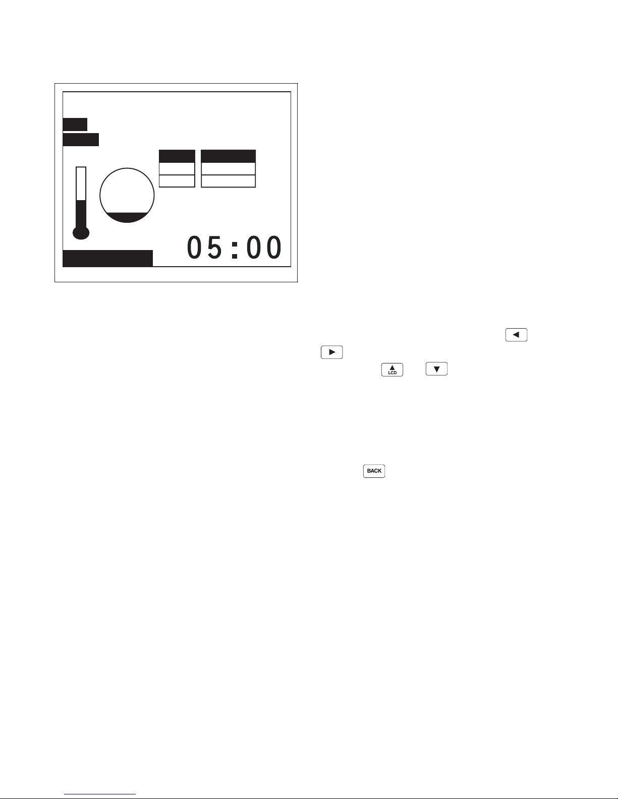
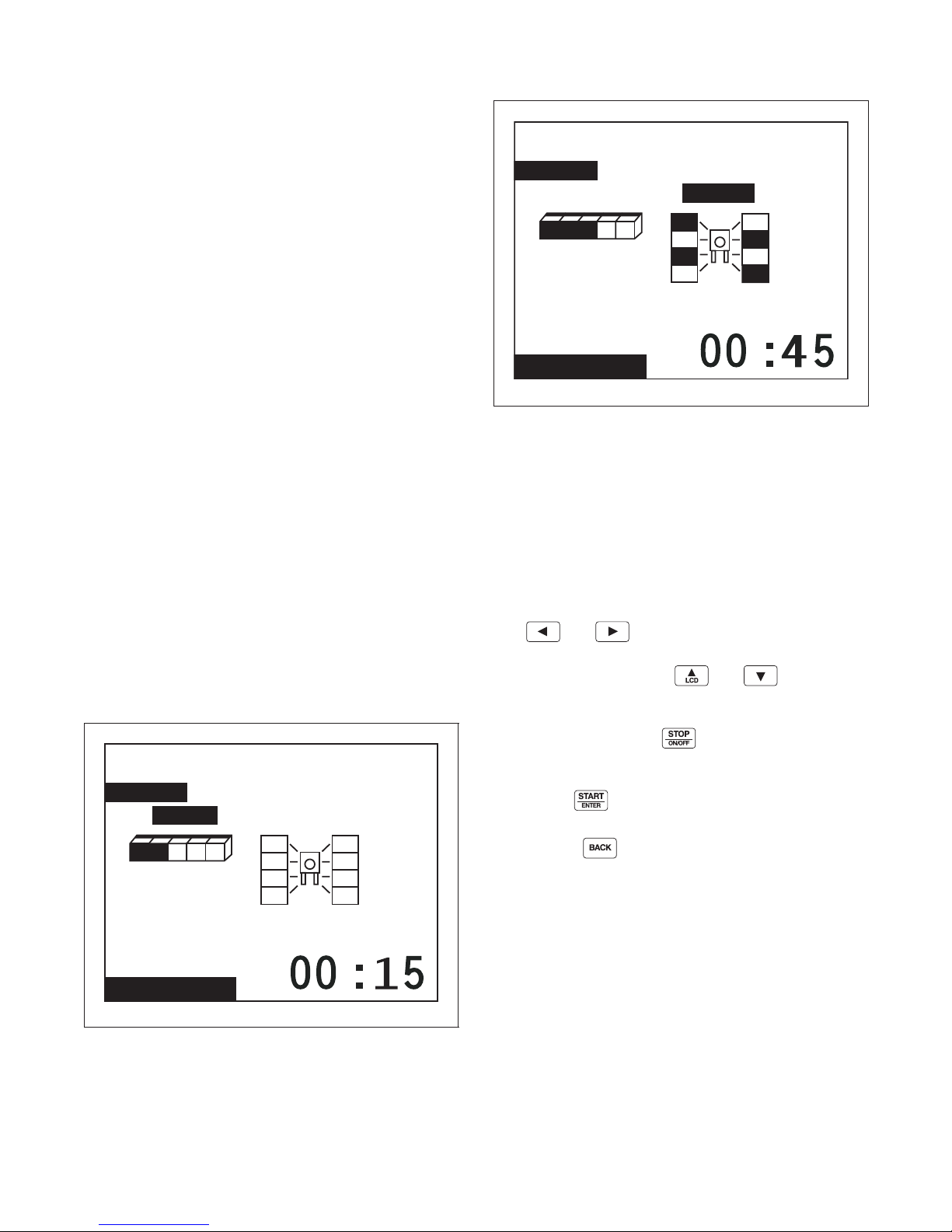
The Run Menu cannot be navigated by manipulating
the arrow keypads. Press keypad to advance the
cycle one step. The Control cannot advance into a
Spray Rinse Extract or an Extract Cycle Step.
Advancing the steps within a cycle also depends on
whether the option has been toggled on or off in the
Rapid Advance Menu.
The Run menus include the Run Menu, the Run
Diagnostic Menu, and the various sub-screens of the
Run Diagnostic Menu. Press the keypad to jump
to the Run Diagnostic Menu.
Press the keypad to stop the cycle in any of the
Run menus.
When the keypad is pressed, the display will
jump to the Cycle Stopped Menu showing an
hourglass.
Figure 7
F8434101
© Copyright, Alliance Laundry Systems LLC – DO NOT COPY or TRANSMIT
19
Page 22

Machine Cycle Definition and Operation
Contrast / Backlight Menu
Contrast Backlight
Contrast/Backlight Menu
PHM1008R
Figure 8
Press the keypad from Cycle Menu or Run
Menu to enter the Contrast Adjust/Backlight Menu.
The Contrast Adjust/Backlight Menu allows the user
to adjust contrast and turn the backlight on or off.
Close Door Menu
PHM843N
Figure 9
The Close Door Menu displays when loading door on
the machine is open and needs to be closed.
Close door to start cycle or press the keypad to
return to Cycle Menu.
Press the or keypad to highlight “Contrast”
or “Backlight” menu items.
Once the menu item has been selected, press the
or keypad to change contrast. The backlight is
either on or off and will have a factory default of on.
Press the keypad to enter the previous page.
If the Contrast Adjust/Backlight Menu is selected from
the Run Menu and the keypad is pressed, the
Cycle is aborted.
20
© Copyright, Alliance Laundry Systems LLC – DO NOT COPY or TRANSMIT
F8434101
Page 23

Machine Cycle Definition and Operation
Lubricate Bearings!
200 Hours Have Elapsed
Alarms
Run Diagnostic Menu
Drive Alarms
Inputs and
Outputs
Drive ID
Machine ID
Speed, Temp
and Level
Lubricate Bearings Menu
PHM1009R
Figure 10
The Lubricate Bearings Menu displays when the
machines has run for 200 hours and the bearing is the
type that can be lubricated. The Lubricate Bearings
Menu displays during Idle Mode when the Cycle
Menu is displayed. The Lubricate Bearing Menu and
Cycle Menu will alternate being displayed.
To remove the Lubricate Bearings Menu from being
shown during Idle Mode, the user must reset the
bearing timer by navigating to the System Menu and
reset the bearing timer. Press any keypad to display
Cycle Menu while viewing Lubricate Bearings Menu.
Run Diagnostic Menu
PHM1403R
Figure 11
The Run Mode Diagnostic Menu allows user to access
diagnostic information of the cycle currently running.
The menu contains speed, temperature, water level,
inputs and outputs, alarms, machine ID, Drive ID and
Drive Alarms.
While machine is running, press the keypad to
enter Run Diagnostic Menu.
Press the , , , or keypad to
navigate the menu.
Press the keypad to choose selection.
F8434101
© Copyright, Alliance Laundry Systems LLC – DO NOT COPY or TRANSMIT
If the keypad is pressed, display enters Run
Menu. If nothing is selected for 15 seconds, the
display will return to Run Menu.
21
Page 24

Machine Cycle Definition and Operation
Cycle Stopped
Heater Alarm Time Exceeded
Press START Key to Retry
Press STOP Key to Abort Cycle
Speed, Temp and Water Level Menu
1
2
3
6
7
11
1 Cycle Name 7 Programmed Water Temperature
2 Segment Name 8 Actual Water Level
3 Step Name 9 Programmed Water Level
4 Segment Time Elapsed 10 Actual RPM
5 Step Time Remaining 11 Run Screen Indicator
6 Actual Water Temperature 12 Cycle Time Remaining
Cycle01: Towels White Bleach
Segment01: Wash
Fill
Level
01
01
Actual
Run Menu
Temp
138 F
140 FProgram
01:42
01:42
RPM
40
PHM1083R
4
5
10
8
9
12
PHM1083R
The Speed, Temp, and Level Menu will display the
actual RPM, temperature and level, and program
values of the temperature and level during run mode.
The top portion of the display contains the same
information listed in the Run Menu detailing Cycle,
Segment, and Step operation.
Press keypad to enter Run Mode Diagnostic
Menu. Press keypad to stop the cycle, the
control will enter Cycle Stopped if there is rotation or
the Unlock Door page if there is not rotation. Press the
keypad to advance the cycle one step. The
Control cannot advance into a Spray Rinse Extract or
an Extract Cycle Step. Advancing the steps within a
cycle also depends on whether this option has been
changed to on or off in the Rapid Advance Menu.
Figure 12
Cycle Aborted Retry Menu
PHM1011R
Figure 13
The Cycle Aborted Retry Menu will be displayed for a
fill, drain or heater alarm time error. The display will
toggle this page with the Run Menu every three
seconds. Press to resume the cycle.
22
© Copyright, Alliance Laundry Systems LLC – DO NOT COPY or TRANSMIT
F8434101
Page 25

Machine Cycle Definition and Operation
Cycle Aborted
Water Level Sensor Error
Press BACK Key to
Return to Cycle Menu
Door Lock Error
Delayed Start Menu
Cycle01: Towels White Bleach
Hour1
Press keypad to abort the cycle. After two
minutes without a keypad press the control will abort
the cycle and go to the Cycle Aborted Fatal Menu.
Cycle Aborted Fatal Menu
PHM1012R
Figure 14
The Cycle Aborted Fatal Menu will be displayed
during any fatal errors or if the cycle is aborted from
the Cycle Aborted Retry Menu. Press the
keypad to exit the menu. Control will go to the Cycle
Stopped Menu or the Unlock Door Menu (depending
on if there is rotation or water present).
Cycle Stopped Menu
PHM1013R
Figure 16
The Cycle Stopped Menu is displayed while the
control is waiting for the basket to stop spinning. After
rotation is complete and the water has drained from the
machine the control will go to the Unlock Door Menu.
Delayed Start Menu
Error Menu
Figure 15
The Error Menu will be displayed if an error occurs in
Idle Mode. The control will return to the previously
displayed menu when the error clears.
PHM1438R
PHM1014R
Figure 17
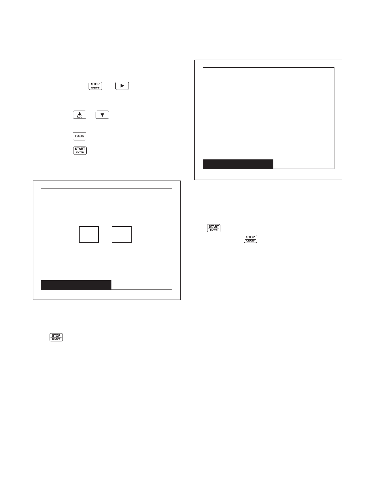
The Delayed Start Menu allows user to select in how
many hours the cycle should start.
Delayed Start Menu is only available from the Cycle
Menu.
If the loading door is opened, if the keypad is
pressed, or if there is a power failure during the delay,
the Delayed Start is aborted and is recorded as an
aborted cycle in the Last 10 Cycles Rapid Advance or
Stopped Audit Queue.
F8434101
© Copyright, Alliance Laundry Systems LLC – DO NOT COPY or TRANSMIT
23
Page 26
Machine Cycle Definition and Operation
Delayed Start
Cycle01: Towels White Bleach
hh mm
Press Start to Run Cycle
Press Stop to Abort
Delayed Start Activated
059:
Delayed Start
Cycle01: Towels White Bleach
Press Start to Run Cycle
Press Stop to Abort
Machine Will Start
Automatically in
59
Seconds
NOTE: 24 hours is the maximum delayed start
time.
To activate a delayed start cycle:
1. Select the desired cycle for delayed start.
2. Press and hold and keypads. The
cycle that was selected will display with the
Delayed Start Menu.
3. Press the or keypad to alter the
number of hours.
4. Press the keypad to go back to Cycle Menu.
5. Press the keypad to enter Delayed Start
Countdown Time Menu.
Delayed Start Countdown Menu
Delayed Start Final Countdown
Menu
PHM1016R
Figure 19
The Delayed Start Final Countdown Menu is
displayed during the last sixty seconds before the
control is automatically started. The audio signal will
sound one second on and one second off.
The keypad will start the selected cycle
Figure 18
The Delayed Start Countdown Menu will be shown
after the delayed start feature has been activated.
Press keypad to return to the Cycle Menu. When
there is sixty seconds left on the countdown, control
will enter the Delayed Start Final Countdown Menu.
immediately. The keypad will jump to the Cycle
Menu.
PHM1015R
24
© Copyright, Alliance Laundry Systems LLC – DO NOT COPY or TRANSMIT
F8434101
Page 27

Menu Navigation
The UniLinc
The front end control allows the user to control
machine operation by pressing keypads to select
options on the display menus and by navigating
between display menus.
The control has four ways to navigate to program, edit,
and select items in menus
Menu Navigation on a Single Screen
The Menu Navigation on a single screen displays a list
of items arranged either left to right and/or top to
bottom on the screen. A highlighted box shows the
selected item in the menu. Press the directional arrow
keypads to move the highlighted box between choices.
Press the keypad to select an item. Press
the keypad to turn an item on or off.
NOTE: In Cycle Menu, the highlighted box
remains in the center, and the cycles scroll as the
directional keypads are pressed.
Menu Navigation with Parameters
Another type of menu similar is a menu with
modifiable parameters. The and keypads
are used to navigate through the screens. The
and keypads are used to change the valve of the
highlighted item.
An example is the Temperature Menu under Global
Setup. The menu items are positioned vertically, but
the and keypads are used to navigate
through the different items while the and
keypads are used to adjust the values.
Screen to Screen Navigation using
the Arrow Keypads
In Screen to Screen Navigation, the or
keypad are used to go from one menu page to the next
(i.e., moving from Alarms [1 of 3] Menu to Alarms
[2 of 3] or Alarms [3 of 3] menus), if a menu cannot fit
entirely on the same page. The Laundry Management
Menu uses this navigation method.
Navigation in String Edit Mode
The String Edit Mode is used when a letter or numeric
value has to be modified or created. The highlighted
box is moved over the editable item and
the keypad is pressed. The mode can be verified
by seeing the first character in the item with a blinking
underscore underneath. The character can then be
changed by using the and keypads.
Press the keypad to insert a space in place of the
currently selected character.
For example, the Cycle Name can contain the capital
letters “A” through “Z”, small letters “a” through “z”,
the numbers “0” through “9”, and special characters.
The user can go forward to the next character in the
item by using the keypad. Press the
keypad to go backward a character. If the first
character in the item is selected and the keypad
is pressed, the cursor will go to the last character of the
item. Thus, the cursor will move only within the item
when the horizontal keypads are pressed.
Another example of the edit mode is when the user is
programming the time. In the edit mode when
programming a time, the only characters that can be
selected are “0” through “9” when using the
F8434101
© Copyright, Alliance Laundry Systems LLC – DO NOT COPY or TRANSMIT
or keypad.
25
Page 28
Menu Navigation
Cycle Menu
System Menu
Diagnostic Menu
Run Menu Service Menu
Contrast Adjust Menu
Auto - Leak Detect Menu
Close Door Menu
Lube Bearing Menu
Delayed Start Menu
. . . . . .
Program Menu
Laundry Management
Menus
Machine ID Menu
Alarms Menu
Water Leak Detection Menu
Factory Valve Purge
Test Cycle
Save Changes Menu
(After all Step Menus
and Global Menus
except Factory
Defaults)
Global Setup Menu
Language Menu
Date/ Time Menu
Water Level Menu
Audio/ Ext Signl Menu
Balance Retry Menu
Water Mgmt Menus
Alarms Prog Menu
Rapid Advance Menu
Shake Out Menu
Temperature Menu
Banners Menu
Test Menu
Modify Cycle Menu
Reuse Step Menu
Supply A & B Step Menus
Cool Down Step Menu
Drain Step Menu
Spray Rinse Extract Step Menu
Extract Step Menu
EOS Audio Signal Step Menu
All Defaults Confirmation
Factory Defaults Menu
Agitate Step Menu
Fill Step Menu
Second
Confirmation
Water Level Confirmation
Temperature Confirmation
Alarms Confirmation
Audio Confirmation
Drive ID Menu
Drive Alarms Menu
General Purpose Signals Menu
Drive Test
Inputs Outputs
PHM1483R
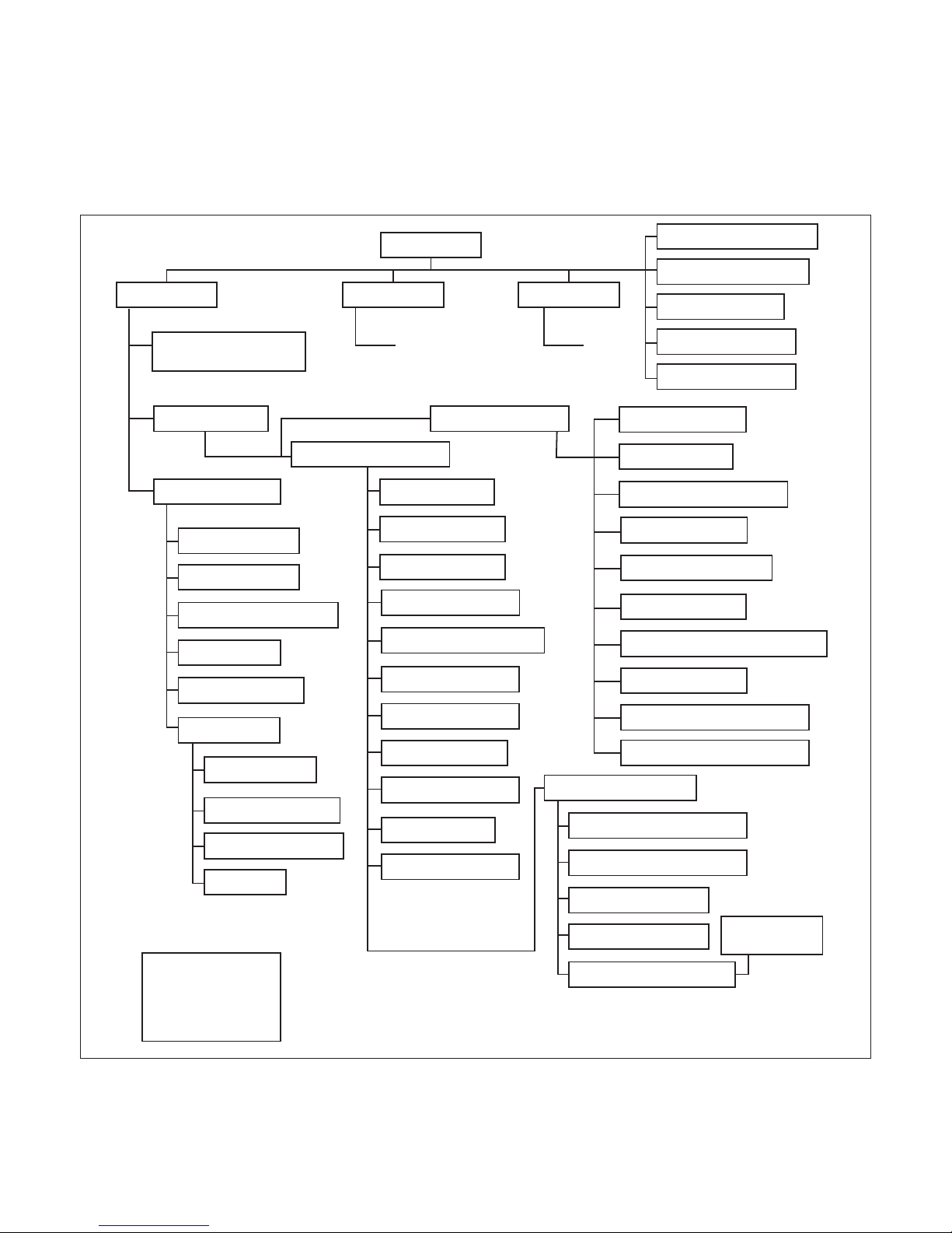
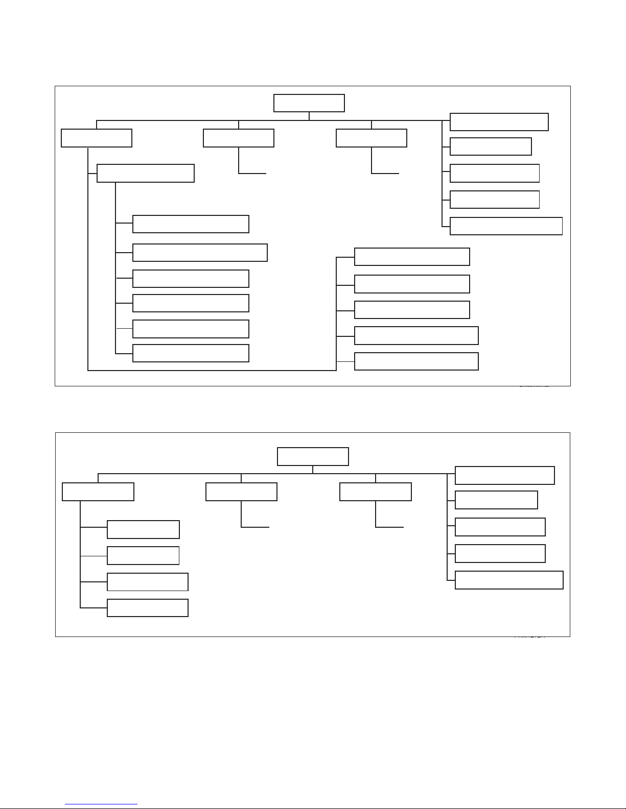
Display Screen Maps
Refer to the following charts for maps of all of the
display menus.
System Menu Map Tree
26
© Copyright, Alliance Laundry Systems LLC – DO NOT COPY or TRANSMIT
Figure 20
F8434101
Page 29
Run Menu Map Tree
Cycle Menu
Run Menu Service Menu System Menu
Contrast Adjust Menu
Close Door Menu
Lube Bearing Menu
Delayed Start Menu
Auto - Leak Detect Menu
. . . . . .
Contrast Adjust Menu
Open Door Menu
Cycle Stopped Menu
Cycle Aborted Retry Menu
Cycle Aborted Fatal Menu
Run Diagnostic Menu
Speed, Temp, Level Menu
Run Alarms Menu
Run Drive Alarms Menu
Run Mode Inputs Outputs Menu
Drive ID Menu
Machine ID Menu
PHM1405R
Cycle Menu
Service Menu Run Menu System Menu
Contrast Adjust Menu
Close Door Menu
Lube Bearing Menu
Delayed Start Menu
Auto - Leak Detect Menu
. . . . . .
Daily Menu
Monthly Menu
Quarterly Menu
Weekly Menu
PHM1272R
Menu Navigation
Figure 21
Service Menu Map Tree
Figure 22
F8434101
© Copyright, Alliance Laundry Systems LLC – DO NOT COPY or TRANSMIT
27
Page 30
Programming UniLinc
Laundry
Management
System Menu
Reset Bearing
Timer
DiagnosticProgram
Save Changes?
NoYe s
System Menu
PHM1020R
Figure 23
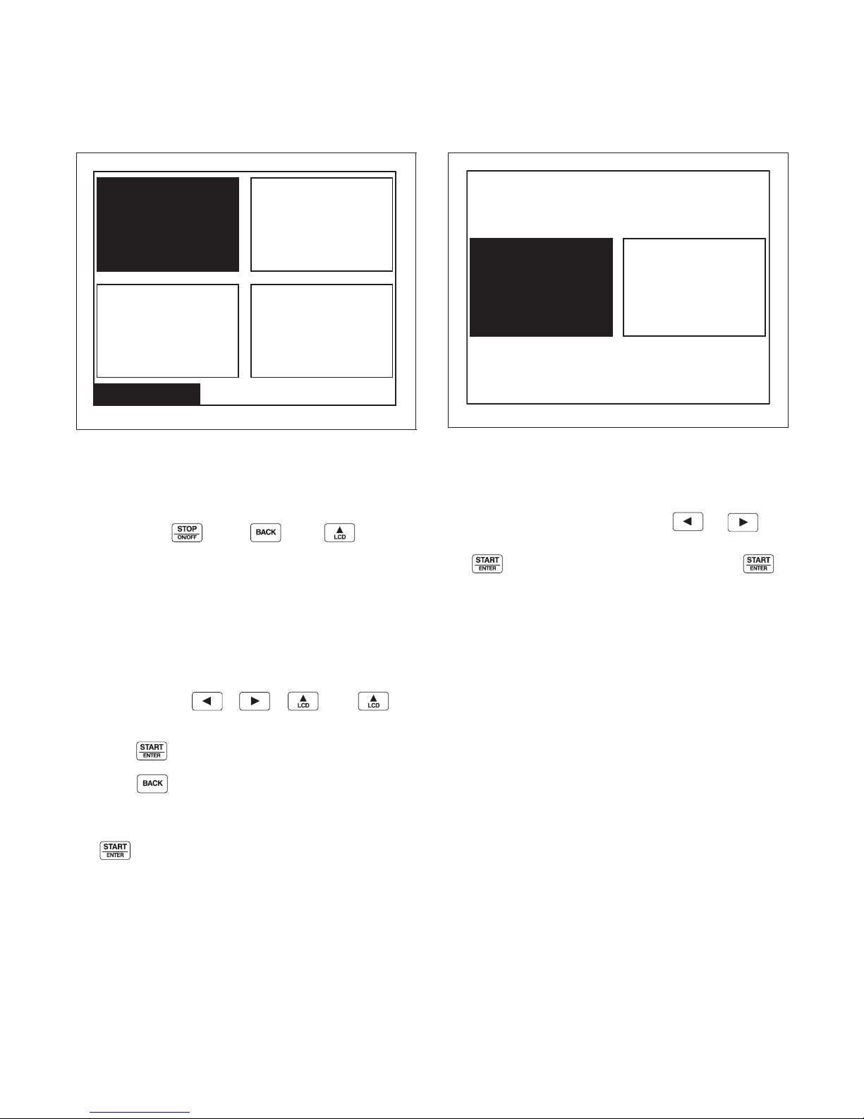
The System Menu allows the user to access: cycle
programming, diagnostics, laundry management,
bearing timer reset/reset bearing timer.
Press and hold , then, , then to enter
the System Menu.
The System Menu is a submenu of the Cycle Menu.
The navigation of the System Menu is different from
the Cycle Menu. In the Cycle Menu, the highlighted
text box was stationary. In the System Menu, the
ARROW keypads control the location of the
highlighted text box. Text will remain at the same
location but the highlighted box will move when the
text box when the , , , and
keypads are pressed.
Save Changes Menu
PHM1021R
Figure 24
The Save Changes Menu is used to confirm
programming changes when modifying a cycle or the
parameters of the Global Settings. The Save Changes
Menu will default to Yes. Using the or
keypad will move the cursor between Yes or No. Press
the keypad to make a selection. Once the
keypad is pressed, the display will either return to the
Modify Cycle Menu or the Global Setup Menu
depending in which submenu the display was in.
Press the keypad to enter selected menu.
Press the keypad to return to the Cycle Menu
screen.
If the user highlights Reset Bearing Timer and presses
the keypad, the text changes to Bearing Timer
Reset and the control resets the total operation time
since the bearings were last serviced. This menu item
will not be an option on machines that do not have a
greasable bearing.
28
© Copyright, Alliance Laundry Systems LLC – DO NOT COPY or TRANSMIT
F8434101
Page 31
Program Menu
Program Menu
Modify Cycle Global Setup
Modify Cycle
Cycle01: Towels White Bleach
Segment01: Prewash
Program Menu
PHM1022R
Figure 25
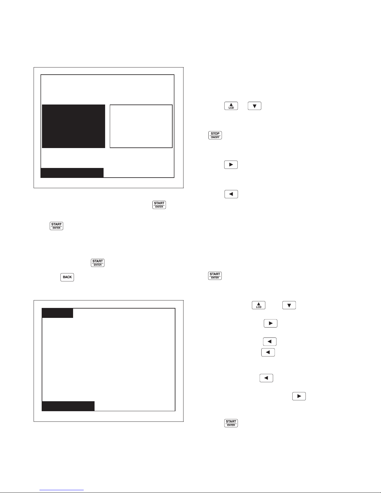
In System Menu, select Program and press .
To program cycles, select Modify Cycle and
press .
To change properties that will affect the machine
globally, select Global Setup (i.e., water temperature
Cold to 35°F, will make the cold water temp 35°F for
all cycles) and press .
Press the keypad to return to System Menu.
Modify Cycle
The Modify Cycle Menu is used to program the
cycles. For programming steps, the Modify Cycle
Menu changes to the Step Menu.
The Cycle Number will be highlighted when the
Modify Cycle is first displayed.
Press the or keypad to change cycle
selections.
The cycle can be turned on and off by pressing
the keypad. If the cycle is turned off, the Cycle
Name will display “Off” and the user will not be able
to make any changes to the cycle.
Press the keypad to make the highlighted box
move to the cycle name to the right of the cycle
number.
Press the keypad to make the display jump to
the End of Segment (EOS) Audio Signal Step Menu of
the last segment of that cycle which is programmed
“On”.
NOTE: All segments and available steps have to be
scrolled through even though they may be shut off.
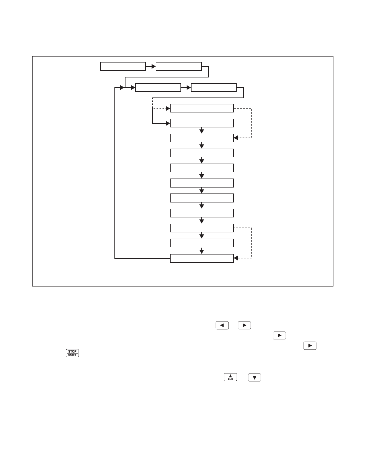
Figure 27 illustrates the flow of the cursor during
the programming of a cycle.
To edit a cycle name, select the cycle name and press
the keypad.
The first character of the Cycle Name will have a
blinking underscore underneath to display it is ready
for editing. Use the and keypads to select
the different characters. After the desired character has
been selected, press the keypad to save the
character and move to the next character in the string.
The user may press the keypad to go back a
Figure 26
F8434101
© Copyright, Alliance Laundry Systems LLC – DO NOT COPY or TRANSMIT
PHM1023R
character. Pressing the keypad when located on
the first character will take the user to the last
character of the string, which may be a blank space.
Continue pressing the keypad to move to
desired character. The blinking underscore is under the
last character of the string and the keypad is
pressed, the blinking underscore will move to the first
character of the string.
Press the keypad to exit string edit mode.
29
Page 32
Program Menu
NOTE: Refer to Tab le 2 for a chart of available
letters, numbers and symbols.
Press the keypad to move highlighted box to
Segment Number or press the keypad to move
the highlighted box back to the Cycle Number. While
the Segment Number is highlighted, the Segment
pressing the or keypad. The Segment
Name choices are Prewash, Wash, and Rinse.
NOTE: OFF may also be displayed in the Segment
Name position if the segment number had been
turned off previously, but is not a menu choice.
Press the keypad to move highlighted box back
Number can be turned on or off by using the
keypad. If turned off, all sub programming steps will
become inaccessible.
to the Segment Number. Press the keypad to
move into step menus of cycle segment. Steps have
separate menus (different screens) from the Modify
Press the or keypad to change segment
selections.
Press the keypad to move the highlighted text
Cycle Menu. However, when the highlighted cursor is
on the Step Name and the keypad is pressed, the
display will jump back to the Modify Cycle Menu and
the Segment Name will be highlighted.
box to the Segment Name.
While the Segment Name is selected, the user selects
the Segment Name from a list of three choices by
Press the keypad to jump to the Save Changes
Menu.
Available Characters
ABCDE FGH I JKLMNOP
QRSTUVWXYZabcdef
ghi jk lmnopqrs t uv
wxyz0123456789! "
#$%&'()*+,-./:;<
=>?@[\ ]^_`{|}~€‚
ƒ„…†‡ˆ‰Š‹ŒŽ‘ ’“”•
–—˜™š ›œžŸ ¡¢£¤¥ ¦
§¨©ª«¬-®¯°±²³ ´μ¶
· ¸ ¹ º »¼½¾¿ АБВГДЕЖ
ЗИЙКЛМНОПРСТУФХЦ
ЧШЩЪЫЬЭЮ Я абвгдеж
зийклмнопрстуфхц
чшщъыьэюя
30
© Copyright, Alliance Laundry Systems LLC – DO NOT COPY or TRANSMIT
Tab le 2
F8434101
Page 33
Cycle, Segment and Step
Cycle NameCycle Number
Segment Name
Reuse Fill Step¹
Fill Step
Segment Number
Supply A Step
Supply B Step²
Agitate Step
Cooldown Step
Drain Step
Spray Rinse Extract Step
Extract Step
General Purpose Signals
EOS Audio Signal Step
PHM1484R
1
Reuse Fill Step is not used unless active in the Global Settings.
2
Supply B Step will not be shown if Supply A step is turned off.
PHM1484R
Programming Flow Diagram
Program Menu
Step Menu Navigation
Figure 27
Step Menus are a subgroup of the Modify Cycle Menu
and the navigation is very similar to the navigation of
the Modify Cycle Menu. When a step menu is first
displayed, the step name will be highlighted. While the
step name is highlighted, it can be toggled on or off by
pressing the keypad. If the Step is toggled from
OFF to ON, then the last programmed parameters will
be displayed. The programmable parameters (i.e.,
water temperature, water level, time, etc.) are based on
the step being programmed. For instance, the water
temperature is available in the Fill Step but not the
Reuse Fill Step, so, the water temperature parameter
will not be shown in the Reuse Fill Step.
NOTE: Reuse Fill Step is only available when the
different Step parameters can be selected.
Press the or keypad. To view all steps of a
segment, continue pressing the keypad until the
EOS Audio Step is displayed. Pressing the
keypad again will take screen to Save Changes Menu.
After selection, the cycle modify section is displayed
with highlighted box on segment just viewed/changed.
Pressing the or keypad can adjust the
Step Name and parameters.
F8434101
© Copyright, Alliance Laundry Systems LLC – DO NOT COPY or TRANSMIT
31
Page 34
Program Menu
Modify Cycle
Cycle01: Towels White Bleach
Segment01: Prewash
Reuse Fill:
Level
High
Valve
Reuse A
Reuse B
Aux Fill
To adjust time, the user must press the keypad to
get to the Time Edit Mode. The Time Edit Mode
works exactly like the String Edit Mode. The
and keypads move the cursor between digits.
The and keypads change the number.
To set parameters in the step menus, move highlight
box to desired step parameter and press ,
the and keypads to change values. In
menus that do not have many values or items to
choose from the vertical arrow keypads will toggle.
NOTE: To change a value, press the or
keypad every time a different item is to be selected.
In menus that have many values or items, the user will
be able to either toggle or slew the or
keypad. Slewing the keypads is when the user holds
down a keypad for a specified amount of time and the
value automatically scrolls through the parameter
being modified. The slewing is based on how much
time the user holds down the keypad. If the keypad is
held down for longer than 2 seconds the value will
begin to scroll.
During the programming of a step, if the keypad
is pressed, the display will jump to the Save Changes
Menu.
Reuse Fill Step Menu
PHM1025R
Figure 28
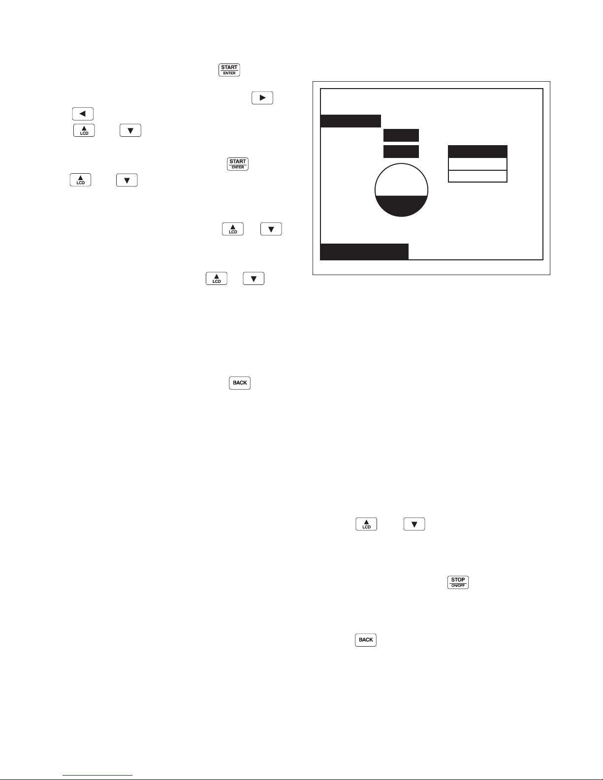
The Reuse Fill Step Menu is used to program the
Reuse Fill step while modifying the Cycle. The Reuse
Fill Step can only be viewed if the Water Reuse
Parameter is turned on (refer to Global Setup Water
Management section), and the fill step for the segment
is turned off otherwise this step is skipped and not
shown. The time for this step is fixed at 5 minutes. The
Fill Alarm is not active for this step. However, the
control will energize cold fill and spray after five
minutes until the water level reaches the programmed
level.
The first programmable parameter of the Reuse Fill
step is the water level. The target water level is either
the programmed global value (High, Medium or Low)
or a specific water level value. Global water level
values are set in the Water Level Menu (refer to Global
Setup, Water Level). For the specific water level value,
1-30 may be selected. The water level can be changed
using the and keypads.
The parameter after water level is valve selectors.
Reuse Fill A, Reuse Fill B, or both may be activated
during the Reuse Fill step. The valve can be selected
and deselected by pressing the keypad. If Reuse
Fill A and Reuse Fill B are deactivated, Aux Fill will
activate by default. If Water Reuse is enabled, the Aux
Fill will be on by default.
Press the keypad to return to Save Changes
Menu.
32
© Copyright, Alliance Laundry Systems LLC – DO NOT COPY or TRANSMIT
F8434101
Page 35
Program Menu
Modify Cycle
Cycle01: Towels White Bleach
Segment01: Prewash
Fill:
Tem p
115 F
Heat
m m : s s
Time
No Heat
To Ta rg e t
Maintain
Both
Fill
Spray
Level Valves
Low
g
Fill Step Menu
PHM1407R
Figure 29
The Fill Step Menu is used to program the fill step.
The Fill Step contains the parameters the machine will
use when it fills.
Water temperature can be either a global value or a
specific temperature. The global settings are Cold
(COLD), Warm (WARM), or Hot (HOT). The values
for these global settings are set in the Global Setup
Temperature Menu. The specific temperature selection
can either be in Celsius or Fahrenheit depending on
which is chosen in the Global Setup.
The water level can be set to a global value, a specific
level from 1 to 30, or to overflow (OVFL). The global
settings are Low (LOW), Medium (MED), or High
(HIGH).
The valves used to fill can be selected individually.
The valve settings are Fill, Spray or Both.
NOTE: Advance Options must be enabled in the
Water Management Menu in Global Setup to
program the valves used during a fill.
The next parameter controls the heater while the
machine is actually in the Agitate Step. This parameter
is only displayed if a heater is present.
There are three choices on heater equipped machines.
The choices are “No Heat”, “To Target”, and
“Maintain”. If “No Heat” is selected, the heater will
not function during the Agitate Step. If “To Target” is
enabled, the heater will turn on in the Agitate Step and
reach the desired water temperature. Once the desired
water temperature is reached the heater shuts off. If
“Maintain” is selected, the heater is turned on and off
as necessary throughout the Agitate Step to maintain
the desired water temperature.
The time that is programmed refers to the Fill Alarm
Time. If the time is set to the global Fill Alarm Time, a
“g” will be displayed to the left of the time. The time
can be changed to a specific value for an individual
cycle by entering Time Edit Mode, using and
keypads to navigate between minutes and
seconds, and
and keypads to change the
time. The Fill Alarm Time is the amount of time
allowed for fill to complete. If fill is not reached by
Fill Alarm Time, the control will enter Error Mode.
The Reuse Fill Step and Fill Step cannot both be
enabled in the same segment. If the Reuse Fill Step is
enabled then the Fill Step will be turned off.
Press the keypad to enter the Save Changes
Menu.
F8434101
© Copyright, Alliance Laundry Systems LLC – DO NOT COPY or TRANSMIT
33
Page 36
Program Menu
Modify Cycle
Cycle01: Towels White Bleach
Segment01: Prewash
Supply A:
Internal
External
m m : s s
Time
ESI
ES2
ES3
ES4
ES5
ES6
ES7
ES8
S3 S4 S5SI S2
Modify Cycle
Cycle01: Towels White Bleach
Segment01: Prewash
Supply B:
Internal
External
m m : s s
Time
ES2
ES4
ES5
ES7
S4 S5SI S2 S3
ESI
ES3
ES6
ES8
Heater Option
If a Heater is present it can be programmed to heat
water during an Agitate cycle step. The Fill step of a
cycle segment contains the Heater programming
options for that segment. If the Heater is programmed
to On in the Fill step of a segment, the Heater is turned
on during the Agitate cycle step in order to heat the
water to the target temperature specified by the
programming information of the segment’s Fill step.
The target temperature can be programmed for the
segment in one of two ways. The Fill Step can be
programmed to use the Hot, Warm or Cold Global
temperature value. The Fill step can also be
programmed to a water temperature specific to this
segment. During the initial heater on time, the
remaining cycle time count-down will pause until the
target temperature is reached. If the heater is turned on
for more than the Global Heater Alarm time and the
desired temperature is not reached, the heater is turned
off and the Cycle Stopped Error Menu is displayed
prompting for user input. The Heater Error is logged.
The user may either abort or continue the cycle. If the
Fill Step for this segment is programmed to maintain
the heated water temperature, the heater will be turned
back on in the Agitate step any time the water
temperature has fallen more than five (5) degrees F
below the programmed target temperature. If the water
level ever falls below the programmed water level, the
heater will be turned off until the programmed water
level is reached again.
Supply A and B Step Menu
PHM1028R
Figure 31
The Supply A and Supply B Step Menus are used to
control which supply or supplies that are activated
during a Segment and the duration of the dispensing.
The Internal Supplies are listed from S1 to S5 and
external supplies are numbered ES1 through ES8. Any
of the internal, external, or both type of supplies can
be turned on or off during Supply Step A or Supply
Step B. Any combination of SUPPLIES is possible in
both menus.
The and keypads are used to move the
cursor to the different parameters and Internal
Supplies 1 through 5. The and keypads are
used to move the cursor to the External Supplies 1
through 8. Once a supply has been chosen, it is
selected by pressing the keypad. The supply is
activated if it is highlighted. The time can be edited for
each supply step by moving the highlighter box to
time. Press . Blinking underline indicates the
number is ready to be changed.
34
Figure 30
© Copyright, Alliance Laundry Systems LLC – DO NOT COPY or TRANSMIT
Pressing the keypad will jump to the Save
Changes Menu.
PHM1027R
F8434101
Page 37
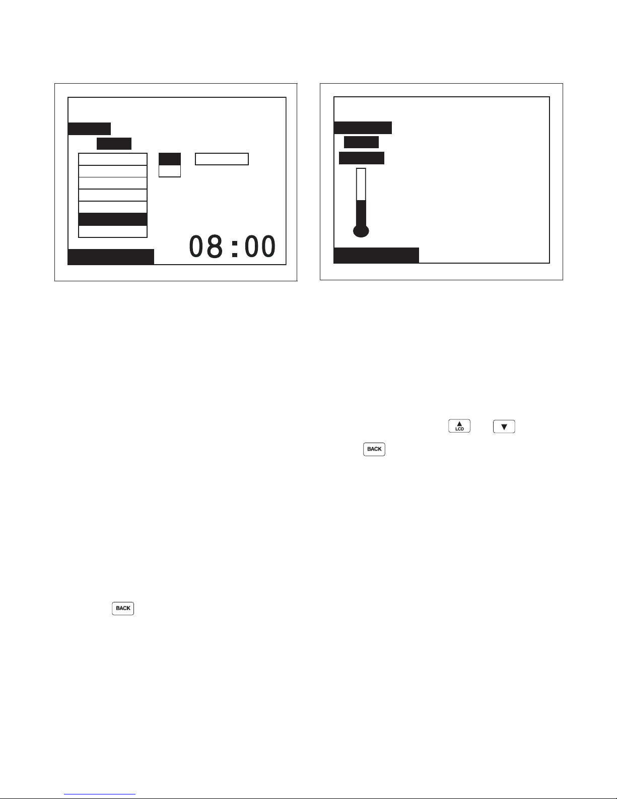
Program Menu
Modify Cycle
Cycle01: Towels White Bleach
Segment01: Prewash
Agitate:
Type
m m : s s
TimeSpeedRecirc
Normal
No Rotation
Drain Only
3F/27P/3R
10F/20P/10R
Continuous
On
Off
4F/56P/4R
18F/3P/18R
Modify Cycle
Cycle01: Towels White Bleach
Segment01: Prewash
Cooldown:
Temp
GLOBAL
Agitate Step Menu
PHM1491R
Figure 32
The purpose of the Agitate Step Menu is to program
the parameters used while the machine is performing
the Agitate Step. The Agitate cycle step can be turned
on or off. The type of agitation is the first available
parameter. The agitation type parameter menu has
seven (7) choices with 18F/3P/18R (18 seconds
forward, 3 seconds pause, and 18 seconds reverse)
being the default.
The recirculation parameter controls the operation of
the recirculation pump during machine operation. The
user can either turn it on or off. If the water
recirculation option is not enabled in Global Setup
parameter, then this parameter will not display. The
Wash speed can be programmed to either Normal
Wash speed, Reduced Wash speed or a specific RPM
from 10-50.
Cool Down Step Menu
PHM1030R
Figure 33
The Cool Down Step Menu gives the user the option to
set the Cool Down Option after the Agitation Step.
The Cool Down cycle step can be turned on or off. If
turned off, the control will advance to the next cycle
step (Drain).
The temperature setting allows the user to set the Cool
Down temperature of the water after the Agitation
Step has ended. The temperature will default to cool
down temperature set in Global Setup. To change cool
down temperature, press the and keypads.
Press the keypad to jump to the Save Changes
Menu.
The Agitate step can be programmed to a time from
one (1) minute to 30 minutes.
NOTE: If the Agitate type is programmed to a
value of “No Rotation”, the cycle step time can be
programmed to a value from one (1) minute to 24
hours.
Pressing the keypad will jump to the Save
Changes Menu.
F8434101
© Copyright, Alliance Laundry Systems LLC – DO NOT COPY or TRANSMIT
35
Page 38
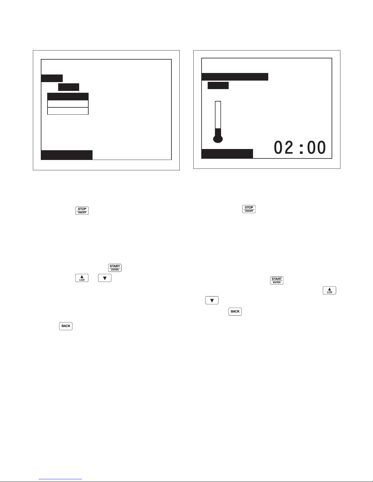
Program Menu
Modify Cycle
Cycle01: Towels White Bleach
Segment01: Prewash
Drain:
Type
Reuse A
Reuse B
Main Drain
Modify Cycle
Cycle01: Towels White Bleach
Segment01: Prewash
Spray Rinse Extract:
Temp
m m : s s
Time
Cold
Drain Step Menu
PHM1031R
Figure 34
The Drain Step Menu allows the user to activate or
deactivate the drain step and control where the water is
drained. The Drain cycle step can be turned on or off
by pressing the keypad. If turned off, the menu
will show that the Spray Rinse Extract and Extract
Steps are unavailable for that cycle segment.
If global water reuse is enabled the drain type allows
the user the option of pumping the wash water to
Reuse A or Reuse B or sending it to the Main Drain. If
global water reuse is disabled the screen will show
Main Drain only. Using the keypad to select
Type, press the or keypad to select the
drain type. If the Drain Step is turned off, then the
Type parameter menu will not be present and the text
“Extract steps are disabled” will be displayed. With
the Drain Step disabled, the next available segment
step would be the EOS Audio Signal Menu.
Press the keypad to jump to the Save Changes
Menu.
Spray Rinse Extract Step Menu
PHM1032R
Figure 35
The Spray Rinse Extract Step Menu is used to program
the temperature and time for the Spray Rinse Extract
Step. The Spray Rinse Extract cycle step can be turned
on or off with the keypad. If turned off, the
control will advance to the next available cycle step. If
Spray Rinse Extract option is not available for the
machine, the step will be skipped and control will
advance to Extract Step Menu.
The temperature is programmed by selecting the Temp
parameter and then using the vertical keys to change
the thermometer to Cold, Warm or Hot. The Spray
Rinse Extract time is programmed by moving
highlight box to Time. Press . Blinking underline
is located in character ready to be changed. Use
and keypads to change number as desired.
Pressing the keypad will jump to the Save
Changes Menu.
36
© Copyright, Alliance Laundry Systems LLC – DO NOT COPY or TRANSMIT
F8434101
Page 39
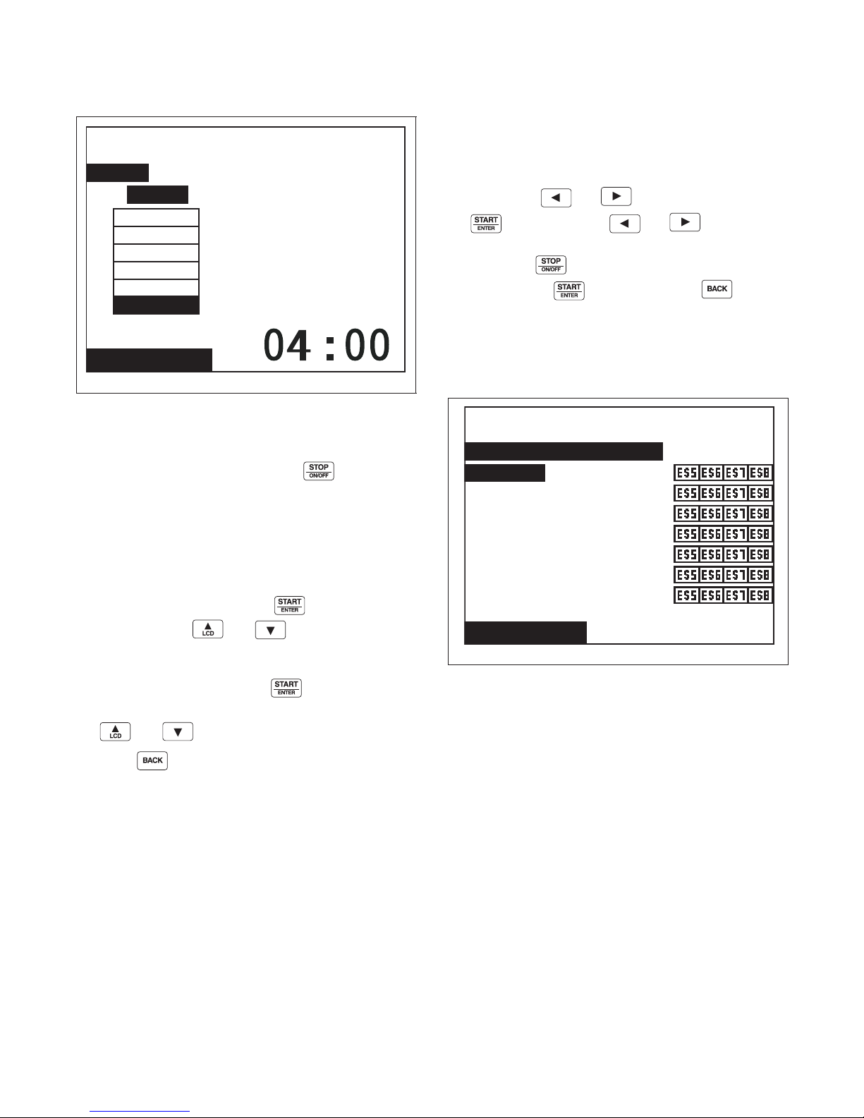
Program Menu
Modify Cycle
Cycle01: Towels White Bleach
Segment01: Prewash
Extract:
Speed
m m : s s
Time
Very Low
Low
Medium
High
Very High
Ultra High
Modify Cycle
Cycle01: Towels White Bleach
Segment01: Prewash
General Purpose Signals:
Reuse Fill
Fill
Agitate
Cooldown
Drain
Spray Rinse Extract
Extract
Extract Step Menu
PHM1408R
Figure 36
The Extract Step Menu is used to program the motor
speed and time for the Extract Step. The Extract Step
can be turned on or off by using the keypad. If
turned off, the control will advance to End of Segment
Audio Signal step.
General Purpose Signals Menu
The General Purpose Signals Menu is used to program
external supply Signals (ES5-ES8) during each
segment’s Reuse Fill, Fill, Agitate, Cooldown, Drain,
Spray Rinse Extract and Extract Steps. To choose a
step, press the
the
keypad. Use the and keypads to
move the cursor to the desired external supply signal
and press the keypad to select external supply
signal. Press the keypad. Press the keypad
to jump to the Save Changes Menu.
NOTE: To access the General Purpose Signals
Menu, the Advance Options must be enabled in the
Water Management Menu in Global Setup.
and keypads and press
NOTE: If Advance Options are enabled in the
Water Management Menu, the next option will be
General Purpose Signals Menu.
To choose a motor speed, press while selecting
Speed and use the and keypads to make a
selection. The motor speed is selected from the menu
bar. The Extract time can be programmed by moving
highlighted box to Time. Press . Blinking
underline will indicate number to change. Use
the and keypads to change numbers.
Press the keypad to jump to the Save Changes
Menu.
F8434101
Figure 37
© Copyright, Alliance Laundry Systems LLC – DO NOT COPY or TRANSMIT
PHM1420R
37
Page 40
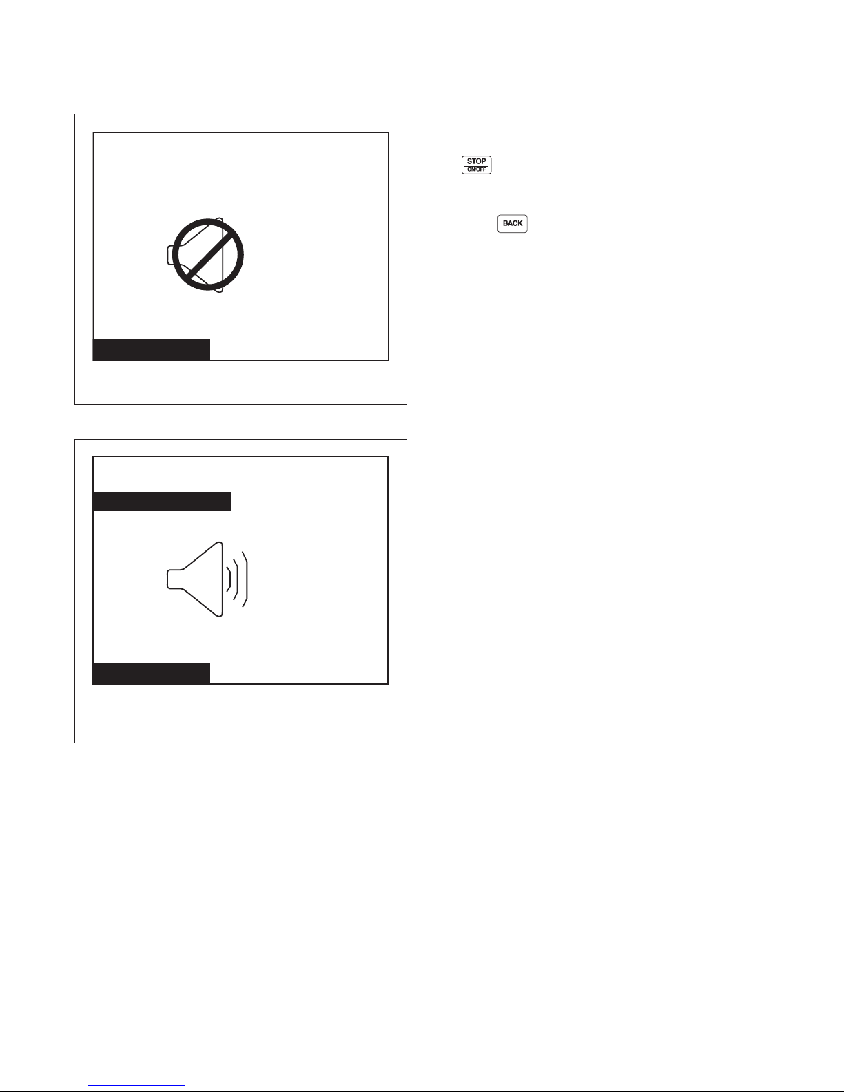
Program Menu
Modify Cycle
PHM1034R
Cycle01: Towels White Bleach
Segment01: Prewash
EOS Audio Signal:
Off
Modify Cycle
PHM1035R
Cycle01: Towels White Bleach
Segment01: Prewash
EOS Audio Signal:
End of Segment Audio Signal Step Menu
PHM1034R
Figure 38
The End of Segment (EOS) Audio Signal Step Menu
allows the user to set whether an audio signal is
activated at the end of a segment. The End of Segment
Audio Signal step can be turned on or off with
the keypad. If turned off, the control will
advance to the next cycle step (start of the next
segment, or the end of the cycle).
Press the keypad to enter the Save Changes
Menu.
On
Figure 39
38
© Copyright, Alliance Laundry Systems LLC – DO NOT COPY or TRANSMIT
PHM1035R
F8434101
Page 41
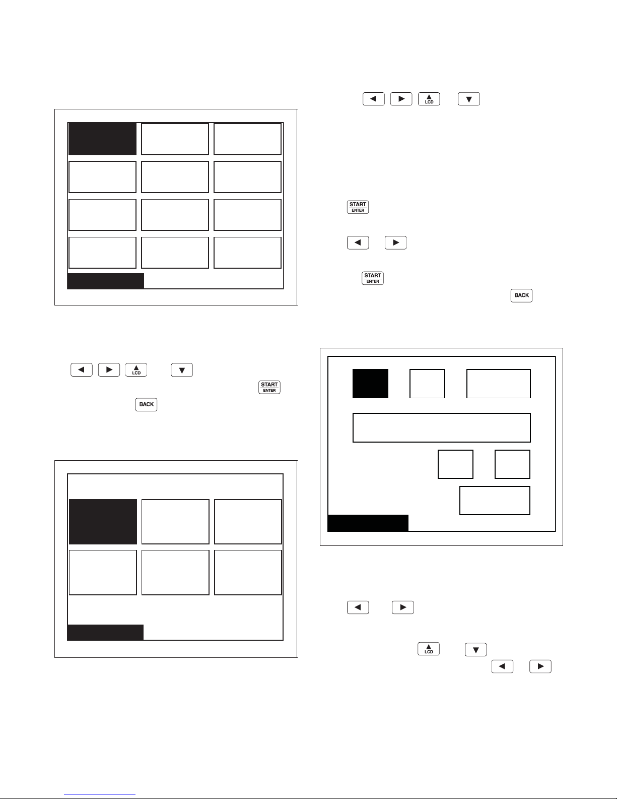
Global Setup
Global Setup
Date / Time Water LevelLanguage
Audio / Ext
Signal
Balance
Retry
Temp
Alarms
BannersShake Out
Water
Mgmt
Rapid
Advance
Factory
Defaults
Language Menu
DeutschFrançais Portuguese
Español ItalianoEnglish
Date / Time
Wednesday
18/
09 24
Yes
:
/
2006
Current Date
Day of Week
Local Time
Daylight Saving
01
Global Setup Menu
PHM1036R
Figure 40
The Global Setup Menu allows the user to make
changes to global properties of the machine. Use
the , , , and keypads to navigate
the menu. Select a menu item by pressing the
Press the , , , or keypad to move
the highlighted box through the different selections.
English is the default language.
NOTE: Menus related to cycle operation and
service are the only menus that will display in the
chosen language if English is not selected. All
System Menu sub-menus will remain in English.
Press to select a language. The Save Changes
Menu will display.
Press or to move highlighted box to “Yes”
or “No”.
Press the keypad to return to Global Setup
Menu. If no changes were made, press the
keypad to return to Global Setup Menu.
Date/Time Menu
keypad. Press the keypad to enter the Program
Menu.
Language Menu
The Language Menu is used to select the language
displayed. The user can choose English, Spanish,
Italian, French, German or Portuguese.
F8434101
Figure 41
© Copyright, Alliance Laundry Systems LLC – DO NOT COPY or TRANSMIT
PHM1037R
PHM1409R
Figure 42
The Date/Time Menu is used to set the date, day of the
week, time, and daylight saving option.
Press and keypads to move the
highlighted box through the different items in the
menu. Once the item is highlighted, the value can be
changed by using the and keypads. The
Save Changes Menu will display. Use or
to move highlighted box to “Yes” or “No”.
39
Page 42
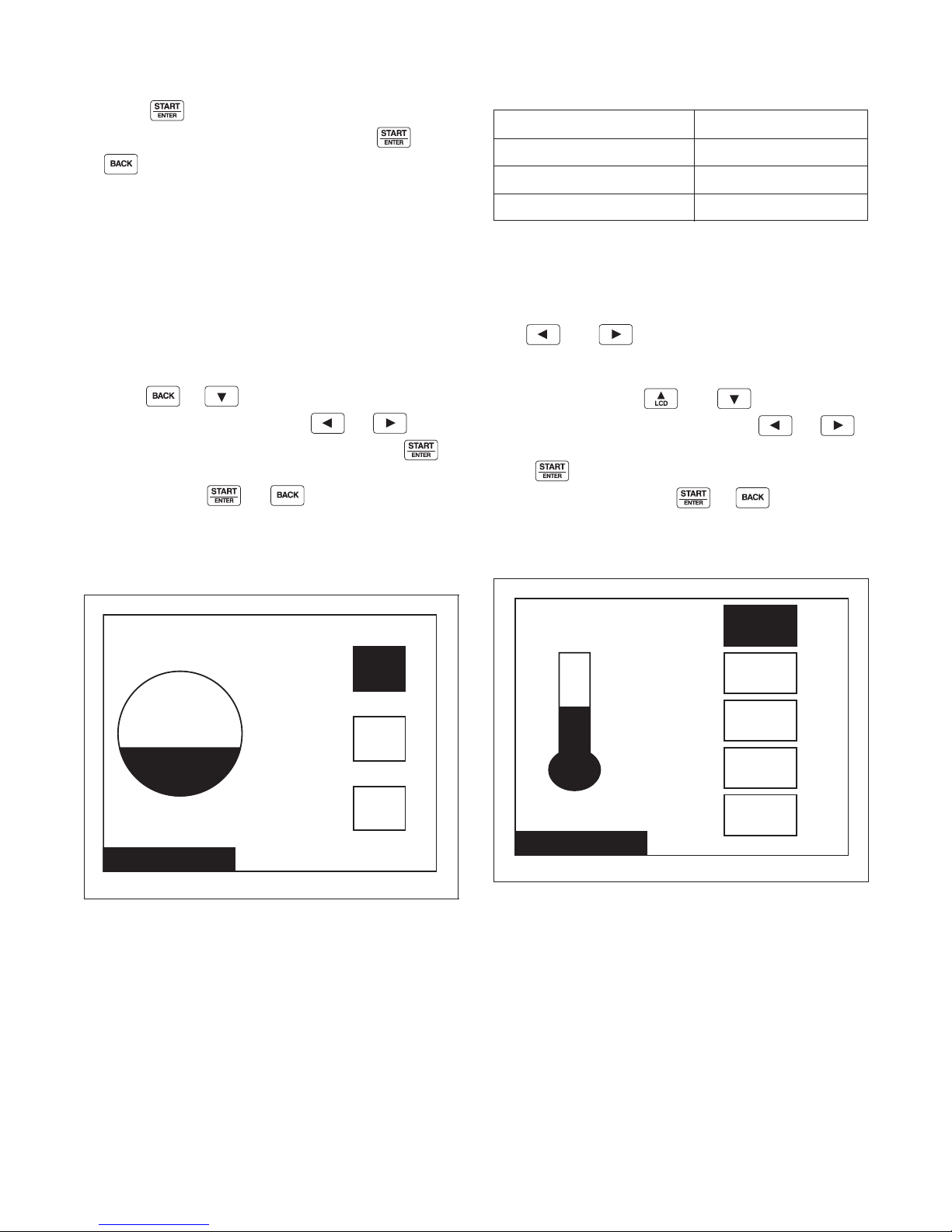
Global Setup
Water Level
Units
High
27
15
Medium
3
Low
Temperature
Off
Fahrenheit
Temp Controlled Fill
110
Cooldown
140
Hot
100
TempWarm
35
Cold
F
˚
F
˚
F
˚
F
˚
Press the keypad to return to Global Setup
Menu. If no changes were made, press the
or keypad to return to Global Setup Menu.
The control’s Clock will automatically adjust for leapyear. The control may be programmed for automatic
daylight saving adjustment. If the Daylight Saving
option is disabled, no adjustment takes place. If it is
enabled, on the second Sunday in March, the time will
spring forward from 1:00 AM to 2:00:00 AM. On the
first Sunday in November, the time falls back from
2:00:00 AM to 1:00:00 AM.
Daylight Saving can be enabled or disabled by moving
highlighted box to Daylight Saving and
pressing or to Yes or No. The Save
Changes Menu will display. Use or to
move highlighted box to “Yes” or “No”. Press
keypad to return to Global Setup Menu. If no changes
were made, press or keypad to return to
Global Setup Menu. The factory-default value for
daylights saving is enabled.
Water Level Menu
Water Level Value
Low (20%) 01-10
Medium (30%) 11-20
High (40%) 21-30
Ta bl e 3
The water level settings will apply to all cycles that are
programmed using low, medium or high in the water
level setting.
The and keypads are used to move the
highlighted box through the different items in the
menu. Once the item is highlighted, the value can be
changed by using the and keypads. The
Save Changes Menu will display. Use or
to move highlighted box to “Yes” or “No”.
Press keypad to return to Global menu. If no
changes were made, press or keypad to
return to Global Setup Menu.
Temperature Menu
Figure 43
The Water Level Menu sets the different global water
level settings. The value of the water level is a
percentage of the machine maximum water level,
which is in 30 equal parts or levels. In the 30 different
settings, the image will contain three different regions.
The regions are found in Tab le 3 .
40
© Copyright, Alliance Laundry Systems LLC – DO NOT COPY or TRANSMIT
PHM1039R
PHM1040R
Figure 44
The Temperature Menu sets the different global
temperature settings. The unit of the temperature can
be changed between Fahrenheit and Celsius. The
temperature settings will apply to all cycles that are
programmed using COLD, WARM, and HOT in the
temperature setting. The Temperature Controlled Fill
option will allow the user, with a temperature sensor
present, to chose whether to run the machine with
Temperature controlled Fill On or Off.
F8434101
Page 43
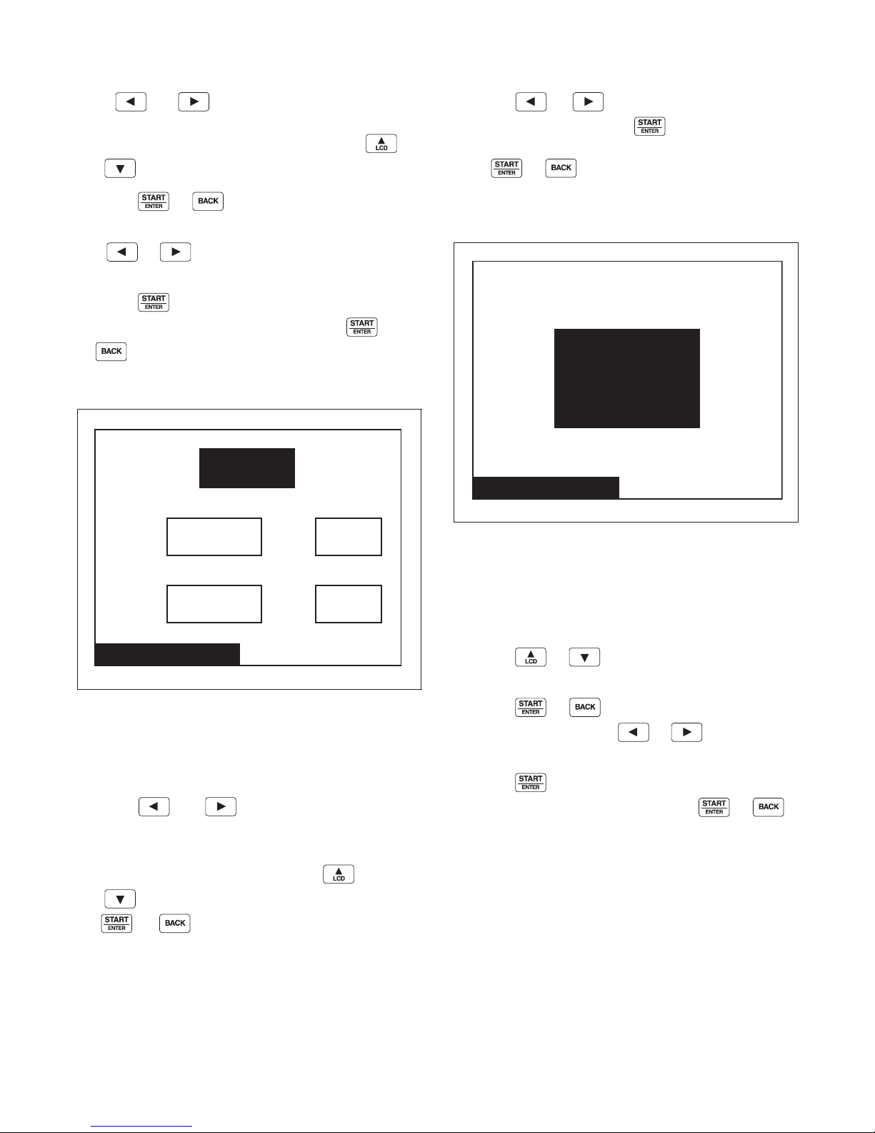
Global Setup
Audio / Ext Signal
On
Low
Key Pad
End of Segment / Cycle
Volume:
5
s
Time:
No
External Signal
Enable:
5
s
Time:
Balance Retry
3
Number of Retries
Press and keypads to move the
highlighted box through the different items in the
menu. Once the item is highlighted, press the
and keypads to change the values.
Press the or keypad to jump to the Save
Changes Menu.
Use or to move highlighted box to “Yes”
or “No”.
Press the keypad to return to Global Setup
Menu. If no changes were made, press the
or keypad to return to Global Setup Menu.
Audio Menu
Press the or keypad to move highlighted
box to “Yes” or “No”. Press keypad to return to
Global Setup Menu. If no changes were made,
press or keypad to return to Global Setup
Menu.
Balance Retry Menu
PHM1042R
Figure 45
The Audio/External Signal Menu sets the audio
options of the keypad audio feedback, the beeper
volume and the External Signal.
Press the and keypads to move the
highlighted box through the different items in the
Audio Menu.
Once the item is highlighted, press the
and keypads to change the value. Press
the or keypad to return to the Save
Changes Menu if changes were made.
PHM1041R
Figure 46
The Balance Retry Menu sets the option of how many
retries the machine will attempt to rebalance a load
before an alarm is set. The user will be able to select a
value from one (1) to seven (7).
Press the or keypad to change number of
balance retries.
Press the or keypad to jump to the Save
Changes Menu. Press the or keypad to
move highlighted box to “Yes” or “No”.
Press the keypad to return to Global Setup
menu. If no changes were made, press or
keypad to return to Global Setup Menu.
F8434101
© Copyright, Alliance Laundry Systems LLC – DO NOT COPY or TRANSMIT
41
Page 44
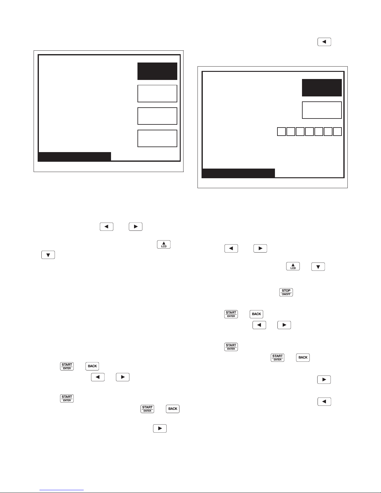
Global Setup
Does the Machine Have
Water Reuse Installed?
Does the Machine Have
Water Recirc Installed?
External Dispenser Pause
Advanced Options
Water Mgmt. (1 of 4)
Off
No
No
No
Water Leak Detection
During Machine Cycle
Number of Cycles Between
Day(s) Occurring
Water Mgmt. (2 of 4)
0
On
S M T W R F S
Water Management Menu
PHM1410R
Figure 47
The Water Management 1 Menu allows the user to set
the water reuse and water recirculation options to Yes
or No. If water reuse option is turned off, the Reuse
Fill Menu will not be displayed during programming
of a Segment. Press the and keypads to
move the highlighted box through the different items
in the Water Management 1 Menu. Press the
or keypad to change selections to “Yes” or
“No”.
The user can set the External Dispenser Pause On or
Off. The control default for this option is “Off”. If
programmed on, the control will wait with a normally
open contact for contact closure to indicate the need
for a pause in cycle operation.
The user can set the Advance Options in the Water
Management Menu to Yes or No. The control default
for this option is “No.” If programmed Yes, the Valves
Option is enabled in the Modify Cycle Fill Step Menu
and enables Modify Cycle General Purpose Signals
Menu during programming of a cycle.
Press the or keypad to jump to the Save
To view Water Management 4 Menu, press
keypad while the “Does the Machine Have Water
Reuse Installed?” textbox is highlighted.
PHM1274R
Figure 48
The Water Management 2 Menu allows the user to
enable or disable the Water Leak Detection During
Machine Cycle parameter. Once Water Leak Detection
is enabled, the Number of Cycles Between and the
Day(s) Occurring parameters can be changed.
Press the and keypads to move the
highlighted box through the parameters of the Water
Management 2 Menu. Press the or
keypads to change the Water Leak Detection During a
Machine Cycle and Number of Cycles Between
parameters’ values. Press the keypad to change
the Day(s) Occurring parameter’s values.
Press the or keypad to jump to the Save
Change Menu. Use or to move
highlighted box to “Yes” or “No”.
Press the to return to Global Setup Menu. If no
changes were made, press or keypad to
return to Global Setup menu.
Changes Menu. Use or to move
highlighted box to “Yes” or “No”.
Press the keypad to return to Global Setup
Menu. If no changes were made, press or
keypad to return to Global Setup menu.
To view Water Management 2 Menu, press
keypad while the “External Dispenser Pause” textbox
is highlighted/
42
© Copyright, Alliance Laundry Systems LLC – DO NOT COPY or TRANSMIT
To view Water Management 3 Menu, press
keypad until the menu is displayed.
To view Water Management 1 Menu, press
keypad while Water Leak Detection During Machine
Cycle textbox is highlighted.
F8434101
Page 45
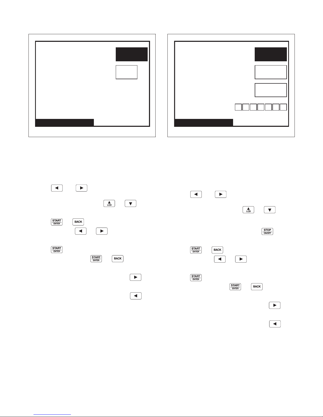
Global Setup
Slow Drain Detection
During Machine Cycle
Slow Drain Adjustment
Water Mgmt. (3 of 4)
0
S
On
Auto Water Leak Detection
Number of Cycles Between
Hour Occurring
Day(s) Occurring
Water Mgmt. (4 of 4)
0
0
On
S M T W R F S
PHM1275R
Figure 49
The Water Management 3 Menu allows the user to
enable or disable the Slow Drain Detection During
Machine Cycle parameter. Once Slow Drain Detection
is enabled, the Slow Drain Adjustment parameter can
be changed.
Press the and keypads to move the
highlighted box through the parameters of the Water
Management 3 Menu. Press the or
keypads to change the values of the parameters.
Press the or keypad to jump to the Save
Change Menu. Use or to move
highlighted box to “Yes” or “No”.
Press the to return to Global Setup Menu. If no
changes were made, press or keypad to
return to Global Setup menu.
To view Water Management 4 Menu, press
keypad until the menu is displayed.
To view Water Management 2 Menu, press
keypad while Slow Drain Detection During Machine
Cycle textbox is highlighted.
PHM1276R
Figure 50
The Water Management 4 Menu allows the user to
enable or disable the Auto-Water Leak Detection
parameter. Once Auto-Water Leak Detection is
enabled, the Number of Cycles Between, Hour
Occurring and Day(s) Occurring parameters can be
changed.
Press the and keypads to move the
highlighted box through the parameters of the Water
Management 4 Menu. Press the or
keypads to change the values of the Auto-Water Leak
Detection, Number of Cycles Between and Hour
Occurring parameters’ values. Press the keypad
to change the value of the Day(s) Occurring parameter.
Press the or keypad to jump to the Save
Change Menu. Use or to move
highlighted box to “Yes” or “No”.
Press the to return to Global Setup Menu. If no
changes were made, press or keypad to
return to Global Setup menu.
To view Water Management 1 Menu, press
keypad until the menu is displayed.
F8434101
© Copyright, Alliance Laundry Systems LLC – DO NOT COPY or TRANSMIT
To view Water Management 3 Menu, press
keypad while Auto-Water Leak Detection textbox is
highlighted.
43
Page 46
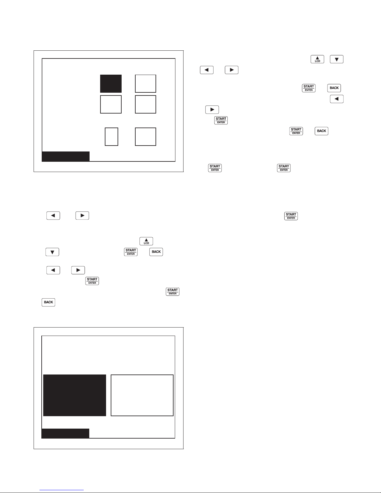
Global Setup
Alarms
mm
Fill
5
ss
hmm
00:
Drain
2 00:
Heat
1 30:
Rapid Advance
Enable the Rapid Advance
Feature During Cycle Operation?
NoYes
Alarms Program Menu
PHM1044R
Figure 51
The Alarms Program Menu is used to set the fill,
drain, and heat alarm times.
The and keypads are used to move the
highlighted box through the different items in the
Alarm Program Menu. Once the item is highlighted,
the value can be changed by using the
and keypads. Pressing the or
keypad will jump to the Save Changes Menu.
Use or to move highlighted box to “Yes”
or “No”. Press the keypad to return to Global
Setup menu. If no changes were made, press the
The Rapid Advance Menu has the option of whether
the user will be able to rapid advance through steps
while the machine is operating. Press the
or keypad to change the selection. All
the keypads have the same effect and will toggle the
selection between on or off. Press the or
keypad to jump to the Save Changes Menu. Use
or to move highlighted box to “Yes” or “No”.
Press keypad to return to Global Setup Menu. If
no changes were made, press the or
keypad to return to Global Setup Menu.
If the Rapid Advance Option is enabled, the user can
advance a running machine cycle with presses of
the keypad. When the keypad is pressed,
the control will immediately show the next cycle step
in the Run Menu but will not change the outputs for a
period of at least five (5) seconds. The user may
advance into any cycle step except the Spray Rinse
Extract and Extract Steps. If the control is executing a
Drain step and the user presses to execute a
Rapid Advance, the control will skip over the Extract
Step. When the cycle is completed, the audit counter,
Total Rapid Advance Cycles is incremented rather
than the Total Machine Cycles audit counter. In
addition this cycle is recorded in the audit list “Last 25
Machine Cycles Completed” and the audit list “Last
10 Machine Cycles Rapid Advanced/Aborted.” Refer
to UniLinc PC and PDA Application User
Instructions for additional information on using a PC/
PDA.
or keypad to return to Global Setup Menu.
Rapid Advance Menu
44
Figure 52
© Copyright, Alliance Laundry Systems LLC – DO NOT COPY or TRANSMIT
In the Run Menu, the total remaining cycle time is
reduced by the corresponding advance step time if
programmed. If the Rapid Advance Option is disabled
preventing a manual Rapid Advance, the user may still
execute a Rapid Advance using the PC/PDA through
the network.
PHM1045R
F8434101
Page 47
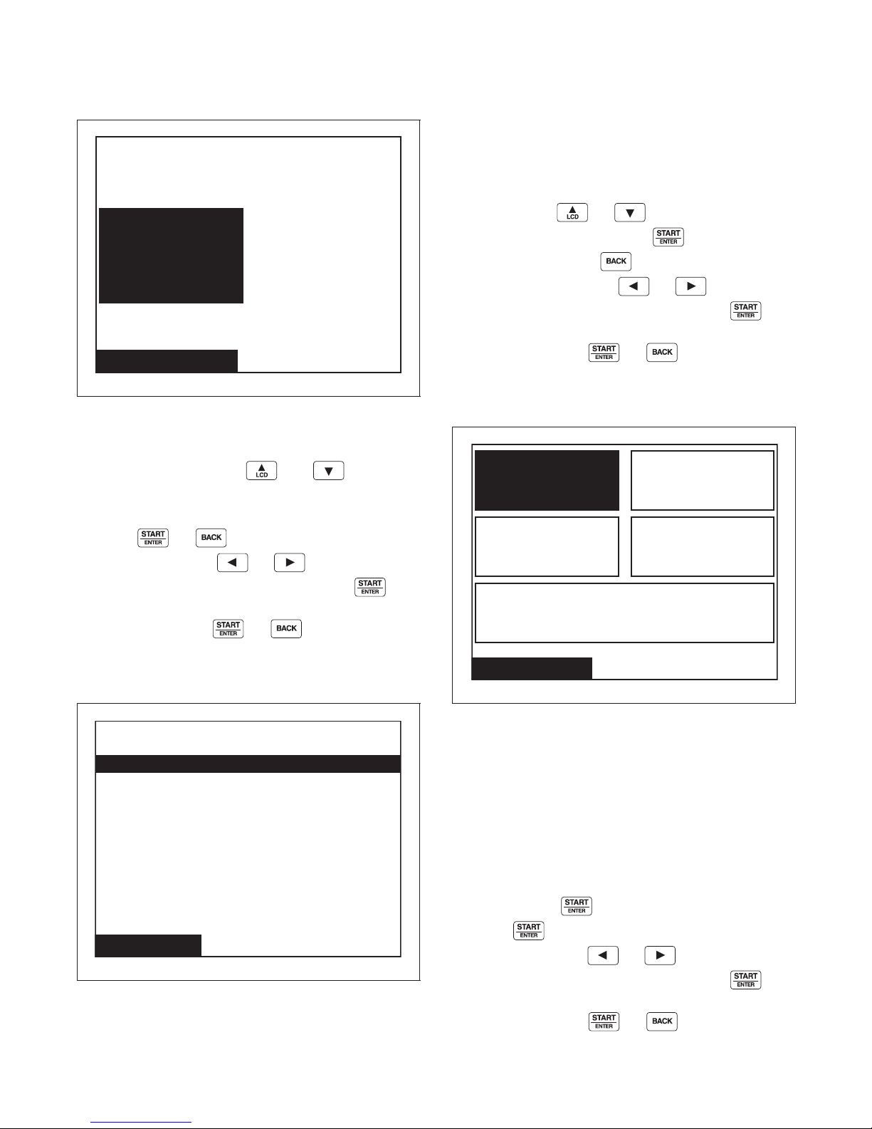
Global Setup
Shakeout Menu
Shake Out Time
Sec40
Banners
Banner #1
Banner #2
Factory Defaults
Water
Temperature Only
Restore All Cycles and Global
Settings to Factory Defaults
Water Level Only
Alarms Only Audio Only
Shakeout Menu
PHM1046R
Figure 53
The Shakeout Menu is used to set the Shakeout time
after the Extract Step. The and keypads
adjust the time. The time can be set from 0-120
seconds in increments of 20 seconds.
The Banners Menu is used to create or modify the
banners that are displayed while the machine is on the
Cycle Menu. The banners are displayed at the top of
the screen.
The banners are created or modified using the String
Edit Mode. Refer to Program Menu, Modify Cycle
section. Use the or keypad to highlight
the different lines and press the keypad to edit
the string. Pressing the keypad will jump to the
Save Changes Menu. Use or to move
highlighted box to “Yes” or “No”. Press the
keypad to return to Global Setup Menu. If no changes
were made, press the or keypad to return
to Global Setup Menu.
Factory Defaults Menu
Press the or keypad to enter the Save
Changes Menu. Press or to move
highlighted box to “Yes” or “No”. Press the
keypad to return to Global Setup Menu. If no changes
were made, press the or keypad to return
to Global Setup Menu.
Banners Menu
PHM1048R
Figure 55
The Factory Defaults Menu is used to set parameters
in the software back to the factory default. Several
parameters can be set individually back to the factory
settings and all Cycles and Global settings can be
restored. The individual parameters that can be set
back to the factory settings are the water level, water
temperature, alarms, and audio settings.
Press the directional keys to navigate through the
screen. Press the keypad to make a selection.
Once the keypad is pressed, Save Changes
Figure 54
F8434101
© Copyright, Alliance Laundry Systems LLC – DO NOT COPY or TRANSMIT
PHM1047R
Screen displays. Use or to move
highlighted box to “Yes” or “No”. Press the
keypad to return to Global Setup menu. If no changes
were made, press the or keypad to return
to Global Setup Menu.
45
Page 48
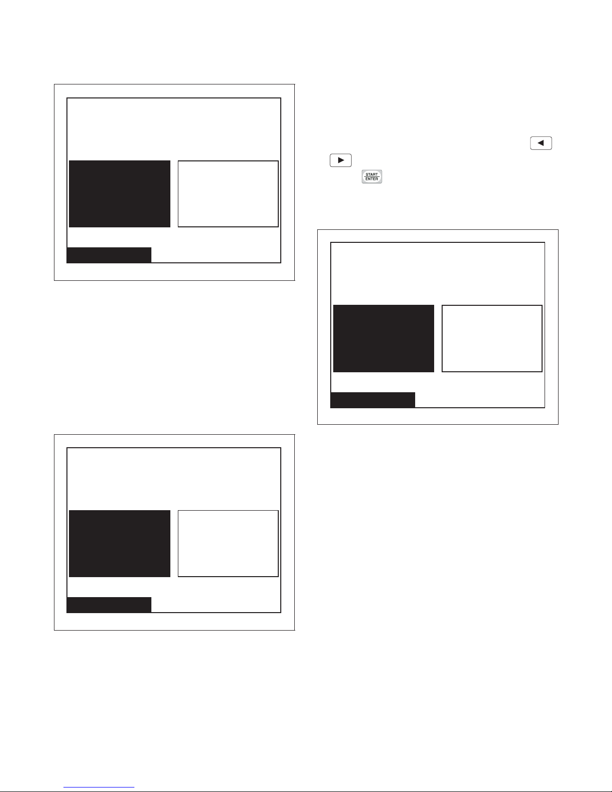
Global Setup
Are you sure you want
to restore water level settings?
Ye sNo
Factory Defaults
Are you sure you want
to restore water temperature
settings?
Ye sNo
Factory Defaults
Are you sure you want
to restore alarms settings?
Ye sNo
Factory Defaults
Water Level Confirmation Menu
PHM1049R
Figure 56
The Water Level Confirmation Menu is used to
confirm that water levels are to be set back to factory
defaults. This screen is displayed when the Water
Level Only option is selected in the Factory Defaults
Menu. Once the confirmation is chosen the display
will jump back to the Factory Defaults Menu. “No” is
selected by default.
The Water Temperature Confirmation Menu is used to
confirm that water temperatures are to be set back to
factory defaults. This screen is displayed when the
Water Temperature Only option is selected in the
Factory Defaults Menu. Once the confirmation is
chosen the display will jump back to the Factory
Defaults Menu. “No” is selected by default. Use
or to move highlighted box to “Yes” or “No”.
Press the keypad to return to Global Setup
Menu.
Alarms Confirmation Menu
Water Temperature Confirmation
Menu
Figure 57
PHM1051R
Figure 58
The Alarms Confirmation Menu is used to confirm
that the alarms are to be set back to factory defaults.
This screen is displayed when the Alarms Only option
is selected in the Factory Defaults Menu. Once the
confirmation is chosen the display will jump back to
the Factory Defaults Menu. “No” is selected by
default.
PHM1050R
46
© Copyright, Alliance Laundry Systems LLC – DO NOT COPY or TRANSMIT
F8434101
Page 49
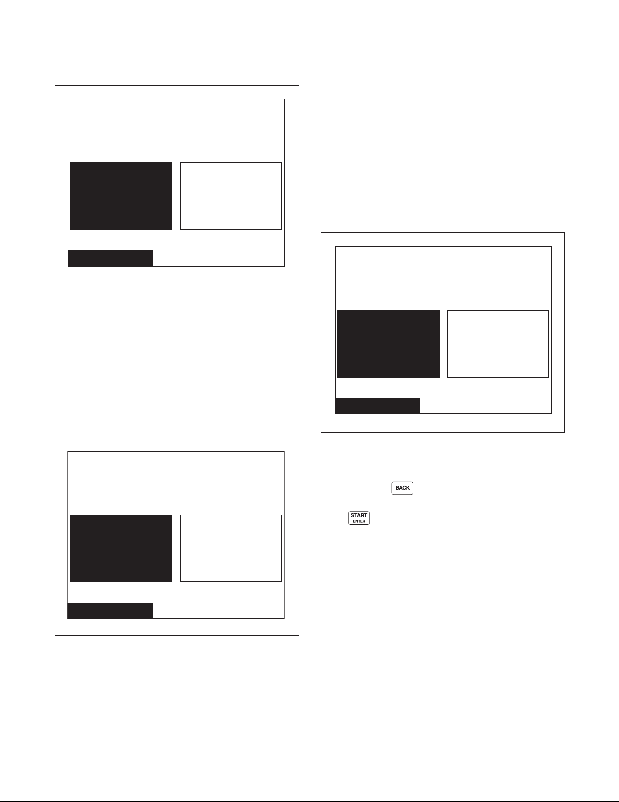
Global Setup
Are you sure you want
to restore audio settings?
Ye sNo
Factory Defaults
Are you sure you want
to restore all cycles and global
settings to factory defaults?
Ye sNo
Factory Defaults
! WARNING !
Restore all cycles and global
settings to factory defaults?
Ye sNo
Factory Defaults
Audio Confirmation Menu
PHM1052R
Figure 59
The Audio Confirmation Menu is used to confirm that
the audio is to be set back to factory defaults. This
screen is displayed when the Audio Only option is
selected in the Factory Defaults Menu. Once the
confirmation is chosen the display will jump back to
the Factory Defaults Menu. “No” is selected by
default.
The Reset All Factory Defaults Confirmation Menu is
used to confirm that the global programming
parameters and Cycle #1-41 are to be set back to
factory defaults. This screen is displayed when the
Restore All Cycles and Global Settings to Factory
Defaults option is selected in the Factory Defaults
Menu. If “No” is selected the display will jump back
to the Factory Defaults Menu. If “Yes” is selected the
display will jump to the Factory Defaults Second
Confirmation Menu. “No” is selected by default.
Factory Defaults Second
Confirmation Menu
Reset All Factory Defaults
Confirmation Menu
Figure 60
PHM1054R
Figure 61
The Factory Defaults Second Confirmation Menu is to
ensure that the factory defaults do not get accidentally
reset. Press the keypad to abort and the display
will then show the Factory Defaults Menu.
Press keypad to select “Yes” or “No”.
Selecting “Yes” will restore all the factory settings and
take the user back to the Global Settings Menu.
Selecting “No” will take the user back to the Factory
Defaults Menu.
PHM1053R
F8434101
© Copyright, Alliance Laundry Systems LLC – DO NOT COPY or TRANSMIT
47
Page 50
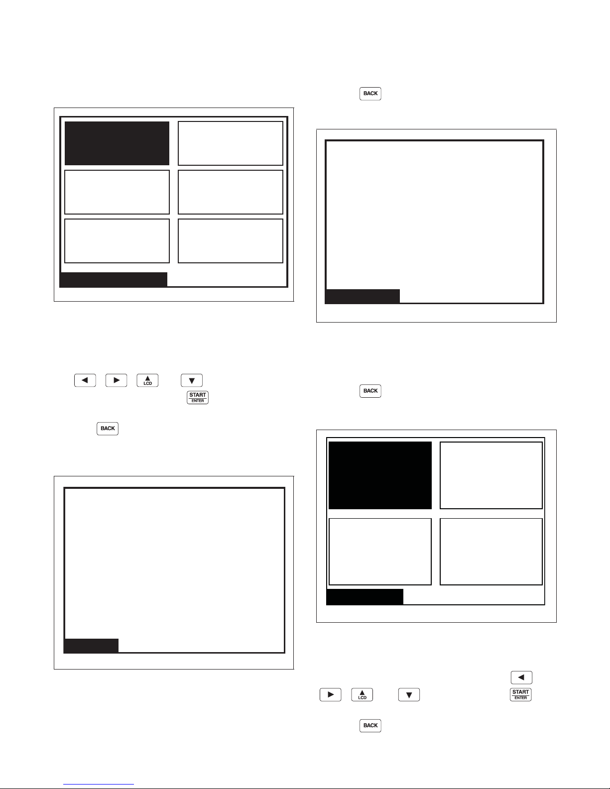
Diagnostic
Machine ID
Drive ID
Drive Alarms
Test
Water Leak
Detection
Alarms
Diagnostic Menu
Drive ID
Drive Type
Drive SW
Drive Parameter Set
Drive DC Bus
5HP 480V
1
1
294
Drive Alarms
Drive Alarms
Last Drive Error:
Drive SPI
DC Bus
No Tach
Locked Rotor
Shorted IGHT
IPM Overtemp
Invalid Parameter Set
Max Current Exceeded
Current Sensor
Drive SPI Error
Count 1
Count 0
Count 0
Count 0
Count 0
Count 0
Count 0
Count 0
Count 0
Test Menu
Inputs Outputs
Factory Valve
Purge
Drive Test
Test Cycle
Diagnostic Menu
PHM1411R
Figure 62
The Diagnostic Menu contains Test, Water Leak
Detection, Alarms, Machine ID, Drive ID and Drive
Alarms. The menus contain specific diagnostic
information and manufacturing data for the machine.
The and keypads position
the highlighted box. Press the keypad to select
the menu choice.
Press the keypad while in the Diagnostic Menu
to return to System Menu.
Press the keypad to return to the Test Menu.
Drive Alarms Menu
PHM1492R
Figure 64
The Drive Alarms Menu is used to display the status
of the Last Drive Error and the error counts of the
drive errors.
Press the keypad to return to the Test Menu.
Test Menu
Drive ID Menu
The Drive ID Menu is used to display the drive type,
drive software version number, drive parameter set
version number, and DC bus value.
48
Figure 63
© Copyright, Alliance Laundry Systems LLC – DO NOT COPY or TRANSMIT
PHM1482R
Figure 65
PHM1481R
The Test Menu provides features for manufacturing
and customer service testing. The highlighted box is
moved horizontally and vertically using the
and keypads. Press the
keypad to select the menu choice.
Press the keypad to return to Diagnostic Menu.
F8434101
Page 51
Test Cycle
Diagnostic
STEP Test Cycle Step
Keypad Test Step FEC and Output Board S/W
1
Door and Lock
2
Test Step
Display Test Step “Press Any Keypad To
3
Display Test Step #1 Screen is blank Keypress
4
Display Test Step #2 Horizontal Bars Keypress
5
Display Test Step #3 Horizontal Bars (inverted) Keypress
6
Display Test Step #4 Screen is gray Keypress
7
Hot Fill to Low Level “Hot Fill To Low” Keypress All outputs turned off when
8
Cold Fill to Low Level “Cold Fill To Low” Keypress All outputs turned off when
9
Warm Fill to Low Level “Warm Fill To Low” Keypress when Low
10
Warm Fill to High Level “Warm Fill to High” Keypress when High
11
External Supply #1
12
Wash Speed Agitate
External Supply #2
13
Wash Speed Agitate
External Supply #3
14
Wash Speed Agitate
External Supply #4
15
Wash Speed Agitate
External Supply #5
16
Wash Speed Agitate
External Supply #6
17
Wash Speed Agitate
External Supply #7
18
Wash Speed Agitate
External Supply #8
19
Wash Speed Agitate
Int Supply #1
20
Wash Speed Agitate
Int Supply #2
21
Wash Speed Agitate
Displayed
Description
STEP ADVANCE COMMENTS
Advance after all keypads
versions and “Press Each
depressed.
Keypad To Advance”
“Door and Lock Status”
Keypress
Advance Through Screen
Test”
Level is reached
Level is reached
“External Supply #1” Keypress
“External Supply #2” Keypress
“External Supply #3” Keypress
“External Supply #4” Keypress
“External Supply #5” Keypress
“External Supply #6” Keypress
“External Supply #7” Keypress
“External Supply #8” Keypress
“Internal Supply #1” Keypress or
30 seconds
“Internal Supply #2” Keypress or
30 seconds
Table 4 (Continued)
Low Level reached
Low Level reached
All outputs turned off when
Low Level reached
All outputs turned off when
High Level reached
F8434101
© Copyright, Alliance Laundry Systems LLC – DO NOT COPY or TRANSMIT
49
Page 52

Diagnostic
Table 4 (Continued)
STEP Test Cycle Step Displayed Description STEP ADVANCE COMMENTS
Int Supply #3
22
Wash Speed Agitate
Internal Supply #4
23
Wash Speed Agitate
Warm Fill to Overflow
Reduced Wash Speed
24
“Internal Supply #3” Keypress or
30 seconds
“Internal Supply #4” Keypress
or 30 seconds
“Cold Fill To Overflow” Keypress
Agitate
Heat water to 110F
Reduced Wash Speed
25*
“Heat Water to 110F” Keypress All outputs turned off when
temperature reached.
Agitate
Reduced Wash Speed
Forward with no agitation
26
“Reduced Wash Speed” Keypress
action.
Wash Speed Forward
27
with no agitation action.
Wash Speed Reverse with
28
no agitation action.
Drain
29
Distribution Speed
Extract Speed #1
30
“very low”
Extract Speed #2
31
“low”
Extract Speed #3
32
“medium”
Extract Speed #4
33
“high”
Extract Speed #5
34
“very high”
Extract Speed #6
35
“ultra high”
Audio Signal “Audio Signal” Keypress
36
“Wash Speed Forward” Keypress
“Wash Speed Reverse” Keypress
“Drain” Keypress when empty
“Extract Speed 1” Keypress
“Extract Speed 2” Keypress
“Extract Speed 3” Keypress
“Extract Speed 4” Keypress
“Extract Speed 5” Keypress
“Extract Speed 6” Keypress
or 5 seconds
Step skipped if Global
Audio Signal and Global
External Signal is disabled.
Coast Time “Coast”
37
* Step is skipped if no heater in machine.
50
© Copyright, Alliance Laundry Systems LLC – DO NOT COPY or TRANSMIT
Tab le 4
F8434101
Page 53
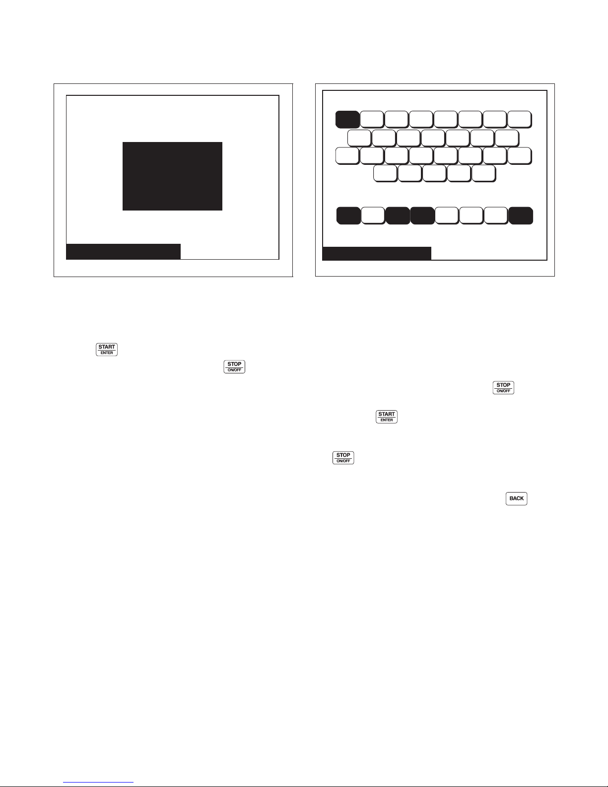
Diagnostic
Factory Valve Purge
Press START
to Begin
FACTORY VALVE PURGE
Inputs Outputs
Outputs:
Inputs:
Temp. 75 F RPM: 0
RUNNING
S1 S2 S3 S4 AX1 HF CF SP1
HS CS RFA RFB AX3 RDB AX5
ES4 ES5 ES6 ES7 ES8
DR PAUS FSW PSW WL TS OSW DL
DN HT DR AX2 AX4 ES1 ES2 ES3
Factory Valve Purge Menu
PHM1057R
Figure 66
The Factory Valve Purge Menu is used to allow the
factory to purge all the valves inside the machine after
the machine has been manufactured and tested.
Press the keypad to activate the step. The step
will run for five (5) minutes unless the keypad is
pressed.
Inputs Outputs Menu
PHM1414R
Figure 67
When the Inputs Outputs Menu is accessed through
the Diagnostic Menu, the user can change outputs. The
Close Door Menu will come up if the door is not
closed. The user can scroll through the outputs using
any of the arrow keys, the cursor is indicated by
flashing the active output on the screen. The user must
“setup” the outputs to be turned on. The keypad
is used to toggle individual outputs to be turned on or
off. After the keypad is pressed the control will
turn the selected outputs on and display the text
“RUNNING”. The outputs cannot be toggled until
the keypad is pressed. The text “RUNNING” is
no longer displayed. The screen will still show the
selected outputs on the screen and the user can again
toggle outputs to be turned on or off. If the
keypad is pressed at any time during this test, the
control will turn off all outputs if the test is running or
return to the previous screen if the test is not running.
F8434101
© Copyright, Alliance Laundry Systems LLC – DO NOT COPY or TRANSMIT
51
Page 54
Diagnostic
Abbreviations for the Inputs and Outputs are defined
in the following table:
Outputs Outputs
AX1 Auxiliary Fill or Internal Supply 5 RFB Reuse Fill B
AX2 Unused S1 Internal Supply 1
AX3 Recirculation or Reuse Drain A S2 Internal Supply 2
AX4 External Signal (Optional Audio) S3 Internal Supply 3
AX5 Reuse Wash Drain S4 Internal Supply 4
CF Cold Fill SP1 VFD Power
CS Cold Spray
DN Drain Inputs
DR Door Unlock BAL Unused
ES1 External Supply 1 DL Door Lock
ES2 External Supply 2 DR Door
ES3 External Supply 3 FSW Frame Balance Switch
ES4 External Supply 4 OSW Unused
ES5 External Supply 5 PAUS External Dispenser Pause A and/or B
ES6 External Supply 6 PSW Low Level Pressure Switch
ES7 External Supply 7 TS Thermostat (Temp Satisfied)
ES8 External Supply 8 WL Water Level (Level Satisfied)
HF Hot Fill Temp Temperature Sensor Value
HS Hot Spray RPM Revolutions per Minute
HT Heater
RDB Reuse Drain B
RFA Reuse Fill A
Tab le 5
52
© Copyright, Alliance Laundry Systems LLC – DO NOT COPY or TRANSMIT
F8434101
Page 55
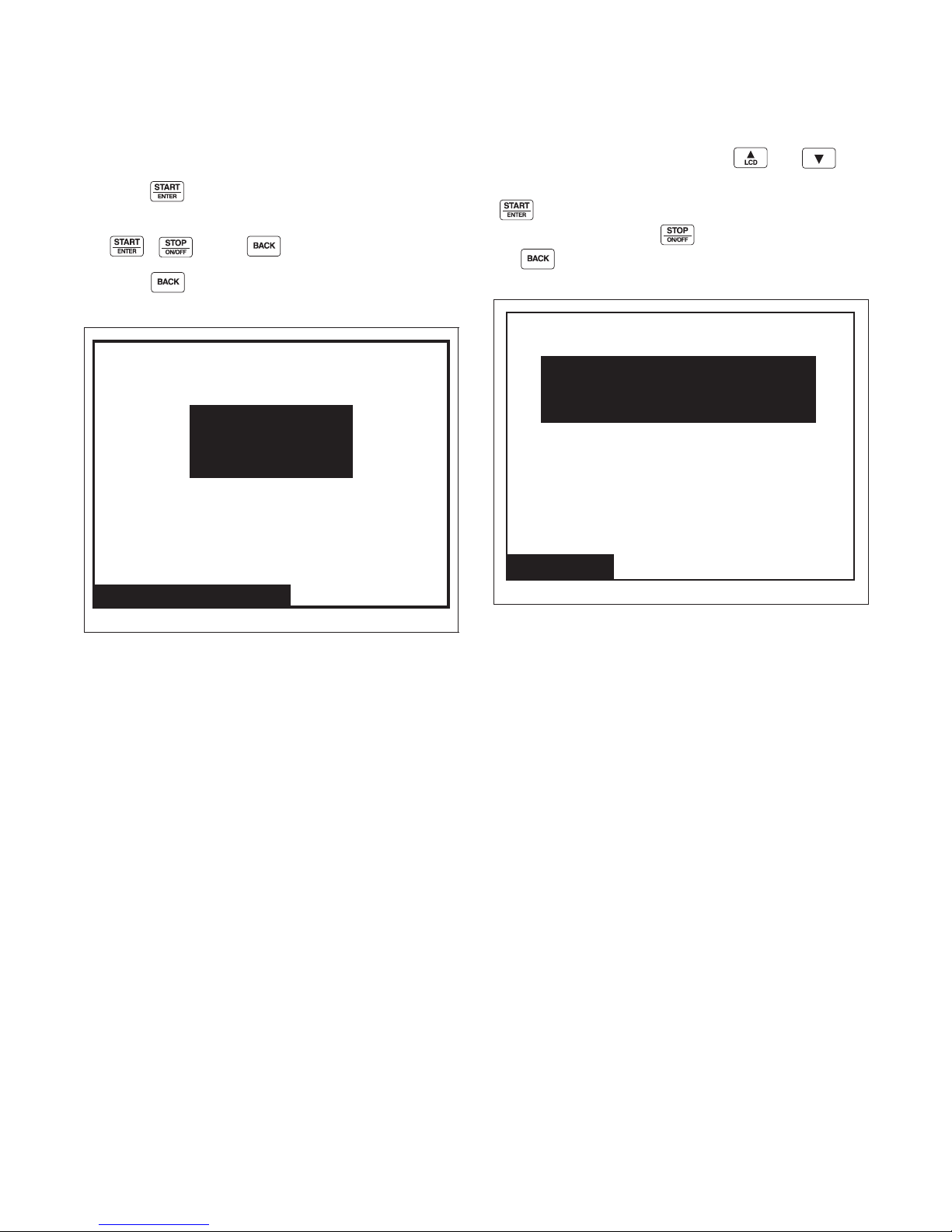
Diagnostic
Press START
to Begin
WATER LEAK DETECTION
Test Finished, Result:
PASS
Water Leak Detection
Drive Test
Reduced Agitate Forward
Select Drive Command
Then Press START to Begin
RPM: 0 DC Bus: 0
Water Leak Detection Diagnostic
The Water Leak Detection menu is used to display the
result of the Water Leak Detection test.
Press the keypad to initiate the test.
To end the test before it is complete, press either
the , or the keypad.
Press the keypad to return to the Diagnostic
Menu or the Run Diagnostic Menu.
Drive Test
The Drive Test Menu is used to check and display
drive and motor functionality. The and
keypads select the motor speed and direction. Press the
keypad to initiate the test. To end the test before
it is complete, press the keypad. Press
the keypad to return the Diagnostic Menu or the
Run Diagnostic Menu.
Figure 68
PHM1207R
PHM1480R
Figure 69
F8434101
© Copyright, Alliance Laundry Systems LLC – DO NOT COPY or TRANSMIT
53
Page 56
Diagnostic
ALARM COUNTS
C01: S02 Unbalance Load Error
C01: S04 Fill Error
C23: S10 Door Error
C02: S15 Unbalance Load Error
C11: S04 Unbalance Load Error
C39: S11 Drive SPI Error
11/05 03:34
10/10 13:56
08/25 10:41
04/25 21:30
01/20 09:25
01/19 02:45
Alarms (1 of 3)
Alarms (2 of 3)
ALARM COUNTS
Lock
Door
Drain
Slow Drain
Water Leak
Fill
Frame Balance
Open
Count 1
Count 0
Count 0
Count 0
Count 0
Count 1
Count 1
Count 0
Alarms (3 of 3)
ALARM COUNTS
Short
SPI
Unbalance
Heat
Level
IR
Network
Count 0
Count 0
Count 3
Count 0
Count 0
Count 1
Count 1
Alarms
Figure 70
PHM1416R
The Alarms Menu contains several screens of
information. On the first screen, Alarms (1 of 3), the
eight most recent alarms will contain Cycle Number,
Segment Number, Step, Alarm Type, and the Date/
Time of the Alarm.
The second screen, Alarms (2 of 3), alarm counts list 1
through 8. Alarm counts consist of how many times a
specific alarm has occurred.
The third screen, Alarms (3 of 3), is a continuation of
the alarm counts 9 through 15.
Press the or keypad to navigate to the
different screens in the Alarms Menu. Press the
keypad to go from screen 1 to screen 3. The actual
menus are informational only and cannot be navigated.
Press the keypad to return to display to
Diagnostic Menu or the Run Diagnostic Menu.
54
PHM1417R
Figure 71
Figure 72
© Copyright, Alliance Laundry Systems LLC – DO NOT COPY or TRANSMIT
PHM1418R
F8434101
Page 57

Diagnostic
Machine ID
Model: UWN065T4VXU1001
Serial #: 01234567890
Install Date: 10/12/2011
Machine Type: SL65
Control SN: 6440091
Front End SW: 1
Display SW: 1
Output SW: 3
Trim Value:
Node Number: 250
2
Machine Identification
Figure 73
The Machine ID Menu provides several different types
of manufacturing and machine information that can be
useful to the user, chemical supplier, and technician.
The Machine ID Menu cannot be navigated. Pressing
the keypad will return to Diagnostic Menu or
the Run Diagnostic Menu.
Machine Errors
The control displays and logs errors as they occur.
When the control senses the error condition, the audit
counter for that error increases by one. The control
saves the time and date of the last eight (8) errors
which have occurred. Following is a list of possible
errors:
Door Lock Error
If the control is in Door Locking Mode attempting to
lock the door and after ten (10) seconds, the control
will abort the machine cycle, display the Cycle
Aborted Error Menu and record and count the Door
Lock Errors audit counter. The control saves the error
type, cycle, segment and step in which it happened and
the date and the time on the Alarms (1 of 3) Menu.
View “Lock” on the Alarms (2 of 3) Menu for the total
error count. The audio signal will also be turned on for
the error condition. The Cycle Aborted Error Menu is
displayed with the Alarm on until the appropriate user
input occurs. The machine cycle is aborted and the
user is only given the option of clearing the Cycle
Aborted Error Menu and returning to the Cycle Menu.
F8434101
© Copyright, Alliance Laundry Systems LLC – DO NOT COPY or TRANSMIT
Door Open Error
If the control senses an open loading door during a
cycle, the control will abort the machine cycle, display
the Cycle Aborted Error Menu and record and count
the Door Open Errors audit counter. The control saves
the error type, cycle, segment and step in which it
happened and the date and the time on the Alarms (1
of 3) Menu. View “Door” on the Alarms (2 of 3) Menu
for the total error count. The audio signal will also be
turned on for the error condition. The Cycle Aborted
Error Menu is displayed with the Alarm on until the
appropriate user input occurs. The machine cycle is
aborted and the user is only given the option of
clearing the Cycle Aborted Error Menu and returning
to the Cycle Menu.
PHM1490R
Drain Alarm Error
When the Drain Alarm time is exceeded, the control
will stop the cycle, display the Cycle Stopped Error
Menu and count and store the Total Drain Errors audit
counter. The control saves the error type, cycle,
segment and step in which it happened and the date
and the time on the Alarms (1 of 3) Menu. View
“Drain” on the Alarms (2 of 3) Menu for the total error
count. The audio signal will also be turned on for the
error condition. The Cycle Stopped Error Menu is
displayed alternating with the Run Menu (3 seconds
Error Menu/3 seconds Run Menu) with the Alarm on
until the appropriate user input occurs. The user can
continue or abort the machine cycle.
Fill Alarm Error
When the Fill Alarm time is exceeded, the control will
stop the cycle and display the Cycle Stopped Error
Menu and count and store the Total Fill Errors audit
counter. The control saves the error type, cycle,
segment and step in which it happened, the date and
the time on the Alarms (1 of 3) Menu. View “Fill” on
the Alarms (2 of 3) Menu for the total error count. The
audio signal will also be turned on for the error
condition. The Cycle Stopped Error Menu is displayed
alternating with the Run Menu (3 seconds Error Menu/
3 seconds Run Menu) with the Alarm on until the
appropriate user input occurs. The user is given the
option of continuing or stopping the machine cycle.
55
Page 58

Diagnostic
Frame Balance Switch Error
If the control detects a Frame Balance Switch error
during a cycle, the control will abort the machine
cycle, display the Cycle Aborted Error Menu and
count and record the Frame Balance Switch Errors
audit counter. The control saves the error type, cycle,
segment and step in which it happened and the date
and the time on the Alarms (1 of 3) Menu. View
“Frame Balance” on the Alarms (2 of 3) Menu for the
total error count. The audio signal will also be turned
on for the error condition. The Cycle Aborted Error
Menu is displayed with the Alarm on until the
appropriate user input occurs. The machine cycle is
aborted and the user is only given the option of
powering down the machine to service the Frame
Balance Switch error condition.
Open Temperature Sensor Error
If the control senses a temperature less than 5 F in a
machine equipped with a temperature sensor, the
control will abort the machine cycle, display the Cycle
Aborted Error Menu and record and count the Open
Thermistor Errors audit counter. The control saves the
error type, cycle, segment and step in which it
happened and the date and the time on the Alarms (1
of 3) Menu. View “Open” on the Alarms (2 of 3)
Menu for the total error count. The audio signal will
also be turned on for the error condition. The Cycle
Aborted Error Menu is displayed with the Alarm on
until the appropriate user input occurs. The machine
cycle is aborted and the user is only given the option
of clearing the Cycle Aborted Error Menu and
returning to the Cycle Menu.
Shorted Temperature Sensor Error
If the control senses a temperature greater than 220 F
in a machine equipped with a temperature sensor, the
control will abort the machine cycle, display the Cycle
Aborted Error Menu and increment the Shorted
Thermistor Errors audit counter. The control saves the
error type, cycle, segment and step in which it
happened and the date and the time on the Alarms (1
of 3) Menu. View “Short” on the Alarms (3 of 3)
Menu for the total error count. The audio signal will
also be turned on for the error condition. The Cycle
Aborted Error Menu is displayed with the Alarm on
until the appropriate user input occurs. The machine
cycle is aborted and the user is only given the option
of clearing the Cycle Aborted Error Menu and
returning to the Cycle Menu.
SPI Error
If the control is unable to communicate with the
Output Board the control will abort the machine cycle,
display the Cycle Aborted Error Menu and increment
the SPI Errors audit counter. The control saves the
error type, cycle, segment and step in which it
happened and the date and the time on the Alarms (1
of 3) Menu. View “SPI” on the Alarms (3 of 3) Menu
for the total error count. The audio signal will also be
turned on for the error condition. The Cycle Aborted
Error Menu is displayed with the Alarm on until the
appropriate user input occurs. The machine cycle is
aborted and the user is only given the option of
clearing the Cycle Aborted Error Menu and returning
to the Cycle Menu.
Unbalance Error
If the control detects an unbalanced load during a
cycle, the control will run the subsequent Spray Rinse
Extract and Extract steps but only at a reduced speed
and will continue the machine cycle. When the
machine cycle is completed, the control will not
display an error but will increment the Unbalance
Errors audit counter. The control saves the error type,
cycle, segment and step in which it happened and the
date and the time on the Alarms (1 of 3) Menu. The
machine cycle has already ended and the user is only
given the option of unlocking/opening the door and
returning to the Cycle Menu. View “Unbalance” on
the Alarms (3 of 3) Menu for the total error count.
Heat Alarm Error
When the Heat Alarm time is exceeded, the control
will stop the cycle, display the Cycle Stopped Error
Menu and count and record the Total Water Heater
Errors audit counter. The control saves the error type,
cycle, segment and step in which it happened and the
date and the time on the Alarms (1 of 3) Menu. The
audio signal will also be turned on for the error
condition. The Cycle Stopped Error Menu is displayed
alternating with the Run Menu (3 seconds Error Menu/
3 seconds Run Menu) with the Alarm on until the
appropriate user input occurs. The user can continue or
abort the machine cycle. View “Heat” on the Alarms
(3 of 3) Menu for the total error count.
56
© Copyright, Alliance Laundry Systems LLC – DO NOT COPY or TRANSMIT
F8434101
Page 59
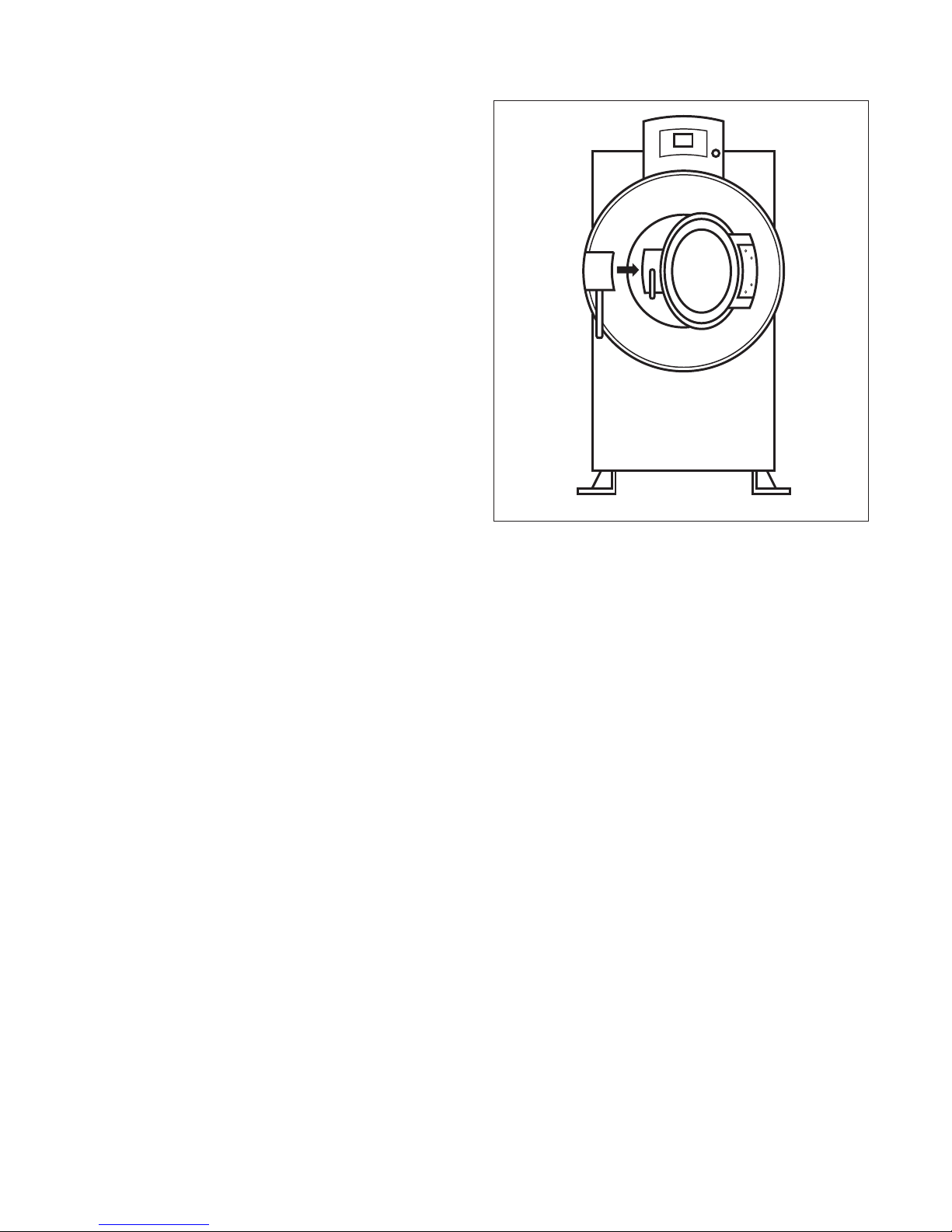
Water Level Sensor Error
Water Leak
Detected:
Fill Valve
If the control senses a High Water Level from the
analog Water Level Sensor during an Extract cycle
step, the control will abort the machine cycle, display
the Cycle Aborted Error Menu, and record and count
the Water Level Sensor Errors audit counter. The
control saves the error type, cycle, segment and step in
which it happened and the date and the time on the
Alarms (1 of 3) Menu. View “Level” on the Alarms (3
of 3) Menu for the total error count. The audio signal
will also be turned on for the error condition. The
Cycle Aborted Error Menu is displayed with the
Alarm on until the appropriate user input occurs. The
machine cycle is aborted and the user is only given the
option of clearing the Cycle Aborted Error Menu and
returning to the Cycle Menu.
IR Communications Error
These errors may occur during IR communications.
When an error occurs, the display shows the
Communication Error Menu. The display on the frontend control will indicate the error by displaying a table
with the Error type. The Error Menu is automatically
cleared from the display after three (3) seconds. When
a PDA error occurs, the audit counter Total Bad IR
Communications is increased by one and the hour and
date of the event. The error code is saved. This error is
not saved on the Alarms (1 of 3) Menu. View “IR” on
the Alarms (3 of 3) Menu for the total error count.
Network Communications Error
These errors may occur during network
communications. When an error occurs, the audit
Counter Total Bad Network is increased by one and
the hour, date, and month of the error. The error code
is saved. This error is not saved on the Alarms (1 of 3)
Menu. View “Network” on the Alarms (3 of 3) Menu
for the total error count.
Water Leak Detection Error
If the control detects a water leak or related problem,
the control will display a Water Leak Detection Error
as described below.
• Water Leak Detection During a Machine Cycle
If the Water Leak Detection Error occurs during a
machine cycle, the control will record the error
and display the message “Water Leak Detected:
Drain Valve” or “Water Leak Detected: Fill
Valve” at the end of the cycle on the Unlock/
Open Door Menu. The control saves the error
type as well as the cycle, segment, step, date and
time in which the error occurred. The error is
added to a queue that holds the last 8 machine
errors.
Diagnostic
PHM1443R
Figure 74
• Water Leak Detection Error During a Diagnostic
Test
If the Water Leak Detection Error occurs during
the Water Leak Detection Diagnostic Test, the
control will record the error and display the
message “FAIL: Drain Valve” or “FAIL: Fill
Valve.” The control saves the error type as well
as the date and time on which the error occurred.
The error is added to a queue that holds the last 8
machine errors.
• Water Leak Detection Error During Auto-Water
Leak Detection
If the Water Leak Detection Error occurs during
the Auto Water Leak Detection, the control will
record the error and display the message “FAIL:
Drain Valve” or “FAIL: Fill Valve.” After the test
is complete, the control will continue to display
the “FAIL: Drain Valve” or “FAIL: Fill Valve.”
message until any keypad is pressed, at which
point the control will return to the Cycle Menu.
The control saves the error type as well as the
date and time on which the error occurred. The
error is added to a queue that holds the last 8
machine errors.
F8434101
© Copyright, Alliance Laundry Systems LLC – DO NOT COPY or TRANSMIT
57
Page 60
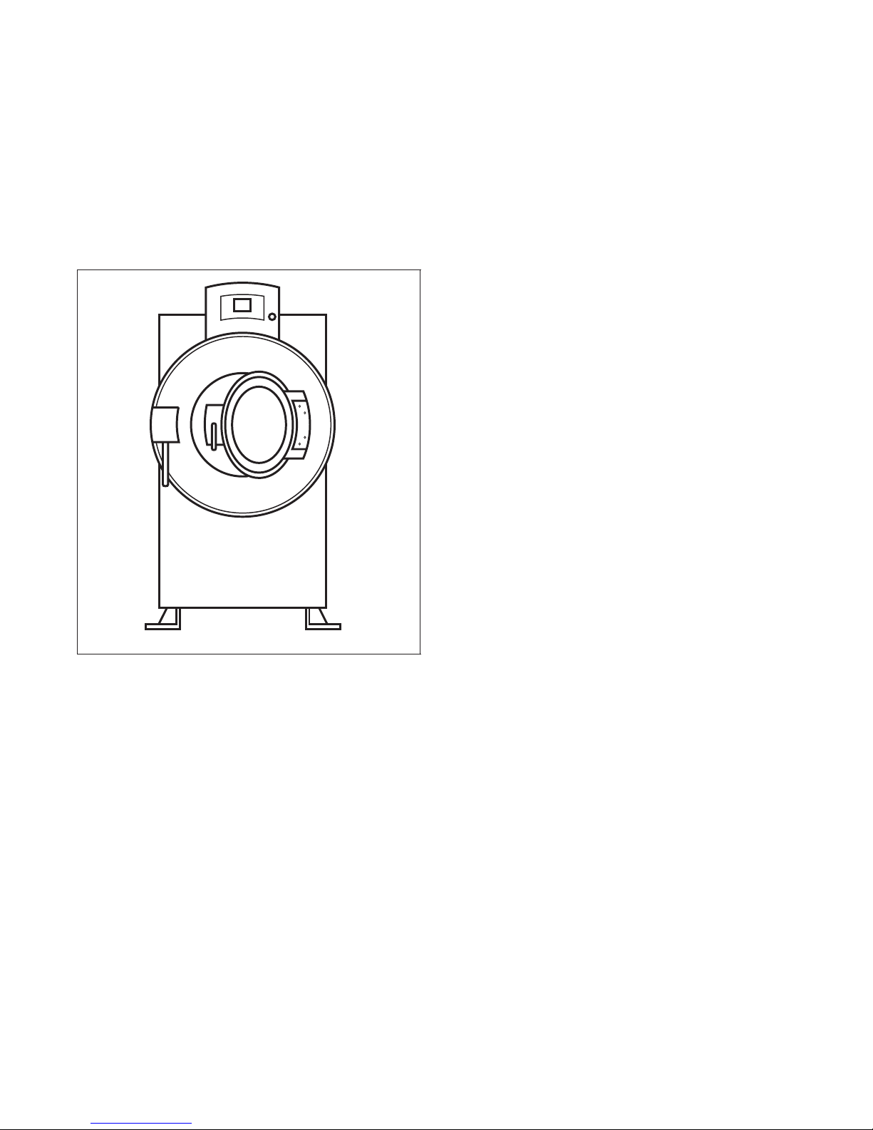
Diagnostic
Slow Drain
Detected
Slow Drain Detected During A Machine
Cycle Error
If the Slow Drain Error occurs during a machine cycle,
the control will record the error and display the
message “Slow Drain Detected” on the Door Unlock
menu. The control saves the error type as well as the
cycle, segment, step, date and time in which the error
occurred. The error is added to a queue that holds the
last 8 machine errors.
DC Bus Error
If the control detects a DC Bus error during a cycle,
the control will abort the cycle, display the Cycle
Aborted Error Menu, and record and count the DC Bus
audit counter. The control saves the error type, cycle,
segment and step in which it happened and the date
and time on the Alarms (1 of 3) Menu. The audio
signal will also be turned on for the error condition.
The Cycle Aborted Error Menu is displayed with the
alarm on until the appropriate user input occurs.
No Tachometer Error
If the control detects a No Tachometer error during a
cycle, the control will abort the cycle, display the
Cycle Aborted Error Menu, and record and count the
No Tachometer audit counter. The control saves the
error type, cycle, segment and step in which it
happened and the date and time on the Alarms (1 of 3)
Menu. The audio signal will also be turned on for the
error condition. If the loading door is locked, the
control will unlock the door once no water and no
coastdown time are detected.
Locked Rotor Error
PHM1419R
Figure 75
Drive SPI Error
This error may occur when the front end control fails
to communicate with the custom drive. If the control
detects a Drive SPI error and a cycle was running, the
control will abort the cycle, display the Cycle Aborted
Error Menu, and record and count the Drive SPI audit
counter. If the control detects Drive SPI error in any
other mode, the control will display the Error Menu
and power must be cycled to clear the error. The
control saves the error type, cycle, segment and step in
which it happened and the date and time on the Alarms
(1 of 3) Menu. The audio signal will also be turned on
for the error condition. If the loading door is locked,
the control will unlock the door once no water and no
coastdown time are detected.
If the control detects a Locked Rotor error during a
cycle, the control will abort the cycle, display the
Cycle Aborted Error Menu, and record and count the
Locked Rotor audit counter. The control saves the
error type, cycle, segment and step in which it
happened and the date and time on the Alarms (1 of 3)
Menu. The audio signal will also be turned on for the
error condition. The Cycle Aborted Error Menu is
displayed with the alarm on until the appropriate user
input occurs.
Shorted IGBT Error
If the control detects a Shorted IGBT error during a
cycle, the control will abort the cycle, display the
Cycle Aborted Error Menu, and record and count the
Shorted IGBT audit counter. The control saves the
error type, cycle, segment and step in which it
happened and the date and time on the Alarms (1 of 3)
Menu. The audio signal will also be turned on for the
error condition. The Cycle Aborted Error Menu is
displayed with the alarm on until the appropriate user
input occurs.
58
© Copyright, Alliance Laundry Systems LLC – DO NOT COPY or TRANSMIT
F8434101
Page 61

Diagnostic
IPM Overtemperature Error
If the control detects an IPM Overtemperature error
during a cycle, the control will abort the cycle, display
the Cycle Aborted Error Menu, and record and count
the IPM Overtemperature audit counter. The control
saves the error type, cycle, segment and step in which
it happened and the date and time on the Alarms (1 of
3) Menu. The audio signal will also be turned on the
error condition. The Cycle Aborted Error Menu is
displayed with the alarm on until the appropriate user
input occurs.
Invalid Parameter Set Error
This error may occur when the front end control fails
to verify the drive parameter set. If the control detects
an Invalid Parameter Set error during a cycle, the
control will abort the cycle, display the Cycle Aborted
Error Menu, and record and count the Invalid
Parameter Set audit counter. The control saves the
error type, cycle, segment and step in which it
happened and the date and time on the Alarms (1 of 3)
Menu. If the control detects an Invalid Parameter Set
error in any other mode, the control will display the
Error Menu and power must be cycled to clear the
error. The audio signal will also be turned on for the
error condition. The Cycle Aborted Error Menu is
displayed with the alarm on until the appropriate user
input occurs.
Maximum Current Exceeded Error
This error may occur when the front end control
detects a maximum current exceeded error. If the
control detects a Maximum Current Exceeded error
during a cycle, the control will abort the cycle, display
the Cycle Aborted Error Menu, and record and count
the Maximum Current Exceeded audit counter. The
control saves the error type, cycle, segment and step in
which it happened and the date and time on the Alarms
(1 of 3) Menu. The audio signal will also be turned on
for the error condition. The Cycle Aborted Error Menu
is displayed with the alarm on until the appropriate
user input occurs.
Current Sensor Error
If the control detects a Current Sensor error during a
cycle, the control will abort the cycle, display the
Cycle Aborted Error Menu and record and count the
Current Sensor audit counter. The control saves the
error type, cycle, segment and step in which it
happened and the date and time on the Alarms (1 of 3)
Menu. The audio signal will also be turned on for the
error condition. The Cycle Aborted Error Menu is
displayed with the alarm on until the appropriate user
input occurs.
Low DC Bus Error
If the control detects a Low DC Bus error during a
cycle, the control will abort motor movement, and
record and count the Low DC Bus audit counter. The
control saves the error type, cycle, segment and step in
which it happened and the date and time on the Alarms
(1 of 3) Menu.
Invalid Command Error
If the control detects an Invalid Command error during
a cycle, the control will abort motor movement, and
record and count the Invalid Command audit counter.
The control saves the error type, cycle, segment and
step in which it happened and the date and time on the
Alarms (1 of 3) Menu.
Last Drive Error
If the control detects a drive error, the control will
store the Error Code of the Last Drive error that
occurred.
F8434101
© Copyright, Alliance Laundry Systems LLC – DO NOT COPY or TRANSMIT
59
Page 62

Laundry Management
Laundry Mgmt. (1 of 3)
SUMMARY
Total Cycle Counts: 0
Total Run Hours: 0
Total Operation Hours Since Bearing
Last Serviced: 0
Total Number Of Rapid Advance Cycles: 0
Total Number Of Cycles Aborted: 0
Laundry Mgmt. (2 of 3)
CYCLE COUNTS
CY01: 0
CY02: 0
CY03: 0
CY04: 0
CY05: 0
CY06: 0
CY07: 0
CY08: 0
CY09: 0
CY10: 0
CY11: 0
CY12: 0
CY13: 0
CY14: 0
CY15: 0
CY16: 0
CY17: 0
CY18: 0
CY19: 0
CY20: 0
CY21: 0
CY22: 0
CY23: 0
CY24: 0
Laundry Mgmt. (3 of 3)
CYCLE COUNTS
CY25: 0
CY26: 0
CY27: 0
CY28: 0
CY29: 0
CY30: 0
CY31: 0
CY32: 0
CY33: 0
CY34: 0
CY35: 0
CY36: 0
CY37: 0
CY38: 0
CY39: 0
CY40: 0
CY41: 0
Figure 76
Figure 77
PHM1064R
PHM1065R
PHM1066R
Figure 78
The Laundry Management Menu contains three
screens displaying the number of operations per cycle,
total cycle counts, and total hours run. The Laundry
Management 1 of 3 screens displays Total Cycle
Counts, Total Run Hours, Total Operation Hours since
Bearing Last Serviced, Total Rapid Advance Cycles
and Total Number of Cycles Aborted. The Laundry
Management 2 of 3 screen shows user the number of
times cycles 1 through 24 have been run. To view
cycles 25 through 41, press the keypad to move
to Laundry Management 3 of 3 screen. Press the
keypad again to move to Laundry Management 1 of 3
screen.
Press the keypad in any of the Laundry
Management Menus to enter System Menu.
60
© Copyright, Alliance Laundry Systems LLC – DO NOT COPY or TRANSMIT
F8434101
Page 63

Laundry Management
Total Number of Machine Cycle
Counters
Whenever a machine cycle is completed normally
without the user Rapid Advancing and not being
aborted due to machine errors, the control counts and
records the Total Number of Machine Cycles audit
counter. If the cycle was Rapid Advanced or was
aborted, the control will not increment the Total
Number of Machine Cycles audit counter but will
increment the Total Number of Rapid Advance Cycles
audit counter. If the cycle was aborted due to a
machine error, the control will not increment the Total
Number of Machine Cycles audit counter but will
increment the Total Number of Cycles Aborted audit
counter.
Total Number of Operating Minutes
Counters
Whenever a machine cycle is operating, the control
counts and records the Total Number of Operation
Minutes audit counter (not re-settable and displayed in
hours) and the Total Number of Operating Minutes
Since Bearings Last Serviced auto counter.
Last 10 Machine Cycles Rapid
Advanced or Stopped
Whenever a machine cycle is ended, either by the user
Rapid Advancing, aborting a cycle or because of a
power failure, the control stores the information about
that cycle in the next available location, storing the last
10 machine cycles ended in this way. The information
stored includes: Cycle number, start month, start date,
start hour, start minute, end month, end date, end hour,
end minute and how the cycle ended (rapid advance,
stop, power failure, or opened door machine error).
F8434101
© Copyright, Alliance Laundry Systems LLC – DO NOT COPY or TRANSMIT
61
Page 64
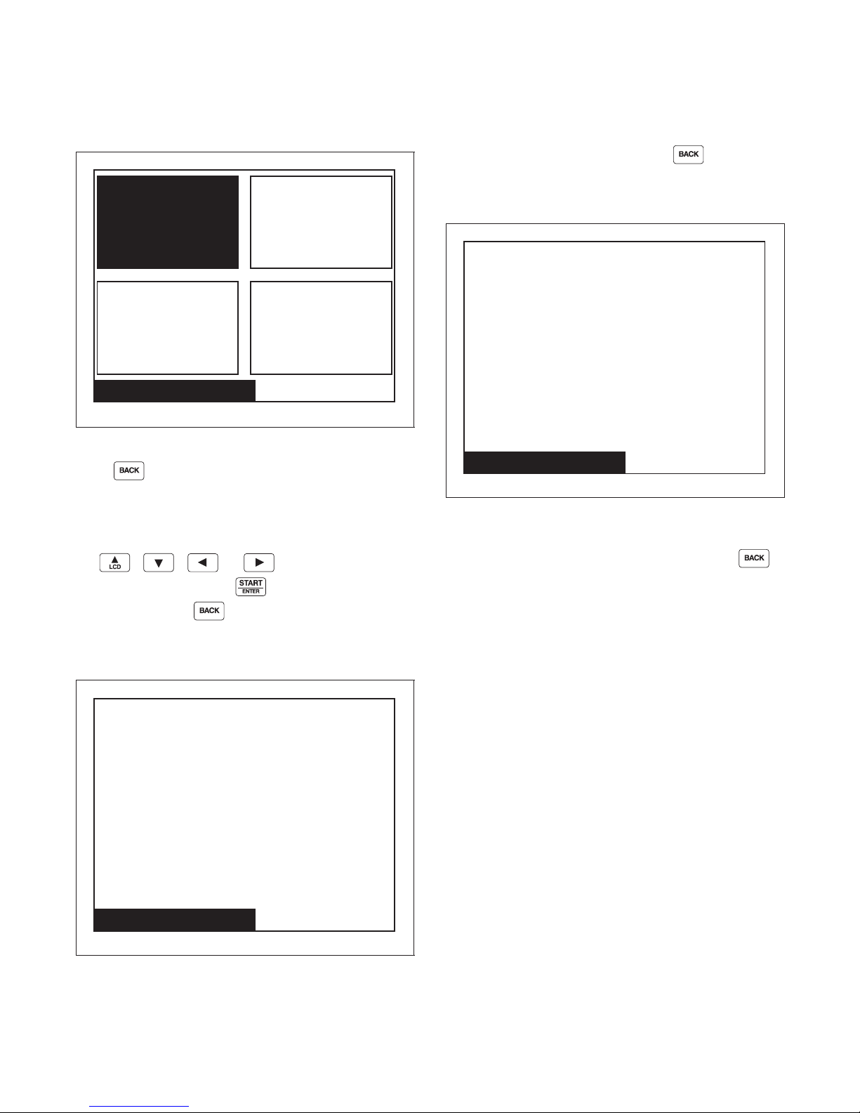
Maintenance
Monthly
Service Schedule Menu
Quarterly
WeeklyDaily
Service Schedule
Daily Maintenance Reminders:
1. Inspect all water inlets for leaks.
2. Inspect all chemical inlets, lines and connections
for leaks.
3. Clean inverter drive box filter.
4. Clean door gasket.
5. Clean top, front and side panels.
Service Schedule
Weekly Maintenance Reminders:
1. Check for leaks.
a. Start an unloaded cycle to fill machine.
b. Verify that the door and door gasket do not
leak.
c. Verify that the main drain valve is operating.
Service Schedule Menu
PHM707N
Figure 79
Press from Cycle Menu to enter Service
Schedule Menu. The Service Schedule Menu provides
a user with a time based service reminder list. The list
is broken up into “DAILY”, “WEEKLY”,
“MONTHLY”, and “QUARTERLY” Menus. Press
the or keypad to navigate
to a menu item. Press the keypad when menu is
The Daily Menu contains all daily service reminders
that need to be performed. Press the keypad to
return to the Service Menu.
Weekly Menu (Service)
PHM709N
Figure 81
The Weekly Menu contains all weekly service
reminders that need to be performed. Press the
keypad to return to the Service Menu.
selected. Press the keypad to return to Cycle
Menu.
Daily Menu (Service)
Figure 80
PHM708N
62
© Copyright, Alliance Laundry Systems LLC – DO NOT COPY or TRANSMIT
F8434101
Page 65
Maintenance
Service Schedule (1 of 2)
Monthly Maintenance Reminders:
1. Clean the inverter drive fins.
2. Inspect V belts for replacement or adjustment.
a. Check for uneven wear and frayed edges.
b. Verify belt tension.
c. Verify belt alignment.
3. Remove back panel and check hoses for leaks.
4. Check supply dispenser hoses and connections.
5. Clean inlet hose filter screens. Replace if worn
or damaged.
6. Inspect and tighten all bolts if required.
Service Schedule (2 of 2)
Monthly Maintenance Reminders:
7. Use compressed air to clean lint from motor.
8. Use compressed air to clean all electrical
components.
Service Schedule
Quarterly Maintenance Reminders:
1. Inspect and tighten door hinges and fasteners,
if necessary.
2. Tighten anchor bolts, if necessary.
Monthly Menu (Service)
Figure 82
PHM710N
Quarterly Menu (Service)
PHM711N
Figure 84
The Quarterly Menu contains all quarterly service
reminders that need to be performed. Press the
keypad to return to Service Menu.
Figure 83
The Monthly Menu contains all monthly service
reminders that need to be performed.
Press or to view Monthly Menu (2 of 2).
Press the keypad to return to Service Menu.
F8434101
© Copyright, Alliance Laundry Systems LLC – DO NOT COPY or TRANSMIT
PHM712N
63
Page 66

Cycle Charts
Cycle
No.
1
2
Cycle
Name
Tow els ,
White,
Bleach
Tow els ,
White
Cycle
Display
Name
Towels
White
Bleach
Towels
White
Segment
Number
& Name
#1 Wash Hot S1, ES1 18/3/18 Yes
#2 Wash Hot S2, ES2 18/3/18 Yes
#3 Rinse Warm 18/3/18 Yes
#4 Rinse Warm 18/3/18 Yes
#5 Rinse Warm 18/3/18 Yes Warm
#6 Rinse Warm S3, S4
#1 Wash Hot S1, ES1 18/3/18 Yes
#2 Rinse Warm 18/3/18 Yes
#3 Rinse Warm 18/3/18 Yes
#4 Rinse Warm 18/3/18 Yes Warm
#5 Rinse Warm S3, S4
Reuse
Fill
Step
Fill Supply ASupply BAgitate
Step
Low 45 Sec 8 Min
Low 45 Sec 8 Min
High 2 Min
High 2 Min
High 2 Min 2 Min
18/3/18 Yes Ultra
& ES3,
ES4
Low 45 Sec 4 Min 5 Min
Low 45 Sec 8 Min
High 2 Min
High 2 Min
High 2 Min 2 Min
18/3/18 Yes Ultra
& ES3,
ES4
Low 45 Sec 4 Min 5 Min
Table 6 (Continued)
Cool
Down
Drain Spray
Rinse
Extract
Extract EOS
Ye s
High
Ye s
High
64
© Copyright, Alliance Laundry Systems LLC – DO NOT COPY or TRANSMIT
F8434101
Page 67

Table 6 (Continued)
Cycle Charts
Cycle
No.
3
4
Cycle
Name
Towels,
Colors,
Oxygen
Towels,
Colors
Cycle
Display
Name
Towels
Colors
Oxygen
Towels
Colors
Segment
Number
& Name
Reuse
Fill
Step
Fill Supply ASupply BAgitate
Step
Cool
Down
Drain Spray
Rinse
Extract
#1 Wash Warm S1, ES1 18/3/18 Yes
Low 45 Sec 8 Min
#2 Wash Hot S2, ES2 18/3/18 Yes
Low 45 Sec 8 Min
#3 Rinse Cold 18/3/18 Yes
High 2 Min
#4 Rinse Cold 18/3/18 Yes
High 2 Min
#5 Rinse Cold 18/3/18 Yes Cold
High 2 Min 2 Min
#6 Rinse Warm S3, S4
18/3/18 Yes Ultra
& ES3,
ES4
Low 45 Sec 4 Min 5 Min
#1 Wash Warm S1, ES1 18/3/18 Yes
Low 45 Sec 8 Min
#2 Rinse Cold 18/3/18 Yes
High 2 Min
#3 Rinse Cold 18/3/18 Yes
High 2 Min
#4 Rinse Cold 18/3/18 Yes Cold
High 2 Min 2 Min
#5 Rinse Warm S3, S4
18/3/18 Yes Ultra
& ES3,
ES4
Low 45 Sec 4 Min 5 Min
Table 6 (Continued)
Extract EOS
Ye s
High
Ye s
High
F8434101
© Copyright, Alliance Laundry Systems LLC – DO NOT COPY or TRANSMIT
65
Page 68
Cycle Charts
Cycle
No.
Cycle
Name
Sheets,
White,
Bleach
5
Sheets,
White
6
Sheets,
Color,
Oxygen
7
Cycle
Display
Name
Sheets
White
Bleach
Sheets
White
Sheets
Color
Oxygen
Table 6 (Continued)
Segment
Number
& Name
Reuse
Fill
Step
Fill Supply ASupply BAgitate
Step
Cool
Down
Drain Spray
Rinse
Extract
#1 Wash Hot S1, ES1 18/3/18 Yes
Low 45 Sec 7 Min
#2 Wash Hot S2, ES2 18/3/18 Yes
Low 45 sec 7 Min
#3 Rinse Warm 18/3/18 Yes
High 2 Min
#4 Rinse Warm 18/3/18 Yes Warm
High 2 Min 2 Min
#5 Rinse Warm S3, S4
18/3/18 Yes Ultra
& ES3,
ES4
Low 45 Sec 5 Min 4 Min
#1 Wash Hot S1, ES1 18/3/18 Yes
Low 45 Sec 8 Min
#2 Rinse Warm 18/3/18 Yes
High 2 Min
#3 Rinse Warm 18/3/18 Yes Warm
High 2 Min 2 Min
#4 Rinse Warm S3, S4
18/3/18 Yes Ultra
& ES3,
ES4
Low 45 Sec 5 Min 4 Min
#1 Wash Warm S1, ES1 18/3/18 Yes
Low 45 Sec 7 Min
#2 Wash Warm S2, ES2 18/3/18 Yes
Low 45 sec 7 Min
#3 Rinse Cold 18/3/18 Yes
High 2 Min
#4 Rinse Cold 18/3/18 Yes Cold
High 2 Min 2 Min
#5 Rinse Warm S3, S4
18/3/18 Yes Ultra
& ES3,
ES4
Low 45 Sec 4 Min 4 Min
Table 6 (Continued)
Extract
High
High
High
EOS
Ye s
Ye s
Ye s
66
© Copyright, Alliance Laundry Systems LLC – DO NOT COPY or TRANSMIT
F8434101
Page 69

Cycle
No.
8
9
Cycle
Name
Sheets,
Color
Sheets,
White,
Bleach &
Ironer
Cycle
Display
Name
Sheets
Color
Sheets
White
B & I
Table 6 (Continued)
Segment
Number
& Name
Reuse
Fill
Step
Fill Supply ASupply BAgitate
Step
Cool
Down
Drain Spray
Rinse
Extract
#1 Wash Warm S1, ES1 18/3/18 Yes
Low 45 Sec 8 Min
#2 Rinse Cold 18/3/18 Yes
High 2 Min
#3 Rinse Cold 18/3/18 Yes Cold
High 2 Min 2 Min
#4 Rinse Warm S3, S4
18/3/18 Yes Ultra
& ES3,
ES4
Low 45 Sec 4 Min 4 min
#1 Wash Hot S1, ES1 18/3/18 Yes
Low 45 Sec 8 Min
#2 Wash Hot S2, ES2 18/3/18 Yes
Low 45 Sec 8 Min
#3 Rinse Warm 18/3/18 Yes
High 2 Min
#4 Rinse Warm 18/3/18 Yes
High 2 Min
#5 Rinse Warm 18/3/18 Yes Warm
High 2 Min 2 Min
#6 Rinse Warm S3, S4
18/3/18 Yes Ultra
& ES3,
ES4
Low 45 Sec 4 Min 5 min
Table 6 (Continued)
Cycle Charts
Extract EOS
Ye s
High
Ye s
High
F8434101
© Copyright, Alliance Laundry Systems LLC – DO NOT COPY or TRANSMIT
67
Page 70
Cycle Charts
Table 6 (Continued)
Cycle
No.
10
11
12
Cycle
Name
Sheets,
White,
Ironer
Sheets,
Color,
Oxygen
& Ironer
Sheets,
Color,
Ironer
Cycle
Display
Name
Sheets
White
Ironer
Sheets
Color
O & I
Sheets
Color
Ironer
Segment
Number
& Name
Reuse
Fill
Step
Fill Supply ASupply BAgitate
Step
Cool
Down
Drain Spray
Rinse
Extract
#1 Wash Hot S1, ES1 18/3/18 Yes
Low 45 Sec 8 Min
#2 Rinse Warm 18/3/18 Yes
High 2 Min
#3 Rinse Warm 18/3/18 Yes
High 2 Min
#4 Rinse Warm 18/3/18 Yes Warm
High 2 Min 2 Min
#5 Rinse Warm S3, S4
18/3/18 Yes Ultra
& ES3,
ES4
Low 45 Sec 4 Min 5 min
#1 Wash Warm S1, ES1 18/3/18 Yes
Low 45 Sec 8 Min
#2 Wash Warm S2, ES2 18/3/18 Yes
Low 45 Sec 8 Min
#3 Rinse Cold 18/3/18 Yes
High 2 Min
#4 Rinse Cold 18/3/18 Yes
High 2 Min
#5 Rinse Cold 18/3/18 Yes Cold
High 2 Min 2 Min
#6 Rinse Warm S3, S4
18/3/18 Yes Ultra
& ES3,
ES4
Low 45 Sec 4 Min 5 min
#1 Wash Warm S1, ES1 18/3/18 Yes
Low 45 Sec 8 Min
#2 Rinse Cold 18/3/18 Yes
High 2 Min
#3 Rinse Cold 18/3/18 Yes
High 2 Min
#4 Rinse Cold 18/3/18 Yes Cold
High 2 Min 2 Min
#5 Rinse Warm S3, S4
18/3/18 Yes Ultra
& ES3,
ES4
Low 45 Sec 4 Min 5 min
Table 6 (Continued)
Extract EOS
Ye s
High
Ye s
High
Ye s
High
68
© Copyright, Alliance Laundry Systems LLC – DO NOT COPY or TRANSMIT
F8434101
Page 71

Table 6 (Continued)
Cycle Charts
Cycle
No.
13
14
Cycle
Name
Blankets,
Spreads,
Warm
Blankets,
Spreads,
Cold
Cycle
Display
Name
Blanket
Spreads
Warm
Blanket
Spreads
Cold
Segment
Number
& Name
Reuse
Fill
Step
Fill Supply ASupply BAgitate
Step
Cool
Down
Drain Spray
Rinse
Extract
#1 Wash Warm S1, ES1 18/3/18 Yes
Low 45 Sec 8 Min
#2 Rinse Warm 18/3/18 Yes
High 2 Min
#3 Rinse Warm 18/3/18 Yes
High 2 Min
#4 Rinse Warm 18/3/18 Yes Warm
High 2 Min 2 Min
#5 Rinse Warm S3, S4
18/3/18 Yes Ultra
& ES3,
ES4
Low 45 Sec 4 Min 5 Min
#1 Wash Cold S1, ES1 18/3/18 Yes
Low 45 Sec 8 Min
#2 Rinse Cold 18/3/18 Yes
High 2 Min
#3 Rinse Cold 18/3/18 Yes
High 2 Min
#4 Rinse Cold 18/3/18 Yes Cold
High 2 Min 2 Min
#5 Rinse Warm S3, S4
18/3/18 Yes Ultra
& ES3,
ES4
High 45 Sec 4 Min 5 Min
Table 6 (Continued)
Extract EOS
Ye s
High
Ye s
High
F8434101
© Copyright, Alliance Laundry Systems LLC – DO NOT COPY or TRANSMIT
69
Page 72

Cycle Charts
Table 6 (Continued)
Cycle
No.
15
16
Cycle
Name
Sheets,
Health
Care
Towe ls,
Health
Care
Cycle
Display
Name
Sheets,
Health
Care
Towe ls
Health
Care
Segment
Number
& Name
#1 Pre
Wash
Reuse
Fill
Step
Fill Supply ASupply BAgitate
Step
Cool
Down
Drain Spray
Warm 18/3/18 Yes
High 2 Min
Rinse
Extract
#2 Wash Hot S1, ES1 18/3/18 Yes
Low 45 Sec 7 Min
#3 Wash Hot S2, ES2 18/3/18 Yes
Low 45 Sec 7 Min
#4 Rinse Warm 18/3/18 Yes
High 2 Min
#5 Rinse Warm 18/3/18 Yes Warm
High 2 Min 2 Min
#6 Rinse Warm S3, S4
18/3/18 Yes Ultra
& ES3,
ES4
Low 45 Sec 5 Min 4 Min
#1 Pre
Wash
Warm 18/3/18 Yes
High 2 Min
#2 Wash Hot S1, ES1 18/3/18 Yes
Low 45 Sec 8 Min
#3 Wash Hot S2, ES2 18/3/18 Yes
Low 45 Sec 8 Min
#4 Rinse Warm 18/3/18 Yes
High 2 Min
#5 Rinse Warm 18/3/18 Yes
High 2 Min
#6 Rinse Warm 18/3/18 Yes Warm
High 2 Min 2 Min
#7 Rinse Warm S3, S4
18/3/18 Yes Ultra
& ES3,
ES4
Low 45 Sec 4 Min 5 Min
Table 6 (Continued)
Extract EOS
Ye s
High
Ye s
High
70
© Copyright, Alliance Laundry Systems LLC – DO NOT COPY or TRANSMIT
F8434101
Page 73

Table 6 (Continued)
Cycle Charts
Cycle
No.
17
18
Cycle
Name
Patient,
Health
Care
Diapers,
Health
Care
Cycle
Display
Name
Patient
Health
Care
Diapers
Health
Care
Segment
Number
& Name
#1 Pre
Wash
Reuse
Fill
Step
Fill Supply ASupply BAgitate
Step
Warm 18/3/18 Yes
High 2 Min
Cool
Down
Drain Spray
Rinse
Extract
#2 Wash Warm S1, ES1 18/3/18 Yes
Low 45 Sec 7 Min
#3 Rinse Warm 18/3/18 Yes
High 2 Min
#4 Rinse Warm 18/3/18 Yes Warm
High 2 Min 2 Min
#5 Rinse Warm S3, S4
18/3/18 Yes Medium Yes
& ES3,
ES4
Low 45 Sec 4 Min 4 Min
#1 Pre
Wash
#2 Pre
Wash
#3 Pre
Wash
Warm 18/3/18 Yes
High 2 Min
Warm 18/3/18 Yes
High 2 Min
Warm 18/3/18 Yes
High 2 Min
#4 Wash Hot S1, ES1 18/3/18 Yes
Low 45 Sec 10 Min
#5 Wash Hot S2, ES2 18/3/18 Yes
Low 45 Sec 10 Min
#6 Rinse Warm 18/3/18 Yes
High 2 Min
#7 Rinse Warm 18/3/18 Yes
High 2 Min
#8 Rinse Warm 18/3/18 Yes Warm
High 2 Min 2 Min
#9 Rinse Warm S3, S4
18/3/18 Yes Ultra
& ES3,
ES4
Low 45 Sec 4 Min 5 Min
Table 6 (Continued)
Extract EOS
Ye s
High
F8434101
© Copyright, Alliance Laundry Systems LLC – DO NOT COPY or TRANSMIT
71
Page 74

Cycle Charts
Table 6 (Continued)
Cycle
No.
19
20
Cycle
Name
Blankets/
Spreads
Health
Care
Napery
White
Bleach
Cycle
Display
Name
Blanket
Health
Care
Napery
White
Bleach
Segment
Number
& Name
#1 Pre
Wash
Reuse
Fill
Step
Fill Supply ASupply BAgitate
Step
Cool
Down
Drain Spray
Warm 18/3/18 Yes
High 2 Min
Rinse
Extract
#2 Wash Warm S1, ES1 18/3/18 Yes
Low 45 Min 7 Min
#3 Rinse Warm 18/3/18 Yes
High 2 Min
#4 Rinse Warm 18/3/18 Yes
High 2 Min
#5 Rinse Warm 18/3/18 Yes Warm
High 2 Min 2 Min
#6 Rinse Warm S3, S4
18/3/18 Yes Medium Yes
& ES3,
ES4
Low 45 Sec 4 Min 5 Min
#1 Pre
Wash
Warm 18/3/18 Yes
High 2 Min
#2 Wash Hot S1, ES1 18/3/18 Yes
Low 45 Sec 7 Min
#3 Wash Hot S2, ES2 18/3/18 Yes
Low 45 Sec 7 Min
#4 Rinse Warm 18/3/18 Yes
High 2 Min
#5 Rinse Warm 18/3/18 Yes
High 2 Min
#6 Rinse Warm 18/3/18 Yes Warm
High 2 Min 2 Min
#7 Rinse Warm S3, S4
18/3/18 Yes Medium Yes
& ES3,
ES4
Low 45 Sec 4 Min 3 Min
Table 6 (Continued)
Extract EOS
72
© Copyright, Alliance Laundry Systems LLC – DO NOT COPY or TRANSMIT
F8434101
Page 75

Table 6 (Continued)
Cycle Charts
Cycle
No.
21
22
Cycle
Name
Napery
White
Bleach &
Ironer
Napery
Color
Cycle
Display
Name
Napery
White
B & I
Napery
Color
Segment
Number
& Name
#1 Pre
Wash
Reuse
Fill
Step
Fill Supply ASupply BAgitate
Step
Cool
Down
Drain Spray
Warm S1, ES1 18/3/18 Yes
Low 45 Sec 7 Min
Rinse
Extract
Extract EOS
#2 Wash Hot S2, ES2 18/3/18 Yes
Low 45 Sec 7 Min
#3 Rinse Warm 18/3/18 Yes
High 2 Min
#4 Rinse Warm 18/3/18 Yes
High 2 Min
#5 Rinse Warm 18/3/18 Yes Warm
High 2 Min 2 Min
#6 Rinse Warm S5, ES5 18/3/18 Yes Ultra
High
Low 45 Sec 4 Min 5 Min
#1 Pre
Wash
Warm 18/3/18 Yes
High 2 Min
#2 Wash Hot S1, ES1 18/3/18 Yes
Low 45 Sec 10 min
#3 Rinse Warm 18/3/18 Yes
High 2 Min
#4 Rinse Cold 18/3/18 Yes
High 2 Min
#5 Rinse Cold 18/3/18 Yes Cold
High 2 Min 2 Min
#6 Rinse Warm S3, S4
18/3/18 Yes Medium Yes
& ES3,
ES4
Low 45 Sec 4 Min 3 Min
Table 6 (Continued)
Ye s
F8434101
© Copyright, Alliance Laundry Systems LLC – DO NOT COPY or TRANSMIT
73
Page 76

Cycle Charts
Table 6 (Continued)
Cycle
No.
23
24
Cycle
Name
Napery
Color
Oxygen
Napery
Color
Ironer
Cycle
Display
Name
Napery
Color
Oxygen
Napery
Color
Ironer
Segment
Number
& Name
#1 Pre
Wash
Reuse
Fill
Step
Fill Supply ASupply BAgitate
Step
Cool
Down
Drain Spray
Warm 18/3/18 Yes
High 2 Min
Extract EOS
Rinse
Extract
#2 Wash Hot S1, ES1 18/3/18 Yes
Low 45 Sec 7 Min
#3 Wash Hot S2, ES2 18/3/18 Yes
Low 45 Sec 7 Min
#4 Rinse Warm 18/3/18 Yes
High 2 Min
#5 Rinse Cold 18/3/18 Yes
High 2 Min
#6 Rinse Cold 18/3/18 Yes Cold
High 2 Min 2 Min
#7 Rinse Warm S3, S4
18/3/18 Yes Medium Yes
& ES3,
ES4
Low 45 Sec 4 Min 3 Min
#1 Pre
Warm 18/3/18 Yes
Wash
High 2 Min
#2 Wash Hot S1, ES1 18/3/18 Yes
Low 45 Sec 10 Min
#3 Rinse Warm 18/3/18 Yes
High 2 Min
#4 Rinse Warm 18/3/18 Yes
High 2 Min
#5 Rinse Warm 18/3/18 Yes Warm
High 2 Min 2 Min
#6 Rinse Warm S5, ES5 18/3/18 Yes Ultra
High
Low 45 Sec 4 Min 5 Min
Table 6 (Continued)
Ye s
74
© Copyright, Alliance Laundry Systems LLC – DO NOT COPY or TRANSMIT
F8434101
Page 77

Table 6 (Continued)
Cycle Charts
Cycle
No.
25
26
27
Cycle
Name
Napery
Color
Oxygen
& Ironer
Shirts/
Uniforms
White
Bleach
Shirts
White
Bleach
Starch
Cycle
Display
Name
Napery
C ol o r
O & I
Shrt/
Unifrm
Wht
Blch
Shirts
Bleach
Starch
Segment
Number
& Name
#1 Pre
Wash
Reuse
Fill
Step
Fill Supply ASupply BAgitate
Step
Cool
Down
Drain Spray
Warm S1, ES1 18/3/18 Yes
Low 45 Sec 7 Min
Rinse
Extract
Extract EOS
#2 Wash Hot S2, ES2 18/3/18 Yes
Low 45 Sec 7 Min
#3 Rinse Warm 18/3/18 Yes
High 2 Min
#4 Rinse Warm 18/3/18 Yes
High 2 Min
#5 Rinse Warm 18/3/18 Yes Warm
High 2 Min 2 Min
#6 Rinse Warm S5, ES5 18/3/18 Yes Ultra
High
Low 45 Sec 4 Min 5 Min
#1 Wash Hot S1, ES1 18/3/18 Yes
Low 45 Sec 7 Min
#2 Wash Hot S2, ES2 18/3/18 Yes
Low 45 Sec 7 Min
#3 Rinse Warm 18/3/18 Yes
High 2 Min
#4 Rinse Warm 18/3/18 Yes Warm
High 2 Min 2 Min
#5 Rinse Warm S3, S4
& ES3,
18/3/18 Yes Ultra
High
ES4
Low 45 Sec 4 Min 5 Min
#1 Wash Hot S1, ES1 18/3/18 Yes
Low 45 Sec 7 Min
#2 Wash Hot S2, ES2 18/3/18 Yes
Low 45 Sec 7 Min
#3 Rinse Warm 18/3/18 Yes
High 2 Min
#4 Rinse Warm 18/3/18 Yes Warm
High 2 Min 2 Min
#5 Rinse Warm S5, ES5 18/3/18 Yes Ultra
High
Low 45 Sec 4 Min 5 Min
Table 6 (Continued)
Ye s
Ye s
Ye s
F8434101
© Copyright, Alliance Laundry Systems LLC – DO NOT COPY or TRANSMIT
75
Page 78

Cycle Charts
Table 6 (Continued)
Cycle
No.
28
29
30
31
Cycle
Name
Shirts/
Uniforms
Color
Shirts
Color
Starch
Starch &
Spin Only
ECO
Towe ls
Cycle
Display
Name
Shirt/
Uniform
Color
Shirts
Color
Starch
Starch
Spin
Only
ECO
Towe ls
Segment
Number
& Name
Reuse
Fill
Step
Fill Supply ASupply BAgitate
Step
Cool
Down
Drain Spray
Rinse
Extract
Extract EOS
#1 Wash Warm S1, ES1 18/3/18 Yes
Low 45 Sec 10 Min
#2 Rinse Warm 18/3/18 Yes
High 2 Min
#3 Rinse Warm 18/3/18 Yes Warm
High 2 Min 2 Min
#4 Rinse Warm S3, S4
& ES3,
18/3/18 Yes Ultra
High
ES4
Low 45 Sec 4 Min 5 Min
#1 Wash Warm S1, ES1 18/3/18 Yes
Low 45 Sec 10
#2 Rinse Warm 18/3/18 Yes
High 2 Min
#3 Rinse Warm 18/3/18 Yes Warm
High 2 Min 2 Min
#4 Rinse Warm S5, ES5 18/3/18 Yes Ultra
High
Low 45 Sec 4 Min 5 Min
#1 Rinse Warm S3, S5
& ES3,
18/3/18 Yes Ultra
High
ES5
Low 45 Sec 7 Min 5 Min
#1 Wash Hot S1, S2,
18/3/18 Yes Warm
ES1,
ES2
Low 45 Sec 8 Min 2 Min
30 Sec
#2 Rinse Warm S3, S4,
ES3,
18/3/18 Yes Ultra
High
ES4
Low 45 Sec 4 Min 5 Min
Table 6 (Continued)
Ye s
Ye s
Ye s
Ye s
76
© Copyright, Alliance Laundry Systems LLC – DO NOT COPY or TRANSMIT
F8434101
Page 79

Table 6 (Continued)
Cycle Charts
Cycle
No.
32
33
Cycle
Name
ECO
Sheets
Rags &
Mops
Cycle
Display
Name
ECO
Sheets
Rags &
Mops
Segment
Number
& Name
Reuse
Fill
Step
Fill Supply ASupply BAgitate
#1 Wash Hot S1, S2,
ES1,
Cool
Drain Spray
Step
Down
Rinse
Extract
18/3/18 Yes Warm Very
Extract EOS
Low
ES2
Low 45 Sec 8 Min 10 Sec 20 Sec
#2 Rinse Warm 18/3/18 Yes Warm Very
Low
High 2 Min 20 Sec 10 Sec
#3 Rinse Warm S3, S4
& ES3,
18/3/18 Yes Ultra
High
ES4
Low 45 Sec 4 Min 4 Min
#1 Pre
Wash
#2 Pre
Wash
#3 Pre
Wash
#4 Pre
Wash
Warm 18/3/18 Yes
High 2 Min
Warm 18/3/18 Yes
High 2 Min
Warm 18/3/18 Yes
High 2 Min
Warm 18/3/18 Yes
High 2 Min
#5 Wash Hot S1, ES1 18/3/18 Yes
Low 45 Sec 8 Min
#6 Wash Hot S2, ES2 18/3/18 Yes
Low 45 Sec 8 Min
#7 Rinse Warm 18/3/18 Yes
High 2 Min
#8 Rinse Warm 18/3/18 Yes
High 2 Min
#9 Rinse Warm S3, S4
& ES3,
18/3/18 Yes Ultra
High
ES4
Low 2 Min 5 Min
Table 6 (Continued)
Ye s
Ye s
F8434101
© Copyright, Alliance Laundry Systems LLC – DO NOT COPY or TRANSMIT
77
Page 80

Cycle Charts
Table 6 (Continued)
Cycle
No.
34
35
Cycle
Name
Stain
Reclaim
Heavy
Soil
Bleach
Cycle
Display
Name
Stain
Reclaim
Heavy
Soil
Bleach
Segment
Number
& Name
#1 Wash Hot S1, S2
Reuse
Fill
Step
Fill Supply ASupply BAgitate
Step
18/3/18 Yes
Cool
Down
Drain Spray
Rinse
Extract
Extract EOS
& ES1,
ES2
Low 45 Sec 30 Min
#2 Rinse Warm 18/3/18 Yes
High 2 Min
#3 Rinse Warm 18/3/18 Yes
High 2 Min
#4 Rinse Warm 18/3/18 Yes Warm
High 2 Min 2 Min
#5 Rinse Warm 18/3/18 Yes Ultra
High
High 5 Min 5 Min
#1 Pre
Wash
#2 Pre
Wash
Warm 18/3/18 Yes
High 2 Min
Warm 18/3/18 Yes
High 2 Min
#3 Wash Hot S1, ES1 18/3/18 Yes
Low 45 Sec 8 Min
#4 Wash Hot S1, ES1 18/3/18 Yes
Low 45 Sec 8 Min
#5 Wash Hot S2, ES2 18/3/18 Yes
Low 45 Sec 8 Min
#6 Rinse Warm 18/3/18 Yes
High 2 Min
#7 Rinse Warm 18/3/18 Yes
High 2 Min
#8 Rinse Warm 18/3/18 Yes Warm
High 2 Min 2 Min
#9 Rinse Warm S3, S4
& ES3,
18/3/18 Yes Ultra
High
ES4
Low 45 Sec 4 Min 5 Min
Table 6 (Continued)
Ye s
Ye s
78
© Copyright, Alliance Laundry Systems LLC – DO NOT COPY or TRANSMIT
F8434101
Page 81

Table 6 (Continued)
Cycle Charts
Cycle
No.
36
37
38
39
Cycle
Name
Overnight
Soak
Cycle
Display
Name
Over
Night
Soak
Segment
Number
& Name
#1 Pre
Wash
Reuse
Fill
Step
Fill Supply ASupply BAgitate
Step
Hot 18/3/18 Yes
High 2 Min
#2 Wash Hot S1, ES1 No
Cool
Down
Drain Spray
Ye s
Rotate
High 45 Sec 8 Hours
#3 Rinse Warm 18/3/18 Yes
High 2 Min
#4 Rinse Warm 18/3/18 Yes
High 2 Min
#5 Rinse Warm S3, S4
18/3/18 Yes Ultra
& ES3,
ES4
High 45 Sec 4 Min 5 Min
Rinse &
Spin
Rinse
Spin
Only
#1 Rinse Warm 18/3/18 Yes Ultra
Low 2 Min 4 Min
Delicate Delicate #1 Wash Cold S1, ES1 3/27/3 Yes
Med 45 Sec 6 Min
#2 Rinse Cold 3/27/3 Yes
High 2 Min
#3 Rinse Cold 3/27/3 Yes
High 2 Min
#4 Rinse Warm S3, S4
3/27/3 Yes Very
& ES3,
ES4
Low 45 Sec 5 Min 2 Min
General
Short
General
Short
#1 Wash Hot S1, ES1 18/3/18 Yes
Low 12 Min
#2 Rinse Warm 18/3/18 Yes Medium
High 3 Min 1 Min
#3 Rinse Warm 18/3/18 Yes Warm Ultra
High 3 Min 2 Min 5 Min
Table 6 (Continued)
Extract EOS
Rinse
Extract
Ye s
High
Ye s
High
Ye s
Low
Ye s
High
F8434101
© Copyright, Alliance Laundry Systems LLC – DO NOT COPY or TRANSMIT
79
Page 82

Cycle Charts
Table 6 (Continued)
Cycle
No.
40
41
Cycle
Name
General
Long
Supply
Set Up
Cycle
Display
Name
General
Long
Supply
Set Up
Segment
Number
& Name
#1 Pre
Wash
Reuse
Fill
Step
Fill Supply ASupply BAgitate
Step
Cool
Down
Drain Spray
Warm 18/3/18 Yes
High 2 Min
Extract EOS
Rinse
Extract
#2 Wash Hot S1, ES1 18/3/18 Yes
Low 45 Sec 15 Min
#3 Rinse Warm 18/3/18 Yes Medium
High 3 Min 1 Min
#4 Rinse Warm 18/3/18 Yes Warm Ultra
Ye s
High
High 3 Min 2 Min 5 Min
#1 Rinse Warm S1, S2
&
ES1,
ES2
S3, S4,
S 5 &
ES3,
ES4,
18/3/18 Yes
ES5
Low 45 Sec 45 Sec 2 Min
#2 Rinse Warm 18/3/18 Yes Yes
Low 1 Min
Tab le 6
80
© Copyright, Alliance Laundry Systems LLC – DO NOT COPY or TRANSMIT
F8434101
 Loading...