

Page 1
Washer-Extractors
Cabinet Freestanding
Instructions for Operating and Programming
the WE-6 Microcomputer
Models SF35PV, SF50PV, SF85PV,
UF35PV, UF50PV and UF85PV
NOTA: El manual en
español aparece después
del manual en inglés.
Operation/Programming
Keep These Instructions for Future Reference.
(If this machine changes ownership, this manual must accompany machine.)
www.comlaundry.com
R077R
Part No. F232059R7
January 2002
Page 2

Page 3

Table of
Contents
Safety.................................................................................................... 3
Key to Symbols..................................................................................... 4
Operator Safety..................................................................................... 5
Safe Operating Environment ................................................................ 6
Environmental Conditions............................................................... 6
Machine Location ............................................................................ 7
Input and Output Services................................................................ 7
AC Inverter Drive ............................................................................ 8
Misuse................................................................................................... 8
Operation............................................................................................. 9
Customer Service............................................................................. 9
Machine Familiarization Guides...................................................... 10
Theory of Operation ............................................................................. 12
Emergency Stop Button................................................................... 12
Wet Clean Features.......................................................................... 12
Wet Clean Capabilities......................................................................... 13
Wet Clean Functions........................................................................ 13
WE-6 Microcomputer ...................................................................... 15
LED Display .................................................................................... 15
Operational Keypad ......................................................................... 18
Start-Up................................................................................................. 20
Opening Door ....................................................................................... 20
Loading................................................................................................. 20
Supply Dispenser.................................................................................. 21
Cycle Selection..................................................................................... 21
Cycle Execution.................................................................................... 21
Test Cycle............................................................................................. 22
Wet Clean Testing............................................................................ 22
Stop Routine ......................................................................................... 23
Balance Detection................................................................................. 24
Balance Sensor Detection ................................................................ 24
Inverter Drive Balance Detection .................................................... 24
Temperature Display ............................................................................ 25
Calibrating the WE-6 Temperature Circuit...................................... 25
Error Recovery Routine........................................................................ 27
Thermal Overload Indicator ................................................................. 28
Resetting Thermal Overload Switch................................................ 28
Manual Mode Control Feature.............................................................. 29
Programming ...................................................................................... 31
Programming Keypad........................................................................... 31
Programming Tutorial .......................................................................... 33
Programming Hints............................................................................... 36
System Programming............................................................................ 37
© Copyright 2002, Alliance Laundry Systems LLC
All rights reserved. No part of the contents of this book may be reproduced or transmitted in any form or by any
means without the expressed written consent of the publisher.
F232059
© Copyright, Alliance Laundry Systems LLC – DO NOT COPY or TRANSMIT
1
Page 4

Cycle Programming.............................................................................. 39
Displaying a Cycle in Memory........................................................ 39
Displaying Individual Cycle Usage ................................................. 39
Editing a Cycle................................................................................. 40
Erasing a Cycle in Memory ............................................................. 41
Programming a Wet Clean Cycle .................................................... 41
Step Programming ................................................................................ 42
Programming a Fill Temperature..................................................... 42
Programming a Supply Step – Models with 5 Supplies .................. 43
Programming a Supply Step – Models with 8 Supplies .................. 44
Programming Heat........................................................................... 47
Programming a Wash Step............................................................... 47
Programming a Wash 5 Thermal Cool-Down ................................. 48
Programming No Reversing ............................................................ 49
Programming a Soak Step................................................................ 49
Programming a Drain Step............................................................... 50
Programming a Spin Step ................................................................ 50
Programming an Auxiliary Step ...................................................... 50
Simulator Operation and Program Transfer ......................................... 52
Simulator Operation......................................................................... 52
Transferring All Cycles from Computer to Simulator..................... 54
Transferring One Cycle from Computer to Simulator..................... 54
Transferring All Cycles from Simulator to Computer..................... 55
Transferring One Cycle from Simulator to Computer..................... 55
Preprogrammed Cycles......................................................................... 56
Cycle Categories.............................................................................. 56
Standard Supply Legend.................................................................. 57
Standard Cycle Charts...................................................................... 58
Sample Cycle for Wet Clean ................................................................ 78
2
© Copyright, Alliance Laundry Systems LLC – DO NOT COPY or TRANSMIT
F232059
Page 5
Safety
Be careful around the open door,
particularly when loading from a level
below the door. Impact with door edges
can cause personal injury.
SW025
CAUTION
Dangerous voltages are present in the
electrical control box(es) and at the motor
terminals. Only qualified personnel
familiar with electrical test procedures,
test equipment, and safety precautions
should attempt adjustments and
troubleshooting. Disconnect power from
the machine before removing the control
box cover, and before attempting any
service procedures.
SW005
WARNING
Death or serious injury can result if
children become trapped in the machine.
Do not allow children to play on or around
this machine. Do not leave children
unattended while the machine door is
open.
SW001
DANGER
Anyone operating or servicing this machine must
follow the safety rules in this manual. Particular
attention must be paid to the CAUTION, WARNING,
and DANGER blocks which appear throughout the
manual.
The following warnings are general examples that
apply to this machine. Warnings specific to a particular
operation will appear in the manual with the
discussion of that operation.
WARNING
This machine must be installed, adjusted,
and serviced by qualified electrical
maintenance personnel familiar with the
construction and operation of this type of
machinery. They must also be familiar
with the potential hazards involved.
Failure to observe this warning may result
in personal injury and/or equipment
damage, and may void the warranty.
SW004
CAUTION
Ensure that the machine is installed on a
level floor of sufficient strength and that
the recommended clearances for
inspection and maintenance are provided.
Never allow the inspection and
maintenance space to be blocked.
SW020
F232059
© Copyright, Alliance Laundry Systems LLC – DO NOT COPY or TRANSMIT
WARNING
Never touch internal or external steam
pipes, connections, or components.
These surfaces can be extremely hot and
will cause severe burns. The steam must
be turned off and the pipe, connections,
and components allowed to cool before
the pipe can be touched.
SW014
3
Page 6

Safety
Key to Symbols
The lightning flash and arrowhead within the triangle
is a warning sign indicating the presence of dangerous
voltage.
This warning symbol indicates the presence of
possibly dangerous chemicals. Proper precautions
should be taken when handling corrosive or caustic
materials.
The exclamation point within the triangle is a warning
sign indicating important instructions concerning the
machine and possibly dangerous conditions.
This warning symbol indicates the presence of
potentially dangerous drive mechanisms within the
machine. Guards should always be in place when the
machine is in operation.
This warning symbol indicates the presence of hot
surfaces that could cause serious burns. Stainless steel
and steam lines can become extremely hot and should
not be touched.
This warning symbol indicates the presence of
possibly dangerous pinch-points. Moving mechanical
parts can crush and/or sever body parts.
To provide personal safety and keep the machine in
proper working order, follow all maintenance and
safety procedures presented in this manual. If
questions regarding safety arise, contact the factory
immediately.
Use factory-authorized spare parts to avoid safety
hazards.
4
© Copyright, Alliance Laundry Systems LLC – DO NOT COPY or TRANSMIT
F232059
Page 7

Safety
NEVER insert hands or objects into
basket until it has completely stopped.
Doing so could result in serious injury.
SW012
WARNING
Operator Safety
To ensure the safety of machine operators, the
following maintenance checks must be performed
daily:
1. Prior to operating the machine, verify that all
warning signs are present and legible. Missing or
illegible signs must be replaced immediately.
Make certain that spares are available.
2. Check door interlock before starting operation of
the machine:
a. Attempt to start the machine with the door
open. The machine should not start with the
door open. Although the WE-6 display shows
cycle steps, the machine should not operate.
b. Close the door without locking it and attempt
to start the machine. The machine should not
start with the door unlocked.
3. Do not attempt to operate the machine if any of
the following conditions are present:
a. The door does not remain securely locked
during the entire cycle.
b. Excessively high water level is evident.
c. Machine is not connected to a properly
grounded circuit.
Do not bypass any safety devices in the machine.
WARNING
Never operate the machine with a
bypassed or disconnected out-of-balance
switch. Operating the machine with
severe out-of-balance loads could result
in personal injury and serious equipment
damage.
SW033
c. Close and lock the door and start a cycle.
Attempt to open the door while the cycle is in
progress. The door should not open.
If the door lock and interlock are not functioning
properly, call a service technician.
F232059
© Copyright, Alliance Laundry Systems LLC – DO NOT COPY or TRANSMIT
5
Page 8

Safety
Safe Operating Environment
Safe operation requires an appropriate operating
environment for both the operator and the machine. If
questions regarding safety arise, contact the factory
immediately.
Environmental Conditions
● Ambient Temperature. Water in the machine will
freeze at temperatures of 32°F (0°C) or below.
Temperatures above 120°F (50°C) will result in
more frequent motor overheating and, in some
cases, malfunction or premature damage to solid
state devices that are used in some models.
Special cooling devices may be necessary.
Water pressure switches are affected by increases
and decreases in temperature. Every 25°F (10°C)
change in temperature will have a 1% effect on
the water level.
● Humidity. Relative humidity above 90% may
cause the machine’s electronics or motors to
malfunction or may trip the ground fault
interrupter. Corrosion problems may occur on
some metal components in the machine.
If the relative humidity is below 30%, belts and
rubber hoses may eventually develop dry rot.
This condition can result in hose leaks, which
may cause safety hazards external to the machine
in conjunction with adjacent electrical
equipment.
● Radio Frequency Emissions. A filter is available
for machines in installations where floor space is
shared with equipment sensitive to radio
frequency emissions.
● Elevation. If the machine is to be operated at
elevations of over 3280 ft. (1000 m) above sea
level, pay special attention to water levels and
electronic settings (particularly temperature) or
desired results may not be achieved.
● Chemicals. Keep stainless steel surfaces free of
chemical residues.
DANGER
Do not place volatile or flammable fluids
in any machine. Do not clean the machine
with volatile or flammable fluids such as
acetone, lacquer thinners, enamel
reducers, carbon tetrachloride, gasoline,
benzene, naptha, etc. Doing so could
result in serious personal injury and/or
damage to the machine.
SW002
● Water Damage. Do not spray the machine with
water. Short circuiting and serious damage may
result. Repair immediately all seepage due to
worn or damaged gaskets, etc.
● Ventilation. The need for make-up air openings
for laundry room accessories such as dryers,
ironers, and water heaters must be evaluated
periodically. Louvers, screens, or other
separating devices may reduce the available air
opening significantly.
6
© Copyright, Alliance Laundry Systems LLC – DO NOT COPY or TRANSMIT
F232059
Page 9
Safety
Replace all panels that are removed to
perform service and maintenance
procedures. Do not operate the machine
with missing guards or with broken or
missing parts. Do not bypass any safety
devices.
SW019
CAUTION
Machine Location
● Foundation. The concrete floor must be of
sufficient strength and thickness to handle the
floor loads generated by the high extract speeds
of the machine.
● Service/Maintenance Space. Provide sufficient
space to allow comfortable performance of
service procedures and routine preventive
maintenance.
This is especially important in connection with
machines equipped with an AC inverter drive.
Consult installation instructions for specific details.
Input and Output Services
● Water Pressure. Best performance will be
realized if water is provided at a pressure of
30-85 psi (2.0-5.7 bar). Although the machine
will function properly at lower pressure,
increased fill times will occur. Water pressure
higher than 100 psi (6.7 bar) may result in
damage to machine plumbing. Component
failure(s) and personal injury could result.
● Steam Heat (Optional) Pressure. Best
performance will be realized if steam is provided
at a pressure of 30-80 psi (2.0-5.4 bar). Steam
pressure higher than 125 psi (8.5 bar) may result
in damage to steam components and may cause
personal injury.
● Compressed Air. For machines requiring
compressed air service, best performance will
be realized if air is provided at a pressure of
80-100 psi (5.4-6.7 bar).
● Drainage System. Provide drain lines or troughs
large enough to accommodate the total number of
gallons that could be dumped if all machines on
the site drained at the same time from the highest
attainable level. If troughs are used, they should
be covered to support light foot traffic.
● Pow er. For personal safety and for proper
operation, the machine must be grounded in
accordance with state and local codes. The
ground connection must be to a proven earth
ground, not to conduit or water pipes. Do not use
fuses in place of the circuit breaker. An easyaccess cutoff switch should also be provided.
WARNING
Ensure that a ground wire from a proven
earth ground is connected to the ground
lug near the input power block on this
machine. Without proper grounding,
personal injury from electric shock could
occur and machine malfunctions may be
evident.
SW008
Always disconnect power and water supplies before a
service technician performs any service procedure.
Where applicable, steam and/or compressed air
supplies should also be disconnected before service is
performed.
For machines equipped with optional steam heat,
install piping in accordance with approved
commercial steam practices. Failure to install the
supplied steam filter may void the warranty.
F232059
© Copyright, Alliance Laundry Systems LLC – DO NOT COPY or TRANSMIT
7
Page 10

Safety
AC Inverter Drive
Machines equipped with the AC inverter drive require
special attention with regard to the operating
environment.
● An especially dusty or linty environment will
require more frequent cleaning of the AC inverter
drive cooling fan filter(s) and of the AC inverter
drive itself.
● Power line fluctuations from sources such as
uninterruptible power supplies (UPS) can
adversely affect machines equipped with the AC
inverter drive. Proper suppression devices should
be utilized on the incoming power to the machine
to avoid problems.
● A clean power supply free from voltage spikes
and surges is absolutely essential for machines
equipped with the AC inverter drive. Nonlinear
inconsistencies (peaks and valleys) in the power
supply can cause the AC inverter drive to
generate nuisance errors.
● If voltage is above 240 Volt for 200 Volt
installation, ask the power company to correct.
As an alternative, a step-down transformer kit is
available from the distributor. If voltage is above
480 Volt for 400 Volt installation, a buckboost
transformer is required.
Misuse
Never use this machine for any purpose other than
washing fabric.
● Never wash petroleum-soaked rags in the
machine. This could result in an explosion.
● Never wash machine parts or automotive parts in
the machine. This could result in serious damage
to the basket.
● Never allow children to play on or around this
machine. Death or serious injury can result if
children become trapped in the machine. Do not
leave children unattended while the machine door
is open. These cautions apply to animals as well.
● Sufficient space to perform service procedures
and routine preventive maintenance is especially
important for machines equipped with the AC
inverter drive.
8
© Copyright, Alliance Laundry Systems LLC – DO NOT COPY or TRANSMIT
F232059
Page 11

Operation
This manual is designed as a guide for operating and
programming the 35, 50 and 85 pound capacity
freestanding washer-extractors equipped with the
WE-6 microcomputer and an AC inverter drive. These
washer-extractors feature programmable custom
cycles and high extract force. Wet cleaning capability
and water reuse capability offer the operator versatility
and economy.
The manuals, installation instructions, and wiring
diagrams which accompany the washer-extractor have
been included at no charge. Additional copies are
available at a nominal charge.
NOTE: Read this manual thoroughly before
attempting to operate the washer-extractor or
program the microcomputer.
NOTE: Do not use this manual in conjunction with
earlier model microcomputer-controlled
freestanding washer-extractors. Do not use
technical literature intended for earlier models
when operating this machine.
NOTE: All information, illustrations, and
specifications contained in this manual are based
on the latest product information available at the
time of printing. We reserve the right to make
changes at any time without notice.
Customer Service
If literature or replacement parts are required, contact
the source from whom the washer-extractor was
purchased or contact Alliance Laundry Systems LLC
at (920) 748-3950 for the name and address of the
nearest authorized parts distributor.
For technical service, call any of the following
numbers:
(920) 748-3121
Ripon, Wisconsin
(850) 718-1025
(850) 718-1026
Marianna, Florida
A record of each washer-extractor is on file with the
manufacturer. Always provide the washer-extractor’s
serial number and model number when ordering parts
or when seeking technical assistance.
F232059
© Copyright, Alliance Laundry Systems LLC – DO NOT COPY or TRANSMIT
9
Page 12
Operation
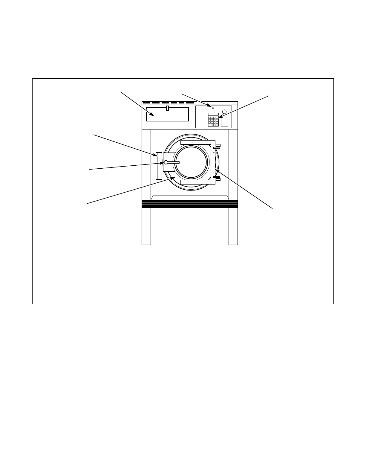
Machine Familiarization Guides
The machine familiarization guides in Figure 1 and
Figure 2 identify major operational features of each
washer-extractor.
7
6
5
4
1 Front Control Module Lock 5 Door Handle
2 Computer Keypad 6 Door Lock Box
3 Door Hinge 7 Supply Dispenser
4 Door
1
CFS227R
2
3
FS227R
10
Figure 1
© Copyright, Alliance Laundry Systems LLC – DO NOT COPY or TRANSMIT
F232059
Page 13
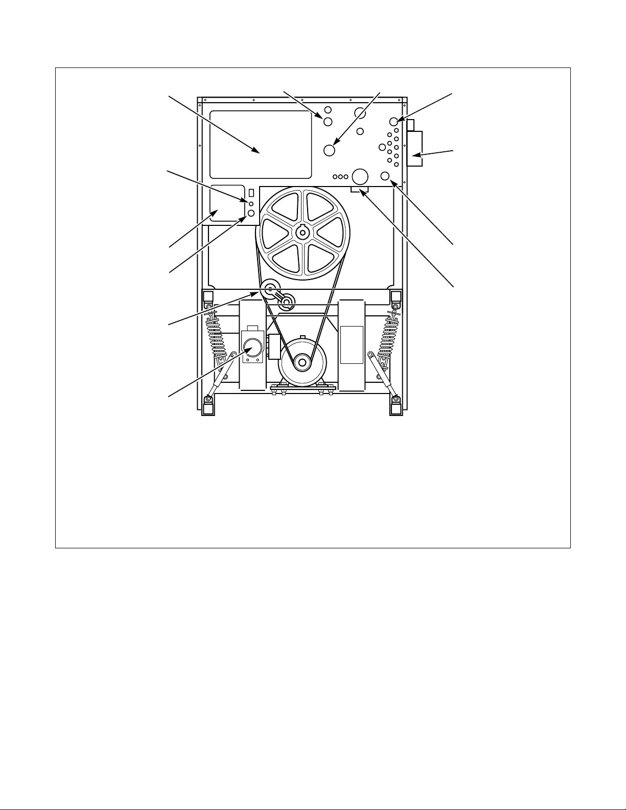
Operation
12
11
10
1
2
3
4
5
9
6
8
7
CFS228R
1 Cold Water 7 Drain Valve
2 Vent 8 Idler Pulley
3 Hot Water 9 Power Cable Connection
4 Liquid Supply Connections 10 Terminal Block
5 Steam Connection 11 Liquid Supply Control
6 Vacuum Breaker 12 AC Drive Box Enclosure
Figure 2
CFS228R
F232059
© Copyright, Alliance Laundry Systems LLC – DO NOT COPY or TRANSMIT
11
Page 14

Operation
Theory of Operation
The design of the washer-extractor emphasizes
performance reliability and long service life. The
cylinder, shell, and main body panels are fabricated of
stainless steel.
Electrical controls for the washer-extractor are housed
in separate enclosures. The front control module
houses the WE-6 microcomputer, the fuse/relay board
together with its interface board, water level switches,
a motor thermal overload reset switch, and other
control components. The rear control module houses
the AC inverter drive and its components.
All variable-speed freestanding machines use the AC
inverter drive control, which provides programmable
motor speeds using a single motor. The AC drive
interface board converts motor logic from the WE-6
microcomputer to the correct signals for the AC
inverter drive. In addition, all logic inputs to the
computer are routed through this board.
The cylinder is supported by roller bearings housed
inside a trunnion.
The cylinder is constructed with four lifters or ribs that
lift the laundry from the bath solution when the
cylinder rotates at slow speed and then allow the
laundry to tumble back into the bath. This mechanical
action accomplishes the washing function. The
cylinder is perforated, allowing the water to drain from
within during the wash and extract steps.
Water enters the machine through electromechanical
water valves controlled by the microcomputer. The
microcomputer also controls the drain and door lock.
In addition, it selects the water levels according to the
programmed cycle. Vacuum breakers are installed in
the water-inlet plumbing to prevent backflow of water.
A door-lock system prevents opening of the stainless
steel door when a cycle is in progress. It also prevents
operation of the washer-extractor when the door is
open.
The doorbox contains the Hall-effect door-locked and
door-closed sensors and the door-unlock solenoid.
The supply dispenser is located on the left side of the
front of the washer-extractor. The dispenser has five
supply compartments, numbered 1 to 5 from left to
right. The compartments hold supply cups that are
used for either liquid or dry supplies. A nozzle flushes
supplies from the cups with water for the time
programmed in the cycle.
Liquid supplies can be injected directly into the cups
by a customer-supplied external chemical supply
system. Five hose barbs on the rear of the washerextractor facilitate connection to an external supply
system.
Emergency Stop Button
A red emergency stop button is located on the upper
right-hand corner of the control panel. Push the button
in to stop the washer-extractor. Turn button to the left
and pull out to reset.
Wet Clean Features
The washer-extractor is equipped with the following
wet clean capable features: One-half wash speed
allows gentle mechanical action during wash. Eight
supply signals provide not only normal laundering
signals to dispense detergents, bleaches, softeners,
sours, etc., but also chemicals unique to wet clean
processing.
Motorized drain valves hold water in the machine
during the wash, soak, and rinse steps. The drain valve
is normally open, which means that it closes only
when power is applied, thus allowing the machine to
drain in the event of a power failure.
12
© Copyright, Alliance Laundry Systems LLC – DO NOT COPY or TRANSMIT
F232059
Page 15

Operation
Wet Clean Capabilities
Differences in WE-6 prompt (setup) options
The WE-6 software provides the usual setup options:
● Degrees F or C
● One or Two drain
● Advance or No Advance
● Manual or No Manual
● Balance setting
In addition, the software provides a new selection: Wet
Clean/No Wet Clean. The wet clean/no wet clean
option enables or disables wet clean functions. In
summary then, the prompt (setup) options are now as
follows:
● CEN/FAR
● 1DRAIN/2DRAIN
● ADV/NO ADV
● MANUAL/NO MAN
● WET CL/NO WCL
● BAL SW, BAL 1, BAL 2, BAL 3
Wet Clean Functions
Wet clean functions include a reduced wash speed
capability and a recirculation pump capability. These
functions are enabled by the WET CL/NO WCL
prompt selection. Other wet clean features are
permanently enabled, and can be used for other
applications as well. In particular, extra supply
capability (up to eight supplies, in two banks of four
supplies), and additional agitation actions as outlined
below.
Agitations:
● Wash 1 – normal: 18 seconds forward / three
seconds off / 18 seconds reverse / three seconds
off; repeat
● Wash 2 – gentle: three seconds forward /
27 seconds off / three seconds reverse / 27
seconds off; repeat
● Wash 3 – no rotation
● Wash 4 – ten seconds forward / 20 seconds off /
ten seconds reverse / 20 seconds off; repeat
● Wash 5 – uses most recent agitation; defaults to
Wash 1 agitation
● Wash 6 – super gentle: four seconds forward /
56 seconds off / four seconds reverse / 56 seconds
off; repeat
● Wash 7 – no rotation; drain 1 (sewer drain) open;
no attempt to refill to level
F232059
© Copyright, Alliance Laundry Systems LLC – DO NOT COPY or TRANSMIT
13
Page 16

Operation
Using the auxiliary 1 (A1) and auxiliary 2 (A2)
outputs for wet cleaning
The A1 and A2 outputs (so labeled on the solid state
WE-6 output PC board) can be made to operate as
timed outputs, or to remain on until a drain step.
Reduced wash speed
Normally, the A1 output would govern optional
reduced wash speed. This means that if the WE-6 is
prompted for “WET CL”, and then an auxiliary 1 “A1”
step is programmed for any amount of time (one
second is a good choice for time in the event of
controlling reduced wash speed), the A1 output will
remain on until a drain step, or until Stop routine.
Thereby the reduced wash speed remains in effect as
long as A1 remains on.
For example, with “WET CL” prompt selected, a
Wash 1 agitation is wanted, but at reduced wash speed.
Program auxiliary 1 step for one second, then program
a Wash 1 step. The A1 output will remain on during
the Wash 1 step, selecting reduced wash speed during
the Wash 1 step. Upon reaching a drain step, or upon
entering the Stop routine, the WE-6 will operate the
machine at reduced wash speed (PROVIDED the
machine is equipped with the necessary hardware for
controlling reduced wash speed).
Control of an optional recirculation pump
The A2 output will also remain on until a drain or the
Stop routine if the WE-6 prompt is “WET CL” and if
“1DRAIN” is selected. This would allow control of an
optional recirculation pump by permitting the pump to
continue operating during a wash step. For this
control, program an auxiliary 2 “A2” step for one
second or other suitable time, and the output would
remain on until a drain step or until the Stop routine.
The auxiliary 2 step would also go off upon entering a
Wash 7 step.
Note that “2DRAIN” prompt will OVERRIDE wet
clean control of auxiliary 2 output. If “2DRAIN” is
selected that means that the auxiliary 2 output is
reserved for controlling a second independent drain
(not for integrated reuse – you should select
“1DRAIN” for integrated reuse). Also, if “2DRAIN”
is selected. the WE-6 will not permit programming an
auxiliary 2 step.
14
© Copyright, Alliance Laundry Systems LLC – DO NOT COPY or TRANSMIT
F232059
Page 17
Operation
WE-6 Microcomputer
The WE-6 microcomputer control is a fieldprogrammable solid-state control capable of storing
and running up to 39 preprogrammed ready-to-use
cycles.
Cycle 01 is a test cycle used to verify proper operation
of the machine. With the exception of Cycle 39, the
remaining cycles are complete wash cycles or
specialty cycles designed to handle various fabrics at
specific water temperatures and levels. Cycle 39 is
designed to test an external chemical injection supply
system.
A detailed description of the cycles can be found in the
Programming section of this manual under
Preprogrammed Cycles. (If this washer-extractor’s
computer has been equipped with special
preprogrammed cycles, a separate insert listing these
cycles has been included in the resealable plastic bag
which contained this manual.)
Never turn the power off while the computer mode
switch is in the PROGRAM position. Such action will
disorder portions of the programmed data,
necessitating reprogramming of some or all of the
existing cycles. Always return the mode switch to
RUN position before turning the power off.
LED Display
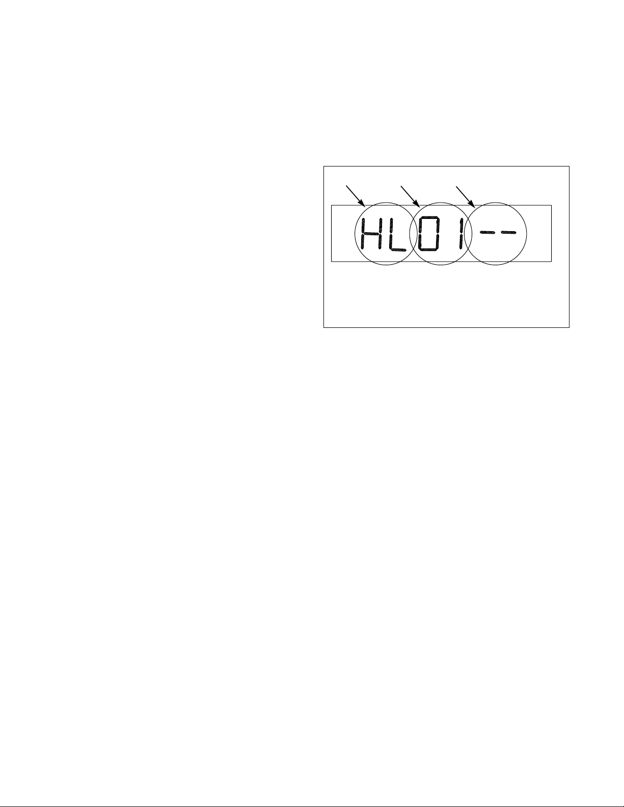
The WE-6 microcomputer has a six-digit LED display.
References to display indications pertain to the first
four digits of the display, reading left to right. The last
two digits on the right side of the display will indicate
either the last cycle used or the current cycle in
progress. Refer to Figure 3.
1
1 Function Being Executed
2 Step Number
3 Cycle Number
2
3
U151R
Figure 3
Never leave the mode switch key inserted in the switch
lock where it may be accessible to unauthorized
personnel not familiar with programming procedures.
The computer control in this washer-extractor is
continuously on the alert for problems within the
machine. When the computer detects a problem, it
immediately flashes a letter or number or both on the
display. It may activate the signal buzzer as well.
F232059
© Copyright, Alliance Laundry Systems LLC – DO NOT COPY or TRANSMIT
15
Page 18

Operation
Table 1 lists the various displays and what they mean.
The last digit represents version number.
The operator should become familiar with these
computer displays.
Display Interpretations
Display Meaning Display Meaning
FRWC00 Program identification code (ROM). CY Cycle number
D1 Drain #1
Error Messages Da Drain to optional reuse tank A
FILL Fill problem Db Drain to optional reuse tank B
EMTY Empty problem DONE End of cycle
TEMP Over-temperature-limit condition EXISTS Cycle already in memory
ME Cycle information problem EDIT? Do you want to edit the cycle?
WATER Water in washer-extractor at end of cycle F Heat select temperature in ° Fahrenheit
DOOR Door not locked problem C Heat select temperature in ° Centigrade
OVERHT Open or shorted temperature input circuit or
temperature out of computer’s allowable
limits
aL Fill from reuse tank A to low level HM Hot fill to medium level
HH Hot fill to high level
HL Hot fill to low level
aM Fill from reuse tank A to medium level HO Hot fill to overflow
aH Fill from reuse tank A to high level HT Heat (steam or electric)
bL Fill from reuse tank B to low level H1 High speed #1
bM Fill from reuse tank B to medium level H2 High speed #2
bH Fill from reuse tank B to high level H3 High speed #3
A1 Auxiliary output #1 MS Medium speed spin
A2 Auxiliary output #2 --M Minutes (used when programming time)
A3 Signal --S Seconds (used when programming time)
CH Cold fill to high level NCYC Cycle not available
CM Cold fill to medium level NEXT Select cycle or open door or select program
CL Cold fill to low level SDLY Spin coast delay
CO Cold fill to overflow SK Soak
Table 1
16
© Copyright, Alliance Laundry Systems LLC – DO NOT COPY or TRANSMIT
F232059
Page 19

Operation
Table 1 (Continued)
Display Interpretations
Display Meaning Display Meaning
STOP Stop button pressed or cycle ended WE-6 Prompts
S1 Supply #1 (Detergent) °FAR Temperature in degrees Fahrenheit
S2 Supply #2 (Bleach) °CEN Temperature in degrees Centigrade
S3 Supply #3 (Sour) 1DRAIN One drain capability selected. (This means
that a second independent drain controlled by
Auxiliary 2 output is disabled.)
S4 Supply #4 (Softener) 2DRAIN Second independent drain enabled (via
S5 Supply #5 (Starch/Sizing)
TH Controlled temperature fill to high level
TM Controlled temperature fill to medium level
Auxiliary 2 output – precludes control of
recirculation pump via Auxiliary 2, if
selected). This should not be confused with
the “dual drain” option.
TL Controlled temperature fill to low level ADV Advance (skip steps) feature enabled
TO Controlled temperature overflow NO ADV Advance feature disabled
WH Warm fill to high level MANUAL Manual Mode enabled
WM Warm fill to medium level NO MAN Manual Mode disabled
WL Warm fill to low level
WO Warm fill to overflow level
W1 Wash 1 (regular reversing)
WET CL
Wet clean function for Auxiliary 1 output
(1/2 wash speed) and Auxiliary 2 output
(recirculation pump) enabled. (Refer to
“2DRAIN”.)
W2 Wash 2 (gentle reversing) NO WCL Wet clean function for Auxiliary 1 and 2
W3 Wash 3 (no agitation)
disabled (Auxiliary 1 and 2 are timed outputs.
W4 Wash 4 (medium reversing action) BAL SW Balance sensor
W5 Wash 5 (temp.-controlled cool-down) BAL 1 Balance routine for 35 pound and 50 pound
capacity
W6 Wash 6 (extra low agitation) BAL 2 Balance routine for 85 pound and 135 pound
W7 Wash 7 (no agitation, drain 1 open, no refill)
capacity
• Left dot – poor balance condition BAL 3 Balance routine for 250 pound capacity
• Second dot from left – door lock switch
• Third dot from left – Program Mode RL Fill from optional extra fill inlet to low level.
• Fourth dot from left – high level reached RM Fill from extra fill inlet to medium fill.
• Fifth dot from left – medium level reached RH Fill from extra fill inlet to high level.
F232059
• Right dot – low level reached DRTEMP Temperature is above 160°F in drain to reuse
tank A or B step.
© Copyright, Alliance Laundry Systems LLC – DO NOT COPY or TRANSMIT
17
Page 20

Operation
Operational Keypad
These functions are available to the operator and are
intended to control operation of the washer-extractor.
The computer’s control keypad includes sixteen keys.
Refer to Ta b le 2.
Refer to Figure 4. Fourteen of these keys list functions
printed in black lettering on a silver background.
Operational Keypad
Key Description
Numbers 0-9 Press to select cycle number
Display Temp Press and hold. Display will show and update sump temperature in degrees Fahrenheit or Centigrade.
Advance Press to cause computer to skip to the next step in the cycle. The computer will not advance past drain
step. (The Advance key is enabled at the factory and can be disabled at the laundry site.)
Stop Press to immediately abort the cycle and initiate the Stop routine
Start Press to start selected cycle or to restart a step following a “FILL” or “EMTY” alarm. Refer to Error
Recovery Routine.
Manual Refer to Manual Mode Control Feature.
Table 2
18
© Copyright, Alliance Laundry Systems LLC – DO NOT COPY or TRANSMIT
F232059
Page 21
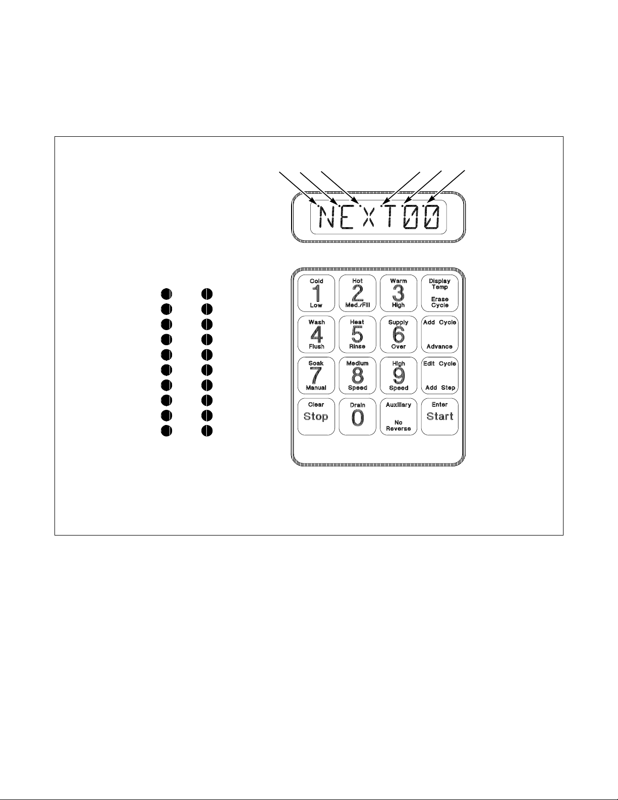
Located to the left of the computer keypad
are 20 LED indicator lights for the computer outputs.
During the time that a cycle is running, one or more of
these lights will be on to indicate the outputs activated
for a particular step. Refer to Figure 4.
Operation
Output Indicators
Supply 1
Supply 2
Supply 3
Supply 4
Supply 5
Cold Fill
Hot Fill
Spare
Spare
Signal
Heat
Forward
Reverse
Dist. Speed
Med. Speed
High Speed
Unlock Door
Drain Closed
Auxiliary 1
Auxiliary 2
3
2
1
4
6
5
1 Balance Sensing Indicator 4 High Level Fill Indicator
2 Door Lock Switch 5 Medium Level Fill Indicator
3 Program Mode 6 Low Level Fill Indicator
Figure 4
U152R
U152R
F232059
© Copyright, Alliance Laundry Systems LLC – DO NOT COPY or TRANSMIT
19
Page 22
Operation
Start-Up
Turn on the main power source (circuit breaker or cutoff switch on the wall).
When AC power is turned on, the front panel display
will show the program (ROM) identification code.
This identification code will appear for approximately
five seconds. Then the computer display will flash
“POWER” and “WA I T ” alternately for two minutes.
The display will then show “NEXT00” to indicate that
a cycle can be selected. This display will be shown at
all times that power is on between cycles, indicating
that the door-unlock solenoid will function if the doorunlock button is pressed. The washer-extractor is then
ready for loading and unloading.
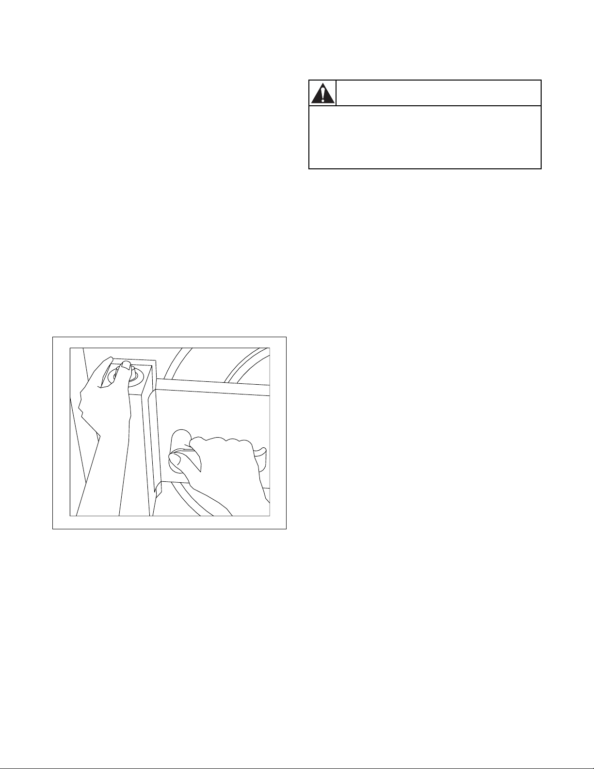
Opening Door
Use left hand to press and hold the door-unlock button
located on the top of the doorbox cover. Use right hand
to turn door handle upward and swing the door right to
open. Refer to Figure 5.
Loading
CAUTION
Be careful around the open door,
particularly when loading from a level
below the door. Impact with door edges
can cause personal injury.
SW025
Load the washer-extractor to full capacity whenever
possible, but do not exceed the rated dry-weight
capacity of the machine if the fabric to be washed is
quite dense, closely woven, and heavily soiled.
Overloading can result in an inferior wash. The
operator may need to experiment to determine load
size based on fabric content, soil content, and level of
cleanliness required.
Partial loads can cause greater machine wear than full
loads. Partial loads, if necessary, should only occur at
the end of the day.
When loading is complete, ensure that all fabric is
inside the basket. Then close and lock the door.
Figure 5
NOTE: When washing items which may
disintegrate or fragment, such as mop heads or
sponges, use laundry nets to prevent drain
blockage.
U153R
U153R
20
© Copyright, Alliance Laundry Systems LLC – DO NOT COPY or TRANSMIT
F232059
Page 23

Operation
Supply Dispenser
Dry supplies are placed in the supply dispenser
compartment cups prior to the start of each cycle.
Liquid supplies can be injected directly into the supply
dispenser by an external chemical supply system.
Supply dispenser compartment cups must not be
removed when an external chemical injection supply
system is attached to the washer-extractor.
Cycle Selection
NOTE: Press keys at their centers just hard enough
to activate them.
Find the cycle number of the desired wash cycle from
the Standard Cycle Charts in the Programming
section of this manual. Cycle numbers must be twodigit numbers from 01 to 39.
Press the numbers desired on the keyboard and note
that these numbers are displayed after “NEXT”.
When keys are pressed on the keyboard, a beep will be
heard. If an error is made, press the numbers again. As
numbers are entered, they move from right to left on
the display.
To begin the cycle at any step other than the first step,
press the Advance key to advance through the cycle to
the desired starting point. (The Advance key is enabled
at the factory and can be disabled at the laundry site.)
Then press the Start key.
It is possible to skip to the next step in a cycle, with the
exception of a drain step; drain steps must be allowed
time to complete.
When the display shows the step desired to begin the
cycle, press the Start key.
If the door is not locked, the display will indicate
“CLOSE” and “DOOR”. If this occurs, be sure the
door is closed and locked and press the Start key again.
If the LED indicator lights for the computer outputs
indicate that one or more outputs are activated but the
washer-extractor is not functioning according to the
output or outputs indicated, contact a service
technician.
As water fills the washer-extractor, one or more of the
indicator lights located to the left of the keyboard will
come on and stay on until the required water level is
reached. LED dots located in the upper left corner of
the last three digits on the right of the display will
illuminate to indicate the water level(s) reached:
NOTE: If the washer-extractor is equipped with
both steam and electric heat, the selector switch on
the valve panel must be in the correct position for
the desired heat source, down for steam heat, up for
electric heat.
Cycle Execution
To start the selected cycle, press the Start key. If the
selected cycle number is not in the computer memory,
the display will show “NCYC”. If this happens, select
another cycle. Otherwise, the display will now show
the first step. For example, if the display reads
“HL01”, “HL” represents a hot fill to low level, and
“01” indicates that this is the first step of the cycle.
As the cycle proceeds, the display will show the
function being executed, the step number, and the
cycle number selected. Pressing the Edit Cycle key
while the cycle is running will cause the display to
show the remaining cycle time in minutes. Pressing
this key again will return the display to normal.
● When the indicator dot in the last digit on the
right is lit, the low water level has been reached.
● When the dot in the next-to-the-last digit is lit,
medium water level (optional) has been reached.
● When the dot over the third digit from the right
has been lit, high level has been reached.
The cycle will continue until its completion. Then the
display will show “DONE”.
F232059
© Copyright, Alliance Laundry Systems LLC – DO NOT COPY or TRANSMIT
21
Page 24

Operation
Test Cycle
Cycle number 01 is a test cycle used to analyze
washer-extractor functions. Refer to the Programming
section of this manual.
Step 01 in cycle number 01 is a cold fill to low level.
This step is designed to give not quite enough time to
complete a fill, causing the display to read “FILL”.
Press the Start key to continue the fill, and the test
cycle will proceed.
Step 02 in the test cycle is a drain step. Again, the time
allotted is shorter than it would be in a normal cycle.
The display will read “EMTY”. To proceed, press the
Start key.
The steps in the test cycle are relatively short, with the
exception of steps 03, 20, 22, 24, 25, 26, and 29. These
can be shortened by pressing the Advance key to go on
to the next step.
The operator may skip to any next step in the cycle
with the exception of a drain step: Drain steps must be
allowed to complete. To skip forward in the test cycle,
press the Advance key.
Wet Clean Testing
Wet clean processing outputs are tested through the
energizing of the Auxiliary 1 output in step 17 and
Auxiliary 2 output in step 18. Steps after step 28 are
designed to test water reuse processing, if this option
is installed. If it is not, press the Stop key to abort the
cycle.
NOTE: Prompts for “1DRAIN” and “WET CL”
must be selected when prompting the WE-6
microcomputer in order for steps 17 and 18 to
work properly for wet clean processing.
NOTE: The Advance feature may be disabled.
Refer to System Programming in the Programming
section of the manual.
22
© Copyright, Alliance Laundry Systems LLC – DO NOT COPY or TRANSMIT
F232059
Page 25

Operation
NEVER insert hands or objects into
basket until it has completely stopped.
Doing so could result in serious injury.
SW012
WARNING
Stop Routine
The operator can select the agitation which will be in
effect for the entire Stop routine. This will help
prevent tangling of the load and provide maximum
control. Three agitations are available for the Stop
routine. They are as follows:
Wash 1
● 18 seconds forward
● 3 seconds pause
● 18 seconds reverse
● 3 seconds pause
● sequence repeated
Wash 2
● 3 seconds forward
● 27 seconds pause
NOTE: The forward and reverse times differ
slightly for the Wash 1 selection. These times give
the best results during the Stop routine when no
water is in the washer-extractor.
To select the agitation in the Stop routine, program a
Wash 1, 2, or 3 step for 1 second. The washer-
extractor will begin refilling to the most recent water
level if the time is more than 1 second. If the most
recent wash type was Wash 4, 6, or 7, the WE-6 will
default to no agitation (Wash 3) during the Stop
routine.
NOTE: If the desired action is not programmed in
the final cycle step, the computer will default to the
most recent action in the cycle. If the cycle stops
prematurely, the most recent action at the time the
cycle is interrupted will be in effect during the Stop
routine.
The display will read “W1-cc”, “W2-cc”, or “W3-cc”
for Wash 1, Wash 2, or Wash 3 action during the entire
Stop routine until the final 10 seconds. (The “cc” here
stands for the current cycle number and will be
represented by numbers in the actual display.) During
the final ten seconds, the display reads “STOPcc”. The
display will then read “DONEcc”. At that point, the
door can be opened.
● 3 seconds reverse
● 27 seconds pause
● sequence repeated
Wash 3
● no agitation
F232059
© Copyright, Alliance Laundry Systems LLC – DO NOT COPY or TRANSMIT
23
Page 26

Operation
Balance Detection
The washer-extractor may be equipped with either of
two balance detection systems: (1) a balance sensor
detection system or (2) an inverter drive balance
detection system.
Balance Sensor Detection
If the washer-extractor is equipped with the balance
sensor detection system, the optical sensor installed on
a bracket on a shock absorber signals the computer to
slow the washer-extractor when an out-of-balance load
occurs during extract.
If the balance sensor is tripped, the out-of-balance
LED indicator located in the upper left corner of the
first digit of the display will light and will remain
lighted until the end of the extract step. This indicator
tells the operator that an out-of-balance condition
existed during an extract step. The washer-extractor
will attempt to balance three times during an extract
step.
If on the third attempt the out-of-balance condition
continues, the washer-extractor will advance to the
next step. (If the next step is another spin step, it will
be skipped also.)
Inverter Drive Balance Detection
If the washer-extractor is equipped with the inverter
drive balance detection system, balance is detected by
the inverter drive during a drain step as opposed to an
extract step. The WE-6 microcomputer will make up
to seven attempts to balance the load during a drain
step. During the final balance attempt, the out-ofbalance LED indicator located in the upper left corner
of the first digit of the display will light. The indicator
will remain lighted until the drain step is complete.
If on the seventh attempt the load is not balanced, the
washer-extractor will continue to the next step in the
cycle following the drain step that is not a spin step.
Therefore, if one spin step or two or more consecutive
spin steps follow, all will be skipped if seven attempts
to balance the load in the drain step fail. High speed
steps include medium, H1, H2, and H3 spin steps.
NOTE: The computer cannot advance through a
drain step, nor will the computer allow starting a
cycle in a spin step.
NOTE: A drain step must be programmed prior to
a high speed step to allow for inverter drive balance
detection. Otherwise, spin steps will be skipped by
the computer.
If the washer-extractor is equipped with the inverter
drive balance detection system, a special balance
switch serves to remove power to the machine. This
means that if the washer-extractor balance “passes” the
inverter drive balance detection system at the drain
step but the balance switch detects an out-of-balance
load condition at the extract step, power will be
removed from the washer-extractor.
At this point, the LED display goes blank on the WE-6
microcomputer, and the washer-extractor coasts to a
stop. Such a condition indicates a serious problem.
Contact a service technician before attempting to
restore power to the washer-extractor.
24
© Copyright, Alliance Laundry Systems LLC – DO NOT COPY or TRANSMIT
F232059
Page 27

Operation
Temperature Display
The temperature display can be prompted to display in
Fahrenheit or Centigrade. Refer to System
Programming in the Programming section of this
manual.
To display temperature, press the Display Temp key.
The display will read “F” or “C” and the temperature
as long as the key is pressed. The computer will update
the display automatically.
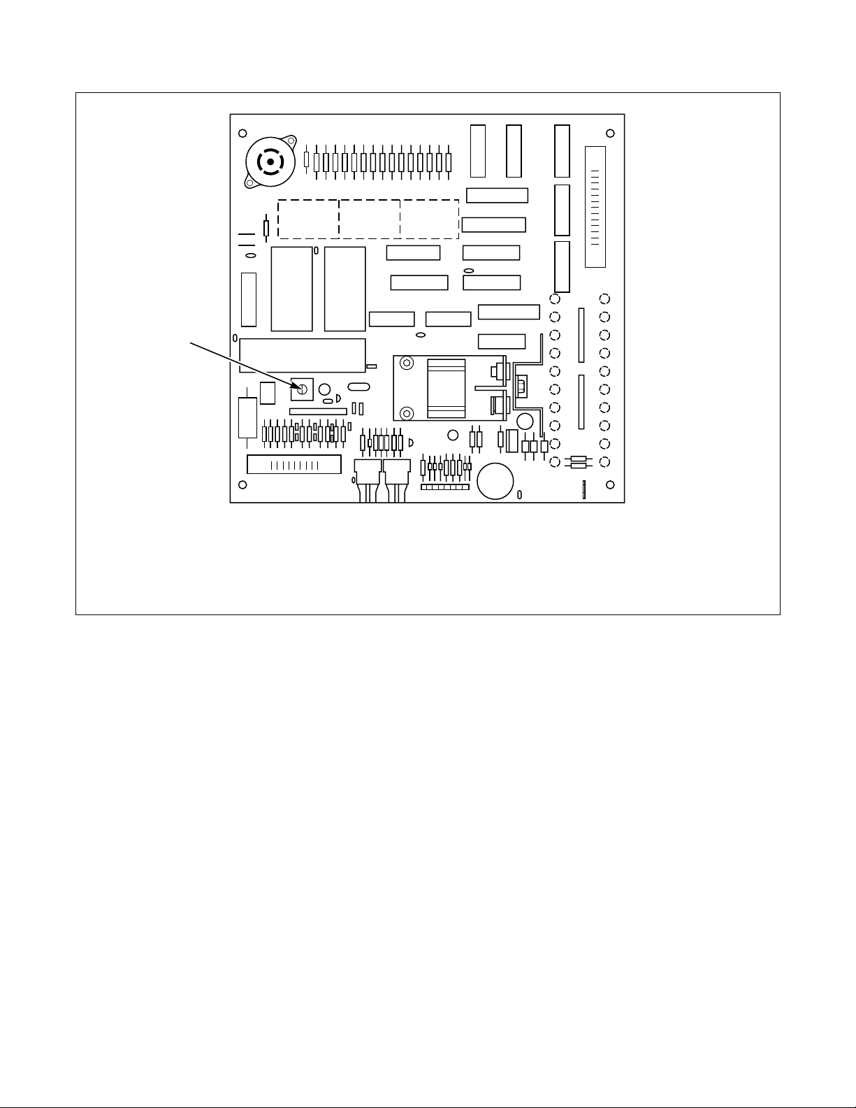
Calibrating the WE-6 Temperature Circuit
1. Open the control compartment to gain access to
the WE-6 computer board.
2. Viewing the WE-6 computer board from the rear,
locate the blue rectangular plastic component
with a white plastic screw head in the center. This
is the temperature calibration potentiometer.
Turning this screw head adjusts the temperature
reading.
3. Fill the machine sump with water and place an
accurate temperature sensor in the water to
provide a measurement of the actual water
temperature. The WE-6 temperature readout is
then adjusted to match this to the nearest unit. It
is easiest to program a Wash 3 (no agitation) for
10 seconds (to prevent rotation and subsequent
damage to the temperature sensor), then a cold
fill to high level, followed by a Wash 3 for
9 minutes and 99 seconds. Do not press STOP.
Calibration must be completed before the last
wash step finishes. Remove power to machine
after calibration until computer goes off to
prevent rotation when the cycle ends.
4. Start the cycle. When the water level is reached
(and the external temperature sensor is
submerged), press the DISPLAY TEMP key on
the WE-6 keypad. The display will show a
reading in either degrees F or degrees C, or the
conversion will have to be made by calculation as
follows:
Degrees F = (Degree C x 9/5) + 32
Degrees C = (Degrees F - 32) x 5/9
5. While pressing the DISPLAY TEMP key, use the
screwdriver to turn the temperature calibration
screw until the WE-6 displays the same
temperature as the external sensor, which should
be accurate at least to the nearest degree. Turning
the screw clockwise increases the displayed
temperature.
6. When the temperatures match, calibration is
completed. Close the control compartment and
remove the external temperature sensor. To
prevent rotation, DO NOT PRESS STOP; instead
remove power to the machine until the computer
goes off.
*As an alternative, if an external sensor is not
available, measure the temperature of the inflowing
water, and follow step 5.
F232059
© Copyright, Alliance Laundry Systems LLC – DO NOT COPY or TRANSMIT
25
Page 28
Operation
BEEPER
ROM
1
J2
1 Temperature Calibration Adjustment
EE ROM
BATTERY
BACKUP
J3
WE-6 CONTROL BOARD
J1
J5
CFS442N
NOTE: Control board shown is WE-6 washer unit. Board for simulator does not have battery backup. Washer and
simulator boards are not interchangeable.
Figure 6
26
© Copyright, Alliance Laundry Systems LLC – DO NOT COPY or TRANSMIT
F232059
Page 29

Operation
Error Recovery Routine
When the computer detects an error, it will stop
running the current step and display a message to
indicate what type of error was found:
● “FILL” indicates that the washer-extractor did
not fill within the allotted time.
● “EMTY” indicates that the washer-extractor did
not drain in the allotted time.
● “TEMP” indicates that the temperature sensor
has recognized an over-temperature-limit
condition.
● “ME” indicates that the computer has detected a
problem with the cycle information. The cycle
must be edited.
● “WATER” indicates that the WE-6
microcomputer senses low, medium, or high
water level at the end of the Stop routine.
● “DRTEMP” indicates that the WE-6 has detected
water temperature over 160°F (71°C) in a “drain
to reuse” step. Instead of draining to a tank, the
computer gives this error message. The cycle
must be edited so the temperature is below 160° F
(71°C) upon entering a reuse drain step (“Da” or
“Db”).
All outputs remain off while the message
displays, and the door cannot be unlocked.
NOTE: The WE-6 microcomputer will not allow
the door to be opened while there is water in the
washer-extractor.
Each of these errors is considered to be recoverable.
The operator has two minutes to respond to the error
condition (except in the case of “WATER”). During
this time, the computer will turn the signal (buzzer)
relay on and off at the rate of one second on and one
second off to alert the operator to the error condition.
The washer-extractor may be restarted by pressing the
Enter key. Pressing the Enter key will restart the cycle
step for the originally programmed time period. The
cycle may be aborted by pressing the Clear key. After
aborting the cycle, the computer will go to the normal
stop routine. If the operator does not respond to the
error condition within the allocated two minutes, the
computer will automatically abort the cycle.
NOTE: The “TEMP” alarm can be recovered only
after the temperature falls below the alarm level.
Certain error conditions are considered to be nonrecoverable:
● If the door opens during a cycle, the computer
will display “DOOR”. The operator must close
the door.
Then, after the computer has detected that the
door is closed, it will automatically abort the
cycle and go to the normal Stop routine.
● “OVERHT” will be displayed when the computer
detects an open or shorted temperature input
circuit or temperatures are outside of the washerextractor’s allowable limits. Contact a service
technician.
F232059
© Copyright, Alliance Laundry Systems LLC – DO NOT COPY or TRANSMIT
27
Page 30

Operation
Thermal Overload Indicator
To protect the AC drive from damage due to excessive
temperature, a thermal limit switch is embedded in the
drive box.
If the thermal limit switch is tripped due to damaging
conditions, the “Drive Thermal Indicator” light located
in the WE-6 control module will light and power will
be removed from the drive. The AC drive thermal limit
switch MUST be manually reset. Refer to the
following for location and instructions.
Before resetting the thermal overload switch,
determine the reason for the overload. The following is
a partial list of possible problems:
● Bad motor bearings.
● Motor cooling fan blocked or not operating.
● Excessively dirty motor (lint build-up, for
example).
● Room temperature higher than 104°F (40°C).
● Dirty fan filter.
● Fan not operating properly.
Resetting Thermal Overload Switch
1. Remove the main power from the machine.
2. Locate the AC drive box and remove the cover.
The AC drive box enclosure is located at the rear
in the upper, left-hand corner of the machine as
seen from the rear.
3. Locate the thermal limit switch in the AC drive box
and press the red reset button located on the switch.
The thermal limit switch is mounted in the center
of the left side wall of the AC drive box.
4. Replace the cover and return power to the
machine.
● Fan not installed properly.
28
© Copyright, Alliance Laundry Systems LLC – DO NOT COPY or TRANSMIT
F232059
Page 31

Operation
Manual Mode Control Feature
With the exception of a spin or drain step, manual
control is available only while a preprogrammed cycle
is in progress, and if Manual Mode is prompted in the
WE-6 programming. Except for the motor outputs and
door unlock output, the WE-6 microcomputer outputs
can be operated manually from the keypad. (In order to
ensure proper sequencing, motor speeds are always
controlled by the computer.)
In normal operation, when the Program Mode switch
is in the RUN position, only the operations printed in
black on the keys are accessible to the operator.
NOTE: When the Manual Mode control feature is
activated, the operator must supply on/off
commands for the controllable outputs. If an
output is on, it will remain on until turned off by
the operator or until the assigned time for the
Manual Mode expires. This can be as long as
9 minutes and 99 seconds.
During the Manual Mode, normal cycle timing is
suspended. When the Manual Mode is entered, the
operations printed in red on the keys and mentioned in
the following discussion are activated.
Entering the Manual Mode during a fill operation is
not recommended. This bypasses the water-level
switch inputs, and the water must be turned off
manually by the operator.
When the computer receives all these inputs within the
three-second time limit, it will enter the Manual Mode
for the time assigned.
The computer display will flash between “MAN230”
(reflecting the time chosen in step 2 of the above
procedure) and the current cycle step display for four
seconds.
After four seconds, the display will flash between
“MANUAL” and the current cycle step display for the
remainder of the assigned time.
Manual Mode operation will automatically end when
the assigned time elapses. Normal program timing will
then resume from the same point in the cycle where
the Manual Mode was entered. To exit the Manual
Mode and return to normal program timing before the
assigned time elapses, press the Start key.
All water fill valves, supplies, heat (if the machine has
reached low water level), main drain valve (Drain 1)
and auxiliary outputs (excluding water reuse control
outputs) can be manually controlled. The heat and
drain outputs require that only one key be pressed
(Heat and Drain respectively). All other outputs
require that two keys be pressed. For example, to turn
on the cold fill valve, press the keys Cold and Fill.
When an output is on, pressing the same key or keys
which caused it to energize will turn it off. Thus, to
turn off the cold fill valve, press the keys Cold and Fill
once again.
The following procedure must be accomplished within
three seconds in order to enter the Manual Mode:
1. Press the Manual key.
2. Then press three number keys to assign a time in
minutes and seconds to the Manual Mode. For
example, press key 2, key 3, and key 0 to enter
the Manual Mode for 2 minutes and 30 seconds.
3. Then press the Add Step key.
F232059
© Copyright, Alliance Laundry Systems LLC – DO NOT COPY or TRANSMIT
29
Page 32

Notes
30
© Copyright, Alliance Laundry Systems LLC – DO NOT COPY or TRANSMIT F232059
Page 33

Programming
Programming Keypad
function keys in the Program Mode. In each instance
(with the exception of the Warm/High key), when a
All sixteen keys are used in the Programming Mode.
Specific functions are printed in red on the keys. The
Programming Mode is active only when the Program
Mode switch is in the PROGRAM position. (When
programming is complete, remember to return the
key is first pressed in a programming step, the word
printed at the top of the key applies. In most instances,
the next time the same key is pressed – or if another
key has been pressed in the interim – the word printed
on the bottom of the key applies.
mode switch to the RUN position and remove the key.)
Keys 1-6 and the Auxiliary/No Reverse key are dual
Programming Keypad
Red Keys Description
Cold
Low
Hot
Med./Fill
Warm
High
Erase Cycle Erase Cycle and a two-digit cycle code number are pressed to erase a cycle from memory.
Wash Wash is pressed when the step is a wash or dilution rinse. Then key 1, 2, 3, 4, 6, or 7 is pressed to
Cold is pressed when the step requires cold water.
Low is pressed for low-level fill.
Hot is pressed when the step requires hot water.
Med./Fill is pressed to select medium water level.
Fill is pressed in the Manual Mode to operate fill valves.
Warm is pressed when the step requires warm water.
High is pressed for high-level fill.
choose the type of agitation.
Heat Heat is pressed when auxiliary heat is needed. This must be followed by a specific temperature
selection, such as 165°F. The temperature must be entered; then a time assigned to reach that
temperature must be entered.
Supply
Over
Add Cycle Add Cycle is pressed to begin the process of programming a new cycle into memory.
Soak Soak is used when no agitation is desired. This follows a fill and/or supply step. The time must be
Medium Speed Medium Speed is pressed when a medium spin only is desired for washing delicate items not suited
High Speed High Speed is pressed when a fast spin is desired. Pressing the High Speed key once will activate the
Edit Cycle
Add Step
Clear (black on
red background)
Supply is pressed when soap, bleach, or other chemicals are desired. Key 1, 2, 3, 4, or 5 must then be
pressed to indicate the specific supply dispenser being used. Combinations of these supplies can be
programmed. Refer to Programming a Supply Step.
Over is pressed when an overflow of water is desired. The drain is closed and water is added without
regard to level. Water flows out the overflow connection for the time assigned to the step.
assigned in hours and minutes. (Wash 3 also provides no agitation.)
for high-speed spin or when an intermediate spin is desired.
H1 spin; twice, the H2 spin; and three times, the H3 spin.
Edit Cycle is pressed followed by a two-digit cycle code number to display the steps of a
preprogrammed cycle. The cycle may be altered during the edit cycle procedure by deleting, changing,
or adding steps.
Add Step is pressed to add a step to an existing cycle during the edit cycle procedure.
Clear is pressed when an error has been made in programming a step. Instead of pressing Enter as the
step is completed, press Clear to eliminate the incorrect information. (Clear should never be pressed
when displaying a cycle unless a particular step is to be eliminated or changed. Refer to Displaying a
Cycle in Memory.
F232059
© Copyright, Alliance Laundry Systems LLC – DO NOT COPY or TRANSMIT
31
Page 34

Programming
Programming Keypad (Continued)
Red Keys Description
Drain Drain is pressed after a wash, dilution rinse, or soak step is programmed in order to remove water from
the machine. A time must be assigned that will allow the machine to reach empty. There are always
three possible selections for the drain step. These are selected after you press the Drain key by pressing
key 1 for drain 1 (main drain), key 2 for a drain to reuse tank A, and key 3 for a drain to reuse tank B.
For special applications utilizing “2DRAIN”, contact the factory. Refer to System Programming.
Auxiliary
Auxiliary is pressed to activate the buzzer or other auxiliary output. NOTE: Auxiliary 4 is used to
activate a special fill to water level using a special output. Contact the manufacturer for details. (For
special applications only).
No Reverse
No Reverse is used to rotate the basket in one direction only during a step and should be pressed just
before pressing the Enter key.
Enter Enter is pressed to enter programming information into the computer’s memory.
32
© Copyright, Alliance Laundry Systems LLC – DO NOT COPY or TRANSMIT
F232059
Page 35

Programming
Programming Tutorial
The following procedure guides the programmer
through a complete cycle and allows hands-on
experience for programming cycles. The complete
cycle is listed in Table 3.
1. Locate the key-operated programming switch
behind the access door directly below the
emergency stop button (top right on the front
panel of the washer-extractor).
Insert the key and turn the switch to PROGRAM
position. The display will read “CYC00”.
2. Press the Add Cycle key. The display will read
“ACYC00”.
3. A two-digit number from 01 to 39 must be
entered. Cycle number 39 is recommended
because standard program versions use this short
cycle for performing a chemical supply setup.
4. Press key 3, then key 9, then the Enter key. The
display will read “CYC39”.
a. If the display alternately flashes “EXISTS”
and “EDIT?”, press the Clear/Stop key. The
display will return to “CYC39”.
b. Erase the existing cycle: Press the Erase Cycle
key. The display will show “ECYC39”. Press
key 3, then key 9, then the Enter key. The
display will read “WA I T ” briefly and then
“CYC39”.
c. Press the Add Cycle key. The display will
read “ACYC39”. Press key 3, then key 9, then
the Enter key. The display will show “0139”.
5. Enter the desired function for step 1. A natural
choice might be hot fill to low level.
a. Press the Hot key and then the Low key. The
display will read “HL0139”.
b. Press the Enter key. The display will read
“M---S”.
c. Now enter the desired fill time. The
recommended number of minutes is four.
Press key 4. The display will read “4M-00S”.
6. Now press the Enter key. The display will read
“0239”, indicating that the computer is ready for
step 2 of cycle 39.
7. A natural choice for step 2 is the addition of a
supply.
a. To add supply No. 1, press the Supply key and
then key 1. The display will read “S10239”.
b. Press the Enter key and the display will read
“M---S”.
c. Now enter the desired time in minutes and
seconds for the supply valve to be turned on.
Thirty seconds is the recommended time.
Press key 0 for minutes, and the display will
read “0M-00S”.
Now press key 3 and then key 0. The display
will read “0M-30S”, indicating a supply time
of thirty seconds.
8. Now press the Enter key. The display will change
to read “0339”, indicating that the computer is
ready for step 3.
9. If no other supply is required, the next step is to
choose the type of wash desired and assign it a
time. For example, one might choose a wash with
standard reversing action (Wash 1) and a time of
six minutes.
a. Press the Wash key and then key 1. The
display will read “W10339”.
b. Press the Enter key. The display will read
“M---S”.
c. Press key 6. The display will read “6M-00S”,
indicating a wash step of six minutes.
10. Press the Enter key. The display will read“0439”,
indicating that the computer is ready for step 4.
11. A drain step usually comes next.
a. Press the Drain key. The display will read
“D-0439”. This program allows a choice
among drains 1, a, or b. For this application,
press key 1. The display will read “D10439”.
b. Then press the Enter key. The display will
read “M---S”.
c. Enter the maximum time desired for the
computer to allow the machine to drain to
empty. The recommended time is one minute.
Press key 1, and the display will change to
“1M-00S”, indicating a drain step of one
minute.
F232059
© Copyright, Alliance Laundry Systems LLC – DO NOT COPY or TRANSMIT
33
Page 36

Programming
NOTE: The manufacturer does not recommend
more than one minute for a drain step. If the
machine does not drain in the amount of time
programmed, the “EMTY” alarm will be
displayed.
12. Press the Enter key. The display will now read
“0539”, indicating that the computer is ready for
step 5.
13. A natural next step in the cycle might be a
dilution rinse.
a. Press the Cold and High keys to program a
cold fill to high level. The display will read
“CH0539”.
b. Press the Enter key. The display will read
“M---S”.
c. Enter the desired time for the computer to
allow the machine to fill to high level. Five
minutes is acceptable. Press key 5. The
display will read “5M-00S”.
NOTE: If the machine does not fill in the amount of
time programmed, the “FILL” alarm will be
displayed.
14. Press the Enter key. The display will read
“0639”, indicating that the computer is ready for
step 6.
15. Next, program another wash step:
a. Press the Wash key and key 1 to program an
action with normal reversing. The display will
read “W10639”.
b. Press the Enter key. The display will read
“M---S”.
c. Now enter the step duration. Three minutes is
acceptable. Press key 3. The display will read
“3M-00S”.
16. Press the Enter key. The display will read
“0739”, indicating that the computer is ready for
step 7.
17. Now program a drain step:
a. Press the Drain key. The display will read
“D-0739”. Then press key 1. The display will
read “D10739”.
b. Press the Enter key. The display will now read
“M---S”.
c. Enter the length of time the computer will
allow the machine to drain (one minute).
Press key 1. The display will read “1M-00S”,
indicating that a one-minute step has been
programmed.
18. Press the Enter key. The display will read
“0839”.
19. Program a cold fill to high level:
a. Press the Cold key and the High key. The
display will read “CH0839”.
b. Press the Enter key. The display will read
“M---S”.
c. Enter the maximum time to allow for the fill.
In this case, five minutes is sufficient. Press
key 5. The display will read “5M-00S”.
20. Press the Enter key as always after programming
a time duration. The display will read “0939”,
indicating that the computer is ready for step 9.
21. For step 9, program the agitation action for
another dilution rinse.
a. Press the Wash key and key 1 to program an
action with normal reversing. The display will
read “W10939”.
b. Press the Enter key. The display will read
“M---S”.
c. Enter the time for the dilution rinse (three
minutes).
Press key 3. The display will read “3M-00S”.
22. Press the Enter key. The display will read
“1039”, indicating that the computer is ready for
step 10.
23. The dilution rinse water must be drained once
again.
a. Press the Drain key. The display will read
“D-1039”. Then press key 1. The display will
read “D10739”.
b. Press the Enter key. The display will read
“M---S”.
c. Enter the length of time the computer will
allow the machine to drain (one minute).
Press key 1. The display will read “1M-00S”,
indicating that a one-minute step has been
programmed.
24. Press the Enter key to move to step 11 of the
cycle. The display will read “1139”.
34
© Copyright, Alliance Laundry Systems LLC – DO NOT COPY or TRANSMIT
F232059
Page 37

Programming
25. An extract step should now be programmed.
a. Press the Medium Speed key. The display will
read “MS1139”, indicating a medium-speed
spin.
b. Press the Enter key. The display will read
“M---S”.
c. Enter the length of time for the medium-speed
spin (one minute).
Press key 1. The display will read “1M-00S”.
26. Press the Enter key. The display flashes “SDLY”
for one second. It will then read “0M-00S”,
allowing the programmer to enter the time for a
slow down delay (coast).
At some point in the future – to have the basket
coast before it stops – enter the desired coast time
(up to 99 seconds). However, do not enter a time
now. That would cause a coast before a higher
spin speed (which will be the next step).
For no coast, press the Enter key.
27. The next step is to program a high-speed 1 spin,
the lowest of three high speeds. (Pressing the
High Speed key repeatedly when programming a
high-speed step will cause the computer display
to proceed from “H1” to “H2” and then to “H3”,
the maximum-speed spin. After “H3” appears
and the High Speed key is pressed again, “H1”
will reappear.)
a. Press the High Speed key once. The display
will read “H11239”.
b. Press the Enter key. The display will read
“M---S”.
c. Enter a length of time for the high-speed spin
(six minutes). Press key 6. The display will
read “6M-00S”.
NOTE: High-speed spin is not preceded
automatically by medium-speed spin. Mediumspeed spin only or high-speed spin 1, 2, or 3 may be
programmed.
NOTE: A slow down delay of 30 seconds minimum
should be programmed after each high-speed spin
if the speed is not followed by a higher speed spin
or another spin at the same speed. Longer motor
and belt life are direct benefits. All the
preprogrammed and optional cycles in this manual
reflect this practice.
29. The previous step ends the tutorial. Cycle 39,
consisting of 12 steps, has been completely
programmed.
To end the cycle, turn the Program Mode switch
located on the left side of the control module to
the RUN position and remove the key. The
display will then read “NEXT”.
The programmer can now select Cycle 39 and
press the Enter key to run the cycle, if desired; or
a cycle of the programmer’s own design can be
programmed.
Tutorial Cycle
Step Description Min:sec
1 Hot Fill to Low Level 4:00
2 Supply 1 0:30
3Wash 1 6:00
4Drain 1 1:00
5 Cold Fill to High Level 5:00
6Wash 1 3:00
7Drain 1 1:00
8 Cold Fill to High Level 5:00
9Wash 1 3:00
10 Drain 1 1:00
11 Medium Speed Spin
SDLY
12 High Speed Spin No.1
SDLY
Stop Routine
1:00
0:00
6:00
0:30
28. Press the Enter key. The display will flash
“SDLY” for one second. (“SDLY” also displays
during the entire actual coastdown.) The display
will then read “0M-00S”, inviting the
programmer to enter a time for the slow-down
delay (coast). If the application requires that the
basket coast before it stops, enter the desired
coast time (30 seconds here) and press the Enter
key. If no coast is desired, press the Enter key
only. The display will read “1339”.
F232059
© Copyright, Alliance Laundry Systems LLC – DO NOT COPY or TRANSMIT
Table 3
35
Page 38

Programming
Programming Hints
Read the Standard Cycle Charts (near the end of this
manual) for the cycles already programmed into the
computer to see how the cycle steps have been
ordered.
Use a program worksheet, such as Table 4, to write
new cycles. After the worksheet is completed, enter
the program into the computer.
The computer can do only one thing at a time, so think
in terms of what the machine should do next, step by
step. This will make it simpler to write the program.
When entering the timed portion of a step (such as a
fill), use a time that is reasonable for the local
installation. If the water pressure is low or if the water
lines are smaller than desirable, increase the time
allowed. Remember that the drain needs to empty the
machine in less than one minute. Drain times of more
than one minute are not recommended.
Except for the soak, heat, and cool-down (Wash 5)
steps, which are timed in hours and minutes, the
maximum time per step is 9 minutes and 99 seconds. If
more time is needed, add more steps to total the
complete time desired. For example, if a 15 minute
wash is desired, program a wash step for 9 minutes
and 00 seconds, immediately followed by another
wash step for 6 minutes and 00 seconds.
When a fill or addition of supplies without agitation is
desired, first program a Wash 3 step for 0 minutes and
01 seconds. Then program the fill or supply step.
When the microcomputer advances to the next step, it
will remain in the Wash Mode as programmed in the
previous step unless it is instructed to do otherwise.
Cycle 00
Step Description Min:sec
1
2
3
4
5
6
7
8
9
10
11
12
13
14
15
16
17
18
19
20
21
22
23
36
24
25
26
27
28
Table 4
Before attempting to program any particular function
of the WE-6 microcomputer, read System
Programming, Cycle Programming, and Step
Programming.
© Copyright, Alliance Laundry Systems LLC – DO NOT COPY or TRANSMIT
F232059
Page 39

Programming
System Programming
Prompting the WE-6 allows:
● Displaying sump temperature in Centigrade or
Fahrenheit.
● Recognizing and controlling one or two
independent drains. (Two independent drains will
apply only for special applications.)
● Enabling or disabling the Advance key in the Run
Mode.
● Enabling or disabling the Manual Mode.
● Enabling or disabling wet clean functions (affects
Auxiliary 1 and 2 outputs).
● Selecting Balance routine (active if inverter
balance detection is utilized).
● Reading or resetting the cycle count.
To prompt the computer:
1. Locate the key-operated programming switch
behind the access door directly below the
emergency stop button (top right on the front
panel of the washer-extractor).
Insert the key and turn the switch to the
PROGRAM position. The display will read
“CYC00”.
2. Press the Auxiliary key, key 2, and key 9 in that
order. The display will read either “CEN”
(Centigrade) or “FAR ” (Fahrenheit). To choose
the alternate feature, press key 0.
3. Press the Enter key. The display will read either
“1DRAIN” or “2DRAIN”. The normal prompt
for most applications is “1DRAIN”. “2DRAIN”
is used only for special applications. Consult
factory for full details. To choose the alternate
feature, press key 0.
4. Press the Enter key. The display will read either
“ADV” or “NO ADV”. The prompt “NO ADV”
will disable the Advance key in the Run Mode,
thereby preventing the operator from advancing
the computer through steps of the cycle before
they are complete; also it will not be possible to
advance to any step before starting a cycle if
“NO ADV” is selected. To choose the alternate
feature, press key 0.
5. Press the Enter key. The display will read either
“MANUAL” or “NO MAN”. If “MANUAL” is
displayed, the Manual Mode will be enabled
during normal operation. If “NO MAN” is
displayed, the Manual Mode will be disabled
when a cycle is run, even if the Manual operation
key sequence is entered. To choose the alternate
feature, press key 0.
6. Press the Enter key. The display will read either
“WET CL” or “NO WCL”. To choose the
alternate feature, press key 0. If “WET CL” is
displayed, wet clean functions are enabled. If
“NO WCL” is displayed, wet clean functions are
disabled.
F232059
© Copyright, Alliance Laundry Systems LLC – DO NOT COPY or TRANSMIT
37
Page 40

Programming
7. Press the Enter key. The display will read either
“BAL-SW”, “BAL-1”, “BAL-2”, or “BAL-3”.
This option should be set as follows:
● BAL-SW: This option applies only to older
model washer-extractors equipped with an
optical balance sensor or switch (attached to
shock absorber).
● BAL-1: This option is for the 35 pound and
50 pound capacity washer-extractors
equipped with the 160 inverter drop.
● BAL-2: This option is for the single-phase
50 pound, all 85 pound, and all 135 pound
models if the inverter balance signal is
connected to the WE-6 microcomputer.
● BAL-3: This option is only for the 250 pound
model and only if the inverter balance signal
is connected to the WE-6 microcomputer.
The balance system normally should not need
changing. If necessary, press key 0 to advance
through the available choices.
NOTE: Because of the balance procedure, the
computer will not advance through a drain step.
The computer will neither start in a spin step nor
allow any spin step(s) for which proper balancing
has not occurred. (A drain step must precede a
high-speed step or two or more consecutive highspeed steps. High-speed steps include medium spins
and H1, H2, or H3 spins.)
8. Press the Enter key. The display will read
“USEDxx”. (The “xx” here stands for the total
number of cycles run and will be represented by
numbers in the actual display.)
The count can be left as it appears in the display,
or it can be reset to “00”.
● To leave the count unaltered, press the Enter
key to return to the normal programming
mode.
● To reset the count, press key 0. The display
will read “USED00”.
Press the Enter key to return to the normal
programming mode.
The computer stores the cycle count in RAM.
Thus, if power to the computer is interrupted, the
count will automatically be set at “00”.
If a daily count is desired, the display should be
read at the end of the day and then reset prior to
running the next day’s first cycle. (The display
resets automatically after the cycle count reaches
99.)
9. Return the Program Mode switch to the RUN
position and remove the key. Prompting is
complete.
NOTE: Prompting will change the parameters in
all cycles programmed.
NOTE: Anytime the machine goes from low speed
to high speed, a drain step must be programmed
prior to the high-speed step to allow load
balancing. Otherwise, any high-speed steps for
which load balancing has not occurred will be
skipped.
38
© Copyright, Alliance Laundry Systems LLC – DO NOT COPY or TRANSMIT
F232059
Page 41

Programming
Cycle Programming
Displaying a Cycle in Memory
1. Locate the key-operated programming switch
behind the access door directly below the
emergency stop button (top right on the front
panel of the washer-extractor).
Insert the key and turn the switch to the
PROGRAM position. The display will read
“CYC00”.
2. Press the Edit Cycle key on the keypad. The
display will read “DCYC00”.
3. Press the two-digit code to display the desired
cycle number: For example, press key 2 and then
key 5 to select cycle 25. The display will read
“DCYC25”.
4. Press the Enter key. The computer will search for
cycle information for this cycle number.
If no cycle information exists, the computer will
flash “NCYC25” followed by “ADD?”. To add
this cycle, press the Enter key and proceed to the
Add Cycle programming mode. If adding this
cycle is not desired, press the Clear key, and the
computer will then return to the normal
programming mode.
6. Press the Advance key to move to the next step of
the cycle. To access further information
pertaining to each step (for example, temperature
and/or time), press the Enter key. If the display
shows a temperature, press the Enter key again to
display the time. Press the Enter key once more
to advance to the next step.
7. At the end of the cycle, the computer will display
“END-25” for two seconds and return to the
normal programming mode.
8. Return the Program Mode switch to the RUN
position and remove the key.
NOTE: Never press the Clear key while displaying
a cycle in memory except to edit or delete a step.
Displaying Individual Cycle Usage
1. Locate the key-operated programming switch
behind the access door directly below the
emergency stop button (top right on the front
panel of the washer-extractor).
Insert the key and turn the switch to the
PROGRAM position. The display will read
“CYC00”.
2. Press the Edit Cycle key on the keypad. The
display will read “DCYC00”.
5. If cycle information does exist for cycle 25, the
computer will display “0425”, for example, to
indicate that cycle 25 has been run four times. To
clear the count (reset it to zero), press key 0. The
display will then show “0025”.
If clearing the count is not necessary or if it has
just been cleared, press the Enter key. The
computer will now display “HH0125”, indicating
the first step of cycle 25.
3. Press the two-digit code to display the desired
cycle number: For example, press key 2 and then
key 5 to select cycle 25.
F232059
© Copyright, Alliance Laundry Systems LLC – DO NOT COPY or TRANSMIT
39
Page 42

Programming
4. Press the Enter key. The display will show
“xx25”. (The “xx” here stands for the number of
times cycle 25 has been run and will be
represented by numbers in the actual display.)
The computer will remain in this step until one of
the following options has been chosen:
● Press the Enter key to continue displaying the
cycle, OR
● Press the Clear key to return to the normal
programming mode, OR
● Press key 0 to reset the counter for this cycle
to zero, OR
● Take the computer out of the Program Mode.
Editing a Cycle
To edit a cycle in memory or to change, add, or delete
a step:
1. Locate the key-operated programming switch
behind the access door directly below the
emergency stop button (top right on the front
panel of the washer-extractor).
Insert the key and turn the switch to the
PROGRAM position. The display will read
“CYC00”.
2. Press the Edit Cycle key on the keypad. The
display will read “DCYC00”.
3. Press the two-digit code for the cycle requiring
editing: For example, press key 2 and then key 5
to select cycle 25.
4. Press the Enter key. The computer will search for
cycle information for this cycle.
If no cycle information exists, the computer will
flash “NCYC25” followed by “ADD?”. To add
this cycle, press the Enter key and proceed to the
Add Cycle programming mode. If adding this
cycle is not desired, press the Clear key. The
computer will then return to the normal
programming mode.
5. If cycle information does exist for cycle 25, the
computer will display “0425”, for example, to
indicate that cycle 25 has been run four times. To
clear the count (reset it to zero), press key 0. The
display will then show “0025”.
6. Press key 0 to back up to the previous step.
7. To access further information pertaining to each
step (for example, temperature and/or time),
press the Enter key.
If the display shows a temperature, press the
Enter key again to display the time.
8. Press the Enter key once more to advance to the
next step.
9. At any time, the programmer can put the Program
Mode switch in the RUN position, and the
computer will return to normal running mode,
provided all pertinent data for the last step edited
is entered.
10. To change a step within the cycle, press the Clear
key once while the computer is displaying the
step to be edited. Enter the new step, using the
same procedure for adding a step to a new cycle.
NOTE: If, after the Clear key is pressed, it is
decided that clearing the step is not desired, press
the Edit Cycle key to restore the step. (This will
work only if a step identification was displayed
before pressing the Clear key. At other points in the
step – such as a time or temperature display – this
restoration effort will not work.)
11. To change the time assigned to a step, press the
Clear key once while the computer is displaying
the unwanted time.
12. To add a step within the cycle, press the Add Step
key. The step will be added into the cycle after
the step presently displayed.
The computer will check to see if enough cycle
memory is left in the cycle to add a step. (Each
cycle may contain up to 51 steps.)
If the cycle memory for this cycle is full, the
computer will display “CYFULL” for two
seconds and return to displaying the previous
step. If the computer sees no problem, the new
step number will be displayed and the step may
be added (as when adding a step to a new cycle).
NOTE: Use the following procedure with caution.
It is not reversible.
If clearing the count is not necessary or if it has
just been cleared, press the Enter key. The
computer will now display “HH0125”, indicating
the first step of cycle 25. Press the Advance key
to move to the next step of the cycle.
40
© Copyright, Alliance Laundry Systems LLC – DO NOT COPY or TRANSMIT
F232059
Page 43

Programming
13. To delete a step within a cycle, press the Clear
key while the computer is displaying the step to
be deleted. Press the Clear key again: the display
will read “WA IT ” while it is deleting the step.
The computer will then display the next step in
the cycle, using the same step number as the
deleted step.
14. If the Add Cycle key is pressed by mistake
instead of the Edit Cycle key when the cycle
number to be edited is entered, the display will
flash “EXISTS” and “EDIT?”. To recover, press
the Enter key, and the computer will change to
the Edit Mode.
Erasing a Cycle in Memory
1. Locate the key-operated programming switch
behind the access door directly below the
emergency stop button (top right on the front
panel of the washer-extractor).
Insert the key and turn the switch to the
PROGRAM position. The display will read
“CYC00”.
Programming a Wet Clean Cycle
None of the standard 39 preprogrammed cycles
includes wet clean steps. A sample wet clean cycle is
included following the 39 standard cycle charts near
the end of this manual. Review of this sample cycle
will provide some understanding of the wet cleaning
process. The sample cycle is provided as a model wet
clean cycle and is not intended as a recommendation.
However, no wet clean cycle should be programmed
until a wet clean chemical manufacturer is consulted.
NOTE: Use of any wet clean cycle prior to approval
by a wet clean chemical manufacturer’s
representative can result in damage to garments.
2. Press the Erase Cycle key. The display will read
“ECYC00”.
3. Press the two-digit code for the cycle number that
is to be erased. If key 2 and key 5 are pressed, the
display will read “ECYC25” if cycle 25 is
chosen.
4. Press the Enter key. The display will read
“WA IT ” while it is erasing the cycle. The display
will then return to “CYC00”. If there is no such
cycle number in memory, the display will read
“NCYC25”. To not erase a cycle, press the Clear
key before pressing the Enter key. The display
will return to “CYC”.
5. Return the Program Mode switch to the RUN
position and remove the key.
F232059
© Copyright, Alliance Laundry Systems LLC – DO NOT COPY or TRANSMIT
41
Page 44

Programming
Step Programming
Programming a Fill Temperature
Table 5 lists the required procedures to produce
specific results.
Table 5 shows that when HIGH water level is
programmed, the display indicator is “H”. When
MEDIUM level is programmed, the display indicator
is “M”. When LOW level is programmed, the display
indicator is “L”. When OVERFLOW is programmed,
the display indicator is “O”.
When the Warm key is pressed, the next key pressed
will be another temperature key (Hot, Cold, or Warm)
before selecting the level.
Use the following procedure to program a fill to a
specific temperature:
1. The computer must be in the Program Mode, and
the cycle programming sequence must be ready
for the next step.
2. Press the Cold key. If this is the second step of
hypothetical cycle 25, the display will read
“C-0225”. (HOT or WARM may be programmed
instead to control inlet valves during the first
three seconds of the fill. After the first three
seconds, the fill is the same regardless of the
prompt.) Press the key representing the desired
water level (Low, Medium, High, or Over). If
High is pressed, for example, the display will
read “CH0225”.
3. Press the Heat key. The display will read either
“080F25” or “025C25”, depending on whether
Fahrenheit or Centigrade is prompted.
Enter the desired fill temperature. Three digits
must be entered. If the desired temperature is less
than 100 degrees, the first digit must be 0. If
100 degrees Fahrenheit is entered, the display
will read “100F25”.
The valid temperature range is 80-200 degrees
Fahrenheit and 25-93 degrees Centigrade. The
computer will not accept temperatures out of this
range. (The fill temperatures possible are
governed by the temperature of the available hot
water.)
4. Press the Enter key. The display will read
“M---S”. Now assign the maximum time to be
allowed for reaching the fill level in minutes and
seconds.
5. Press the Enter key, and go to the next step in the
cycle.
The computer will attempt to maintain the temperature
within a margin of plus or minus five degrees of the
target fill temperature during such a step.
Fill Temperature Programming
Keys Pressed Display Valves Operating
Hot + Low + Enter “HL” 1 Hot Fill
Hot + Med + Enter “HM” 1 Hot Fill
Hot + High + Enter “HH” 1 Hot Fill
Hot + Over + Enter “HO” 1 Hot Fill
Cold + Low + Enter “CL” 1 Cold Fill
Cold + Med + Enter “CM” 1 Cold Fill
Cold + High + Enter “CH” 1 Cold Fill
Cold + Over + Enter “CO” 1 Cold Fill
Warm + Low + Enter “WL” 1 Hot Fill and 1 Cold Fill
Warm + Med + Enter “WM” 1 Hot Fill and 1 Cold Fill
Warm + High + Enter “WH” 1 Hot Fill and 1 Cold Fill
Warm + Over + Enter “WO” 1 Hot Fill and 1 Cold Fill
In addition to the standard fill temperatures, computer-controlled fill or overflow to a specific temperature is available.
Table 5
42
© Copyright, Alliance Laundry Systems LLC – DO NOT COPY or TRANSMIT
F232059
Page 45

Programming
Programming a Supply Step – Models
with 5 Supplies
The WE-6 microcomputer is capable of controlling up
to 5 separate supplies and up to 31 various
combinations of the 5 supplies. (Refer to Tab l e 6 for a
listing of the energized supply compartments
represented by each display code.)
1. The computer must be in the Program Mode, and
the cycle programming sequence must be ready
for the next step.
2. Press the Supply key. The display will read “S”.
Now press the number key – 1, 2, 3, 4, or
5 – that corresponds to the desired supply valve.
If multiple simultaneous supply injections are
desired, follow this procedure:
● After the Supply key has been pressed, press
any combination of keys 1-5 (up to five
individual digits per step) before pressing the
Enter key.
● The computer will add those numbers to the
supply step. All desired supplies will be
turned on for the amount of time
programmed.
The display will show either a letter or number
code to indicate the supply combination selected.
For example, assume the computer is in the
Program Mode and the Supply key has been
pressed. Keys 1, 2, and 5 will be pressed one at a
time. After the last key is pressed, the display
will read “SN” as the first two digits of the
display, followed by the step number, which is
then followed by the cycle number being
programmed. Press the Enter key. The display
will read “M---S”. Now assign the desired time in
minutes and seconds for the supply injection to
last.
3. Press the Enter key and go to the next step in the
cycle.
Supply Display Codes (5 Supplies)
Supply Number
Code
1 0 0 0 0 X
2 0 0 0 X 0
A 0 0 0 X X
3 0 0 X 0 0
B 0 0 X 0 X
C 0 0 X X 0
D 0 0 X X X
4 0 X 0 0 0
E 0 X 0 0 X
F 0 X 0 X 0
H 0 X 0 X X
I 0 X X 0 0
J 0 X X 0 X
L 0 X X X 0
M 0 X X X X
5 X 0 0 0 0
6 X 0 0 0 X
7 X 0 0 X 0
N X 0 0 X X
8 X 0 X 0 0
O X 0 X 0 X
P X 0 X X 0
Q X 0 X X X
9 X X 0 0 0
R X X 0 0 X
0 = Supply Off
X = Supply On
5 4 3 2 1
F232059
S X X 0 X 0
T X X 0 X X
U X X X 0 0
V X X X 0 X
W X X X X 0
X X X X X X
Table 6
© Copyright, Alliance Laundry Systems LLC – DO NOT COPY or TRANSMIT
43
Page 46

Programming
Programming a Supply Step – Models
with 8 Supplies
On models equipped with 8 supplies, the WE-6
microcomputer is capable of controlling 8 separate
supplies, and up to 31 various combinations of the
8 supplies. Refer to Table 7 for a listing of the
energized supply compartments represented by each
display code. The supplies are divided into 2 separate
banks of 4 supplies each. Supply 5 acts as a switching
function between the 2 banks of supplies and is
counted as one of the 31 combinations, as it can be
programmed alone for special applications.
The LED display will indicate the combination of
supply compartments that will energize for that
particular supply. For example, when a Supply 3 (first
supply bank, third supply signal) is programmed, the
display reads “S3nncc”, with “nn” representing the
step number and “cc” representing the cycle number.
Supply 3 flushes supply compartment 3. When
Supply 7 (second supply bank, second supply signal)
is selected, the display reads “S7nncc”. Refer to
Table 8 for a full explanation of the 8 available
supplies.
To program a supply in the first supply bank, follow
this procedure:
The supplies in the second bank operate in the
following manner:
NOTE: To energize the second bank of supplies,
press the Supply key and key 5. Supply 5 serves only
as a switching function between the first and
second supply banks, and is not an actual supply
output.
1. The computer must be in Program Mode, and the
cycle programming sequence must be ready for
the next step.
2. Press the Supply key followed by key 5 to switch
from the first supply bank to the second supply
bank. The display will read “S5nncc”. Now press
key 1, 2, 3, or 4, whichever corresponds to the
appropriate supply valve to be turned on.
Pressing key 1 will energize the first supply
signal of the second supply bank, supply signal 6.
The display will read “S6nncc”. Pressing key 2
will energize the second supply signal of the
second supply bank, supply signal 7. Pressing
key 3 energizes the third supply signal of the
second bank, supply signal 8. Pressing key 4
energizes the fourth supply signal of the second
bank, supply signal 9.
1. The computer must be in Program Mode and the
cycle programming sequence must be ready for
the next step.
2. Press the Supply key. The display will read
“S-nncc”. Press key 1, 2, 3, or 4, whichever
corresponds to the appropriate supply valve to be
turned on. If key 4 is pressed, for example, the
display will read “S4nncc”.
3. Press the Enter key. The display will read
“M---S”. Now enter the time in minutes and
seconds that the supply injection should last.
4. Press the Enter key and go to the next step of the
cycle.
44
© Copyright, Alliance Laundry Systems LLC – DO NOT COPY or TRANSMIT
F232059
Page 47

Supply Designations
Programming
Supply
Number
Display Key Combination Supply Bank Relation
First Supply Bank
Supply 1 “S1nncc”
Supply 2 “S2nncc”
Supply 3 “S3nncc”
Supply 4 “S4nncc”
†
Supply key followed by key 1
†
Supply key followed by key 2
†
Supply key followed by key 3
†
Supply key followed by key 4
First supply signal,
first supply bank
Second supply signal,
first supply bank
Third supply signal,
first supply bank
Fourth supply signal,
first supply bank
Second Supply Bank
Supply key followed by key 5*,
Supply 6 “S6nncc”
Supply 7 “S7nncc”
Supply 8 “S8nncc”
Supply 9 “S9nncc”
†
In these examples “nn” represents step number, and “cc” represents cycle number.
†
then key 1
Supply key followed by key 5*,
†
then key 2
Supply key followed by key 5*,
†
then key 3
Supply key followed by key 5*,
†
then key 4
First supply signal,
second supply bank
Second supply signal,
second supply bank
Third supply signal,
second supply bank
Fourth supply signal,
second supply bank
* Supply 5 acts as a switching function between the first and second supply banks.
Decal
Label
Compartment
Flush
Supply 1 1
Supply 2 2
Supply 3 3
Supply 4 4 and 5
Supply 6 1
Supply 7 2
Supply 8 3
Supply 9 4 and 5
Table 7
F232059
© Copyright, Alliance Laundry Systems LLC – DO NOT COPY or TRANSMIT
45
Page 48

Programming
It is possible to change which supply compartments
are flushed for a particular supply. For example, a
Supply 3 (first supply bank) energizes compartment 3.
Suppose that there is a need for compartments 1 and 3
to energize instead. The following procedure would
accomplish this:
1. Advance to the supply step to be changed
(Supply 3 in this case).
2. The display will read “S3nncc”.
3. Press the Clear/Stop key to clear the programmed
supply compartments to be flushed from the
WE-6 microcomputer.
4. Press the Supply key and key 3 again.
5. The display will read “S-nncc”.
6. Now press key 1 to program a flush of
compartment 1.
7. Press key 3 to program a flush of compartment 3.
8. The display will read “SBnncc”, with B
representing the code from Table 8 that
corresponds to the energizing of compartments 1
and 3.
Supply Display Codes (8 Supplies)
Supply Number
0 = Supply Off
X = Supply On
Supply Bank One
Code
1 0 0 0 0 X
2 0 0 0 X 0
A 0 0 0 X X
3 0 0 X 0 0
B 0 0 X 0 X
C 0 0 X X 0
D 0 0 X X X
4 0 X 0 0 0
E 0 X 0 0 X
F 0 X 0 X 0
H 0 X 0 X X
I 0 X X 0 0
J 0 X X 0 X
5 4 3 2 1
NOTE: The order in which key 1 and key 3 are
pressed is not important. The computer’s
interpretation of the supply compartment
combination is not dependent upon the order of
entry.
9. Press the Enter key. The display will now read
“M---S”. Enter the time in minutes and seconds
that the supply injection should last.
10. Press the Enter key and go on to the next step in
the cycle.
L 0 X X X 0
M 0 X X X X
5 X 0 0 0 0
6 X 0 0 0 X
7 X 0 0 X 0
N X 0 0 X X
8 X 0 X 0 0
O X 0 X 0 X
P X 0 X X 0
Q X 0 X X X
9 X X 0 0 0
R X X 0 0 X
Supply Bank Two
S X X 0 X 0
T X X 0 X X
U X X X 0 0
V X X X 0 X
W X X X X 0
46
X X X X X X
Table 8
© Copyright, Alliance Laundry Systems LLC – DO NOT COPY or TRANSMIT
F232059
Page 49

Programming
Programming Heat
1. To program auxiliary heat (either electric or
steam), the computer must be in the Program
Mode, and the cycle programming sequence must
be ready for the next step.
NOTE: Models with both electric and steam heat
are equipped with a selector switch which allows
the user to select either option. Because both
options are energized by the WE-6 microcomputer
via the same output, the procedure for
programming a heat step will be the same for
either. The switch directs the output signal only to
the selected option.
2. The machine must be filled with water.
3. Press the Heat key. The display will read
“HTnncc”.
4. Press the Enter key. The display will read either
“080Fnn” or “025Cnn”, depending on whether
Fahrenheit or Centigrade is prompted.
5. Enter the final temperature desired. Three digits
must be entered for the temperature. If the
desired temperature is less than 100 degrees, the
first digit should be 0. The valid temperature
range is 80-200 degrees Fahrenheit and
25-93 degrees Centigrade. The computer will not
accept temperatures outside of this range. If 100
degrees Fahrenheit is selected, the display will
read “100Fcc”.
6. Press the Enter key. The display will read
“H---M”. Now assign the maximum time in
hours and minutes for the water to reach the
desired temperature.
7. Press the Enter key and go to the next step in the
cycle.
Programming a Wash Step
1. The computer must be in the Program Mode, and
the cycle programming sequence must be ready
for the next step.
2. Press the Wash key. The display will read
“W-nncc”.
3. Now press the number key (from 1 to 7) that
corresponds to the desired wash step listed in
Table 9.
Wash Description
1 18 seconds forward, pause 3 seconds;
18 seconds reverse, pause 3 seconds; repeat
2 3 seconds forward, pause 27 seconds;
3 seconds reverse, pause 27 seconds; repeat
3 No agitation
4 10 seconds forward, pause 20 seconds;
10 seconds reverse, pause 20 seconds; repeat
5 Refer to Programming a Wash 5 Thermal
Cool-Down. Agitation is the same as Wash 1,
or most recent agitation
6 4 seconds forward, pause 56 seconds;
4 seconds reverse, pause 56 seconds; repeat
7 No agitation, drain open (no automatic
refilling)
NOTE: A Wash 7 step can be programmed when
a drain without rotation is desired. However, a
spin step must not follow Wash 7 since
balancing is done only in Drain 1, A, or B.
NOTE: In all wash steps except Wash 7, the
machine will automatically refill to the most
recent water level (if any), and the drain will be
closed.
Table 9
F232059
© Copyright, Alliance Laundry Systems LLC – DO NOT COPY or TRANSMIT
47
Page 50

Programming
4. If Wash 1 is chosen, the no-reverse option may be
selected. The no-reverse option must be selected
at this point in the step programming. Press the
No Reverse key while the display reads
“W1nncc”.
When the no-reverse option is selected, the
display will not indicate that the No Reverse key
is selected, but the machine will follow the
programming command.
The no-reverse option will cause the basket to run
forward only at wash speed for the time
programmed.
The computer will return to normal reversing
action when this step is complete.
The no-reverse option may be programmed in
wash, supply, heat, and overflow steps. The No
Reverse key must be pressed just prior to
pressing the Enter key when programming a step.
5. Press the Enter key, and the display will read
“M---S”. Now assign the wash step time in
minutes and seconds.
6. Press the Enter key and go to the next step in the
cycle.
7. On machines equipped with optional auxiliary
heat (steam or electric), it is possible to program
a wash step with a temperature step. During such
a step, the machine will perform the programmed
wash at the temperature programmed,
maintaining that temperature throughout the step.
To program a wash with a specific temperature,
use the following procedure:
a. After step 3 of Programming a Wash Step,
press the Heat key before pressing the Enter
key. The display will read either “080Fcc” or
“025Ccc”, depending on whether Fahrenheit
or Centigrade is prompted.
b. Now enter the desired temperature for the
machine to maintain during the wash step.
Three digits must be entered for the
temperature. If the desired temperature is less
than 100 degrees, the first digit must be 0. The
valid temperature range is 80-200 degrees
Fahrenheit and 25-93 degrees Centigrade. If
100 degrees Fahrenheit is selected, the display
will read “100Fcc”.
Programming a Wash 5 Thermal
Cool-Down
After programming a heat step, it may be desirable to
program a temperature-controlled thermal cool-down
to gradually reduce the temperature of the load and
prevent fiber shock from sudden cool-down.
The temperature-controlled cool-down provides a
gradual cooling down from a higher temperature to a
lower temperature. The WE-6 monitors the
temperature of the water in the washer and attempts to
maintain an approximate cool-down rate of three
degrees per minute by periodically energizing the cold
water fill valve.
When the programmed time for the step expires, the
computer will advance to the next step regardless of
whether or not the cool-down temperature has been
reached. If the cool-down temperature is reached
before the time expires, the computer will advance to
the next step.
During the cool-down, the drain will remain closed
and water will exit through the overflow connection.
The cylinder will rotate in a normal reversing mode as
during a Wash 1 step.
Assuming that the computer is in the Program Mode
and that a heat step has been created and entered, use
the following procedure to program the thermal cooldown. (Do not program a drain step before the Wash 5
step.)
1. Press the Wash key and then key 5. The display
will read “W5nncc”.
2. Press the Enter key. The display will read either
“080Fcc” or “025Ccc”, depending on whether
Centigrade or Fahrenheit is prompted.
3. Enter the desired temperature for the load to cool
down to. Three digits must be used for the
temperature. If the desired target temperature is
less than 100 degrees, the first digit must be 0.
The valid temperature range is 80-200 degrees
Fahrenheit and 25-93 degrees Centigrade. The
computer will not accept temperatures out of this
range. (The cool-down rate will be affected by
the temperature of the cold water available.) If
100 degrees Fahrenheit is selected, the display
will read “100Fcc”.
c. Now proceed with step 5 above.
48
© Copyright, Alliance Laundry Systems LLC – DO NOT COPY or TRANSMIT
F232059
Page 51

Programming
4. When the desired cool-down temperature is
displayed, press the Enter key. The display will
show “H---M”. Now enter the maximum time in
hours and minutes for the computer to reach the
target cool-down temperature.
Experimentation may be necessary to determine
the exact time required with each installation to
enable the computer to reach the target cooldown temperature. Use the edit feature to revise
the Wash 5 step during the experimentation
process.
When the computer performs the Wash 5 step,
the temperature in the sump must be greater than
the target cool-down temperature. Otherwise, the
computer will advance past the Wash 5 step.
5. When the desired time is displayed, press the
Enter key and go to the next step in the cycle.
Programming No Reversing
All agitation is programmed by first pressing the Wash
key and then pressing either key 1, 2, 3, 4, 5, 6, or 7 for
the type of agitation desired during the wash step.
If no reversing is desired (rotation continuous in one
direction), use the following procedure:
a. Press the Wash key.
b. Then press either key 1 or key 2.
c. Then press the No Reverse key.
d. Then press the Enter key.
The display will show either “W1nncc” or “W2nncc”,
depending on the kind of agitation selected. The
display will not indicate that the no-reverse option was
selected, but the machine will obey the instructions.
The no-reverse option is normally used with Wash 1
steps but may be used with other appropriate
functions. The no-reverse option may be programmed
in wash, supply, heat, and overflow steps. The No
Reverse key must be pressed just prior to pressing the
Enter key when programming a step. Refer to step 4
under Programming a Wash Step.
Programming a Soak Step
1. The computer must be in the Program Mode, and
the cycle programming sequence must be ready
for the next step. (The previous step should have
been a fill and/or supply step.)
2. Press the Soak key. The display will read
“SKnncc”.
With machines equipped with auxiliary heat
(optional steam or electric), it is possible to
program a soak-with-temperature step. During
such a step, the machine will soak for the time
programmed at the temperature programmed and
will maintain that temperature throughout the
step.
To program a soak with temperature step use the
following procedure:
a. Press the Heat key after pressing the Soak key.
The display will read either “080Fcc” or
“025Ccc”, depending on whether Fahrenheit
or Centigrade is prompted.
b. Enter the temperature desired for the machine
to maintain during the soak step. Three digits
must be entered for the temperature. If the
desired temperature is less than 100 degrees,
the first digit should be 0. The valid
temperature range is 80-200 degrees
Fahrenheit and 25-93 degrees Centigrade. The
computer will not accept temperatures outside
of this range. If 100 degrees Fahrenheit is
selected, the display will read “100Fcc”.
3. Press the Enter key. The display will read
“H---M”. Now assign the soak step the desired
time in hours and minutes. During the soak step,
no agitation will occur. The WE-6
microcomputer will maintain the water level
during the soak cycle at whatever previous level
was programmed.
4. Press the Enter key and go to the next step in the
cycle.
F232059
© Copyright, Alliance Laundry Systems LLC – DO NOT COPY or TRANSMIT
49
Page 52

Programming
Programming a Drain Step
1. The computer must be in the Program Mode, and
the cycle programming sequence must be ready
for the next step.
2. Press the Drain key. The display will read
“D-nncc”.
3. Press key 1 for a regular drain to sewer or a floor
drain. The display will read “D1nncc”.
4. Press the Enter key. The display will read
“M---S”. Now assign the time which will allow
the machine to drain to empty.
This is an alarm time. The machine should drain
in 30 seconds under normal conditions. The
recommended drain time is one minute. Drain
times of more than one minute are not
recommended.
5. Press the Enter key and go to the next step in the
cycle.
Programming a Spin Step
1. The computer must be in the Program Mode, and
the cycle programming sequence must be ready
for the next step.
2. Press the Medium Speed or High Speed key. The
High Speed key must be pressed once for high
speed spin No. 1, twice for high speed spin No. 2,
and three times for high speed spin No. 3. The
display will read “MSnncc” for medium speed or
“H1nncc” for high speed spin No. 1, “H2nncc”
for high speed spin No. 2, or “H3nncc” for high
speed spin No. 3. (If the High Speed key is
pressed when the display shows “H3nncc”, the
computer will then return to “H1nncc”.)
3. Press the Enter key. The display will read
“M---S”. Now assign time in minutes and
seconds to the spin step.
4. Press the Enter key: the display will read
“SDLY” for one second. The display will then
change to “0M-00S”.
5. Now assign the time for the spin delay (coast
down). A minimum of 30 seconds is
recommended to reduce belt wear.
A spin delay is always advisable after a
high-speed spin No. 1, No. 2, or No. 3 unless
sequential high-speed spins are programmed in
ascending order. In that case program a spin
delay after the final spin in the sequence.
Also, always program a spin delay after a high
speed spin if another (non-spin) step is to follow.
NOTE: Do not program a Wash 1 step for a
shakeout after the spin step. If such a step is
programmed, the computer will revert to the
previous wash step and will fill with water
accordingly. Refer to Stop Routine. However, a
Wash 1, 2, or 3 step, programmed for ONE second
will select Stop routine agitation and avoid refilling.
Programming an Auxiliary Step
Auxiliary No. 1 and Auxiliary No. 2 may be used to
control an external buzzer or other device (not
supplied with the machine) with a maximum current
draw of less than 1/2 amp, if the machine is not
prompted for wet cleaning.
Auxiliary No. 3 is identified on the fuse board as A3
(signal) and controls the built-in buzzer (alarm)
mounted on the inside wall of the control module.
When A3 is programmed, the signal will sound
continuously for the duration of time assigned. The
same signal (buzzer) is used by the computer for an
alarm condition, such as a “FILL” or “EMTY” alarm.
When the signal is activated by the computer to
indicate an alarm condition, the tone will be pulsating
rather than continuous.
1. The computer must be in the Program Mode, and
the cycle programming sequence must be ready
for the next step.
50
© Copyright, Alliance Laundry Systems LLC – DO NOT COPY or TRANSMIT
F232059
Page 53

Programming
2. Press the Auxiliary key. The display will read
“A-nncc”. Now press the number key that
corresponds to the desired auxiliary function:
A1 – Auxiliary No. 1
A2 – Auxiliary No. 2
A3 – Signal (SG)
A4 – Fill to level using E1 on computer output
board.
A5 – Provides agitation, no refill.
The display will read “A2nncc”, for example, if
key 2 is pressed.
3. Press the Enter key. The display will read
“M---S”. Now assign the auxiliary step the
desired time in minutes and seconds.
4. Press the Enter key and go to the next step in the
cycle.
5. Auxiliary 4 (extra fill valve)
The WE-6 microcomputer can provide control of
an extra fill valve, with programmable water
level. Note that your machine must be equipped
with the necessary electrical components,
including a suitable fill valve. The fill valve must
connect to the output “CS” on the solid state
output printed circuit board (part number
F370443). When that output energizes, the LED
directly below the “Hot Fill” LED on the front
panel (label is “spare”) will come on.
The extra fill valve permits filling from an
external source, and allows you to program low,
medium or high water level. The fill operates
exactly like a fill from reuse tank A or B,
described above, except that the source is simply
an extra external valve (the site provides the fill
source).
Press the Auxiliary key. Display will show
“A nncc”.
Press the 4 key. Display will then show “R nncc”.
Press the Low, Medium or High key to program
the desired water level. Display will show “L”,
“M” or “H” in the second digit from the left
corresponding to the desired water level.
Press the Enter key. Display will show “M---S”.
Enter the desired maximum time to allow for the
step.
Press the Enter key. Another step may be
programmed or the Program Mode may be
exited.
6. Wet Clean 1/2 Wash Speed (Gentle Wash). The
Wash 1, 2, 4, 5, and 6 agitations can have either
normal wash speed of 1/2 wash speed (gentle
wash) if the WE-6 is prompted for wet cleaning
(“WET CL”). To select the gentle wash speed,
program an Auxiliary 1 step (A1) before the low-
speed step or steps which are to have reduced
wash speed. Any time for the Auxiliary 1 step
may be programmed: 1 second is a good choice.
The reduced wash speed will then be in effect
until a drain step is activated or until the Stop
routine takes place. The computer accomplishes
this by leaving the Auxiliary 1 output energized
after an Auxiliary 1 step until a drain step is
reached.
NOTE: If “NO WCL” is selected in the prompting
process, Auxiliary 1 operates as a timed output
(remains on for the time programmed).
With the WE-6 microcomputer in Program
Mode, ready to accept a new step, the display
will show “nncc” where “nn” represents step
number, and “cc” represents cycle number.
F232059
© Copyright, Alliance Laundry Systems LLC – DO NOT COPY or TRANSMIT
51
Page 54

Programming
O
F
F
O
N
R
E
C
E
IV
E
TR
A
N
S
M
IT
R
E
C
H
A
R
G
E
O
u
tp
u
t In
d
ic
a
to
rs
Supply 1
Supply 2
Supply 3
Supply 4
Supply 5
Cold Fill
Hot Fill
Spare
Spare
Signal
Heat
Forward
Reverse
Dist. Speed
Med. Speed
High Speed
Unlock Door
Drain Closed
Auxiliary 1
Auxiliary 2
U154
Simulator Operation and Program
Transfer
Simulator Operation
The WE-6 simulator is an optional accessory to the
WE-6 microcomputer-controlled washer-extractor.
Refer to Figure 7. When the simulator is first
energized, the simulator display will show the program
(ROM) identification code for five seconds.
NOTE: Cycles programmed for freestanding
models are not compatible with cycles programmed
for rigid-mount machines and vice versa. DO NOT
transfer cycles from one of these models to another.
U154R
Figure 7
All programming instructions in this manual apply to
the simulator as well.
The simulator is a hand-held unit which serves more
than one purpose:
The keypad and LED display are mounted on the top
of the simulator. The ON/OFF rocker switch is located
on the front end-panel.
The handle pivots to serve as a stand when using the
simulator on a table. To pivot the handles, grasp them
at the point of attachment to the main housing and
gradually pull the handle sides outward until the ends
disengage from the splined mounting holes. Pivot the
handles to the desired position and release.
The simulator is battery powered and is supplied with
an AC transformer which produces 12VDC at 500mA
to recharge the battery pack from a 120 Volt wall plug.
● The transformer is plugged into the power jack
marked RECHARGE on the front panel of the
simulator. The battery pack will be charged only
while the simulator is turned on and is operating
from the transformer.
● A fully charged battery pack will give about
3 hours of operation before recharging is
necessary. Allow about 24 hours to fully recharge
the battery pack with the transformer.
● The simulator battery pack contains NiCad
batteries. These batteries will develop a
“memory” according to length of time used. For
example, if the simulator is habitually used for
only one hour before recharging the batteries, the
battery pack will eventually retain this habit and
will power the simulator for only one hour before
charging is required. To remove the memory,
discharge the battery.
● When replacing the battery, use an exact NiCad
replacement unit. Failure to do so will result in
damage to the simulator.
● The simulator’s primary purpose is to
preprogram cycles for transfer to the
washer-extractor and to transfer program cycles
between the washer-extractor and the simulator
in either direction.
● As an instructional aid, the simulator can be used
for teaching programming techniques to
individuals unfamiliar with the WE-6
microcomputer.
52
© Copyright, Alliance Laundry Systems LLC – DO NOT COPY or TRANSMIT
F232059
Page 55

Programming
The WE-6 simulator and the WE-6 microcomputer are
capable of storing and running up to 39 cycles, each
limited to 51 steps.
● The computer will not accept cycle numbers
higher than 39.
● If an attempt is made to add a step to a cycle that
already contains 51 steps, the computer will
display “CYFULL” and refuse additional steps.
The front end-panel of the simulator holds the
RECEIVE and TRANSMIT ports for the optic cables
used in program transfers.
● When transferring cycles from simulator to
computer or computer to simulator, the colored
plugs on the ends of the optic cables must match
the colors of the ports on the simulator and on the
washer-extractor’s control module (gray to gray,
blue to blue).
● If a mistake is made connecting the cables, the
display will flash “CONN” and “ERROR” when
the Enter key is pressed during the last step of the
cycle transfer process.
On the rear end-panel of the simulator are 6 toggle
switches used to simulate various normal operations of
the washer-extractor. Refer to Figure 8. These
6 switches simulate or control the PROGRAM/RUN
modes, LOW LEVEL, MEDIUM LEVEL, HIGH
LEVEL, DOOR OPEN/DOOR CLOSED, and
BALANCE.
All the switches must be in the down position to
simulate a machine at rest.
● If the PROGRAM/RUN switch is in the up
position, the simulator is placed in the Program
Mode.
● If the LOW LEVEL switch is in the up position, a
low level water fill is simulated and the
appropriate LED on the display is illuminated.
The MEDIUM LEVEL and HIGH LEVEL
switches operate similarly.
● When a cycle programmed in the simulator is
running, the LEVEL switches must be activated
at the appropriate times in the cycle to indicate to
the computer that the levels have been reached
and that the machine is empty.
● If the DOOR OPEN/DOOR CLOSED switch is
flipped to the up position (DOOR OPEN) while a
cycle is running, the “DOOR” alarm will be
displayed.
● If the BALANCE switch is in the up position
during the spin step or drain step of a cycle, an
out-of-balance condition is indicated to the
computer. (Refer to Balance Detection in the
Operation section of this manual in regard to the
drain step.)
The temperature probe (located on the rear end-panel
of the simulator) simulates sump temperature.
F232059
PROGRAM
RUN
TEMP.
PROBE
LOW
MEDIUM
HIGH
LEVEL
LEVEL
LEVEL
DOOR OPEN
DOOR CLOSED
BAL.
U155R
U155R
Figure 8
© Copyright, Alliance Laundry Systems LLC – DO NOT COPY or TRANSMIT
53
Page 56

Programming
Transferring All Cycles from Computer to
Simulator
All keypad commands will be entered with the
simulator keypad.
Use the following procedure to transfer all cycles
contained in the memory of the computer to the
simulator. (Transferring 39 cycles takes about
6 seconds.)
1. Connect the fiber optic cables between the
simulator and the computer. Verify that the
colored plugs on the ends of the optic cables
match the colors of the ports on the simulator and
on the washer-extractor’s control module (gray to
gray, blue to blue).
2. Place both the simulator and the computer in the
Program Mode. The display on both will read
“CYC00”.
3. Press key 0. The display will read “WRITE?”.
4. Press key 0 again. The display will change to
“READ?”.
5. Press the Enter key. The display will read “ALL”.
Transferring One Cycle from Computer to
Simulator
All keypad commands will be entered with the
simulator keypad.
Use the following procedure to transfer one cycle
contained in the memory of the computer to the
simulator. (Transferring 1 cycle takes less than
1 second.)
1. Connect the fiber optic cables between the
simulator and the computer. Verify that the
colored plugs on the ends of the optic cables
match the colors of the ports on the simulator and
on the washer-extractor’s control module (gray to
gray, blue to blue).
2. Place both the simulator and the computer in the
Program Mode. The display on both will read
“CYC00”.
3. Press key 0. The display will read “WRITE?”.
4. Press key 0 again. The display will change to
“READ?”.
5. Press the Enter key. The display will read “ALL”.
6. Press the Enter key again. The simulator display
will flash “RECV” and “ALL” alternately. The
computer display will flash “SEND” and “ALL”
alternately.
When the two displays stop flashing, the transfer
is complete.
6. Press key 0. The display will read “CYC”.
7. Press the Enter key. The display will read
“RCYC00”.
Now press the 2-digit code for the desired cycle
number from the computer.
8. Press the Enter key. The display will read
“WCYCcc”.
Now press the 2-digit code for the desired cycle
number under which the cycle should be saved in
the simulator.
9. Press the Enter key. The simulator display will
flash “RECV” and “CYC” alternately. The
computer display will flash “SEND” and “CYC”
alternately.
When the two displays stop flashing, the transfer
is complete.
54
© Copyright, Alliance Laundry Systems LLC – DO NOT COPY or TRANSMIT
F232059
Page 57

Programming
Transferring All Cycles from Simulator to
Computer
All keypad commands will be entered with the
simulator keypad.
Use the following procedure to transfer all cycles
contained in the memory of the simulator to the
computer. (Transferring 39 cycles takes about
6 seconds.)
1. Connect the fiber optic cables between the
simulator and the computer. Verify that the
colored plugs on the ends of the optic cables
match the colors of the ports on the simulator and
on the washer-extractor’s control module (gray to
gray, blue to blue).
2. Place both the simulator and the computer in the
Program Mode. The display on both will read
“CYC00”.
3. Press key 0. The display will read “WRITE?”.
4. Press the Enter key. The display will read “ALL”.
5. Press the Enter key again. The simulator display
will flash “SEND” and “ALL” alternately. The
computer display will flash “RECV” and “ALL”
alternately.
When the two displays stop flashing, the transfer
is complete.
Transferring One Cycle from Simulator to
Computer
All keypad commands will be entered with the
simulator keypad.
Use the following procedure to transfer one cycle
contained in the memory of the simulator to the
computer. (Transferring 1 cycle takes less than
1 second.)
1. Connect the fiber optic cables between the
simulator and the computer. Verify that the
colored plugs on the ends of the optic cables
match the colors of the ports on the simulator and
on the washer-extractor’s control module (gray to
gray, blue to blue).
2. Place both the simulator and the computer in the
Program Mode. The display on both will read
“CYC00”.
3. Press key 0. The display will read “WRITE?”.
4. Press the Enter key. The display will read “ALL”.
5. Press key 0. The display will read “CYC00”.
6. Press the Enter key. The display will read
“RCYC00”.
Now press the 2-digit code for the desired cycle
number from the simulator.
7. Press the Enter key. The display will read
“WCYCcc”.
Now press the 2-digit code for the desired cycle
number under which the cycle should be saved in
the computer.
8. Press the Enter key. The simulator display will
flash “SEND” and “CYC” alternately. The
computer display will flash “RECV” and “CYC”
alternately.
When the two displays stop flashing, the transfer
is complete.
F232059
© Copyright, Alliance Laundry Systems LLC – DO NOT COPY or TRANSMIT
55
Page 58

Programming
Preprogrammed Cycles
This section lists the 39 preprogrammed (ready-to-use)
cycles. To run a cycle, first make certain that the
computer is in the Run Mode. Then enter the two-digit
code for the desired cycle, and press the Start key.
Test Cycle 01 (standard listing) is the first of the
39 preprogrammed cycles. This cycle is used to verify
proper operation of the machine.
Any of these 39 cycles may be erased and replaced by
new cycles. As shown earlier in this section of the
manual, the cycles may also be edited and revised to
match a particular application’s specific needs. Thirty-
seven of the preprogrammed cycles use high speed
spin No. 3 (maximum G force) for the final extract.
The following prompts are set at the factory:
● Degrees F
● One drain
● Advance enabled
● Manual Mode enabled
● Wet clean disabled
● Balance system setting
Cycle Categories
01 Test
Hotels and Motels
02 Sheets, light soil, cotton/poly blends
03 Sheets, light soil, no bleach, cotton/poly blends
04 Towels, light soil, cotton
05 Towels, light soil, no bleach, cotton
06 Sheets, medium soil, cotton/poly blends
07 Towels, medium soil, cotton
08 Blankets, spreads, no bleach
09 Blankets, spreads, cold water
10 Towels, heavy soil, cotton
11 Rinse and spin only
Healthcare
12 Sheets, light soil, cotton/poly blends
13 Towels, light soil, cotton
14 Sheets, heavy soil, cotton/poly blends
15 Towels, heavy soil, cotton
16 Thermal blankets, bleach, cotton
17 Diapers, pads, heavy soil, cotton
18 Personals, bleach
19 Personals, no bleach
20 Pads, polyester
56
© Copyright, Alliance Laundry Systems LLC – DO NOT COPY or TRANSMIT
F232059
Page 59

Programming
Restaurants
21 Table napery, bleach, starch, iron
22 Table napery, bleach, no iron
23 Table napery, colors, starch, iron
24 Table napery, colors, no iron
25 Visa table napery, bleach, starch, iron
26 Visa table napery, bleach, no iron
27 Visa table napery, colors, starch, iron
28 Visa table napery, colors, no iron
Shirt Laundries
29 Shirts, colors, no bleach, starch
30 Shirts, bleach, starch
31 Shirts, colored, no bleach, no starch
32 Shirts, no bleach, no starch, delicates
33 Starch, extract only
Formulas Common to All Markets
34 Uniforms, with bleach
35 Uniforms, without bleach
36 Rags/housekeeping, heavy soil
37 Rags/kitchen, mops
38 ReWash/reclaim
39 Chemical supply setup
Standard Supply Legend
Supplies are shown by number in the cycle charts.
Table 10 correlates the supply number with the supply
as it is represented in the cycle charts.
Standard Supply Legend
Supply
Number
1 Detergent
2 Bleach
3Sour
4 Softener
5 Specialty
Supply Description
Table 10
F232059
© Copyright, Alliance Laundry Systems LLC – DO NOT COPY or TRANSMIT
57
Page 60

Programming
Standard Cycle Charts
Cycle 01 (Test)
Step Description Min:sec
1 Cold Fill to Low Level 0:30
2 Drain 1 0:10
3 Hot Fill to Low Level 5:00
4 Heat, 150°F (66°C) 1:00
5 Cold Fill to High Level 5:00
6 Supply 1 0:10
7 Supply 2 0:10
8 Supply 3 0:10
9 Supply 4 0:10
10 Supply 5 0:10
11 Supply 1 and 3 (Display: “SB”)0:10
12 Wash 2 1:00
13 Wash 3 0:30
14 Wash 4 0:15
Cycle 01 (Test) (continued)
Step Description Min:sec
22 Soak 2:00
23 Drain 1 1:00
24 Medium Spin 2:00
25 High Spin 1 2:00
26 High Spin 2 2:00
27 High Spin 3 (SDLY 0:45) 2:00
28 Auxiliary 3 0:15
29 Cold Fill to Medium Level 5:00
30 Wash 1 0:15
31 Drain to Tank A 1:30
32 High Level Fill from Tank A 2:00
33 Drain to Tank B 1:30
34 Fill from Tank B 2:00
35 Drain 1 1:00
36 Stop Routine
15 Wash 1, No Reverse 0:30
16 Drain 1 1:00
17 Auxiliary 1 0:05
18 Auxiliary 2 0:05
19 Auxiliary 3 0:05
20 150°F (66°C) Fill to High Level 5:00
21 Cold Fill to Overflow 1:00
NOTE: The alarm will sound on steps 01 and 02.
These steps have been deliberately programmed
with times that are too short. Press Start to
continue when alarm sounds. The times here are
actual operating times if the steps are allowed to
progress to their end without pressing Advance.
58
© Copyright, Alliance Laundry Systems LLC – DO NOT COPY or TRANSMIT
F232059
Page 61

Programming
Cycle 02
Hotels and Motels
(Sheets, light soil, cotton/poly blends)
Step Description Min:sec
1 Hot Fill to Low Level 5:00
2 Supply 1 and 2 (Display: “SA”)0:45
3Wash 1 7:00
4 Drain 1 1:00
5 Hot Fill to High Level 5:00
6Wash 1 2:00
7 Drain 1 1:00
8 Medium Spin 1:00
9 Warm Fill to Low Level 5:00
10 Wash 1 2:00
11 Drain 1 1:00
12 100°F (38°C) Fill to Low Level 5:00
13 Supply 3 and 4 (Display: “SI”)0:30
14 Wash 1 4:00
15 Drain 1 1:00
16 High Spin 3 0:45
Cycle 03
Hotels and Motels
(Sheets, light soil, no bleach,
cotton/poly blends)
Step Description Min:sec
1 Hot Fill to Low Level 5:00
2 Supply 1 0:45
3Wash 1 7:00
4Drain 1 1:00
5 Hot Fill to High Level 5:00
6Wash 1 2:00
7Drain 1 1:00
8 Medium Spin 1:00
9 Warm Fill to Low Level 5:00
10 Wash 1 2:00
11 Drain 1 1:00
12 100°F (38°C) Fill to Low Level 5:00
13 Supply 3 and 4 (Display: “SI”)0:30
14 Wash 1 4:00
15 Drain 1 1:00
16 High Spin 3 (SDLY 0:45) 2:00
F232059
© Copyright, Alliance Laundry Systems LLC – DO NOT COPY or TRANSMIT
59
Page 62

Programming
Cycle 04
Hotels and Motels
(Towels, light soil, cotton)
Step Description Min:sec
1 Hot Fill to Low Level 5:00
2 Supply 1 and 2 (Display: “SA”)0:45
3Wash 1 7:00
4 Drain 1 1:00
5 Hot Fill to High Level 5:00
6Wash 1 2:00
7 Drain 1 1:00
8 Medium Spin 1:00
9 Warm Fill to Low Level 5:00
10 Wash 1 2:00
11 Drain 1 1:00
12 100°F (38°C) Fill to Low Level 5:00
13 Supply 3 and 4 (Display: “SI”)0:30
14 Wash 1 4:00
Cycle 05
Hotels and Motels
(Towels, light soil, no bleach, cotton)
Step Description Min:sec
1 Hot Fill to Low Level 5:00
2 Supply 1 0:45
3Wash 1 7:00
4Drain 1 1:00
5 Hot Fill to High Level 5:00
6Wash 1 2:00
7Drain 1 1:00
8 Medium Spin 1:00
9 Warm Fill to Low Level 5:00
10 Wash 1 2:00
11 Drain 1 1:00
12 110°F (43°C) Fill to Low Level 5:00
13 Supply 3 and 4 (Display: “SI”)0:30
14 Wash 1 4:00
15 Drain 1 1:00
16 High Spin 3 (SDLY 0:45) 4:00
15 Drain 1 1:00
16 High Spin 3 (SDLY 0:45) 4:00
60
© Copyright, Alliance Laundry Systems LLC – DO NOT COPY or TRANSMIT
F232059
Page 63

Programming
Cycle 06
Hotels and Motels
(Sheets, medium soil, cotton/poly blends)
Step Description Min:sec
1 Hot Fill to Low Level 5:00
2 Supply 1 0:45
3Wash 1 6:00
4 Drain 1 1:00
5 Hot Fill to Low Level 5:00
6 Supply 2 0:45
7Wash 1 6:00
8 Drain 1 1:00
9 Hot Fill to High Level 5:00
10 Wash 1 2:00
11 Drain 1 1:00
12 Medium Spin 1:00
13 Warm Fill to Low Level 5:00
14 Wash 1 2:00
Cycle 07
Hotels and Motels
(Towels, medium soil, cotton)
Step Description Min:sec
1 Hot Fill to Low Level 5:00
2 Supply 1 0:45
3Wash 1 6:00
4Drain 1 1:00
5 Hot Fill to Low Level 5:00
6 Supply 2 0:45
7Wash 1 6:00
8Drain 1 1:00
9 Hot Fill to High Level 5:00
10 Wash 1 2:00
11 Drain 1 1:00
12 Medium Spin 1:00
13 Warm Fill to Low Level 5:00
14 Wash 1 4:00
15 Drain 1 1:00
16 100°F (38°C) Fill to Low Level 5:00
17 Supply 3 and 4 (Display: “SI”)0:30
18 Wash 1 4:00
19 Drain 1 1:00
20 High Spin (SDLY 0:45) 2:00
15 Drain 1 1:00
16 100°F (38°C) Fill to Low Level 5:00
17 Supply 3 and 4 (Display: “SI”)0:30
18 Wash 1 4:00
19 Drain 1 1:00
20 High Spin 3 (SDLY 0:45) 4:00
F232059
© Copyright, Alliance Laundry Systems LLC – DO NOT COPY or TRANSMIT
61
Page 64

Programming
Cycle 08
Hotels and Motels
(Blankets, spreads, no bleach)
Step Description Min:sec
1 Warm Fill to High Level 5:00
2 Supply 1 0:45
3Wash 1 6:00
4 Drain 1 1:00
5 Warm Fill to High Level 5:00
6Wash 1 2:00
7 Drain 1 1:00
8 Medium Spin 1:00
9 Warm Fill to Low Level 5:00
10 Wash 1 2:00
11 Drain 1 1:00
12 Warm Fill to Low Level 5:00
13 Supply 3 and 4 (Display: “SI”)0:30
14 Wash 1 4:00
Cycle 09
Hotels and Motels
(Blankets, spreads, cold water)
Step Description Min:sec
1 Cold Fill to High Level 5:00
2 Supply 1 0:45
3Wash 1 6:00
4Drain 1 1:00
5 Cold Fill to High Level 5:00
6Wash 1 2:00
7Drain 1 1:00
8 Medium Spin 1:00
9 Cold Fill to Low Level 5:00
10 Wash 1 2:00
11 Drain 1 1:00
12 Cold Fill to High Level 5:00
13 Supply 3 and 4 (Display: “SI”)0:30
14 Drain 1 1:00
15 Drain 1 1:00
16 High Spin 3 (SDLY 0:45) 4:00
15 High Spin 3 (SDLY 0:45) 4:00
62
© Copyright, Alliance Laundry Systems LLC – DO NOT COPY or TRANSMIT
F232059
Page 65

Programming
Cycle 10
Hotels and Motels
(Towels, heavy soil, cotton)
Step Description Min:sec
1 Hot Fill to Low Level 5:00
2 Supply 1 1:00
3Wash 1 7:00
4 Hot Fill to High Level 5:00
5 Supply 2 1:00
6Wash 1 7:00
7 Drain 1 1:00
8 Medium Spin 1:00
9 Warm Fill to Low Level 5:00
10 Wash 1 2:00
11 Drain 1 1:00
12 Warm Fill to High Level 5:00
13 Wash 1 2:00
14 Drain 1 1:00
Cycle 11
Hotels and Motels
(Rinse and spin only)
Step Description Min:sec
1 Warm Fill to Low Level 5:00
2Wash 1 1:00
3Drain 1 1:00
4 Medium Spin 1:00
5 Warm Fill to Low Level 5:00
6Wash 1 2:00
7Drain 1 1:00
8 High Spin 3 (SDLY 0:45) 4:00
15 Medium Spin 1:00
16 Warm Fill to Low Level 5:00
17 Supply 3 and 4 (Display: “SI”)1:00
18 Wash 1 4:00
19 Drain 1 1:00
20 High Spin 3 (SDLY 0:45) 5:00
F232059
© Copyright, Alliance Laundry Systems LLC – DO NOT COPY or TRANSMIT
63
Page 66

Programming
Cycle 12
Healthcare
(Sheets, light soil, cotton/poly blends)
Step Description Min:sec
1 Warm Fill to High Level 5:00
2Wash 1 2:00
3 Drain 1 1:00
4 Hot Fill to Low Level 5:00
5 Supply 1 and 2 (Display: “SA”)0:45
6Wash 1 8:00
7 Drain 1 1:00
8 Hot Fill to High Level 5:00
9Wash 1 3:00
10 Drain 1 1:00
11 Medium Spin 1:00
12 Warm Fill to Low Level 5:00
13 Wash 1 2:00
14 Drain 1 1:00
Cycle 13
Healthcare
(Towels, light soil, cotton)
Step Description Min:sec
1 Warm Fill to High Level 5:00
2Wash 1 2:00
3Drain 1 1:00
4 Hot Fill to Low Level 5:00
5 Supply 1 and 2 (Display: “SA”)0:45
6Wash 1 8:00
7Drain 1 1:00
8 Hot Fill to High Level 5:00
9Wash 1 3:00
10 Drain 1 1:00
11 Medium Spin 1:00
12 Warm Fill to Low Level 5:00
13 Wash 1 2:00
14 Drain 1 1:00
15 100°F (38°C) Fill to Low Level 5:00
16 Supply 3 and 4 (Display: “SI”)0:30
17 Wash 1 4:00
18 Drain 1 1:00
19 High Spin 3 (SDLY 0:45) 2:00
15 100°F (38°C) Fill to Low Level 5:00
16 Supply 3 and 4 (Display: “SI”)0:30
17 Wash 1 4:00
18 Drain 1 1:00
19 High Spin 3 (SDLY 0:45) 4:00
64
© Copyright, Alliance Laundry Systems LLC – DO NOT COPY or TRANSMIT
F232059
Page 67

Programming
Cycle 14
Healthcare
(Sheets, heavy soil, cotton/poly blends)
Step Description Min:sec
180°F (27°C) Fill to High Level 5:00
2Wash 1 2:00
3 Drain 1 1:00
4 120°F (48°C) Fill to High Level 5:00
5Wash 1 2:00
6 Drain 1 1:00
7 Hot Fill to Low Level 5:00
8 Supply 1 0:45
9Wash 1 7:00
10 Drain 1 1:00
11 Hot Fill to Low Level 5:00
12 Supply 2 0:45
13 Wash 1 7:00
14 Drain 1 1:00
Cycle 15
Healthcare
(Towels, heavy soil, cotton)
Step Description Min:sec
180°F (27°C) Fill to High Level 5:00
2Wash 1 2:00
3Drain 1 1:00
4120°F (48°C) Fill to High Level 5:00
5Wash 1 2:00
6Drain 1 1:00
7 Hot Fill to Low Level 5:00
8 Supply 1 0:45
9Wash 1 7:00
10 Drain 1 1:00
11 Hot Fill to Low Level 5:00
12 Supply 2 0:45
13 Wash 1 7:00
14 Drain 1 1:00
15 Hot Fill to High Level 5:00
16 Wash 1 3:00
17 Drain 1 1:00
18 Medium Spin 1:00
19 Warm Fill to Low Level 5:00
20 Wash 1 2:00
21 Drain 1 1:00
22 100°F (38°C) Fill to Low Level 5:00
23 Supply 3 and 4 (Display: “SI”)0:30
24 Wash 1 4:00
25 Drain 1 1:00
26 High Spin 3 (SDLY 0:45) 2:00
15 Hot Fill to High Level 5:00
16 Wash 1 3:00
17 Drain 1 1:00
18 Medium Spin 1:00
19 Warm Fill to Low Level 5:00
20 Wash 1 2:00
21 Drain 1 1:00
22 110°F (43°C) Fill to Low Level 5:00
23 Supply 3 and 4 (Display: “SI”)0:30
24 Wash 1 4:00
25 Drain 1 1:00
26 High Spin 3 (SDLY 0:45) 4:00
F232059
© Copyright, Alliance Laundry Systems LLC – DO NOT COPY or TRANSMIT
65
Page 68

Programming
Cycle 16
Healthcare
(Thermal blankets, bleach, cotton)
Step Description Min:sec
1 110°F (43°C) Fill to High Level 5:00
2Wash 1 2:00
3 Drain 1 1:00
4 Hot Fill to Low Level 5:00
5 Supply 1 and 2 (Display: “SA”)0:45
6Wash 1 7:00
7 Drain 1 1:00
8 Hot Fill to High Level 5:00
9Wash 1 3:00
10 Drain 1 1:00
11 Medium Spin 1:00
12 Warm Fill to Low Level 5:00
13 Wash 1 2:00
14 Drain 1 1:00
Cycle 17
Healthcare
(Diapers, pads, heavy soil, cotton)
Step Description Min:sec
180°F (27°C) Fill to High Level 5:00
2Wash 1 2:00
3Drain 1 1:00
4 Hot Fill to High Level 5:00
5Wash 1 2:00
6Drain 1 1:00
7 Hot Fill to Low Level 5:00
8 Supply 1 0:45
9Wash 1 7:00
10 Drain 1 1:00
11 Hot Fill to Low Level 5:00
12 Supply 1 0:30
13 Wash 1 7:00
14 Drain 1 1:00
15 110°F (43°C) Fill to Low Level 5:00
16 Supply 3 and 4 (Display: “SI”)0:30
17 Wash 1 4:00
18 Drain 1 1:00
19 High Spin 3 (SDLY 0:45) 4:00
15 Hot Fill to Low Level 5:00
16 Supply 2 0:30
17 Wash 1 7:00
18 Drain 1 1:00
19 Hot Fill to High Level 5:00
20 Wash 1 4:00
21 Drain 1 1:00
22 Medium Spin 1:00
23 Warm Fill to Low Level 5:00
24 Wash 1 2:00
25 Drain 1 1:00
26 110°F (43°C) Fill to High Level 5:00
27 Wash 1 2:00
28 Drain 1 1:00
29 110°F (43°C) Fill to Low Level 5:00
30 Supply 3 and 4 (Display: “SI”)0:30
31 Wash 1 4:00
66
32 Drain 1 1:00
33 Medium Spin 1:00
34 High Spin 3 (SDLY 0:45) 4:00
© Copyright, Alliance Laundry Systems LLC – DO NOT COPY or TRANSMIT
F232059
Page 69

Programming
Cycle 18
Healthcare
(Personals, bleach)
Step Description Min:sec
1 Hot Fill to Low Level 5:00
2 Supply 1 and 2 (Display: “SA”)0:45
3Wash 1 6:00
4 Drain 1 1:00
5 Hot Fill to High Level 5:00
6Wash 1 2:00
7 Drain 1 1:00
8 Medium Spin 1:00
9 Warm Fill to Low Level 5:00
10 Wash 1 2:00
11 Drain 1 1:00
12 110°F (43°C) Fill to Low Level 5:00
13 Supply 3 and 4 (Display: “SI”)0:30
14 Wash 1 4:00
Cycle 19
Healthcare
(Personals, no bleach)
Step Description Min:sec
1 Hot Fill to Low Level 5:00
2 Supply 1 0:45
3Wash 1 6:00
4Drain 1 1:00
5110°F (43°C) Fill to High Level 5:00
6Wash 1 2:00
7Drain 1 1:00
8 Medium Spin 1:00
9 Warm Fill to Low Level 5:00
10 Wash 1 2:00
11 Drain 1 1:00
12 110°F (43°C) Fill to Low Level 5:00
13 Supply 3 and 4 (Display: “SI”)0:30
14 Wash 1 4:00
15 Drain 1 1:00
16 High Spin 3 (SDLY 0:45) 3:00
15 Drain 1 1:00
16 High Spin 3 (SDLY 0:45) 3:00
F232059
© Copyright, Alliance Laundry Systems LLC – DO NOT COPY or TRANSMIT
67
Page 70

Programming
Cycle 20
Healthcare
(Pads, polyester)
Step Description Min:sec
1 110°F (43°C) Fill to Low Level 5:00
2 Supply 1 0:45
3Wash 1 3:00
4 130°F (54°C) Fill to High Level 5:00
5Wash 1 2:00
6 Drain 1 1:00
7 Warm Fill to Low Level 5:00
8Wash 1 7:00
9 Drain 1 1:00
10 Hot Fill to Low Level 5:00
11 Supply 1 0:45
12 Wash 1 7:00
13 Drain 1 1:00
14 Hot Fill to Low Level 5:00
Cycle 21
Restaurants
(Table napery, bleach, starch, iron)
Step Description Min:sec
1110°F (43°C) Fill to High Level 5:00
2Wash 1 2:00
3Drain 1 1:00
4 Hot Fill to Low Level 5:00
5 Supply 1 0:45
6Wash 1 7:00
7Drain 1 1:00
8 Hot Fill to Low Level 5:00
9 Supply 2 0:45
10 Wash 1 7:00
11 Drain 1 1:00
12 Hot Fill to High Level 5:00
13 Wash 1 3:00
14 Drain 1 1:00
15 Supply 2 0:45
16 Wash 1 2:00
17 Drain 1 1:00
18 Medium Spin (SDLY 0:45) 1:00
19 110°F (43°C) Fill to High Level 5:00
20 Wash 1 2:00
21 Drain 1 1:00
22 Medium Spin 1:00
23 Warm Fill to Low Level 5:00
24 Wash 1 2:00
25 Drain 1 1:00
26 110°F (43°C) Fill to Low Level 5:00
27 Supply 3 0:30
28 Wash 1 3:00
29 Drain 1 1:00
30 High Spin 3 (SDLY 0:45) 4:00
15 Medium Spin 1:00
16 Warm Fill to Low Level 5:00
17 Wash 1 2:00
18 Drain 1 1:00
19 110°F (43°C) Fill to Low Level 5:00
20 Supply 3 0:30
21 Wash 1 2:00
22 Supply 5 0:30
23 Wash 1 5:00
24 Drain 1 1:00
25 High Spin 3 (SDLY 0:45) 4:00
68
© Copyright, Alliance Laundry Systems LLC – DO NOT COPY or TRANSMIT
F232059
Page 71

Programming
Cycle 22
Restaurants
(Table napery, bleach, no iron)
Step Description Min:sec
1 110°F (43°C) Fill to High Level 5:00
2Wash 1 2:00
3 Drain 1 1:00
4 Hot Fill to Low Level 5:00
5 Supply 1 0:45
6Wash 1 7:00
7 Drain 1 1:00
8 Hot Fill to Low Level 5:00
9 Supply 2 0:45
10 Wash 1 7:00
11 Drain 1 1:00
12 Hot Fill to High Level 5:00
13 Wash 1 3:00
14 Drain 1 1:00
Cycle 23
Restaurants
(Table napery, colors, starch, iron)
Step Description Min:sec
1110°F (43°C) Fill to High Level 5:00
2Wash 1 2:00
3Drain 1 1:00
4 Hot Fill to Low Level 5:00
5 Supply 1 0:45
6Wash 1 7:00
7Drain 1 1:00
8 Hot Fill to Low Level 5:00
9 Supply 1 0:45
10 Wash 1 7:00
11 Drain 1 1:00
12 Hot Fill to High Level 5:00
13 Wash 1 3:00
14 Drain 1 1:00
15 Medium Spin 1:00
16 Warm Fill to Low Level 5:00
17 Wash 1 2:00
18 Drain 1 1:00
19 110°F (43°C) Fill to Low Level 5:00
20 Supply 3 and 4 (Display: “SI”)0:30
21 Wash 1 4:00
22 Drain 1 1:00
23 High Spin 3 (SDLY 0:45) 4:00
15 Medium Spin 1:00
16 Warm Fill to Low Level 5:00
17 Wash 1 2:00
18 Drain 1 1:00
19 110°F (43°C) Fill to Low Level 5:00
20 Supply 3 0:30
21 Wash 1 5:00
22 Supply 5 0:30
23 Wash 1 5:00
24 Drain 1 1:00
25 High Spin 3 (SDLY 0:45) 4:00
F232059
© Copyright, Alliance Laundry Systems LLC – DO NOT COPY or TRANSMIT
69
Page 72

Programming
Cycle 24
Restaurants
(Table napery, colors, no iron)
Step Description Min:sec
1 110°F (43°C) Fill to High Level 5:00
2Wash 1 2:00
3 Drain 1 1:00
4 Hot Fill to Low Level 5:00
5 Supply 1 0:45
6Wash 1 7:00
7 Drain 1 1:00
8 Hot Fill to Low Level 5:00
9 Supply 1 0:45
10 Wash 1 7:00
11 Drain 1 1:00
12 Hot Fill to High Level 5:00
13 Wash 1 3:00
14 Drain 1 1:00
Cycle 25
Restaurants
(Visa table napery, bleach, starch, iron)
Step Description Min:sec
1110°F (43°C) Fill to High Level 5:00
2Wash 1 3:00
3Drain 1 1:00
4 Hot Fill to Low Level 5:00
5 Supply 1 0:45
6Wash 1 7:00
7Drain 1 1:00
8 Hot Fill to Low Level 5:00
9 Supply 2 0:45
10 Wash 1 7:00
11 Drain 1 1:00
12 Hot Fill to High Level 5:00
13 Wash 1 3:00
14 Drain 1 1:00
15 Medium Spin 1:00
16 Warm Fill to Low Level 5:00
17 Wash 1 2:00
18 Drain 1 1:00
19 110°F (43°C) Fill to Low Level 5:00
20 Supply 3 and 4 (Display: “SI”)0:30
21 Wash 1 4:00
22 Drain 1 1:00
23 High Spin 3 (SDLY 0:45) 4:00
15 Medium Spin 1:00
16 Warm Fill to Low Level 5:00
17 Wash 1 2:00
18 Drain 1 1:00
19 110°F (43°C) Fill to Low Level 5:00
20 Wash 1 2:00
21 Drain 1 1:00
22 110°F (43°C) Fill to High Level 5:00
23 Supply 3 0:30
24 Wash 1 2:00
25 Supply 5 0:30
26 Wash 1 5:00
27 Drain 1 1:00
28 High Spin 3 (SDLY 0:45) 1:30
70
© Copyright, Alliance Laundry Systems LLC – DO NOT COPY or TRANSMIT
F232059
Page 73

Programming
Cycle 26
Restaurants
(Visa table napery, bleach, no iron)
Step Description Min:sec
1 110°F (43°C) Fill to High Level 5:00
2Wash 1 3:00
3 Drain 1 1:00
4 Hot Fill to Low Level 5:00
5 Supply 1 0:45
6Wash 1 7:00
7 Drain 1 1:00
8 Hot Fill to Low Level 5:00
9 Supply 2 0:45
10 Wash 1 7:00
11 Drain 1 1:00
12 Hot Fill to High Level 5:00
13 Wash 1 3:00
14 Drain 1 1:00
Cycle 27
Restaurants
(Visa table napery, colors, starch, iron)
Step Description Min:sec
1110°F (43°C) Fill to High Level 5:00
2Wash 1 3:00
3Drain 1 1:00
4 Hot Fill to Low Level 5:00
5 Supply 1 0:45
6Wash 1 7:00
7Drain 1 1:00
8 Hot Fill to Low Level 5:00
9 Supply 1 0:45
10 Wash 1 7:00
11 Drain 1 1:00
12 Hot Fill to High Level 5:00
13 Wash 1 3:00
14 Drain 1 1:00
15 Medium Spin 1:00
16 Warm Fill to Low Level 5:00
17 Wash 1 2:00
18 Drain 1 1:00
19 110°F (43°C) Fill to High Level 5:00
20 Wash 1 2:00
21 Drain 1 1:00
22 110°F (43°C) Fill to Low Level 5:00
23 Supply 3 0:30
24 Wash 1 4:00
25 Drain 1 1:00
26 High Spin 3 (SDLY 0:45) 1:30
15 Medium Spin 1:00
16 Warm Fill to Low Level 5:00
17 Wash 1 2:00
18 Drain 1 1:00
19 110°F (43°C) Fill to High Level 5:00
20 Wash 1 2:00
21 Drain 1 1:00
22 110°F (43°C) Fill to Low Level 5:00
23 Supply 3 0:30
24 Wash 1 4:00
25 Supply 5 0:30
26 Wash 1 4:00
27 Drain 1 1:00
28 High Spin 3 (SDLY 0:45) 1:30
F232059
© Copyright, Alliance Laundry Systems LLC – DO NOT COPY or TRANSMIT
71
Page 74

Programming
Cycle 28
Restaurants
(Visa table napery, colors, no iron)
Step Description Min:sec
1 110°F (43°C) Fill to High Level 5:00
2Wash 1 3:00
3 Drain 1 1:00
4 Hot Fill to Low Level 5:00
5 Supply 1 0:45
6Wash 1 7:00
7 Drain 1 1:00
8 Hot Fill to Low Level 5:00
9 Supply 1 0:45
10 Wash 1 7:00
11 Drain 1 1:00
12 Hot Fill to High Level 5:00
13 Wash 1 3:00
14 Drain 1 1:00
Cycle 29
Shirt Laundries
(Shirts, colors, no bleach, starch)
Step Description Min:sec
1 Hot Fill to Low Level 5:00
2 Supply 1 0:45
3Wash 1 7:00
4Drain 1 1:00
5 Hot Fill to Low Level 5:00
6 Supply 1 0:45
7Wash 1 5:00
8Drain 1 1:00
9 Hot Fill to High Level 5:00
10 Wash 1 3:00
11 Drain 1 1:00
12 Medium Spin 1:00
13 Warm Fill to Low Level 5:00
14 Wash 1 2:00
15 Medium Spin 1:00
16 Warm Fill to Low Level 5:00
17 Wash 1 2:00
18 Drain 1 1:00
19 110°F (43°C) Fill to High Level 5:00
20 Wash 1 2:00
21 Drain 1 1:00
22 110°F (43°C) Fill to Low Level 5:00
23 Supply 3 0:30
24 Wash 1 4:00
25 Drain 1 1:00
26 High Spin 3 (SDLY 0:45) 1:30
15 Drain 1 1:00
16 Cold Fill to High Level 5:00
17 Supply 3 0:30
18 Supply 5 0:30
19 Wash 1 4:00
20 Drain 1 1:00
21 High Spin 3 (SDLY 0:45) 4:00
72
© Copyright, Alliance Laundry Systems LLC – DO NOT COPY or TRANSMIT
F232059
Page 75

Programming
Cycle 30
Shirt Laundries
(Shirts, bleach, starch)
Step Description Min:sec
1 Hot Fill to Low Level 5:00
2 Supply 1 0:45
3Wash 1 7:00
4 Drain 1 1:00
5 Hot Fill to Low Level 5:00
6 Supply 2 0:45
7Wash 1 7:00
8 Drain 1 1:00
9 Hot Fill to High Level 5:00
10 Wash 1 3:00
11 Drain 1 1:00
12 Medium Spin 1:00
13 Warm Fill to Low Level 5:00
14 Wash 1 2:00
Cycle 31
Shirt Laundries
(Shirts, colored, no bleach, no starch)
Step Description Min:sec
1 Hot Fill to Low Level 5:00
2 Supply 1 0:45
3Wash 1 7:00
4Drain 1 1:00
5 Hot Fill to Low Level 5:00
6 Supply 1 0:45
7Wash 1 5:00
8Drain 1 1:00
9 Hot Fill to High Level 5:00
10 Wash 1 3:00
11 Drain 1 1:00
12 Medium Spin 1:00
13 Warm Fill to Low Level 5:00
14 Wash 1 2:00
15 Drain 1 1:00
16 Cold Fill to High Level 5:00
17 Supply 3 0:30
18 Supply 5 0:30
19 Wash 1 4:00
20 Drain 1 1:00
21 High Spin 3 (SDLY 0:45) 4:00
15 Drain 1 1:00
16 Cold Fill to High Level 5:00
17 Supply 3 0:30
18 Supply 4 0:30
19 Wash 1 4:00
20 Drain 1 1:00
21 High Spin 3 (SDLY 0:45) 4:00
F232059
© Copyright, Alliance Laundry Systems LLC – DO NOT COPY or TRANSMIT
73
Page 76

Programming
Cycle 32
Shirt Laundries
(Shirts, no bleach, no starch, delicates)
Step Description Min:sec
1 Warm Fill to Low Level 5:00
2Wash 1 2:00
3 Drain 1 1:00
4 Warm Fill to Low Level 5:00
5 Supply 1 0:45
6Wash 1 5:00
7 Drain 1 1:00
8 Warm Fill to High Level 5:00
9Wash 1 2:00
10 Drain 1 1:00
11 Warm Fill to High Level 5:00
12 Wash 1 2:00
13 Drain 1 1:00
14 Cold Fill to High Level 5:00
Cycle 33
Shirt Laundries
(Starch, extract only)
Step Description Min:sec
1 Warm Fill to Low Level 5:00
2 Supply 3 0:30
3 Supply 5 0:30
4Wash 1 7:00
5Drain 1 1:00
6 High Spin 3 (SDLY 0:45) 4:00
15 Supply 3 0:30
16 Supply 4 0:30
17 Wash 1 3:00
18 Drain 1 1:00
19 High Spin 2 (SDLY 0:45) 1:30
74
© Copyright, Alliance Laundry Systems LLC – DO NOT COPY or TRANSMIT
F232059
Page 77

Programming
Cycle 34
Formulas Common to All Markets
(Uniforms, with bleach)
Step Description Min:sec
1 110°F (43°C) Fill to High Level 5:00
2Wash 1 3:00
3 Drain 1 1:00
4 Hot Fill to Low Level 5:00
5 Supply 1 0:45
6Wash 1 7:00
7 Drain 1 1:00
8 Hot Fill to Low Level 5:00
9 Supply 2 0:45
10 Wash 1 7:00
11 Drain 1 1:00
12 Hot Fill to High Level 5:00
13 Wash 1 3:00
14 Drain 1 1:00
Cycle 35
Formulas Common to All Markets
(Uniforms, without bleach)
Step Description Min:sec
1 Hot Fill to Low Level 5:00
2 Supply 1 0:45
3Wash 1 6:00
4Drain 1 1:00
5110°F (43°C) Fill to High Level 5:00
6Wash 1 2:00
7Drain 1 1:00
8 Medium Spin 1:00
9 Warm Fill to Low Level 2:00
10 Wash 1 2:00
11 Drain 1 1:00
12 110°F (43°C) Fill to Low Level 5:00
13 Supply 3 and 4 (Display: “SI”)0:30
14 Wash 1 4:00
15 Medium Spin 1:00
16 Warm Fill to Low Level 5:00
17 Wash 1 2:00
18 Drain 1 1:00
19 110°F (43°C) Fill to High Level 5:00
20 Wash 1 2:00
21 Drain 1 1:00
22 110°F (43°C) Fill to Low Level 5:00
23 Supply 3 and 4 (Display: “SI”)0:30
24 Wash 1 4:00
25 Drain 1 1:00
26 High Spin 3 (SDLY 0:45) 4:00
15 Drain 1 1:00
16 High Spin 3 (SDLY 0:45) 3:00
F232059
© Copyright, Alliance Laundry Systems LLC – DO NOT COPY or TRANSMIT
75
Page 78

Programming
Cycle 36
Formulas Common to All Markets
(Rags/housekeeping, heavy soil)
Step Description Min:sec
1 110°F (43°C) Fill to High Level 5:00
2Wash 1 2:00
3 Drain 1 1:00
4 Hot Fill to Low Level 5:00
5 Supply 1 0:45
6Wash 1 7:00
7 Drain 1 1:00
8 Hot Fill to Low Level 5:00
9 Supply 2 0:45
10 Wash 1 7:00
11 Drain 1 1:00
12 Hot Fill to High Level 5:00
13 Wash 1 2:00
14 Drain 1 1:00
Cycle 37
Formulas Common to All Markets
(Rags/kitchen, mops)
Step Description Min:sec
1110°F (43°C) Fill to High Level 5:00
2Wash 1 2:00
3Drain 1 1:00
4 Hot Fill to Low Level 5:00
5 Supply 1 0:45
6Wash 1 7:00
7Drain 1 1:00
8 Hot Fill to Low Level 5:00
9 Supply 2 0:45
10 Wash 1 7:00
11 Drain 1 1:00
12 Hot Fill to High Level 5:00
13 Wash 1 2:00
14 Drain 1 1:00
15 Medium Spin 1:00
16 Warm Fill to Low Level 5:00
17 Wash 1 2:00
18 Drain 1 1:00
19 110°F (43°C) Fill to Low Level 5:00
20 Supply 3 0:30
21 Wash 1 4:00
22 Drain 1 1:00
23 High Spin 3 (SDLY 0:45) 4:00
15 Medium Spin 1:00
16 Warm Fill to Low Level 5:00
17 Wash 1 2:00
18 Drain 1 1:00
19 110°F (43°C) Fill to Low Level 5:00
20 Supply 3 0:30
21 Wash 1 4:00
22 Drain 1 1:00
23 High Spin 3 (SDLY 0:45) 4:00
76
© Copyright, Alliance Laundry Systems LLC – DO NOT COPY or TRANSMIT
F232059
Page 79

Programming
Cycle 38
Formulas Common to All Markets
(ReWash/reclaim)
Step Description Min:sec
1 130°F (54°C) Fill to High Level 5:00
2Wash 1 2:00
3 Drain 1 1:00
4 Hot Fill to Low Level 5:00
5 Supply 1 and 2 (Display: “SA”)0:45
6Wash 1 4:00
7 Drain 1 1:00
8 Hot Fill to Low Level 5:00
9 Supply 1 and 2 (Display: “SA”)0:45
10 Wash 1 7:00
11 Drain 1 1:00
12 Hot Fill to High Level 5:00
13 Wash 1 4:00
14 Drain 1 1:00
Cycle 39
Formulas Common to All Markets
(Chemical Supply Setup)
Step Description Min:sec
1 Warm Fill to Low Level 5:00
2 Supply 1 2:00
3 Supply 2 2:00
4 Supply 3 2:00
5 Supply 4 2:00
6 Supply 5 2:00
7Wash 1 0:30
8Drain 1 1:00
NOTE: The cycle shown is intended for setup of
supplies with a 5-supply system. If the machine is
equipped with 8 supplies, refer to Programming a
Supply Step – Models with 8 Supplies. As extra
supplies are normally controlled by bank 2,
program supplies 6, 7, 8, and 9.
15 Medium Spin 1:00
16 Warm Fill to Low Level 5:00
17 Wash 1 2:00
18 Drain 1 1:00
19 110°F (43°C) Fill to High Level 5:00
20 Wash 1 2:00
21 Drain 1 1:00
22 110°F (43°C) Fill to Low Level 5:00
23 Supply 3 and 4 (Display: “SI”)0:30
24 Wash 1 4:00
25 Drain 1 1:00
26 High Spin 3 (SDLY 0:45) 4:00
F232059
© Copyright, Alliance Laundry Systems LLC – DO NOT COPY or TRANSMIT
77
Page 80

Programming
Use of any wet clean cycle prior to
approval by a wet clean chemical
manufacturer’s representative can result
in damage to garments.
SW034
WARNING
Sample Cycle for Wet Clean
Sample Wet Clean Cycle
Step Description Min:sec
1 Wash 3 (select no agitation) for fill 0:01*
2 Cold Fill to Medium Level 5:00
3 Auxiliary 1 (half wash speed) 0:01*
4 Auxiliary 2 (Recirculation pump) 0:01*
5 Supply 2 0:08
6 Wash 6, 86°F6:00
7 Drain 1 1:00
8 Wash 3 (no agitation) 0:01*
9 Cold Fill to Medium Level 5:00
10 Auxiliary 1 (half wash speed) 0:01*
11 Auxiliary 2 (Recirculation pump) 0:01*
12 Wash 6 3:00
13 Drain 1 1:00
14 Wash 3 (no agitation) 0:01*
15 Cold Fill to Medium Level 5:00
16 Auxiliary 1 (half wash speed) 0:01*
17 Auxiliary 2 (Recirculation pump) 0:01*
18 Supply 3 0:11
19 Wash 6 3:00
20 Drain 1 1:00
21 High speed extract #2, no coast down 2:00*
22 Wash 3 (no agitation) 0:01
* This setting will remain in effect until the next drain
step. This includes any agitation settings or auxiliary
outputs.
78
© Copyright, Alliance Laundry Systems LLC – DO NOT COPY or TRANSMIT
F232059
Page 81

Instrucciones para la operación y
programación del microordenador WE-6
NOTA: El manual en
español aparece después
del manual en inglés.
Lavadoras
extractoras
Gabinete autónomo
Modelos SF35PV, SF50PV, SF85PV,
UF35PV, UF50PV y UF85PV
Operación/programación
Guarde estas instrucciones para referencia en el futuro.
(Si esta máquina cambia de dueño, asegúrese de que este manual vaya con la misma).
www.comlaundry.com
R077R
Pieza No. F232059R7
Enero 2002
Page 82

Page 83

Tabla de
contenido
Seguridad............................................................................................. 83
Leyenda de los símbolos....................................................................... 84
Seguridad del operador......................................................................... 85
Entorno de operación seguro ................................................................ 86
Condiciones medioambientales ....................................................... 86
Posición de la máquina .................................................................... 87
Servicios de entrada y salida............................................................ 87
Mando del inversor de CA............................................................... 88
Uso indebido......................................................................................... 88
Operación ............................................................................................ 89
Servicio al cliente............................................................................. 89
Guías de familiarización de la máquina........................................... 90
Teoría de operación .............................................................................. 92
Botón de parada de emergencia....................................................... 92
Características de la limpieza por inmersión en agua...................... 92
Capacidades de limpieza por inmersión en agua.................................. 93
Funciones de limpieza por inmersión en agua................................. 93
Microordenador WE-6..................................................................... 95
Pantalla de LED ............................................................................... 95
Teclado de operación....................................................................... 98
Puesta en marcha .................................................................................. 100
Cómo abrir la puerta............................................................................. 100
Carga..................................................................................................... 100
Distribuidor de suministro.................................................................... 101
Tablas de ciclos..................................................................................... 101
Ejecución de los ciclos.......................................................................... 101
Ciclo de prueba..................................................................................... 102
Prueba de limpieza por inmersión en agua ...................................... 102
Rutina de parada ................................................................................... 103
Detección del equilibrio........................................................................ 104
Detección de los sensores de equilibrio........................................... 104
Detección de equilibrio de mando de inversión............................... 104
Pantalla de temperatura......................................................................... 105
Calibración del circuito de temperatura de WE-6............................ 105
Rutina de recuperación de errores ........................................................ 107
Indicador de sobrecarga térmica........................................................... 108
Reajuste del disyuntor de sobrecarga térmica.................................. 108
Característica de control de la modalidad manual................................ 109
Programación...................................................................................... 111
Teclado de programación ..................................................................... 111
Procedimiento de enseñanza de programación..................................... 113
Recomendaciones de programación ..................................................... 117
Programación del sistema..................................................................... 118
© Copyright 2002, Alliance Laundry Systems LLC
Todos los derechos reservados. Ninguna sección del presente manual puede reproducirse o transmitirse en forma
alguna o a través de ningún medio sin el consentimiento expreso por escrito del editor.
F232059 (SP)
© Copyright, Alliance Laundry Systems LLC – DO NOT COPY or TRANSMIT
81
Page 84

Programación de un ciclo ..................................................................... 120
Visualización de un ciclo en la memoria ......................................... 120
Visualización de uso de ciclos individuales..................................... 120
Modificación de un ciclo ................................................................. 121
Borrado de un ciclo en la memoria.................................................. 122
Programación de un ciclo de limpieza por inmersión en agua ........ 122
Programación de los pasos.................................................................... 123
Programación de una temperatura de llenado.................................. 123
Programación de un paso de suministro –
Modelos con 5 suministros............................................................. 124
Programación de un paso de suministro –
Modelos con 8 suministros............................................................. 125
Programación del calentamiento...................................................... 128
Programación de un paso de lavado................................................. 128
Programación de un enfriamiento térmico de Lavado 5.................. 129
Programación de no inversión ......................................................... 130
Programación de un paso de remojo................................................ 130
Programación de un paso de drenaje ............................................... 131
Programación de un paso de centrifugación .................................... 131
Programación de un paso auxiliar.................................................... 131
Operación del simulador y transferencia del programa........................ 133
Operación del simulador.................................................................. 133
Transferencia de todos los ciclos del ordenador al simulador......... 135
Transferencia de un ciclo del ordenador al simulador..................... 135
Transferencia de todos los ciclos del simulador al ordenador......... 136
Transferencia de un ciclo del simulador al ordenador..................... 136
Ciclos preprogramados......................................................................... 137
Categorías de los ciclos.................................................................... 137
Leyenda de suministros estándar ..................................................... 138
Tablas de ciclos estándar ................................................................. 139
Ciclo de muestra para la limpieza por inmersión en agua.................... 159
82
© Copyright, Alliance Laundry Systems LLC – DO NOT COPY or TRANSMIT
F232059 (SP)
Page 85

Seguridad
Tenga cuidado alrededor de la puerta
abierta, especialmente cuando se carga
de un nivel por debajo de la puerta. El
impacto con los bordes de la puerta
puede ocasionar lesiones personales.
SW025SR1
PRECAUCIÓN
Hay presentes voltajes peligrosos en la(s)
caja(s) de control eléctrico y en los
terminales del motor. Sólo el personal
cualificado familiarizado con los
procedimientos de pruebas eléctricas,
equipos de prueba y precauciones de
seguridad debe intentar efectuar ajustes
y localizar y resolver problemas.
Desconecte la corriente de la máquina
antes de quitar la tapa de la caja de
control y antes de tratar de efectuar
cualquier procedimiento de servicio.
SW005SR1
ADVERTENCIA
Si los niños se quedan atrapados en la
máquina, puede resultar la muerte o
lesiones graves. No deje que haya niños
jugando en la máquina o en sus
alrededores. No deje que haya niños sin
supervisión mientras la puerta de la
máquina esté abierta.
SW001SR1
PELIGRO
Cualquier persona que opere o efectúe el servicio en
esta máquina debe seguir las reglas de seguridad de
este manual. Se debe prestar atención especial en los
bloques PRECAUCIÓN, ADVERTENCIA y
PELIGRO que aparecen en todo el manual.
Las siguientes advertencias son ejemplos generales
que se aplican a esta máquina. Las advertencias
específicas a una operación particular aparecerán en el
manual con la explicación de esa operación.
ADVERTENCIA
Un electricista cualificado de
mantenimiento que esté familiarizado con
la construcción y operación de este tipo
de maquinaria debe instalar, ajustar y
efectuar el servicio de esta máquina.
Debe estar familiarizado también con los
peligros potenciales involucrados. De no
observar esta advertencia se pueden
producir lesiones personales o daños en
los equipos y se puede anular la garantía.
SW004SR1
PRECAUCIÓN
Asegúrese de que la máquina esté
instalada en un suelo nivelado de
suficiente fuerza y que se proporcionan
las separaciones recomendadas para la
inspección y el mantenimiento. No deje
nunca que se bloquee la separación para
la inspección y mantenimiento.
SW020SR1
F232059 (SP)
© Copyright, Alliance Laundry Systems LLC – DO NOT COPY or TRANSMIT
ADVERTENCIA
No toque nunca las tuberías de vapor
internas o externas, las conexiones o los
componentes. Estas superficies pueden
estar extremadamente calientes y
ocasionar quemaduras graves. Se debe
cortar el vapor y dejar enfriarse la tubería,
conexiones y componentes antes de
poder tocar la tubería.
SW014SR1
83
Page 86

Seguridad
Leyenda de los símbolos
El rayo y la punta de flecha dentro de un triángulo es
una señal de advertencia que indica la presencia de un
voltaje peligroso.
Este símbolo de advertencia indica la presencia de
productos químicos posiblemente peligrosos. Se deben
tomar las precauciones adecuadas al manipular
materiales corrosivos o cáusticos.
El signo de admiración dentro de un triángulo es una
señal de advertencia indicando instrucciones
importantes sobre la máquina y posiblemente
condiciones peligrosas.
Este símbolo de advertencia indica la presencia de
mecanismos de impulsión potencialmente peligrosos
dentro de la máquina. Los protectores deben estar
siempre en posición cuando la máquina esté en
operación.
Este símbolo de advertencia indica la presencia de
superficies calientes que podrían ocasionar
quemaduras graves. El acero inoxidable y las tuberías
de vapor pueden calentarse demasiado y no deben
tocarse.
Este símbolo de advertencia indica la presencia de
puntos de aprisionamiento posiblemente peligrosos.
Las piezas mecánicas en movimiento pueden aplastar
y/o mutilar las extremidades del cuerpo.
Para proporcionar la seguridad personal y mantener la
máquina en buenas condiciones de operación, siga
todos los procedimientos de mantenimiento y
seguridad presentados en este manual. Si surgen dudas
sobre la seguridad, póngase en contacto de inmediato
con la fábrica.
Utilice las piezas de repuesto autorizadas por la fábrica
para evitar peligros.
84
© Copyright, Alliance Laundry Systems LLC – DO NOT COPY or TRANSMIT
F232059 (SP)
Page 87

Seguridad
NO introduzca nunca las manos o un
objeto en la cesta hasta que se haya
parado completamente. Si lo hace se
pueden producir lesiones graves.
SW012S
ADVERTENCIA
Seguridad del operador
Para asegurar la seguridad de los operadores de la
máquina, se deben efectuar diariamente las siguientes
comprobaciones de mantenimiento:
1. Antes de operar la máquina, verifique que todos
los letreros de advertencia estén presentes y
legibles. Los letreros ilegibles o que falten deben
sustituirse de inmediato. Asegúrese de que se
disponga de repuestos.
2. Compruebe el enclavamiento de la puerta antes
de empezar la operación de la máquina:
a. Trate de poner en marcha la máquina con la
puerta abierta. La máquina no debe ponerse
en marcha con la puerta abierta. Aunque la
pantalla WE-6 muestra los pasos del ciclo, la
máquina no debe operar.
3. No intente operar la máquina si está presente
cualquiera de las condiciones siguientes:
a. La puerta no permanece bien trabada durante
todo el ciclo.
b. Es evidente un nivel de agua excesivamente
alto.
c. La máquina no está conectada a un circuito
conectado a tierra de forma adecuada.
No pase por alto cualquier dispositivo de seguridad en
la máquina.
ADVERTENCIA
No opere la máquina con un interruptor
de desequilibrado derivado o
desconectado. La operación de la
máquina con cargas muy desequilibradas
podría producir lesiones personales y
daños materiales importantes.
SW033S
b. Cierre la puerta sin trabarla e intente poner en
marcha la máquina. La máquina no debe
ponerse en marcha con la puerta sin trabar.
c. Cierre y trabe la puerta y comience un ciclo.
Intente abrir la puerta mientras el ciclo está en
curso. La puerta no debe abrirse.
Si la traba y el enclavamiento de la puerta no
funcionan de forma adecuada, llame a un técnico
de servicio.
F232059 (SP)
© Copyright, Alliance Laundry Systems LLC – DO NOT COPY or TRANSMIT
85
Page 88

Seguridad
Entorno de operación seguro
La operación segura requiere un entorno de operación
apropiado tanto para el operador como para la
máquina. Si surgen dudas sobre la seguridad, póngase
en contacto de inmediato con la fábrica.
Condiciones medioambientales
● Temperatura ambiente. El agua en la máquina se
congelará a la temperatura de 0° C (32° F) o
menor.
Las temperaturas superiores a 50° C (120° F)
recalentarán el motor más a menudo y, en
algunos casos, el funcionamiento defectuoso o
daño prematuro en los dispositivos de estado
sólido utilizados en algunos modelos. Tal vez
sean necesarios dispositivos de enfriamiento
especiales.
Los interruptores de presión de agua están
afectados por aumentos y disminuciones de
temperatura. Cada cambio de 10° C (25° F) de
temperatura tendrá un efecto de 1% en el nivel de
agua.
● Humedad. Una humedad relativa superior al 90%
puede causar el funcionamiento defectuoso del
sistema electrónico o de los motores de la
máquina, o puede disparar el interruptor de
pérdidas accidentales a tierra. Se pueden producir
problemas de corrosión en algunos componentes
de metal de la máquina.
● Emisiones de frecuencia de radio. Se dispone de
un filtro para máquinas en instalaciones en que el
espacio del suelo se comparte con equipos
sensibles a las emisiones de frecuencia de radio.
● Elevación. Si la máquina se va a operar a
elevaciones de más de 1000 m (3280 pies) por
encima del nivel del mar, preste atención especial
a los niveles de agua y ajustes electrónicos
(particularmente la temperatura) o es posible que
no se logren los resultados deseados.
● Productos químicos. Mantenga las superficies de
acero inoxidable libres de residuos químicos.
PELIGRO
No ponga fluidos volátiles o inflamables
en ninguna máquina No limpie la máquina
con fluidos volátiles o inflamables tales
como acetona, diluyentes de lacas,
reductores de esmalte, tetracloruro de
carbono, gasolina, benceno, nafta, etc. Al
hacer esto se pueden producir lesiones
personales y daños en la máquina.
SW002SR1
● Daños de agua. No rocíe la máquina con agua.
Se pueden producir cortocircuitos y daños
importantes. Repare inmediatamente todas las
fugas debidas a empaquetaduras desgastadas o
dañadas, etc.
Si la humedad relativa es inferior al 30%, las
correas y mangueras de goma se secarán con el
tiempo y se pudrirán. Esta condición puede
producir fugas de mangueras, que pueden causar
peligros externos para la máquina junto con los
equipos eléctricos adyacentes.
● Ventilación. La necesidad de aberturas de aire de
complemento para accesorios de lavandería tales
como secadoras, planchadoras y calentadores de
agua debe evaluarse periódicamente. Las
persianas, rejillas u otros dispositivos de
separación pueden reducir considerablemente la
abertura de aire disponible.
86
© Copyright, Alliance Laundry Systems LLC – DO NOT COPY or TRANSMIT
F232059 (SP)
Page 89

Seguridad
Vuelva a colocar todos los paneles que se
hayan quitado para realizar los
procedimientos de servicio y
mantenimiento. No opere la máquina con
protectores que falten o piezas rotas o
que falten. No pase por alto ningún
dispositivo de seguridad.
SW019SR1
PRECAUCIÓN
Posición de la máquina
● Cimientos. El suelo de hormigón debe tener una
resistencia y un espesor suficientes para soportar
las cargas del suelo generadas por las altas
velocidades de extracción de la máquina.
● Espacio de servicio/mantenimiento. Proporcione
un espacio suficiente para permitir un
rendimiento cómodo de los procedimientos de
servicio y mantenimiento preventivo de rutina.
Esto es especialmente importante en relación con
las máquinas equipadas con un mando de
inversor de CA.
Consulte los detalles específicos en las instrucciones
de instalación.
● Aire comprimido. Para máquinas que requieran
servicio de aire comprimido, se conseguirá un
mejor rendimiento si el aire se suministra a una
presión de 5,4-6,7 bares ( 80-100 lb/pulg
● Sistema de drenaje. Proporcione tuberías de
2
).
drenaje o canales suficientemente grandes para
contener el número total de galones que podrían
descargarse si todas las máquinas del lugar se
drenaran al mismo tiempo desde el nivel más alto
que se puedan alcanzar. Si se usan canales, deben
estar cubiertos para soportar un tráfico ligero de
personas.
● Corriente. Para seguridad personal y operación
apropiada, la máquina debe estar conectada a
tierra según los códigos estatales y locales. La
conexión a tierra debe ser a una tierra en buenas
condiciones, no a un conducto o tubos de agua.
No use fusibles en lugar del disyuntor. Se debe
proporcionar también un interruptor de corte con
acceso fácil.
ADVERTENCIA
Servicios de entrada y salida
● Presión de agua. Se consguirá un mejor
rendimiento si el agua se suministra a una presión
de 2,0-5,7 bares (30-85 lb/pulg
2
). Aunque la
máquina funcionará bien a una presión inferior,
aumentarán los tiempos de llenado. Una presión
de agua mayor que 6,7 bares (100 lb/pulg
2
dañar las tuberías de la máquina. Se pueden
producir fallas de componentes y lesiones
personales.
● Presión de calor de vapor (optativa) El mejor
rendimiento se alcanza cuando se suministra
agua a 2,0-5,4 bares (30-80 lb/pulg
presión de vapor mayor que 8,5 bares
(125 lb/pulg
2
) podrá dañar los componentes de
2
). Una
vapor y causar lesiones personales.
Para máquinas equipadas con calentamiento de
vapor optativo, instale las tuberías según las
prácticas de vapor comerciales aprobadas. De no
instalar el filtro de vapor suministrado se puede
anular la garantía.
) podrá
Asegúrese de que un cable a tierra de
una conexión a tierra conocida como
buena esté conectada a la lengüeta de
tierra cerca al bloque de corriente de
entrada en esta máquina. Sin la conexión
a tierra apropiada, se pueden producir
lesiones personales por electrocución y
la máquina puede funcionar de forma
defectuosa evidente.
SW008SR1
Desconecte siempre los suministros de corriente y
agua antes de que un técnico de servicio efectúe
cualquier procedimiento de servicio. Donde
corresponda, se debe desconectar también el
suministro de vapor o aire comprimido antes de
efectuar el servicio.
F232059 (SP)
© Copyright, Alliance Laundry Systems LLC – DO NOT COPY or TRANSMIT
87
Page 90

Seguridad
Mando del inversor de CA
Las máquinas equipadas con el mando del inversor de
CA requieren atención especial en lo que se refiere al
entorno de operación.
● Un entorno especialmente polvoriento o con
pelusa requiere una limpieza más frecuente del
filtro/de los filtros del ventilador de enfriamiento
del mando de inversión de CA y del mando
mismo.
● Las fluctuaciones de corriente de la línea de
fuentes tales como fuentes de alimentación
ininterrumpibles (UPS) pueden afectar
negativamente las máquinas equipadas con un
mando de inversión de CA. Se deben usar
dispositivos de supresión de la corriente de
entrada a la máquina para evitar problemas.
● Es absolutamente esencial disponer de una fuente
de alimentación sin aumentos súbitos de voltaje
para las máquinas con control de inversión de
CA. La falta de uniformidad no lineal (máximos
y mínimos) en la fuente de alimentación puede
hacer que el mando del inversor de CA genere
errores de interferencia.
Uso indebido
No use nunca esta máquina para otros fines que no
sean lavar telas.
● No lave nunca trapos empapados con petróleo en
la máquina. Esto podría resultar en una
explosión.
● No lave nunca piezas de máquina o piezas de
automóvil en la máquina. Podría resultar en
daños importantes en la cesta.
● No deje que haya niños jugando en la máquina o
sus alrededores. Si quedan niños atrapados en la
máquina, se pueden producir lesiones graves o
mortales. No deje que haya niños sin supervisión
mientras la puerta de la máquina esté abierta.
Estas precauciones se aplican también a
animales.
● Si el voltaje es mayor que 240 voltios para una
instalación de 200 voltios, pida a la compañía de
suministro eléctrico que corrija esta situación.
Como alternativa, el distribuidor dispone de un
juego de transformador reductor. Si el voltaje es
superior a 480 voltios para una instalación de
400 voltios, se requiere un transformador
elevador-reductor.
● Es especialmente importante disponer de espacio
suficiente para realizar los procedimientos de
servicio y las tareas de mantenimiento preventivo
de rutina para máquinas equipadas con el mando
de inversión de CA.
88
© Copyright, Alliance Laundry Systems LLC – DO NOT COPY or TRANSMIT
F232059 (SP)
Page 91

Operación
Este manual está diseñado como una guía para la
operación y programación de lavadoras extractoras
autónomas de 35, 50 y 85 libras de capacidad
equipadas con un microordenador WE-6 y un mando
de inversor de CA. Estas lavadoras extractoras tienen
ciclos especiales programables y una elevada fuerza de
extracción. La capacidad de limpieza por inmersión en
agua y de reutilización de agua ofrecen versatilidad y
economía al operador.
Se han incluido de forma gratuita los manuales,
instrucciones de instalación y diagramas de
conexiones que acompañan a la lavadora extractora. Se
puede disponer de copias adicionales pagando una
pequeña cantidad.
NOTA: Lea este manual completamente antes de
tratar de operar la lavadora extractora o
programar el microordenador.
NOTA: No use este manual junto con modelos
anteriores de lavadoras extractoras autónomas
controladas por microordenador. No use
publicaciones técnicas de otros modelos anteriores
cuando opere esta máquina.
Servicio al cliente
Si necesita información escrita o repuestos, póngase
en contacto con la tienda donde compró la lavadora
extractora o con Alliance Laundry Systems LLC,
teléfono (920) 748-3950, para obtener el nombre del
distribuidor de repuestos autorizado más cercano.
Para obtener servicio técnico, llame a cualquiera de los
números siguientes:
(920) 748-3121
Ripon, Wisconsin U.S.A.
(850) 718-1025
(850) 718-1026
Marianna, Florida U.S.A.
El fabricante tiene un archivo de cada lavadora
extractora. Siempre que solicite piezas o asistencia
técnica dé el número de serie y modelo de la lavadora
extractora.
NOTA: Toda la información, ilustraciones y
especificaciones contenidas en este manual están
basadas en la información sobre el producto más
reciente disponible en el momento de la impresión.
Nos reservamos el derecho de efectuar cambios en
cualquier momento sin previo aviso.
F232059 (SP)
© Copyright, Alliance Laundry Systems LLC – DO NOT COPY or TRANSMIT
89
Page 92

Operación
Guías de familiarización de la máquina
Las guías de familiarización de la máquina en la
Figura 1 y Figura 2 identifican las opciones de
operación importantes de cada lavadora extractora.
7
6
5
4
1 Trabado del módulo de control frontal 5 Asidero de puerta
2 Teclado de ordenador 6 Caja de traba de la puerta
3 Bisagra de la puerta 7 Distribuidor de suministro
4 Puerta
1
CFS227R
2
3
FS227R
90
Figura 1
© Copyright, Alliance Laundry Systems LLC – DO NOT COPY or TRANSMIT
F232059 (SP)
Page 93

Operación
12
11
10
1
2
3
4
5
9
6
8
7
CFS228R
1 Agua fría 7 Válvula de drenaje
2 Respiradero 8 Polea de tensión
3 Agua caliente 9 Conexión de cable de corriente
4 Conexiones de suministro de líquidos 10 Bloque terminal
5 Conexión de vapor 11 Control de suministro de líquidos
6 Válvula reguladora de vacío 12 Recinto de caja de dispositivo de CA
Figura 2
CFS228R
F232059 (SP)
© Copyright, Alliance Laundry Systems LLC – DO NOT COPY or TRANSMIT
91
Page 94

Operación
Teoría de operación
El diseño de la lavadora extractora hace énfasis en la
fiabilidad de rendimiento y en una vida útil
prolongada. El cilindro, casco y paneles principales
del cuerpo son de acero inoxidable.
Los controles eléctricos para la lavadora extractora
están en recintos separados. El módulo de control
delantero contiene el microordenador WE-6, el tablero
de fusibles/relés junto con su tablero de interconexión,
interruptores de nivel de agua, un disyuntor de
reconexión para sobrecarga térmica del motor y otros
componentes de control. El módulo de control trasero
contiene un mando de inversor de CA y sus
componentes.
Todas las máquinas autónomas de velocidad variable
utilizan un control de mando del inversor de CA que
proporciona velocidades del motor programables
usando un solo motor. El tablero de interconexión del
mando de CA convierta la lógica del motor del
microordenador WE-6 en las señales correctas para el
mando del inversor de CA. Además, todas las entradas
lógicas al ordenador atraviesan este tablero.
El cilindro está apoyado por rodamientos de rodillos
ubicados en el interior de un soporte giratorio.
El cilindro dispone de cuatro elevadores o nervaduras
que levantan la colada del agua de lavar cuando el
cilindro gira a una velocidad lenta y después deja que
la colada vuelva a caer en el agua. Esta acción
mecánica logra la función de lavado. El cilindro está
perforado, permitiendo que el agua drene desde dentro
durante los pasos de lavado y extracción.
El sistema de traba de la puerta impide que se abra la
puerta de acero inoxidable cuando haya un ciclo en
curso. También impide la operación de la lavadora
extractora cuando se abra la puerta.
La caja de la puerta contiene los sensores de efecto
Hall de puerta trabada y puerta cerrada, y el solenoide
de destrabado de la puerta.
El distribuidor de suministro está ubicado en el lado
izquierdo de la parte frontal de la lavadora extractora.
El distribuidor dispone de cinco compartimentos de
suministro, numerados del 1 al 5 de izquierda a
derecha. Los compartimentos contienen tazas de
suministro de plástico que se usan para suministros
líquidos o secos. Hay una boquilla que arrastra y
desplaza los productos de las tazas con agua durante el
tiempo programado en el ciclo.
Los líquidos pueden inyectarse directamente en las
tazas por medio de un sistema de suministro externo
de productos químicos proporcionado por el cliente.
Cinco púas de manguera en la parte anterior de la
lavadora extractora facilitan la conexión a un sistema
de suministro externo.
Botón de parada de emergencia
Hay un botón rojo de parada de emergencia rojo
ubicado en la esquina superior derecha del tablero de
control. Pulse el botón para parar la lavadora
extractora. Gire el botón a la izquierda y tire hacia
fuera para reajustar.
Características de la limpieza por
inmersión en agua
El agua entra en la máquina por válvulas de agua
electromecánicas controladas por el microordenador.
El microordenador controla también el drenaje y la
traba de la puerta. Además, selecciona los niveles de
agua de acuerdo con el ciclo programado. Hay
válvulas reguladoras de vacío instaladas en la tubería
de entrada de agua para prevenir el reflujo de agua.
Las válvulas de drenaje motorizadas retienen el agua
en la máquina durante los pasos de lavado, remojo y
enjuagado. La válvula de drenaje está abierta
normalmente, lo que significa que se cierra solamente
cuando se aplica corriente, permitiendo así que la
máquina se drene en caso de un corte de corriente.
92
© Copyright, Alliance Laundry Systems LLC – DO NOT COPY or TRANSMIT
La lavadora extractora está equipada con las siguientes
opciones de limpieza por inmersión en agua. Un
medio de la velocidad de lavado permite una acción
mecánica suave durante el lavado. Dispone de ocho
señales de suministro no sólo para las señales
normales de lavandería a fin no sólo de distribuir
detergentes, blanqueadores, suavizantes, ácidos, etc.,
sino también productos químicos únicos para el
procesamiento de limpieza por inmersión en agua.
F232059 (SP)
Page 95

Operación
Capacidades de limpieza por
inmersión en agua
Diferencias en las opciones (configuración) de los
indicadores del sistema WE-6
El software WE-6 proporciona las opciones de
configuración usuales:
● Grados F o C
● Uno o dos drenajes
● Avance o No avance
● Manual o No manual
● Ajuste de equilibrio
Asimismo, el software proporciona una nueva
selección: Limpieza por inmersión en agua/No
limpieza por inmersión en agua. La opción limpieza
por inmersión en agua/no limpieza por inmersión en
agua activa y desactiva las funciones de limpieza por
inmersión en agua. En resumen, ahora las opciones del
sistema (configuración) son las siguientes:
● CEN/FAR (centígrados/Fahrenheit)
● 1DRAIN/2DRAIN (1 drenaje/2 drenajes)
● ADV/NO ADV (avance/no avance)
● MANUAL/NO MAN (manual/no manual)
● WET CL/NO WCL (limpieza por inmersión en
agua/no limpieza por inmersión en agua)
● BAL SW, BAL 1, BAL 2, BAL 3 (interruptor de
equilibrio, equilibrio 1, equilibrio 2, equilibrio 3)
Funciones de limpieza por
inmersión en agua
Las funciones de limpieza por inmersión en agua
incluyen una capacidad de velocidad de lavado
reducida y una capacidad de bomba de recirculación.
Estas funciones se activan mediante la selección de
WET CL/NO WCL (limpieza por inmersión en
agua/no limpieza por inmersión en agua). Otras
funciones de limpieza por inmersión en agua se
activan permanentemente, y pueden usarse también en
otras aplicaciones. En particular, se describen a
continuación la capacidad de suministro adicional
(hasta ocho suministros, en dos grupos de cuatro
suministros), y acciones de agitación adicionales.
Agitaciones:
● Lavado 1 – normal: 18 segundos hacia adelante/
tres segundos apagado / 18 segundos hacia atrás/
tres segundos apagado; repetir
● Lavado 2 – suave: tres segundos hacia delante/
27 segundos apagado / tres segundos hacia atrás/
27 segundos apagado; repetir
● Lavado 3 – sin rotación
● Lavado 4 – 10 segundos hacia adelante/
20 segundos apagado/10 segundos hacia atrás/
20 segundos apagado; repetir
● Lavado 5 – usa la agitación más reciente; pasa
implícitamente a agitación de Lavado 1
● Lavado 6 – supersuave: cuatro segundos hacia
delante/56 segundos apagado/cuatro segundos
hacia atrás/56 segundos apagado; repetir
F232059 (SP)
● Lavado 7 – sin rotación; drenaje 1 (drenaje de
alcantarillado) abierto; no trate de rellenar hasta
el nivel
© Copyright, Alliance Laundry Systems LLC – DO NOT COPY or TRANSMIT
93
Page 96

Operación
Uso de las salidas auxiliar 1 (A1) y auxiliar 2 (A2)
para la limpieza por inmersión en agua
Se puede hacer que las salidas A1 y A2 (así llamadas
en el tablero de PC de salida de WE-6 de estado
sólido) funcionen como salidas sincronizadas, o
permanezcan encendidas hasta un paso de drenaje.
Velocidad de lavado reducida
Normalmente, la salida A1 regularía una velocidad de
lavado reducida optativa. Esto significa que si se
escoge “WET CL” (limpieza por inmersión en agua)
en WE-6, y después se programa un paso “A1”
auxiliar 1 para cualquier tiempo (un segundo es una
buena opción de tiempo en el caso de controlar la
velocidad de lavado reducida), la salida A1
permanecerá encendida hasta un paso de drenaje, o
hasta la rutina de parada. Así pues, la velocidad de
lavado reducida permanece vigente siempre y cuando
A1 permanezca encendido.
Por ejemplo, con “WET CL” (limpieza por inmersión
en agua) seleccionado, se desea una agitación de
Lavado 1, pero a una velocidad de lavado reducida.
Programe el paso auxiliar 1 durante un segundo y
programe después un paso de Lavado 1. La salida A1
permanecerá encendida durante el paso de Lavado 1,
seleccionando una velocidad de lavado reducida
durante el paso de Lavado 1. Después de alcanzar un
paso de drenaje, o después de introducir la rutina de
parada, el WE-6 operará la máquina a una velocidad
de lavado reducida (SIEMPRE QUE la máquina esté
equipada con los equipos necesarios para controlar la
velocidad de lavado reducida).
Control de una bomba de recirculación optativa
La salida A2 permanecerá encendida hasta que se
seleccione un drenaje o la rutina de parada si se
seleccionan “WET CL” (limpieza por inmersión en
agua) y “1DRAIN” (1 drenaje) de WE-6. Esto
permitiría el control de una bomba de recirculación
optativa permitiendo que la bomba siga operando
durante un paso de lavado. Para este control, programe
un paso auxiliar 2 “A2” durante un segundo u otro
tiempo adecuado, y la salida seguirá encendida hasta
un paso de drenaje o hasta la rutina de parada. El paso
auxiliar 2 también se apagará después de entrar en el
paso de Lavado 7.
Observe que “2DRAIN” (2 drenajes) ANULARÁ el
control de limpieza por inmersión en agua de la salida
auxiliar 2. Si se selecciona “2DRAIN” (2 drenajes) eso
significa que la salida auxiliar 2 está reservada para
controlar un segundo drenaje independiente (no para
una reutilización integrada – debe seleccionar
“1DRAIN” [1 drenaje] para reutilización integrada).
Tam bi én ocurre que si se selecciona “2DRAIN”
(2 drenajes), el WE-6 no permitirá la programación y
el paso auxiliar 2.
94
© Copyright, Alliance Laundry Systems LLC – DO NOT COPY or TRANSMIT
F232059 (SP)
Page 97

Operación
Microordenador WE-6
El control de microordenador WE-6 es un control de
estado sólido programable en el campo capaz de
almacenar y ejecutar hasta 39 ciclos preprogramados
listos para usar.
El ciclo 01 es un ciclo de prueba utilizado para
verificar la operación de la máquina. Con la excepción
del ciclo 39, los ciclos restantes son ciclos de lavado
completos o ciclos especiales diseñados para diversas
telas a temperaturas y niveles de agua específicos. El
ciclo 39 está diseñado para probar un sistema de
suministro de inyección de productos químicos
externo.
Se puede encontrar una descripción detallada de los
ciclos en la sección de Programación de este manual
en Ciclos preprogramados. (Si se ha equipado el
ordenador de esta lavadora extractora con ciclos
preprogramados especiales, se ha incluido una hoja
separada indicando estos ciclos en la bolsa de plástico
que contenía este manual).
No desconecte nunca la corriente mientras el
interruptor de la modalidad de ordenador esté en la
posición PROGRAM (programar). Dicha acción
desordenará partes de los datos programados,
haciendo necesaria la reprogramación de algunos o
todos los ciclos existentes. Vuelva a poner siempre el
interruptor en la posición RUN (marcha) antes de
desconectar la corriente.
Pantalla de LED
El microordenador WE-6 tiene una pantalla de LED de
seis dígitos. Las referencias a las indicaciones de la
pantalla pertenecen a los cuatro primeros dígitos de la
pantalla, leyendo de izquierda a derecha. Los dos
últimos dígitos del lado derecho de la pantalla
indicarán el último ciclo usado o el ciclo en curso.
Consulte la Figura 3.
1
1 Función que se está ejecutando
2 Número de paso
3 Número del ciclo
2
3
U151R
Figura 3
No deje nunca la llave del interruptor de modalidad en
el cierre del interruptor donde pueda ser accesible a
personas no autorizadas que no estén familiarizadas
con los procedimientos de programación.
El control del ordenador de esta lavadora extractora
esta continuamente en estado de alerta para ver si hay
problemas dentro de la máquina. Cuando el ordenador
detecta un problema, destella inmediatamente una
letra o número o ambas cosas en la pantalla. Puede
activar también el zumbador.
F232059 (SP)
© Copyright, Alliance Laundry Systems LLC – DO NOT COPY or TRANSMIT
95
Page 98

Operación
Tabla 1 indica las diversas pantallas y lo que
El último dígito representa el número de la versión.
significan. El operador debe familiarizarse con estas
pantallas del ordenador.
Interpretaciones de las pantallas
Pantalla Significado Pantalla Significado
FRWC00 Código de identificación del programa
(ROM).
Mensajes de error Da Drenaje en un depósito A de reutilización
FILL Problema de llenado Db Drenaje en un depósito B de reutilización
EMTY Problema de vacío DONE Fin del ciclo
TEMP Condición de límite de exceso de
temperatura
ME Problema de información del ciclo EDIT? ¿Desea modificar el ciclo?
WATER Agua en la lavadora extractora al final del
ciclo
DOOR Problema de puerta sin trabar C Temperatura de calentamiento seleccionada
OVERHT Circuito de entrada de temperatura
interrumpido o cortocircuitado o temperatura
fuera de los límites permisibles del
ordenador
aL Llenado a partir del depósito A de
reutilización a un nivel bajo
aM Llenado a partir del depósito A de
reutilización a un nivel intermedio
aH Llenado a partir del depósito A de
reutilización a un nivel alto
bL Llenado a partir del depósito B de
reutilización a un nivel bajo
bM Llenado a partir del depósito B de
reutilización a un nivel intermedio
bH Llenado a partir del depósito B de
reutilización a un nivel alto
A1 Salida auxiliar No. 1 MS Centrifugación de velocidad intermedia
A2 Salida auxiliar No. 2 --M Minutos (usados al programar el tiempo)
A3 Señal --S Segundos (usados al programar el tiempo)
CH Llenado en frío a un nivel alto NCYC No se dispone de este ciclo
CM Llenado en frío a un nivel intermedio NEXT Seleccione el ciclo o abra la puerta o
CL Llenado en frío a un nivel bajo SDLY Retraso de inercia de centrifugación
CO Llenado en frío hasta el rebose SK Remojo
CY Número del ciclo
D1 Drenaje No. 1
optativo
optativo
EXISTS El ciclo ya está en la memoria
F Temperatura de calentamiento seleccionada
en ° Fahrenheit
en ° centígrados
HH Llenado en caliente a un nivel alto
HL Llenado en caliente a un nivel bajo
HM Llenado en caliente a un nivel intermedio
HO Llenado en caliente hasta el rebose
HT Calentamiento (vapor o eléctrico)
H1 Velocidad alta No. 1
H2 Velocidad alta No. 2
H3 Velocidad alta No. 3
seleccione el programa
96
Ta b la 1
© Copyright, Alliance Laundry Systems LLC – DO NOT COPY or TRANSMIT
F232059 (SP)
Page 99

Operación
Tabla 1 (continuación)
Interpretaciones de las pantallas
Pantalla Significado Pantalla Significado
STOP Botón de parada pulsado o ciclo terminado Indicaciones del sistema de WE-6
S1 Suministro No. 1 (detergente) °FAR Temperatura en grados Fahrenheit
S2 Suministro No. 2 (blanqueador) °CEN Temperatura en grados centígrados
S3 Suministro No. 3 (ácido) 1DRAIN Capacidad de un drenaje seleccionado. (Esto
significa que está desactivado un segundo
drenaje independiente controlado por la
salida auxiliar 2).
S4 Suministro No. 4 (suavizante) 2DRAIN Segundo drenaje independiente activado (por
S5 Suministro No. 5 (almidón/apresto)
TH Llenado a temperatura controlada a un nivel
alto
TM Llenado a temperatura controlada a un nivel
medio de la salida auxiliar 2 – evita el control
de la bomba de recirculación por medio de
auxiliar 2, si se selecciona). Esto no debe
confundirse con la opción de “drenaje doble”.
intermedio
TL Llenado a temperatura controlada a un nivel
ADV Opción de avance (saltar pasos) activada
bajo
TO Rebose a temperatura controlada NO ADV Opción de avance desactivada
WH Llenado templado a un nivel alto MANUAL Modalidad manual activada
WM Llenado templado a un nivel intermedio NO MAN Modalidad manual desactivada
WL Llenado templado a un nivel bajo
WO Llenado templado hasta el nivel de rebose
W1 Lavado 1 (inversión normal)
WET CL
Función de limpieza por inmersión en agua
para la salida auxiliar 1 (1/2 de la velocidad
de lavado) y salida auxiliar 2 (bomba de
recirculación) activada. (Consulte
“2DRAIN”).
W2 Lavado 2 (inversión suave) NO WCL La función de limpieza por inmersión en agua
W3 Lavado 3 (sin agitación)
para auxiliar 1 y 2 desactivado (auxiliar 1 y 2
son salidas reguladas por tiempo).
W4 Lavado 4 (acción de inversión intermedia) BAL SW Sensor de equilibrio
W5 Lavado 5 (enfriamiento controlado por
temperatura)
BAL 1 Rutinas de equilibrio para capacidades de 35
y 50 libras (16 y 23 kg)
W6 Lavado 6 (agitación extrabaja) BAL 2 Rutinas de equilibrio para capacidades de 85
W7 Lavado 7 (sin agitación, drenaje 1 abierto,
y 135 libras (39 y 61 kg)
sin relleno)
• Punto izquierdo – condición de equilibrio
deficiente
BAL 3 Rutina de equilibrio para capacidad de
250 libras (113 kg)
• Segundo punto a partir de la izquierda –
interruptor de traba de la puerta
• Tercer punto a partir de la izquierda –
Modalidad de programación
• Cuarto punto a partir de la izquierda – nivel
alto alcanzado
• Quinto punto a partir de la izquierda – nivel
intermedio alcanzado
RL Llenado desde entrada de llenado extra a
nivel bajo.
RM Llenado desde entrada de llenado extra a
llenado medio.
RH Llenado desde entrada de llenado extra a
nivel alto.
• Punto a la derecha – nivel bajo alcanzado DRTEMP La temperatura está por encima de 71° C
(160° F) en drenaje para reutilizar el paso de
tanque A o B.
F232059 (SP)
© Copyright, Alliance Laundry Systems LLC – DO NOT COPY or TRANSMIT
97
Page 100

Operación
Teclado de operación
fondo plateado. Estas funciones están a disposición del
operador y tienen como finalidad controlar la
El teclado de control del ordenador incluye dieciséis
teclas. Consulte la Figura 4. Catorce de estas teclas
operación de la lavadora extractora. Consulte la
Tabla 2.
indican las funciones impresas con letras negras en un
Teclado de operación
Tecla Descripción
Números 0-9 Pulse para seleccionar el número del ciclo
Display Temp Pulse y mantenga pulsada. La pantalla mostrará y actualizará la temperatura del sumidero en grados
Fahrenheit o centígrados.
Advance Pulse para hacer que el ordenador salte al paso siguiente del ciclo. El ordenador no avanzará más allá
del paso de drenaje. (La tecla Advance [avance]) se activa en la fábrica y puede desactivarse en la
lavandería).
Stop Pulse para suspender inmediatamente el ciclo e iniciar la rutina de parada.
Start Pulse para iniciar el ciclo seleccionado o volver a iniciar un paso después de una alarma “FILL”
(llenado) o “EMTY” (vaciado). Consulte la Rutina de recuperación de error.
Manual Consulte la Función de control de modalidad manual.
Ta b la 2
98
© Copyright, Alliance Laundry Systems LLC – DO NOT COPY or TRANSMIT
F232059 (SP)
 Loading...