

Page 1

Drying Tumblers
Refer to Page 5 for Model Identification
NOTA: El manual en
español aparece después
del manual en inglés.
Installation
120 Pound Capacity
170 Pound Capacity
Keep These Instructions for Future Reference.
(If this machine changes ownership, this manual must accompany machine.)
www.comlaundry.com
T433I
Part No. M414038
October 2001
Page 2

Page 3
Installation must conform with local codes or, in the absence of local codes, with:
FOR YOUR SAFETY, the information in this
manual must be followed to minimize the
risk of fire or explosion or to prevent
property damage, personal injury or death.
W033
• Do not store or use gasoline or other
flammable vapors and liquids in the
vicinity of this or any other appliance.
• WHAT TO DO IF YOU SMELL GAS:
– Do not try to light any appliance.
– Do not touch any electrical switch; do
not use any phone in your building.
– Clear the room, building or area of all
occupants.
– Immediately call your gas supplier from
a neighbor’s phone. Follow the gas
supplier’s instructions.
– If you cannot reach your gas supplier,
call the fire department.
• Installation and service must be
performed by a qualified installer, service
agency or the gas supplier.
W052
FOR YOUR SAFETY
Do not store or use gasoline or other
flammable vapors and liquids in the
vicinity of this or any other appliance.
W053
WARNING
In the U.S.A.
, installation must conform to the latest edition of the American National Standard Z223.1/
NFPA 54 “National Fuel Gas Code” and Standard ANSI/NFPA 70 “National Electric Code.”
In Canada
, installation must comply with Standards CSA-B149.1 or Natural Gas and Propane Installation
Code and CSA C22.1, latest edition, Canadian Electric Code, Part I.
In Australia
, installation must comply with the Australian Gas Association Installation Code for Gas
Burning Appliances and Equipment.
IMPORTANT: Information must be obtained from a local gas supplier on instructions to be followed if the
user smells gas. These instructions must be posted in a prominent location. Step-by-step instructions of the
above safety information must be posted in a prominent location near the tumbler for customer use.
MISE EN GARDE
POUR VOTRE SÉCURITÉ il est impératif de
suivre les instructions de ce manuel pour
minimiser les risques d’incendie ou
d’explosion et pour éviter les dommages
matériels, les blessures corporelles ou la
mort.
W033Q
• Ne pas entreposer ni utiliser d’essence ni
d’autres vapeurs ou liquides
inflammables dans le voisinage de cet
appareil ou de tout autre appareil.
• QUE FAIRE SI VOUS SENTEZ UNE
ODEUR DE GAZ :
– Ne pas tenter d’allumer d’apareil.
– Ne touchez à aucun interrupteur. Ne
pas vous servir des téléphones se
trouvant dans le bâtiment où vous vous
trouvez.
–Évacuez la pièce, le bâtiment ou la
zone.
– Appelez immédiatement votre
fournisseur de gaz depuis un voisin.
Suivez les instructions du fournisseur.
– Si vous ne pouvez rejoindre le
fournisseur de gaz, appelez le service
des incendies.
• L’installation et l’entretien doivent être
assurés par un installateur ou un service
d’entretien qualifié ou par le fournisseur
de gaz.
W052Q
POUR VOTRE SÉCURITÉ
Ne pas entreposer ni utiliser d’essence ni
d’autres vapeurs ou liquides inflammables
dans le voisinage de cet appareil ou de
tout autre appareil.
W053Q
© Copyright, Alliance Laundry Systems LLC – DO NOT COPY or TRANSMITM414038
1
Page 4

Notes
2
© Copyright, Alliance Laundry Systems LLC – DO NOT COPY or TRANSMIT
M414038
Page 5

Table of
Contents
Introduction......................................................................................... 5
Model Identification ............................................................................. 5
Customer Service.................................................................................. 5
Wiring Diagram.................................................................................... 5
Serial Plate Location............................................................................. 6
Safety Information.............................................................................. 7
Important Safety Instructions ............................................................... 8
Specifications and Dimensions........................................................... 11
120 Pound Tumbler Dimensions and Exhaust Outlet Locations.......... 12
170 Pound Tumbler Dimensions and Exhaust Outlet Locations.......... 13
Electric and Gas Connection Locations for FG Models....................... 14
Electric and Steam Connection Locations for CSH Models ................ 15
Installation........................................................................................... 17
Pre-Installation Inspection.................................................................... 17
Location Requirements......................................................................... 18
Position and Level the Tumbler............................................................ 19
Before Placing Tumbler into Service ................................................... 19
Installing Gas Drying Tumblers in the European Union (EU)............. 21
General Information......................................................................... 21
Basic Configuration ......................................................................... 22
Specific Conversion Procedures...................................................... 23
Exhaust Requirements ....................................................................... 29
Layout................................................................................................... 29
Make-Up Air......................................................................................... 29
Venting ................................................................................................. 29
Individual Venting ........................................................................... 31
Manifold Venting............................................................................. 31
Gas Requirements............................................................................... 35
Gas Supply Pipe Sizing and Looping ................................................... 37
High Altitude Orifice Sizing................................................................. 38
Instant Electronic Ignition System........................................................ 40
Steam Requirements........................................................................... 41
Piping Recommendations..................................................................... 42
Installing Steam Trap and Making Condensate Return Connections... 42
120 Pound Tumblers............................................................................. 43
170 Pound Tumblers............................................................................. 44
Electrical Requirements..................................................................... 45
Grounding Instructions......................................................................... 45
For CE Marked Models Only .......................................................... 46
To Connect Electrical Service to the Tumbler................................. 46
Jumper Configuration Instructions ....................................................... 47
Ferrite Ring Installation........................................................................ 47
Electrical Requirements........................................................................ 48
© Copyright 2001, Alliance Laundry Systems LLC
All rights reserved. No part of the contents of this book may be reproduced or transmitted in any form or by any
means without the expressed written consent of the publisher.
© Copyright, Alliance Laundry Systems LLC – DO NOT COPY or TRANSMITM414038
3
Page 6

Adjustments......................................................................................... 49
Gas Burner Air Shutter......................................................................... 49
Airflow Light........................................................................................ 50
Airflow Switch...................................................................................... 51
Loading Door Switch............................................................................ 51
Loading Door Strike ............................................................................. 53
Belt Drive.............................................................................................. 54
Removing Tumbler from Service...................................................... 55
4
M414038© Copyright, Alliance Laundry Systems LLC – DO NOT COPY or TRANSMIT
Page 7

Introduction
Model Identification
Information in this manual is applicable to these models:
Gas Steam/Thermal Oil Electric
AT120FG AT120CSH Not Applicable
DC120FG DC120CSH
DT120FG DT120CSH
JC120FG JC120CSH
120 Pound
170 Pound
JT120FG JT120CSH
SC120FG SC120AT
ST120FG SC120CSH
AT170FG AT170CSH Not Applicable
DC170FG DC170CSH
DT170FG DT170CSH
JC170FG JC170CSH
JT170FG JT170CSH
SC170FG SC170CSH
ST170FG ST170CSH
ST120AT
ST120CSH
Customer Service
If literature or replacement parts are required, contact
the source from which the machine was purchased or
contact Alliance Laundry Systems at (920) 748-3950
for the name and address of the nearest authorized
parts distributor.
For technical assistance, call the following number:
(920) 748-3121
Ripon, Wisconsin
Wiring Diagram
The wiring diagram is located in the literature packet
supplied with all non-CE Marked models. On CE
Marked models, it is located in the junction box.
M414038
© Copyright, Alliance Laundry Systems LLC – DO NOT COPY or TRANSMIT
5
Page 8
Introduction
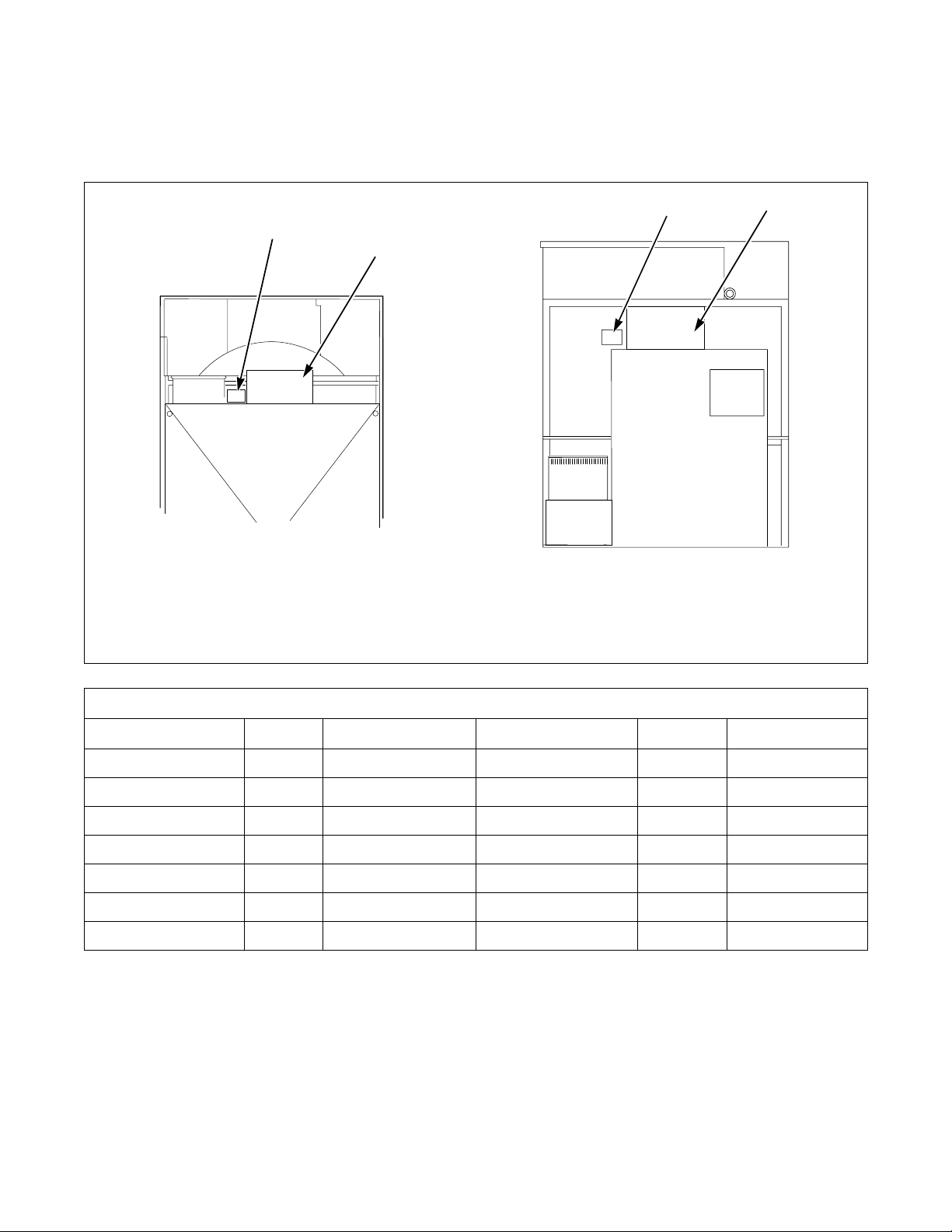
Serial Plate Location
When calling or writing for information about your
product, be sure to mention model and serial numbers.
1
2
Model and serial numbers are located on the serial
plate as shown.
1
2
120 POUND TUMBLER
1 Serial Plate
2 Junction Box Cover
170 POUND TUMBLER
Conversion Table
Multiply By To Obtain Multiply By To Obtain
Btu .252 kCal Pounds/sq. inch .06895 Bars
Btu 1055 Joules Pounds/sq. inch .070 kg/sq. cm
Inch 25.4 Millimeters Pounds (lbs.) .454 Kilograms
Inches W.C. .036 Pounds/sq. inch Boiler Horsepower 34,479 Btu/hr.
Inches W.C. .249 kPa Boiler Horsepower 34.5 lbs. Steam/hr.
2
lbf/inch
ft
(psi) .0369 kPa CFM .471 Liters/second
3
28.32 Liters kW 3414 Btu/hr.
T458I
6
© Copyright, Alliance Laundry Systems LLC – DO NOT COPY or TRANSMIT
M414038
Page 9
Safety Information
DANGER indicates the presence of a
hazard that will cause severe personal
injury, death, or substantial property
damage if the danger is ignored.
DANGER
WARNING indicates the presence of a
hazard that can cause severe personal
injury, death, or substantial property
damage if the warning is ignored.
WARNING
CAUTION indicates the presence of a
hazard that will or can cause minor
personal injury or property damage if the
caution is ignored.
CAUTION
Precautionary statements (“DANGER,”
“WARNING,” and “CAUTION”), followed by
specific instructions, are found in this manual and on
machine decals. These precautions are intended for the
personal safety of the operator, user, servicer, and
those maintaining the machine.
IMPORTANT: The word “IMPORTANT” is used
to inform the reader of specific procedures where
minor machine damage will occur if the procedure
is not followed.
NOTE: The word “NOTE” is used to communicate
installation, operation, maintenance or servicing
information that is important but not hazard
related.
WARNING
Failure to install, maintain, and/or operate
this machine according to manufacturer’s
instructions may result in conditions which
can produce serious injury, death and/or
property damage.
W051
NOTE: The WARNINGS and IMPORTANT
instructions appearing in this manual are not
meant to cover all possible conditions and
situations that may occur. It must be understood
that common sense, caution and carefulness are
factors which CANNOT be built into this tumbler.
These factors MUST BE supplied by the person(s)
installing, maintaining or operating the tumbler.
Additional precautionary statements (“IMPORTANT”
and “NOTE”) are followed by specific instructions.
Always contact your dealer, distributor, service agent
or the manufacturer on any problems or conditions you
do not understand.
M414038
© Copyright, Alliance Laundry Systems LLC – DO NOT COPY or TRANSMIT
7
Page 10
Safety Information
To reduce the risk of fire, electric shock,
serious injury or death to persons when
using your tumbler, read and follow these
basic precautions:
W359
WARNING
Save These Instructions
Important Safety Instructions
1. Read all instructions before using the tumbler.
2. Refer to the Grounding Instructions for the
proper grounding of the tumbler.
3. Do not dry articles that have been previously
cleaned in, washed in, soaked in, or spotted with
gasoline, dry cleaning solvents, other flammable
or explosive substances as they give off vapors
that could ignite or explode.
4. Do not allow children to play on or in the
tumbler. Close supervision of children is
necessary when the tumbler is used near children.
This is a safety rule for all appliances.
5. Before the tumbler is removed from service or
discarded, remove the door to the drying
compartment and the door to the lint
compartment.
6. Do not reach into the tumbler if the cylinder is
revolving.
7. Do not install or store the tumbler where it will
be exposed to water and/or weather.
8. Do not tamper with the controls.
9. Do not repair or replace any part of the tumbler,
or attempt any servicing unless specifically
recommended in the user-maintenance
instructions or in published user-repair
instructions that you understand and have the
skills to carry out.
10. Do not use fabric softeners or products to
eliminate static unless recommended by the
manufacturer of the fabric softener or product.
11. To reduce the risk of fire, DO NOT DRY plastics
or articles containing foam rubber or similarly
textured rubberlike materials.
12. Always clean the lint filter daily.
13. Keep area around the exhaust opening and
adjacent surrounding area free from the
accumulation of lint, dust and dirt.
14. The interior of the tumbler and the exhaust duct
should be cleaned periodically by qualified
service personnel.
15. If not installed, operated and maintained in
accordance with the manufacturer’s instructions
or if there is damage to or mishandling of this
product’s components, use of this product could
expose you to substances in the fuel or from fuel
combustion which can cause death or serious
illness and which are known to the State of
California to cause cancer, birth defects or other
reproductive harm.
16. Tumbler will not operate with the loading door
open. DO NOT bypass the door safety switch to
permit the tumbler to operate with the door open.
The cylinder will stop rotating when the door is
opened. Do not use the tumbler if the cylinder
does not stop rotating when the door is opened or
starts rotating without pressing or turning the
START mechanism. Remove the tumbler from
use and call for service.
17. Do not put articles soiled with vegetable or
cooking oil in the tumbler, as these oils may not
be removed during washing. Due to the
remaining oil, the fabric may catch on fire by
itself.
18. To reduce the risk of fire, DO NOT put clothes
which have traces of any flammable substances
such as machine oil, flammable chemicals,
thinner, etc. or anything containing wax or
chemicals such as in mops and cleaning cloths, or
anything dry-cleaned at home with dry-cleaning
solvent in the tumbler.
19. Use the tumbler only for its intended purpose,
drying fabrics.
20. ALWAYS disconnect the electrical power to the
tumbler before servicing. Disconnect power by
shutting off appropriate breaker or fuse.
8
© Copyright, Alliance Laundry Systems LLC – DO NOT COPY or TRANSMIT
M414038
Page 11
Safety Information
21. Install this tumbler according to this Installation
Manual. All connections for electrical power,
grounding and gas supply must comply with
local codes and be made by licensed personnel
when required.
22. Remove laundry immediately after tumbler
stops.
23. Always read and follow manufacturer’s
instructions on packages of laundry and cleaning
aids. Heed all warnings or precautions. To reduce
the risk of poisoning or chemical burns, keep
them out of reach of children at all times
(preferably in a locked cabinet).
24. Do not tumble fiberglass curtains and draperies
unless the label says it can be done. If they are
dried, wipe out the cylinder with a damp cloth to
remove particles of fiberglass.
25. Always follow the fabric care instructions
supplied by the garment manufacturer.
26. Never operate the tumbler with any guards and/or
panels removed.
27. DO NOT operate the tumbler with missing or
broken parts.
28. DO NOT bypass any safety devices.
29. Failure to install, maintain, and/or operate this
machine according to the manufacturer’s
instructions may result in conditions which can
produce bodily injury and/or property damage.
30. Solvent vapors from dry-cleaning machines
create acids when drawn through the heater of the
unit. These acids are corrosive to the tumbler as
well as to the laundry load being dried. Be sure
make-up air is free of solvent vapors.
WARNING
To reduce the risk of serious injury, install
lockable door(s) to prevent public access
to rear of tumblers.
W055
M414038
© Copyright, Alliance Laundry Systems LLC – DO NOT COPY or TRANSMIT
9
Page 12

Notes
10
© Copyright, Alliance Laundry Systems LLC – DO NOT COPY or TRANSMIT
M414038
Page 13
Specifications and Dimensions
Specifications 120 Pound 170 Pound
Cylinder Size 44 in. x 41 in. (1118 mm x 1041 mm) 50.75 in. x 42.5 in. (1289 mm x 1080 mm)
Cylinder Capacity Dry Weight 120 lbs. (54.4 kg) 170 lbs. (77.1 kg)
Cylinder Motor Horsepower 3/4 3/4
Fan Motor Horsepower 1 3
Air Outlet Diameter 10 in. (254 mm) 12 in. (300 mm)
Maximum Static Back Pressure 0.3 W.C.I. (0.8 mbar) 0.3 W.C.I. (0.8 mbar)
Maximum Airflow 1600 C.F.M. (755 L/sec) 2450 C.F.M. (1156 L/sec)
Gas Models
Net Weight 1275 lbs. (580 kg) 1575 lbs. (716 kg)
Gas Connection 3/4 in.
Gas Consumption 300,000 Btu/hr (316 Mj/hr) 395,000 Btu/hr (421 Mj/hr)
Net Weight 1375 lbs. (625 kg) 1675 lbs. (761 kg)
Steam Connection 3/4 in.
Steam Consumption 10 bhp (335,000 Btu) 15 bhp (502,500 Btu)
NPT 1 in. NPT
Steam Models
NPT 3/4 in. NPT inlet
1 in. NPT outlet
M414038
© Copyright, Alliance Laundry Systems LLC – DO NOT COPY or TRANSMIT
11
Page 14
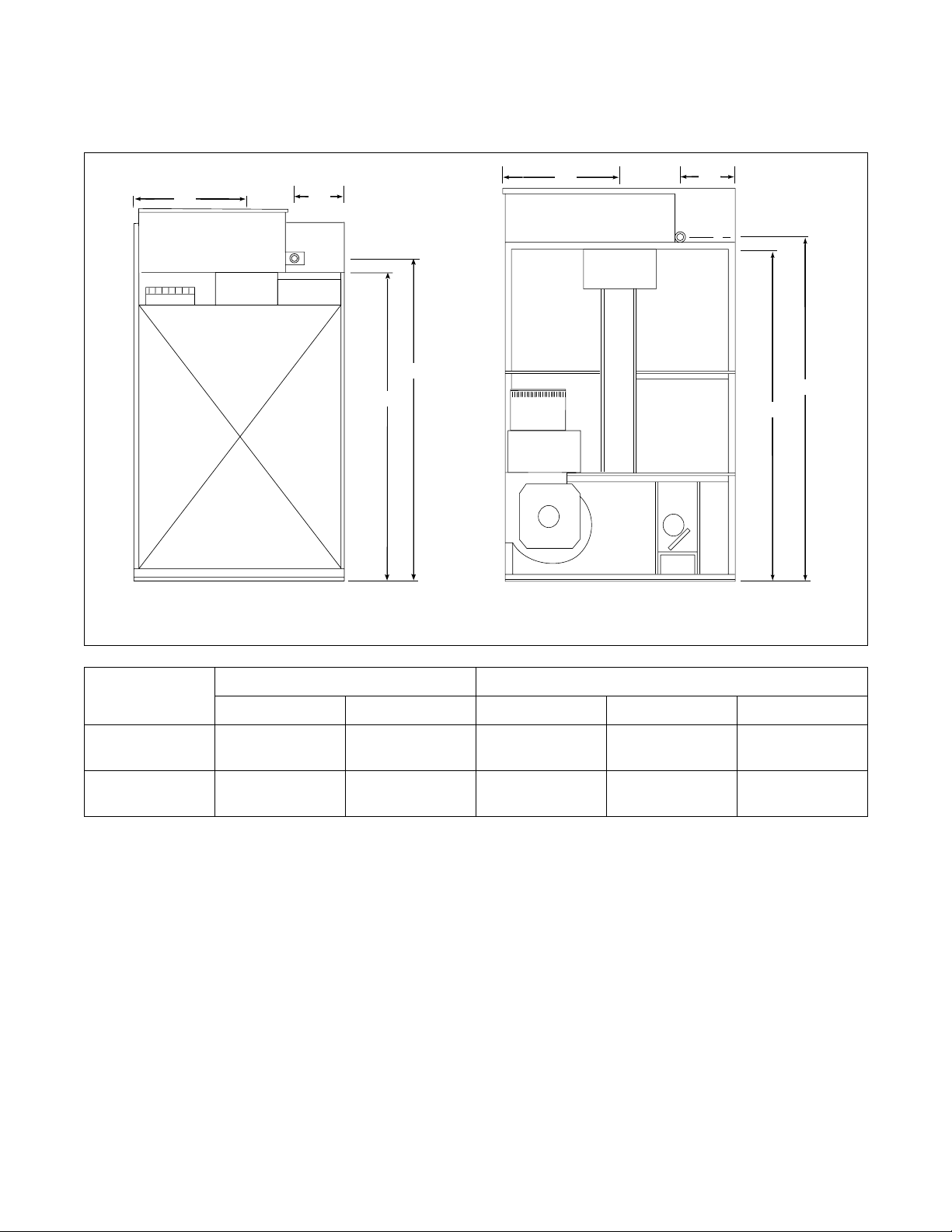
Specifications and Dimensions
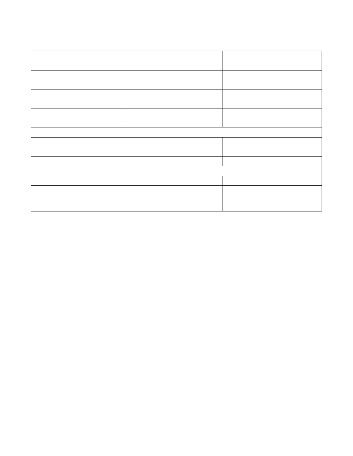
120 Pound Tumbler Dimensions and
Exhaust Outlet Locations
V
TOP VIEW
OF EXHAUST
DUCT
W
X
X
U
B
A
Y
C
D
Z
E
F
T365i
T365I
Cabinet Dimensions
ModelsABCDEF
120FG 31.3125 in.
(795 mm)
120CSH 31.3125 in.
(795 mm)
30.5 in.
(775 mm)
30.5 in.
(775 mm)
48.625 in.
(1235 mm)
48.625 in.
(1235 mm)
65 in.
(1235 mm)
65 in.
(1235 mm)
46.5 in.
(1181 mm)
46.5 in.
(1181 mm)
85.5 in.
(2172 mm)
83.5 in.
(2121 mm)
Refer to Position and Level the Tumbler to temporarily reduce the heights of these models.
Exhaust Outlet Dimensions and Locations
Models U V W X Y Z
120FG 63.5 in.
120CSH 60.75 in.
12
(1613 mm)
(1543 mm)
© Copyright, Alliance Laundry Systems LLC – DO NOT COPY or TRANSMIT
8.5 in.
(216 mm)
8.5 in.
(216 mm)
7.5 in.
(190 mm)
7.5 in.
(190 mm)
8 in.
(203 mm)
8 in.
(203 mm)
8.75 in.
(222 mm)
8.75 in.
(222 mm)
8.125 in.
(206 mm)
8.125 in.
(206 mm)
M414038
Page 15
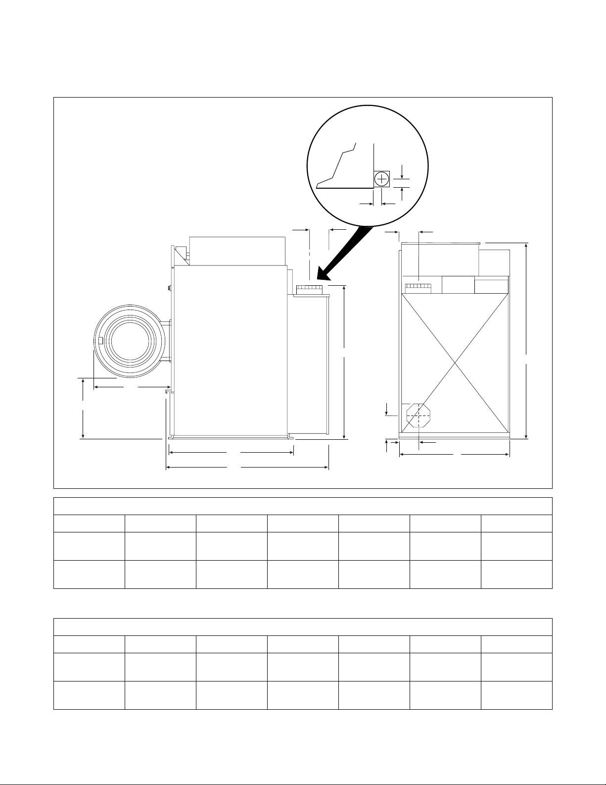
170 Pound Tumbler Dimensions and
Exhaust Outlet Locations
OF EXHAUST
Specifications and Dimensions
TOP VIEW
DUCT
Y
X
Y
W
B
V
A
C
D
E
F
T364I
Cabinet Dimensions
ModelsABCDEF
170FG/CSH 31.3125 in.
(795 mm)
30.5 in.
(775 mm)
51.75 in.
(1314 mm)
66.125 in.
(1680 mm)
53.125 in.
(1349 mm)
94 in.
(2388 mm)
Refer to Position and Level the Tumbler to temporarily reduce the heights of these models.
Exhaust Outlet Dimensions and Locations
Models V W X Y
170FG/CSH 42.375 in.
M414038
6.75 in.
(1076 mm)
© Copyright, Alliance Laundry Systems LLC – DO NOT COPY or TRANSMIT
(171 mm)
7 in.
(178 mm)
8.75 in.
(222 mm)
13
Page 16
Specifications and Dimensions
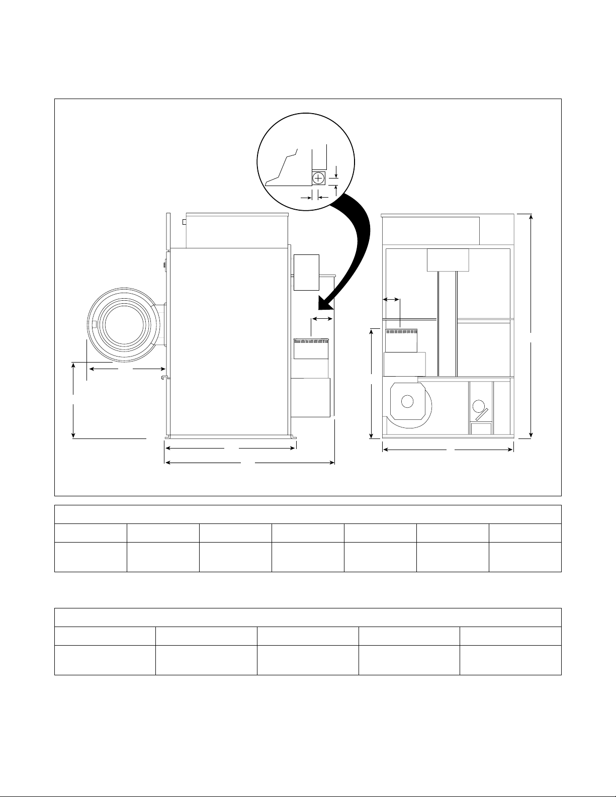
Electric and Gas Connection
Locations for FG Models
A
A
120FG
C
D
B
170FG
C
D
B
T362i
T362I
Models
Electrical Connection Gas Connection
ABCDDiameter
120FG 24 in.
(610 mm)
170FG 27 in.
(686 mm)
70.125 in.
(1781 mm)
75 in.
(1905 mm)
13 in.
(330 mm)
14.5 in.
(368 mm)
70.25 in.
(1784 mm)
77.375 in.
(1965 mm)
0.75 in. (19 mm)
NPT
1 in. (25 mm)
NPT
14
© Copyright, Alliance Laundry Systems LLC – DO NOT COPY or TRANSMIT
M414038
Page 17
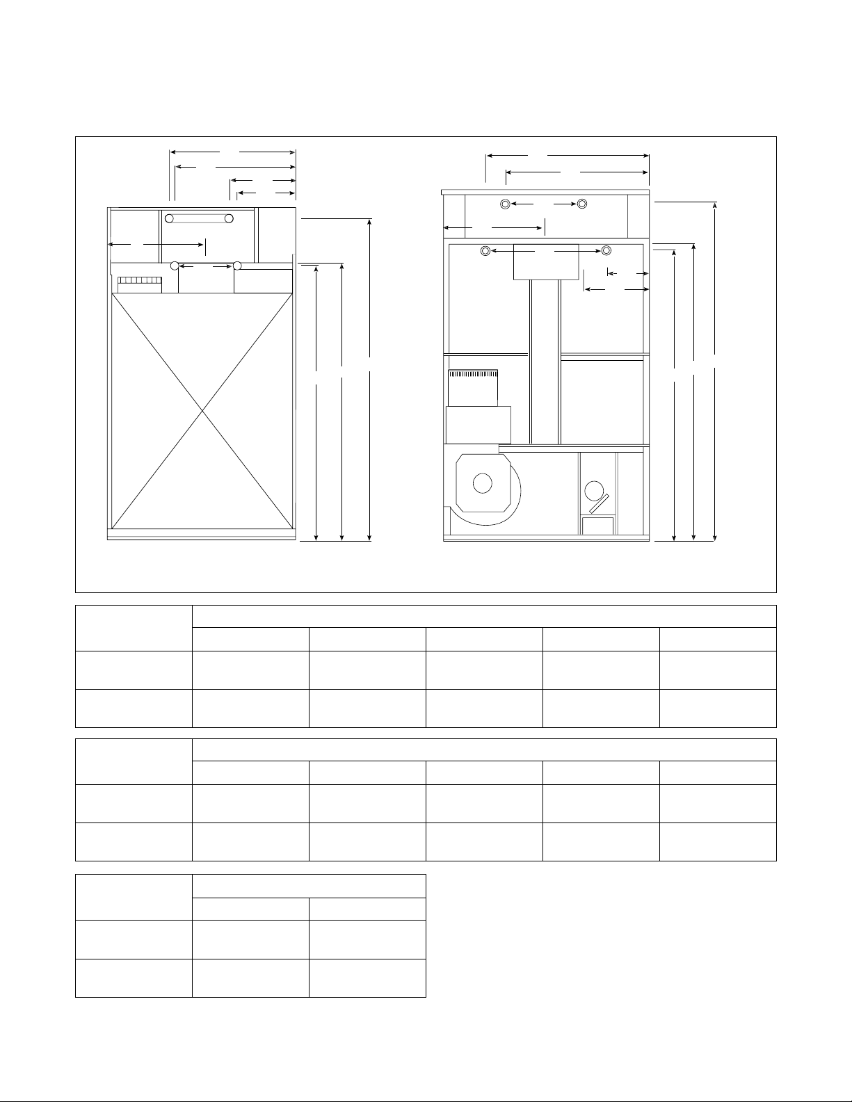
Electric and Steam Connection
Locations for CSH Models
Specifications and Dimensions
A1
B1
C
D2
120CSH
A2
B2
C
G
F
E
B1
D1
D2
170CSH
A1
A2
B2
G
F
E
T363i
T363I
Models
Diameter A1 A2 G D1
120CSH 0.75 in. (19 mm)
NPT
170CSH 0.75 in. (19 mm)
NPT
Models
Diameter B1 B2 E D2
120CSH 1 in. (25 mm)
NPT
170CSH 1 in. (25 mm)
NPT
Electrical Connection
Models
CF
120CSH 24 in.
(610 mm)
170CSH 27 in.
(686 mm)
35.875 in.
(911 mm)
37.625 in.
(956 mm)
34.625 in.
(879 mm)
44.625 in.
(1133 mm)
68.75 in.
(1726 mm)
75 in.
(1905 mm)
Steam Inlet
13.375 in.
(340 mm)
15.25 in.
(387 mm)
Steam Outlet
13.125 in.
(333 mm)
8.75 in.
(222 mm)
82.75 in.
(2102 mm)
88 in.
(2235 mm)
68.5 in.
(1740 mm)
71.75 in.
(1822 mm)
N/A
21.625 in.
(549 mm)
21.5 in.
(546 mm)
35.625 in.
(905 mm)
M414038
© Copyright, Alliance Laundry Systems LLC – DO NOT COPY or TRANSMIT
15
Page 18

Notes
16
© Copyright, Alliance Laundry Systems LLC – DO NOT COPY or TRANSMIT
M414038
Page 19

Installation
IMPORTANT: Warranty is void unless tumbler is
installed according to instructions in this manual.
Installation should comply with minimum
specifications and requirements detailed in this
manual and applicable local gas fitting regulations,
municipal building codes, water supply regulations,
electrical wiring regulations, and any other
relevant statutory regulations. Due to varied
requirements, applicable local codes should be
thoroughly understood and all pre-installation
work arranged for accordingly.
Pre-Installation Inspection
Upon delivery, visually inspect the packaging and
portions of the product visible through the packaging
for shipping damage. If the package or product is
damaged or if signs of possible damage are evident,
have the carrier note the condition on the shipping
papers before the shipping receipt is signed, or advise
the carrier of the condition as soon as it is discovered.
Remove the crate and protective cover as soon as
possible and check the items listed on the packing list.
Advise the carrier of any damaged or missing articles
as soon as possible. A written claim should be filed
with the carrier immediately if articles are damaged
or missing.
Materials Required (Obtain locally)
All Models
Gas Models
Steam Models
One fused disconnect switch or
circuit breaker.
One gas shut-off valve for gas
service line to each tumbler.
One steam shut-off valve for steam
service line to be connected
upstream of solenoid steam valve.
Two steam shut-off valves for each
condensate return line.
Flexible steam hoses with a 125 psig
(pounds per square inch gauge)
(8.79 kg/sq. cm) working pressure
for connecting steam coils. Refer to
Figure 16 and Figure 17 for sizing
and connection configurations.
Three steam traps for steam coil
outlet to condensate return line.
Three vacuum breakers for
condensate return lines.
IMPORTANT: Keep tumbler area clear and free
from combustible materials, gasoline and other
flammable vapors and liquids.
M414038
© Copyright, Alliance Laundry Systems LLC – DO NOT COPY or TRANSMIT
17
Page 20
Installation
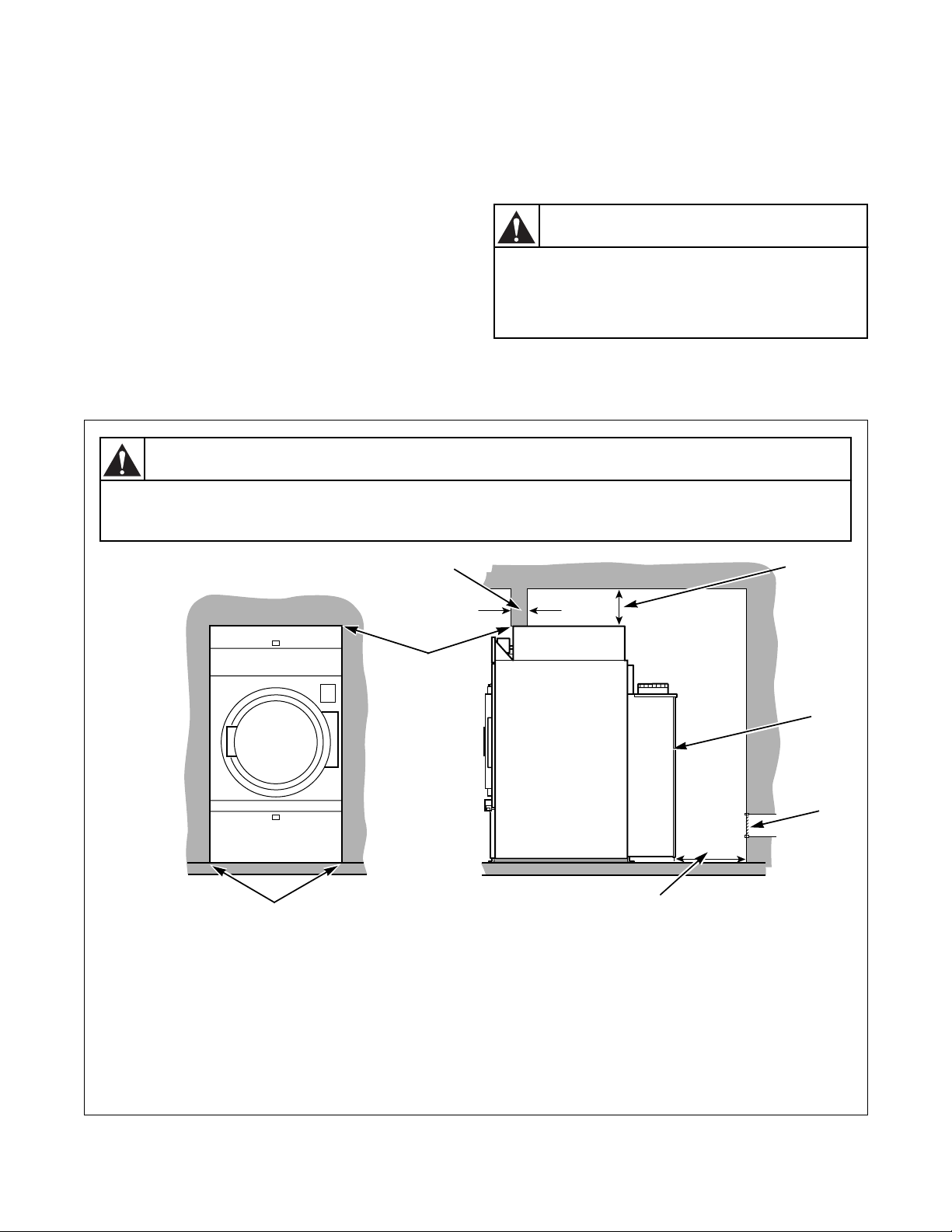
Location Requirements
A typical tumbler enclosure is shown in Figure 1. Note
that the enclosure touches the tumbler top and side
The tumbler must be installed on a level floor capable
of supporting 120 lbs./ft
2
(585.8 kg/m2). Floor
covering materials such as carpeting or tile should be
panels. Also, note the minimum and maximum
dimensions. Local codes and ordinances must be
complied with.
removed.
To assure compliance, consult local building code
requirements.
The tumbler MUST NOT be installed or stored in area
where it will be exposed to water and/or weather.
To reduce the risk of serious injury, install
lockable door(s) to prevent public access
WARNING
to rear of tumblers.
IMPORTANT: DO NOT block the airflow at the
rear of the tumbler with laundry or other articles.
Doing so would prevent adequate air supply to the
combustion chamber of the tumbler.
IMPORTANT: Install tumblers with sufficient
clearance for servicing and operation. Refer to
Figure 1.
WARNING
To reduce the risk of severe injury, clearance of tumbler cabinet from combustible
construction must conform to the minimum clearances.
W055
W056
2
1
7
NOTE: Shaded areas indicate adjacent structure.
1 Zero clearance permitted for first 4 in. (102 mm)
2 4 in. (102 mm)
3 Minimum clearance permitted for remainder: Gas 4 in. (102 mm), Steam 12 in. (305 mm)
4 Guard
5 Provision for Make-Up Air
6 24 in. (610 mm) Minimum, 36 in. (914 mm) recommended for maintenance purposes
7 Zero Clearance
3
4
5
6
TMB237N
18
Figure 1
© Copyright, Alliance Laundry Systems LLC – DO NOT COPY or TRANSMIT
M414038
Page 21

Installation
Position and Level the Tumbler
For further assistance, refer to the Section on Location
Requirements.
The tumbler may be moved with or without the skid.
To remove the skid, unscrew the four shipping bolts,
and discard them.
To fit a 170 pound tumbler (with shipping skid)
through an 8 foot high door, you must remove the front
access panel. The upper 3 inches of the stove must also
be removed on 170 pound gas tumblers. Removing the
entire gas or steam heater assembly and the shipping
skid, will reduce the height of the 120 pound tumbler
to 70 inches (1778 mm), and the 170 pound tumbler to
75 inches (1905 mm).
Level the tumbler to within 1/8 inch (3 mm) from
front-to-rear (level on cylinder rib), and side-to-side
(level on top panel). Shim under corners to level and
stabilize unit. Tumbler must not rock.
Before Placing Tumbler into Service
1. Remove or open all panels and check accessible
bolts, nuts, screws, terminals and fittings for
tightness.
2. Check V-belt tension and adjust if necessary.
Refer to appropriate paragraphs in Adjustments
Section.
3. Replace all panels and guards.
4. Turn on electrical supply to tumbler.
5. Open supply valve for gas or steam.
6. After performing the previous checks, start
the tumbler by pressing START (hold for
approximately 3 seconds). Release the start
button and open the loading door. The cylinder
should stop rotating within 7 seconds after the
door is opened a maximum of 2 inches
(50.8 mm) plus or minus 1/4 inch (6.35 mm). If it
does not, adjust the loading door interlock. Refer
to the appropriate paragraph in Adjustments
Section.
7. Gas tumblers: Start the tumbler and check the
burner flame. Adjust the gas inlet shutter as
required. Refer to the appropriate paragraph
in Adjustments Section.
IMPORTANT: The Electronic Ignition system will
attempt to light the gas by sparking for the “trial
for ignition” period. If gas does ignite within this
period, the ignition control will go into a safety
lockout and the valve will no longer open until the
control is reset. Refer to Table 1. It may be
necessary to restart several times to bleed air out of
gas lines. To reset, open and close loading door,
then start.
Location
Australia 18 5 Open loading
Europe 18 10 Press reset
All others
(MT/CD)
All other
(OM)
Prepurge
Time
(seconds)
1 15 Open loading
1-3 10 Open loading
Trial for
Ignition
(seconds)
Table 1
Reset
Lockout
Condition
By:
door
button on rear
of machine
door
door
If lockout condition persists, check that the manual
gas shut-off valve is in the open position and that
the gas service is properly connected. If condition
still persists, remove tumbler from service.
8. Load the cylinder with a full load of clothes or
clean rags and run to remove oil or dirt from
cylinder.
M414038
© Copyright, Alliance Laundry Systems LLC – DO NOT COPY or TRANSMIT
19
Page 22

Installation
The tumbler must not be operated if the
airflow switch does not operate properly.
Faulty airflow switch operation may cause
an explosive gas mixture to collect in the
tumbler.
W072
WARNING
Required for CE Marked Models
Once machine is installed, please be sure to complete
the following items:
● Review and verify machine operation with
customer.
● Leave Operating Instructions and a signed
Declaration of Conformity with customer.
9. Check the airflow switch operation by opening
the lint panel; be sure to remove shipping tape
from airflow switch prior to operation. Refer to
Figure 21 and Figure 22. The heating systems
should shut off when the lint panel is opened a
maximum of 6 inches (152.4 mm). The airflow
switch operation may be affected by lack of
make-up air or an obstruction in the exhaust duct.
These should be checked; if there is a problem
contact an authorized service person.
10. Wipe out the cylinder using an all-purpose
cleaner or detergent and water solution.
If tumbler does not meet any of the above
requirements, remove tumbler from service. Refer to
Removing Tumbler from Service Section.
● Review machine warranty information with
customer.
● Apply warning sticker on front panel of machine,
in language appropriate to country of sale (found
in literature packet).
20
© Copyright, Alliance Laundry Systems LLC – DO NOT COPY or TRANSMIT
M414038
Page 23
Installation
WARNING
To reduce the risk of electric shock, fire,
explosion, serious injury or death:
• Disconnect electric power to the
tumbler before servicing.
• Close gas shut-off valve to gas tumbler
before servicing.
• Close steam valve to steam tumbler
before servicing.
• Never start the tumbler with any guards/
panels removed.
• Whenever ground wires are removed
during servicing, these ground wires
must be reconnected to ensure that the
tumbler is properly grounded.
W002
Installing Gas Drying Tumblers in
the European Union (EU)
General Information
This information is to be used when installing gas
tumblers in countries, and/or on gases, different than
the machine’s factory configuration. Tumblers are
supplied from the factory for operation on Natural Gas
or L.P. Gas in the countries of GB/IE/PT/ES/IT. To
install machines in any other country or on any other
gas requires some level of modification.
Orifices, stickers, block-open kits, regulator springs
and other parts needed for gas conversions are to be
ordered separately.
Models are built in three different configurations:
● Regulated Natural Gas – Injector is sized for
Natural Gas, second family, group H (E) at
20 mbar inlet pressure. Regulator/governor is
operational. Gas valve CAN be field converted to
a non-regulating type.
● Unregulated Natural Gas – Injector is sized for
Natural Gas, second family, group E+ at
20.25 mbar inlet pressure. Regulator/governor is
blocked open. Gas valve CANNOT be fieldconverted to a regulating type.
● Unregulated L.P. (Liquified Petroleum) Gas –
Injector is sized for L.P. Gas, third family, group
3+ at 28.37 mbar inlet pressure. Regulator/
governor is blocked open. Gas valve CANNOT
be field-converted to a regulating type.
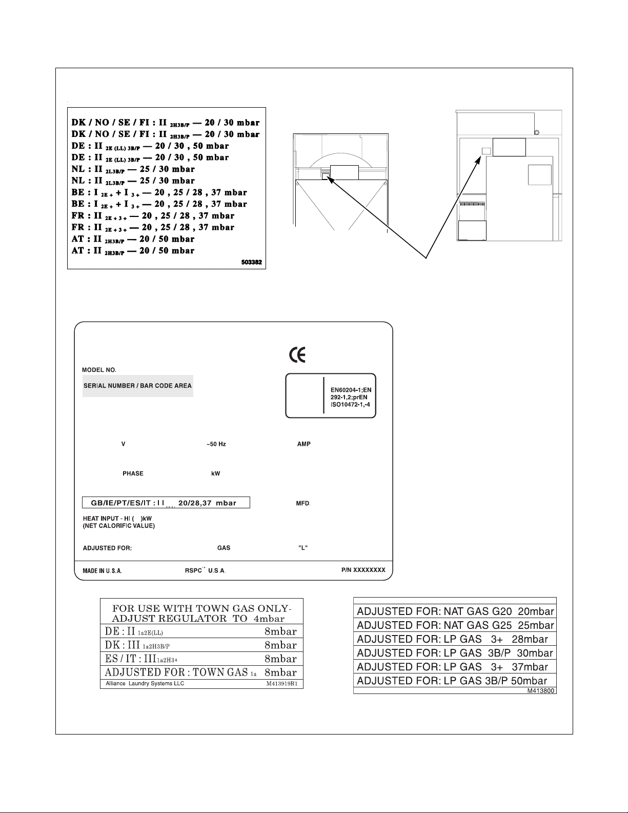
Serial plates supplied from the factory are configured
for the countries of GB/IE/PT/ES/IT. These
instructions pertain to the situations when the country
of use or gas supply is different than that on the serial
plate.
The tables describe the different gases that are
available in different EU countries, and how the
machines need to be configured to operate with those
gases. In the EU, there are Natural Gas configurations
that do not allow for machine regulation, and L.P. Gas
configurations that must be regulated. For L.P. Gas,
third family B/P at 50 mbar, order Regulated Natural
Gas machines and convert according to Table 2 or
Table 3.
M414038
© Copyright, Alliance Laundry Systems LLC – DO NOT COPY or TRANSMIT
21
Page 24
Installation
WARNING
When converting the tumbler to a
different gas or pressure, first verify that
the supply inlet pressure is equipped with
a pressure regulator (located ahead of the
tumbler) that will maintain the gas supply
at the inlet pressure specified.
W430
Basic Configuration
1. Determine the necessary conversion operations
to convert from the factory-supplied
configuration to the desired configuration.
2. Perform the conversions required so the machine
is properly configured for the desired country and
gas (refer to Specific Conversion Procedures
Section):
● How to Convert Gas Valve from Regulated to
Unregulated
NOTE: Conversion from regulated to unregulated
is only needed when regulated tumblers were
ordered, but unregulated tumblers were needed.
● How to Change Injector (Orifice) Size
● How to Adjust Gas Valve Governor/Regulator
3. If applicable, peel off the appropriate country
sticker from Part No. 503382 (included with
machine) and apply it to the serial plate over the
existing country information. Refer to Figure 7.
4. If applicable, peel off the appropriate conversion
sticker from Part No. M413800 (included with
machine) and apply it to the serial plate over the
“ADJUSTED FOR ______ GAS: ______”
information. Refer to Figure 7.
SPECIFIED
LOCAL INLET
PRESSURE
2
3
1
1 Gas Shut-Off Valve (Ahead of pressure tap)
2 Pressure Tap
3 Gas Shut-Off Valve (Shown in closed
position)
Figure 2
T103K
22
© Copyright, Alliance Laundry Systems LLC – DO NOT COPY or TRANSMIT
M414038
Page 25
Installation
Specific Conversion Procedures
How to Convert Gas Valve from Regulated to
Unregulated
NOTE: Conversion from regulated to unregulated
is only needed when regulated tumblers were
ordered, but unregulated tumblers were needed.
1. B-M gas valve:
(120 Pound Models)
Refer to Ta b le 2 .
a. Disconnect electrical power from tumbler.
Close gas shut-off valve to tumbler. Refer to
Figure 2.
b. Remove converter cover screw. Invert brass
converter and install with breather hole down.
Reinstall converter cover screw. Refer to
Figure 4.
c. Change injector size as required by the
appropriate table according to How to
Change Injector (Orifice) Size.
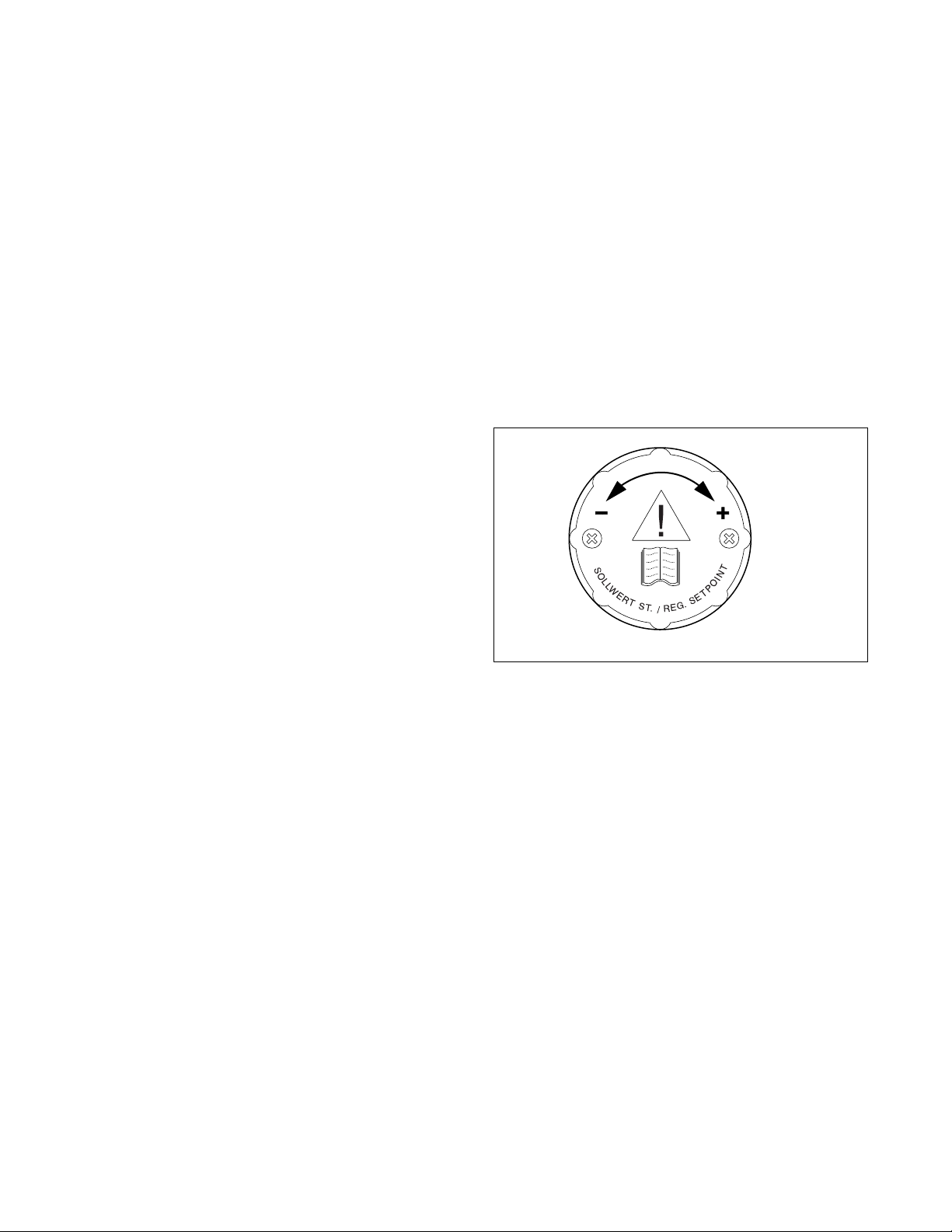
2. Johnson GM2000 gas valve:
(170 Pound Models)
Refer to Ta b le 3 .
a. Disconnect electrical power from tumbler.
Close gas shut-off valve to tumbler. Refer to
Figure 2.
b. Loosen screws on regulator adjustment knob,
then turn knob clockwise. When knob no
longer turns, retighten screws. Refer to
Figure 3.
c. Change injector size as required by the
appropriate table according to How to
Change Injector (Orifice) Size.
d. Commission tumbler for use.
d. Commission tumbler for use.
TMB1272N
Figure 3
M414038
© Copyright, Alliance Laundry Systems LLC – DO NOT COPY or TRANSMIT
23
Page 26
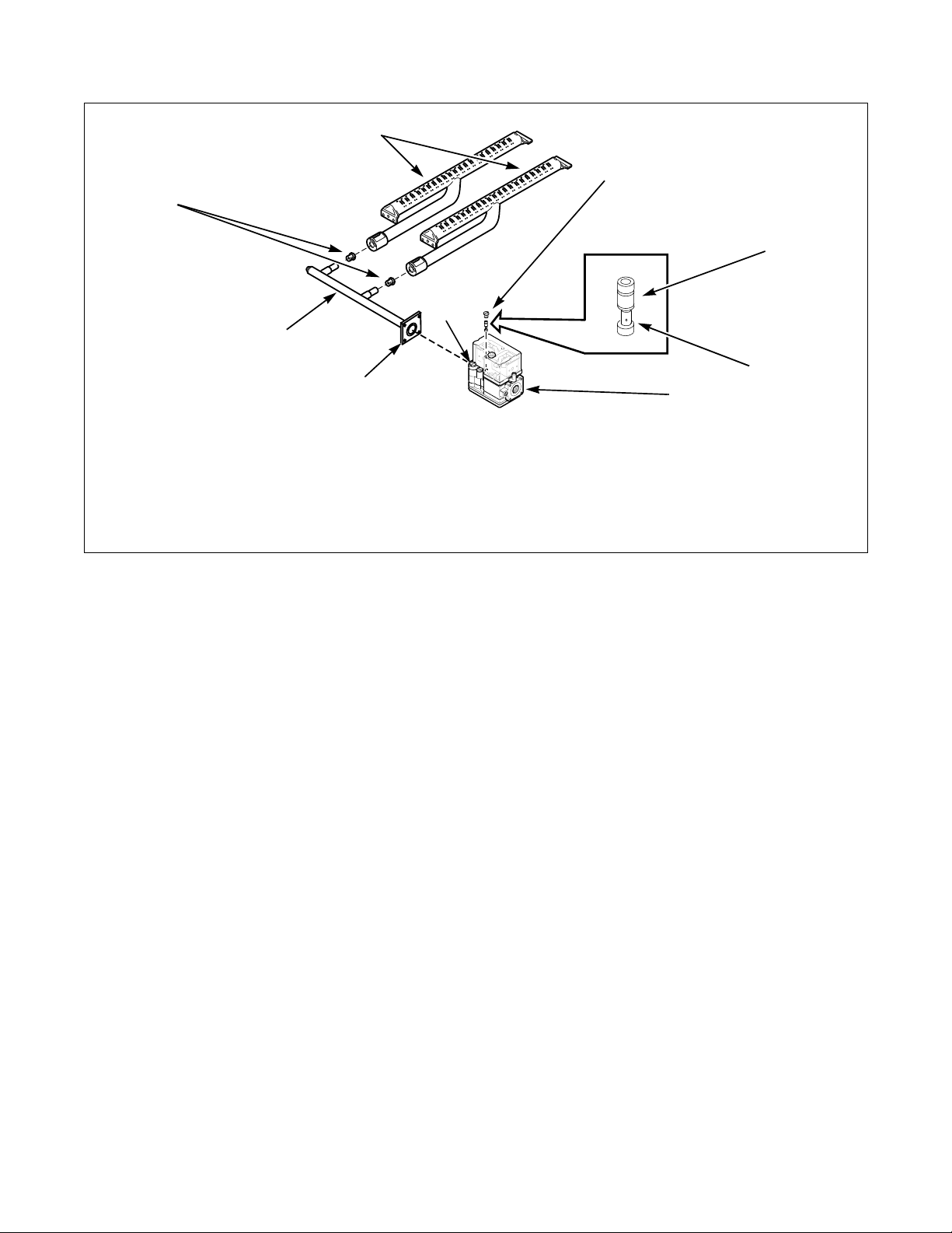
Installation
1
2
8
5
7
6
UNREGULATED (REGULATOR BLOCKED OPEN)
1 Burner 5 Regulator Cap
2 Converter Cover Screw 6 Gas Valve Flange Gasket
3 Brass Converter 7 Spud Holder
4 Gas Valve 8 Burner Orifice Spud
T107K
3
BREATHER
4
HOLE DOWN
T107K
How to Change Injector (Orifice) Size
1. Disconnect electrical power from tumbler. Close
gas shut-off valve to tumbler. Refer to Figure 2.
2. Remove gas valve:
a. B-M Gas Valve (120 Pound Models) – Use a
4 mm Allen wrench to remove the four screws
holding the spud holder flange to the gas
valve. Remove the burner orifice(s) from the
spud holder. Refer to Figure 4.
b. Johnson GM2000 Gas Valve (170 Pound
Models) – Use a 5 mm Allen wrench to
remove the four screws holding the spud
holder flange to the gas valve. Remove the
burner orifice(s) from the spud holder. Refer
to Figure 4. When converting from Natural
Gas to L.P. Gas, the left-most burner and
injector (viewed from front) must be removed.
In place of the removed injector, a blank
injector (Part No. M400995) and a Burner
Opening Cover (Part No. M413099) must be
installed.
Figure 4
3. Install the new, correct injector(s) (orifices).
Refer to Figure 6. Torque each to 9-10 Nm.
4. Reinstall spud holder assembly to gas valve,
making certain orifice(s) are in line with burner
tube opeing, and flange gasket is in place in
flange grove. Refer to Figure 4 or Figure 5.
5. Commission tumbler for use.
NOTE: Blank injectors (orifices) are available as
Part No. M400995.
24
© Copyright, Alliance Laundry Systems LLC – DO NOT COPY or TRANSMIT
M414038
Page 27
Installation
1
REQUIRED
INJECTOR
PRESSURE
9
8
1 Burner Tube Attaching Screws 6 Spud Holder Nut
2 Burner Support Bracket 7 Spud Holder
3 Pressure Tap 8 Pressure Tap (Alternate location)
4 Gas Valve 9 Manometer
5 Gas Valve Flange
7
2
6
5
3
4
T137K
How to Adjust Gas Valve Governor/Regulator
1. Check gas injector (manifold) pressure as
follows. Refer to Figure 5.
2. Remove screw plug from inside pressure tap.
3. Connect a “U”-tube manometer (or similar
pressure gauge) to the injector (manifold)
pressure tap.
4. Start tumbler and note pressure once flame is
burning. Remove regulator cap and adjust
regulator screw until the injector pressure per
applicable table is achieved. Replace regulator
cap.
Figure 5
1
BURNER INJECTOR
(ORIFICE)
1 Size Stamped on Orifice
T025K
Figure 6
T025KE1D
M414038
© Copyright, Alliance Laundry Systems LLC – DO NOT COPY or TRANSMIT
25
Page 28

Installation
Model 120FG INPUT: 87.8 kW
Gas
GB IE PT ES IT DK NO SE FI DE NL BE FR AT
Type
1111122222 2
Nat.
Gas
555555
L.P.
Gas
77777 88
66
NOTE: In addition to directions below, follow all
instructions including verification and adjustment
of injector pressure.
1 – Order as Regulated Natural Gas. No modification
needed.
2 – Order as Regulated Natural Gas. Apply
appropriate country sticker.
3 – Order as Regulated Natural Gas. Apply
appropriate country and gas stickers.
4 – Order as Unregulated with Unregulated Natural
Gas injectors. Apply appropriate country sticker.
3
44
Gas
Family
& Group
2nd
family
Group H
(E)
2nd
family
Group L
(LL)
2nd
family
Group E+
3rd
family
Group
B/P
3rd
family
Group
B/P
3rd
family
Group 3+
Inject. 0
4.8 mm
4.8 mm
4.2 mm
2.6 mm
2.6 mm
2.6 mm
Inject. Qty
& Part. No.
3
M411372
3
M411372
3
M402295
3
M411376
3
M411376
3
M411376
Inlet
Press.
20 mbar Yes 8.9 mbar
25 mbar Yes
20.25
mbar
30 mbar No Unreg.
50 mbar Yes
28.37
mbar
Table 2
6 – Order as Regulated Natural Gas. Convert with
(3) 2.6 mm injectors Part No. M411376. Apply
appropriate country and gas stickers.
7 – Order as Unregulated with L.P. Gas injectors. No
modification needed.
8 – Order as Unregulated with L.P. Gas injectors.
Apply appropriate country sticker.
OPEN – No Approval available.
Special Cases – No additional kits are required to
convert from regulated to unregulated.
Gvnr./
Regltr.
No Unreg.
No Unreg.
Inject.
Press.
12.0
mbar
26.4
mbar
5 – Order as Unregulated with L.P. Gas injectors.
Apply appropriate country sticker.
26
© Copyright, Alliance Laundry Systems LLC – DO NOT COPY or TRANSMIT
M414038
Page 29

Installation
Model 170FG Input: 115.8 kW Flue Code: B
Gas
GB IE PT ES IT DK NO SE FI DE NL BE FR AT
Type
1111122222 2
Nat.
Gas
555555
L.P.
Gas
77777 88
66
NOTE: In addition to directions below, follow all
instructions including verification and adjustment
of injector pressure.
3
44
Table 3
6 – Order as Regulated Natural Gas. Convert with
(3) 3.4 mm injectors Part No. M400997. Apply
appropriate country and gas stickers.
Gas
Family
& Group
2nd
family
Group H
(E)
2nd
family
Group L
(LL)
2nd
family
Group E+
3rd
family
Group
B/P
3rd
family
Group
B/P
3rd
family
Group 3+
Inject. 0
4.8 mm
4.8 mm
3.8 mm
3.4 mm
3.4 mm
3.4 mm
Inject. Qty
& Part. No.
4
M411372
4
M411372
4
M402997
3
M400997
3
M400997
3
M400997
Inlet
20.25
mbar
28.37
mbar
Gvnr./
Regltr.
No Unreg.
No Unreg.
Press.
20 mbar Yes 8.0 mbar
25 mbar Yes
30 mbar No Unreg.
50 mbar Yes
22
Inject.
Press.
12.0
mbar
28.7
mbar
1 – Order as Regulated Natural Gas. No modification
needed.
2 – Order as Regulated Natural Gas. Apply
appropriate country sticker.
3 – Order as Regulated Natural Gas. Apply
appropriate country and gas stickers.
4 – Order as Unregulated with Unregulated Natural
Gas injectors. Apply appropriate country sticker.
5 – Order as Unregulated with L.P. Gas injectors.
Apply appropriate country sticker.
7 – Order as Unregulated with L.P. Gas. No
modification needed.
8 – Order as Unregulated with L.P. Gas. Apply
appropriate country sticker.
OPEN – No Approval available.
Special Cases – When converting from Natural Gas to
L.P. Gas, the left-most burner and injector (viewed
from front) must be removed. In the place of the
removed injector, a blank injector Part Number
M400995 and a Burner Opening Cover Part Number
M413099 must be installed. No additional kits are
required to convert from regulated to unregulated.
M414038
© Copyright, Alliance Laundry Systems LLC – DO NOT COPY or TRANSMIT
27
Page 30
Installation
T458I
LOCATED
HERE
28
44001907
APPLICATION OF STICKERS TO SERIAL PLATE
Figure 7
© Copyright, Alliance Laundry Systems LLC – DO NOT COPY or TRANSMIT
M414038
Page 31

Exhaust Requirements
A drying tumbler produces combustible
lint. To reduce the risk of fire, the tumbler
must be exhausted to the outdoors.
W057
To reduce the risk of fire and accumulation
of combustible gases, DO NOT exhaust
tumbler air into a window well, gas vent,
chimney or enclosed, unventilated area
such as an attic wall, ceiling, crawl space
under a building, or concealed space of a
building.
W059
WARNING
Layout
Wherever possible, install tumblers along an outside
wall, where duct length can be kept to a minimum and
makeup air can be easily accessed. Construction must
not block the airflow at the top rear of the tumbler.
Doing so would prevent adequate air supply to the
tumbler combustion chamber.
Example: A tumbler with a rated input of
120,000 Btu/hour requires 120 square inches of free
opening.
The additional opening recommended by the
manufacturer is required for optimum drying
and reliability.
Louvers in opening to outdoors will reduce airflow.
Opening must compensate for area taken up by
louvers.
Make-up air openings in rooms containing tumbler(s)
and/or gas fired hot water heater or other gravity
vented appliances must be increased sufficiently to
prevent downdrafts in any of the vents when all
tumblers are in between tumbler(s) and make-up air
openings. If it is necessary to duct make-up air to
tumbler(s), increase area of duct work by 25% to
compensate for any restriction in air movement.
Venting
For maximum efficiency and minimum lint
accumulation, tumbler must be exhausted to the
outdoors by the shortest possible route.
Make-Up Air
A tumbler is forced air exhausted and requires
provisions for make-up air to replace air exhausted
by tumbler. Refer to Table 4.
IMPORTANT: Do not obstruct flow of combustion
and ventilation air.
Required Make-Up Air Opening
(to the outside) for Each Tumbler
Models Opening
120 Pound 360 in
170 Pound 575 in
Table 4
At a minimum, the National Fuel Gas Code
requires tumblers to have at least 1 square inch
(6.5 square cm) of opening for every 1000 Btu/hour
of input rating for proper combustion.
M414038
© Copyright, Alliance Laundry Systems LLC – DO NOT COPY or TRANSMIT
2
free air
2
free air
Proper sized exhaust ducts are essential for proper
operation. All elbows should be sweep type. Exhaust
ducts must be assembled so the interior surfaces are
smooth, so the joints do not permit the accumulation
of lint. Do not use sheet metal screws to joint vent
sections.
(2323 cm2)
(3710 cm2)
29
Page 32
Exhaust Requirements
Improperly sized or assembled ductwork
causes excess back pressure which
results in slow drying, lint collecting in the
duct, lint blowing back into the room, and
increased fire hazard.
W355
WARNING
Exhaust ducts shall be constructed of sheet metal
or other noncombustible material. Such ducts must
be equivalent in strength and corrosion resistance
to ducts made of galvanized sheet steel not less than
0.0195 inch (0.495 mm) thick.
Where the exhaust duct pierces a combustible wall
or ceiling, provide an opening with a diameter 4 inches
(102 mm) larger than the diameter of the exhaust duct.
Center duct in the opening. When ducts pass through
walls, ceilings, floors or partitions, the space around
the duct shall be sealed with noncombustible material.
Refer to Figure 12.
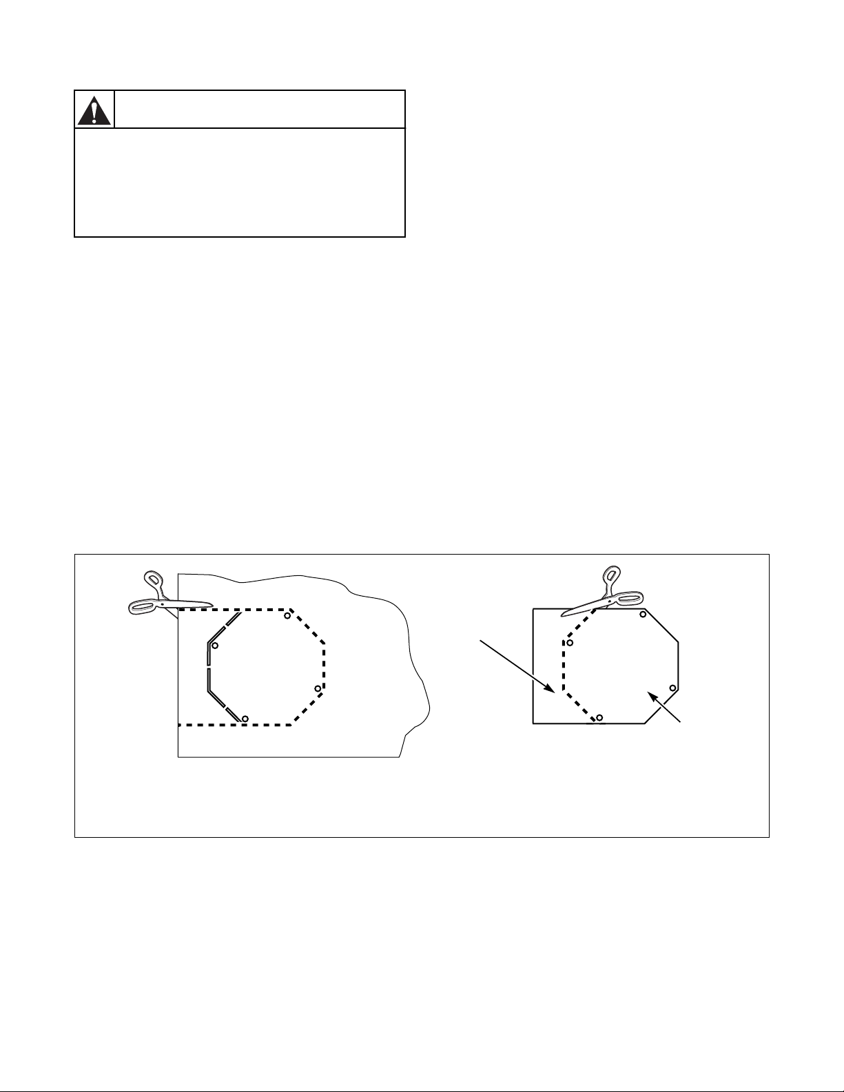
Alternate Venting for 120 Pound Tumblers
The 120 pound tumbler is equipped from the factory
to exhaust from the top; however, it may be converted
to exhaust out the rear by doing the following (refer to
Specifications and Dimensions):
1. Remove belt guard cover.
2. Remove 10 inch diameter elbow and vertical
duct.
3. Cut out shape from belt guard cover. Refer to
Figure 8.
4. Screw octagonal piece over 10 inch diameter
opening in top of belt guard.
5. Attach new exhaust duct to exhaust thimble on
rear panel, following all requirements in this
section.
6. Replace belt guard cover, sliding cut-out section
around duct.
NOTE: FOR BEST PERFORMANCE, provide
an individual exhaust duct for each tumbler. Do not
install a hot water heater in a room containing
tumblers. It is better to have the water heater in a
separate room with a separate air inlet.
CUT
1 Discard
2 Cover (Refer to step 4)
Figure 8
1
UT
C
2
T496I
30
© Copyright, Alliance Laundry Systems LLC – DO NOT COPY or TRANSMIT
M414038
Page 33

Exhaust Requirements
Individual Venting
For maximum efficiency and performance, it is
preferred to exhaust tumbler(s) individually to
the outdoors.
IMPORTANT: At no point may the cross area of
installed venting be less than the cross area of the
exhaust thimble of the tumbler.
The maximum allowable length of venting of the same
diameter as the exhaust thimble is 14 feet (4.3 meters)
and two 90° elbows or equivalent. If the equivalent
length of a duct required for an installation exceeds the
maximum allowable equivalent length, the diameter of
a round duct must be increased by 10% for each
additional 20 feet (6.1 meters). Cross section area of a
rectangular duct must be increased by 20% for each
additional 20 feet (6.1 meters). Refer to Table 5 to
determine equivalent venting:
Duct Diameter
10 in. (254 mm)
12 in. (305 mm)
14 in. (356 mm)
16 in. (406 mm)
18 in. (457 mm)
Equivalent Length (ft.) = 1.17 x Duct Diameter (in.)
Example: A 12 inch diameter duct’s equivalent length
of 14 feet of duct and two 90° elbows is:
Equivalent Length: = 14 ft. + (2) 90° elbows
One 90° elbow = 11.6 ft. (3.5 m)
One 90° elbow = 14 ft. (4.3 m)
One 90° elbow = 16 ft. (4.9 m)
One 90° elbow = 18.7 ft. (5.7 m)
One 90° elbow = 21 ft. (6.4 m)
With the tumbler in operation, airflow at any point in
the duct should be at least 1200 feet per minute
(366 meters per minute) to ensure that lint remains
airborne. If 1200 feet per minute cannot be
maintained, schedule a regular inspection and cleaning
of the ductwork.
Equivalent Length
of Straight Duct
Table 5
= 14 ft. + 14 ft. + 14 ft.
= 42 ft. (12.8 m)
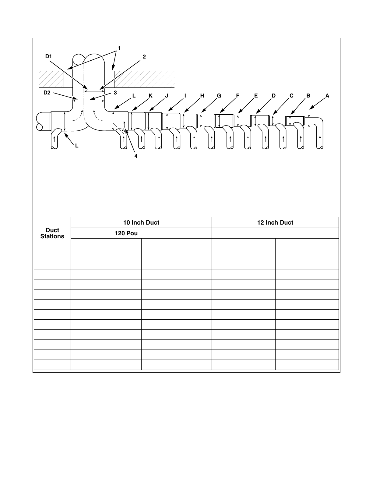
Manifold Venting
While it is preferable to exhaust tumblers individually
to the outdoors, a main collector duct may be used if it
is sized according to Figure 10. This illustration
indicates minimum diameters, and should be increased
if collector length exceeds 20 feet (6.1 meters).
Manifold duct may be rectangular in cross section, as
long as area is not reduced. Provisions should be made
for lint removal and cleaning of duct.
Manifold duct must be tapered, as shown in Figure 9.
Individual tumbler ducts must enter manifold duct at a
45° angle in the direction if airflow.
Never connect a tumbler duct at a 90° angle to a
collector duct. Doing so will cause excessive back
pressure, resulting in poor performance. Never
connect two tumbler exhaust ducts directly across
from each other at the point of entry to manifold
duct.
T438I
Figure 9
Exhaust system must be designed so static back
pressure measured 12 inches (305 mm) from exhaust
thimble does not exceed maximum allowable pressure
specified on installation sticker on rear of tumbler.
This must be measured with all tumblers running that
are vented into collector.
With the tumbler in operation, airflow at any point in
the duct should be at least 1200 feet per minute
(366 meters per minute) to ensure that lint remains
airborne. If 1200 feet per minute cannot be
maintained, schedule a regular inspection and cleaning
of the ductwork.
M414038
© Copyright, Alliance Laundry Systems LLC – DO NOT COPY or TRANSMIT
31
Page 34
Exhaust Requirements
;
;
;
;
D1
1
2
;;;
;;;
D2
;;;;;;;;;
;;;;;;;;;
3
LKJ I HG F E D CB A
L
4
1 NOTE: Where exhaust duct pierces a combustible wall or ceiling, an opening having a diameter 4 in. (102 mm)
larger than diameter of exhaust duct shall be provided, with exhaust duct centered in opening.
2 Outlet for 1 Battery (Diameter same as largest station used.)
3 Outlet for 2 Batteries
4 45° Typi c a l
10 Inch Duct 12 Inch Duct
Duct
Stations
120 Pound Models 170 Pound Models
D1 D2 D1 D2
A 10 in. (254 mm) 15 in. (381 mm) 12 in. (305 mm) 17 in. (432 mm)
B 15 in. (381 mm) 21 in. (533 mm) 17 in. (432 mm) 24 in. (610 mm)
C 18 in. (457 mm) 26 in. (660 mm) 21 in. (533 mm) 30 in. (762 mm)
D 21 in. (533 mm) 30 in. (762 mm) 24 in. (610 mm) 34 in. (864 mm)
E 24 in. (610 mm) 33 in. (838 mm) 27 in. (686 mm) 38 in. (965 mm)
F 26 in. (660 mm) 36 in. (914 mm) 30 in. (762 mm) 42 in. (1067 mm)
G 28 in. (711 mm) 39 in. (991 mm) 32 in. (813 mm) 45 in. (1143 mm)
H 30 in. (762 mm) 42 in. (1067 mm) 34 in. (864 mm) 45 in. (1143 mm)
I 32 in. (813 mm) 45 in. (1143 mm) 36 in. (914 mm) 52 in. (1321 mm)
J 33 in. (838 mm) 47 in. (1194 mm) 38 in. (965 mm) 54 in. (1372 mm)
K 35 in. (889 mm) 49 in. (1245 mm) 40 in. (1016 mm) 57 in. (1448 mm)
L 36 in. (914 mm) 51 in. (1295 mm) 42 in. (1067 mm) 60 in. (1524 mm)
T472I
32
Figure 10
© Copyright, Alliance Laundry Systems LLC – DO NOT COPY or TRANSMIT
M414038
Page 35

Exhaust Requirements
2
3
CONNECT TO TUMBLER
1
2
EXHAUST
OUTLET
CONNECT
TO TUMBLER
5
1
4
3
VERTICAL EXHAUST INSTALLATION
4
T414I
HORIZONTAL EXHAUST INSTALLATION
T414I
1 No Screen or Cap
2 Wall
3 2 in. (51 mm) Minimum Clearance
4 NOTE: Where exhaust duct pierces a combustible wall or ceiling, an opening having a diameter 4 in. (102 mm)
larger than diameter of exhaust duct shall be provided, with exhaust duct centered in opening.
5 Exhaust Airflow – Maximum Length of Duct: 14 ft. (4.3 m)
Figure 11
M414038
© Copyright, Alliance Laundry Systems LLC – DO NOT COPY or TRANSMIT
33
Page 36

Exhaust Requirements
5
4
CEILING
2
3
Consult your local building code for regulations which may also apply.
NOTE: Inside of duct shall be smooth. Do not use sheet metal screws to join sections.
1 NOTE: Do not install wire mesh or screen in this opening as lint will build up and prevent proper
discharge of air from tumblers.
2 Wall
3 Removable Strip of Panel in Framing Wall to Permit Removal of Tumbler from Framing Wall
4 Partition or Bulkhead
5 Minimum Distance Between Opening and Roof: 36 in. (914 mm)
Figure 12
1
T493I
34
© Copyright, Alliance Laundry Systems LLC – DO NOT COPY or TRANSMIT
M414038
Page 37

Gas Requirements
WARNING
To reduce the risk of fire or explosion, DO
NOT CONNECT THE GAS LINE TO THE
TUMBLER IF THE GAS SERVICE IS NOT
THE SAME AS THAT SPECIFIED ON THE
TUMBLER SERIAL PLATE! It will first be
necessary to convert the gas burner
orifice and gas valve. Appropriate
conversion kits are available.
W060
WARNING
The tumbler and its individual shut-off
valve must be disconnected from the gas
supply piping system during any
pressure testing of that system at test
pressures in excess of 1/2 psig (3.45 kPa).
The tumbler must be isolated from the
gas supply piping system by closing its
individual manual shut-off valve during
any pressure testing of the gas supply
piping system at test pressure equal to or
less than 1/2 psig (3.45 kPa).
W061
IMPORTANT: Any product revisions or conversions
must be made by the Manufacturer’s Authorized
Dealers, Distributors or local service personnel.
WARNING
To reduce the risk of fire or explosion, if
the tumbler is to be connected to
Liquefied Petroleum (L.P.) gas, a vent to
the outdoors must be provided in the
room where the tumbler is installed.
W062
NATURAL GAS service must be supplied at 7.0 ±
1.5 inch water column pressure (1.74 ± 0.37 kPa).
L.P. (Liquefied Petroleum) GAS service must be
supplied at 11 ± 0.3 inch water column pressure
(2.74 ± 0.07 kPa).
EUROPEAN GASES – The above data for Natural
and L.P. Gas does not apply in the EU. Refer to
Installing Gas Drying Tumblers in the European
Union Section.
IMPORTANT: The installation must comply with
local codes or, in the absence of local codes:
● with the latest edition of the “National Fuel
Gas Code,” ANSI Z223.1/NFPA 54 in the
U.S.A.,
● with CSA-B149.1 Natural Gas and Propane
Installation Code in Canada,
● and Australian Gas Association/Australian
L.P. Gas Association requirements in
Australia.
Obtain specific gas service pipe size from the gas
supplier. Refer to Table 7 for general pipe size.
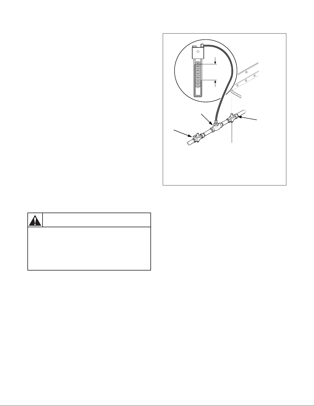
A dirt and water vapor pipe trap must be furnished and
installed by customer. Refer to Figure 13.
Install a 1 inch (25.4 mm) pipe gas loop to maintain
equal pressure at all gas connections. Refer to
Figure 14.
M414038
© Copyright, Alliance Laundry Systems LLC – DO NOT COPY or TRANSMIT
1
1 Gas Line to Tumbler Controls
2 Shut-Off Valve
3 Gas Supply Piping System
4 Gas “T” Fitting
5 6 in. (152 mm) Minimum Gas Pipe
6 Gas Pipe Cap
7 Dirt and Water Vapor Trap
8 1/8 in. (3.2 mm) NPT plugged tapping
2
8
accessible for pressure testing. Gauge
connection located upstream from tumbler
gas supply connection.
3
4
5
7
6
Figure 13
T378I
T135I
35
Page 38

Gas Requirements
Pressure checks can be made at the shut-off valve
(refer to Figure 14).
Turn on gas and check all pipe connections (internal
and external) for gas leaks with a non-corrosive leak
detection fluid.
Purge air in gas service line by operating the tumbler
in the drying mode.
If burner does not light and unit goes into lockout,
open and close the door and restart. Repeat these steps
until burner ignites. Use pipe compound, resistant to
actions of L.P. Gas, on all pipe threads.
WARNING
Check all pipe connections, internal and
external, for gas leaks using a noncorrosive leak detection fluid. To reduce
the risk of explosion or fire, DO NOT USE
AN OPEN FLAME TO CHECK FOR GAS
LEAKS! Gas connections should be
checked annually for leakage.
W314
36
© Copyright, Alliance Laundry Systems LLC – DO NOT COPY or TRANSMIT
M414038
Page 39

Gas Supply Pipe Sizing and
Looping
1
Gas Requirements
3
2
9
1 Gas Furnace (120,000 Btu/hr)
2 Gas Water Heaters (400,000 Btu/hr each)
3 Gas Space Heaters (70,000 Btu/hr each)
4 Pressure Tap
5 1 in. (25.4 mm) Gas Pipe Loop
6 19 ft. (5.8 m)’
7 Minimum Pipe Size to Tumbler is 3/4 in. for 120FG, 1 in. for 170FG
8 25 ft. (7.6 m)
9 Main Regulator
10 Gas Meter
11 Pressure Regulator (If required)
12 Shut-Off Valves
13 120 Pound Tumblers (300,000 Btu/hr each)
SAMPLE CALCULATIONS:
Equivalent length = Total length of main gas supply pipe to the far end of the tumblers.
Total Btu/hr = The sum of the Btu/hr of all 120 pound tumblers being fed by the main gas supply pipe.
Using Tabl e 7 , the main supply pipe diameter should be 3 in. (76 mm).
10
8
170 Pound Tumblers (395,000 Btu/hr each)
= 25 ft. + 19 ft. (7.6 m + 5.8 m) gas supply pipe
= 44 ft. (13.4 m) total gas line
= 9 x 300,000
= 2,700,000 Btu/hr
11
12
7
13
6
4
5
T494I
IMPORTANT: Gas loop piping must be installed as illustrated to equalize gas pressure for all tumblers
connected to single gas service. Other gas using appliances should be connected upstream from loop.
IMPORTANT: Line pressure must be maintained at 7 ± 1 water column inches (1.74 ± 0.23 kPa) for
Natural Gas (11 + 0.3 water column inches for L.P. [Liquefied Petroleum] Gas) (2.74 ± 0.07 kPa) with
all gas appliances running (tumblers, water heaters, space heaters, furnace, etc.).
An in-line pressure regulator may be required on Natural Gas models if the line pressure exceeds 8 water
column inches (2.00 kPa) pressure with all gas appliances firing.
Figure 14
M414038
© Copyright, Alliance Laundry Systems LLC – DO NOT COPY or TRANSMIT
37
Page 40

Gas Requirements
High Altitude Orifice Sizing
For proper operation at altitudes above 2000 feet
(610 meters), the gas orifice size must be reduced to
ensure complete combustion. For CE Marked models,
consult local gas supplier.
Non-CE Marked Models
Model Gas
2001 – 4000 610 – 1220 14 0.1820 4.6
Natural
Gas
120FG
L.P.
Gas
Natural
Gas
170FG
L.P.
Gas
* Btu/hr derate of 4% per 1000 ft. (305 m) of altitude.
4001 – 6000 1221 – 1830 16 0.1770 4.5 M411373 252,000
6001 – 8000 1831 – 2440 17 0.1730 4.4 M411374 228,000
8001 – 10,000 2441 – 3050 19 0.1660 4.2 M402995 204,000
2001 – 4000 610 – 1220 35 0.1100 2.8 M402487 276,000
4001 – 6000 1221 – 1830 36 0.1065 2.7 M411375 252,000
6001 – 8000 1831 – 2440 38 0.1015 2.6 M411376 228,000
8001 – 10,000 2441 – 3050 40 0.0980 2.5 M406361 204,000
2001 – 4000 610 – 1220 14 0.1820 4.6
4001 – 6000 1221 – 1830 16 0.1770 4.5 M411373 331,800
6001 – 8000 1831 – 2440 17 0.1730 4.4 M411374 300,200
8001 – 10,000 2441 – 3050 19 0.1660 4.2 M402995 268,600
2001 – 6000 610 – 1830 30 0.1285 3.3
6001 – 8000 1831 – 3050 31 0.1200 3.0 M401017 300,200
Altitude Orifice
feet m No. inches mm Quantity Part No. (Btu/hr)*
New
Rate
M411371 276,000
3
M411371 363,400
4
M401021 363,400
3
Table 6
38
© Copyright, Alliance Laundry Systems LLC – DO NOT COPY or TRANSMIT
M414038
Page 41

Gas Requirements
Gas
Appliances
Total
Btu/hr.
300,000
400,000
500,000
600,000
700,000
800,000
900,000
1,000,000
1,100,000
1,200,000
1,300,000
1,400,000
1,500,000
1,600,000
1,700,000
1,800,000
1,900,000
2,000,000
2,200,000
2,400,000
2,600,000
2,800,000
3,000,000
3,200,000
3,400,000
3,600,000
3,800,000
4,000,000
Gas Pipe Size Required for 1000 Btu Natural Gas – .64 Specific Gravity
at 7 to 9 inches Water Column Pressure (1.74 ± 2.241 kPa)
Equivalent Length
25 feet
(7.63 m)
50 feet
(15.25 m)
75 feet
(22.88 m)
100 feet
(30.50 m)
125 feet
(38.13 m)
Based on 0.3 in. Water Column Pressure Drop for Length Given
Sizes shown in inches (mm)
1 (25.40)
1.25 (31.75)
1.25 (31.75)
1.5 (38.10)
1.5 (38.10)
1.5 (38.10)
2 (50.80)
2 (50.80)
2 (50.80)
2 (50.80)
2 (50.80)
2 (50.80)
2 (50.80)
2 (50.80)
2 (50.80)
2.5 (63.50)
2.5 (63.50)
2.5 (63.50)
2.5 (63.50)
2.5 (63.50)
2.5 (63.50)
2.5 (63.50)
2.5 (63.50)
3 (76.20)
3 (76.20)
3 (76.20)
3 (76.20)
3 (76.20)
1.25 (31.75)
1.25 (31.75)
1.5 (38.10)
1.5 (38.10)
2 (50.80)
2 (50.80)
2 (50.80)
2 (50.80)
2 (50.80)
2 (50.80)
2.5 (63.50)
2.5 (63.50)
2.5 (63.50)
2.5 (63.50)
2.5 (63.50)
2.5 (63.50)
2.5 (63.50)
2.5 (63.50)
3 (76.20)
3 (76.20)
3 (76.20)
3 (76.20)
3 (76.20)
3 (76.20)
3.5 (88.90)
3.5 (88.90)
3.5 (88.90)
3.5 (88.90)
1.25 (31.75)
1.5 (38.10)
1.5 (38.10)
2 (50.80)
2 (50.80)
2 (50.80)
2 (50.80)
2 (50.80)
2.5 (63.50)
2.5 (63.50)
2.5 (63.50)
2.5 (63.50)
2.5 (63.50)
2.5 (63.50)
2.5 (63.50)
3 (76.20)
3 (76.20)
3 (76.20)
3 (76.20)
3 (76.20)
3 (76.20)
3 (76.20)
3.5 (88.90)
3.5 (88.90)
3.5 (88.90)
3.5 (88.90)
3.5 (88.90)
3.5 (88.90)
1.5 (38.10)
1.5 (38.10)
2 (50.80)
2 (50.80)
2 (50.80)
2 (50.80)
2.5 (63.50)
2.5 (63.50)
2.5 (63.50)
2.5 (63.50)
2.5 (63.50)
2.5 (63.50)
2.5 (63.50)
3 (76.20)
3 (76.20)
3 (76.20)
3 (76.20)
3 (76.20)
3 (76.20)
3 (76.20)
3.5 (88.90)
3.5 (88.90)
3.5 (88.90)
3.5 (88.90)
3.5 (88.90)
3.5 (88.90)
4 (101.60)
4 (101.60)
1.5 (38.10)
1.5 (38.10)
2 (50.80)
2 (50.80)
2 (50.80)
2.5 (63.50)
2.5 (63.50)
2.5 (63.50)
2.5 (63.50)
2.5 (63.50)
2.5 (63.50)
3 (76.20)
3 (76.20)
3 (76.20)
3 (76.20)
3 (76.20)
3 (76.20)
3 (76.20)
3.5 (88.90)
3.5 (88.90)
3.5 (88.90)
3.5 (88.90)
3.5 (88.90)
3.5 (88.90)
4 (101.60)
4 (101.60)
4 (101.60)
4 (101.60)
150 feet
(45.75 m)
1.5 (38.10)
2 (50.80)
2 (50.80)
2 (50.80)
2.5 (63.50)
2.5 (63.50)
2.5 (63.50)
2.5 (63.50)
2.5 (63.50)
2.5 (63.50)
3 (76.20)
3 (76.20)
3 (76.20)
3 (76.20)
3 (76.20)
3 (76.20)
3 (76.20)
3.5 (88.90)
3.5 (88.90)
3.5 (88.90)
3.5 (88.90)
3.5 (88.90)
4 (101.60)
4 (101.60)
4 (101.60)
4 (101.60)
4 (101.60)
4 (101.60)
FOR L.P. (LIQUEFIED PETROLEUM) GAS, CORRECT THE TOTAL BTU/HR. BY MULTIPLYING IT BY 0.6.
THE ANSWER IS THE EQUIVALENT BTU ON THE ABOVE CHART.
IMPORTANT: The installation must conform with local codes or, in the absence of local codes:
● with the latest edition of the “National Fuel Gas Code,” ANSI Z223.1/NFPA 54 in the U.S.A.,
● with CSA-B149.1 or Natural Gas and Propane Installation Code in Canada,
● and Australian Gas Association/Australian L.P. Gas Association requirements in Australia.
Table 7
M414038
© Copyright, Alliance Laundry Systems LLC – DO NOT COPY or TRANSMIT
39
Page 42

Gas Requirements
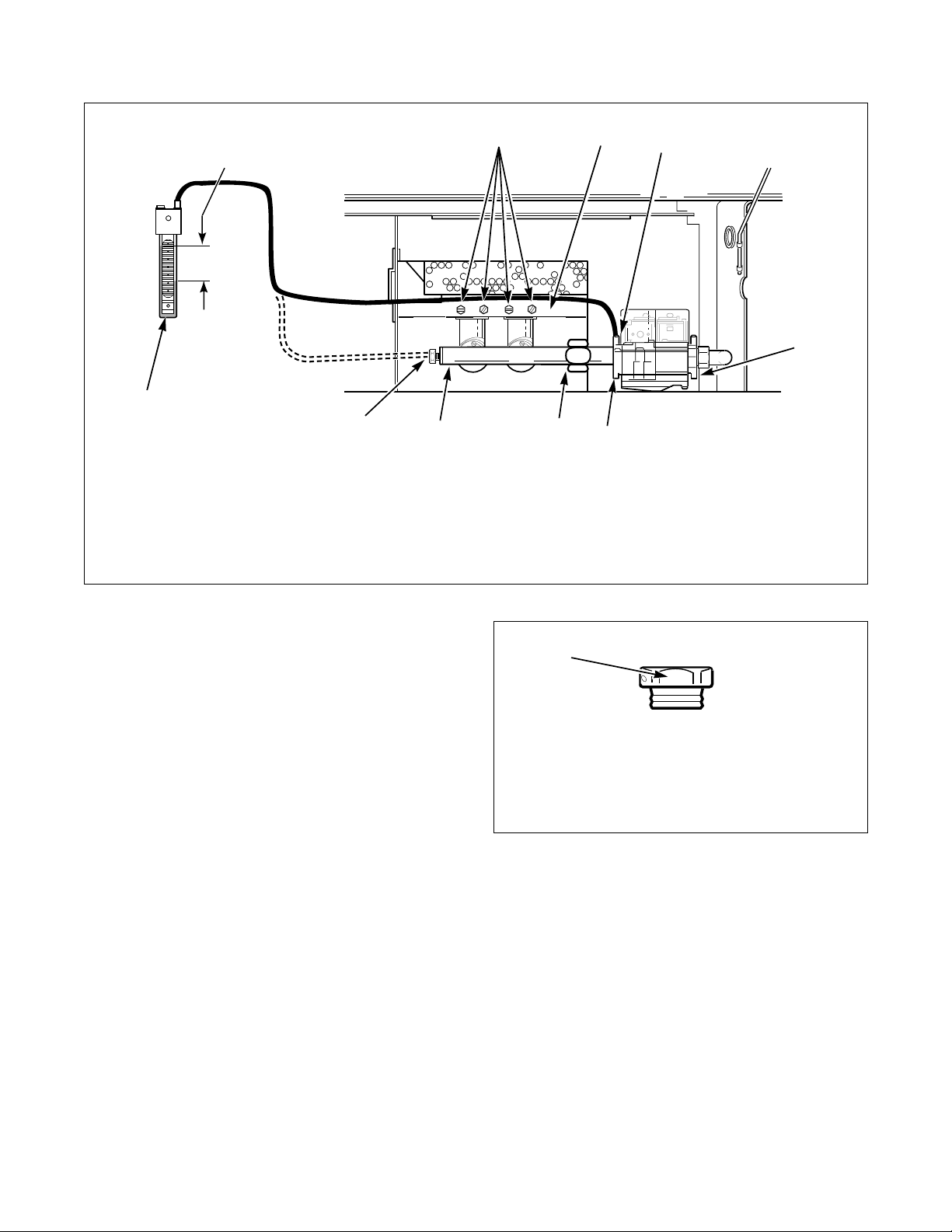
Instant Electronic Ignition System
To light and shut down Instant Electronic Ignition
system:
1. Remove access panel.
2. Turn gas shut-off valve to open position
(handle should be parallel with the gas line).
Refer to Figure 15.
3. Replace access panel.
4. Start tumbler in drying cycle. Spark igniter will
begin high intensity sparking as the gas valve
simultaneously opens. The gas burner(s) are
ignited by the sparking igniter. Igniter will shut
off, and burner(s) will remain on as long as the
temperature control calls for heat.
5. Opening the tumbler door will cause flame to
extinguish. Closing door and starting tumbler
will restart ignition cycle.
2
3
IMPORTANT: The Instant Electronic Ignition
system will attempt to light the gas by sparking for
approximately 15 seconds. If gas ignition does not
take place within 15 seconds the Instant Electronic
Ignition control will go into safety lockout and the
valve will no longer open until the Instant
Electronic Ignition control is reset. To reset Instant
Electronic Ignition control, remove power from
control by opening and closing the loading door. If
condition persists, check that the gas shut-off valve
is in open position and that the gas service is
properly connected. If condition still persists,
remove tumbler from service.
6. To remove tumbler from service, disconnect
electrical service, and turn gas shut-off valve to
closed position (handle should be at right angle to
the gas line).
1
7
6
1 Closed Position 5 Burner Support Bracket
2 Open Position 6 Spud Holder
3 Gas Shut-Off Valve 7 Union Nut
4 Manometer
Figure 15
5
4
T087K
T087K
40
© Copyright, Alliance Laundry Systems LLC – DO NOT COPY or TRANSMIT
M414038
Page 43

Steam Requirements
Obtain specific steam service pipe sizes from steam
system supplier or a qualified steam fitter.
● Refer to Figure 16 and Figure 17 for proper
steam pipe configurations.
● To prevent condensate draining from headers to
tumbler, piping should have a minimum 12 inch
(305 mm) rise above respective header. Do not
make steam connection to header with a
horizontal or downward facing tee or elbow.
● Whenever possible, horizontal runs of steam
lines must drain, by gravity, to respective steam
header. Water pockets or an improperly drained
steam header will provide wet steam, causing
improper operation of tumbler. If pockets or
improper drainage cannot be eliminated, install a
bypass trap to drain condensate from the low
point in the steam header to the return.
● In both steam supply and steam return line, it is
recommended that each have a pipe union and
globe valve. This will enable you to disconnect
the steam connections and service the tumbler
while your laundry facility is in operation.
● Before connecting trap and check valve to
tumbler, open shut-off valve in steam supply line
and allow steam to flow through tumbler to flush
out any dirt and scale from tumbler. This will
assure proper operation of trap when connected.
● After flushing system, install vacuum breaker,
bucket trap (with built-in strainer) and check
valve. For successful operation of tumbler, install
trap 18 inches (457 mm) below coil and as near
to the tumbler as possible. Inspect trap carefully
for inlet and outlet markings and install
according to trap manufacturer’s instructions. If
steam is gravity returned to boiler, omit trap but
install vacuum breaker and check valve in return
line near tumbler.
● Install union and shut-off valve in return line and
make final pipe connections to return header.
M414038
© Copyright, Alliance Laundry Systems LLC – DO NOT COPY or TRANSMIT
41
Page 44

Steam Requirements
All system components must have a
125 psig (10 bar) working pressure.
Shut-off gate valves must be installed
upstream of the steam solenoid valve and
downstream of each steam trap so
components can be isolated for
maintenance or emergency purposes.
All components (solenoid valve, traps)
must be supported to minimize loads on
the tumbler steam coil connections.
W438
WARNING
Piping Recommendations
● Trap each steam coil individually. Always keep
the trap clean and in good working condition.
● When tumbler is on the end of a line of
equipment, extend header at least 4 feet
(1.2 meters) beyond tumbler. Install shut-off
valve, union, check valve and bypass trap at end
of line. If gravity return to boiler, omit trap.
● Insulate steam supply and return line for safety of
operator and safety while servicing tumbler.
● Keep tumbler in good working condition. Repair
or replace any worn or defective parts.
NOTE: Steam heated tumbler models are not
certified by the American Gas Association or the
Canadian Gas Association.
High pressure machines require a (constant)
80-100 psig (pounds per square inch gauge)
(5.62-7.03 kg/cm
operation.
2
) steam service for optimum
Installing Steam Trap and Making
Condensate Return Connections
The steam trap must be installed and the coil outlet
connections must be connected to the condensate
return lines. The following steps outline the procedure
for installing the steam trap and connecting the
condensate return lines. Refer to Figure 16 and
Figure 17 for typical installations.
1. Connect a flexible hose to each steam coil outlet.
2. Install a strainer to the ends of each flexible hose.
3. Install a steam trap to each strainer.
IMPORTANT: Steam trap must be installed a
minimum of 10 inches (254 mm) below the steam
coil outlet connections.
4. Install a globe shut-off valve to each steam trap.
5. Connect to the condensate return lines.
42
© Copyright, Alliance Laundry Systems LLC – DO NOT COPY or TRANSMIT
M414038
Page 45

120 Pound Tumblers
SUPPLY
Steam Requirements
1
2
9
3
2
10
5
8
NOTE: Sizing of pipe diameters is shown for steam at rated pressure of 120 psi. Pipe diameter needs to be increased
accordingly if pressure is less than 125 psi (refer to Tab l e 8 ). Piping must also be sized accordingly for length of runs
and number of elbows.
1 Risers 12 in. (305 mm) 6 18 in. Drop (457 mm)
2 Shut-Off Valve 7 Solenoid Valve (Supplied with machine)
3 Check Valve 8 Steam Bonnet
4 Condensate Return Line from Supply Line 9 Union
5 Vacuum Breaker 10 Trap with Built-In Strainer
7
6
5
4
3
RETURN
T221I
T221I
Figure 16
Model
Steam Pressure
(psi)
Minimum Pipe Diameter
Steam Trap Size
(Pounds Condensate/Hour)
120CSH 120 – 125 1 in. (25 mm) 345
120CSH 60 – 120 1 in. (25 mm) 345
120CSH 35 – 60 1.25 in. (32 mm) 345
Table 8
M414038
© Copyright, Alliance Laundry Systems LLC – DO NOT COPY or TRANSMIT
43
Page 46

Steam Requirements
170 Pound Tumblers
SUPPLY
8
1
2
9
3
7
6
5
4
3
NOTE: Sizing of pipe diameters is shown for steam at rated pressure of 120 psi. Pipe diameter needs to be increased
accordingly if pressure is less than 125 psi (refer to Tab l e 9 ). Piping must also be sized accordingly for length of runs
and number of elbows.
1 Risers 12 in.
2 Shut-Off Valve 7 Steam Bonnet
3 Check Valve 8 Solenoid Valve (Supplied with machine)
4 Vacuum Breaker 9 Union
5 Condensate Return Line from Supply Line 10 Trap with Built-In Strainer
(305 mm) 6 18 in. Drop (457 mm)
10
RETURN
2
T497I
Figure 17
Model
Steam Pressure
(psi)
Minimum Pipe Diameter
Steam Trap Size
(Pounds Condensate/Hour)
170CSH 110 – 125 1 in. (25 mm) 517
170CSH 60 – 110 1.25 in. (32 mm) 517
170CSH 35 – 60 1.5 in.(38 mm) 517
44
Table 9
© Copyright, Alliance Laundry Systems LLC – DO NOT COPY or TRANSMIT
M414038
Page 47

Electrical Requirements
To reduce the risk of electric shock, fire,
explosion, serious injury or death:
• Disconnect electric power to the tumbler
before servicing.
• Close gas shut-off valve to gas tumbler
before servicing.
• Close steam valve to steam tumbler
before servicing.
• Never start the tumbler with any guards/
panels removed.
• Whenever ground wires are removed
during servicing, these ground wires
must be reconnected to ensure that the
tumbler is properly grounded.
W002
To reduce the risk of fire and electric
shock, check with a qualified serviceman
for proper grounding procedures.
Improper connection of the equipment
grounding conductor may result in a risk
of electric shock.
W068
To reduce the risk of fire and electric
shock, if electrical supply is coming from a
three phase service, DO NOT connect a
“High Leg” or “Stinger Leg” to a single
phase machine. On a three phase machine,
if there is a “High Leg” or “Stinger Leg” it
should be connected to L3.
W069
WARNING
Grounding Instructions
This tumbler must be grounded. In the event of
malfunction or breakdown, grounding will reduce the
risk of electric shock by providing a path of least
resistance for electric current. This tumbler must be
connected to a grounded metal, permanent wiring
system; or an equipment grounding conductor must be
run with the circuit conductors and connected to the
appropriate ground location.
Metal conduit and/or BX cable is not considered
ground. Connecting the Neutral from the electrical
service box to the tumbler ground screw does not
constitute a ground. A dedicated ground conduit (wire)
must be connected between the electrical service box
ground bar and the tumbler ground screw.
WARNING
All electrical connections should be made
by a qualified electrician.
NOTE: To ensure protection against shock, this
tumbler MUST be electrically grounded in
accordance with the local codes or, in the absence of
local codes, with the latest edition of the National
Electrical Code ANSI/NFPA No. 70. In Canada the
electrical connections are to be made in accordance
with CSA C22.1 latest edition Canadian Electrical
Code, Part I and/or local codes. Electrical work
should be done by a qualified electrician.
M414038
© Copyright, Alliance Laundry Systems LLC – DO NOT COPY or TRANSMIT
To reduce the risk of electrical shock, deenergize the electrical circuit being
connected to the tumbler before making
any electrical connections. Never attempt
to connect a live circuit.
W070
CAUTION
Label all wires prior to disconnection when
servicing controls. Wiring errors can
cause improper and dangerous operation.
Verify proper operation after servicing.
W071
45
Page 48

Electrical Requirements
For CE Marked Models Only
All manually operated models are factory-equipped
with an emergency stop button on the front panel.
NOTE: Activation of the emergency stop switch
stops all machine control circuit functions, but
DOES NOT remove all electrical power from
machine.
To Connect Electrical Service to the
Tumbler
NOTE: The wiring diagram is supplied in
literature packet in cylinder.
1. Install a circuit breaker as close to the tumbler as
possible. If more than one tumbler is being
installed, a disconnect switch or circuit breaker
should be provided for each. This will make it
possible to disconnect each tumbler for
maintenance purposes.
2. Connect conduit-encased leads to the disconnect
switch or circuit breaker. Connect wire leads to
the appropriate labeled terminal on the terminal
block. The ground wire must be connected to the
ground connection as shown in Figure 18.
3. Check the electrical service phase sequence
(three phase only) as follows:
NOTE: On reversing tumblers, the fan motor
rotates counterclockwise (viewed from the front).
b. Disconnect and reverse any two leads at
connections.
2
1
4
NON-CE MARKED MODELS
1 Contactor Box or Junction Box
2 Electrical Service
3 Fuses
4 Ground Screw
2
3
T390i
T390I
a. If one of the power leads is a “high leg,”
connect it to lead L3 in the tumbler. The
cylinder must rotate clockwise and the fan
must rotate counterclockwise (as viewed from
the front of the tumbler – with selector switch
in non-reverse position). If not, interchange
leads L1 and L2 in the tumbler connection
box.
1
4
3
CE MARKED MODELS
Figure 18
3
TMB1275N
46
© Copyright, Alliance Laundry Systems LLC – DO NOT COPY or TRANSMIT
M414038
Page 49

Electrical Requirements
Jumper Configuration Instructions
OPL Micro Control Models Only
Changing the transformer configuration jumper is
required if any of the following apply:
● You have 208 Volt service and are connecting a
gas or steam model rated for 208 Volt or
240 Volt.
● You have 415 Volt service and are connecting a
gas or steam model rated for 380 Volt or
415 Volt.
To configure your 208 Volt or 240 Volt tumbler for
208 Volt operation, you must remove the 240 Volt
configuration jumper located in the contactor box and
replace it with the 208 Volt jumper supplied with the
literature packet. This must be done prior to supplying
power to the machine. Failure to install proper
configuration jumper may result in damage to sensitive
electronic controls and may void warranty.
To configure your 380 Volt or 415 Volt tumbler for
415 Volt operation, you must remove the 380 Volt
configuration jumper located in the contractor box and
replace it with the 415 Volt jumper supplied with the
literature packet. This must be done prior to supplying
power to machine. Failure to install proper
configuration jumper may result in damage to sensitive
electronic controls any may void warranty.
Ferrite Ring Installation
OPL Micro Control Models Only
The ferrite ring provided in the literature packet must
be installed over the power leads during connection of
electrical service. The ferrite protects the sensitive
electronic controls from destructive electrical
disturbances which may be present on power lines to
the machine. Failure to properly install the ferrite ring
may result in damage to the electronic controls and
will void control warranty.
To Install:
1. Immediately after connection of power leads and
before applying power to machine, locate each of
the incoming service leads including ground.
2. Snap the ferrite ring closed over all the service
leads inside of the contactor box as shown. It is
important that the ferrite ring be installed inside
the contactor box. Refer to Figure 19. Do not
install the ferrite outside of the box or other area.
Make sure that service leads are in the center of
the ferrite before closing the ring so not to pinch
or damage leads.
2
1
3
T225S
1 Contactor Box
2 Ferrite Ring
3 Jumper
Figure 19
M414038
© Copyright, Alliance Laundry Systems LLC – DO NOT COPY or TRANSMIT
47
Page 50

Electrical Requirements
Electrical Requirements
Refer to Table 10.
NOTE: Minimum wire sizes are obtained from
NOTE: Connect to an individual branch circuit.
NOTE: Use copper conductors only.
Canadian Electrical Code and are intended for use
as a guideline only. Electrical connections should be
made only by a qualified electrical contractor in
accordance with all applicable local and national
requirements.
120 Pound Tumbler Model
Serial Plate Voltage
Terminal Block
Connections Required
208 – 230V/60Hz/3ph L1, L2, L3 and ground 6.7 10 Amps 3 14 AWG (2.6 mm
380 – 415V/50Hz/3ph L1, L2, L3 and ground 4.7 10 Amps 3 14 AWG (2.6 mm
460 – 480V/60Hz/3ph L1, L2, L3 and ground
Rated
Current*
Breaker
Rating
4.0 10 Amps 3
Breaker
Poles
Recommended
Wire Size
14 AWG (2.6 mm
170 Pound Tumbler Model
Serial Plate Voltage
Terminal Block
Connections Required
208 – 230V/60Hz/3ph L1, L2, L3 and ground 12.7 15 Amps 3 14 AWG (2.6 mm
380 – 415V/50Hz/3ph L1, L2, L3 and ground 7.3 10 Amps 3 14 AWG (2.6 mm
460 – 480V/60Hz/3ph L1, L2, L3 and ground 6.6 10 Amps 3 14 AWG (2.6 mm
Rated
Current
Breaker
Rating
Breaker
Poles
Recommended
Wire Size
2
)
2
)
2
)
2
)
2
)
2
)
* Current ratings vary slightly depending on model; refer to serial plate.
Tab l e 10
48
© Copyright, Alliance Laundry Systems LLC – DO NOT COPY or TRANSMIT
M414038
Page 51

Adjustments
Gas Burner Air Shutter
NOTE: Air inlet shutters on the burner must be
adjusted so sufficient air is metered into the system
for proper combustion and maximum efficiency.
Before adjusting the inlet shutters, be sure that all
lint is removed from lint compartments and lint
screen.
Air shutter adjustment will vary from location to
location and will depend on the vent system, number
of units installed, make-up air and line gas pressure.
Opening the shutter increases the amount of primary
air supplied to the burner, while closing the shutter
decreases the primary air supply. Adjust air shutter as
follows:
1. Remove the upper access panel.
2. Start the tumbler and check the flame pattern.
Correct air and gas mixture is indicated if the
flame pattern is primarily blue, with small yellow
tips, and bends to the left of the heater section
(refer to Figure 20). Too little air is indicated if
the flame is yellow, lazy and smoky. A flame
pattern that flares to the right and left (refer to
Figure 20) indicates no air is flowing through the
tumbler.
PROPER AIRFLOW
1
INSUFFICIENT AIRFLOW
1
NO AIRFLOW
3. To adjust the air shutter, loosen air inlet shutter
adjusting screw (refer to Figure 20).
4. Open or close air shutter as necessary to obtain
proper flame intensity.
5. After air shutter is adjusted for proper flame,
tighten air shutter adjusting screw securely.
6. If the flame pattern is straight up (refer to
Figure 20), insufficient primary air is flowing
through the tumbler and airflow switch is
improperly set.
1
T464I
1 Air Shutter Adjusting Screw
Figure 20
M414038
© Copyright, Alliance Laundry Systems LLC – DO NOT COPY or TRANSMIT
49
Page 52

Adjustments
2
3
4
5
1
6
FOR 120 POUND TUMBLERS ONLY
Airflow Light
Manual Timer Models Only
The light on the front control indicates when the
airflow through the tumbler is less than normal. When
this light flickers on and off or stays on all the time,
the tumbler cannot operate properly.
If cleaning the lint screen does not correct the
problem, other possibilities include: Lint build-up in
the exhaust line or discharge vent, incorrect rotation of
blower, lack of make-up air, jammed backdraft
damper, overloaded tumbler or anything else that will
reduce the airflow.
The airflow light is wired to the normally close contact
of the airflow switch, so when the airflow switch
flutters or does not pull in, the light will advise the
operator that there is a problem, which should be
corrected immediately. It is normal for the light to
come on for two seconds when the tumbler is started.
It should go out when the blower is up to speed.
1
2
3
4
1 Airflow Switch (Non-EU)
2 Airflow Switch (EU)
3 Final Drive Eyebolt
4 Reversing Motor 3/4 Horsepower
5 Drive Motor Eyebolt
6 Blower Motor 1 Horsepower
Figure 21
T173I
FOR 170 POUND TUMBLERS ONLY
1 Airflow Switch
2 Final Drive Eyebolt
3 Reversing Motor 3/4 Horsepower
4 Drive Motor Eyebolt
5 Blower Motor 3 Horsepower
T283i
Figure 22
5
T283I
50
© Copyright, Alliance Laundry Systems LLC – DO NOT COPY or TRANSMIT
M414038
Page 53

Adjustments
Airflow Switch
The airflow switch is set at the factory for proper
operation. No adjustment necesary. Refer to Figure 22.
IMPORTANT: Airflow switch vane must remain
closed during operation. If it opens and closes
during the drying cycle, this indicates insufficient
airflow through the tumbler. If the switch remains
open, or pops open and closed during the cycle, the
heating system will shut off. The cylinder and fan
will continue to operate even though the airflow
switch is indicating insufficient airflow.
Loading Door Switch
Non-CE Marked Models
The door switch should be adjusted so that the cylinder
stops whenever the door is opened a maximum of
3 inches (76.2 mm). A switch is provided inside of the
front panel to govern this operation. The switch is
activated by an adjustable screw on the upper hinge of
the loading door. The screw contacts the switch arm. If
adjustments are required, refer to Figure 23 and
proceed as follows:
1. Slightly loosen the nut on the door switch
activator screw.
2. Using a 5/64 inch hex wrench, turn the door
switch activator screw in or out slightly as
required.
3. Open the door and check the amount of door
opening before shutdown occurs. If not proper,
repeat steps 1 and 2.
1
M414038
1 Door Switch Activator Screw and Nut
Figure 23
© Copyright, Alliance Laundry Systems LLC – DO NOT COPY or TRANSMIT
T218I
51
Page 54

Adjustments
CE Marked Models
The loading door switch is factory adjusted to turn
off tumbler when the door is opened a maximum
of 3 inches (76.2 mm). If adjustment is needed, refer to
Figure 24 and follow these steps.
1. Start tumbler, following the operating
instructions which accompanied it.
2. Slowly open loading door. Cylinder and heating
system should stop when door is open 3 inches
(76.2 mm) maximum.
3. Slowly close loading door while depressing start
switch or pad. Tumbler should start before
loading door is 0.5 inch (13 mm) from fully
closed.
4. If opening the loading door 3 inches (76.2 mm)
maximum does not stop tumbler, adjust switch.
a. Loosen lower screw on switch coupler (use
2 mm hex wrench).
b. Align screw slot with alignment marks on
switch top (switch should be closed, or on).
c. Start tumbler.
1
2
3
T495I
1 Loading Door Switch
2 Screw Slot
3 Switch Coupler
Figure 24
d. Prop door open 2.5 inches (63.5 mm).
e. Slowly rotate switch coupler
counterclockwise (viewed from above switch)
until tumbler stops.
f. Tighten lower screw on switch coupler.
g. Return to step 1 to verify loading door switch
operation.
52
© Copyright, Alliance Laundry Systems LLC – DO NOT COPY or TRANSMIT
M414038
Page 55

Loading Door Strike
2
3
1
The door strike must be adjusted to have sufficient
tension to hold loading door closed against force of
load tumbling against it. Proper adjustment is when
8-15 pounds (35.6-66.7 N) pull is required to open
door.
If adjustment is required, refer to Figure 25 and
proceed as follows:
To adjust, open door, loosen jam nut and turn door
strike screw in or out as required. Retighten jam nut.
Adjustments
WARNING
To reduce the risk of electric shock, fire,
explosion, serious injury or death:
• Disconnect electric power to the tumbler
before servicing.
• Close gas shut-off valve to gas tumbler
before servicing.
• Close steam valve to steam tumbler
before servicing.
• Never start the tumbler with any guards/
panels removed.
• Whenever ground wires are removed
during servicing, these ground wires
must be reconnected to ensure that the
tumbler is properly grounded.
W002
T048I
1 Door Strike
2 Door Latch
3 Jam Nut
M414038
Figure 25
© Copyright, Alliance Laundry Systems LLC – DO NOT COPY or TRANSMIT
53
Page 56

Adjustments
Belt Drive
The drive assemblies consist of motors, belts, eyebolts
and a step pulley.
The pulley diameters are sized to produce a cylinder
speed of 37-39 RPM for 120 pound models or
29-31 RPM for 170 pound models.
The step pulley assembly is used for speed reduction
as well as a means of adjusting belt tension. The pulley
mounting plate is attached to the cabinet. The frame
mounting plate has vertically slotted holes allowing up
and down movement of the step pulley mounting plate
for belt adjustment.
Adjust the belt tension as follows:
1. Disconnect electrical power to the tumbler before
attempting any adjustments to the drive assembly.
2. Loosen the upper nut on the final drive eyebolt.
3. Rotate the lower nut of the final drive eyebolt
clockwise until proper belt tension is achieved.
4. Rotate upper nut clockwise against the lower nut
in order to lock it into place.
5. If necessary, adjust the drive motor belt tension
eyebolt using the same procedure as steps 1-4.
6. Adjust blower belt tension on 120 pound
50 Hertz tumblers and all 170 pound tumblers
using the same procedure as in steps 1-4.
NOTE: Proper tension for new belts is
45-55 pounds for the motor belt and 55-65 pounds
for the final drive, measured with a Borroughs Belt
Tension Gauge. Using a Browning Belt Tension
Gauge, the motor belt deflection should be
5/16 inch at five pounds pressure, and final drive
belt deflection should be 1/4 inch at five pounds
pressure.
Belts should not slip or make any noise when starting
up under normal load.
54
© Copyright, Alliance Laundry Systems LLC – DO NOT COPY or TRANSMIT
M414038
Page 57

Removing Tumbler from Service
If the tumbler is to be removed from service, perform
the following steps where applicable:
● Turn off electrical supply external to machine.
● Turn off electrical disconnect on machine.
● Turn off gas supply external to machine.
● Turn off manual gas shut-off valve on the
machine.
● Turn off steam supply external to machine.
● Remove all electric, gas and steam connections.
M414038
© Copyright, Alliance Laundry Systems LLC – DO NOT COPY or TRANSMIT
55
Page 58

Page 59
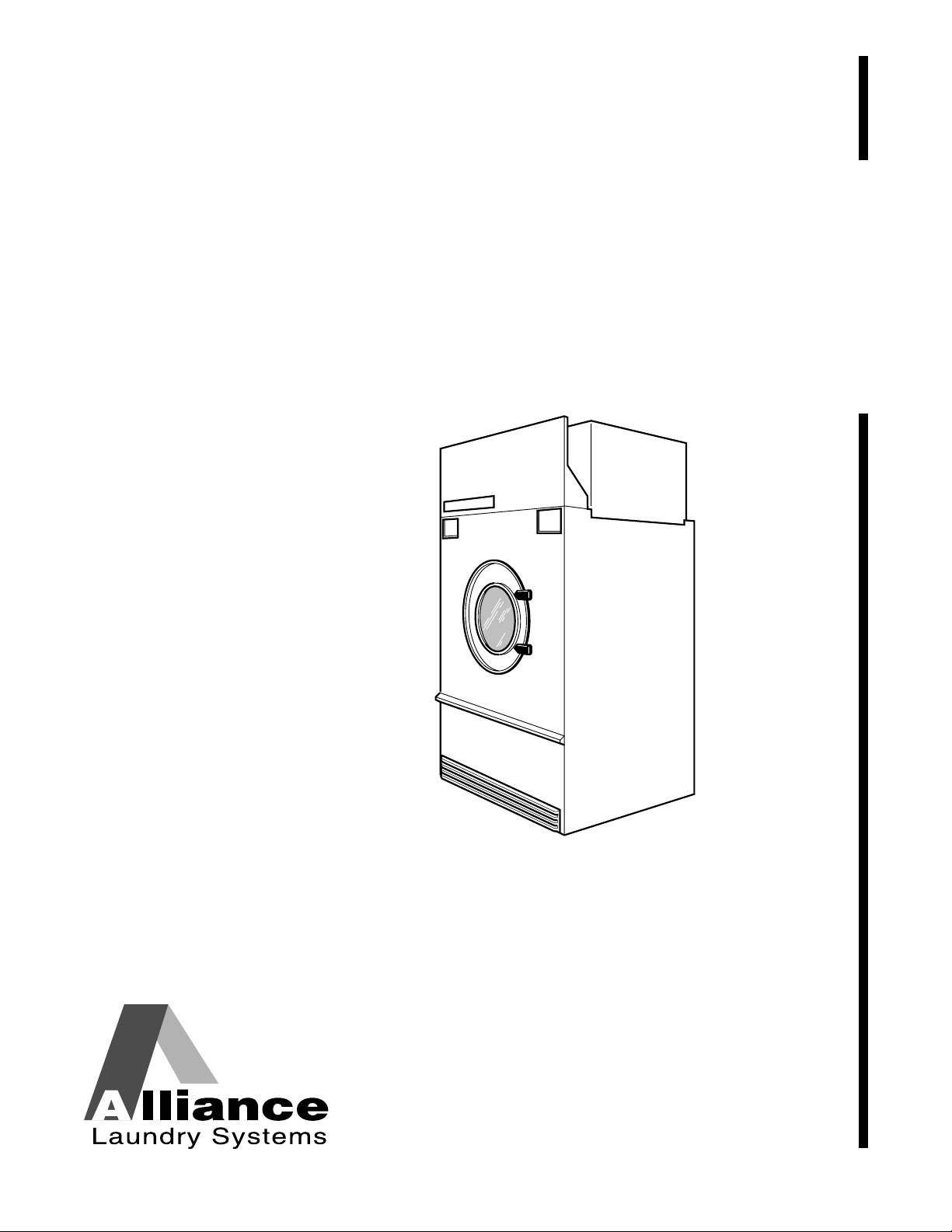
Secadoras
Capacidad de 120 libras
Capacidad de 170 libras
Consulte la página 63 para la identificación de modelos
Instalación
Guarde estas instrucciones para referencia en el futuro.
(Si esta máquina cambia de dueño, asegúrese de que este manual vaya con la misma).
www.comlaundry.com
T433I
Pieza No. M414038
Octubre 2001
Page 60

Page 61

La instalación debe cumplir con los códigos locales o, de no existir códigos locales, con los siguientes códigos:
PARA SU SEGURIDAD, se debe respetar la
información de este manual para reducir a
un mínimo el riesgo de incendios o
explosiones o para prevenir daños
materiales, lesiones graves o mortales.
W033SR1
• No guarde ni use gasolina u otros
vapores y liquidos inflamables en las
proximidades de este u otro aparato.
• QUÉ DEBE HACER SI HUELE A GAS:
– No trate de encender ningún aparato.
– No toque ningún interruptor eléctrico;
no use ningún teléfono del edificio.
– Haga salir a todos los ocupantes de la
sala, edificio o área.
– Llame inmediatamente a su proveedor
de gas desde el teléfono de un vecino.
Siga las instrucciones del proveedor de
gas.
– Si no puede ponerse en contacto con
su proveedor de gas, llame al
departamento de bomberos.
• La instalación y el servicio deben ser
llevados a cabo por un instalador,
agencia de servicio o proveedor de gas
cualificados.
W052SR1
PARA SU SEGURIDAD
No guarde ni use la gasolina u otros
vapores y líquidos inflamables en las
proximidades de ésta o cualquier otro
aparato.
W053SR1
ADVERTENCIA
En EE.UU.
, la instalación debe cumplir con la última edición de la American National Standard Z223.1/
NFPA y con la norma ANSI/NFPA 70 “National Electric Code”.
En Canadá
, la instalación debe cumplir con las normas CSA-B149.1 o el código para gas natural y propano
CSA C22.1, última edición, Canadian Electric Code, Part I.
En Australia
, la instalación debe cumplir con el Australian Gas Association Installation Code para aparatos
y equipos de combustión de gas.
IMPORTANTE: Se debe obtener la información de un proveedor de gas local sobre las instrucciones que
deben seguirse si el usuario percibe olor a gas. Estas instrucciones deben colocarse en un lugar a la vista de
todos. Las instrucciones paso a paso de la información de seguridad anterior debe colocarse a la vista cerca
de la secadora para uso del cliente.
© Copyright, Alliance Laundry Systems LLC – DO NOT COPY or TRANSMITM414038 (SP)
MISE EN GARDE
POUR VOTRE SÉCURITÉ il est impératif de
suivre les instructions de ce manuel pour
minimiser les risques d’incendie ou
d’explosion et pour éviter les dommages
matériels, les blessures corporelles ou la
mort.
W033Q
• Ne pas entreposer ni utiliser d’essence ni
d’autres vapeurs ou liquides
inflammables dans le voisinage de cet
appareil ou de tout autre appareil.
• QUE FAIRE SI VOUS SENTEZ UNE
ODEUR DE GAZ :
– Ne pas tenter d’allumer d’apareil.
– Ne touchez à aucun interrupteur. Ne
pas vous servir des téléphones se
trouvant dans le bâtiment où vous vous
trouvez.
–Évacuez la pièce, le bâtiment ou la
zone.
– Appelez immédiatement votre
fournisseur de gaz depuis un voisin.
Suivez les instructions du fournisseur.
– Si vous ne pouvez rejoindre le
fournisseur de gaz, appelez le service
des incendies.
• L’installation et l’entretien doivent être
assurés par un installateur ou un service
d’entretien qualifié ou par le fournisseur
de gaz.
W052Q
POUR VOTRE SÉCURITÉ
Ne pas entreposer ni utiliser d’essence ni
d’autres vapeurs ou liquides inflammables
dans le voisinage de cet appareil ou de tout
autre appareil.
W053Q
59
Page 62

Notas
60
© Copyright, Alliance Laundry Systems LLC – DO NOT COPY or TRANSMIT
M414038 (SP)
Page 63

Contenido
Introducción ........................................................................................ 63
Identificación de modelos..................................................................... 63
Servicio al cliente ................................................................................. 63
Diagrama de conexiones....................................................................... 63
Ubicación de la placa del número de serie ........................................... 64
Información de seguridad.................................................................. 65
Instrucciones importantes de seguridad................................................ 66
Especificaciones y dimensiones.......................................................... 69
Dimensiones de la secadora de 120 libras y posiciones de la
salida de escape.................................................................................. 70
Dimensiones de la secadora de 170 libras y posiciones de la
salida de escape.................................................................................. 71
Posiciones de las conexiones eléctricas y de gas para los
modelos FG ........................................................................................ 72
Posiciones de las conexiones eléctricas y de vapor para los
modelos CSH...................................................................................... 73
Instalación ........................................................................................... 75
Inspección anterior a la instalación....................................................... 75
Requisitos de localización .................................................................... 76
Coloque y nivele la secadora ................................................................ 77
Antes de poner la secadora en servicio................................................. 77
Instalación de secadoras de gas en la Unión Europea (UE) ................. 79
Información general......................................................................... 79
Configuración básica ....................................................................... 80
Procedimientos de conversión específicos....................................... 81
Requisitos de escape ........................................................................... 87
Disposición ........................................................................................... 87
Aire de complemento............................................................................ 87
Ventilación............................................................................................ 87
Ventilación individual...................................................................... 89
Ventilación con conducto colector................................................... 89
Requisitos de gas................................................................................. 93
Tamaño del tubo y circuito de suministro de gas ................................. 95
Tamaño del orificio de elevada altitud ................................................. 96
Sistema de encendido electrónico instantáneo ..................................... 98
Requisitos de vapor............................................................................. 99
Tuberías recomendadas ........................................................................ 100
Instalación de un purgador de condensado y conexiones de
retorno de condensado........................................................................ 100
Secadoras de 120 libras ........................................................................ 101
Secadoras de 170 libras ........................................................................ 102
© Copyright 2001, Alliance Laundry Systems LLC
Todos los derechos reservados. Ninguna sección del presente manual puede reproducirse o transmitirse en forma
alguna o a través de ningún medio sin el consentimiento expreso por escrito del editor.
© Copyright, Alliance Laundry Systems LLC – DO NOT COPY or TRANSMITM414038 (SP)
61
Page 64

Requisitos eléctricos............................................................................ 103
Instrucciones para la puesta a tierra...................................................... 103
Para modelos marcados con CE solamente ..................................... 104
Para conectar el servicio eléctrico a la secadora.............................. 104
Instrucciones de configuración del puente ........................................... 105
Instalación del anillo de ferrita ............................................................. 105
Requisitos eléctricos............................................................................. 106
Ajustes.................................................................................................. 107
Obturador de aire del quemador de gas ................................................ 107
Luz de flujo de aire............................................................................... 108
Interruptor de flujo de aire.................................................................... 109
Interruptor de la puerta de carga........................................................... 109
Placa de cierre de la puerta de carga..................................................... 111
Mando de la correa ............................................................................... 112
Puesta de la secadora fuera de servicio............................................. 113
62
M414038 (SP)© Copyright, Alliance Laundry Systems LLC – DO NOT COPY or TRANSMIT
Page 65

Introducción
Identificación de modelos
La información de este manual corresponde a estos
modelos:
Gas Vapor/aceite térmico Eléctrica
AT120FG AT120CSH No se aplica
DT120FG DC120CSH
DT120FG DT120CSH
JC120FG JC120CSH
120 libras
170 libras
JT120FG JT120CSH
ST120FG SC120AT
ST120FG ST120CSH
AT170FG AT170CSH No se aplica
DC170FG DC170CSH
DT170FG DT170CSH
JC170FG JC170CSH
JT170FG JT170CSH
SC170FG SC170CSH
ST170FG ST170CSH
ST120AT
ST120CSH
Servicio al cliente
Si necesita más información escrita o repuestos,
póngase en contacto con la tienda donde compró la
máquina o con Alliance Laundry Systems, teléfono
(920) 748-3950, para obtener el nombre y la dirección
del distribuidor de repuestos autorizado más cercano.
Para obtener asistencia técnica, llame al siguiente
número:
(920) 748-3121
Ripon, Wisconsin
Diagrama de conexiones
El diagrama de conexiones se encuentra en el paquete
de publicaciones suministrado con todos los modelos
que no tengan la marca CE. En los modelos con la
marca CE, se encuentra en la caja de empalmes.
M414038 (SP)
© Copyright, Alliance Laundry Systems LLC – DO NOT COPY or TRANSMIT
63
Page 66

Introducción
Ubicación de la placa del número de
serie
Al llamar o escribir para solicitar información acerca
de su producto, asegúrese de mencionar los números
1
2
de modelo y serie. Los números del modelo y de serie
están ubicados en la placa de identificación según se
muestra.
1
2
SECADORA DE 120 LIBRAS
1 Placa del número de serie
2 Tapa de la caja de empalmes
SECADORA DE 170 LIBRAS
Tabla de conversión
Multiplicar Por Para obtener Multiplicar Por Para obtener
Btu 0,252 kCal Libras/pulgada
0,06895 Bares
cuadrada
Btu 1055 Julios Libras/pulgada
cuadrada
0,070 kg/centímetro
cuadrado
Pulgadas 25,4 Milímetros Libras 0,454 Kilogramos
Pulgadas de columna
de agua
Pulgadas de columna
de agua
Lbf/pulgada
2
(psi) 0,0369 kPa CFM 0,471 Litros/segundo
0,036 Libras/pulgada
bhp 34.479 Btu/hora
cuadrada
0,249 kPa bhp 34,5 Libras de vapor/
hora
Pies cúbicos 28,32 Litros kW 3414 Btu/hora
T458I
64
© Copyright, Alliance Laundry Systems LLC – DO NOT COPY or TRANSMIT
M414038 (SP)
Page 67

Información de seguridad
PELIGRO indica la presencia de un riesgo
que ocasionará lesiones personales
graves, mortales o daños materiales
importantes en caso de hacerse caso
omiso del mismo.
PELIGRO
ADVERTENCIA indica la presencia de un
riesgo que ocasionará lesiones
personales graves, mortales o daños
materiales importantes en caso de
hacerse caso omiso de la misma.
ADVERTENCIA
PRECAUCIÓN indica la presencia de un
riesgo que ocasionará lesiones
personales menores o daños materiales
en caso de hacerse caso omiso de la
misma.
PRECAUCIÓN
Las medidas de precaución (“PELIGRO”,
“ADVERTENCIA” y “PRECAUCIÓN”, seguidas por
instrucciones específicas, se encuentran en este
manual y en las calcomanías de la máquina. Estas
precauciones sirven para proteger la seguridad del
operador, usuario y aquellas personas responsables del
mantenimiento de dicha máquina.
IMPORTANTE: La palabra “IMPORTANTE” se
utiliza para informar al lector acerca de
procedimientos específicos donde se producirán
daños menores en caso de no seguirse el
procedimiento.
NOTA: La palabra “NOTA” se utiliza para
comunicar información de instalación, operación,
mantenimiento o servicio que sea importante pero
que no se relacione con un riesgo.
ADVERTENCIA
Si la instalación, mantenimiento u
operación de esta máquina no se ejecuta las
instrucciones del fabricante, se correrá el
riesgo de que se produzcan lesiones graves
o mortales, y daños materiales.
W051SR1
NOTA: Las instrucciones ADVERTENCIA e
IMPORTANTE que aparecen en este manual no
intentan cubrir todas las condiciones y situaciones
posibles que puedan ocurrir. Debe entenderse que
el sentido común, la precaución y el cuidado son
factores que NO PUEDEN integrarse en esta
secadora. Estos factores DEBEN ser
proporcionados por la persona o personas que
instalen, mantengan u operen la secadora.
Otras medidas de precaución tales como
(“IMPORTANTE” y “NOTA”) van seguidas de
instrucciones específicas.
M414038 (SP)
© Copyright, Alliance Laundry Systems LLC – DO NOT COPY or TRANSMIT
Póngase siempre en contacto con su vendedor,
distribuidor, agente de servicio o fabricante sobre
cualquier problema o condición que no comprenda.
65
Page 68
Información de seguridad
Para reducir el riesgo de incendio,
electrocución y lesiones graves o mortales
al usar la secadora, lea y siga las siguientes
precausiones básicas:
W359SR1
ADVERTENCIA
Guarde estas instrucciones
Instrucciones importantes de
seguridad
1. Lea las instrucciones antes de utilizar la
secadora.
2. Consulte las Instrucciones de puesta a tierra para
poner a tierra la secadora de la forma debida.
3. No seque artículos que hayan sido previamente
limpiados, lavados, puestos en remojo o
manchados de gasolina, disolventes de tintorería
u otras sustancias explosivas o inflamables, ya
que éstas desprenden vapores que pueden
inflamarse o estallar.
4. No permita que haya niños jugando en la
secadora o en sus alrededores. Es necesario
supervisar constantemente a los niños cuando se
utilice la secadora en su presencia. Ésta es una
regla de seguridad pertinente a todos los aparatos.
5. Antes de poner la secadora fuera de servicio o
desecharla, quite la puerta del compartimiento de
secado y la del compartimiento de pelusa.
6. No introduzca las manos en la secadora si el
cilindro se encuentra girando.
7. No instale ni guarde la secadora en lugares donde
quede expuesta al agua o a las inclemencias del
tiempo.
8. No juegue con los controles.
9. No repare ni reemplace ninguna pieza de la
secadora, ni intente ningún servicio a menos que
se recomiende específicamente en las
instrucciones de mantenimiento del usuario o en
instrucciones publicadas de reparación del
usuario que pueda comprender y siempre que
tenga la habilidad de hacerlo.
10. No utilice productos suavizantes de telas ni
productos que eliminen la estática, a menos que
lo recomiende el fabricante de dichos productos.
11. Para reducir el riesgo de incendio, NO SEQUE
plásticos ni artículos que contengan gomaespuma
o materiales de tipo goma de textura similar.
12. Limpie siempre diariamente el filtro de pelusa.
13. No deje que se acumule pelusa, polvo y suciedad
en la zona de la abertura de salida y en sus
alrededores.
14. El interior de la secadora y el conducto de escape
deben ser limpiados periódicamente por personal
de servicio cualificado.
15. Si no se ha instalado, operado y mantenido según
las instrucciones del fabricante o si existen daños
o no se han usado debidamente los componentes
del producto, el uso del mismo puede exponerlo a
sustancias presentes en el combustible o
producidas por la combustión del mismo, que
pueden ocasionar la muerte o enfermedades
graves y que al Estado de California le consta que
causan cáncer, defectos de nacimiento y otros
daños del aparato reproductor.
16. La secadora no funciona con la puerta de carga
abierta. NO ponga en derivación el interruptor de
seguridad para permitir que la secadora opere con
la puerta abierta. El cilindro no dejará de girar
cuando se abra la puerta. No use la secadora si el
cilindro no deja de girar cuando se abra la puerta
o deja de girar sin pulsar o girar el mecanismo de
PUESTA EN MARCHA. Deje de usar la
secadora y llame para efectuar el servicio de la
misma.
17. No coloque en la secadora artículos manchados
de aceite de cocina o vegetal, ya que estos aceites
no se quitan durante el lavado. Debido al resto de
aceite presente, la tela puede prenderse fuego por
sí misma.
18. Para reducir el riesgo de incendio, NO ponga en
la secadora ropa que pueda tener restos de
sustancias inflamables, como aceite de máquina,
productos químicos inflamables, diluyentes etc. o
cualquier artículo que contenga cera o productos
químicos, como los presentes en fregonas y
trapos de limpieza, o cualquier artículo que se
haya limpiado en seco en el hogar con disolvente
de limpieza en seco.
19. Utilice la secadora solamente para lo que se ha
diseñado, secar telas y ropa.
66
© Copyright, Alliance Laundry Systems LLC – DO NOT COPY or TRANSMIT
M414038 (SP)
Page 69

Información de seguridad
20. Desconecte SIEMPRE la corriente eléctrica de
la secadora antes de efectuar el servicio.
Desconéctela desconectando el disyuntor o
fusible correspondiente.
21. Instale esta secadora según este Manual de
instalación. Todas las conexiones eléctricas, de
puesta a tierra y suministro de gas deben cumplir
con los códigos locales y ser realizadas por
personal autorizado cuando sea necesario.
22. Saque la ropa inmediatamente después de que se
detenga la secadora.
23. Lea y siga siempre las instrucciones del
fabricante de los paquetes de productos de
limpieza para ropa. Obedezca todas las
advertencias o precauciones. Para reducir el
riesgo de envenenamiento o quemaduras
causadas por productos químicos, manténgalos
fuera del alcance de los niños en todo momento
(preferentemente, en un armario cerrado con
llave).
24. No seque cortinas ni tapicerías de fibra de vidrio
a menos que la etiqueta diga que puede hacerse.
Si están secas, pase un paño húmedo por el
cilindro para quitar las partículas de fibra de
vidrio.
26. No opere nunca la secadora si se han quitado los
protectores o paneles.
27. NO opere la secadora cuando falten piezas o
tenga piezas rotas.
28. NO ponga en derivación ningún dispositivo de
seguridad.
29. Si la instalación, mantenimiento y operación de
esta máquina no se realiza según las
instrucciones del fabricante, se pueden producir
lesiones graves, mortales o daños materiales.
30. Los vapores de disolventes de las máquinas de
limpieza en seco producen ácidos cuando
atraviesan el calentador de la unidad. Estos
ácidos son corrosivos para la secadora así como
para la carga de ropa que se está secando.
Asegúrese de que el aire de complemento no
contenga vapores de disolvente.
ADVERTENCIA
Para reducir el riesgo de lesiones graves,
instale puertas con seguro para prevenir el
acceso del público a la parte posterior de
la secadora.
W055SR1
25. Siga siempre las instrucciones de cuidado de las
telas proporcionadas por el fabricante de ropa.
M414038 (SP)
© Copyright, Alliance Laundry Systems LLC – DO NOT COPY or TRANSMIT
67
Page 70

Notas
68
© Copyright, Alliance Laundry Systems LLC – DO NOT COPY or TRANSMIT
M414038 (SP)
Page 71

Especificaciones y dimensiones
Especificaciones 120 libras 170 libras
Tama ño del cilindro 1118 mm x 1041 mm
(44 plg x 41 plg)
Capacidad del cilindro (peso en seco) 54,4 kg (120 lb) 77,1 kg (170 lb)
Caballos de fuerza del motor del
cilindro
Caballos de fuerza del motor del
ventilador
Diámetro de la salida de aire 254 mm (10 plg) 300 mm (12 plg)
Contrapresión estática máxima 0,8 milibares
(0,3 plg de columna de agua)
Caudal de aire máximo 755 L/seg (1600 CFM) 1156 L/seg (2450 CFM)
Peso neto 580 kg (1275 lb) 716 kg (1575 lb)
Conexión de gas 3/4 de plg
Consumo de gas 316 Mj/hora (300.000 Btu/hora) 421 Mj/hora (395.000 Btu/hora)
Peso neto 625 kg (1375 lb) 761 kg (1675 lb)
Conexión de vapor 3/4 de plg
Consumo de vapor 335.000 Btu (10 bhp) 502.500 Btu (15 bhp)
3/4 3/4
13
Modelos de gas
NPT 1 plg NPT
Modelos de vapor
NPT Entrada NPT de 3/4 plg
1289 mm x 1080 mm
(50,75 plg x 42,5 plg)
0,8 milibares
(0,3 plg de columna de agua)
Salida NPT de 1 plg
M414038 (SP)
© Copyright, Alliance Laundry Systems LLC – DO NOT COPY or TRANSMIT
69
Page 72

Especificaciones y dimensiones
Dimensiones de la secadora de
120 libras y posiciones de la salida
de escape
VISTA SUPERIOR
DEL CONDUCTO DE
ESCAPE
V
X
W
X
U
B
A
Y
C
D
Z
E
F
T365i
T365I
Dimensiones del armario
ModelosABCDEF
120FG 795 mm
(31,3125 plg)
120CSH 795 mm
(31,3125 plg)
775 mm
(30,5 plg)
775 mm
(30,5 plg)
1235 mm
(48,625 plg)
1235 mm
(48,625 plg)
1235 mm
(65 plg)
1235 mm
(65 plg)
1181 mm
(46,5 plg)
1181 mm
(46,5 plg)
2172 mm
(85,5 plg)
2121 mm
(83,5 plg)
Consulte Coloque y nivele la secadora para disminuir temporalmente las alturas de estos modelos.
Dimensiones y posiciones de la salida de escape
Modelos U V W X Y Z
120FG 1613 mm
120CSH 1543 mm
70
(63,5 plg)
(60,75 plg)
© Copyright, Alliance Laundry Systems LLC – DO NOT COPY or TRANSMIT
216 mm
(8,5 plg)
216 mm
(8,5 plg)
190 mm
(7,5 plg)
190 mm
(7,5 plg)
203 mm
(8 plg)
203 mm
(8 plg)
222 mm
(8,75 plg)
222 mm
(8,75 plg)
206 mm
(8,125 plg)
206 mm
(8,125 plg)
M414038 (SP)
Page 73

Dimensiones de la secadora de
170 libras y posiciones de la salida
de escape
VISTA SUPERIOR
DEL CONDUCTO DE
Especificaciones y dimensiones
ESCAPE
Y
X
Y
W
B
V
A
C
D
E
F
T364I
Dimensiones del armario
ModelosABCDEF
170FG/CSH 795 mm
(31,3125 plg)
775 mm
(30,5 plg)
1314 mm
(51,75 plg)
1680 mm
(66,125 plg)
1349 mm
(53,125 plg)
2388 mm
(94 plg)
Consulte Coloque y nivele la secadora para disminuir temporalmente las alturas de estos modelos.
Dimensiones y posiciones de la salida de escape
Modelos V W X Y
170FG/CSH 1076 mm
M414038 (SP)
171 mm
(42,375 plg)
© Copyright, Alliance Laundry Systems LLC – DO NOT COPY or TRANSMIT
(6,75 plg)
178 mm
(7 plg)
222 mm
(8,75 plg)
71
Page 74

Especificaciones y dimensiones
Posiciones de las conexiones
eléctricas y de gas para los
modelos FG
A
A
120FG
C
D
B
170FG
C
D
B
T362i
T362I
Modelos
120FG 610 mm
(24 plg)
170FG 686 mm
(27 plg)
Conexión eléctrica Conexión de gas
ABCDDiámetro
1781 mm
(70,125 plg)
1905 mm
(75 plg)
330 mm
(13 plg)
368 mm
(14,5 plg)
1784 mm
(70,25 plg)
1965 mm
(77,375 plg)
19 mm (0,75 plg)
NPT
25 mm (1 plg)
NPT
72
© Copyright, Alliance Laundry Systems LLC – DO NOT COPY or TRANSMIT
M414038 (SP)
Page 75

Posiciones de las conexiones
eléctricas y de vapor para los
modelos CSH
Especificaciones y dimensiones
A1
B1
C
D2
120CSH
A2
B2
C
G
F
E
B1
D1
D2
170CSH
A1
A2
B2
G
F
E
T363i
T363I
Modelos
Diámetro A1 A2 G D1
120CSH 19 mm (0,75 plg)
NPT
170CSH 19 mm (0,75 plg)
NPT
Modelos
Diámetro B1 B2 E D2
120CSH 25 mm (1 plg)
NPT
170CSH 25 mm (1 plg)
NPT
Conexión eléctrica
Modelos
CF
120CSH 610 mm
(24 plg)
170CSH 686 mm
(27 plg)
911 mm
(35,875 plg)
956 mm
(37,625 plg)
879 mm
(34,625 plg)
1133 mm
(44,625 plg)
1726 mm
(68,75 plg)
1905 mm
(75 plg)
Entrada de vapor
340 mm
(13,375 plg)
387 mm
(15,25 plg)
Salida de vapor
333 mm
(13,125 plg)
222 mm
(8,75 plg)
2102 mm
(82,75 plg)
2235 mm
(88 plg)
1740 mm
(68,5 plg)
1822 mm
(71,75 plg)
No disponible
549 mm
(21,625 plg)
546 mm
(21,5 plg)
905 mm
(35,625 plg)
M414038 (SP)
© Copyright, Alliance Laundry Systems LLC – DO NOT COPY or TRANSMIT
73
Page 76

Notas
74
© Copyright, Alliance Laundry Systems LLC – DO NOT COPY or TRANSMIT
M414038 (SP)
Page 77

Instalación
IMPORTANTE: La garantía es nula a menos que
la secadora se instale según las instrucciones de este
manual. La instalación debe cumplir con las
especificaciones y requisitos mínimos aquí
detallados, y con todas las regulaciones locales de
conexiones de gas correspondientes, códigos de
construcción municipales, regulaciones de
suministro de agua, regulaciones de conexiones
eléctricas, y cualquier otra regulación estatutaria
pertinente. Debido a los distintos requisitos, se
deben entender completamente los códigos locales
correspondientes y todo el trabajo anterior a la
instalación debe prepararse se forma acorde a los
mismos.
Inspección anterior a la instalación
Después de la entrega, inspeccione el embalaje y las
partes del producto visibles a través del mismo para
ver si se ha dañado durante el transporte. Si el
embalaje o el producto está dañado o hay signos
evidentes de posibles daños, pida al transportista que
anote la condición en los papeles de transporte antes
de firmar el recibo de envío, o comunique al
transportista la condición tan pronto como la descubra.
Quite el embalaje y cubierta protectora tan pronto
como sea posible y verifique los artículos indicados en
la lista de embalaje. Comunique al transportista cuáles
son los artículos dañados o que faltan tan pronto como
sea posible. Se debe enviar inmediatamente una
reclamación por escrito al transportista si hay artículos
dañados o que faltan.
Materiales necesarios (obténgalos localmente)
Todos los
modelos
Modelos de gas
Modelos de
vapor
Un interruptor general con fusible o
disyuntor.
Una válvula de corte de gas para la
línea de servicio de gas conectada a
cada secadora.
Una válvula de corte de vapor para la
línea de servicio de vapor que se
vaya a conectar aguas arriba de la
válvula de vapor de solenoide.
Dos válvulas de corte de vapor por
cada línea de retorno de condensado.
Mangueras de vapor flexibles con
una presión de trabajo de
8,79 kg/cm
serpentines de vapor conectados.
Consulte en la Figura 1 6 y la
Figura 17 los tamaños y
configuraciones de las conexiones.
Tres purgadores de condensado por
salida de serpentín de vapor a la
línea de retorno de condensado.
Tres válvulas reguladoras de vacío
para las líneas de retorno de
condensado.
2
(125 psig) para los
IMPORTANTE: Mantenga el área de la secadora
despejada y sin materiales combustibles, gasolina y
otros vapores y líquidos inflamables.
M414038 (SP)
© Copyright, Alliance Laundry Systems LLC – DO NOT COPY or TRANSMIT
75
Page 78

Instalación
Requisitos de localización
En la Figura 1 se muestra un recinto típico de
secadora. Observe que el recinto hace contacto con los
La secadora debe instalarse en una superficie
horizontal capaz de soportar 585,8 kg/m
(120 lb/pie
2
). Se deben quitar los materiales que
2
paneles superior y laterales de la secadora. Observe
también las dimensiones mínima y máxima. Se debe
cumplir con los códigos y ordenanzas locales.
recubran el suelo tales como alfombras o baldosas.
Consulte los requisitos de los códigos de construcción
locales para cerciorarse de que se cumpla con los
mismos.
NO instale ni guarde la secadora en lugares donde
quede expuesta al agua o a las inclemencias del tiempo.
Para reducir el riesgo de lesiones graves,
instale puertas con seguro para prevenir el
acceso del público a la parte posterior de
ADVERTENCIA
la secadora.
IMPORTANTE: NO bloquee el paso de aire por la
parte trasera de la secadora con ropa u otros
artículos. Al hacer esto se impide el suministro de
aire adecuado a la cámara de combustión de la
secadora.
IMPORTANTE: Instale las secadoras con una
holgura suficiente para efectuar su servicio y
operación. Consulte la Figura 1.
ADVERTENCIA
Para reducir el riesgo de lesiones graves, el espacio libre entre el gabinete de la
secadora y la instalación de combustible tiene que ajustarse exactamente a las
distancias mínimas indicadas.
2
W055SR1
W056SR1
3
1
7
NOTA: Las áreas sombreadas indican una estructura adyacente.
1 Se permite una separación cero para los primeros 102 mm (4 plg)
2 102 mm (4 plg)
3 Separación mínima permitida para el resto: Gas 102 mm (4 plg), vapor 305 mm (12 plg)
4 Protector
5 Conexión para aire de complemento
6 610 mm (24 plg) mínimo, 914 mm (36 plg) recomendado para fines de mantenimiento
7 Holgura cero
4
5
6
TMB237N
76
Figura 1
© Copyright, Alliance Laundry Systems LLC – DO NOT COPY or TRANSMIT
M414038 (SP)
Page 79

Instalación
Coloque y nivele la secadora
Para obtener asistencia adicional, consulte la Sección
de Requisitos de localización.
La secadora puede moverse con o sin la paleta. Para
quitar la paleta, desatornille los cuatro pernos de
transporte y deséchelos.
Para poder pasar una secadora de 170 libras (con la
paleta de transporte) por una puerta de 2,4 m (8 pies)
de alto, debe quitar primero el tablero de acceso
delantero. También se deben quitar los 8 cm
(3 pulgadas) superiores de la estufa en las secadoras de
gas de 170 libras. Al quitar todo el conjunto de
calentador de gas o vapor y la paleta de transporte, se
disminuirá la altura de la secadora de 120 libras a
1778 mm (70 pulgadas) y la secadora de 170 libras a
1905 mm (75 pulgadas).
Nivele la secadora con una diferencia máxima de
3 mm (1/8 de pulgada) de delante a detrás (horizontal
en la nervadura del cilindro), y de lado a lado
(horizontal en el panel superior). Calce las esquinas
para nivelar y estabilizar la unidad. La secadora no
debe oscilar.
Antes de poner la secadora en
servicio
1. Quite o abra todos los paneles y compruebe que
estén apretados todos los pernos, tuercas,
tornillos, terminales y conexiones.
7. Secadoras de gas: Ponga en marcha la secadora y
compruebe la llama del quemador. Ajuste el
obturador de la entrada de gas según sea
necesario. Consulte el párrafo apropiado
de la Sección de Ajustes.
IMPORTANTE: El sistema de encendido
electrónico tratará de inflamar el gas por medio de
una chispa durante el período de “prueba de
encendido”. Si el gas no se inflama durante este
período, el control de encendido pasará al bloqueo
de seguridad y la válvula dejará de abrirse hasta
que se reajuste el control. Consulte la Tabla 1. Tal
vez sea necesario volver a arrancar varias veces
para purgar el aire de los tubos de gas. Para
reajustar, abra y cierre la puerta de carga, y a
continuación arranque.
Tiempo
Lugar
Australia 18 5 Abriendo la
Europa 18 10 Pulsando el
anterior a
la purga
(segundos)
Prueba de
encendido
(segundos)
Reajuste el
bloqueo:
puerta de
carga
botón de
reajuste de la
parte trasera
de la máquina
2. Compruebe la tensión de la correa y ajústela si es
necesario. Consulte los párrafos correspondientes
en la Sección de Ajustes.
3. Vuelva a colocar todos los paneles y protectores.
4. Conecte la corriente a la secadora.
5. Abra la válvula de suministro de gas o vapor.
6. Después de realizar las comprobaciones
anteriores, ponga en marcha la secadora pulsando
el botón START (Arranque) (manténgalo pulsado
aproximadamente 3 segundos). Suelte el botón de
arranque y abra la puerta de carga. El cilindro
debe dejar de girar en 7 segundos como máximo
después de haber abierto la puerta un máximo de
50,8 mm (2 pulgadas) más o menos 6,35 mm
(1/4 de pulgada). Si no es así, ajuste el
enclavamiento de la puerta de carga. Consulte los
párrafos correspondientes en la Sección de
Ajustes.
Todos los
demás
(MT/CD)
Todos los
demás
(OM)
1 15 Abriendo la
puerta de
carga
1-3 10 Abriendo la
puerta de
carga
Ta b la 1
Si sigue el bloqueo, compruebe que la válvula de
corte manual de gas esté en la posición abierta y
que el suministro de gas esté bien conectado. En
caso de que siga el bloqueo, desconecte la secadora
del servicio.
8. Cargue completamente el cilindro con trapos
limpios y haga funcionar la secadora para
eliminar el aceite o la suciedad del cilindro.
M414038 (SP)
© Copyright, Alliance Laundry Systems LLC – DO NOT COPY or TRANSMIT
77
Page 80

Instalación
No se debe operar la secadora cuando no
funcione bien el interruptor de flujo de
aire, ya que se puede acumular una mezcla
de gas explosiva en el interior de la misma.
W072SR1
ADVERTENCIA
9. Compruebe la operación del interruptor de flujo
de aire abriendo el panel de pelusa; asegúrese de
quitar la cinta adhesiva de transporte del
interruptor de flujo de aire antes de la operación.
Consulte la Figura 21 y la Figura 22. Los
sistemas de calentamiento deben apagarse
cuando el panel de pelusa se abra un máximo de
152,4 mm (6 pulgadas). La operación de este
interruptor puede resultar afectada por la falta de
aire de complemento o por una obstrucción en el
conducto de escape. Se deben comprobar ambas
cosas; si existe un problema póngase en contacto
con una persona de servicio autorizada.
Necesario para los modelos marcados con CE
Una vez que esté instalada la máquina, asegúrese de
completar lo siguiente:
● Revise y verifique la operación de la máquina
con el cliente.
● Deje al cliente las Instrucciones de operación y
una Declaración de conformidad firmada.
● Revise con el cliente la información de garantía
de la máquina.
● Pegue una calcomanía de advertencia en el panel
delantero de la máquina, en el idioma apropiado
del país de venta (se encuentra en el paquete de
documentación).
10. Limpie el cilindro con un limpiador o detergente
general y una solución de agua.
Si la secadora no cumple con ninguno de los requisitos
anteriores, desconecte la secadora del servicio.
Consulte la Sección Desconexión de la secadora del
servicio.
78
© Copyright, Alliance Laundry Systems LLC – DO NOT COPY or TRANSMIT
M414038 (SP)
Page 81

Instalación
ADVERTENCIA
Para reducir el riesgo de electrocución,
incendio, explosión, lesiones graves o
mortales:
• Desconecte la corriente eléctrica de la
secadora antes de efectuar el servicio
de la misma.
• Cierre la válvula de cierre de gas de la
secadora antes de efectuar el servicio
de la misma.
• Cierre la válvula de paso directo de
vapor de la secadora antes de efectuar
el servicio de la misma.
• No ponga nunca en marcha la secadora
cuando esté desprovista de sus
protectores y paneles.
• Siempre que se desconecten cables de
puesta a tierra durante el servicio,
asegúrese de que se vuelvan a conectar
debidamente dichos cables de puesta a
tierra.
W002SR1
Instalación de secadoras de gas en
la Unión Europea (UE)
Información general
Esta información debe usarse al instalar secadoras de
gas en países, y con gases, diferentes de los de la
configuración de la máquina. Las secadoras vienen de
fábrica para funcionar normalmente con gas natural o
gas LP en los países GB/IE/PT/ES/IT. Para instalar
máquinas en cualquier otro país o con cualquier otra
clase de gas se requiere cierto nivel de modificación.
Los orificios, adhesivos, juegos de bloqueo de
aberturas, resortes reguladores y otras piezas
necesarias para las conversiones de gas deben pedirse
por separado.
M414038 (SP)
© Copyright, Alliance Laundry Systems LLC – DO NOT COPY or TRANSMIT
Los modelos pueden tener tres configuraciones
diferentes:
● Gas natural regulado – El inyector está
diseñado para gas natural, segunda familia, grupo
H (E) a una presión de entrada de 20 mbares. El
regulador funciona. La válvula de gas PUEDE
convertirse en planta en una de tipo no
reguladora.
● Gas natural sin regular – El inyector está
diseñado para gas natural, segunda familia, grupo
E+ a una presión de entrada de 20,25 mbares. El
regulador está bloqueado en la posición abierta.
La válvula de gas NO PUEDE convertirse en
planta en una de tipo reguladora.
● Gas LP (licuado del petróleo) sin regular – El
inyector está diseñado para gas LP, tercera
familia, grupo 3+ a una presión de entrada de
28,37 mbares. El regulador está bloqueado en la
posición abierta. La válvula de gas NO PUEDE
convertirse en planta en una de tipo reguladora.
Las placas de identificación suministradas por la
fábrica están configuradas para los países GB/IE/PT/
ES/IT. Estas instrucciones pertenecen a las situaciones
cuando el país de uso o suministro de gas es diferente
del en la placa de identificación.
Las tablas describen los diferentes gases disponibles
en los distintos países de la UE, y cómo deben
configurarse las máquinas para operar con esos gases.
En la UE, hay configuraciones de gas natural que no
permiten la regulación de la máquina, y
configuraciones de gas LP que deben regularse. Para
gas LP, tercera familia B/P a 50 mbares, pida máquinas
de gas natural reguladas y conviértalas según la
Tabla 2 o la Ta bla 3 .
79
Page 82

Instalación
ADVERTENCIA
Al convertir la secadora a un gas o
presión diferente, verifique primero que la
presión de entrada de suministro esté
equipada con un regulador de presión
(ubicado delante de la secadora) que
mantenga el suministro de gas a la
presión de entrada especificada.
W430S
Configuración básica
1. Determine las operaciones de conversión
necesarias para pasar de la configuración
suministrada en fábrica a la configuración
deseada.
2. Realice las conversiones necesarias de modo que
la máquina esté debidamente configurada para el
país y gas deseados (consulte la Sección de
Procedimientos de conversión específicos):
● Cómo convertir la válvula de gas de regulada
a no regulada
NOTA: La conversión de regulada a no regulada es
solamente necesaria cuando se hayan pedido
secadoras reguladas, pero se necesiten secadoras no
reguladas.
PRESIÓN DE
ENTRADA
LOCAL
2
3
1
● Cómo cambiar el tamaño del inyector
(orificio)
● Cómo ajustar el regulador de la válvula de gas
3. Si corresponde, pele el adhesivo del país
apropiado del Pieza No. 503382 (incluido en la
máquina) y aplíquelo a la placa de identificación
sobre la información existente del país. Consulte
la Figura 7.
4. Si corresponde, pele el adhesivo del país
apropiado del Pieza No. M413800 (incluido en la
máquina) y aplíquelo a la placa de identificación
sobre el lugar donde dice “ADJUSTED FOR
______ GAS: ______” Consulte la Figura 7.
T103K
1 Válvula de corte de gas (delante de la toma
de presión)
2 Toma de presión
3 Válvula de corte de gas (mostrada en la
posición cerrada)
Figura 2
80
© Copyright, Alliance Laundry Systems LLC – DO NOT COPY or TRANSMIT
M414038 (SP)
Page 83

Instalación
Procedimientos de conversión
específicos
Cómo convertir la válvula de gas de regulada
a no regulada
NOTA: La conversión de regulada a sin regular
sólo es necesaria cuando se hayan pedido secadoras
reguladas, pero se necesiten secadoras sin
regulador.
1. Válvula de gas B-M:
(Modelos de 120 libras)
Consulte la Tabla 2.
a. Desconecte la corriente eléctrica de la
secadora. Cierre la válvula de corte de la
secadora. Consulte la Figura 2.
b. Quite el tornillo de la tapa del convertidor.
Invierta la posición del convertidor de latón e
instale con el agujero del respiradero hacia
abajo. Vuelva a instalar el tornillo de la tapa
del convertidor. Consulte la Figura 4.
2. Válvula de gas Johnson GM2000:
(Modelos de 170 libras)
Consulte la Tab l a 3 .
a. Desconecte la corriente eléctrica de la
secadora. Cierre la válvula de gas de la
secadora. Consulte la Figura 2.
b. Afloje los tornillos de la perilla de ajuste del
regulador, y después gire la perilla hacia la
derecha. Cuando la perilla deje de girar,
vuelva a apretar los tornillos. Consulte la
Figura 3.
c. Cambie el tamaño del orificio según lo
requiera la tabla correspondiente de acuerdo
con Cómo cambiar el tamaño (orificio) del
inyector.
d. Ponga la secadora en servicio.
c. Cambie el tamaño del inyector según sea
necesario usando la tabla apropiada según
Cómo cambiar el tamaño del inyector
(orificio).
d. Ponga la secadora en servicio.
TMB1272N
TMB1272N
Figura 3
M414038 (SP)
© Copyright, Alliance Laundry Systems LLC – DO NOT COPY or TRANSMIT
81
Page 84

Instalación
1
2
8
5
7
6
SIN REGULAR (REGULADOR BLOQUEADO EN LA POSICIÓN ABIERTA)
1 Quemador 5 Tapa de regulador
2 Tornillo de la tapa del convertidor 6 Junta de la brida de la válvula de gas
3 Convertidor de latón 7 Portador del mechero
4 Válvula de gas 8 Mechero del orificio del quemador
4
T107K
3
AGUJERO DEL
RESPIRADERO
HACIA ABAJO
T107K
Cómo cambiar el tamaño del inyector
(orificio)
1. Desconecte la corriente eléctrica de la secadora.
Cierre la válvula de corte de la secadora.
Consulte la Figura 2.
2. Quite la válvula de gas:
a. Válvula de gas B-M
(modelos de 120 libras) – Use una llave
Allen de 4 mm para quitar los cuatro tornillos
que sujetan la brida del mechero a la válvula
de gas. Quite los orificios del quemador del
mechero. Consulte la Figura 4.
b. Válvula de gas Johnson GM2000 (modelos
de 170 libras) – Use una llave Allen de 5 mm
para quitar los cuatro tornillos que sujetan la
brida del mechero a la válvula de gas. Quite
los orificios del quemador del mechero.
Consulte la Figura 4. Al pasar de gas natural a
gas LP, se debe quitar el quemador e inyector
más a la izquierda (visto desde delante). En
lugar del inyector quitado, se deben instalar
un inyector en blanco (Pieza No. M400995) y
una tapa de abertura del quemador (Pieza
No. M413099)
Figura 4
3. Instale los inyectores correctos nuevos (orificios).
Consulte la Figura 6. Apriete cada uno a
9-10 Nm.
4. Vuelva a instalar el conjunto de portador de
mechero en la válvula de gas, asegurándose de
que los orificios estén alineados con la abertura
del tubo del quemador, y la empaquetadura de la
brida esté colocada en la muesca de la brida.
Consulte la Figura 4 o la Figura 5.
5. Ponga la secadora en servicio.
NOTA: Se dispone de inyectores (orificios) en
blanco con el Pieza No. M400995.
82
© Copyright, Alliance Laundry Systems LLC – DO NOT COPY or TRANSMIT
M414038 (SP)
Page 85

Instalación
1
PRESIÓN
REQUERIDA
DEL INYECTOR
9
8
1 Tornillos de sujeción del tubo del quemador 6 Tuerca del portador del mechero
2 Ménsula de apoyo del quemador 7 Portador del mechero
3 Toma de presión 8 Toma de presión (lugar alternativo)
4 Válvula de gas 9 Manómetro
5 Brida de la válvula de gas
7
2
6
5
3
4
T137K
Cómo ajustar el regulador de la válvula
de gas
1. Compruebe la presión del inyector (múltiple) de
gas de la forma siguiente. Consulte la Figura 5.
2. Quite el tapón del tornillo desde dentro de la
toma de presión.
3. Conecte un manómetro de tubo en “U” (o
manómetro similar) a la toma de presión del
inyector (múltiple).
4. Ponga en servicio la secadora y anote la presión
una vez que arda una llama. Quite la tapa del
regulador y ajuste el tornillo del regulador hasta
que se logre la presión del inyector según la tabla
correspondiente. Vuelva a colocar la tapa del
regulador.
Figura 5
1
INYECTOR DEL
QUEMADOR
1 Ta ma ño estampado en el orificio
T025K
Figura 6
T025KE1D
M414038 (SP)
© Copyright, Alliance Laundry Systems LLC – DO NOT COPY or TRANSMIT
83
Page 86

Instalación
Modelo 120FG ENTRADA: 87,8 kW
Tipo
de
GB IE PT ES IT DK NO SE FI DE NL BE FR AT
gas
1111122222 2
Gas
nat.
555555
Gas LP
77777 88
66
NOTA: Además de las notas siguientes, siga todas
las instrucciones incluida la verificación y ajuste de
la presión del inyector.
1 – Pida como gas natural regulado. No se necesita
ninguna modificación.
2 – Pida como gas natural regulado. Aplique el
adhesivo del país apropiado.
3 – Pida como gas natural regulado. Aplique los
adhesivos del país y gas apropiados.
4 – Pida como no regulado con inyectores de gas
natural no regulados. Aplique el adhesivo del país
apropiado.
3
Tab la 2
44
Familia
y grupo
de gas
Segunda
familia
Grupo H
(E)
Segunda
familia
Grupo L
(LL)
Segunda
familia
Grupo E+
Tercera
familia
Grupo
B/P
Tercera
familia
Grupo
B/P
Tercera
familia
Grupo 3+
Pres. 0
4,8 mm
4,8 mm
4,2 mm
2,6 mm
2,6 mm
2,6 mm
Pres.
Cdad. y
Pieza No.
3
M411372
3
M411372
3
M402295
3
M411376
3
M411376
3
M411376
Pres.
entrada
20
mbares
25
mbares
20,25
mbares
30
mbares
50
mbares
28,37
mbares
Regulador
Sí
Sí
No No reg.
No No reg.
Sí
No No reg.
6 – Pida como gas natural regulado. Convierta con
(3) inyectores de 2,6 mm Pieza No. M411376. Aplique
los adhesivos del país y gas apropiados.
7 – Pida como no regulado con inyectores de gas LP.
No se necesita ninguna modificación.
8 – Pida como no regulado con inyectores de gas LP.
Aplique el adhesivo del país apropiado.
ABIERTO – No se dispone de aprobación.
Casos especiales – No se requieren juegos adicionales
para pasar de regulado a no regulado.
Pres.
inyect.
8,9
mbares
12,0
mbares
26,4
mbares
5 – Pida como no regulado con inyectores de gas LP.
Aplique el adhesivo del país apropiado.
84
© Copyright, Alliance Laundry Systems LLC – DO NOT COPY or TRANSMIT
M414038 (SP)
Page 87

Instalación
Modelo 170FG Entrada: 115,8 kW Código del conducto de humos: B
Tipo
de
GB IE PT ES IT DK NO SE FI DE NL BE FR AT
gas
1111122222 2
Gas
nat.
555555
Gas LP
77777 88
3
66
NOTA: Además de las notas siguientes, siga todas
las instrucciones incluida la verificación y ajuste de
la presión del inyector.
44
Tab la 3
6 – Pida como gas natural regulado. Convierta con
(3) inyectores de 3,4 mm Pieza No. M400997. Aplique
los adhesivos del país y gas apropiados.
Familia
y grupo
de gas
Segunda
familia
Grupo H
(E)
Segunda
familia
Grupo L
(LL)
Segunda
familia
Grupo E+
Tercera
familia
Grupo
B/P
Tercera
familia
Grupo
B/P
Tercera
familia
Grupo 3+
Pres. 0
4,8 mm
4,8 mm
3,8 mm
3,4 mm
3,4 mm
3,4 mm
Pres. Cdad.
y Pieza No.
4
M411372
4
M411372
4
M402997
3
M400997
3
M400997
3
M400997
Pres.
entrada
20
mbares
25
mbares
20,25
mbares
30
mbares
50
mbares
28,37
mbares
Regulador
Sí
Sí
No No reg.
No No reg.
Sí
No No reg.
22
Pres.
inyect.
mbares
12,0
mbares
28,7
mbares
8,0
1 – Pida como gas natural regulado. No se necesita
ninguna modificación.
2 – Pida como gas natural regulado. Aplique el
adhesivo del país apropiado.
3 – Pida como gas natural regulado. Aplique los
adhesivos del país y gas apropiados.
4 – Pida como no regulado con inyectores de gas
natural no regulados. Aplique el adhesivo del país
apropiado.
5 – Pida como no regulado con inyectores de gas LP.
Aplique el adhesivo del país apropiado.
7 – Pida como no regulado con inyectores de gas LP.
No es necesario modificar.
8 – Pida como no regulado con inyectores de gas LP.
Aplique un adhesivo de país apropiado.
ABIERTO – No se dispone de aprobación.
Casos especiales – Al pasar de gas natural a gas LP, se
deben quitar el quemador y el inyector más a la
izquierda (visto desde delante). En lugar del inyector
quitado, se deben instalar un inyector en blanco Pieza
No. M400995 y una tapa de abertura del quemador
Pieza No. M413099. No se requieren juegos
adicionales para pasar de regulado a no regulado.
M414038 (SP)
© Copyright, Alliance Laundry Systems LLC – DO NOT COPY or TRANSMIT
85
Page 88

Instalación
T458I
UBICADO
AQUÍ
86
44001907
APLICACIÓN DE ADHESIVOS A LA PLACA DE IDENTIFICACIÓN
Figura 7
© Copyright, Alliance Laundry Systems LLC – DO NOT COPY or TRANSMIT
M414038 (SP)
Page 89

Requisitos de escape
Las secadoras producen pelusas
combustibles. Para reducir el riesgo de
incendio, se debe descargar el escape al
exterior.
W057SR1
Para reducir el riesgo de incendio y la
acumulación de gases combustibles, NO
descargue el aire de escape de la secadora
por un hueco de ventana, respiradero de
gas, chimenea o área cerrada sin
ventilación, tal como una pared de un
ático, techo, acceso de servicio o espacio
oculto de un edificio.
W059SR1
ADVERTENCIA
Disposición
Siempre que sea posible, instale las secadoras en una
pared externa, donde la longitud del conducto pueda
mantenerse a un mínimo y el aire de complemento sea
fácilmente accesible. La construcción no debe
bloquear el paso de aire en la parte superior trasera de
la secadora. De hacer esto se impedirá el suministro de
aire adecuado a la cámara de combustión de la
secadora.
Aire de complemento
El escape de una secadora es un escape forzado por
aire y requiere una instalación para que el aire de
complemento sustituya el aire descargador por la
secadora. Consulte la Tabl a 4.
IMPORTANTE: No obstruya el paso de aire de
combustión y ventilación.
Ejemplo: Una secadora con una entrada nominal
de 120.000 Btu/hora requiere una abertura libre de
120 pulgadas cuadradas.
La abertura adicional recomendada por el
fabricante es para conseguir un secado y fiabilidad
óptimos.
Dispone de persianas en la abertura de descarga al
exterior para reducir el flujo de aire. La abertura debe
compensar el área ocupada por las persianas.
Las aberturas de aire de complemento en habitaciones
con secadoras o un calentador de agua caliente de gas
u otros aparatos de descarga por gravedad deben
aumentarse lo suficiente como para prevenir corrientes
descendentes en cualquiera de las aberturas de
ventilación cuando todas las secadoras estén entre
secadoras y aberturas de aire de complemento. Es
necesario conducir el aire de complemento a las
secadoras, aumentar el área de los conductos en un
25% para compensar cualquier restricción del
movimiento de aire.
Ventilación
Para una máxima eficiencia y una acumulación
mínima de pelusa, el escape de la secadora debe
descargarse fuera a través de la ruta más corta posible.
Es esencial para la operación apropiada que los
conductos de escape tengan el tamaño apropiado.
Todos los codos deben ser de radio amplio. Los
conductos de escape deben montarse de modo que las
superficies interiores sean lisas, a fin de que las juntas
no permitan que se acumule pelusa. No use tornillos
para chapa de metal para unir las secciones de
ventilación.
Abertura necesaria para el aire de complemento
(al exterior) de cada secadora
Modelos Abertura
120 libras
170 libras
2323 cm
aire libre
3710 cm
aire libre
Como mínimo, el National Fuel Gas Code requiere
que las secadoras tengan al menos 6,5 cm
(1 pulgada cuadrada) de abertura por cada
1000 Btu/hora de entrada nominal para una
combustión apropiada.
Tab la 4
M414038 (SP)
© Copyright, Alliance Laundry Systems LLC – DO NOT COPY or TRANSMIT
2
(360 plg2)
2
(575 plg2)
2
87
Page 90

Requisitos de escape
Los conductos mal montados o de tamaño
indebido producen una contrapresión
excesiva que resulta en un secado lento,
acumulación de pelusa en el conducto,
paso de pelusa a la habitación y mayor
peligro de incendio.
W355S
ADVERTENCIA
Los conductos de escape deben estar hechos de
chapa de metal u otro material incombustible.
Dichos conductos deben ser equivalentes en fuerza
y resistencia a la corrosión a los conductos de chapa
de acero galvanizado con un espesor menor que
0,495 mm (0,0195 pulgadas).
En el lugar en que el conducto de escape atraviese una
pared o techo combustible, proporcione una abertura
con un diámetro 102 mm (4 pulgadas) mayor que el
diámetro del conducto de escape. Conducto central en
la abertura. Cuando los conductos atraviesen paredes,
techos, pisos o tabiques, el espacio alrededor del
conducto debe estar sellado con material que no sea
combustible. Consulte la Figura 12.
Ven ti la ci ón alternativa para secadoras de
120 libras
La secadora de 120 libras viene equipada de fábrica
para descargar el escape desde arriba; no obstante,
puede convertirse para descargar por la parte trasera
haciendo lo siguiente (consulte Especificaciones y
dimensiones):
1. Quite la cubierta de protección de la correa.
2. Quite el codo de 254 mm (10 pulgadas) de
diámetro y el conducto vertical.
3. Recorte la forma de la cubierta del protector de la
correa. Consulte la Figura 8.
4. Atornille el octágono sobre la abertura de
254 mm (10 pulgadas) encima del protector de la
correa.
5. Conecte el nuevo conducto de escape al manguito
de escape del panel trasero, siguiendo todos los
requisitos de esta sección.
6. Sustituya la cubierta del protector de la correa,
deslizando la sección recortada alrededor del
conducto.
NOTA: PARA UN MÁXIMO RENDIMIENTO,
proporcione un conducto de escape individual por
cada secadora. No instale un calentador de agua en
la sala que contenga las secadoras. Es mejor tener
un calentador de agua en una sala separada con
una entrada de aire separada.
CORTE
1 Deseche
2 Cubierta (consulte el paso 4)
Figura 8
1
ORTE
C
2
T496I
88
© Copyright, Alliance Laundry Systems LLC – DO NOT COPY or TRANSMIT
M414038 (SP)
Page 91

Requisitos de escape
Ventilación individual
Para una eficiencia y rendimiento máximos, se prefiere
descargar las secadoras individualmente
al exterior.
IMPORTANTE: El área transversal del conducto
de ventilación no puede ser nunca menor que la del
manguito de escape de la secadora.
La longitud de ventilación máxima permisible del
mismo diámetro es de 4,3 m (14 pies) y dos codos de
90° o equivalente. Si la longitud equivalente de un
conducto necesario para una instalación excede la
longitud máxima equivalente, el diámetro del
conducto redondo debe aumentarse en un 10% por
cada 6,1 m (20 pies) adicionales. El área transversal de
un conducto rectangular debe aumentar en un 20% por
cada 6,1 m (20 pies). Consulte Tab la 5 para determinar
la ventilación equivalente:
Diámetro del
conducto
254 mm (10 plg)
305 mm (12 plg)
356 mm (14 plg)
406 mm (16 plg)
457 mm (18 plg)
Longitud equivalente
de conducto recto
Un codo de 90° = 3,5 m (11,6 pies)
Un codo de 90° = 4,3 m (14 pies)
Un codo de 90° = 4,9 m (16 pies)
Un codo de 90° = 5,7 m (18,7 pies)
Un codo de 90° = 6,4 m (21 pies)
Ventilación con conducto colector
Aunque se prefiere descargar el escape de las
secadoras individualmente al exterior, se puede usar un
conducto colector principal si tiene las dimensiones
indicadas en la Figura 10. Esta ilustración indica
diámetros mínimos, y debe aumentarse si la longitud
del conducto colector es mayor que 6,1 m (20 pies). La
sección transversal del conducto colector puede ser
rectangular, siempre y cuando no se reduzca el área.
Se deben tomar medidas para eliminar la pelusa y
limpiar el conducto.
El conducto colector debe ser de sección creciente,
según se indica en la Figura 9. Los conductos
individuales de la secadora deben conectarse al
conducto colector formando un ángulo de 45° en el
sentido del flujo de aire.
No conecte nunca un conducto de secadora
perpendicular a un conducto colector. Al hacer esto
se producirá una contrapresión excesiva,
produciendo un rendimiento deficiente. No conecte
nunca dos conductos de escape de secadora
directamente uno frente al otro en el punto de
entrada en el conducto colector.
Longitud equivalente (pies) = 1,17 x diámetro del
conducto (plg)
Tab la 5
Ejemplo: Una longitud equivalente de conducto de
12 pulgadas de diámetro de 14 pies de conducto y dos
codos de 90° es:
Longitud equivalente: = 14 pies + (2) codos de 90°
= 14 pies + 14 pies + 14 pies
= 42 pies (12,8 m)
Con la secadora en operación, el caudal de aire en
cualquier punto del conducto debe ser al menos de
366 m/min (1200 pies/min) para asegurarse de que la
pelusa permanezca en suspensión. Si no se puede
mantener este caudal, programa una inspección y
limpieza regulares de los conductos.
T438I
Figura 9
El sistema de escape debe estar designado de modo
que la contrapresión estática medida a 305 mm
(12 pulgadas) del manguito de escape no exceda la
presión máxima permisible especificada en el adhesivo
de instalación de la parte trasera de la secadora. Ésta se
debe medir haciendo funcionar todas las secadoras que
se descarguen en el colector.
Con la secadora en operación, el caudal de aire en
cualquier punto del conducto debe ser al menos de
366 m/min (1200 pies/min) para asegurarse de que la
pelusa permanezca en suspensión. Si no se puede
mantener este flujo, programa una inspección y
limpieza regulares de los conductos.
M414038 (SP)
© Copyright, Alliance Laundry Systems LLC – DO NOT COPY or TRANSMIT
89
Page 92

Requisitos de escape
;
;
;
;
D1
1
2
;;;
;;;
D2
;;;;;;;;;
;;;;;;;;;
3
LKJ I HG F E D CB A
L
4
1 NOTA: Se debe proporcionar una abertura con un diámetro 102 mm (4 plg) mayor que el diámetro del conducto
de escape en el punto en que el conducto de escape atraviese una pared o techo combustible, con el conducto
de escape centrado en la abertura.
2 Salida para una batería (diámetro igual al de la estación más grande usada).
3 Salida para 2 baterías
4 45° típica
Estaciones
de
conducto
Conducto de 10 pulgadas Conducto de 12 pulgadas
Modelos de 120 libras Modelos de 170 libras
D1 D2 D1 D2
A 254 mm (10 plg) 381 mm (15 plg) 305 mm (12 plg) 432 mm (17 plg)
B 381 mm (15 plg) 533 mm (21 plg) 432 mm (17 plg) 610 mm (24 plg)
C 457 mm (18 plg) 660 mm (26 plg) 533 mm (21 plg) 762 mm (30 plg)
D 533 mm (21 plg) 762 mm (30 plg) 610 mm (24 plg) 864 mm (34 plg)
E 610 mm (24 plg) 838 mm (33 plg) 686 mm (27 plg) 965 mm (38 plg)
F 660 mm (26 plg) 914 mm (36 plg) 762 mm (30 plg) 1067 mm (42 plg)
G 711 mm (28 plg) 991 mm (39 plg) 813 mm (32 plg) 1143 mm (45 plg)
H 762 mm (30 plg) 1067 mm (42 plg) 864 mm (34 plg) 1143 mm (45 plg)
I 813 mm (32 plg) 1143 mm (45 plg) 914 mm (36 plg) 1321 mm (52 plg)
J 838 mm (33 plg) 1194 mm (47 plg) 965 mm (38 plg) 1372 mm (54 plg)
K 889 mm (35 plg) 1245 mm (49 plg) 1016 mm (40 plg) 1448 mm (57 plg)
L 914 mm (36 plg) 1295 mm (51 plg) 1067 mm (42 plg) 1524 mm (60 plg)
T472I
90
Figura 10
© Copyright, Alliance Laundry Systems LLC – DO NOT COPY or TRANSMIT
M414038 (SP)
Page 93

Requisitos de escape
2
3
CONECTE A LA SECADORA
1
2
SALIDA DE
ESCAPE
CONECTE
A LA SECADORA
5
1
4
3
INSTALACIÓN DE ESCAPE VERTICAL
4
T414I
INSTALACIÓN DE ESCAPE HORIZONTAL
T414I
1 Sin rejilla ni tapa
2 Pared
3 Holgura mínima de 51 mm (2 plg)
4 NOTA: Se debe proporcionar una abertura con un diámetro 102 mm (4 plg) mayor que el diámetro del conducto
de escape en el punto en que el conducto de escape atraviese una pared o techo combustible, con el conducto
de escape centrado en la abertura.
5 Flujo del aire de escape – Longitud máxima del conducto: 4,3 m (14 pies)
Figura 11
M414038 (SP)
© Copyright, Alliance Laundry Systems LLC – DO NOT COPY or TRANSMIT
91
Page 94

Requisitos de escape
5
4
TECHO
2
3
Consulte en el código de construcción local las regulaciones que puedan aplicarse.
NOTA: El interior del conducto debe ser liso. No use tornillos para chapa de metal para unir secciones.
1 NOTA: No instale una malla de alambre o rejilla en esta abertura ya que la pelusa se acumulará e impedirá la
descarga apropiada de aire de las secadoras.
2 Pared
3 Tira desmontable de panel en la pared estructural para poder sacar la secadora de la pared estructural
4 Tabique o mampara
5 Distancia mínima entre la abertura y el tejado: 914 mm (36 plg)
Figura 12
1
T493I
92
© Copyright, Alliance Laundry Systems LLC – DO NOT COPY or TRANSMIT
M414038 (SP)
Page 95

Requisitos de gas
ADVERTENCIA
Para reducir el riesgo de incendio o
explosión, ¡NO CONECTE LA LÍNEA DE
GAS A LA SECADORA SI EL SERVICIO
DE GAS NO CORRESPONDE A LO
ESPECIFICADO EN LA PLACA DEL
NÚMERO DE SERIE DE LA SECADORA!
Primero habrá que efectuar la conversión
necesaria del quemador de gas y de la
válvula de gas. Se dispone de juegos de
materiales para efectuar dicha
conversión.
W060SR1
ADVERTENCIA
Se deben desconectar la secadora y su
válvula de cierre individual del sistema de
tuberías de suministro de gas durante
cualquier prueba de presión de dicho
sistema en que la presión sea mayor que
3,45 kPa (1/2 psig).
Se debe aislar la secadora del sistema de
tuberías de suministro de gas cerrando la
válvula de cierre manual individual
durante cualquier prueba de presión de
dicho sistema en que la presión sea
menor o igual que 3,45 kPa (1/2 psig).
W061SR1
IMPORTANTE: Cualquier revisión o conversión de
un producto debe ser llevada a cabo por los
representantes, distribuidores o personal de
servicio local autorizado por el fabricante.
Instale un circuito de gas con un tubo de 25,4 mm
(1 pulgada) para mantener una presión igual en todas
las conexiones de gas. Consulte la Figura 14.
ADVERTENCIA
Para reducir el riesgo de incendio o
explosión, en caso de conectar la
secadora a una línea de gas L.P. (licuado
del petróleo), es necesario proveer
ventilación a la atmósfera en la sala
donde esté instalada.
W062SR1
El servicio de GAS NATURAL debe suministrarse a
1,74 ± 0,37 kPa (7,0 ± 1,5 pulgadas de presión de
columna de agua).
El servicio del GAS LP debe suministrarse a una
presión de 2,74 ± 0,07 kPa (11 ± 0,3 pulgadas de
columna de agua).
GASES EUROPEOS – Los datos de arriba para gas
natural y gas LP no se aplican en la UE. Consulte la
Sección de Instalación de secadoras de gas en la
Unión Europea.
IMPORTANTE: La instalación debe cumplir con
los códigos locales o, de no existir éstos, con los
siguientes códigos:
● última edición de “National Fuel Gas Code”,
ANSI Z223.1/NFPA 54 en EE.UU.,
● con CSA-B149.1 o el código de instalación de
gas natural y propano en Canadá,
● y los requisitos de la Australian Gas
Association/Australian L.P. (Liquefied
Petroleum) Gas Association en Australia.
Obtenga el tamaño de tubería de servicio de gas
específico del proveedor de gas. Consulte el tamaño
general de la tubería en la Tabla 7.
El cliente debe suministrar e instalar un interceptor de
condensado de vapor y suciedad. Consulte la Figura 13.
M414038 (SP)
© Copyright, Alliance Laundry Systems LLC – DO NOT COPY or TRANSMIT
1
1 Línea de gas a los controles de la secadora
2 Válvula de corte
3 Sistema de la tubería de suministro de gas
4 Conexión de gas en “T”
5 Tubo de gas mínimo de 152 mm (6 plg)
6 Tapa de tubo de gas
7 Interceptor de suciedad y condensado de
8 Toma NPT de 3,2 mm (1/8 plg) roscada
2
8
vapor
taponada accesible para pruebas de presión.
Conexión de manómetro situada aguas
arriba de la conexión de suministro de gas
de la secadora.
3
7
6
Figura 13
4
5
T378I
T135I
93
Page 96

Requisitos de gas
Se puede comprobar la presión en la válvula de corte
(consulte la Figura 14).
Encienda el gas y compruebe las conexiones de los
tubos (internas y externas) para ver si hay fugas de gas
con un fluido de detección de fugas no corrosiva.
Purgue el aire de la línea de servicio de gas operando
la secadora en la modalidad de secado.
Si el quemador no se enciende y se bloquea la unidad,
abra y cierre la puerta y vuelva a arrancar. Repita estos
pasos hasta que se encienda el quemador. Use
compuesto para tubos, resistente a las acciones de
gas LP, en todas las roscas de tubos.
ADVERTENCIA
Verifique todas las conexiones de las
tuberías, internas y externas, para
asegurarse de que no existan fugas de
gas usando un líquido de detección de
fugas que no sea corrosivo. Para reducir
el riesgo de explosión o incendio, ¡NO
UTILICE UNA LLAMA ABIERTA PARA
VERIFICAR FUGAS DE GAS! Las
conexiones de gas deben verificarse
anualmente para asegurarse de que no
existan fugas.
W314SR1
94
© Copyright, Alliance Laundry Systems LLC – DO NOT COPY or TRANSMIT
M414038 (SP)
Page 97

Tamaño del tubo y circuito de
suministro de gas
1
2
Requisitos de gas
3
9
1 Horno de gas (120.000 Btu/hora)
2 Calentadores de agua de gas (400.000 Btu/hora cada uno)
3 Calentadores locales de gas (70.000 Btu/hora cada uno)
4 Toma de presión
5 Circuito de tubo de gas de 25,4 mm (1 plg)
6 5,8 m (19 pies)'
7 El tamaño de tubo mínimo a la secadora es de 3/4 plg para 120FG, 1 plg para 170FG
8 7,6 m (25 pies)
9 Regulador principal
10 Medidor de gas
11 Regulador de presión (si es necesario)
12 Válvulas de corte
13 Secadoras de 120 libras (300.000 Btu/hora cada una)
CÁLCULOS DE MUESTRAS:
Longitud equivalente = Longitud total del tubo de suministro principal de gas al extremo alejado de las secadoras.
Btu/hora total = La suma de las Btu/hora de todas las secadoras de 120 libras suministradas por el tubo de suministro
Usando la Tabl a 7, el diámetro del tubo de suministro principal debe ser de 76 mm (3 plg).
10
8
Secadoras de 170 libras (395.000 Btu/hora cada una)
= Tubo de suministro de gas de 7,6 m + 5,8 m (25 pies + 19 pies)
= 13,4 m (44 pies) de línea de gas total
principal de gas.
= 9 x 300.000
= 2.700.000 Btu/hora
11
12
7
13
6
4
5
T494I
IMPORTANTE: Los tubos del circuito de gas deben instalarse según se indica para igualar la presión de
gas para todas las secadoras conectadas a un solo servicio de gas. Otros aparatos que usan gas deben
conectarse aguas arribas del circuito.
IMPORTANTE: Se debe mantener la presión de la línea a 1,74 ± 0,23 kPa (7 ± 1 pulgadas de columan de
agua para gas natural [2,74 ± 0,07 kPa (11 + 0,3 pulgadas de columna de agua para gas LP [licuado del
petróleo] con todos los aparatos de gas funcionando (secadoras, calentadores de agua, calentadores locales,
caldera, etc.).
Tal vez sea necesario un regulador de presión en serie en los modelos de gas natural si la presión de la línea
supera 2,00 kPa (8 pulgadas de columna de agua) al encender todos los aparatos de gas.
Figura 14
M414038 (SP)
© Copyright, Alliance Laundry Systems LLC – DO NOT COPY or TRANSMIT
95
Page 98

Requisitos de gas
Tamaño del orificio de elevada
altitud
Para la operación apropiada a altitudes superiores a
610 metros (2000 pies), se debe reducir el tamaño del
orificio de gas para asegurarse de que se produzca una
combustión completa. Para modelos con la marca CE,
consulte con el proveedor de gas local.
Modelos que no tienen la marca CE
Modelo Gas
Gas
natural
120FG
Gas
LP
Gas
natural
170FG
Gas
LP
Altitud Orificio
m pies No. mm plg Cantidad
610 – 1220 2001 – 4000 14 4,6 0,1820
1221 – 1830 4001 – 6000 16 4,5 0,1770 M411373 252.000
1831 – 2440 6001 – 8000 17 4,4 0,1730 M411374 228,000
2441 – 3050 8001 – 10.000 19 4,2 0,1660 M402995 204.000
3
610 – 1220 2001 – 4000 35 2,8 0,1100 M402487 276.000
1221 – 1830 4001 – 6000 36 2,7 0,1065 M411375 252.000
1831 – 2440 6001 – 8000 38 2,6 0,1015 M411376 228.000
2441 – 3050 8001 – 10.000 40 2,5 0,0980 M406361 204.000
610 – 1220 2001 – 4000 14 4,6 0,1820
1221 – 1830 4001 – 6000 16 4,5 0,1770 M411373 331.800
4
1831 – 2440 6001 – 8000 17 4,4 0,1730 M411374 300.200
2441 – 3050 8001 – 10.000 19 4,2 0,1660 M402995 268.600
610 – 1830 2001 – 6000 30 3,3 0,1285
3
1831 – 3050 6001 – 8000 31 3,0 0,1200 M401017 300.200
Pieza
No.
M411371 276.000
M411371 363.400
M401021 363.400
Nueva
energía
(Btu/
hora)*
* Pérdida de energía en Btu/hora de un 4% por 305 m (1000 pies) de altitud.
Tab la 6
96
© Copyright, Alliance Laundry Systems LLC – DO NOT COPY or TRANSMIT
M414038 (SP)
Page 99

Requisitos de gas
Tamaño de tubo de gas requerido para gas natural de 1000 Btu – peso específico de 0,64
Total de
aparatos de
gas
Btu/hora
300.000
400.000
500.000
600.000
700.000
800.000
900.000
1.000.000
1.100.000
1.200.000
1.300.000
1.400.000
1.500.000
1.600.000
1.700.000
1.800.000
1.900.000
2.000.000
2.200.000
2.400.000
2.600.000
2.800.000
3.000.000
3.200.000
3.400.000
3.600.000
3.800.000
4.000.000
a una presión de 1,74 ± 2,241 kPa (7,0 a 9,0 pulgadas de columna de agua)
Longitud equivalente
7,63 m
(25 pies)
15,25 m
(50 pies)
22,88 m
(75 pies)
30,50 m
(100 pies)
38,13 m
(125 pies)
45,75 m
(150 pies)
Basado en una caída de presión de 0,3 pulgadas de columna de agua para la longitud dada
Tamaños en mm (pulgadas)
25,40 (1)
31,75 (1,25)
31,75 (1,25)
38,10 (1,5)
38,10 (1,5)
38,10 (1,5)
50,80 (2)
50,80 (2)
50,80 (2)
50,80 (2)
50,80 (2)
50,80 (2)
50,80 (2)
50,80 (2)
50,80 (2)
63,50 (2,5)
63,50 (2,5)
63,50 (2,5)
63,50 (2,5)
63,50 (2,5)
63,50 (2,5)
63,50 (2,5)
63,50 (2,5)
76,20 (3)
76,20 (3)
76,20 (3)
76,20 (3)
76,20 (3)
31,75 (1,25)
31,75 (1,25)
38,10 (1,5)
38,10 (1,5)
50,80 (2)
50,80 (2)
50,80 (2)
50,80 (2)
50,80 (2)
50,80 (2)
63,50 (2,5)
63,50 (2,5)
63,50 (2,5)
63,50 (2,5)
63,50 (2,5)
63,50 (2,5)
63,50 (2,5)
63,50 (2,5)
76,20 (3)
76,20 (3)
76,20 (3)
76,20 (3)
76,20 (3)
76,20 (3)
88,90 (3,5)
88,90 (3,5)
88,90 (3,5)
88,90 (3,5)
31,75 (1,25)
38,10 (1,5)
38,10 (1,5)
50,80 (2)
50,80 (2)
50,80 (2)
50,80 (2)
50,80 (2)
63,50 (2,5)
63,50 (2,5)
63,50 (2,5)
63,50 (2,5)
63,50 (2,5)
63,50 (2,5)
63,50 (2,5)
76,20 (3)
76,20 (3)
76,20 (3)
76,20 (3)
76,20 (3)
76,20 (3)
76,20 (3)
88,90 (3,5)
88,90 (3,5)
88,90 (3,5)
88,90 (3,5)
88,90 (3,5)
88,90 (3,5)
38,10 (1,5)
38,10 (1,5)
50,80 (2)
50,80 (2)
50,80 (2)
50,80 (2)
63,50 (2,5)
63,50 (2,5)
63,50 (2,5)
63,50 (2,5)
63,50 (2,5)
63,50 (2,5)
63,50 (2,5)
76,20 (3)
76,20 (3)
76,20 (3)
76,20 (3)
76,20 (3)
76,20 (3)
76,20 (3)
88,90 (3,5)
88,90 (3,5)
88,90 (3,5)
88,90 (3,5)
88,90 (3,5)
88,90 (3,5)
101,60 (4)
101,60 (4)
38,10 (1,5)
38,10 (1,5)
50,80 (2)
50,80 (2)
50,80 (2)
63,50 (2,5)
63,50 (2,5)
63,50 (2,5)
63,50 (2,5)
63,50 (2,5)
63,50 (2,5)
76,20 (3)
76,20 (3)
76,20 (3)
76,20 (3)
76,20 (3)
76,20 (3)
76,20 (3)
88,90 (3,5)
88,90 (3,5)
88,90 (3,5)
88,90 (3,5)
88,90 (3,5)
88,90 (3,5)
101,60 (4)
101,60 (4)
101,60 (4)
101,60 (4)
38,10 (1,5)
50,80 (2)
50,80 (2)
50,80 (2)
63,50 (2,5)
63,50 (2,5)
63,50 (2,5)
63,50 (2,5)
63,50 (2,5)
63,50 (2,5)
76,20 (3)
76,20 (3)
76,20 (3)
76,20 (3)
76,20 (3)
76,20 (3)
76,20 (3)
88,90 (3,5)
88,90 (3,5)
88,90 (3,5)
88,90 (3,5)
88,90 (3,5)
101,60 (4)
101,60 (4)
101,60 (4)
101,60 (4)
101,60 (4)
101,60 (4)
PARA EL GAS LP, CORRIJA LAS BTU/HORA TOTALES. MULTIPLICANDO POR 0,6. LA RESPUESTA SON
LAS BTU EQUIVALENTES EN LA TABLA DE ARRIBA.
IMPORTANTE: La instalación debe cumplir con los códigos locales o, de no existir códigos locales, con los siguientes
códigos:
● última edición de “National Fuel Gas Code”, ANSI Z223.1/NFPA 54 en EE.UU.,
● con CSA-B149.1 o el código de instalación de gas natural y propano en Canadá,
● y los requisitos de la Australian Gas Association/Australian L.P. (Liquefied Petroleum) Gas Association en Australia.
Tab la 7
M414038 (SP)
© Copyright, Alliance Laundry Systems LLC – DO NOT COPY or TRANSMIT
97
Page 100

Requisitos de gas
Sistema de encendido electrónico
instantáneo
Para encender y apagar el sistema de encendido
electrónico instantáneo:
1. Quite el panel de acceso.
2. Abra la válvula de corte de la secadora.
(la palanca debe ser paralela a la línea de gas).
Consulte la Figura 15.
3. Vuelva a poner el panel de acceso.
4. Ponga en marcha la secadora en el ciclo de
secado. El inflamador de chispa empezará a
desprender chispas de alta intensidad a medida
que se abre simultáneamente la válvula de gas. El
inflamador de chispas inflama el quemador de
gas. El inflamador se cerrará, y el quemador
permanecerá encendido siempre que el control de
la temperatura requiera calor.
5. La apertura de la puerta de la secadora hará que
se extinga la llama. El cierre de la puerta y la
puesta en marcha de la secadora volverá a
empezar el ciclo de encendido.
IMPORTANTE: El sistema de encendido
electrónico instantáneo tratará de inflamar el gas
produciendo chispas durante aproximadamente
15 segundos. Si el gas no se inflama en un plazo de
15 segundos como máximo, el control de encendido
electrónico instantáneo pasará al bloqueo de
seguridad y la válvula dejará de abrirse hasta que
se reajuste el control de encendido electrónico
instantáneo. Para reajustar el control de encendido
electrónico instantáneo, desconecte la corriente del
control abriendo y cerrando la puerta de la
secadora. Si sigue el bloqueo, compruebe que la
válvula de corte manual de gas esté en la posición
abierta y que el servicio de gas esté bien conectado.
En caso de que siga el bloqueo, desconecte la
secadora del servicio.
6. Para desconectar la secadora del servicio,
desconecte el servicio eléctrico, y cierre la
válvula de corte de gas (la palanca debe ser
perpendicular a la línea de gas).
2
1
1 Posición cerrada 5 Ménsula de apoyo del quemador
2 Posición abierta 6 Portador del mechero
3 Válvula de corte de gas 7 Tuerca de unión
4 Manómetro
3
4
7
6
Figura 15
5
T087K
T087K
98
© Copyright, Alliance Laundry Systems LLC – DO NOT COPY or TRANSMIT
M414038 (SP)
 Loading...