

Alliance Laundry Systems DC40NC2, DC25NC2, DC60NC2, HC18NC2, HC20NC2 Troubleshooting Manual
...
CHM1171C
Washer-Extractor
www.groupdynamics-laundry.com
sales@groupdynamics.lv
Cabinet Hardmount
NetMaster
Refer to Page 8 for Model Numbers
Troubleshooting
www.alliancelaundry.com
Part No. F232204R5
December 2016

www.groupdynamics-laundry.com
sales@groupdynamics.lv

Table of
www.groupdynamics-laundry.com
sales@groupdynamics.lv
Contents
Safety Information.............................................................................. 2
Explanation of Safety Messages........................................................... 2
General Safety Precautions................................................................... 2
Important Safety Instructions ............................................................... 3
Safety Decals ........................................................................................ 5
Operator Safety..................................................................................... 5
Introduction......................................................................................... 6
Customer Service.................................................................................. 6
Nameplate Location.............................................................................. 6
Model Identification ............................................................................. 7
Theory of Operation ........................................................................... 8
Starting the Machine............................................................................. 8
Fill......................................................................................................... 8
Supply ................................................................................................... 8
Wash ..................................................................................................... 8
Drain ..................................................................................................... 8
Extract................................................................................................... 8
Troubleshooting .................................................................................. 9
Coins Ignored When Entered................................................................ 9
Control Has No Display........................................................................ 10
No Fill Analysis.................................................................................... 14
Over Flow Analysis .............................................................................. 18
Drain Valve Analysis............................................................................ 22
Door Lock Switch Analysis.................................................................. 26
Door Switch Analysis........................................................................... 30
Agitation Analysis ................................................................................ 34
Spin Analysis........................................................................................ 38
Drain Analysis ...................................................................................... 42
Optional Drain Pump Analysis............................................................. 46
Dispenser Flush Analysis ..................................................................... 50
Contactor Analysis (Wash and Spin).................................................... 54
VFD Analysis ....................................................................................... 58
Overload Relay Tripping Repeatedly ................................................... 62
Compartment 2 of Supply Dispenser Not Flushing Completely.......... 63
Troubleshooting and Cleaning the Coin Drop...................................... 64
Troubleshooting Coin Drop.................................................................. 64
Cleaning Coin Drop.............................................................................. 64
Coin Drops with Old-Style Spring................................................... 64
Coin Drops with New-Style Spring ................................................. 65
Replacing Old-Style Tension Spring on Electronic Coin Drop............ 67
Remove Coin Drop From Machine.................................................. 67
Test Tension Spring ......................................................................... 67
Replace Tension Spring ................................................................... 67
Reinstall Coin Drop Into Machine................................................... 68
© Copyright 2016, Alliance Laundry Systems LLC
All rights reserved. No part of the contents of this book may be reproduced or transmitted in any form or by any
means without the expressed written consent of the publisher.
F232204R5
© Copyright, Alliance Laundry Systems LLC – DO NOT COPY or TRANSMIT
1
Safety Information
Danger indicates the presence of a hazard
that will cause severe personal injury,
death or substantial property damage if
the danger is ignored.
DANGER
Warning indicates the presence of a
hazard that can cause severe personal
injury, death or substantial property
damage if the warning is ignored.
WARNING
Caution indicates the presence of a
hazard that will or can cause minor
personal injury or property damage if the
caution is ignored.
CAUTION
• Failure to install, maintain and/or
operate this product according to the
manufacturer’s instructions may result
in conditions which can produce
serious injury, death and/or property
damage.
• Do not repair or replace any part of the
product or attempt any servicing unless
specifically recommended or published
in this Service Manual and unless you
understand and have the skills to carry
out the servicing.
• Whenever ground wires are removed
during servicing, these ground wires
must be reconnected to ensure that the
product is properly grounded and to
reduce the risk of fire, electric shock,
serious injury or death.
W006R2
WARNING
To reduce the risk of electric shock, fire,
explosion, serious injury or death:
• Disconnect electric power to the
washer-extractor before servicing.
• Never start the washer-extractor with
any guards/panels removed.
• Whenever ground wires are removed
during servicing, these ground wires
must be reconnected to ensure that the
washer-extractor is properly grounded.
W460
WARNING
Repairs that are made to your products
by unqualified persons can result in
hazards due to improper assembly or
adjustments subjecting you, or the
inexperienced person making such
repairs, to the risk of serious injury,
electrical shock, or death.
W007
WARNING
www.groupdynamics-laundry.com
sales@groupdynamics.lv
Explanation of Safety Messages
Throughout this manual and on machine decals, you
will find precautionary statements (“DANGER,”
“WARNING,” and “CAUTION”) followed by specific
instructions. These precautions are intended for the
personal safety of the operator, user, servicer, and
those maintaining the machine.
General Safety Precautions
In the interest of safety, some general precautions
relating to the operation of this machine follow.
Additional precautionary statements (“IMPORTANT”
and “NOTE”) are followed by specific instructions.
IMPORTANT: The word “IMPORTANT” is used
to inform the reader of specific procedures where
minor machine damage will occur if the procedure
is not followed.
NOTE: The word “NOTE” is used to communicate
installation, operation, maintenance or servicing
information that is important but not hazard
related.
2
© Copyright, Alliance Laundry Systems LLC – DO NOT COPY or TRANSMIT F232204R5
Safety Information
If you or an unqualified person perform
service on your product, you must
assume the responsibility for any
personal injury or property damage which
may result. The manufacturer will not be
responsible for any injury or property
damage arising from improper service
and/or service procedures.
W008
WARNING
To reduce the risk of fire, electric shock,
serious injury or death to persons when
using your washer, follow these basic
precautions:
W023
WARNING
www.groupdynamics-laundry.com
sales@groupdynamics.lv
6. Do not allow children to play on or in a washer.
Close supervision of children is necessary when
the washer is used near children.
7. Before the washer is removed from service or
discarded, remove the door to the washing
compartment.
8. Do not reach into the washer if the wash drum is
moving.
9. Do not install or store the washer where it will be
exposed to water and/or weather.
Always contact your dealer, distributor, service agent
or the manufacturer about any problems or conditions
you do not understand.
Important Safety Instructions
1. Read all instructions before using the washer.
2. Refer to the GROUNDING INSTRUCTIONS in
the INSTALLATION manual (supplied with your
washer) for the proper grounding of the washer.
3. Do not wash textiles that have been previously
cleaned in, washed in, soaked in or spotted with
gasoline, kerosene, waxes, cooking oils, drycleaning solvents or other flammable or
explosive substances. They give off vapors that
could ignite or explode.
4. Do not add gasoline, dry-cleaning solvents or
other flammable or explosive substances to the
wash water. These substances give off vapors that
could ignite or explode.
5. Under certain conditions, hydrogen gas may be
produced in a hot water system that has not been
used for two weeks or more. HYDROGEN GAS
IS EXPLOSIVE. If the hot water system has not
been used for such a period, before using a
washer, turn on all hot water faucets and let the
water flow from each for several minutes. This
will release any accumulated hydrogen gas. The
gas is flammable. Do not smoke or use an open
flame during this time.
F232204R5
© Copyright, Alliance Laundry Systems LLC – DO NOT COPY or TRANSMIT
10. Do not tamper with the controls.
11. Do not repair or replace any part of the washer or
attempt any servicing unless specifically
recommended in the user-maintenance
instructions or in published user-repair
instructions that the user understands and has the
skills to carry out.
12. To reduce the risk of an electrical shock or fire,
DO NOT use an extension cord or an adapter to
connect the washer to an electrical power source.
13. Use the washer only for its intended purpose,
washing clothes.
14. Never wash machine parts or automotive parts in
the machine. This could result in serious damage
to the basket.
15. ALWAYS disconnect the washer from its
electrical supply before attempting any service.
16. Install the washer according to the
INSTALLATION INSTRUCTIONS. All
connections for water, drain, electrical power and
grounding must comply with local codes and,
when required, be made by licensed personnel.
17. To reduce the risk of fire, textiles which have
traces of any flammable substances such as
vegetable oil, cooking oil, machine oil,
flammable chemicals, thinner, etc. or anything
containing wax or chemicals such as in mops or
cleaning cloths, must not be put into the washer.
These flammable substances may cause the
fabric to ignite.
18. Do not use fabric softeners or products to
eliminate static unless recommended by the
manufacturer of the fabric softener or product.
19. Keep the washer in good condition. Bumping or
dropping the washer can damage its safety
features. If this occurs, have the washer checked
by a qualified service person.
3
Safety Information
This machine must be installed, adjusted,
and serviced by qualified electrical
maintenance personnel familiar with the
construction and operation of this type of
machinery. They must also be familiar
with the potential hazards involved.
Failure to observe this warning may result
in personal injury and/or equipment
damage, and may void the warranty.
SW004
WARNING
Install the machine on a level floor of
sufficient strength. Failure to do so may
result in conditions which can produce
serious injury, death and/or property
damage.
W703
WARNING
Be careful around the open door,
particularly when loading from a level
below the door. Impact with door edges
can cause personal injury.
SW025
CAUTION
Never touch internal or external steam
pipes, connections, or components.
These surfaces can be extremely hot and
will cause severe burns. The steam must
be turned off and the pipe, connections,
and components allowed to cool before
the pipe can be touched.
SW014
WARNING
www.groupdynamics-laundry.com
sales@groupdynamics.lv
20. If the supply cord is damaged, it must be replaced
by a special cord or assembly available from the
manufacturer or its service agent.
21. Be sure that water connections have a shut-off
valve and that fill hose connections are tight.
CLOSE the shut-off valves at the end of each
wash day.
22. The loading door MUST BE CLOSED any time
the washer is to fill, tumble or spin. DO NOT
bypass the loading door switch and permit the
washer to operate with the loading door open.
23. Always read and follow the manufacturer’s
instructions on packages of laundry and cleaning
aids. Heed all warnings and precautions. To
reduce the risk of poisoning or chemical burns,
keep them out of the reach of children at all times
(preferably in a locked cabinet).
24. Always follow the fabric care instructions
supplied by the textile manufacturer.
25. Never operate the washer with any guards and/or
panels removed.
IMPORTANT: Ensure that the recommended
clearances for inspection and maintenance
are provided. Never allow the inspection and
maintenance space to be blocked.
26. DO NOT operate the washer with missing or
broken parts.
27. DO NOT bypass any safety devices.
28. Failure to install, maintain and/or operate this
washer according to the manufacturer's
instructions may result in conditions that can
produce bodily injury and/or property damage.
NOTE: The WARNING and IMPORTANT
SAFETY INSTRUCTIONS appearing in this
manual are not meant to cover all possible
conditions and situations that may occur. Common
sense, caution and care must be exercised when
installing, maintaining and operating the washer.
Any problems or conditions not understood should be
reported to the dealer, distributor, service agent or the
manufacturer.
4
© Copyright, Alliance Laundry Systems LLC – DO NOT COPY or TRANSMIT
F232204R5
Safety Information
NEVER insert hands or objects into
basket until it has completely stopped.
Doing so could result in serious injury.
SW012
WARNING
Never operate the machine with a
bypassed or disconnected balance
system. Operating the machine with
severe out-of-balance loads could result
in personal injury and serious equipment
damage.
SW039
WARNING
www.groupdynamics-laundry.com
sales@groupdynamics.lv
Safety Decals
Safety decals appear at crucial locations on the
machine. Failure to maintain legible safety decals
could result in injury to the operator or service
technician.
To provide personal safety and keep the machine in
proper working order, follow all maintenance and
safety procedures presented in this manual. If
questions regarding safety arise, contact the
manufacturer immediately.
Use manufacturer-authorized spare parts to avoid
safety hazards.
Operator Safety
To ensure the safety of machine operators, the
following maintenance checks must be performed
daily:
1. Prior to operating the machine, verify that all
warning signs are present and legible. Missing or
illegible signs must be replaced immediately.
Make certain that spares are available.
2. Check door interlock before starting operation of
the machine:
a. Attempt to start the machine with the door
open. The machine should not start with the
door open.
b. Close the door without locking it and attempt
to start the machine. The machine should not
start with the door unlocked.
c. Close and lock the door and start a cycle.
Attempt to open the door while the cycle is in
progress. The door should not open.
If the door lock and interlock are not functioning
properly, call a service technician.
3. Do not attempt to operate the machine if any of
the following conditions are present:
a. The door does not remain securely locked
during the entire cycle.
b. Excessively high water level is evident.
c. Machine is not connected to a properly
grounded circuit.
Do not bypass any safety devices in the machine.
F232204R5
© Copyright, Alliance Laundry Systems LLC – DO NOT COPY or TRANSMIT
5
Introduction
Model No.
Serial No.
Voltage
Amps
Required Circuit
Breaker Amps.
Hz Wire Phase
Max. Load
KG
Max. Speed
RPM
LB
Elec. Heating
Product No.
Date Code
KW Steam Press
PSI
BAR
Model No.
Serial No.
Voltage Amps
Required Circuit Breaker Amps.
Hz Wire Phase
Max. Load KG Max. Speed RPMLB
Elec. Heating
Product No. Date Code
KW Steam Press PSI BAR
www.groupdynamics-laundry.com
sales@groupdynamics.lv
Customer Service
Alliance Laundry Systems is not responsible for
personal injury or property damage resulting from
improper service. Review all service information
before beginning repairs.
If literature or replacement parts are required, contact
the source from whom the machine was purchased or
contact Alliance Laundry Systems at (920) 748-3950
for the name of the nearest authorized parts distributor.
For technical assistance, call (920) 748-3121.
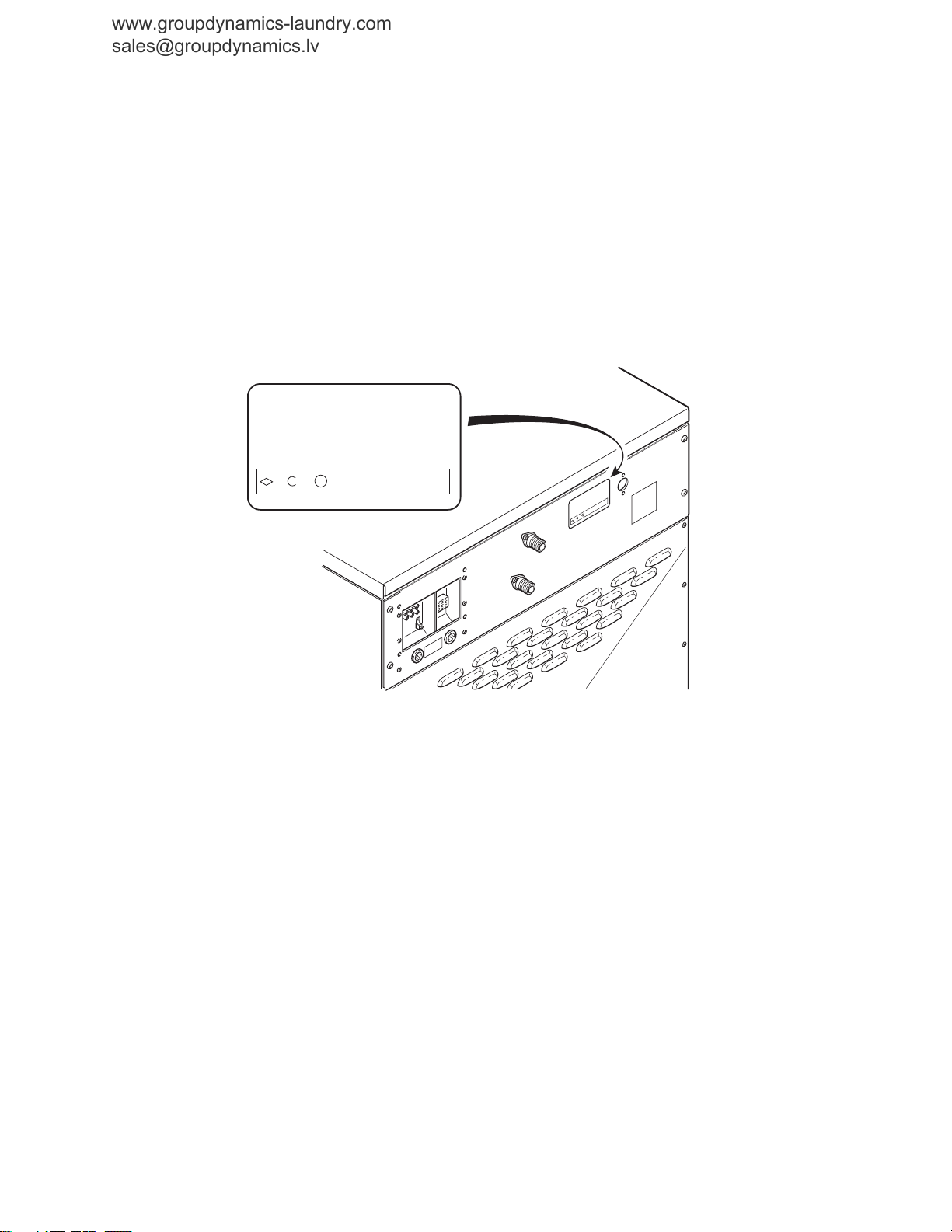
Nameplate Location
When calling or writing about your product, be sure to
mention model and serial numbers. Model and serial
numbers are located on nameplate(s) as shown.
CHM2411P
6
© Copyright, Alliance Laundry Systems LLC – DO NOT COPY or TRANSMIT F232204R5

Model Identification
www.groupdynamics-laundry.com
sales@groupdynamics.lv
Information in this manual is applicable to these washers.
Introduction
DC20NC2
DC25NC2
DC30NC2
DC40NC2
DC60NC2
HC18NC2
HC18NP2
HC20NC2
HC25NC2
HC25NP2
HC27NC2
HC27NP2
HC30NC2
HC35NC2
HC35NP2
HC40NC2
HC50NC2
HC50NP2
HC60NC2
HC60NCF
HC80NCV
NC18NP2
NC27NP2
NC50NP2
NC80NPV
SC18NC2
SC18NP2
SC18NR2
SC18NX2
SC20NC2
SC20NR2
SC20NX2
SC25NC2
SC25NP2
SC25NR2
SC25NX2
SC27NC2
SC27NP2
SC27NR2
SC27NX2
SC30NC2
SC30NR2
SC30NX2
SC35NC2
SC35NP2
SC35NR2
SC35NX2
SC40NC2
SC40NR2
SC40NX2
SC50NC2
SC50NP2
SC50NR2
SC50NX2
SC60NC2
SC60NCF
SC60NR2
SC60NRF
SC60NX2
SC60NXF
SC60NYF
SC80NCV
SC80NPV
SC80NRV
SC80NXV
SC80NYV
F232204R5
© Copyright, Alliance Laundry Systems LLC – DO NOT COPY or TRANSMIT
7

Theory of Operation
www.groupdynamics-laundry.com
sales@groupdynamics.lv
Starting the Machine
The door lock will not allow a cycle to be started until
the door has been closed.
Fill
The operator selects a cycle and starts the machine.
Water enters the machine through water valves that are
controlled by the microcomputer. As water fills the
basket, a column of air is trapped in a pressure bulb
and hose. The air pressure continues to increase as the
basket fills with water. When the desired water level is
reached, the water level switch triggers the
microcomputer and the water valves turn off.
A vacuum breaker installed in the inlet plumbing
prevents the backflow of water.
Supply
The operator can either connect external liquid
supplies to the machine or fill the supply dispenser
with liquid or dry supplies. The supply dispenser's
nozzles flush the compartments with water at the
appropriate times throughout a cycle.
Drain
Cabinet Hardmount washer-extractors use a normally
open gravity-type drain system. No pump is used.
When the drain valve opens, the perforated basket
allows water to drain from it.
In the event of a power failure, the drain valve will
open automatically and the machine will drain.
Extract
A final high-speed extract step removes water from the
load, which maximizes drying efficiency.
The door lock system will not allow the door to be
opened until the cycle has finished.
Wash
The basket includes ribs that lift the laundry from the
wash water. The laundry then tumbles back into the
bath.
In 2-speed and variable-speed models, 1 dual-speed
motor drives the basket's shaft with a V-belt. In 3speed models, 2 motors drive the basket's cylinder
with a V-belt.
18-60 pound capacity models use 2 bearings that are
held in place by a single cast-iron trunnion that is
bolted to the frame. 80 and 125-pound capacity
models use 2 flange-type bearing that are bolted to the
frame.
8
© Copyright, Alliance Laundry Systems LLC – DO NOT COPY or TRANSMIT F232204R5
Troubleshooting
www.groupdynamics-laundry.com
sales@groupdynamics.lv
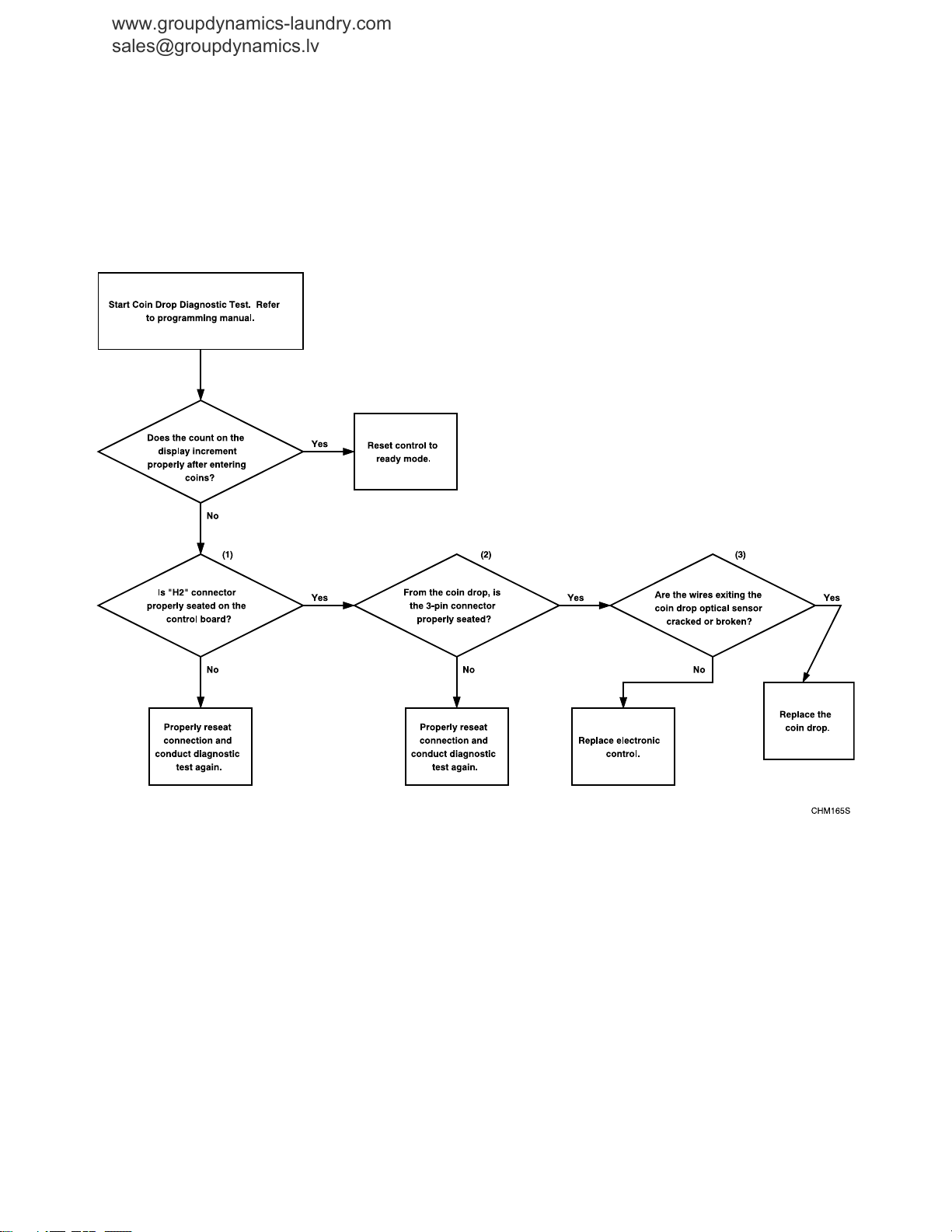
1. Coins Ignored When Entered
F232204R5
© Copyright, Alliance Laundry Systems LLC – DO NOT COPY or TRANSMIT
9
Troubleshooting
www.groupdynamics-laundry.com
sales@groupdynamics.lv
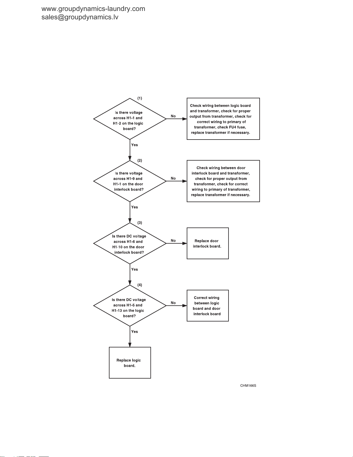
2. Control Has No Display
10
© Copyright, Alliance Laundry Systems LLC – DO NOT COPY or TRANSMIT
F232204R5

Troubleshooting
www.groupdynamics-laundry.com
sales@groupdynamics.lv
Please see following 2 pages for wiring diagram information.
F232204R5
© Copyright, Alliance Laundry Systems LLC – DO NOT COPY or TRANSMIT
11
Troubleshooting
62
48
KA3
AUXILIARY DRAIN
OPTIONAL DRAIN
PUMP RELAY
M4
1
1
LOW
SPEED
HIGH
SPEED
PE
GND
L1
L2
ALL WIRE IS 18 AWG
UNLESS OTHERWISE SPECIFIED
ALL MOTOR CIRCUIT
WIRING IS 14 AWG
1
3
AP1
OUTPUT
BOARD
2
4
5
7
MOTOR COOLING
FAN
DRAIN VALVE
MOTOR
M3
BLUE (WASH)
BLACK (WASH)
WHITE (SPIN)
BLUE (SPIN)
RED (SPIN)
BLACK (SPIN)
WHITE (WASH)
CHASSIS
M1
~
1
6875
L2
L1
FU3
CHASSIS
LIMIT OF
EQUIPMENT
14 AWG(2.5mm )
18 AWG
L1
L2
XT1
XT2
P.E.
M2
KA2 DRAIN
RELAY
FU5 FU6
MECHANICAL
INTERLOCK
MOTOR
THERMAL
PROTECTOR
FU2 FU1
XX
TC1 CONTROL
TRANSFORMER
132
COIN METER
CONFIGURATION
CARD READER
CONFIGURATION
P/N 370433
or 370434
LOGIC BOARD TO OUTPUT BOARD
COMMUNICATION
C2-R
DOOR UNLOCK SOLENOID
YA2
TEMP PROBE
OPTION
(HEAT SAFETY)
LOW LEVEL
HIGH
FU4
YA1
KM5
KM4
KM3
COIN BLOCKING COIL (24VAC)
OPTIONAL
YV9
KA2
YV8
REV CONTACTOR
YV2
FWD CONTACTOR
YV1
OPTIONAL STEAM HEAT
DRAIN VALVE RELAY
YV4
AUXILIARY FILL VALVE
COLD FILL WATER VALVE
YV5
HOT FILL WATER VALVE
YV4
SUPPLY 4
SUPPLY 3 SOFTENER
YV3
SUPPLY 2 WASH
DETERGENT/BLEACH
SUPPLY 1 PREWASH
DETERGENT
DOOR LOCKED
SWITCH
DOOR CLOSED
SWITCH
DOOR REED SWITCH
(MAGNETIC)
POWER "IN"
SPARE
SPARE
ST1
SP1b
+
MACHINE
CONFIG.
5VDC
YV9
COLD FLUSH WATER VALVE
HOT FLUSH WATER VALVE
YV10
SP1c
MEDIUM
SP1a
CHASSIS
ST2
EXTRACT CONTACTOR
CURRENT OVERLOAD RELAY
2
J9-6-2
J9-6-1
J9-6-3
J9-6-4
J9-6-5
J9-6-6
J9-6-8
F5A 250V
24VAC
87
86
82J
84J
T1A
250V
T1A
250V
8482
DV2DV1
24VAC
63
42
3
5
4
6
EMI FILTER
0.001uf Cap.
P/N 270319
C23
6
KM3 FWD WASH
CONTACTOR
KM4 REV WASH
CONTACTOR
KM5 EXTRACT
CONTACTOR
C24
PURPLE
PURPLE
J9-6-9 J9-6-7
80
81
85
79
250V
T1.6A
83
250V
T1.6A
VIO
(16 AWG)
YEL
BRN
BLU
WHT
YEL
ORN
(22 AWG
BLK
30
43N
77C
BRN
YEL
ORG
H2-1
H2-2
H2-3
J3-1-3
J3-1-1
J3-1-2
ACCESS PANEL /
PROGRAM SWITCH
78
76
77A
77B
J11-1-7
J11-1-5
J11-1-1
J11-1-9
J11-1-1
J11-1-3
F3A 250V
BRN
YEL
ORG
H2-1
H2-2
H2-3
H2-10
38
H3-1
H1-7
H1-8
H1-9
TEST
SPARE
5vDC
H1-6
H1-2
H1-1
H3-4
"EMPTY" LEVEL
SWITCH
H3-5
FS-1
F2A
250V
F2A
250V
F2A
250V
F2A
250V
F2A
250V
F2A
250V
F2A
250V
F2A
250V
F2A
250V
F2A
250V
F2A
250V
F2A
250V
250V
F2A
250V
F2A
250V
F2A
250V
F2A
H5-10
H5-11
H5-5
H5-14
H5-13
H5-8
H5-9
H4-3
H4-4
H4-1
H4-5
H4-6
H4-7
H4-8
H5-6
H5-7
H5-12
H5-4
H5-3
H5-1
H5-2
H1-5
H1-10
H1-4
H1-3
H3-6
H3-3
(F16)
(F15)
(F14)
(F13)
(F12)
(F11)
(F10)
(F9)
(F8)
(F7)
(F6)
(F5)
(F4)
(F3)
(F2)
(F1)
(V6)
(V7)
(V8)
(V9)
(V10)
(V11)
(V12)
(V13)
(V14)
(V15)
(V16)
(V17)
(V18)
(V19)
(V20)
(V21)
J9-1-9
C2-B
BLK RED
D1 (ORG)D2 (BLK)
D5
D3
D4
D3
D6
J9-1-5
J9-1-8
J9-1-7
J9-1-6
J9-1-4
J9-1-3
J9-1-2
J9-1-1
42J
42
49
51
53
55
59
61
43
45
60
62
46
47
39
5
16
3
6
4
13
15
14
C1-R
C1-B
17
19
18
40
41
36
37
34
33
32
35
30
31
J3-1-3
J3-1-1
J3-1-2
J9-2-6 J9-2-7
J9-2-2
J9-2-4
J9-2-5
J9-2-3
J9-2-1
H1-8
H1-2
H1-11
H1-5
H1-16
H1-7
H1-12
H1-4
P >
H4-5
H4-1
H4-3
H5-2
H5-1
H8-3
H8-5
H8-6
H8-1
H8-8
H8-7
T
S
COIN VAULT
AUDIT SWITCH
ACCESS PANEL /
PROGRAM SWITCH
V8VN8
V2VN2
VN1 V1
VN4 V4
VN2 V5
V4VN5
VN3 V3
VN1
VN1
65
57
H4-2
20
78
76
77A
63J
77B
FS-3FS-2
VN9 V9
V10VN10
63
H3-2
32
P >
31
22
21
P >
22
21
64
H1-2
H1-1
95
96
1
{
}
{
}
Y: 208-240V/60HZ/1ø/2W/24VAC CTRL
www.groupdynamics-laundry.com
sales@groupdynamics.lv
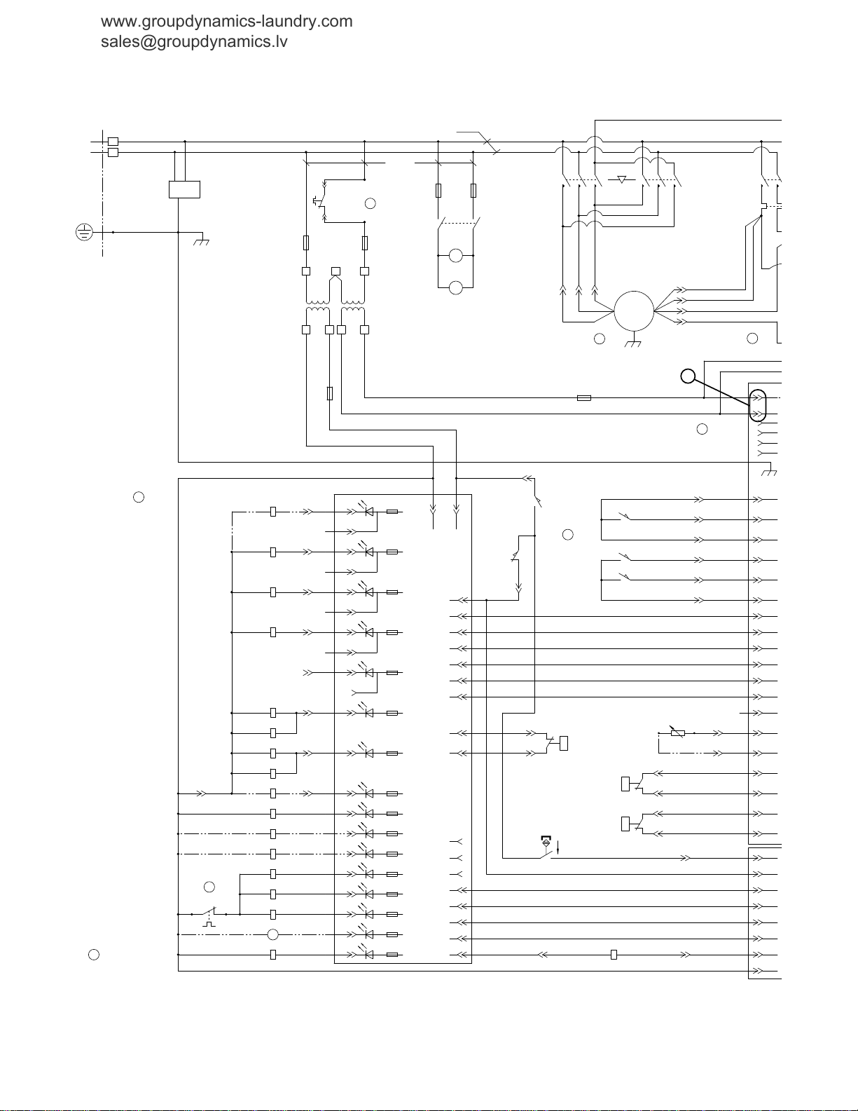
Control Has No Display (Sheet 1 of 2)
NOTE: Refer to the wiring diagram supplied with
your machine.
12
© Copyright, Alliance Laundry Systems LLC – DO NOT COPY or TRANSMIT
F232204R5
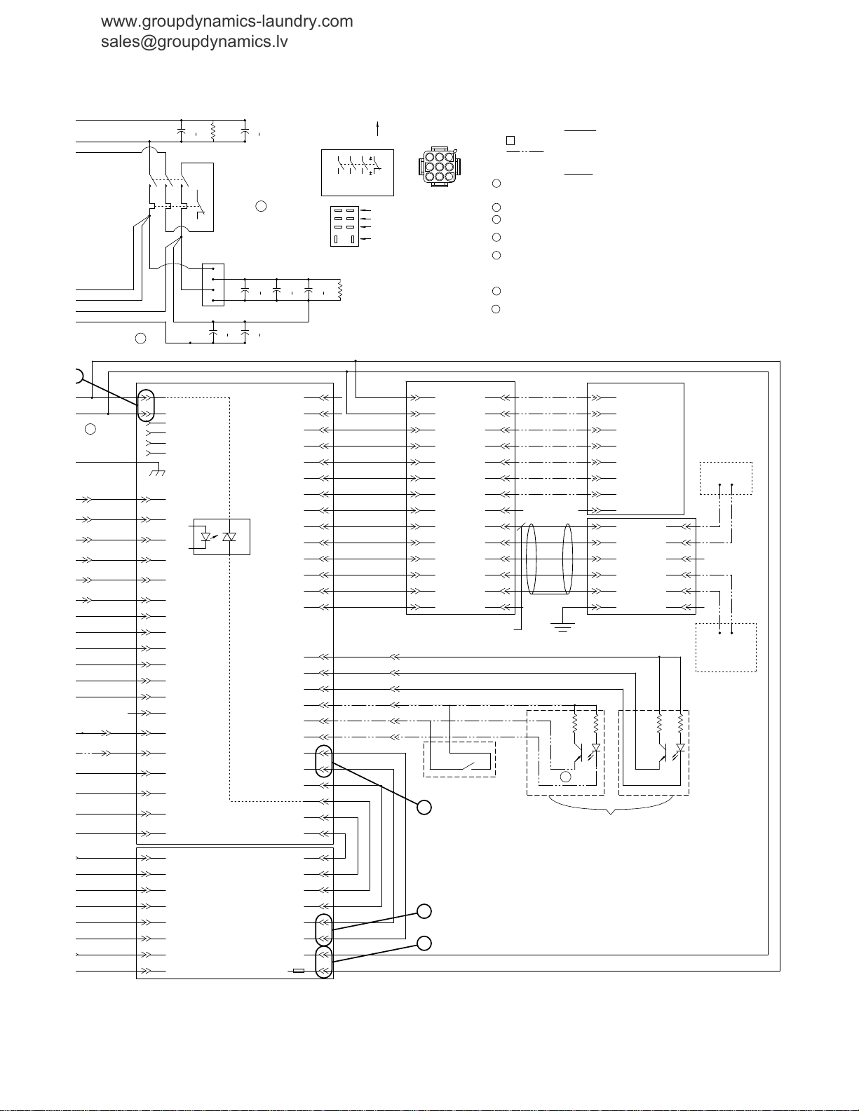
Control Has No Display (Sheet 2 of 2)
H1-1
OPTIONAL SINGLE COIN DROP
(MECHANICAL ACTUATION)
RED
GREEN
NETWORK
INTERFACE
BOARD
NETWORK
BOARD
CARDMATE
PLUS
(OPTIONAL)
1
HIGH
SPEED
NOTES:
LEGEND
7
CONFIGURATION SHOWN IS
FOR ELMO MOTORS ONLY
ALL MOTOR CIRCUIT WIRING
IS 14 AWG
4
DOOR INTERLOCK
CONTROL BOARD
AP3
OPTIONAL DUAL COIN DROP
(OPTICAL ACTUATION)
AP2
CONTROL ASSY
LOGIC BOARD
5
TO NEXT UNIT OR
TERMINATION
RESISTOR IF
FINAL MACHINE
FROM PC OR
PREVIOUS UNIT
P.E.
WHITE (SPIN)
BLUE (SPIN)
RED (SPIN)
BLACK (SPIN)
7
6
MACHINE CONFIG. JUMPER SUMMARY (W/+5VDC PINS H5-8 THRU H5-12):
HS-6 DOMESTIC/INTERNATIONAL: JUMPER-INTERNATIONAL. NO JUMPER-DOMESTIC
HS-5 WATER HEATING: JUMPER-TEMP-CONTROLLED FILL. NO JUMPER-HEAT W/HEATER
HS-4 DRAIN/PUMP: JUMPER-PUMP ONLY. NO JUMPER-DRAIN VALVE PRESENT
HS-3 MOTOR DRIVE: JUMPER-VFD. NO JUMPER-2 SPD
5
COIN BLOCKING COIL, COIN METER AND OPTICAL COIN DROP ACTUATION CIRCUIT WILL NOT
BE PRESENT ON CARD READER VERSIONS OF MACHINES.
- OPTIONAL CONNECTIONS
SUPPLY 1 COMPARTMENT WILL FLUSH WITH EACH FILL WHEN YV3 IS NOT INSTALLED.
2
= TERMINAL STRIP, TERMINAL #8
8
TYPICAL
RELAY
1
IF MOTOR ROTATION IS INCORRECT, REVERSE "BLUE" AND "BLACK" WIRES FOR LOW SPEED
OR "RED" AND "WHITE" WIRES FOR HIGH SPEED. J9-6 MOTOR MAY NOT BE PRESENT ON
ALL MACHINES.
USE CONFIGURATION SHOWN AND REMOVE COIN VAULT AUDIT SWITCH FOR REMOTE START
OR CARD READER MODELS.
3
4
YV9 AND YV10 ARE USED WITH TWO SEPARATE 3 WAY "ELBI" WATER VALVES, ARE NOT
USED WITH MULLER MIXING VALVE.
ST2
CURRENT
OVERLOAD
SOLID
STATE
SWITCH
CONTACTOR DETAIL
CONTACTORS
FACE FRONT
OF MACHINE
J9-6 MOTOR
CONNECTOR
C2-R
COIN DROP 2 (OPT) COIN DROP 1 (STD)
BLUE
GREEN
RED
BLUE
GREEN
RED
1K15K 15K 1K
MACHINE
CONFIG.
5VDC
CHASSIS
NBP
TXD
VUR
RXD
5VDC
H6-14
H6-5
H6-4
H6-3
H6-2
24VDC
H6-1
BLK
RED
BLK
RED
H1-6
H1-5
H1-4
H1-3
H1-2
H1-1
H2-6
H2-5
H2-4
H2-3
H2-2
H2-1
H1-11
H1-13
H1-12
H1-10
H1-3
H1-4
PNK
BLU/WHT
BLU
GRY
H6-6
GRY/YEL
H6-7
NOT USED
H6-8
NOT USED
H6-9
RED/WHT
H6-10
ORG/WHT
H6-11
BLK/WHT
H6-12
BLK/WHT
H6-13
TAN
H1-6
H1-7
H1-3
H1-4
H1-5
H1-12
H1-10
H1-13
H1-14
H1-1
H1-11
H1-2
H1-9
H1-8
H2-1
H2-2
H2-3
H2-4
H2-5
H2-6
H2-7
H2-8
H3-1
H3-2
H3-3
H3-4
H3-5
H3-6
NAG
24VDC
NRFA
5VDC
5VDC
COMM
CRP
COMM
GND
B OUT
A OUT
GND
B IN
A IN
H1-5
5VDC
GND
GND
5VDC
RCV
XMIT
24VDC
(VUR)
GRN/YEL
WHT/BLU
RED/BLU
1
2
4
3
5
6
7
8
NORMALLY CLOSED CONTACTS
NORMALLY OPEN CONTACTS
COMMON
COIL
ODD NUMBERED CONTACTS ARE ISOLATED FROM EVEN
NUMBERED CONTACTS BUT OPERATE SIMULTANEOUSLY.
TERMINAL NUMBERS MAY VARY FROM RELAY TO RELAY
BUT TERMINAL POSITIONS ARE THE SAME.
50uF
SS1
SS3
SS2
2
1
3
4
JMP
JMP
50uF
12K
130uF
20uF
C23
JMP
69
69
12K
95
96
20uF
C20
C21
KM4 REV WASH
CONTACTOR
KM5 EXTRACT
CONTACTOR
JMP
130uF 130uF
JMP
JMP
JMP
JMP
JMP
TYPICAL CONTACTOR MARKINGS.
SUBJECT TO CHANGE.
T3T2T1
L3L2L1
963
852
741
BRN
YEL
ORG
H2-1
H2-2
H2-3
J3-1-3
J3-1-1
J3-1-2
BLK/PNK
WHT/BLK
RED/BLK
BLK
WHITE
RED
CD2 COMM
CD2
CD2 5VDC
CD1 COMM
CD1 5VDC
CD1
BRN
YEL
ORG
H2-1
H2-2
H2-3
H2-10
LOGIC GROUND
H5-8
THRU
H5-12
H5-3
THRU
H5-7
(ACH INPUT)
RETURN/OUTPUT FOR DOOR
LOCK/UNLOCK SOLENOID
C2-B
5
16
3
6
4
13
15
14
C1-R
C1-B
17
19
18
30
31
8
9
12
9
8
1
2
7
10
11
12
10
7
2
1
J3-3-3
J3-3-2
J3-3-1
J3-2-3
J3-2-2
J3-2-1
J3-1-3
J3-1-1
J3-1-2
J9-2-4
J9-2-5
MDC 30XX
24vDC
LOGIC
GROUND
V U R
LOCK/UNLOCK
LOGIC SIGNAL
DOOR LOCKED OUTPUT
DOOR CLOSED OUTPUT
H1-15
H1-14
H1-13
H1-3
H1-6
H1-10
H1-4
H1-5
H1-3
H1-8
H1-11
H1-13
H1-8
LOGIC GROUND
H1-2
24vDC
H1-11
V U R
H1-5
OUTPUT/RETURN FOR DOOR
UNLOCK/LOCK SOLENOID
H1-16
H1-7
AC COMMON INPUT
F2A
250V
ACH 24V
AC COMMON
H1-9
H1-1
H1-12
DOOR LOCKED INPUT
H1-4
DOOR CLOSED INPUT
H4-5
H4-1
H4-3
H5-2
H5-1
LOGIC GROUND
HIGH WATER LEVEL
PRESSURE SWITCH
LOW WATER LEVEL
PRESSURE SWITCH
H8-3
RESET SIGNAL
H8-5
SPISIMO
H8-6
SPICLK
H8-1
SPISOMI
H8-8
"EMPTY" LEVEL
PRESSURE SWITCH
H8-7
LOGIC GROUND
H2-5
H2-4
H2-6
H2-8
H2-7
TEMPERATURE
SENSOR INPUT
H2-9
OUT TO TEMP SENSOR
(ACH INPUT)
H4-2
LOGIC GROUND
20
H1-2
H1-1
SS4
NOT USED
SHIELDED
22 AWG
(DRAIN)
WHT/BLU
BLUE
WHT/ORG
ORANGE
RED/WHT
BLK/WHT
BLK/WHT
RED/WHT
PNK
BLU/WHT
BLU
ST2 (THERMAL OVERLOAD RELAY) MUST BE SET TO "TRIP" AT APPROPRIATE CURRENT
LOAD. SET DIAL TO MOTOR NAMEPLATE FULL LOAD CURRENT RATING. IF MOTOR HAS
SERVICE FACTOR OF LESS THAN 1.15. SET DIAL TO 90% OF NAMEPLATE FULL
LOAD CURRENT RATING. ALSO SET OPERATING MODE DIAL TO "M" (MANUAL RESET)
TO PREVENT ACCIDENTAL STARTING OF MOTOR.
2
CHM167S
3
4
{
}
{
}
www.groupdynamics-laundry.com
sales@groupdynamics.lv
Troubleshooting
© Copyright, Alliance Laundry Systems LLC – DO NOT COPY or TRANSMIT
F232204R5
13
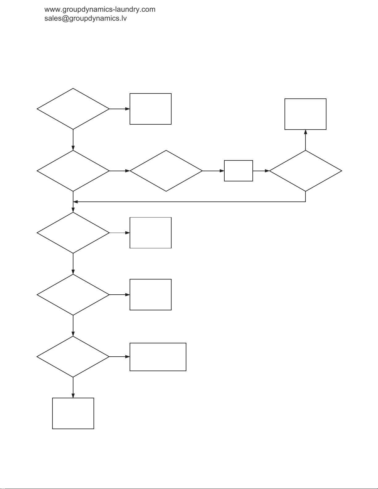
Troubleshooting
Is there voltage
at wire 21 or terminal 31
on pressure switch to wire
19 at H4-1 on the
logic board?
Is
there voltage at
V1 or V2 on the water inlet
valve to FS2 on the
output board?
Is
there voltage from
H5-8 or H5-1 to FS2
on the output
board?
Are
fuses F6 and F7
on the output board
blown?
Are
LEDs V11 and
V12 on the output
board emitting
light (on)?
Check wiring to
pressure switch.
Replace pressure
switch if necessary.
Correct wiring
between water
inlet valve and
output board.
Water fill
operational.
(1)
(2) (3)
(4)
(5)
No
Yes
Note: Everything working
properly and the control
calling for water fill.
No
Yes
Replace the
blown
fuse(s).
Are
LEDs V11 and
V12 on the output
board emitting
light (on)?
Replace output
board.
Replace output
board.
No
YesYes
Yes
No
No
Note: Checking
for voltage across
the water valve.
Yes
Does
the water
inlet valve operate
properly? Does
water enter the
machine?
Make sure water supply
is turned on. Check for
kinks or blockage in the
hoses. Rebuild or replace
the water inlet valve.
Yes
No
CHM457S
www.groupdynamics-laundry.com
sales@groupdynamics.lv
3. No Fill Analysis
14
© Copyright, Alliance Laundry Systems LLC – DO NOT COPY or TRANSMIT
F232204R5

Troubleshooting
www.groupdynamics-laundry.com
sales@groupdynamics.lv
Please see following 2 pages for wiring diagram information.
F232204R5
© Copyright, Alliance Laundry Systems LLC – DO NOT COPY or TRANSMIT
15
Troubleshooting
62
48
KA3
AUXILIARY DRAIN
OPTIONAL DRAIN
PUMP RELAY
M4
1
1
LOW
SPEED
HIGH
SPEED
PE
GND
L1
L2
ALL WIRE IS 18 AWG
UNLESS OTHERWISE SPECIFIED
ALL MOTOR CIRCUIT
WIRING IS 14 AWG
1
3
AP1
OUTPUT
BOARD
2
4
5
7
MOTOR COOLING
FAN
DRAIN VALVE
MOTOR
M3
BLUE (WASH)
BLACK (WASH)
WHITE (SPIN)
BLUE (SPIN)
RED (SPIN)
BLACK (SPIN)
WHITE (WASH)
CHASSIS
M1
~
1
6875
L2
L1
FU3
CHASSIS
LIMIT OF
EQUIPMENT
14 AWG(2.5mm )
18 AWG
L1
L2
XT1
XT2
P.E.
M2
KA2 DRAIN
RELAY
FU5 FU6
MECHANICAL
INTERLOCK
MOTOR
THERMAL
PROTECTOR
FU2 FU1
XX
TC1 CONTROL
TRANSFORMER
132
COIN METER
CONFIGURATION
CARD READER
CONFIGURATION
P/N 370433
or 370434
LOGIC BOARD TO OUTPUT BOARD
COMMUNICATION
C2-R
DOOR UNLOCK SOLENOID
YA2
TEMP PROBE
OPTION
(HEAT SAFETY)
LOW LEVEL
HIGH
FU4
YA1
KM5
KM4
KM3
COIN BLOCKING COIL (24VAC)
OPTIONAL
YV9
KA2
YV8
REV CONTACTOR
YV2
FWD CONTACTOR
YV1
OPTIONAL STEAM HEAT
DRAIN VALVE RELAY
YV4
AUXILIARY FILL VALVE
COLD FILL WATER VALVE
YV5
HOT FILL WATER VALVE
YV4
SUPPLY 4
SUPPLY 3 SOFTENER
YV3
SUPPLY 2 WASH
DETERGENT/BLEACH
SUPPLY 1 PREWASH
DETERGENT
DOOR LOCKED
SWITCH
DOOR CLOSED
SWITCH
DOOR REED SWITCH
(MAGNETIC)
POWER "IN"
SPARE
SPARE
ST1
SP1b
+
MACHINE
CONFIG.
5VDC
YV9
COLD FLUSH WATER VALVE
HOT FLUSH WATER VALVE
YV10
SP1c
MEDIUM
SP1a
CHASSIS
ST2
EXTRACT CONTACTOR
CURRENT OVERLOAD RELAY
2
J9-6-2
J9-6-1
J9-6-3
J9-6-4
J9-6-5
J9-6-6
J9-6-8
F5A 250V
24VAC
87
86
82J
84J
T1A
250V
T1A
250V
8482
DV2DV1
24VAC
63
42
3
5
4
6
EMI FILTER
0.001uf Cap.
P/N 270319
C2
KM3 FWD WASH
CONTACTOR
KM4 REV WASH
CONTACTOR
KM5 EXTRACT
CONTACTOR
C24
PURPLE
PURPLE
J9-6-9 J9-6-7
80
81
85
79
250V
T1.6A
83
250V
T1.6A
VIO
(16 AWG)
YEL
BRN
BLU
WHT
YEL
ORN
(22 AWG
BLK
30
43N
77C
BRN
YEL
ORG
H2-1
H2-2
H2-3
J3-1-3
J3-1-1
J3-1-2
ACCESS PANEL /
PROGRAM SWITCH
78
76
77A
77B
J11-1-7
J11-1-5
J11-1-1
J11-1-9
J11-1-1
J11-1-3
F3A 250V
BRN
YEL
ORG
H2-1
H2-2
H2-3
H2-10
38
H3-1
H1-7
H1-8
H1-9
TEST
SPARE
5vDC
H1-6
H1-2
H1-1
H3-4
"EMPTY" LEVEL
SWITCH
H3-5
FS-1
F2A
250V
F2A
250V
F2A
250V
F2A
250V
F2A
250V
F2A
250V
F2A
250V
F2A
250V
F2A
250V
F2A
250V
F2A
250V
F2A
250V
250V
F2A
250V
F2A
250V
F2A
250V
F2A
H5-10
H5-11
H5-5
H5-14
H5-13
H5-8
H5-9
H4-3
H4-4
H4-1
H4-5
H4-6
H4-7
H4-8
H5-6
H5-7
H5-12
H5-4
H5-3
H5-1
H5-2
H1-5
H1-10
H1-4
H1-3
H3-6
H3-3
(F16)
(F15)
(F14)
(F13)
(F12)
(F11)
(F10)
(F9)
(F8)
(F7)
(F6)
(F5)
(F4)
(F3)
(F2)
(F1)
(V6)
(V7)
(V8)
(V9)
(V10)
(V11)
(V12)
(V13)
(V14)
(V15)
(V16)
(V17)
(V18)
(V19)
(V20)
(V21)
J9-1-9
C2-B
BLK RED
D1 (ORG)D2 (BLK)
D5
D3
D4
D3
D6
J9-1-5
J9-1-8
J9-1-7
J9-1-6
J9-1-4
J9-1-3
J9-1-2
J9-1-1
42J
42
49
51
53
55
59
61
43
45
60
62
46
47
39
5
16
3
6
4
13
15
14
C1-R
C1-B
17
19
18
40
41
36
37
34
33
32
35
30
31
J3-1-3
J3-1-1
J3-1-2
J9-2-6 J9-2-7
J9-2-2
J9-2-4
J9-2-5
J9-2-3
J9-2-1
H1-8
H1-2
H1-11
H1-5
H1-16
H1-7
H1-12
H1-4
P >
H4-5
H4-1
H4-3
H5-2
H5-1
H8-3
H8-5
H8-6
H8-1
H8-8
H8-7
COIN VAULT
AUDIT SWITCH
ACCESS PANEL /
PROGRAM SWITCH
V8VN8
V2VN2
VN1 V1
VN4 V4
VN2 V5
V4VN5
VN3 V3
VN1
VN1
65
57
H4-2
20
78
76
77A
63J
77B
FS-3FS-2
VN9 V9
V10VN10
63
H3-2
32
P >
31
22
21
P >
22
21
64
H1-2
H1-1
95
96
1
5 4
2
3
{
{
Y: 208-240V/60HZ/1ø/2W/24VAC CTRL
www.groupdynamics-laundry.com
sales@groupdynamics.lv
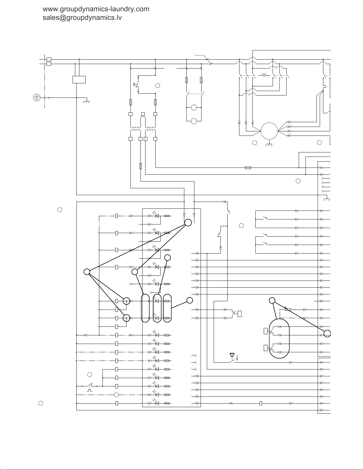
No Fill Analysis (Sheet 1 of 2)
NOTE: Refer to the wiring diagram supplied with
your machine.
16
© Copyright, Alliance Laundry Systems LLC – DO NOT COPY or TRANSMIT
F232204R5
No Fill Analysis (Sheet 2 of 2)
H1-1
OPTIONAL SINGLE COIN DROP
(MECHANICAL ACTUATION)
RED
GREEN
NETWORK
INTERFACE
BOARD
NETWORK
BOARD
CARDMATE
PLUS
(OPTIONAL)
1
HIGH
SPEED
NOTES:
LEGEND
7
CONFIGURATION SHOWN IS
FOR ELMO MOTORS ONLY
ALL MOTOR CIRCUIT WIRING
IS 14 AWG
4
DOOR INTERLOCK
CONTROL BOARD
AP3
OPTIONAL DUAL COIN DROP
(OPTICAL ACTUATION)
AP2
CONTROL ASSY
LOGIC BOARD
5
TO NEXT UNIT OR
TERMINATION
RESISTOR IF
FINAL MACHINE
FROM PC OR
PREVIOUS UNIT
P.E.
WHITE (SPIN)
BLUE (SPIN)
RED (SPIN)
BLACK (SPIN)
7
6
MACHINE CONFIG. JUMPER SUMMARY (W/+5VDC PINS H5-8 THRU H5-12):
HS-6 DOMESTIC/INTERNATIONAL: JUMPER-INTERNATIONAL. NO JUMPER-DOMESTIC
HS-5 WATER HEATING: JUMPER-TEMP-CONTROLLED FILL. NO JUMPER-HEAT W/HEATER
HS-4 DRAIN/PUMP: JUMPER-PUMP ONLY. NO JUMPER-DRAIN VALVE PRESENT
HS-3 MOTOR DRIVE: JUMPER-VFD. NO JUMPER-2 SPD
5
COIN BLOCKING COIL, COIN METER AND OPTICAL COIN DROP ACTUATION CIRCUIT WILL NOT
BE PRESENT ON CARD READER VERSIONS OF MACHINES.
- OPTIONAL CONNECTIONS
SUPPLY 1 COMPARTMENT WILL FLUSH WITH EACH FILL WHEN YV3 IS NOT INSTALLED.
2
= TERMINAL STRIP, TERMINAL #8
8
TYPICAL
RELAY
1
IF MOTOR ROTATION IS INCORRECT, REVERSE "BLUE" AND "BLACK" WIRES FOR LOW SPEED
OR "RED" AND "WHITE" WIRES FOR HIGH SPEED. J9-6 MOTOR MAY NOT BE PRESENT ON
ALL MACHINES.
USE CONFIGURATION SHOWN AND REMOVE COIN VAULT AUDIT SWITCH FOR REMOTE START
OR CARD READER MODELS.
3
4
YV9 AND YV10 ARE USED WITH TWO SEPARATE 3 WAY "ELBI" WATER VALVES, ARE NOT
USED WITH MULLER MIXING VALVE.
ST2
CURRENT
OVERLOAD
SOLID
STATE
SWITCH
CONTACTOR DETAIL
CONTACTORS
FACE FRONT
OF MACHINE
J9-6 MOTOR
CONNECTOR
C2-R
COIN DROP 2 (OPT) COIN DROP 1 (STD)
BLUE
GREEN
RED
BLUE
GREEN
RED
1K15K 15K 1K
MACHINE
CONFIG.
5VDC
CHASSIS
NBP
TXD
VUR
RXD
5VDC
H6-14
H6-5
H6-4
H6-3
H6-2
24VDC
H6-1
BLK
RED
BLK
RED
H1-6
H1-5
H1-4
H1-3
H1-2
H1-1
H2-6
H2-5
H2-4
H2-3
H2-2
H2-1
H1-11
H1-13
H1-12
H1-10
H1-3
H1-4
PNK
BLU/WHT
BLU
GRY
H6-6
GRY/YEL
H6-7
NOT USED
H6-8
NOT USED
H6-9
RED/WHT
H6-10
ORG/WHT
H6-11
BLK/WHT
H6-12
BLK/WHT
H6-13
TAN
H1-6
H1-7
H1-3
H1-4
H1-5
H1-12
H1-10
H1-13
H1-14
H1-1
H1-11
H1-2
H1-9
H1-8
H2-1
H2-2
H2-3
H2-4
H2-5
H2-6
H2-7
H2-8
H3-1
H3-2
H3-3
H3-4
H3-5
H3-6
NAG
24VDC
NRFA
5VDC
5VDC
COMM
CRP
COMM
GND
B OUT
A OUT
GND
B IN
A IN
H1-5
5VDC
GND
GND
5VDC
RCV
XMIT
24VDC
(VUR)
GRN/YEL
WHT/BLU
RED/BLU
-6-4
-6-5
-6-6
-6-8
1
2
4
3
5
6
7
8
NORMALLY CLOSED CONTACTS
NORMALLY OPEN CONTACTS
COMMON
COIL
ODD NUMBERED CONTACTS ARE ISOLATED FROM EVEN
NUMBERED CONTACTS BUT OPERATE SIMULTANEOUSLY.
TERMINAL NUMBERS MAY VARY FROM RELAY TO RELAY
BUT TERMINAL POSITIONS ARE THE SAME.
50uF
SS1
SS3
SS2
2
1
3
4
JMP
JMP
50uF
12K
130uF
20uF
C23
JMP
69
69
12K
95
96
20uF
C20
C21
KM4 REV WASH
CONTACTOR
KM5 EXTRACT
CONTACTOR
JMP
130uF 130uF
JMP
JMP
JMP
JMP
JMP
TYPICAL CONTACTOR MARKINGS.
SUBJECT TO CHANGE.
T3T2T1
L3L2L1
963
852
741
BRN
YEL
ORG
H2-1
H2-2
H2-3
J3-1-3
J3-1-1
J3-1-2
BLK/PNK
WHT/BLK
RED/BLK
BLK
WHITE
RED
CD2 COMM
CD2
CD2 5VDC
CD1 COMM
CD1 5VDC
CD1
BRN
YEL
ORG
H2-1
H2-2
H2-3
H2-10
LOGIC GROUND
H5-8
THRU
H5-12
H5-3
THRU
H5-7
(ACH INPUT)
RETURN/OUTPUT FOR DOOR
LOCK/UNLOCK SOLENOID
C2-B
5
16
3
6
4
13
15
14
C1-R
C1-B
17
19
18
30
31
8
9
12
9
8
1
2
7
10
11
12
10
7
2
1
J3-3-3
J3-3-2
J3-3-1
J3-2-3
J3-2-2
J3-2-1
J3-1-3
J3-1-1
J3-1-2
J9-2-4
J9-2-5
MDC 30XX
24vDC
LOGIC
GROUND
V U R
LOCK/UNLOCK
LOGIC SIGNAL
DOOR LOCKED OUTPUT
DOOR CLOSED OUTPUT
H1-15
H1-14
H1-13
H1-3
H1-6
H1-10
H1-4
H1-5
H1-3
H1-8
H1-11
H1-13
H1-8
LOGIC GROUND
H1-2
24vDC
H1-11
V U R
H1-5
OUTPUT/RETURN FOR DOOR
UNLOCK/LOCK SOLENOID
H1-16
H1-7
AC COMMON INPUT
F2A
250V
ACH 24V
AC COMMON
H1-9
H1-1
H1-12
DOOR LOCKED INPUT
H1-4
DOOR CLOSED INPUT
H4-5
H4-1
H4-3
H5-2
H5-1
LOGIC GROUND
HIGH WATER LEVEL
PRESSURE SWITCH
LOW WATER LEVEL
PRESSURE SWITCH
H8-3
RESET SIGNAL
H8-5
SPISIMO
H8-6
SPICLK
H8-1
SPISOMI
H8-8
"EMPTY" LEVEL
PRESSURE SWITCH
H8-7
LOGIC GROUND
H2-5
H2-4
H2-6
H2-8
H2-7
TEMPERATURE
SENSOR INPUT
H2-9
OUT TO TEMP SENSOR
(ACH INPUT)
H4-2
LOGIC GROUND
20
H1-2
H1-1
SS4
NOT USED
SHIELDED
22 AWG
(DRAIN)
WHT/BLU
BLUE
WHT/ORG
ORANGE
RED/WHT
BLK/WHT
BLK/WHT
RED/WHT
PNK
BLU/WHT
BLU
ST2 (THERMAL OVERLOAD RELAY) MUST BE SET TO "TRIP" AT APPROPRIATE CURRENT
LOAD. SET DIAL TO MOTOR NAMEPLATE FULL LOAD CURRENT RATING. IF MOTOR HAS
SERVICE FACTOR OF LESS THAN 1.15. SET DIAL TO 90% OF NAMEPLATE FULL
LOAD CURRENT RATING. ALSO SET OPERATING MODE DIAL TO "M" (MANUAL RESET)
TO PREVENT ACCIDENTAL STARTING OF MOTOR.
CHM169S
{
}
{
}
www.groupdynamics-laundry.com
sales@groupdynamics.lv
Troubleshooting
© Copyright, Alliance Laundry Systems LLC – DO NOT COPY or TRANSMIT
F232204R5
17
Troubleshooting
www.groupdynamics-laundry.com
sales@groupdynamics.lv
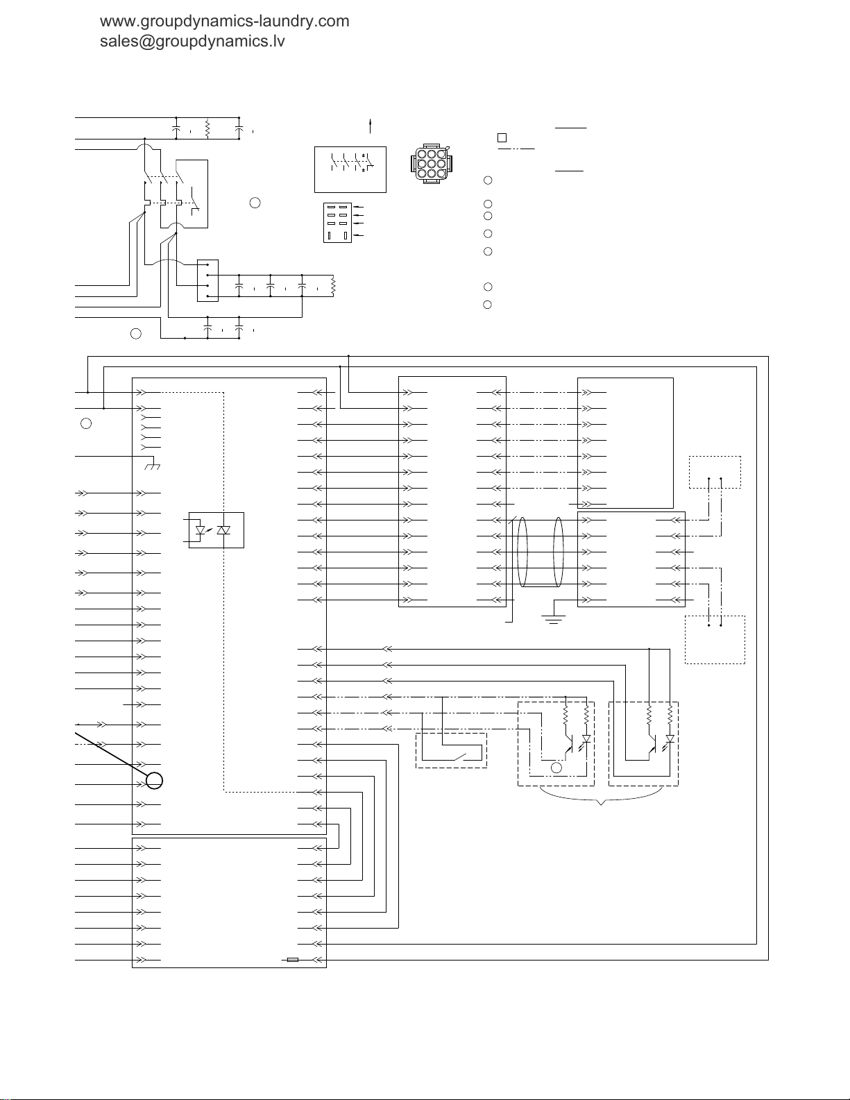
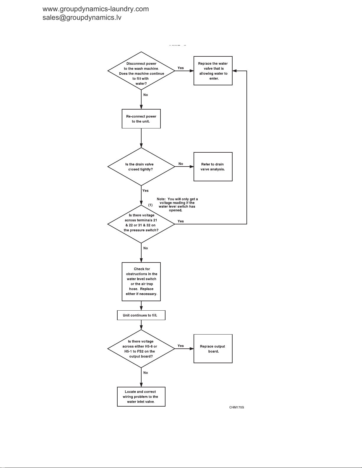
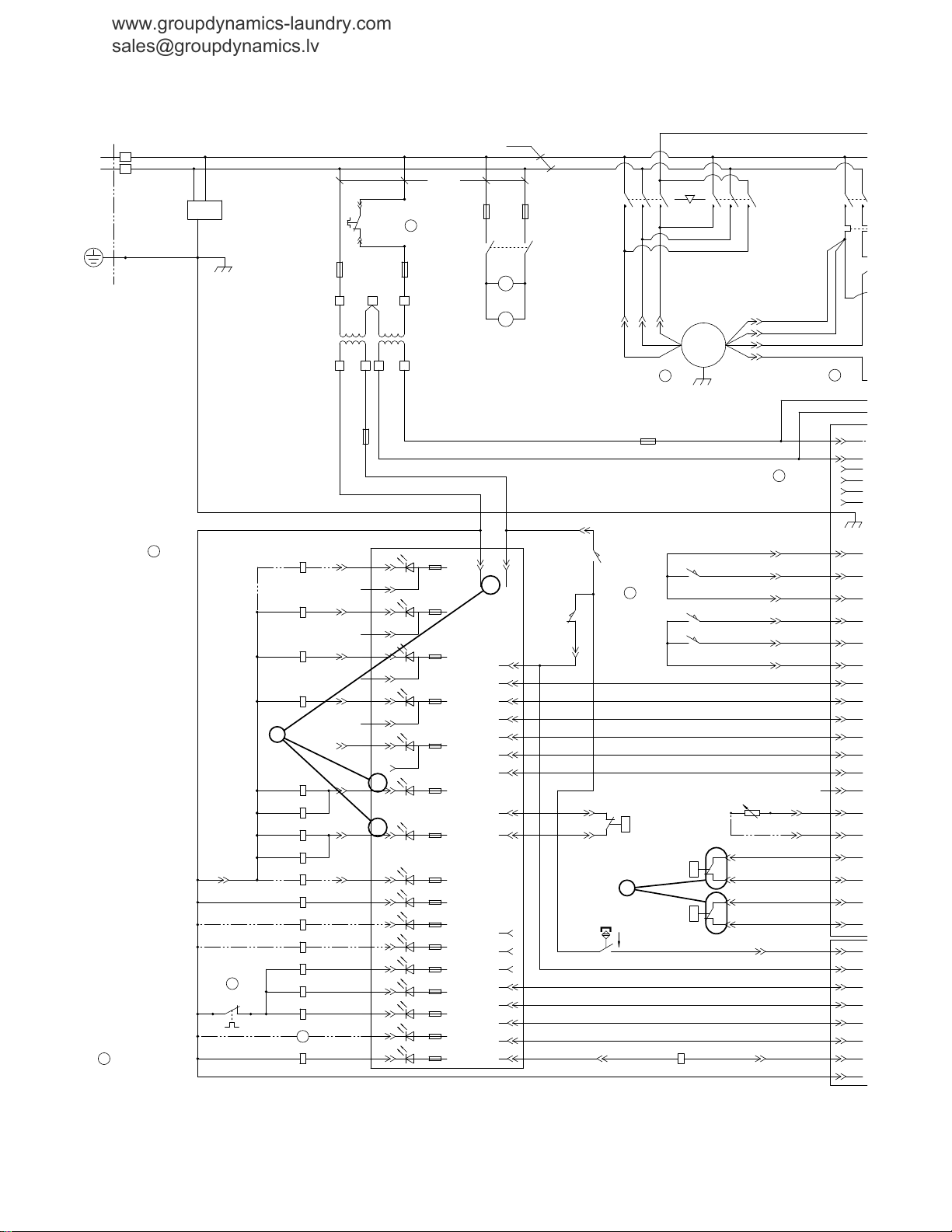
4. Over Flow Analysis
18
© Copyright, Alliance Laundry Systems LLC – DO NOT COPY or TRANSMIT
F232204R5

Troubleshooting
www.groupdynamics-laundry.com
sales@groupdynamics.lv
Please see following 2 pages for wiring diagram information.
F232204R5
© Copyright, Alliance Laundry Systems LLC – DO NOT COPY or TRANSMIT
19
Troubleshooting
62
48
KA3
AUXILIARY DRAIN
OPTIONAL DRAIN
PUMP RELAY
M4
1
1
LOW
SPEED
HIGH
SPEED
PE
GND
L1
L2
ALL WIRE IS 18 AWG
UNLESS OTHERWISE SPECIFIED
ALL MOTOR CIRCUIT
WIRING IS 14 AWG
1
3
AP1
OUTPUT
BOARD
2
4
5
7
MOTOR COOLING
FAN
DRAIN VALVE
MOTOR
M3
BLUE (WASH)
BLACK (WASH)
WHITE (SPIN)
BLUE (SPIN)
RED (SPIN)
BLACK (SPIN)
WHITE (WASH)
CHASSIS
M1
~
1
6875
L2
L1
FU3
CHASSIS
LIMIT OF
EQUIPMENT
14 AWG(2.5mm )
18 AWG
L1
L2
XT1
XT2
P.E.
M2
KA2 DRAIN
RELAY
FU5 FU6
MECHANICAL
INTERLOCK
MOTOR
THERMAL
PROTECTOR
FU2 FU1
XX
TC1 CONTROL
TRANSFORMER
132
COIN METER
CONFIGURATION
CARD READER
CONFIGURATION
P/N 370433
or 370434
LOGIC BOARD TO OUTPUT BOARD
COMMUNICATION
C2-R
DOOR UNLOCK SOLENOID
YA2
TEMP PROBE
OPTION
(HEAT SAFETY)
LOW LEVEL
HIGH
FU4
YA1
KM5
KM4
KM3
COIN BLOCKING COIL (24VAC)
OPTIONAL
YV9
KA2
YV8
REV CONTACTOR
YV2
FWD CONTACTOR
YV1
OPTIONAL STEAM HEAT
DRAIN VALVE RELAY
YV4
AUXILIARY FILL VALVE
COLD FILL WATER VALVE
YV5
HOT FILL WATER VALVE
YV4
SUPPLY 4
SUPPLY 3 SOFTENER
YV3
SUPPLY 2 WASH
DETERGENT/BLEACH
SUPPLY 1 PREWASH
DETERGENT
DOOR LOCKED
SWITCH
DOOR CLOSED
SWITCH
DOOR REED SWITCH
(MAGNETIC)
POWER "IN"
SPARE
SPARE
ST1
SP1b
+
MACHINE
CONFIG.
5VDC
YV9
COLD FLUSH WATER VALVE
HOT FLUSH WATER VALVE
YV10
SP1c
MEDIUM
SP1a
CHASSIS
ST2
EXTRACT CONTACTOR
CURRENT OVERLOAD RELAY
2
J9-6-2
J9-6-1
J9-6-3
J9-6-4
J9-6-5
J9-6-6
J9-6-8
F5A 250V
24VAC
87
86
82J
84J
T1A
250V
T1A
250V
8482
DV2DV1
24VAC
63
42
3
5
4
6
EMI FILTER
0.001uf Cap.
P/N 270319
C23
6
KM3 FWD WASH
CONTACTOR
KM4 REV WASH
CONTACTOR
KM5 EXTRACT
CONTACTOR
C24
PURPLE
PURPLE
J9-6-9 J9-6-7
80
81
85
79
250V
T1.6A
83
250V
T1.6A
VIO
(16 AWG)
YEL
BRN
BLU
WHT
YEL
ORN
(22 AWG
BLK
30
43N
77C
BRN
YEL
ORG
H2-1
H2-2
H2-3
J3-1-3
J3-1-1
J3-1-2
ACCESS PANEL /
PROGRAM SWITCH
78
76
77A
77B
J11-1-7
J11-1-5
J11-1-1
J11-1-9
J11-1-1
J11-1-3
F3A 250V
BRN
YEL
ORG
H2-1
H2-2
H2-3
H2-10
38
H3-1
H1-7
H1-8
H1-9
TEST
SPARE
5vDC
H1-6
H1-2
H1-1
H3-4
"EMPTY" LEVEL
SWITCH
H3-5
FS-1
F2A
250V
F2A
250V
F2A
250V
F2A
250V
F2A
250V
F2A
250V
F2A
250V
F2A
250V
F2A
250V
F2A
250V
F2A
250V
F2A
250V
250V
F2A
250V
F2A
250V
F2A
250V
F2A
H5-10
H5-11
H5-5
H5-14
H5-13
H5-8
H5-9
H4-3
H4-4
H4-1
H4-5
H4-6
H4-7
H4-8
H5-6
H5-7
H5-12
H5-4
H5-3
H5-1
H5-2
H1-5
H1-10
H1-4
H1-3
H3-6
H3-3
(F16)
(F15)
(F14)
(F13)
(F12)
(F11)
(F10)
(F9)
(F8)
(F7)
(F6)
(F5)
(F4)
(F3)
(F2)
(F1)
(V6)
(V7)
(V8)
(V9)
(V10)
(V11)
(V12)
(V13)
(V14)
(V15)
(V16)
(V17)
(V18)
(V19)
(V20)
(V21)
J9-1-9
C2-B
BLK RED
D1 (ORG)D2 (BLK)
D5
D3
D4
D3
D6
J9-1-5
J9-1-8
J9-1-7
J9-1-6
J9-1-4
J9-1-3
J9-1-2
J9-1-1
42J
42
49
51
53
55
59
61
43
45
60
62
46
47
39
5
16
3
6
4
13
15
14
C1-R
C1-B
17
19
18
40
41
36
37
34
33
32
35
30
31
J3-1-3
J3-1-1
J3-1-2
J9-2-6 J9-2-7
J9-2-2
J9-2-4
J9-2-5
J9-2-3
J9-2-1
H1-8
H1-2
H1-11
H1-5
H1-16
H1-7
H1-12
H1-4
P >
H4-5
H4-1
H4-3
H5-2
H5-1
H8-3
H8-5
H8-6
H8-1
H8-8
H8-7
COIN VAULT
AUDIT SWITCH
ACCESS PANEL /
PROGRAM SWITCH
V8VN8
V2VN2
VN1 V1
VN4 V4
VN2 V5
V4VN5
VN3 V3
VN1
VN1
65
57
H4-2
20
78
76
77A
63J
77B
FS-3FS-2
VN9 V9
V10VN10
63
H3-2
32
P >
31
22
21
P >
22
21
64
H1-2
H1-1
95
96
1
2
{
}
{
}
Y: 208-240V/60HZ/1ø/2W/24VAC CTRL
www.groupdynamics-laundry.com
sales@groupdynamics.lv
Over Flow Analysis (Sheet 1 of 2)
NOTE: Refer to the wiring diagram supplied with
your machine.
20
© Copyright, Alliance Laundry Systems LLC – DO NOT COPY or TRANSMIT
F232204R5
 Loading...