

Alliance Laundry Systems HC18MN2, HC18MD2, HC18MH2, HC18MV2, HC18MC2 Troubleshooting Manual
...
Washer-Extractor
Cabinet Hardmount
Mechanical Timer
Refer to Page 8 for Model Numbers
Troubleshooting
www.comlaundry.com
CHM1624C
Part No. F232202R2
December 2006


Table of
Contents
Safety Information...................................................................................3
General Safety Precautions....................................................................3
Important Safety Instructions ................................................................4
Locating an Authorized Servicer...........................................................6
Introduction..............................................................................................7
Customer Service...................................................................................7
Nameplate Location...............................................................................7
Model Identification..............................................................................8
Troubleshooting.......................................................................................9
1. No Hot Fill Analysis (OPL)........................................................10
2. No Hot Fill Analysis (Coin)........................................................14
3. No Cold Fill Analysis (OPL)......................................................18
4. No Cold Fill Analysis (Coin)......................................................22
5. No Supply 2 Fill Analysis (OPL)................................................26
6. No Supply 2 Fill Analysis (Coin) ...............................................30
7. No Supply 3 Fill Analysis (OPL)................................................34
8. No Supply 3 Fill Analysis (Coin) ...............................................38
9. No Motor Function (OPL; Fw and Rev).....................................42
10. No Motor Function (Coin; Fw and Rev).....................................46
11. No Motor Function (OPL; Extract).............................................52
12. No Motor Function (Coin; Extract) ............................................56
13. No Fill at Any Time During the Cycle (OPL)............................62
14. No Fill at Any Time During the Cycle (Coin)............................66
15. Drain Valve Malfunction (OPL).................................................70
16. Drain Valve Malfunction (Coin).................................................74
17. Door Unlocking Malfunction (OPL)...........................................78
18. Door Unlocking Malfunction (Coin)..........................................82
19. Water Running Continuously with Machine Power Off.............86
20. Excessive Vibration and/or Noise During Spin..........................88
21. Excessive Cycle Time.................................................................89
22. Machine Timer Won’t Advance with Door Locked (OPL)........90
23. Machine Timer Won’t Advance with Door Locked (Coin)........94
24. Timer Advances But Machine Does Not Start with Door Locked
(OPL) ..........................................................................................98
25. Timer Advances But Machine Does Not Start with Door Locked
(Coin) ........................................................................................102
26. Overload Relay Tripping Repeatedly .......................................106
27. Compartment 2 of Supply Dispenser Not Flushing
Completely................................................................................107
28. Troubleshooting and Cleaning the Coin Drop..........................108
© Copyright 2006, Alliance Laundry Systems LLC
All rights reserved. No part of the contents of this book may be reproduced or transmitted in any form or by any means without
the expressed written consent of the publisher.
F232202 1
© Copyright, Alliance Laundry Systems LLC – DO NOT COPY or TRANSMIT

Notes
2 F232202
© Copyright, Alliance Laundry Systems LLC – DO NOT COPY or TRANSMIT
Section 1
Safety Information
Throughout this manual and on machine decals, you will find precautionary statements (“CAUTION,”
“WARNING,” and “DANGER”) followed by specific instructions. These precautions are intended for the personal
safety of the operator, user, servicer and those maintaining the machine.
a DANGER
Danger indicates the presence of a hazard that will cause severe personal injury, death or substantial property
damage if the danger is ignored.
a WARNING
Warning indicates the presence of a hazard that can cause severe personal injury, death or substantial property
damage if the warning is ignored.
a CAUTION
Caution indicates the presence of a hazard that will or can cause minor personal injury or property damage if the
caution is ignored.
Additional precautionary statements (“IMPORTANT” and “NOTE”) are followed by specific instructions.
IMPORTANT
The word “IMPORTANT” is used to inform the reader of specific procedures where minor machine damage will
occur if the procedure is not followed.
NOTE
The word “NOTE” is used to communicate installation, operation, maintenance or servicing information that is
important but not hazard related.
General Safety Precautions
In the interest of safety, some general precautions relating to the operation of this machine follow.
WARNING
• Failure to install, maintain and/or operate this product according to the manufacturer’s
instructions may result in conditions which can produce serious injury, death and/or property
damage.
• Do not repair or replace any part of the product or attempt any servicing unless specifically
recommended or published in this Service Manual and unless you understand and have the
skills to carry out the servicing.
• Whenever ground wires are removed during servicing, these ground wires must be
reconnected to ensure that the product is properly grounded and to reduce the risk of fire,
electric shock, serious injury or death.
W006R2
F232202 3
© Copyright, Alliance Laundry Systems LLC – DO NOT COPY or TRANSMIT
(continued)
Safety Information
WARNING
To reduce the risk of electric shock, fire, explosion, serious injury or death:
• Disconnect electric power to the washer-extractor before servicing.
• Never start the washer-extractor with any guards/panels removed.
• Whenever ground wires are removed during servicing, these ground wires must be
reconnected to ensure that the washer-extractor is properly grounded.
WARNING
Repairs that are made to your products by unqualified persons can result in hazards due to
improper assembly or adjustments subjecting you or the inexperienced person making such
repairs to the risk of serious injury, electrical shock or death.
WARNING
If you or an unqualified person perform service on your product, you must assume the
responsibility for any personal injury or property damage which may result. The manufacturer
will not be responsible for any injury or property damage arising from improper service and/or
service procedures.
W460
W007
W008
Always contact your dealer, distributor, service agent or the manufacturer about any problems or conditions you do
not understand.
Important Safety Instructions
WARNING
To reduce the risk of fire, electric shock, serious injury or death to persons when using your
washer, follow these basic precautions:
1. Read all instructions before using the washer-extractor.
2. Refer to the GROUNDING INSTRUCTIONS in the INSTALLATION manual (supplied with your washerextractor) for the proper grounding of the washer-extractor.
3. Do not wash textiles that have been previously cleaned in, washed in, soaked in or spotted with gasoline, drycleaning solvents or other flammable or explosive substances. They give off vapors that could ignite or
explode.
4. Do not add gasoline, dry-cleaning solvents or other flammable or explosive substances to the wash water.
These substances give off vapors that could ignite or explode.
5. Under certain conditions, hydrogen gas may be produced in a hot water system that has not been used for two
weeks or more. HYDROGEN GAS IS EXPLOSIVE. If the hot water system has not been used for such a
period, before using a washer-extractor, turn on all hot water faucets and let the water flow from each for
several minutes. This will release any accumulated hydrogen gas. The gas is flammable. Do not smoke or use
an open flame during this time.
W023E
4 F232202
© Copyright, Alliance Laundry Systems LLC – DO NOT COPY or TRANSMIT

Safety Information
6. Do not allow children to play on or in a washer-extractor. Close supervision of children is necessary when the
washer-extractor is used near children.
7. Before the washer-extractor is removed from service or discarded, remove the door to the washing
compartment.
8. Do not reach into the washer-extractor if the wash basket is moving.
9. Do not install or store the washer-extractor where it will be exposed to water and/or weather.
10. Do not tamper with the washer-extractor’s controls.
11. Do not repair or replace any part of the washer-extractor or attempt any servicing unless specifically
recommended in the user-maintenance instructions or in published user-repair instructions that the user
understands and has the skills to carry out.
12. To reduce the risk of an electrical shock or fire, DO NOT use an extension cord or an adapter to connect the
washer-extractor to an electrical power source.
13. Use the washer-extractor only for its intended purpose, washing clothes.
14. ALWAYS disconnect the washer-extractor from its electrical supply before attempting any service.
15. Install the washer-extractor according to the INSTALLATION INSTRUCTIONS. All connections for water,
drain, electrical power and grounding must comply with local codes and, when required, be made by licensed
personnel.
16. To reduce the risk of fire, textiles which have traces of any flammable substances such as vegetable oil,
cooking oil, machine oil, flammable chemicals, thinner, etc. or anything containing wax or chemicals such as
in mops or cleaning cloths, must not be put into the washer-extractor. These flammable substances may cause
the fabric to ignite.
17. Do not use fabric softeners or products to eliminate static unless recommended by the manufacturer of the
fabric softener or product.
18. Keep the washer-extractor in good condition. Bumping or dropping the washer-extractor can damage its safety
features. If this occurs, have the washer-extractor checked by a qualified service person.
19. Replace worn power cords and/or loose plugs.
20. Be sure that water connections have a shut-off valve and that fill hose connections are tight. CLOSE the shutoff valves at the end of each wash day.
21. The loading door MUST BE CLOSED any time the washer-extractor is to fill, tumble or spin. DO NOT bypass the loading door switch and permit the washer-extractor to operate with the loading door open.
22. Always read and follow the manufacturer’s instructions on packages of laundry and cleaning aids. Heed all
warnings and precautions. To reduce the risk of poisoning or chemical burns, keep them out of the reach of
children at all times (preferably in a locked cabinet).
23. Always follow the fabric care instructions supplied by the textile manufacturer.
24. Never operate the washer-extractor with any guards and/or panels removed.
25. DO NOT operate the washer-extractor with missing or broken parts.
26. DO NOT by-pass any safety devices.
27. Failure to install, maintain and/or operate this washer-extractor according to the manufacturer's instructions
may result in conditions that can produce bodily injury and/or property damage.
NOTE: The WARNING and IMPORTANT SAFETY INSTRUCTIONS appearing in this manual are not
meant to cover all possible conditions and situations that may occur. Common sense, caution and care must
be exercised when installing, maintaining and operating the washer-extractor.
Any problems or conditions not understood should be reported to the dealer, distributor, service agent or the
manufacturer.
F232202 5
© Copyright, Alliance Laundry Systems LLC – DO NOT COPY or TRANSMIT

Safety Information
Locating an Authorized Servicer
Alliance Laundry Systems is not responsible for personal injury or property damage resulting from improper
service. Review all service information before beginning repairs.
Warranty service must be performed by an authorized technician, using authorized factory parts. If service is
required after the warranty expires, Alliance Laundry Systems also recommends contacting an authorized
technician and using authorized factory parts.
6 F232202
© Copyright, Alliance Laundry Systems LLC – DO NOT COPY or TRANSMIT
Customer Service
Section 2
Introduction
Alliance Laundry Systems is not responsible for
personal injury or property damage resulting from
improper service. Review all service information
before beginning repairs.
If literature or replacement parts are required, contact
the source from whom the machine was purchased or
contact Alliance Laundry Systems at (920) 748-3950
for the name of the nearest authorized parts distributor.
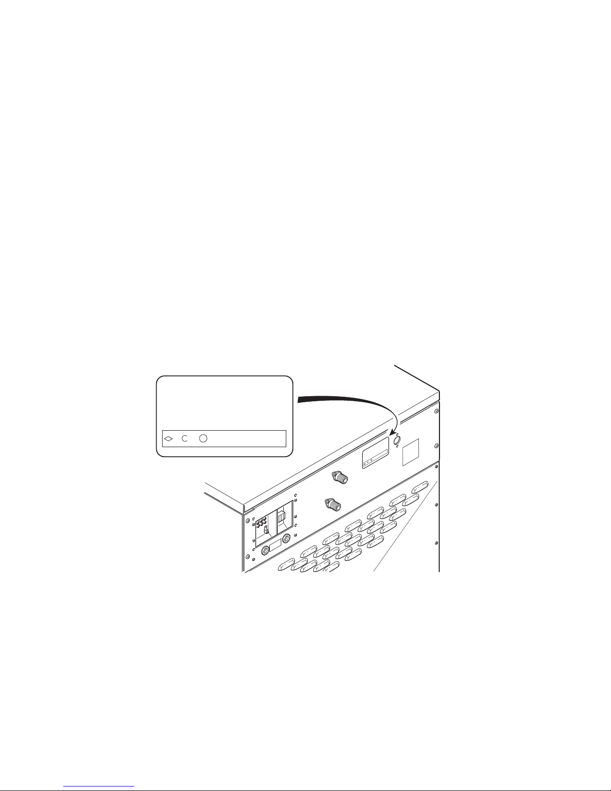
Nameplate Location
When calling or writing about your product, be sure to
mention model and serial numbers. Model and serial
numbers are located on nameplate(s) as shown.
Model No.
Serial No.
Voltage Amps
Required Circuit Breaker Amps.
Hz Wire Phase
Max. Load KG Max. Speed RPMLB
Elec. Heating
KW Steam Press PSI
BAR
For technical assistance, call (920) 748-3121.
Product No. Date Code
M
P
R
R
A
B
ps
m
A
d
e
.
e
o.
I
p
ps
S
S
se
l N
a
x.
Am
h
r
.
P
ode
Ma
o
ke
M
a
e
ss P
r
G
e
rial N
B
K
r
e
t
i
P
S
u
e
e
c
ir
m
g
a
a
W
e
Cir
t
olt
d
S
V
e
B
L
W
uir
ode
K
q
C
e
e
R
t
Da
d
z
a
H
o
L
g
n
i
x.
t
a
a
M
lec. He
E
.
No
t
duc
o
r
P
CHM2411P
F232202 7
© Copyright, Alliance Laundry Systems LLC – DO NOT COPY or TRANSMIT

Introduction
Model Identification
Information in this manual is applicable to these washer-extractors.
HC18MC2
HC18MD2
HC18MH2
HC18MN2
HC18MV2
HC18MX2
HC20MD2
HC20ML2
HC20MN2
HC20MX2
HC20MY2
HC25MC2
HC25MD2
HC25MH2
HC25ML2
HC25MN2
HC25MV2
HC25MX2
HC25MY2
HC27MC2
HC27MD2
HC27MH2
HC27MN2
HC27MV2
HC27MX2
HC30MD2
HC30ML2
HC30MN2
HC30MX2
HC30MY2
HC35MC2
HC35MD2
HC35MH2
HC35MN2
HC35MV2
HC35MX2
HC40MD2
HC40ML2
HC40MN2
HC40MX2
HC40MY2
HC50MC2
HC50MD2
HC50MH2
HC50ML2
HC50MN2
HC50MV2
HC50MX2
HC50MY2
HC60MD2
HC60ML2
HC60MN2
HC60MX2
HC60MY2
HC80MC3
HC80MD3
HC80MH3
HC80MN3
HC80MV3
SC18MC2
SC18MC3
SC18MD2
SC18MD3
SC18MH2
SC18MH3
SC18MN2
SC18MN3
SC18MV2
SC18MV3
SC18MX2
SC18MX3
SC20MD2
SC20ML2
SC20MN2
SC20MX2
SC20MY2
SC25MC2
SC25MD2
SC25MH2
SC25ML2
SC25MN2
SC25MV2
SC25MX2
SC25MY2
SC27MC2
SC27MD2
SC27MH2
SC27MN2
SC27MV2
SC27MX2
SC30MD2
SC30ML2
SC30MN2
SC30MX2
SC30MY2
SC35MC2
SC35MC3
SC35MD2
SC35MD3
SC35MH2
SC35MH3
SC35MN2
SC35MN3
SC35MV2
SC35MV3
SC35MX2
SC35MX3
SC40MD2
SC40ML2
SC40MN2
SC40MX2
SC40MY2
SC50MC2
SC50MC3
SC50MD2
SC50MD3
SC50MH2
SC50MH3
SC50ML2
SC50MN2
SC50MN3
SC50MV2
SC50MV3
SC50MX2
SC50MX3
SC50MY2
SC60MD2
SC60ML2
SC60MN2
SC60MX2
SC60MY2
SC80MC3
SC80MD3
SC80MH3
SC80MN3
SC80MV3
UC18MC2
UC18MC3
UC18MD2
UC18MD3
UC18MH2
UC18MH3
UC18MN2
UC18MN3
UC18MV2
UC18MV3
UC18MX2
UC18MX3
UC20MD2
UC20ML2
UC20MN2
UC20MX2
UC25MC2
UC25MD2
UC25MH2
UC25MN2
UC25MV2
UC25MX2
UC27MC2
UC27MD2
UC27MH2
UC27MN2
UC27MV2
UC27MX2
UC30ML2
UC30MN2
UC30MX2
UC35MC2
UC35MC3
UC35MD2
UC35MD3
UC35MH2
UC35MH3
UC35MN2
UC35MN3
UC35MV2
UC35MV3
UC35MX3
UC40MN2
UC50MC2
UC50MC3
UC50MD2
UC50MD3
UC50MH2
UC50MH3
UC50MN2
UC50MN3
UC50MV2
UC50MV3
UC50MX2
UC50MX3
UC60MN2
UC80MC3
UC80MD3
UC80MH3
UC80MN3
UC80MV3
8 F232202
© Copyright, Alliance Laundry Systems LLC – DO NOT COPY or TRANSMIT
Section 3
Troubleshooting
WARNING
To reduce the risk of electrical shock, fire, explosion, serious injury or death:
• Disconnect electrical power to the washer-extractor before servicing it.
• Close the gas shut-off valve to the washer-extractor (when applicable) before servicing it.
• Never start the washer-extractor with any guards/panels removed.
• Whenever ground wires are removed during servicing, these ground wires must be
reconnected to ensure that the washer-extractor is properly grounded.
W461R1
F232202 9
© Copyright, Alliance Laundry Systems LLC – DO NOT COPY or TRANSMIT
Troubleshooting
No Hot Fill Analysis (OPL)
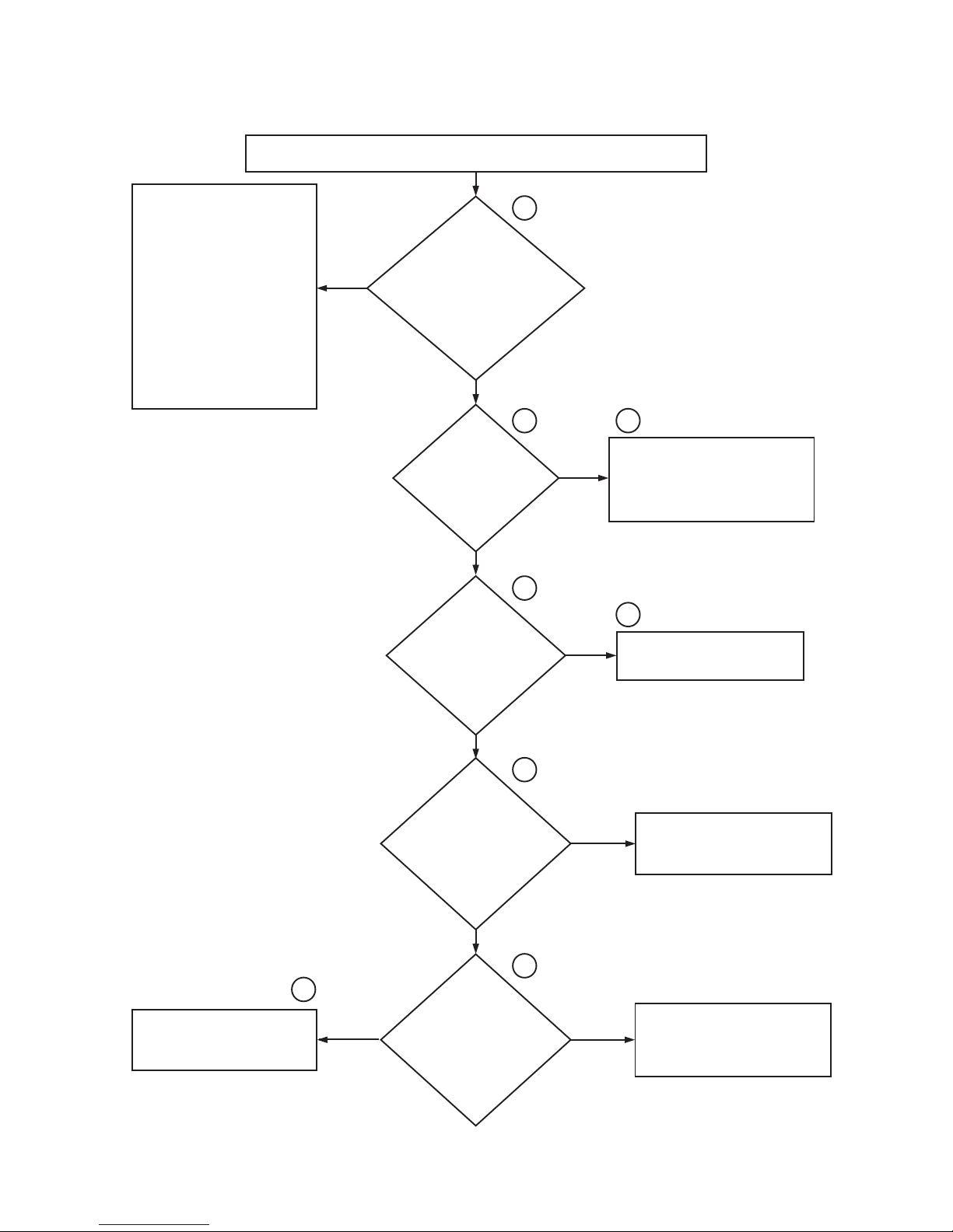
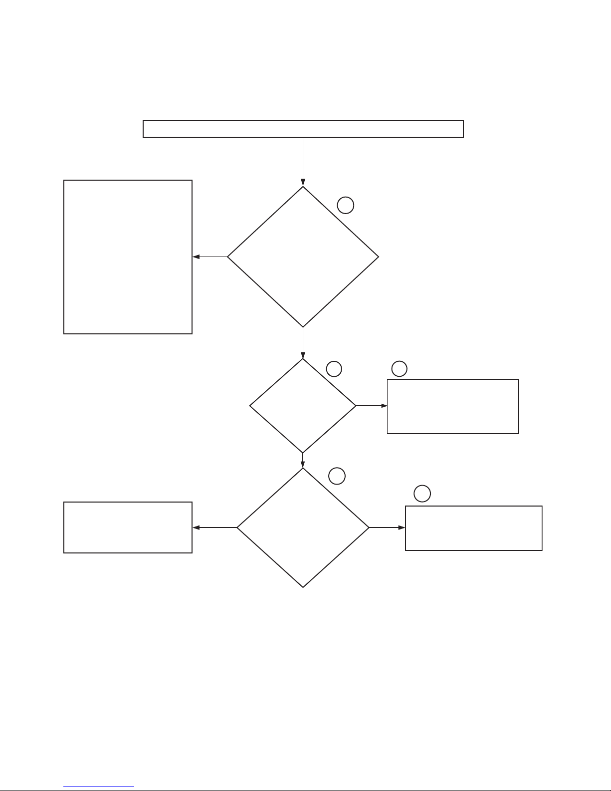
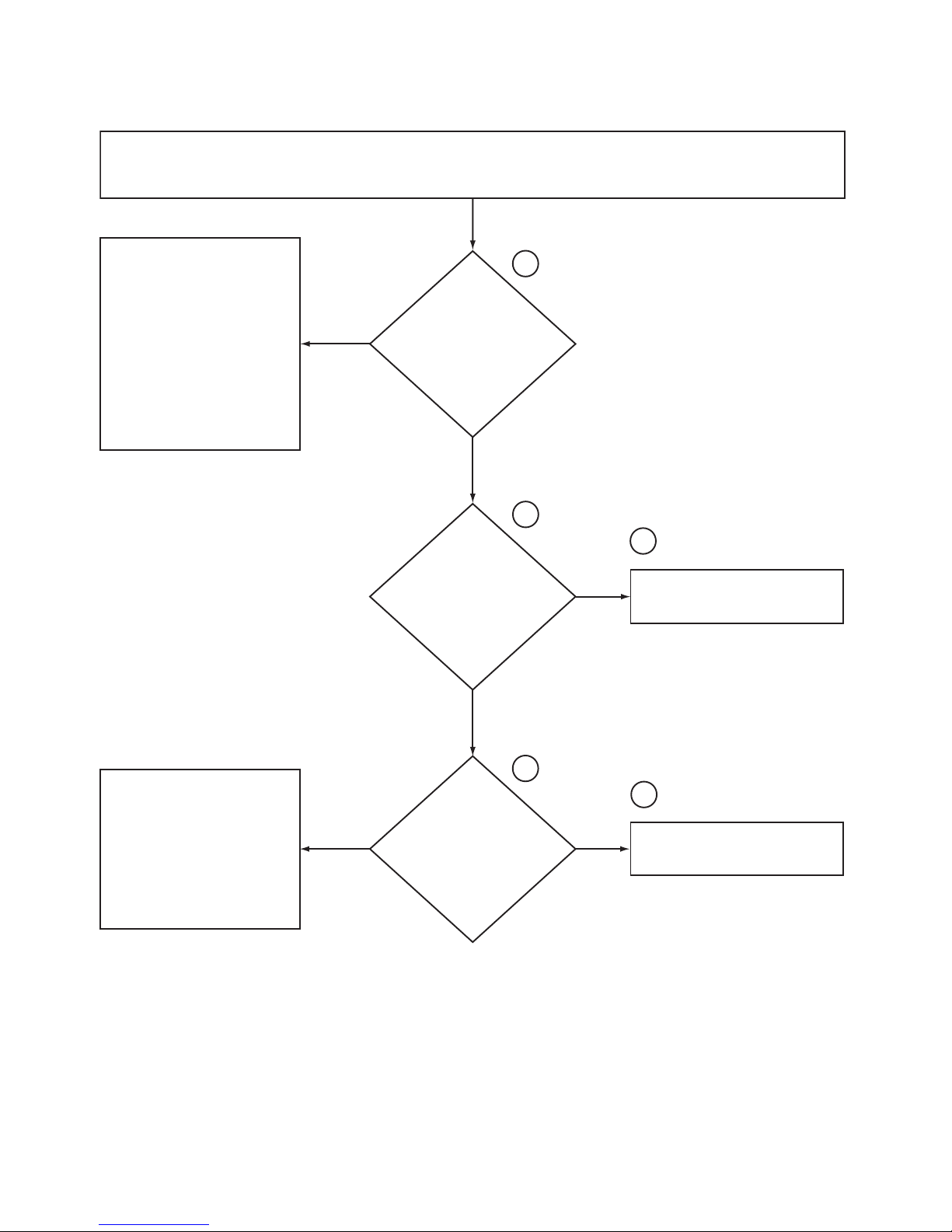
1. No Hot Fill Analysis (OPL)
With the water turned on to the machine and a cycle started, no hot water is filling the
machine when the
Check all hoses for blockage
between the YV1 and YV9 valve
ports and through the supply
dispenser, including the vacuum
breaker.
If there is no blockage, replace the
entire hot water valve or install a
repair kit onto the YV1 and/or YV9
valve ports. Please note that the
valve solenoid isn
service part.
Please refer to the
Hose (OPL)
location clarification.
’
t available as a
“
No Hot Fill
”
illustration for hose
“
Hot” button is pressed.
Volts* AC) at the YV1 valve
YES
solenoid across wires V1
(hot) and VN1 J9-1-9 (neutral)
and at the YV9 valve
solenoid across wires V9
from terminal strip 12
the
pushed on the cycle
selector, is there voltage
(120 Volts* AC) from G3
on the cycle selector to
Is there
voltage (120
(hot) and
VN9 (neutral)?
NO
Is
there voltage
(120 Volts* AC)
to terminal
strip 29**?
NO
With
“
Hot” button
terminal strip
29**?
1A
2A
4A
YES
YES
3A
Repair and/or replace the wire from
terminal strip 12 to the YV1 and/or YV9
valve solenoids as needed.
Please note that the wire goes through
valve harness connector J9-1-6.
5A
Repair and/or replace the wire from
G3 on the cycle selector to terminal
strip 12. This wire is named 44.
NO
6A
Is there
voltage (120
Volts* AC) from H3 on
the cycle selector to
terminal strip
29**?
NO
7A
8A
Repair and/or replace the wire
between 2b on the timer and H3 on
the cycle selector. This wire is
called 40.
*Note: All voltage readings are approximate.
**Note: All voltage readings should be taken from
terminal strip 29** as a neutral point.
10 F232202
© Copyright, Alliance Laundry Systems LLC – DO NOT COPY or TRANSMIT
YES
Is there
voltage (120
Volts* AC) from 2b on
the timer to terminal
strip 29**?
YES
NO
Replace the cycle selector switch.
Note: Please make sure that the hot
button on the switch is pressed.
Assuming that all checks were done
properly, replace the timer or contact
Alliance Laundry Systems
Service Department to verify that all
checks have been done correctly.
Customer
CHM281S

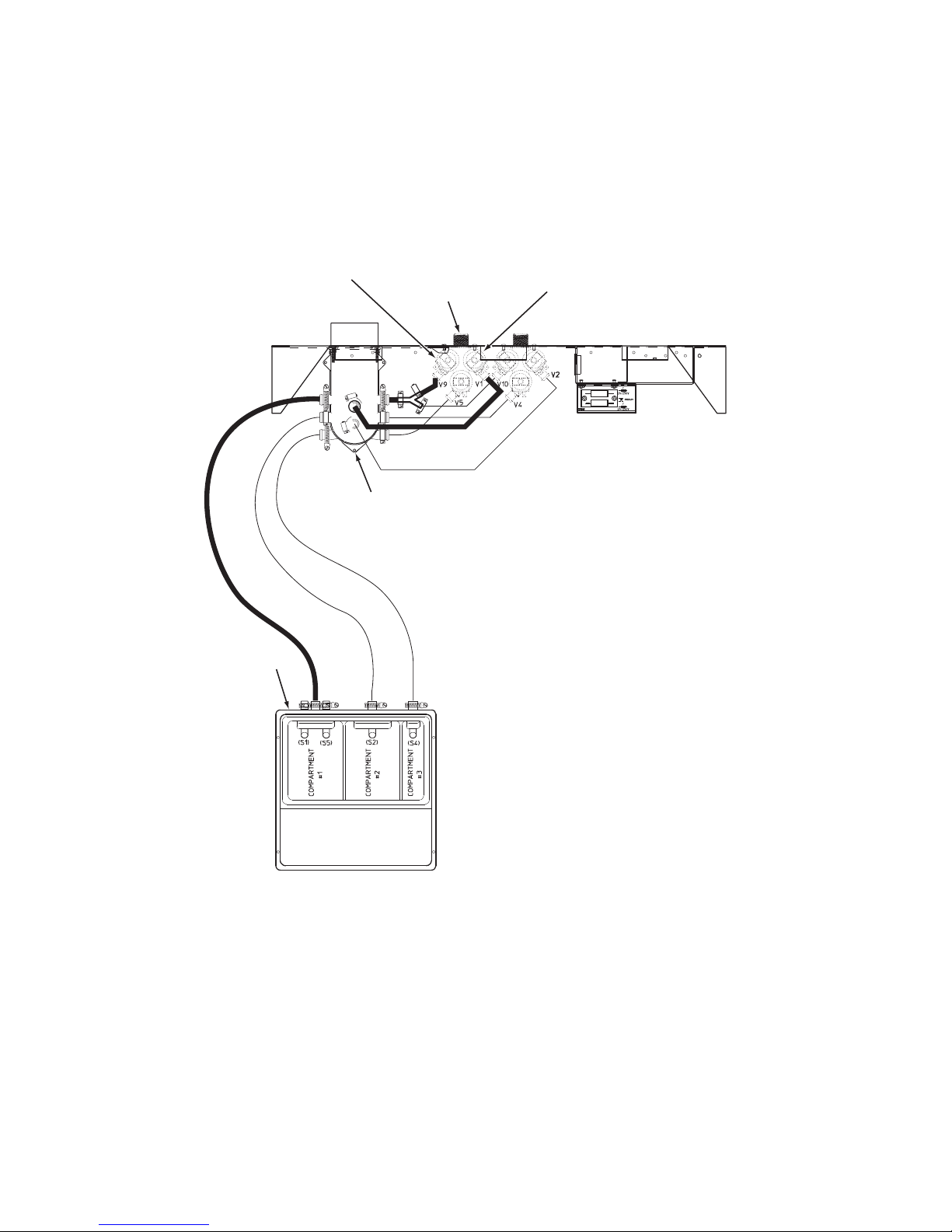
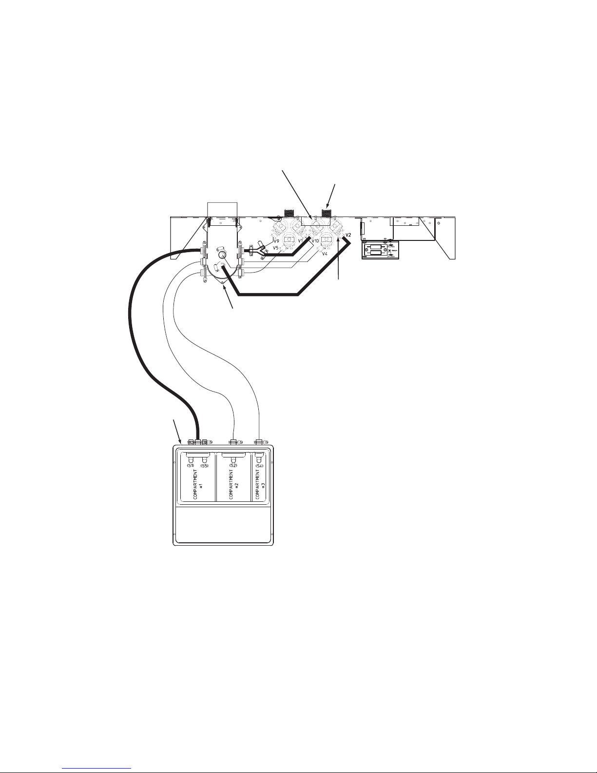
No Hot Fill Hose (OPL) Illustration
Troubleshooting
YV9 VALVE PORT / SOLENOID
SUPPLY DISPENSER
HOT WATER VALVE
VACUUM BREAKER
YV1 VALVE PORT / SOLENOID
Please refer to the following 2 pages for wiring diagram information.
F232202 11
© Copyright, Alliance Laundry Systems LLC – DO NOT COPY or TRANSMIT
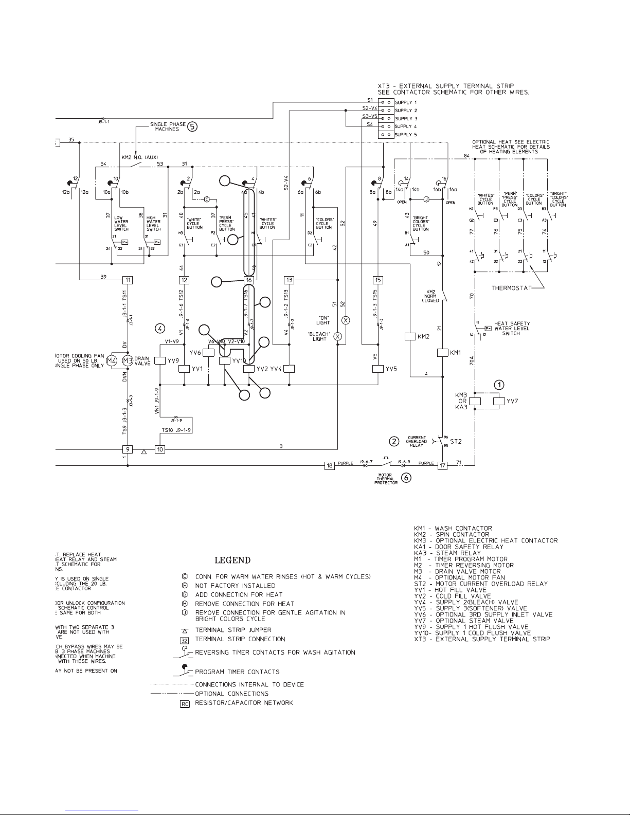
CHM277S
Troubleshooting
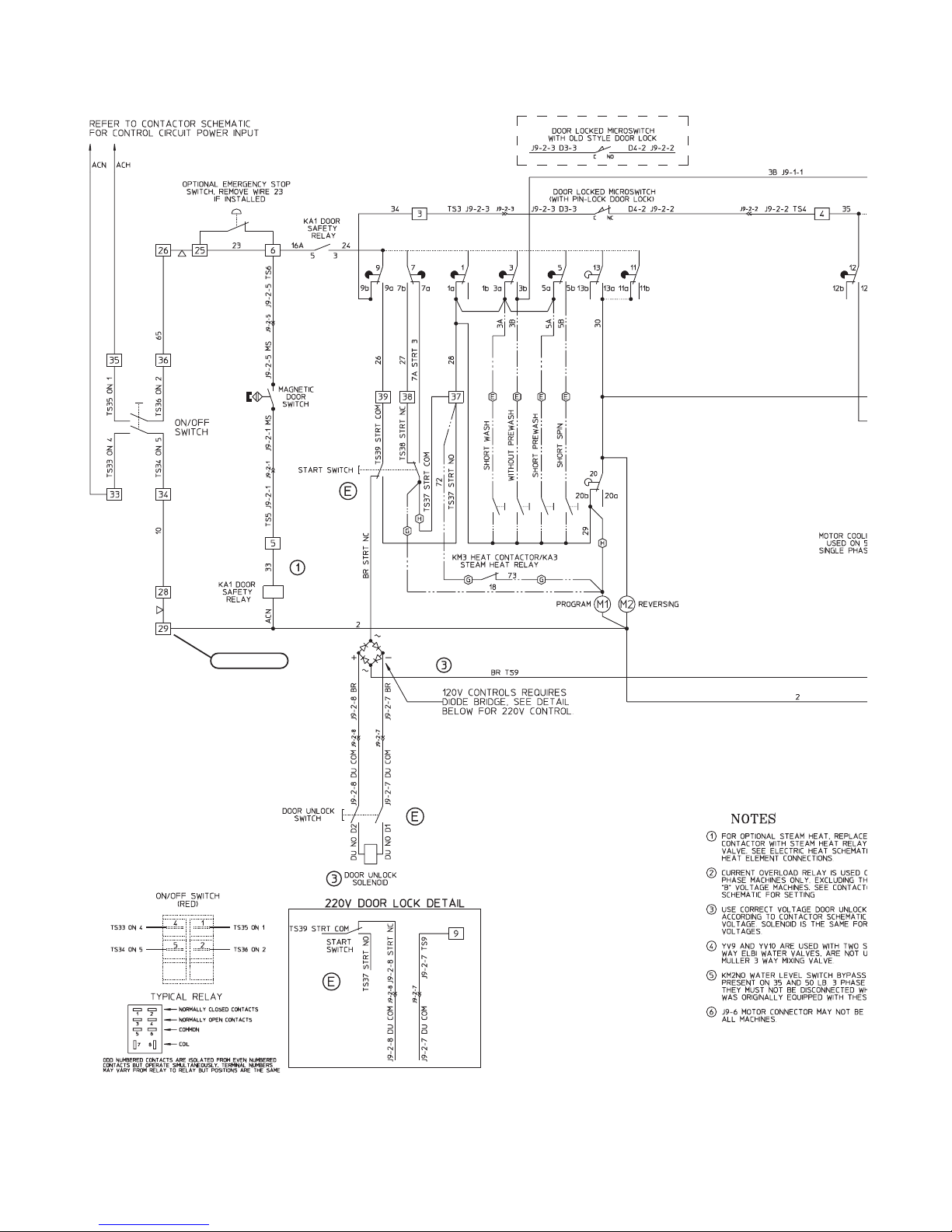
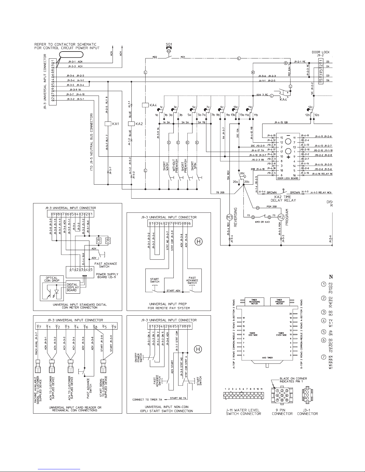
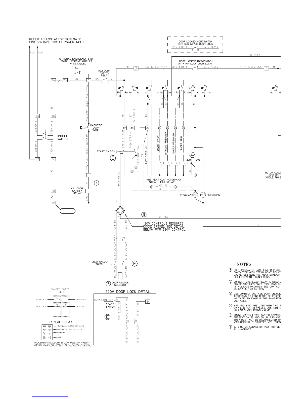
No Hot Fill Analysis (OPL) (Sheet 1 of 2)
2A, 4A, 6A and 7A
4
NOTE: Refer to the wiring diagram suplied with your machine.
12 F232202
© Copyright, Alliance Laundry Systems LLC – DO NOT COPY or TRANSMIT
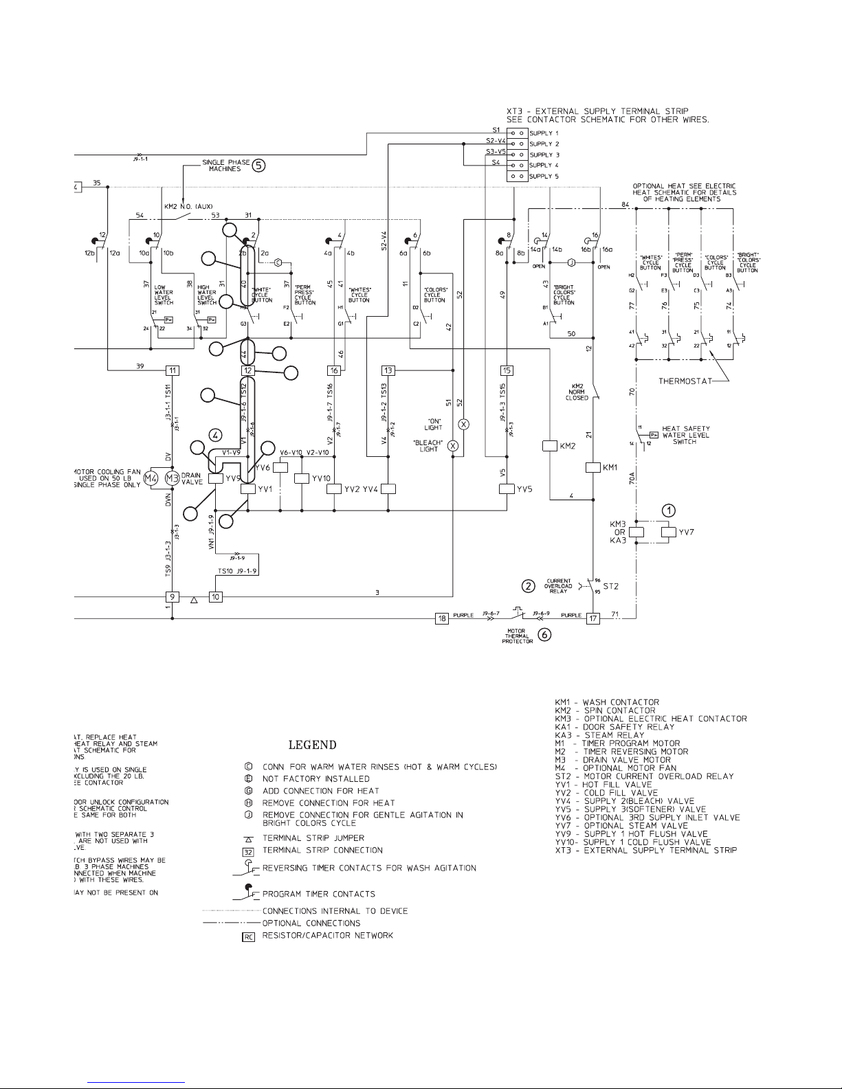
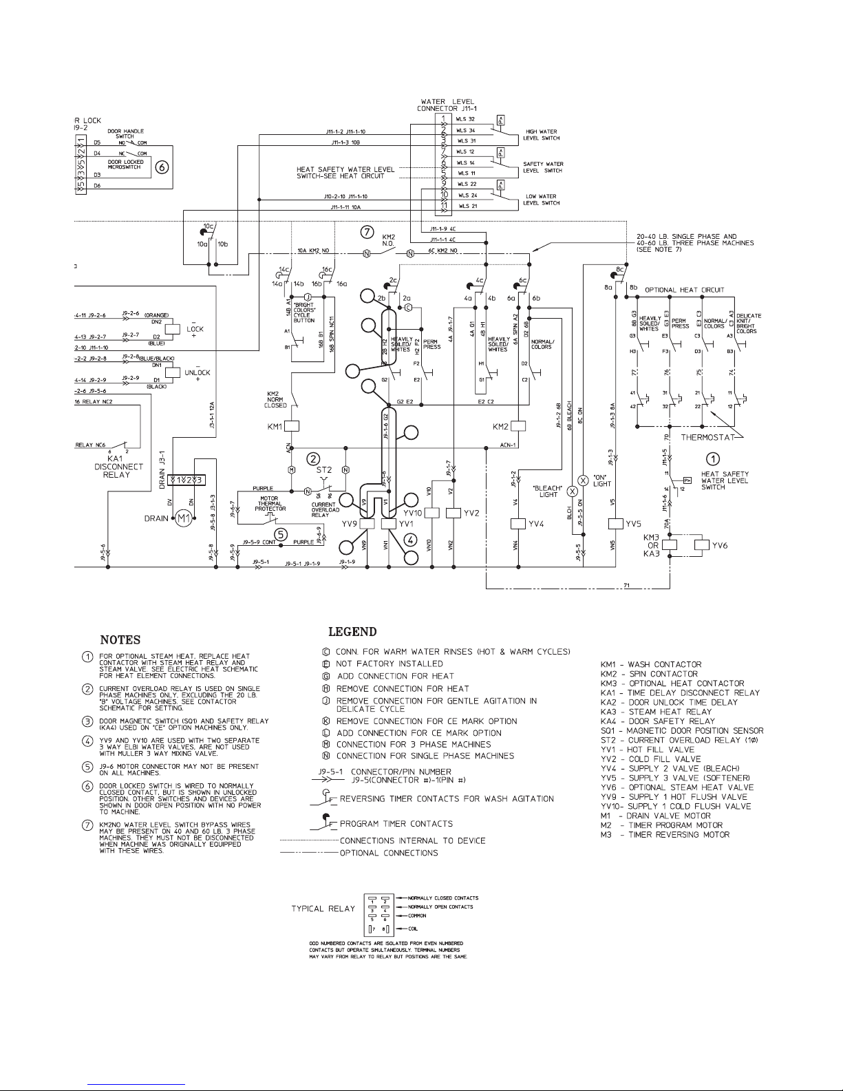
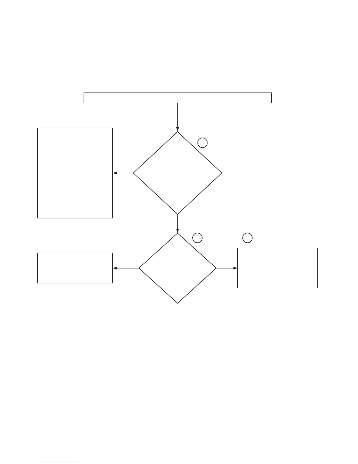
No Hot Fill Analysis (OPL) (Sheet 2 of 2)
7A
8A
6A
Troubleshooting
4A
3A
1A
1A
1A
5A
2A
1A
F232202 13
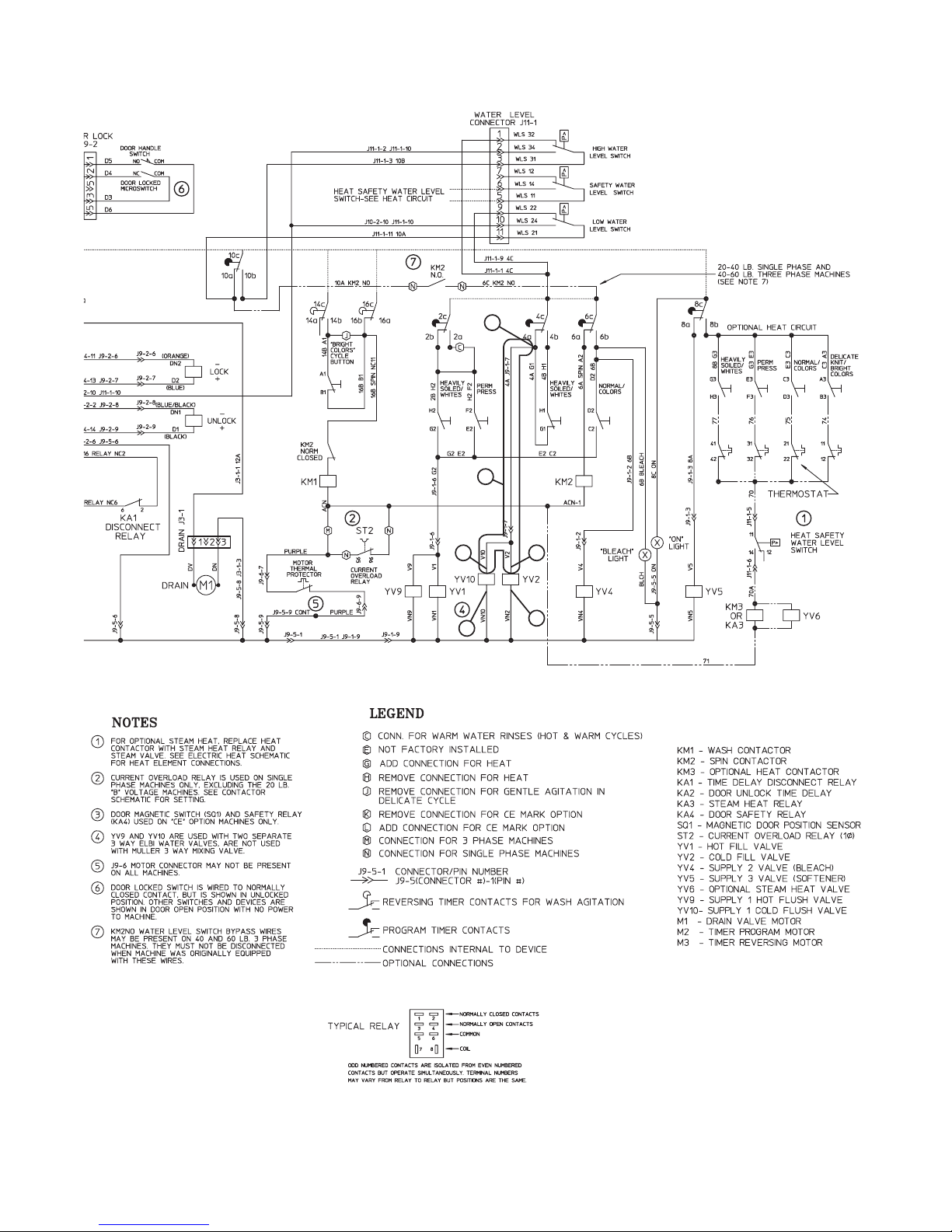
© Copyright, Alliance Laundry Systems LLC – DO NOT COPY or TRANSMIT
CHM282S
0635913(E)

Troubleshooting
No Hot Fill Analysis (Coin)
2. No Hot Fill Analysis (Coin)
With the water turned on to the machine and a cycle started, no hot water is filling the machine
when the
Check all hoses for blockage
between the YV1 and YV9 valve
ports and through the supply
dispenser, including the vacuum
breaker.
If there is no blockage, replace the
entire hot water valve or install a
repair kit onto the YV1 and/or YV9
valve ports. Please note that the valve
solenoid isn
part.
Please refer to the
(Coin)
clarification.
’
t available as a service
”
illustration for hose location
“
No Hot Fill Hose
“
Hot” button is pressed.
YES
1A
Is there voltage (120
Volts* AC) at the YV1 valve
solenoid across wires V1
(hot) and VN1 (neutral)
and at the YV9 valve
solenoid across wires V9
(hot) and VN9 (neutral)?
NO
2A
With the “Hot” button
pushed on the cycle
selector, is there voltage
(120 Volts* AC) from G2
on the cycle selector to
J9-3-1** on the input
connector?
YES
3A
Repair and/or replace the wire from G2
on the cycle selector, through J9-1-6
valve harness connector and to the YV1
and/or YV9 valve solenoids as needed.
This wire is named J9-1-6 G2.
Repair and/or replace the wire
between 2b on the timer and H2 on
the cycle selector. This wire is called
2BH2.
6A
YES
NO
Is there voltage (120
Volts* AC) from H2 on
the cycle selector to
J9-3-1** on the input
connector?
NO
Is there voltage (120
Volts* AC) from 2b on
the timer to J9-3-1** on
the input connector?
4A
5A
YES
NO
Replace the cycle selector switch.
Note: Please make sure that the hot
button on the switch is pressed.
Assuming that all checks were done
properly, replace the timer or contact
Alliance Laundry Systems
Service Department to verify that all
checks have been done correctly.
Customer
*Note: All voltage readings are approximate.
**Note: All voltage readings should be taken from input connector J9-3-1 as a neutral point.
14 F232202
© Copyright, Alliance Laundry Systems LLC – DO NOT COPY or TRANSMIT
CHM275S
No Hot Fill Hose (Coin) Illustration
Troubleshooting
YV9 VALVE PORT / SOLENOID
SUPPLY DISPENSER
HOT WATER VALVE
VACUUM BREAKER
YV1 VALVE PORT / SOLENOID
Please refer to the following 2 pages for wiring diagram information.
F232202 15
© Copyright, Alliance Laundry Systems LLC – DO NOT COPY or TRANSMIT
CHM277S
Troubleshooting
2A, 4A and 5A
No Hot Fill Analysis (Coin) (Sheet 1 of 2)
NOTE: Refer to the wiring diagram suplied with your machine.
16 F232202
© Copyright, Alliance Laundry Systems LLC – DO NOT COPY or TRANSMIT
No Hot Fill Analysis (Coin) (Sheet 2 of 2)
5A
6A
4A
2A
3A
Troubleshooting
1A
1A
1A
1A
F232202 17
© Copyright, Alliance Laundry Systems LLC – DO NOT COPY or TRANSMIT
CHM276S
0636156(H)
Troubleshooting
3. No Cold Fill Analysis (OPL)
No Cold Fill Analysis (OPL)
With the water turned on to the machine and a cycle started, no cold water is filling the machine.
Check all hoses for blockage
between the YV2 and YV10 valve
ports and through the supply
dispenser, including through the
vacuum breaker.
If there is no blockage, replace the
entire cold water valve or install a
repiar kit onto the YV2 and/or YV10
valve ports. Please note that the valve
solenoid isn’t available as a service
part.
Please refer to the “No Cold Fill Hose
(OPL)” illustration for hose location
clarification.
YES
1A
Is there
voltage (120
Volts* AC) at the YV2
valve solenoid across
wires V2 (hot) and VN1 J9-1-9
(neutral) and at the YV10
valve solenoid across
wires V10 (hot) and
VN1 J9-1-9
(neutral)?
NO
Assuming that all checks were done
properly, replace the timer or contact
Alliance Laundry Systems’ Customer
Service Department to verify that all
checks have been done correctly.
NO
Is
there voltage
(120 Volts* AC)
from terminal strip 16
to terminal
strip 29**?
NO
Is there
voltage (120
Volts* AC) from 4a on
the timer to
terminal
strip 29**?
2A
4A
YES
3A
Repair and/or replace the wire from
terminal strip 16 to the YV1 and/or YV9
valve solenoids as needed.
Please note that the wire goes through
valve harness connector J9-1-7.
5A
YES
Repair and/or replace the wire from 4a
on the timer to
wire is called 45.
terminal strip 16
. This
*Note: All voltage readings are approximate.
** Note: All voltage readings should be taken from
18 F232202
© Copyright, Alliance Laundry Systems LLC – DO NOT COPY or TRANSMIT
terminal strip 29** as a neutral point.
CHM283S
No Cold Fill Hose (OPL) Illustration
YV10 VALVE PORT / SOLENOID
COLD WATER VALVE
YV2 VALVE PORT / SOLENOID
VACUUM BREAKER
Troubleshooting
SUPPLY DISPENSER
CHM280S
Please refer to the following 2 pages for wiring diagram information.
F232202 19
© Copyright, Alliance Laundry Systems LLC – DO NOT COPY or TRANSMIT

Troubleshooting
No Cold Fill Analysis (OPL) (Sheet 1 of 2)
2A and 4A
4
NOTE: Refer to the wiring diagram suplied with your machine.
20 F232202
© Copyright, Alliance Laundry Systems LLC – DO NOT COPY or TRANSMIT
No Cold Fill Analysis (OPL) (Sheet 2 of 2)
4A
5A
2A
3A
1A
1A
Troubleshooting
1A
1A
F232202 21
© Copyright, Alliance Laundry Systems LLC – DO NOT COPY or TRANSMIT
CHM284S
0635913(E)
Troubleshooting
4. No Cold Fill Analysis (Coin)
No Cold Fill Analysis (Coin)
With the water turned on to the machine and a cycle started, no cold water is filling the machine.
Check all hoses for blockage
between the YV2 and YV10 valve
ports and through the supply
dispenser, including through the
vacuum breaker.
If there is no blockage, replace the
entire cold water valve or install a
repiar kit onto the YV2 and/or YV10
valve ports. Please note that the valve
solenoid isn’t available as a service
part.
YES
1A
Is there voltage (120
Volts* AC) at the YV2
valve solenoid across
wires V2 (hot) and VN2
(neutral) and at the YV10
valve solenoid across
wires V10 (hot) and VN10
(neutral)?
Please refer to the “No Cold Fill Hose
(Coin)” illustration for hose location
clarification.
Assuming that all checks were done
properly, replace the timer or contact
Alliance Laundry Systems’ Customer
Service Department to verify that all
checks have been done correctly.
*Note: All voltage readings are approximate.
** Note: All voltage readings should be taken from input connector J9-3-1 as a neutral point.
NO
Is there voltage (120
Volts* AC) from 4a on
the timer to input
connector J9-3-1**?
NO
2A
YES
3A
Repair and/or replace the wire from 4a
on the timer to the YV2 and/or YV10
valve solenoids as needed.
Please note that this wire goes through
valve harness connector J9-1-7.
CHM278S
22 F232202
© Copyright, Alliance Laundry Systems LLC – DO NOT COPY or TRANSMIT

No Cold Fill Hose (Coin) Illustration
YV10 VALVE PORT / SOLENOID
COLD WATER VALVE
YV2 VALVE PORT / SOLENOID
VACUUM BREAKER
Troubleshooting
SUPPLY DISPENSER
CHM280S
Please refer to the following 2 pages for wiring diagram information.
F232202 23
© Copyright, Alliance Laundry Systems LLC – DO NOT COPY or TRANSMIT

Troubleshooting
2A
No Cold Fill Analysis (Coin) (Sheet 1 of 2)
NOTE: Refer to the wiring diagram suplied with your machine.
24 F232202
© Copyright, Alliance Laundry Systems LLC – DO NOT COPY or TRANSMIT
No Cold Fill Analysis (Coin) (Sheet 2 of 2)
2A
3A
Troubleshooting
1A
1A
1A
1A
F232202 25
© Copyright, Alliance Laundry Systems LLC – DO NOT COPY or TRANSMIT
CHM279S
0636156(H)
Troubleshooting
5. No Supply 2 Fill Analysis (OPL)
With the machine beginning the wash step, no water is coming into the supply compartment #2. Please be sure that all other cycle steps have
been performed properly up to the wash. Please refer to the "Cycle Timer Wash Step" illustration for timer position clarification.
Note: The following voltage readings must be taken within 30-60 seconds from the start of the wash step, as close as possible to the start of the
wash step. The bleach light will be lit at this time.
Check all hoses for blockage
between the YV4 valve port and the
supply dispenser, including through
the vacuum breaker.
If there is no blockage, replace the
entire cold water valve or install a
repair kit onto the YV4 valve port.
Please note that the valve solenoid
isn't available as a service part.
Please refer to the "Supply 2 Fill
Hose" illustration for hose location
clarification.
YES
Is there voltage (120
Volts** AC) at the YV4
valve solenoid across
wires V4 (hot) and VN1
J9-1-9 (neutral)?
NO
Is there voltage (120
Volts** AC) from
terminal strip 13 to
terminal strip 29*?
NO
1A
2A
YES
3A
Check the wiring between terminal strip
13 and the YV4 valve solenoid. Repair
and/or replace the wire as needed.
Assuming that all checks were done
properly, replace the timer or contact
Alliance Laundry Systems' Customer
Service Department to verify that all
checks have been done correctly.
Please remember that all voltage
readings must be taken within 30-60
seconds from the start of the wash
step.
*Note: All voltage readings should be taken from terminal 29 as a neutral point.
**Note: All voltage readings are approximate.
26 F232202
© Copyright, Alliance Laundry Systems LLC – DO NOT COPY or TRANSMIT
NO
Is there voltage (120
Volts** AC) from 6b on
the timer to terminal
strip 29*?
4A
YES
5A
Repair and/or replace the wire between
6b on the timer and terminal strip 13 as
needed.
CHM272S

Troubleshooting
Please refer to the following 2 pages for wiring diagram information.
F232202 27
© Copyright, Alliance Laundry Systems LLC – DO NOT COPY or TRANSMIT
Troubleshooting
No Supply 2 Fill Analysis (OPL) (Sheet 1 of 2)
2A and 4A
NOTE: Refer to the wiring diagram suplied with your machine.
28 F232202
© Copyright, Alliance Laundry Systems LLC – DO NOT COPY or TRANSMIT
 Loading...