

Alliance Laundry Systems NX18BVPA6, NX18BVQA7, NX18BVPA7, NX18BVQA6, NX18BVXA6 Basic Installation/operation
...Page 1
Washer-Extractors
Cabinet Freestanding
Coin Models
Basic Installation/Operation
Keep These Instructions for Future Reference.
(If this machine changes ownership, this manual must accompany machine.)
www.comlaundry.com
Part No. 9002062R3
January 2010
Page 2

Page 3

Table of
Content s
Introduction......................................................................................... 2
Model Identification ............................................................................. 2
Safety Information.............................................................................. 3
Explanation of Safety Messages........................................................... 3
Important Safety Instructions ............................................................... 3
Safety Decals........................................................................................ 5
Operator Safety....................................................................... ..... ......... 6
Specifications and Dimensions........................................................... 7
Installation........................................................................................... 13
Dimensional Clearances................................................................... 13
Machine Foundation ........................................................................ 13
Mounting Bolt Installation (If Required).............................................. 14
Removing the Transport Block............................................................. 15
Operation............................................................................................. 17
Control Panel............................. .... ..... .................................................. 17
Operating Instructions .......................................................................... 18
Disposal of Unit................................................................................... 20
© Copyright 2010, Alliance Laundry Systems LLC
All rights reserved. No part of the contents of this book may be reproduced or transmitted in any form or by any
means without the expressed written consent of the publisher.
9002062
© Copyright, Alliance Laundry Systems LLC – DO NOT COPY or TRANSMIT
1
Page 4
Introduction
Model Identification
Information in this manual is applicable to these
models:
18
30
33
40
NX18BVPA6
NX18BVPA7
NX18BVQA6
NX30BVPA6
NX30BVPA7
NX30BVQA6
SX33BVPA7 SX33BVQA7 SX33BVXA7 SX33BVXM7
SX40BVPA7 SX40BVQA7 SX40BVXA7 SX40BVXM7
NX18BVQA7
NX18BVXA6
NX18BVXA7
NX30BVXM7
NX30BVQA7
NX30BVXA6
NX18BVXM7
SX18BVPA7
SX18BVQA7
NX30BVXA7
SX30BVPA7
SX30BVQA7
SX18BVXA7
SX18BVXM7
SX30BVXA7
SX30BVXM7
2
© Copyright, Alliance Laundry Systems LLC – DO NOT COPY or TRANSMIT 9002062
Page 5
Safety Information
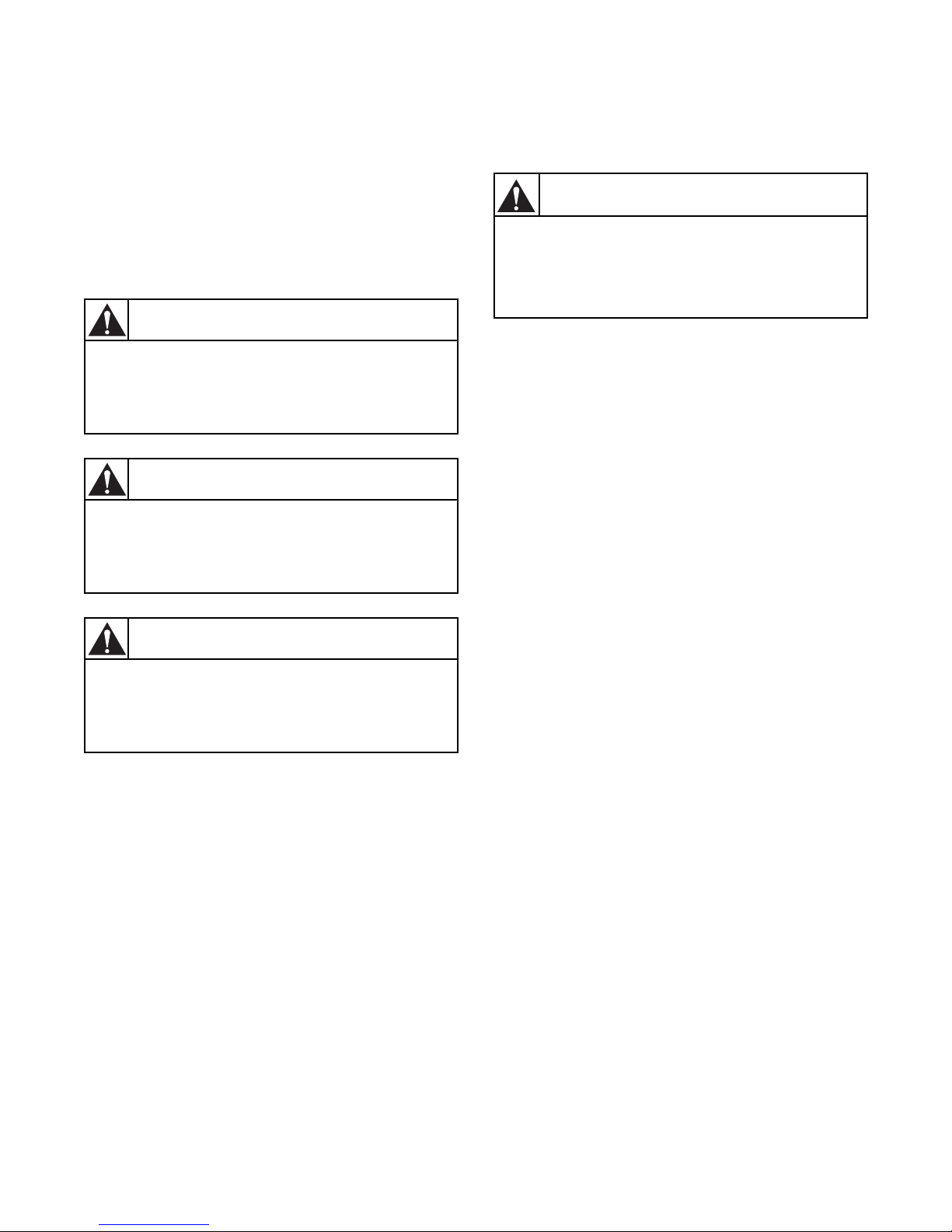
DANGER indicates the presence of a
hazard that will cause severe personal
injury, death, or substantial property
damage if the danger is ignored.
DANGER
WARNING indicates the presence of a
hazard that can cause severe personal
injury, death, or substantial property
damage if the warning is ignored.
WARNING
CAUTION indicates the presence of a
hazard that will or can cause minor
personal injury or property damage if the
caution is ignored.
CAUTION
To reduce the risk of fire, electric shock,
serious injury or death to persons when
using your washer, follow these basic
precautions:
W023
WARNING
Explanation of Safety Messages
Precautionary statements (“DANGER,” “W ARNING ,”
and “CAUTION”), followed by specific instructions,
are found in this manual and on machine decals. These
precautions are intended for the personal safety of the
operator, user, servicer, and those maintaining the
machine.
Important Safety Instructions
1. Read all instructions before using the washer.
2. Refer to the GROUNDING INSTRUCTIONS in
the INSTALLATION manual for the proper
grounding of the washer.
3. Do not wash textiles that have been previously
cleaned in, washed in, soaked in, or spotted with
gasoline, kerosene, waxes, cooking oils, drycleaning solvents, or other flammable or
explosive substances as they give off vapors that
could ignite or explode.
4. Do not add gasoline, dry-cleaning solvents, or
other flammable or explosive substances to the
wash water. These substances give off vapors that
could ignite or explode.
Additional precautionary statements (“IMPORTANT”
and “NOTE”) are followed by specific instructions.
IMPORTANT: The word “IMPORT ANT” is used
to inform the reader of specific procedures where
minor machine damage will occur if the procedure
is not followed.
NOTE: The word “NOTE” is used to communicate
installation, operation, maintenance or servicing
information that is important but not hazard
related.
5. Under certain conditions, hydrogen gas may be
produced in a hot water system that has not been
used for two weeks or more. HYDROGEN GAS
IS EXPLOSIVE. If the hot water system has not
been used for such a period, before using a
washing machine or combination washer-dryer,
turn on all hot water faucets and let the water
flow from each for several minutes. This will
release any accumulated hydrogen gas. The gas
is flammable, do not smoke or use an open flame
during this time.
6. Do not allow children to play on or in the washer .
Close supervision of children is necessary when
the washer is used near children. This is a safety
rule for all appliances.
7. Before the washer is removed from service or
discarded, remove the door to the washing
compartment.
8. Do not reach into the washer if the wash drum is
moving.
9002062
© Copyright, Alliance Laundry Systems LLC – DO NOT COPY or TRANSMIT
3
Page 6

Safety Information
9. Do not install or store the washer where it will be
exposed to water and/or weather.
10. Do not tamper with the controls.
11. Do not repair or replace any part of the washer , or
attempt any servicing unless specifically
recommended in the user-maintenance
instructions or in published user-repair
instructions that the user understands and has the
skills to carry out.
12. T o reduce the risk of an electric shock or fire, DO
NOT use an extension cord or an adapter to
connect the washer to the electrical power
source.
13. Use washer only for its intended purpose,
washing textiles.
14. Never wash machine parts or automotive parts in
the machine. This could result in serious damage
to the basket.
15. ALWAYS disconnect the washer from electrical
supply before attempting any service. Disconnect
the power cord by grasping the plug, not the cord.
16. Install the washer according to the
INSTALLATION INSTRUCTIONS. All
connections for water, drain, electrical power and
grounding must comply with local codes and be
made by licensed personnel when required.
17. To reduce the risk of fire, textiles which have
traces of any flammable substances such as
vegetable oil, cooking oil, machine oil,
flammable chemicals, thinner, etc., or anything
containing wax or chemicals such as in mops and
cleaning cloths, must not be put into the washer.
These flammable substances may cause the
fabric to catch on fire by itself.
20. If the supply cord is damaged, it must be replaced
by a special cord or assembly available from the
manufacturer or its service agent.
21. Be sure water connections have a shut-off valve
and that fill hose connections are tight. CLOSE
the shut-off valves at the end of each wash day.
22. Loading door MUST BE CLOSED any time the
washer is to fill, tumble or spin. DO NOT bypass
the loading door switch by permitting the washer
to operate with the loading door open.
23. Always read and follow manufacturer’s
instructions on packages of laundry and cleaning
aids. Heed all warnings or precautions. T o reduce
the risk of poisoning or chemical burns, keep
them out of the reach of children at all times
(preferably in a locked cabinet).
24. Always follow the fabric care instructions
supplied by the textile manufacturer.
25. Never operate the washer with any guards and/or
panels removed.
26. DO NOT operate the washer with missing or
broken parts.
27. DO NOT bypass any safety devices.
28. Failure to install, maintain, and/or operate this
washer according to the manufacturer’s
instructions may result in conditions which can
produce bodily injury and/or property damage.
NOTE: The WARNINGS and IMPORTANT
SAFETY INSTRUCTIONS appearing in this
manual are not meant to cover all possible
conditions and situations that may occur. Common
sense, caution and care must be exercised when
installing, maintaining, or operating the washer.
18. Do not use fabric softeners or products to
eliminate static unless recommended by the
manufacturer of the fabric softener or product.
19. Keep washer in good condition. Bumping or
dropping the washer can damage safety features.
If this occurs, have washer checked by a
qualified service person.
4
© Copyright, Alliance Laundry Systems LLC – DO NOT COPY or TRANSMIT
Any problems or conditions not understood should be
reported to the dealer, distributor, service agent or the
manufacturer.
9002062
Page 7
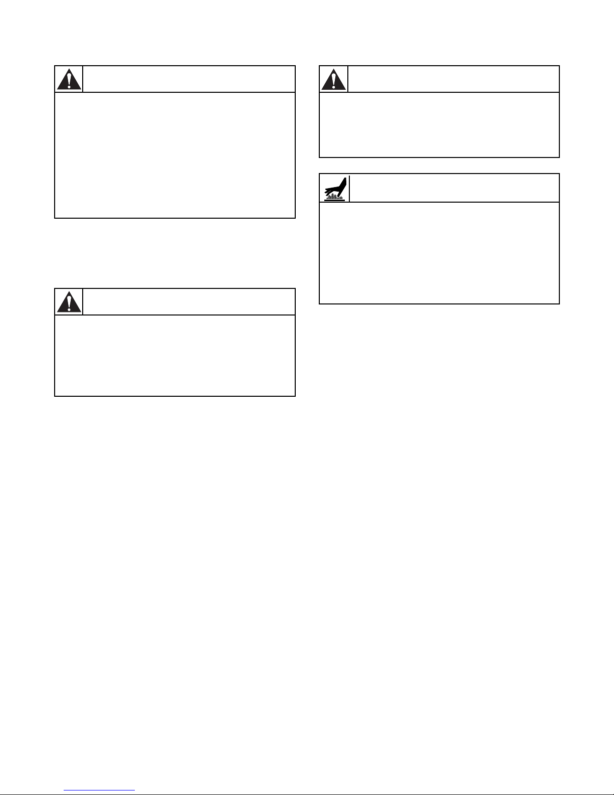
IMPORTANT: Ensure that the recommended
This machine must be installed, adjusted,
and serviced by qualified electrical
maintenance personnel familiar with the
construction and operation of this type of
machinery. They must also be familiar
with the potential hazards involved.
Failure to observe this warning may result
in personal injury and/or equipment
damage, and may void the warranty.
SW004
WARNING
Install the machine on a level floor of
sufficient strength. Failure to do so may
result in conditions which can produce
serious injury, death and/or property
damage.
W703
WARNING
Be careful around the open door,
particularly when loading from a level
below the door. Impact with door edges
can cause personal injury.
SW025
CAUTION
Never touch internal or external steam
pipes, connections, or components.
These surfaces can be extremely hot and
will cause severe burns. The steam must
be turned off and the pipe, connections,
and components allowed to cool before
the pipe can be touched.
SW014
WARNING
clearances for inspection and maintenance
are provided. Never allow the inspection and
maintenance space to be blocked.
Safety Information
Safety Decals
Safety decals appear at crucial locations on the
machine. Failure to maintain legible safety decals
could result in injury to the operator or service
technician.
To provide person al safety and keep the machine in
proper working order, follow all maintenance and
safety procedures presented in this manual. If
questions regarding safety arise, contact the
manufacturer immediately.
Use manufacturer-authorized spare parts to avoid
safety hazards.
9002062
© Copyright, Alliance Laundry Systems LLC – DO NOT COPY or TRANSMIT
5
Page 8
Safety Information
NEVER insert hands or objects into
basket until it has completely stopped.
Doing so could result in serious injury.
SW012
WARNING
Never operate the machine with a
bypassed or disconnected balance
system. Operating the machine with
severe out-of-balance loads could result
in personal injury and serious equipment
damage.
SW039
WARNING
Operator Safety
To ensure the safety of machine operators, the
following maintenance checks must be performed
daily:
1. Prior to operating the machine, verify that all
warning signs are present and legible. Missing or
illegible signs must be replaced immediately.
Make certain that spares are available.
2. Check door interlock before starting operation of
the machine:
a. Attempt to start the machine with the door
open. The machine should not start with the
door open.
b. Close the door without locking it and attempt
to start the machine. The machine should not
start with the door unlocked.
Do not bypass any safety devices in the machine.
c. Close and lock the door and start a cycle.
Attempt to open the door while the cycle is in
progress. The door should not open.
If the door lock and interlock are not functioning
properly, call a service technician.
3. Do not attempt to operate the machine if any of
the following conditions are present:
a. The door does not remain securely locke d
during the entire cycle.
b. Excessively high water level is evident.
c. Machine is not connected to a properly
grounded circuit.
6
© Copyright, Alliance Laundry Systems LLC – DO NOT COPY or TRANSMIT
9002062
Page 9
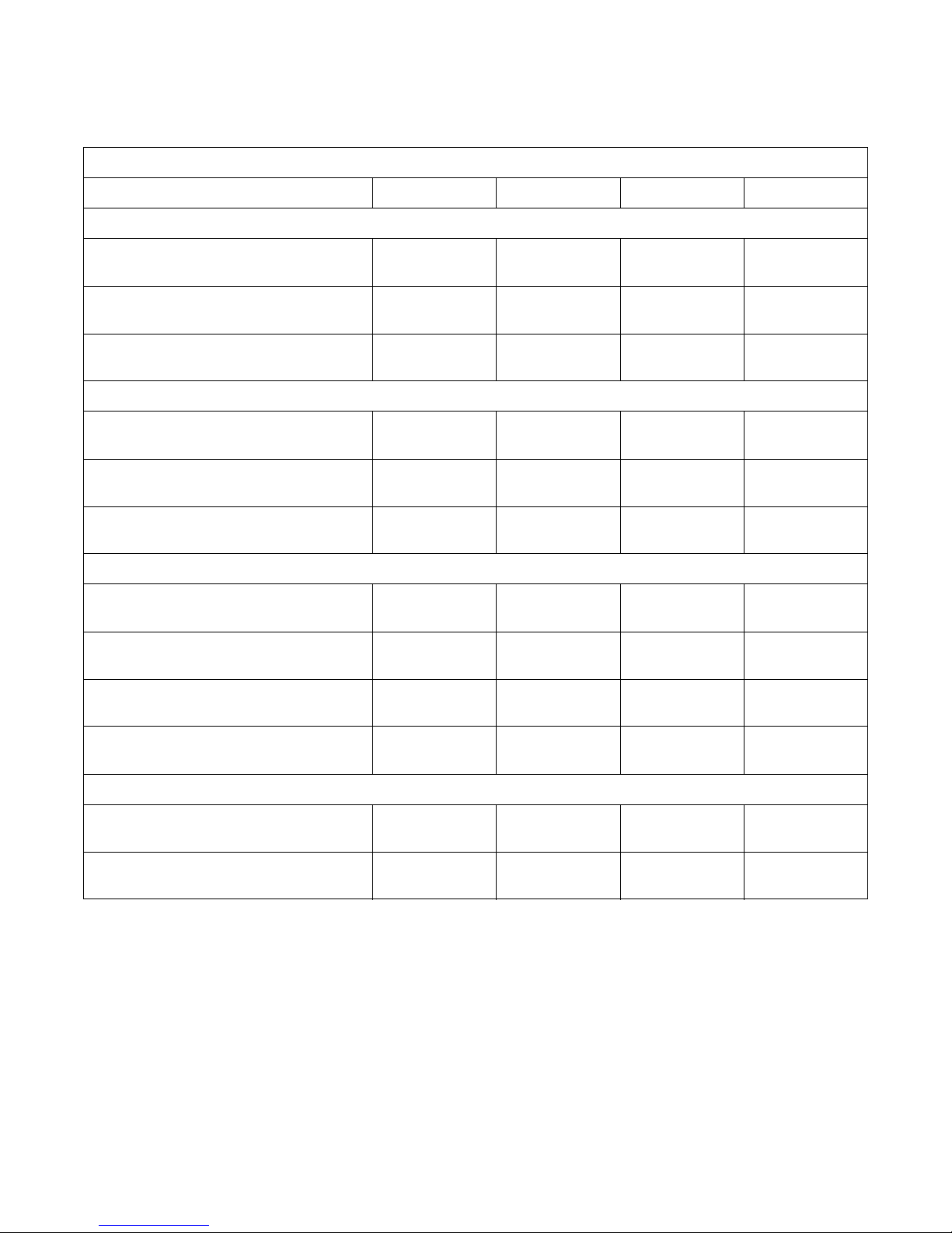
Specifications and Dimensions
Model 18303340
Overall Dimensions
General Specifications
Overall width
Overall height
Overall depth
Weight and Shipping Information
Net weight
Shipping weight
Shipping volume
Wash Cylinder Information
Cylinder diameter
Cylinder depth
Cylinder volume
660 mm
(26 in.)
1038 mm
(40.9 in.)
739 mm
(29.1 in.)
211 kg
(465.2 lb.)
233 kg
(513.7 lb.)
3
0.8 m
(22.5 ft
3
530 mm
(20.9 in.)
330 mm
(13 in.)
76 l
3
(2.7 ft
)
780 mm
(30.7 in.)
1202 m
(47.3 in.)
842 mm
(33.1 in.)
325kg
(716.5 lb.)
355 kg
(782.6 lb.)
3
1.3 m
3
)
(34.7 ft
)
650 mm
(25.6 in.)
400 mm
(15.76 in.)
132 l
(4.66 ft3)
780 mm
(30.7 in.)
1376 mm
(54.15 in.)
840 mm
(33.07 in.)
368 kg
(811.30 lb.)
383 kg
(844.37 lb.)
3
1.21 m
(42.83 ft3)
680 mm
(26.77 in.)
400 mm
(15.75 in.)
145 l
(5.12 ft3)
780 mm
(30.7 in.)
1376 mm
(54.15 in.)
940 mm
(37.01 in.)
391 kg
(862.01 lb.)
418 kg
(921.53 lb.)
3
1.3 m
(45.98 ft
3
680 mm
(26.77 in.)
500 mm
(19.69 in.)
181 l
(6.39 ft3)
)
Perforation size
Door Opening Information
Door opening size
Height of door bottom above floor
9002062
© Copyright, Alliance Laundry Systems LLC – DO NOT COPY or TRANSMIT
3mm
(0.12 in.)
300 mm
(11.8 in.)
280 mm
(11 in.)
3mm
(0.12 in.)
300 mm
(11.8 in.)
381 mm
(15 in.)
3 mm
(0.12 in.)
400 mm
(15.75 in.)
472 mm
(18.58 in.)
3 mm
(0.12 in.)
400 mm
(15.75 in.)
472 mm
(18.58 in.)
7
Page 10
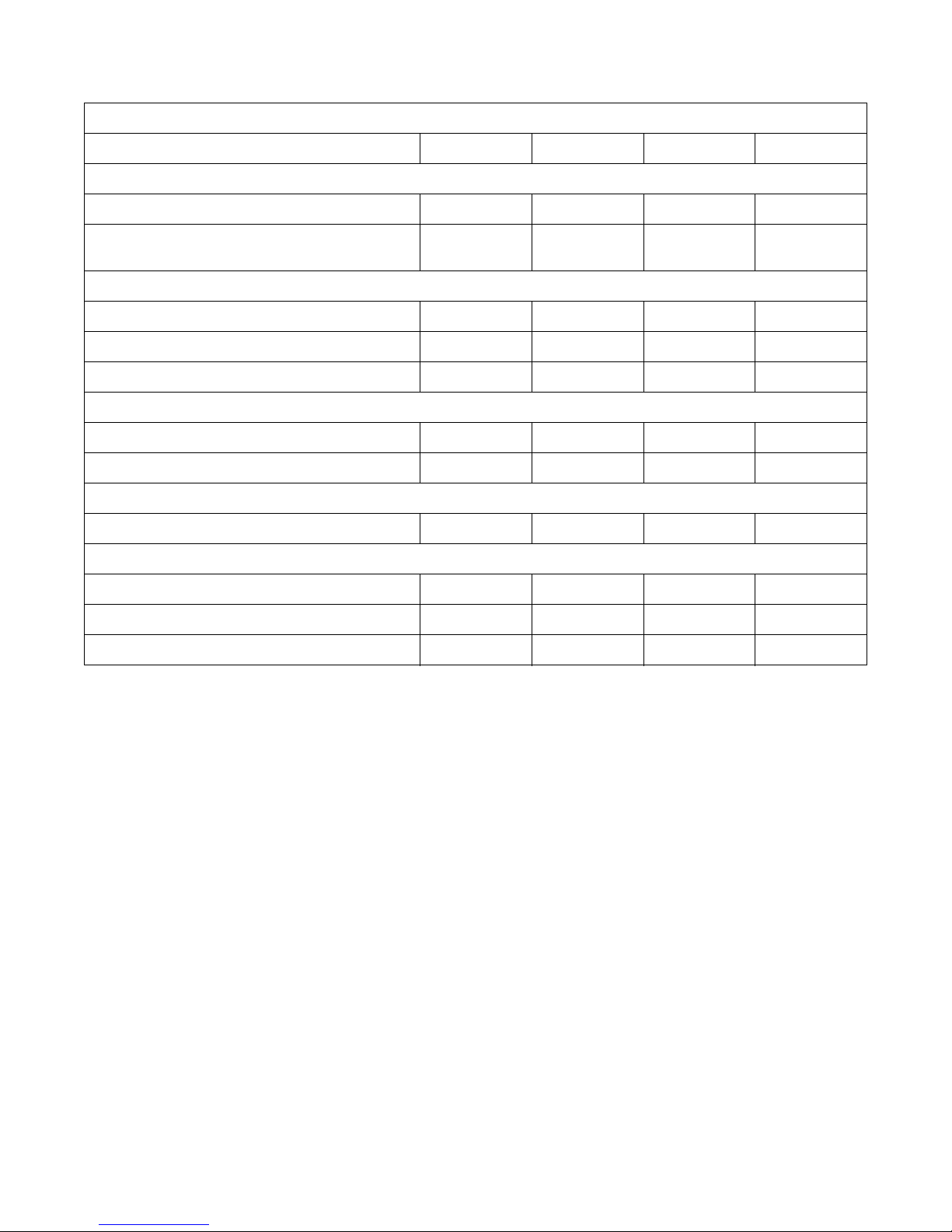
Specifications and Dimensions
Model 18303340
Drive Train Information
General Specifications
Number of motors in drive train
Drive motor power
Cylinder Speeds
Wash/reverse speed
Distribution/drain speed
Extract speed
Centrifugal Force Data
Wash/reverse centrif ugal force
Extract centrifugal force
Balance Detection
Vibration safety switch installed
Electrical Heating (International Models Only)
Total electrical heating capacity
Electrical heating elements
Electrical heat element size
1111
1 HP (0.75 kW) 2 HP
(1.5 kW)
2.95 HP
(2.2 kW)
2.95 HP
(2.2 kW)
10-50 RPM 10-50 RPM 10-50 RPM 10-50 RPM
85 RPM 85 RPM 85 RPM 85 RPM
250-1000 RPM 250-1000 RPM 250-1000 RPM 250-1000 RPM
0.03-0.74 Gs 0.04-0.91 Gs 0.37-0.94 Gs 0.37-0.94 Gs
19-296 Gs 23-363 Gs 24-377 Gs 24-377 Gs
Standard Standard Standard Standard
9 kW 18 kW 18 kW 18 kW
3666
3 kW 3 kW 3 kW 3 kW
8
© Copyright, Alliance Laundry Systems LLC – DO NOT COPY or TRANSMIT
9002062
Page 11
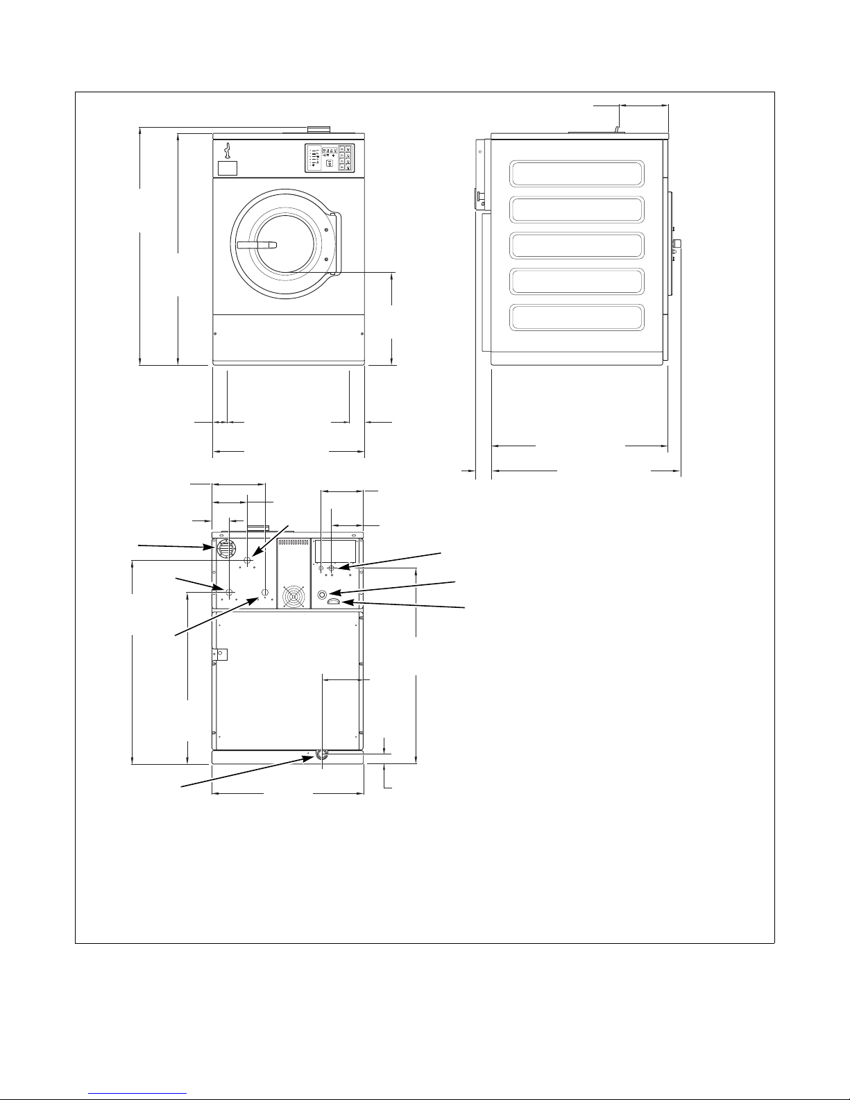
Specifications and Dimensions
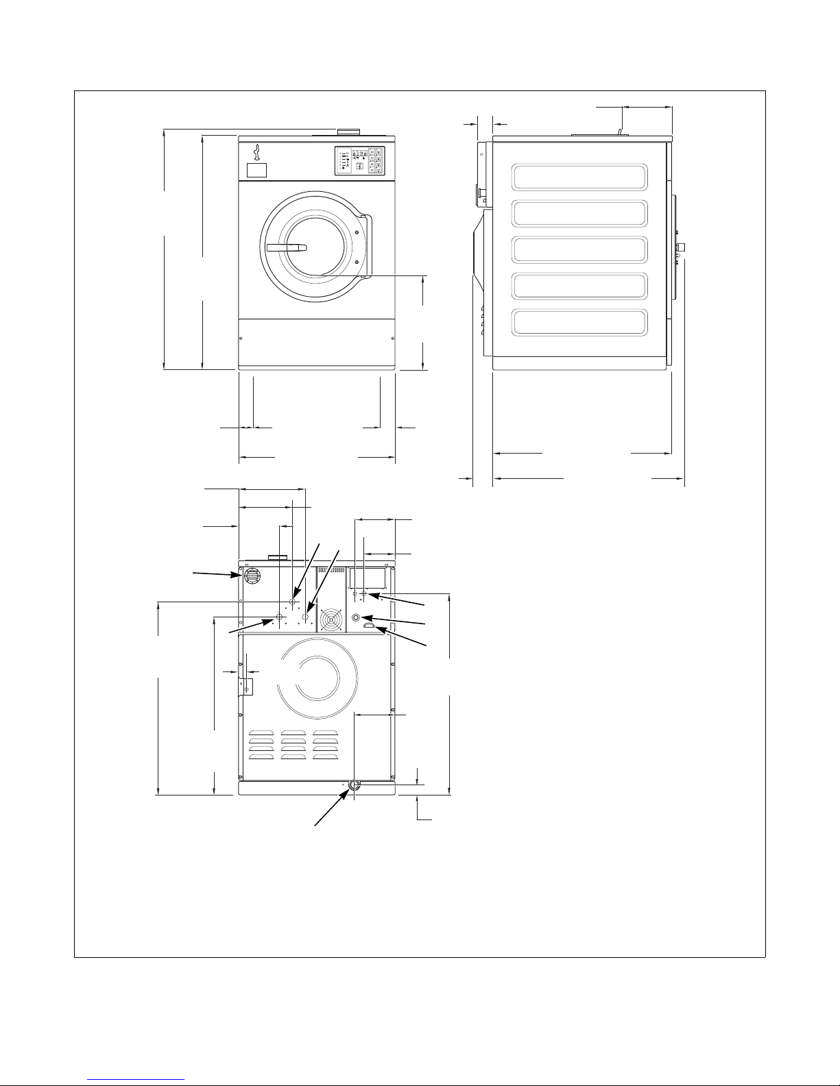
H
CFD513N
18 MODEL
1038 mm
(40.9 in.)
1011 mm
(39.8 in.)
660 mm (26 in.)
231 mm
(9.1 in.)
153 mm
(6 in.)
75 mm
(3 in.)
139 mm
(5.5 in.)
633 mm
(27.7 in.)
809 mm
(31.9 in.)
660 mm
(26 in.)
8
1
7
5
365 mm
(14.4 in.)
220 mm
(8.7 in.)
843 mm
(33.2 in.)
3
2
4
530 mm (20.9 in.)
70 mm
(2.8 in.)
180 mm
(7 in.)
184 mm
(7.2 in.)
65 mm
(2.6 in.)
65 mm
(2.6 in.)
69 mm
(2.7 in.)
670 mm (26.3 in.)
727 mm (28.6 in.)
6
1 Hot Water Connections 19 mm (.75 in.) 5 Drain Outlet
2 Power Input 6 Cold Water Inlet (required) 19 mm (.75 in.)
3 Emergency Stop Button 7 Cold Water Inlet (required) 19 mm (.75 in.)
4 Ventilation Tub 8 Fill and Supply Ventilation
Figure 1
CFD513N
9002062
© Copyright, Alliance Laundry Systems LLC – DO NOT COPY or TRANSMIT
9
Page 12
Specifications and Dimensions
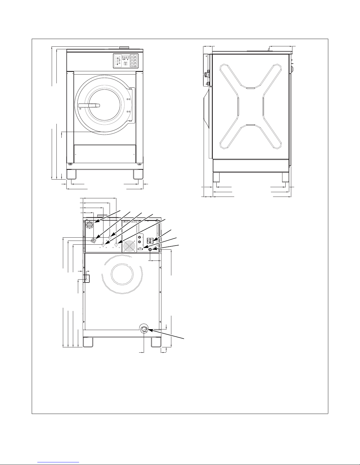
H
CFD514N
30 MODEL
1202 mm
(474 in.)
1175 mm
(46.3 in.)
780 mm (30.7 in.)
82 mm
(3.2 in.)
332 mm
(13.1 in.)
849 mm
(33.5 in.)
220 mm
(8.7 in.)
155 mm
(6.1 in.)
35 mm
(1.4 in.)
964 mm
(38 in.)
200 mm
(7.9 in.)
475 mm
(18.7 in.)
70 mm
(2.8 in.)
924 mm
(36.4 in.)
200 mm
(7.9 in.)
8
7
4
3
5
6
648 mm (25.5 in.)
88 mm
(3.5 in.)
760 mm (29.9 in.)
816 mm (32.1 in.)
66 mm
(2.6 in.)
66 mm
(2.6 in.)
202 mm
(8 in.)
267 mm
(10.5 in.)
1
2
1 Hot Water Connections 19 mm (.75 in.) 5 Ventilation Tub
2 Cold Water Inlet (required) 19 mm (.75 in.) 6 Drain Outlet
3 Power Input 7 Cold Water Inlet (required) 19 mm (.75 in.)
4 Emergency Stop Button 8 Fill and Supply Ventilation
Figure 2
CFD514N
10
© Copyright, Alliance Laundry Systems LLC – DO NOT COPY or TRANSMIT
9002062
Page 13
Specifications and Dimensions
CFD539N
CFD539N
H
CFD540N
1376 mm (54.15 in.)
1348 mm (53.07 in.)
472 mm (18.58 in.)
680 mm (26.77 in.)
50 mm
(1.97 in.)
780 mm (30.71 in.)
50 mm
(1.97 in.)
1141 mm (44.9 in.)
1108 mm (43.6 in.)
704 mm (27.7 in.)
185 mm (7.29 in.)
170 mm (6.69 in.)
3
2
1
665 mm (26.18 in.)
1066 mm (41.95 in.)
9
4
86.5 mm
(3.41 in.)
220 mm
(8.66 in.)
7
CFD537N
34 mm
(1.34 in.)
1015 mm (39.96 in.)
35 mm
(1.38 in.)
332 mm (13.05 in.)
267 mm (10.49 in.)
202 mm (7.93 in.)
109 mm
(4.3 in.)
CFD538N
6
5
33 MODEL
88 mm
(3.47 in.)
34 mm
(1.34 in.)
733 mm (28.86 in.)
753 mm (29.65 in.)
105 mm (4.13 in.)
8
CFD538N
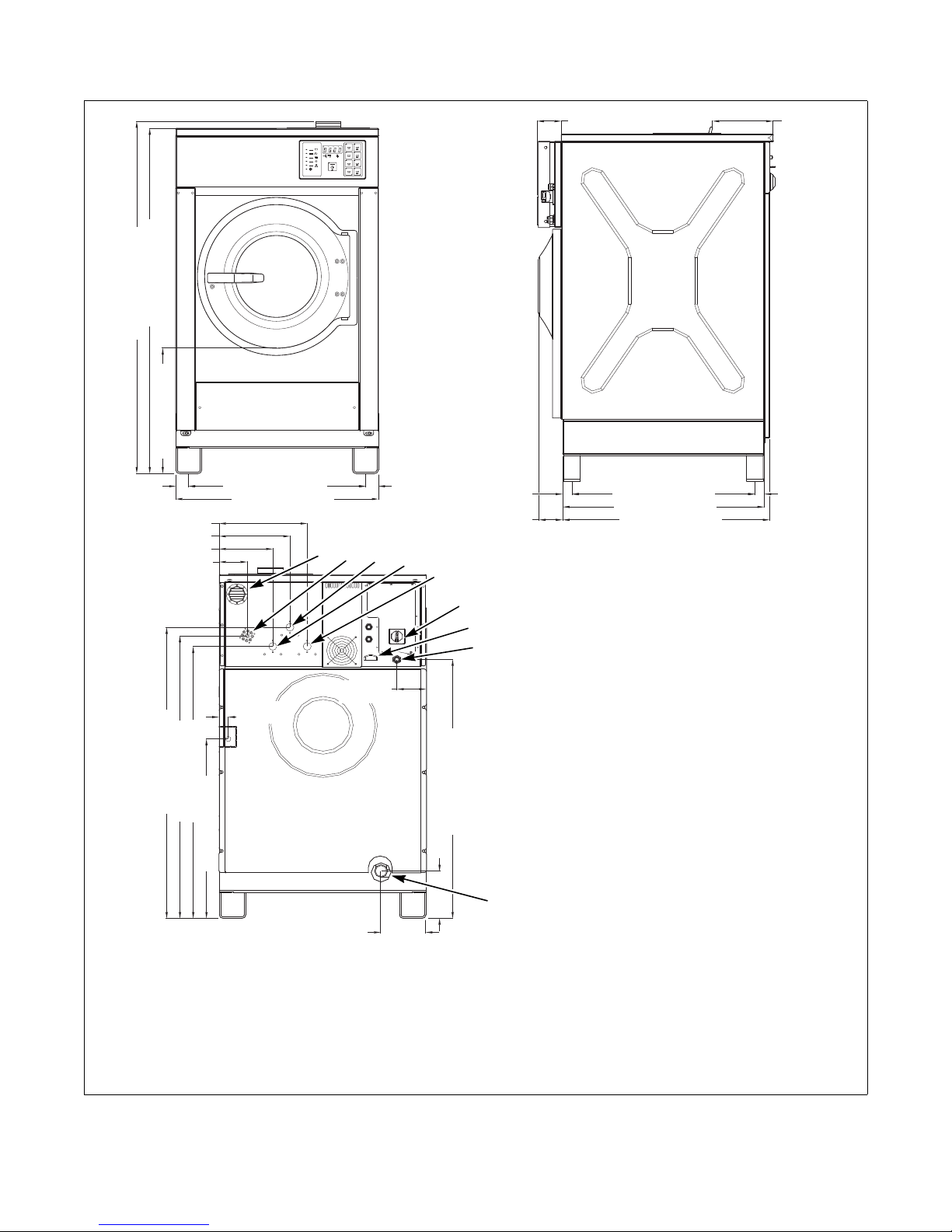
1 Fill and Supply Ventilation 6 Connection Clamps
2 External Liquid Supply Inlets 7 Electrical Power Inputs
3 Cold Water Inlet (Required) 8 Ventilation Tub
4 Cold Water Inlet (Required) 9 Drain Valve
5 Hot Water Inlet (Required)
9002062
© Copyright, Alliance Laundry Systems LLC – DO NOT COPY or TRANSMIT
Figure 3
11
Page 14
Specifications and Dimensions
CFD539N
CFD539N
H
CFD540N
1376 mm (54.15 in.)
1348 mm (53.07 in.)
472 mm (18.58 in.)
680 mm (26.77 in.)
50 mm
(1.97 in.)
780 mm (30.71 in.)
50 mm
(1.97 in.)
1141 mm (44.9 in.)
1108 mm (43.6 in.)
704 mm (27.7 in.)
185 mm (7.29 in.)
170 mm (6.69 in.)
3
2
1
765 mm (30.12 in.)
1066 mm (41.95 in.)
9
4
86.5 mm
(3.41 in.)
220 mm
(8.66 in.)
7
CFD537N
34 mm
(1.34 in.)
1015 mm (39.96 in.)
35 mm
(1.38 in.)
332 mm (13.05 in.)
267 mm (10.49 in.)
202 mm (7.93 in.)
109 mm
(4.3 in.)
CFD538N
6
5
40 MODEL
88 mm
(3.47 in.)
34 mm
(1.34 in.)
833 mm (32.8 in.)
853 mm (33.58 in.)
105 mm (4.13 in.)
8
CFD538N
1 Fill and Supply Ventilation 6 Connection Clamps
2 External Liquid Supply Inlets 7 Electrical Power Inputs
3 Cold Water Inlet (Required) 8 Ventilation Tub
4 Cold Water Inlet (Required) 9 Drain Valve
5 Hot Water Inlet (Required)
12
© Copyright, Alliance Laundry Systems LLC – DO NOT COPY or TRANSMIT
Figure 4
9002062
Page 15
Installation
Ensure that the machine is installed on a
level floor of sufficient strength and that
the recommended clearances for
inspection and maintenance are provided.
Never allow the inspection and
maintenance space to be blocked.
W488
CAUTION
Dimensional Clearances
Table 1 shows recommended minimum clearances on
all sides of the washer-extractor.
Recommended Minimum Clearances
Model 18 30 33 40
Minimum
rear
clearance
Minimum
clearance
between
machine
and wall
Minimum
clearance
between
machines
(side)
Minimum
front
clearance
(door swing)
600 mm
(24 in.)
150 mm
(6 in.)
25.4 mm
(1 in.)
419 mm
(16.5 in.)
600 mm
(24 in.)
150 mm
(6 in.)
25.4 mm
(1 in.)
419 mm
(16.5 in.)
Table 1
600 mm
(24 in.)
150 mm
(6 in.)
33 mm
(1.2 in.)
533 mm
(21 in.)
600 mm
(24 in.)
150 mm
(6 in.)
33 mm
(1.2 in.)
533 mm
(21 in.)
Machine Foundation
Thoroughness of detail must be stressed with all
foundation work to ensure a stable unit installation,
eliminating possibilities of excessive vibration during
extract.
The washer-extractor must be placed on a smooth
level surface so that the entire base of the machine is
supported and rests on the mounting surface.
The standard installation does not require anchoring
unless mandated by state or local codes.
Kinetic energy of the cylinder and dynamic loads on
the floor or foundation are shown in Table 2.
Table 2 can be used as a reference when designing
floors and foundations.
9002062
© Copyright, Alliance Laundry Systems LLC – DO NOT COPY or TRANSMIT
Floor Load Data
Model18303340
Kinetic
energy of
the
cylinder
Dynamic
bottom
load
1386 N/m 2592 N/m 2736 N/m 4105 N/m
700 N/16 Hz1000 N/
16 Hz
Table 2
1200 N/
16 Hz
1200 N/
16 Hz
13
Page 16
Installation
CFS485N
152 mm
(6 in.)
1
2
4
3
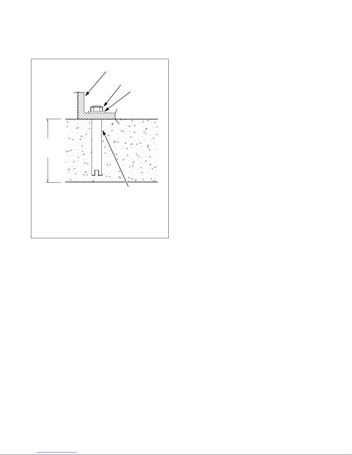
Mounting Bolt Installation
(If Required)
1 Base Frame
2 Bolt
3 Washer
4 Anchor Bolt/Plug
3. Put bolts through the machine in the anchors and
fasten them. For 18 and 30 models, the diameter
of the bolt must be minimum 1/2-13 or 12 mm.
For 33 and 40 models, the diameter of the bolt
must be minimum 5/8-11 or 16 mm.
4. To level machine, fill the spaces between the
machine base and floor with machinery grout.
Grout completely under all frame members.
Remove front and rear panels to gain access to all
frame members. Force grout under the machine
base until all voids are filled.
5. Remove the spacers carefully, allowing the
machine to settle into the wet grout.
6. Position washers and locknuts on machinery
anchor bolts and finger tighten to machine base.
7. After the grout is completely dry, tighten the
locknuts by even increments – one after the
other – until all are tightened evenly and the
machine is fastened securely to the floor.
CFS485N
Figure 5
After the concrete has cured and the anchors are
installed, proceed as follows:
1. Place the washer-extractor adjacent to the
foundation. Do not attempt to move it by pushing
on the sides. Always insert a pry bar or other
device under the bottom of the frame of the
washer-extractor to move it.
2. Place the washer-extractor carefully over the
anchors.
14
© Copyright, Alliance Laundry Systems LLC – DO NOT COPY or TRANSMIT
9002062
Page 17
Installation
The machine must never be activated
before removing the transport block.
W618
WARNING
1
CFD34N
1
18 AND 30 MODELS
1
FRONT
REAR
33 AND 40 MODELS
1
1
1
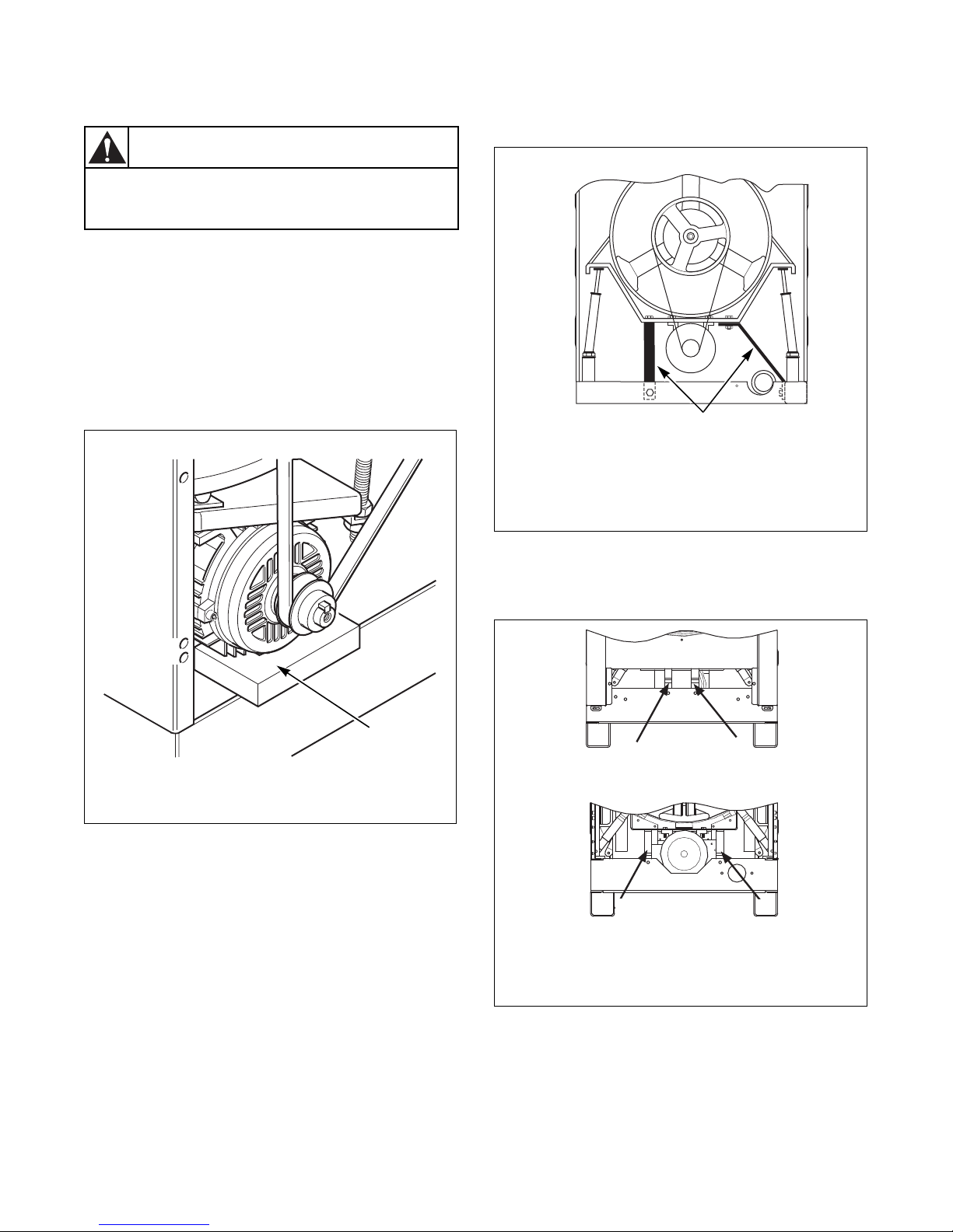
Removing the Transport Block
T o prevent damage during tran sportation, machine h as
been equipped with a transport block. To remove,
proceed as follows:
1. Place machine on level ground.
2. Remove service panels and back panel.
3. At rear of machine, lift at bottom of motor and
remove transport block if present. Refer to
Figure 6.
4. For 18 and 30 models, remove the panel braces.
Refer to Figure 7.
CFD34N
1 Panel Braces
Figure 7
CFD26N
CFD26N
1 Transport Block (Remove)
Figure 6
IMPORTANT: Do NOT lift motor by the pulley.
5. For 33 and 40 models, remove the transport
brackets. Refer to Figure 8.
CFD543N
1 Transport Brackets
Figure 8
6. Replace all panels removed.
9002062
© Copyright, Alliance Laundry Systems LLC – DO NOT COPY or TRANSMIT
15
Page 18
Installation
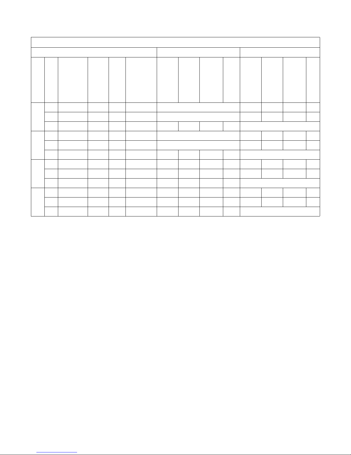
Electrical Specifications
Voltage Designation Standard Electric Heat
Model
Code
Voltage
Cycle
Phase
Wire
Full Load Amps
Circuit Breaker
Full Load Amps
Circuit Breaker
AWG/mm
kW
2
P 380-415 50/60 3 3+N+PE Not available 21 30 10/6.0 9
Q 200-240 50/60 3 3+PE Not available 27 30 10/6.0 9
18
X 200-240 50/60 1/3 2/3+PE 12 16 14/2.5 0.75 Not available
P 380-415 50/60 3 3+N+PE Not available 36 40 8/10.0 18
Q 200-240 50/60 3 3+PE Not available 49 60 6/16.0 18
30
X 200-240 50/60 1/3 2/3+PE 13 20 12/4.0 1.5 Not available
P 380-415 50/60 3 3+N+PE 18 20 12/4.0 1.5 44 50 8/10.0 18
Q 200-240 50/60 3 3+PE 18 20 12/4.0 1.5 63 70 4/25.0 18
33
X 200-240 50/60 1/3 2/3+PE 18 20 12/4.0 1.5 Not available
P 380-415 50/60 3 3+N+PE 18 20 12/4.0 1.5 44 50 8/10.0 18
Q 200-240 50/60 3 3+PE 18 20 12/4.0 1.5 63 70 4/25.0 18
40
X 200-240 50/60 1/3 2/3+PE 18 20 12/4.0 1.5 Not available
AWG/mm
kW
2
Table 3
16
© Copyright, Alliance Laundry Systems LLC – DO NOT COPY or TRANSMIT
9002062
Page 19
Operation
CHM482R
WASH
ADD
BLEACH
RINSE
SPIN
DOOR
NORMAL
NORMAL
QUICK AS QUICK WASH
HEAVY SOIL
DELICATE
RM RESS
PERM PRESS
HOT
WARM
HOT
HOT
WARM
COLD
WARM
COLD
START
PE P
WH
1
5
6
7
8
4
2
10
3
9
DOMESTIC MODELS
60C 60C
40C 40C
95C 95C
<
<
30C
CHM488R
1
5
6
7
8
4
11
2
3
9
INTERNA TIONAL MODELS
12
11
10
12
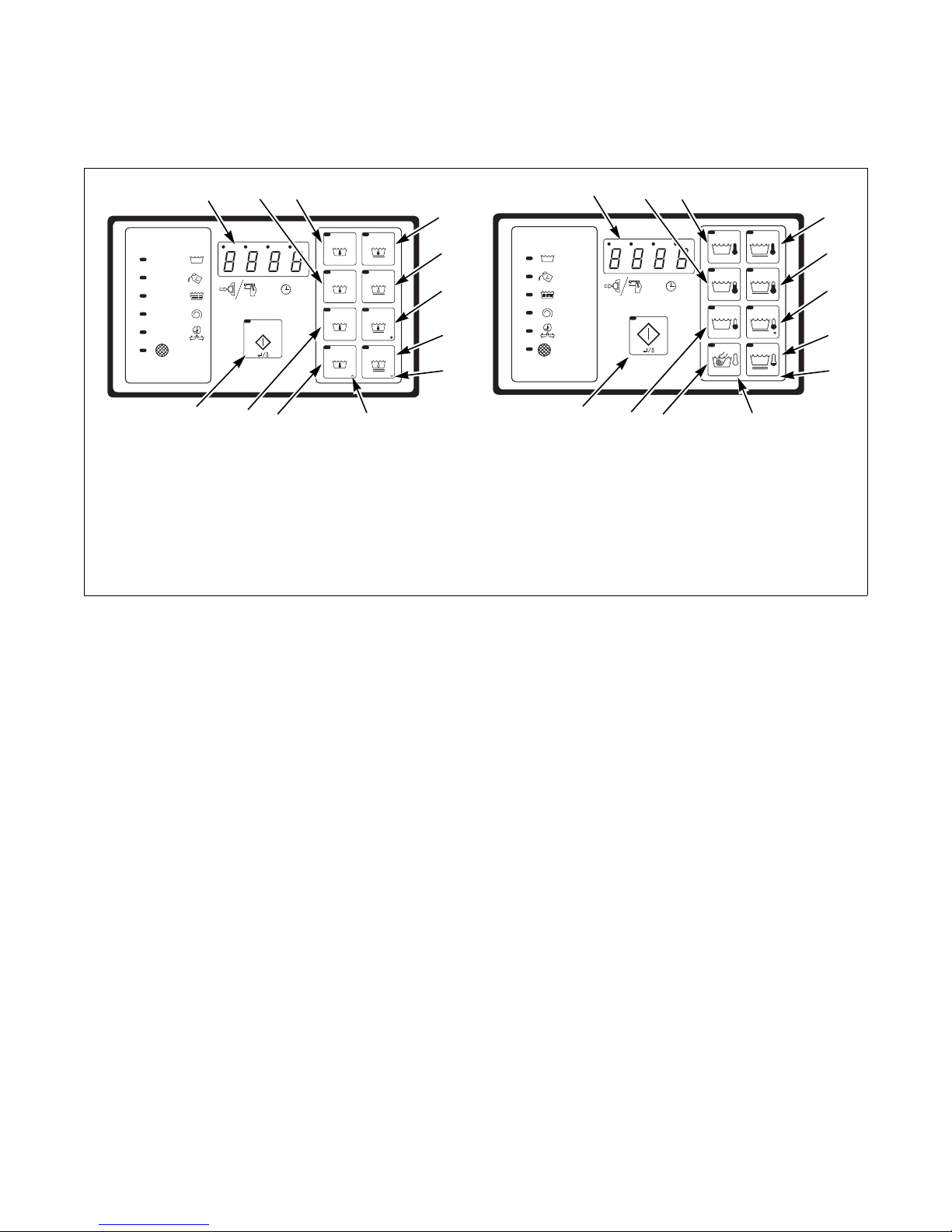
Control Panel
CHM482R CHM488R
1 Cycle 1 7 Cycle 7
2 Cycle 2 8 Cycle 8
3 Cycle 3 9 Down Edit/Change keypad
4 Cycle 4 10 Up Edit/Change keypad
5 Cycle 5 11 Start/Enter keypad
6 Cycle 6 12 Display
© Copyright, Alliance Laundry Systems LLC – DO NOT COPY or TRANSMIT
9002062
Figure 9
17
Page 20
Operation
CFD53N
CHM482R
WASH
ADD
BLEACH
RINSE
SPIN
DOOR
NORMAL
NORMAL
QUICK AS QUICK WASH
HEAVY SOIL
DELICATE
RM RESS
PERM PRESS
HOT
WARM
HOT
HOT
WARM
COLD
WARM
COLD
START
PE P
WH
DOMESTIC MODELS
60C 60C
40C 40C
95C 95C
<
<
30C
CHM488R
INTERNA TIONAL MODELS
Operating Instructions
1. Turn on main power source (circuit breaker).
2. Pull the door handle towards you to open the
door . Some models may have a door handle with
a button that must be pressed.
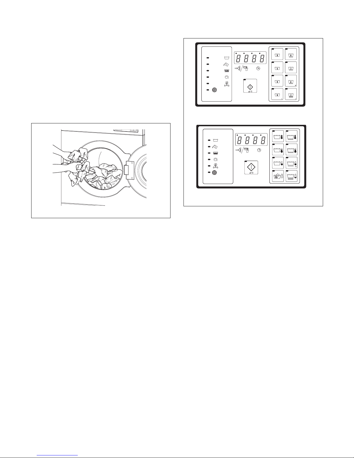
3. Load to capacity whenever possible. DO NOT
OVERLOAD. Refer to Figure 10.
NOTE: Underloading can cause out-of-balance
conditions that can shorten machine life.
CHM482R
CFD53N
Figure 10
4. Close door by pushing door handle towards
machine.
5. The default wash cycle will display.
NOTE: Perm Press Cold is the default cycle for
coin models if none is selected.
CHM488R
Figure 11
6. If desired, select a different cycle at this point
before satisfying vend. The LED indicator for
that cycle will light.
18
© Copyright, Alliance Laundry Systems LLC – DO NOT COPY or TRANSMIT
9002062
Page 21
Operation
1
2
3
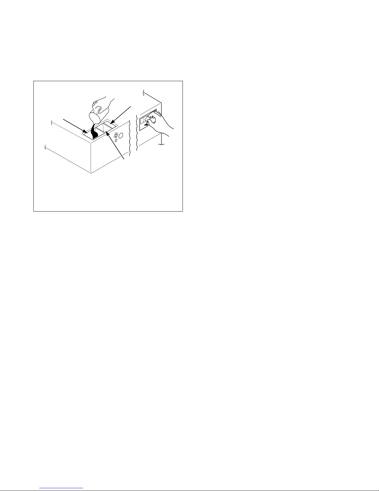
7. Add liquid and/or powder supplies to supply
dispenser. Refer to Figure 12.
a. Add detergent to compartment 1.
b. Add softener to compartment 3.
1 Detergent
2 Bleach
3 Softener
Figure 12
8. Add coins to machine. As each coin is added, the
vend counts down to the amount remaining.
Refer to Figure 12.
9. When applicable, add bleach to compartment 2
when the ADD BLEACH LED is lit.
10. Press the desired wash cycle keypad.
11. Press the START keypad and the active cycle
remains the chosen wash cycle.
12. When cycle is complete, display shows “donE”.
B157R
9002062
© Copyright, Alliance Laundry Systems LLC – DO NOT COPY or TRANSMIT
19
Page 22
Disposal of Unit
This appliance is marked according to the European
directive 2002/96/EC on Waste Electrical and
Electronic Equipment (WEEE).
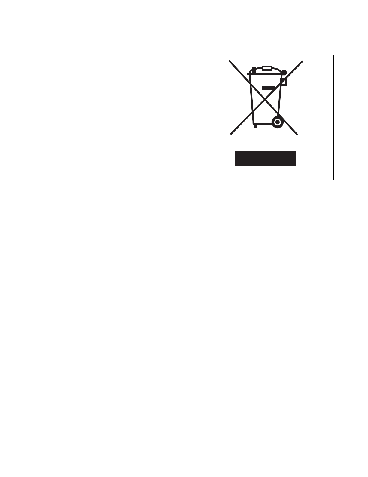
This symbol on the product or on its packaging
indicates that this product shall not be treated as
household waste. Refer to Figure 13. Instead it shall
be handed over to the applicable collection point for
the recycling of electrical and electronic equipment.
Ensuring this product is disposed of correctly will help
prevent potential negative consequences for the
environment and human health which could otherwise
be caused by inappropriate waste handling of this
product. The recycling of materials will help to
conserve natural resources. For more detailed
information about recycling of this product, please
contact the local city office, household waste disposal
service, or the source from which the product was
purchased.
MIX1N
Figure 13
20
© Copyright, Alliance Laundry Systems LLC – DO NOT COPY or TRANSMIT 9002062
 Loading...