

Alliance Laundry Systems LWB19BL-1109, LWS02A, LWS02B, LWS02M, LWS11A-3062 Service Manual
...
Home
Automatic
Washers
Refer to Page 5 for Model Numbers
Service
www.comlaundry.com
W424SE1A
Part No. 39311R3
November 2001


Table of Contents
Section 1 – Safety Information............................3
Locating an Authorized Servicer .............................4
Section 2 – Introduction
Model Identification.................................................5
How Your Washer Works........................................8
Customer Service...................................................10
Nameplate Location...............................................10
Section 3 – Troubleshooting
1. No Hot Water...................................................11
2. No Cold Water.................................................11
3. No Warm Water...............................................12
4. Water Fill Does Not Stop At Proper Level......12
5. Timer Does Not Advance................................13
6. Motor Does Not Run .......................................14
7. No Agitation ....................................................15
8. Constant Agitation...........................................15
9. Washer Overheats, Cycles On Motor Thermal
Protector, Switch Actuator Kicks In
And Out............................................................16
10. Slow Spin Or No Spin .....................................16
11. Constant Spin...................................................17
12. Washer Stops In Cycle; Quits After A Couple
Loads; Is Intermittent.......................................17
13. Washer Is Locked Up Or Binding ...................17
14. Outer Tub Does Not Empty.............................18
15. Excessive Vibration.........................................18
16. Water Leaking From Outer Tub......................18
Section 4 – Grounding
17. Wall Receptacle Polarity Check ......................19
18. Power Cord to Connection Block, Connection
Block to Control Hood Rear Panel; Models with
Suffixes B3069, 3050 and 3062.......................20
19. Power Cord To Cabinet Top, Cabinet Top To
Control Hood Mounting Bracket, Pressure
Switch Mounting Bracket And Ground Tab On
Graphic Panel...................................................21
20. Control Hood Wire Harness To Top Left Rear
Corner Gusset Of Cabinet................................22
21. Wire Harness to Motor ....................................23
Section 5 – Service Procedures
22. Control Hood Assembly ..................................25
23. Timer................................................................30
24. Temperature Switch.........................................32
25. Pressure Switch................................................32
26. Graphic Panel...................................................32
27. Loading Door...................................................33
28. Agitator............................................................34
29. Agitator, Drive Bell And Seal Assembly ........34
30. Front Panel.......................................................38
31. Motor And Mounting Bracket .........................39
32. Idler Lever And Pulley ....................................43
33. Motor Switch ...................................................44
34. Pump Assembly (Electric Pump Models) .......45
35. Cabinet Top Assembly ....................................47
36. Door Switch.....................................................48
37. Mixing Valve Assembly..................................49
38. Washtub And Balance Ring.............................50
39. Hub And Seal Kit Assembly ...........................54
40. Outer Tub.........................................................58
41. Drive Pulley, Helix And Brake........................61
42. Weldment And Bearing Assembly..................65
43. Transmission Assembly...................................67
44. Upper Bearing Assembly.................................73
45. Friction Ring....................................................74
Section 6 – Adjustments
46. Leveling Legs ..................................................77
47. Pressure Switch................................................78
48. Belt (Agitate And Spin)...................................78
Section 7 – Test Procedures
49. Motor Test Procedure......................................79
50. Mixing Valve Solenoid Test Procedure...........80
51. Temperature Switch Test Procedure................80
Section 8 – Cycle Sequence Charts
Timer No. 37925 Cycle Sequence..........................81
Timer No. 37927 Cycle Sequence..........................82
Timer No. 37928 Cycle Sequence..........................83
Timer No. 37929 Cycle Sequence..........................84
Timer No. 37930 Cycle Sequence..........................85
Timer No. 37931 Cycle Sequence..........................86
Timer No. 37995 Cycle Sequence..........................87
Timer No. 39445 Cycle Sequence..........................88
Section 9 – Internal Wiring of Washer Motor
Switch
Motor Assembly (1 Speed Motors).........................89
Motor Assembly (2 Speed Motors).........................90
© Copyright 2001, Alliance Laundry Systems LLC
All rights reserved. No part of the contents of this book may be reproduced or transmitted in any form or by any means without
the expressed written consent of the publisher.
39311 1
© Copyright, Alliance Laundry Systems LLC – DO NOT COPY or TRANSMIT

Notes
2 39311
© Copyright, Alliance Laundry Systems LLC – DO NOT COPY or TRANSMIT

Section 1
Safety Information
Throughout this manual and on machine decals, you will find precautionary statements (“CAUTION,”
“WARNING,” and “DANGER”) followed by specific instructions. These precautions are intended for the personal
safety of the operator, user, servicer and those maintaining the machine.
a DANGER
Danger indicates the presence of a hazard that will cause severe personal injury, death or substantial property
damage if the danger is ignored.
a WARNING
Warning indicates the presence of a hazard that can cause severe personal injury, death or substantial property
damage if the warning is ignored.
a CAUTION
Caution indicates the presence of a hazard that will or can cause minor personal injury or property damage if the
caution is ignored.
Additional precautionary statements (“IMPORTANT” and “NOTE”) are followed by specific instructions.
IMPORTANT
The word “IMPORTANT” is used to inform the reader of specific procedures where minor machine damage will
occur if the procedure is not followed.
NOTE
The word “NOTE” is used to communicate installation, operation, maintenance or servicing information that is
important but not hazard related.
In the interest of safety, some general precautions relating to the operation of this machine follow.
WARNING
• Failure to install, maintain and/or operate this product according to the manufacturer’s
instructions may result in conditions which can produce serious injury, death and/or property
damage.
• Do not repair or replace any part of the product or attempt any servicing unless specifically
recommended or published in this Service Manual and that you understand and have the
skills to carry out.
• Whenever ground wires are removed during servicing, these ground wires must be
reconnected to ensure that the product is properly grounded and to reduce the risk of fire,
electric shock, serious injury or death.
W006R1
39311 3
© Copyright, Alliance Laundry Systems LLC – DO NOT COPY or TRANSMIT
Section 1 Safety Information
WARNING
To reduce the risk of electric shock, fire, explosion, serious injury or death:
• Disconnect electric power to the washer before servicing.
• Never start the washer with any guards/panels removed.
• Whenever ground wires are removed during servicing, these ground wires must be
reconnected to ensure that the washer is properly grounded.
WARNING
Repairs that are made to your products by unqualified persons can result in hazards due to
improper assembly or adjustments subjecting you, or the inexperienced person making such
repairs, to the risk of serious injury, electrical shock or death.
WARNING
W003
W007
If you or an unqualified person perform service on your product, you must assume the
responsibility for any personal injury or property damage which may result. The manufacturer
will not be responsible for any injury or property damage arising from improper service and/or
service procedures.
W008
NOTE: The WARNINGS and IMPORTANT INSTRUCTIONS appearing in this manual are not meant to
cover all possible conditions and situations that may occur. Common sense, caution and care must be
exercised when installing, maintaining or operating the washer.
Always contact your dealer, distributor, service agent or the manufacturer about any problems or conditions you do
not understand.
Locating an Authorized Servicer
Alliance Laundry Systems is not responsible for personal injury or property damage resulting from improper
service. Review all service information before beginning repairs.
Warranty service must be performed by an authorized technician, using authorized factory parts. If service is
required after the warranty expires, Alliance Laundry Systems also recommends contacting an authorized
technician and using authorized factory parts.
4 39311
© Copyright, Alliance Laundry Systems LLC – DO NOT COPY or TRANSMIT

Section 2
Introduction
Model Identification
Information in this manual is applicable to these washer models.
Model
Number
LWB19A*-1109 X 3.3
LWB19B*-1109 X 3.3
LWB19M*-1109 X 3.3
LWG74A*-3050 X 3.3
LWK24A*-3050 X 3.3
LWK74A*-3050 X 3.3
LWK23A*-3050 X 3.3
LWK73A*-3050 X 3.3
LWH18A*-3322 X 3.3
LWS01A* X 2.9
LWS01A*C X 2.9
LWS01A*-1000 X 2.9
LWS01A*-1088 X 2.9
LWS01A
LWS01A*-3300 X 2.9
LWS01B* X 2.9
LWS01M* X 2.9
LWS01M*-1000 X 2.9
LWS01M*-3088 X 2.9
LWS01M*-3300 X 2.9
LWS02A* X 3.3
LWS02B* X 3.3
LWS02M* X 3.3
LWS11A*-3062 X 3.3
LWS16A* X 3.3
LWS16A*K X 3.3
LWS16B* X 3.3
LWS16B*K X 3.3
LWS16M* X 3.3
LWS16A*-1000 X 3.3
LWS16M*-1000 X 3.3
LWS16A*-3000 X 3.3
* Add Letter To Designate Color. L – Almond W – White
*-3088 X 2.9
1 Speed
Motor
2 Speed
Motor
3 Speed
Motor
Porcelain Washtub
(cu. ft.)
Stainless Steel
Washtub (cu. ft.)
(continued)
39311 5
© Copyright, Alliance Laundry Systems LLC – DO NOT COPY or TRANSMIT

Section 2 Introduction
Model
Number
1 Speed
Motor
2 Speed
Motor
3 Speed
Motor
Porcelain Washtub
(cu. ft.)
Stainless Steel
Washtub (cu. ft.)
LWS16M*-3000 X 3.3
LWS16A*-3022 X 3.3
LWS16M*-3022 X 3.3
LWS16A*-3300 X 3.3
LWS16M*-3300 X 3.3
LWS16A*-3322 X 3.3
LWS16M*-3322 X 3.3
LWS16M*K X 3.3
LWS17A* X 3.3
LWS17A*K X 3.3
LWS17B* X 3.3
LWS17B*K X 3.3
LWS17M* X 3.3
LWS17A*-1000 X 3.3
LWS17M*-1000 X 3.3
LWS17A*-3000 X 3.3
LWS17M*-3000 X 3.3
LWS17A*-3022 X 3.3
LWS17M*-3022 X 3.3
LWS17A*-3028 X 3.3
LWS17A*-3050 X 3.3
LWS17M*-3050 X 3.3
LWS17A*-3300 X 3.3
LWS17M*-3300 X 3.3
LWS17A*-3322 X 3.3
LWS17M*-3322 X 3.3
LWS17A*B3020 X 3.3
LWS17M*B3020 X 3.3
LWS17A*B3069 X 3.3
LWS17M*B3069 X 3.3
LWS17M*K X 3.3
LWS21A*-3062 X 3.3
LWS42M*-3050 X 3.3
LWS45A* X 3.3
LWS45B* X 3.3
LWS45M* X 3.3
LWY17A*-1109 X 3.3
LWY17B*-1109 X 3.3
LWY17M*-1109 X 3.3
* Add Letter To Designate Color. L – Almond W – White
6 39311
© Copyright, Alliance Laundry Systems LLC – DO NOT COPY or TRANSMIT

Section 2 Introduction
Model
Number
1 Speed
Motor
2 Speed
Motor
3 Speed
Motor
Porcelain Washtub
(cu. ft.)
Stainless Steel
Washtub (cu. ft.)
LWY45A*-1109 X 3.3
LWY45B*-1109 X 3.3
LWY45M*-1109 X 3.3
LWZ01M*-1102 X 2.9
LWZ16A*-1000 X 3.3
LWZ16M*-1000 X 3.3
LWZ17A*-3000 X 3.3
LWZ17M*-3000 X 3.3
LWZ17A*B3020 X 3.3
LWZ17M*B3020 X 3.3
LWZ17A*B3069 X 3.3
LWZ17M*B3069 X 3.3
LWZ22M*-1102 X 3.3
LWZ42M*-1102 X 3.3
LWZ52M*-1102 X 3.3
LWZ77M*-1102 X 3.3
* Add Letter To Designate Color. L – Almond W – White
39311 7
© Copyright, Alliance Laundry Systems LLC – DO NOT COPY or TRANSMIT
Section 2 Introduction
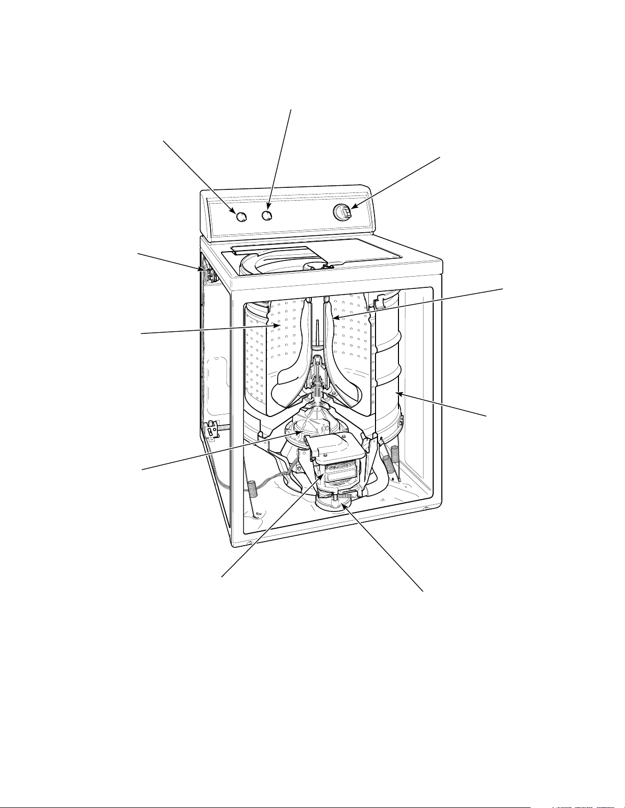
How Your Washer Works
PRESSURE
SWITCH
TEMPERATURE
SWITCH
MIXING
VALVE
WASHTUB
TIMER
AGITATOR
TRANSMISSION
MOTOR
PUMP
OUTER
TUB
W407SE3A
8 39311
© Copyright, Alliance Laundry Systems LLC – DO NOT COPY or TRANSMIT

Section 2 Introduction
The cycle begins with a wash fill. The water
temperature is determined by the temperature selector.
While water fills the washtub, a column of air is
trapped in a pressure bulb and hose. The air pressure
continues to increase as the washtub fills with water
until it is great enough to activate the pressure switch.
The pressure switch then causes the wash fill to stop
and wash agitation to begin. However, the loading door
must be closed for the washer to agitate or spin.
The washer uses a reversing type motor, a special drive
belt and an idler assembly. The idler assembly applies
tension to the outside of the drive belt.
During agitation, the motor runs in the
counterclockwise direction. The spring tension on the
idler pulley applies the tension required to reduce the
slack on the drive belt and maintain maximum belt to
motor pulley contact. This eliminates belt slippage and
ensures an efficient wash action, even with extra large
loads.
The belt drives the transmission drive pulley in the
counterclockwise direction. The pulley drives the helix
which is splined to the input shaft of the transmission.
This causes the input shaft to turn inside of a roller
clutch which is pressed into the transmission cover.
This roller clutch acts as a bearing in the
counterclockwise direction allowing the transmission
gears to operate. The transmission’s rack and pinion
gear design produces a 210 degree agitation stroke at
the output shaft of the transmission which drives the
agitator. The brake assembly remains locked during the
agitation mode since no pressure is applied to it by the
transmission drive pulley.
As water is removed by the pump and the momentum
of the washtub increases, the idler spring tension
gradually overcomes the belt tension removing the belt
slack. This eventually increases the belt to pulley
contact until maximum spin speed is achieved.
The drive pulley turns clockwise riding up the ramps of
the helix, exerting pressure on the brake and forcing it
to release from brake pads. The helix drives the input
shaft of the transmission, and when the input shaft turns
in the clockwise direction the roller clutch locks onto
the shaft causing the entire transmission assembly to
turn. None of the gears in the transmission are
operating at this time. The hub of the washtub is splined
to the transmission tube and rotates with the
transmission assembly. The centrifugal force created
by the spinning washtub causes water to be extracted
from the clothes.
Water is introduced during the first spin to “SPRAY”
the garments and remove suds from them. The initial
spin is followed by rinse agitation to rinse away any
detergent residue. The washer fills and then agitates
like the wash portion of the cycle. Following rinse
agitation, a final spin extracts the rinse water from the
clothes preparing them for the dryer.
After the wash agitation is completed, the timer
advances into the first spin. During spin, the motor
reverses turning in the clockwise direction to spin the
water out of the washtub. The combination of water,
washtub and load weight cause the drive belt tension on
the idler side of the belt to overtake the idler spring
pressure allowing the belt to become slack on the
opposite side. This reduces the belt to pulley contact
and allows slipping between the belt and pulley.
39311 9
© Copyright, Alliance Laundry Systems LLC – DO NOT COPY or TRANSMIT
Section 2 Introduction
Customer Service
If literature or replacement parts are required, contact
the source from whom the machine was purchased or
contact Alliance Laundry Systems at (920) 748-3950
for the name and address of the nearest authorized
parts distributor.
For technical assistance, call (920) 748-3121.
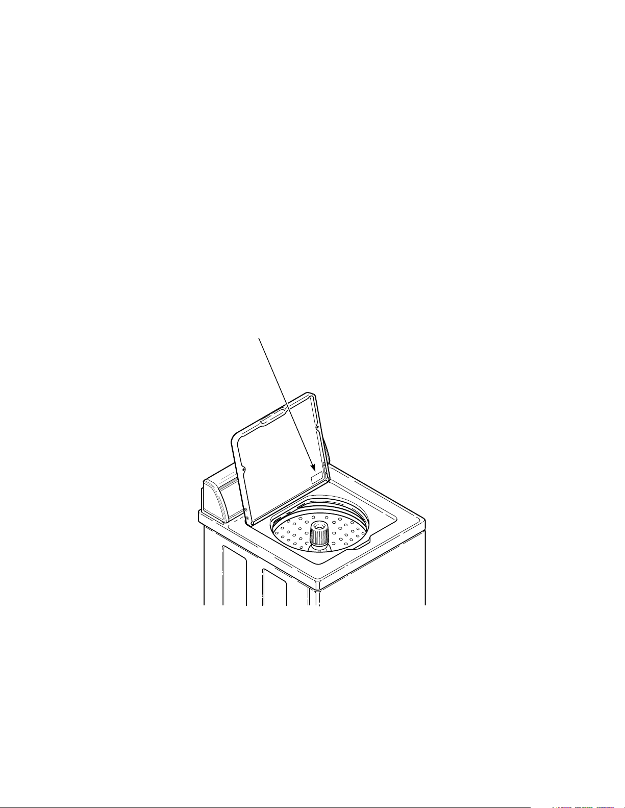
Nameplate Location
When calling or writing about your product, be sure to
mention model and serial numbers. Model and serial
numbers are located on nameplate(s) as shown.
W429SE1B
10 39311
© Copyright, Alliance Laundry Systems LLC – DO NOT COPY or TRANSMIT
Section 3
Troubleshooting
WARNING
To reduce the risk of electric shock, fire, explosion, serious injury or death:
• Disconnect electric power to the washer before servicing.
• Never start the washer with any guards/panels removed.
• Whenever ground wires are removed during servicing, these ground wires must be
reconnected to ensure that the washer is properly grounded.
IMPORTANT: Refer to Wiring Diagram for aid in testing washer components.
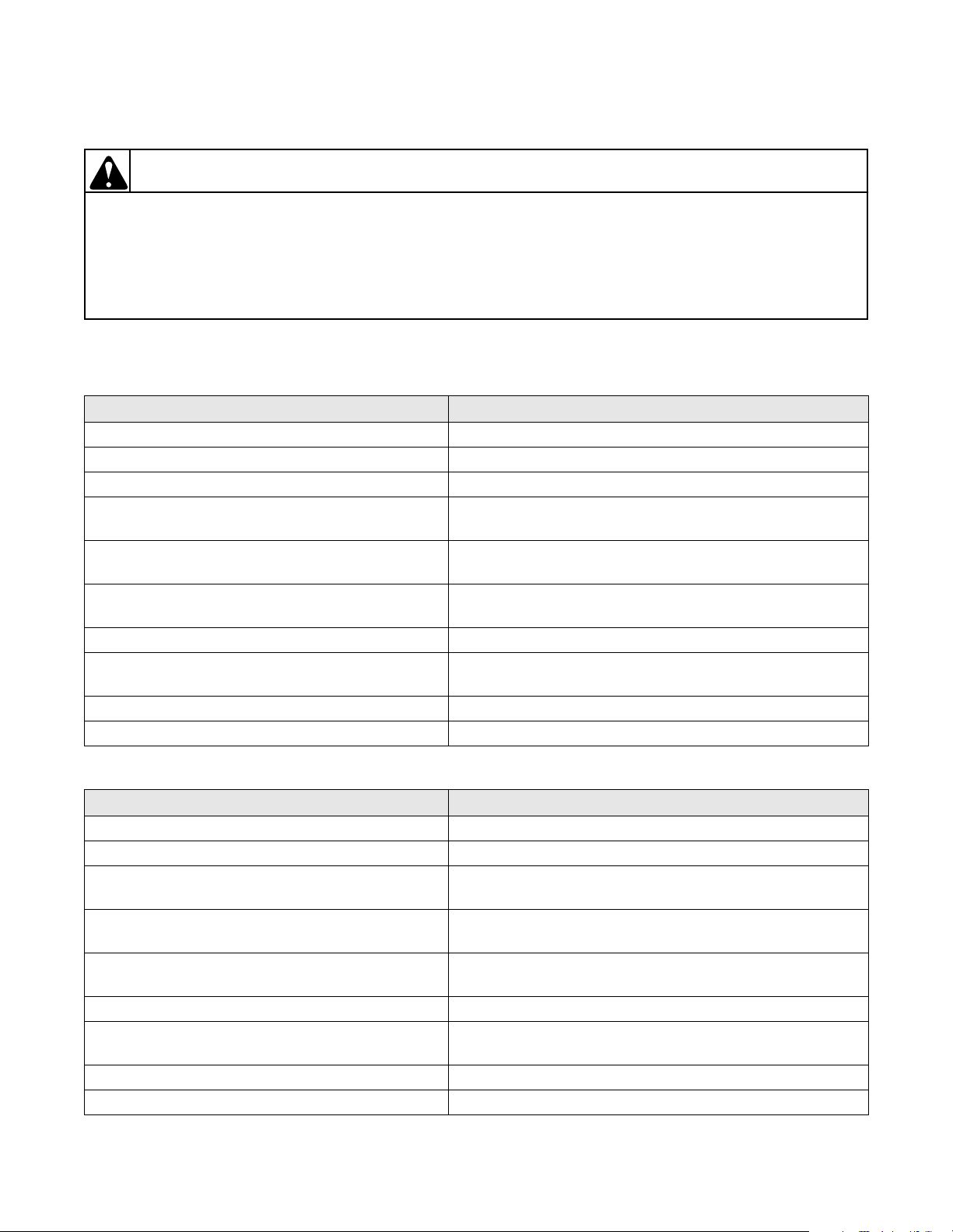
1. NO HOT WATER
POSSIBLE CAUSE TO CORRECT
Hot water supply faucet is closed. Open faucet.
Water supply is cold. Check water heater.
Kinked hot water inlet hose. Straighten or replace hose.
Clogged mixing valve screen, or screen in outer end
of inlet hose nearest water supply faucet.
Inoperative hot water mixing valve solenoid. Test solenoid. Refer to Paragraph 50. Replace valve if
Inoperative timer. Test for continuity through timer circuits. Refer to wiring
Inoperative temperature switch. Test switch. Refer to Paragraph 51. Replace if inoperative.
Inoperative pressure switch. Test switch. Must have continuity from terminal 1 to 2 when
Clogged pressure hose. Remove and clean or replace hose.
Broken, loose or incorrect wiring. Refer to wiring diagram.
Disconnect hot water inlet hose, and clean or replace screen.
solenoid is inoperative.
diagram. Replace if inoperative.
empty or 1-3 when full. Replace if inoperative.
W003
2. NO COLD WATER
POSSIBLE CAUSE TO CORRECT
Cold water supply faucet is closed. Open faucet.
Kinked cold water inlet hose. Straighten or replace hose.
Clogged mixing valve screen, or clogged screens in
outer end of inlet hose nearest water supply faucet.
Inoperative cold water mixing valve solenoid. Test solenoid. Refer to Paragraph 50. Replace valve if
Inoperative timer. Test for continuity through timer circuits. Refer to wiring
Inoperative temperature switch. Test switch. Refer to Paragraph 51. Replace if inoperative.
Inoperative pressure switch. Test switch. Must have continuity from terminal 1 to 2 when
Clogged pressure hose. Remove and clean or replace hose.
Broken, loose or incorrect wiring. Refer to wiring diagram.
39311 11
© Copyright, Alliance Laundry Systems LLC – DO NOT COPY or TRANSMIT
Disconnect cold water inlet hose, and clean or replace
screen.
solenoid is inoperative.
diagram. Replace if inoperative.
empty or 1-3 when full. Replace if inoperative.
Section 3 Troubleshooting
WARNING
To reduce the risk of electric shock, fire, explosion, serious injury or death:
• Disconnect electric power to the washer before servicing.
• Never start the washer with any guards/panels removed.
• Whenever ground wires are removed during servicing, these ground wires must be
reconnected to ensure that the washer is properly grounded.
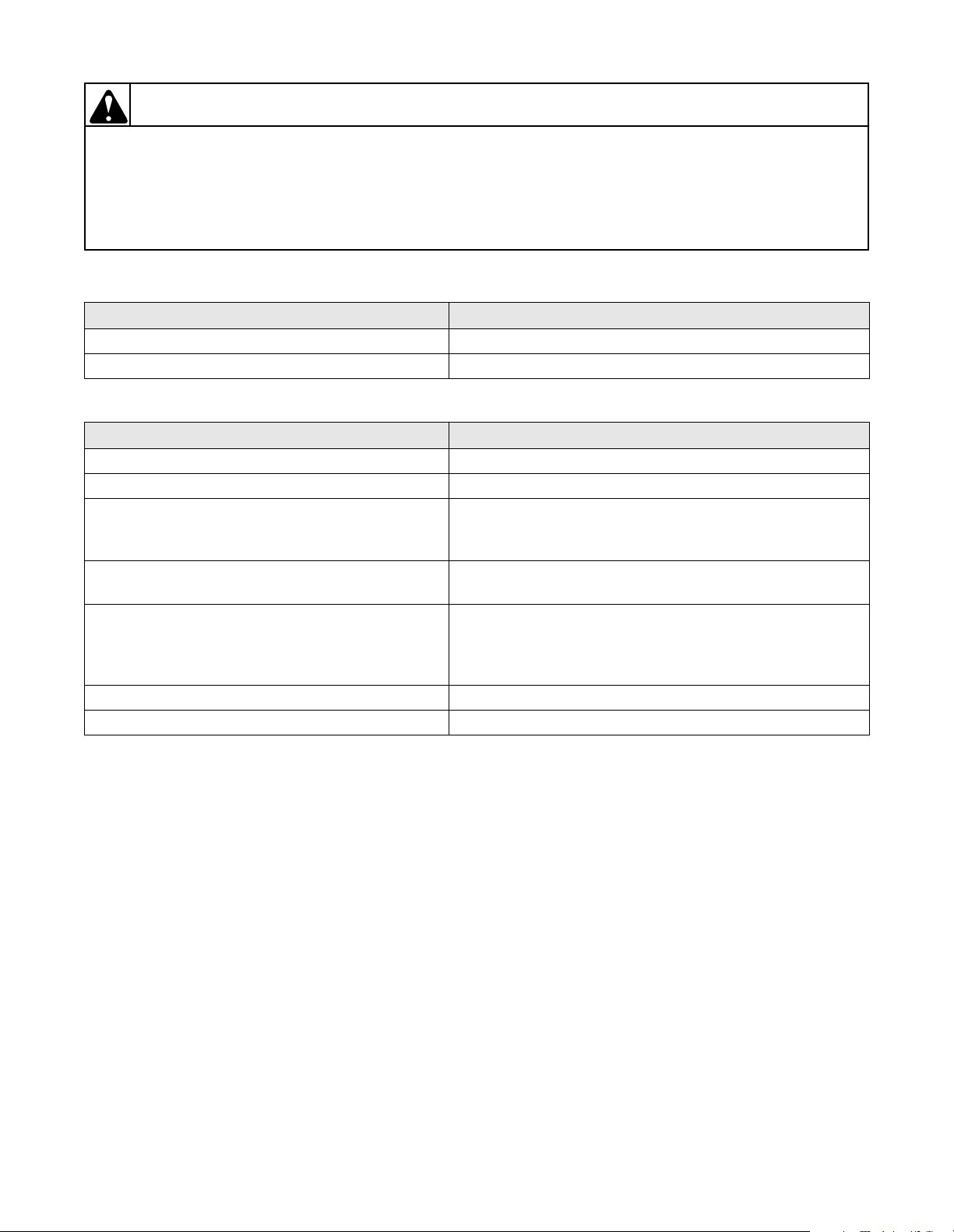
3. NO WARM WATER
POSSIBLE CAUSE TO CORRECT
No hot water. Refer to Paragraph 1.
No cold water. Refer to Paragraph 2.
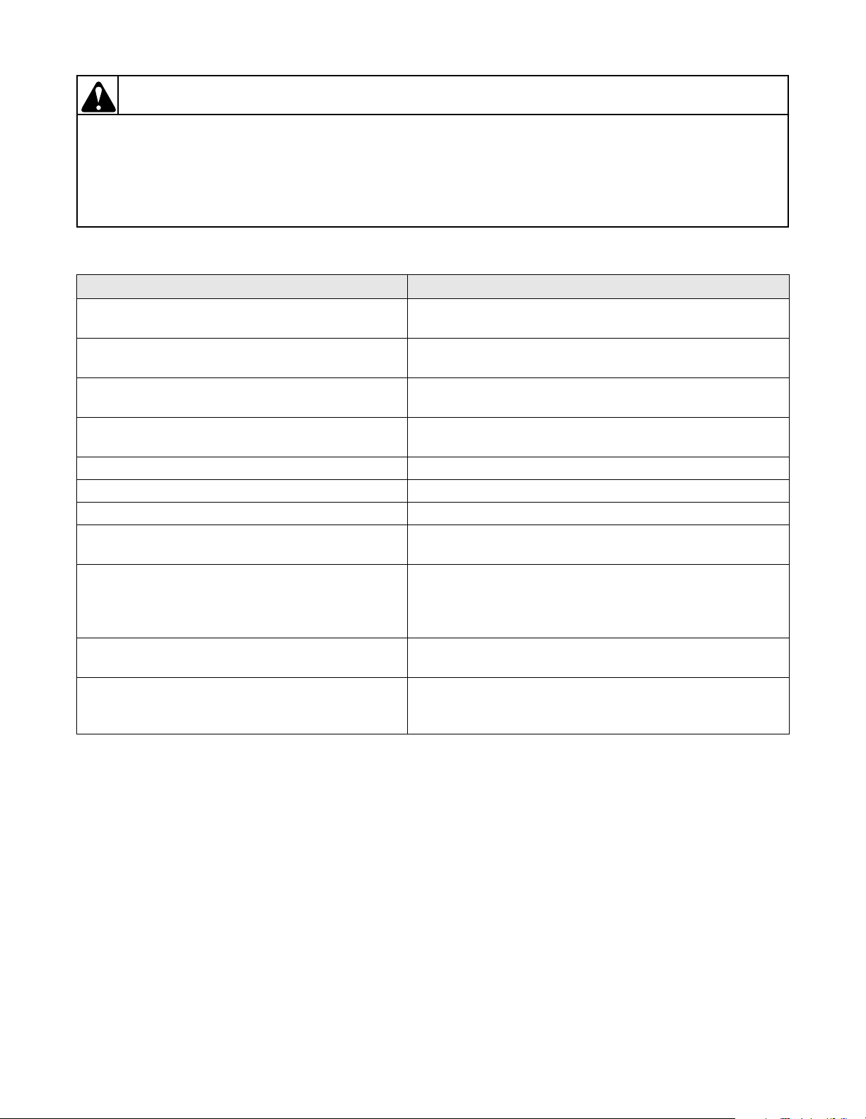
4. WATER FILL DOES NOT STOP AT PROPER LEVEL
POSSIBLE CAUSE TO CORRECT
Inoperative pressure switch. Test switch. Refer to Paragraph 47. Replace if inoperative.
Air leak in pressure hose. Replace hose.
Sediment on or under mixing valve diaphragm,
defective diaphragm, or armature binding in
armature guide.
Broken, weak or missing mixing valve armature
spring.
A siphoning action started in washer will cause
water to be siphoned from washer during cycle due
to end of drain hose being lower than cabinet top of
washer. Drain hose fits tight in standpipe or drain.
Water in pressure hose. Blow air through hose to remove water or replace hose.
Broken, loose, shorted or incorrect wiring. Refer to wiring diagram.
Replace valve.
Replace valve.
Install No. 562P3 Siphon Break Kit. Provide an air gap
around drain hose and drain receptacle. Install No. 36878
Standpipe Adapter (optional on some models).
W003
12 39311
© Copyright, Alliance Laundry Systems LLC – DO NOT COPY or TRANSMIT
Section 3 Troubleshooting
WARNING
To reduce the risk of electric shock, fire, explosion, serious injury or death:
• Disconnect electric power to the washer before servicing.
• Never start the washer with any guards/panels removed.
• Whenever ground wires are removed during servicing, these ground wires must be
reconnected to ensure that the washer is properly grounded.
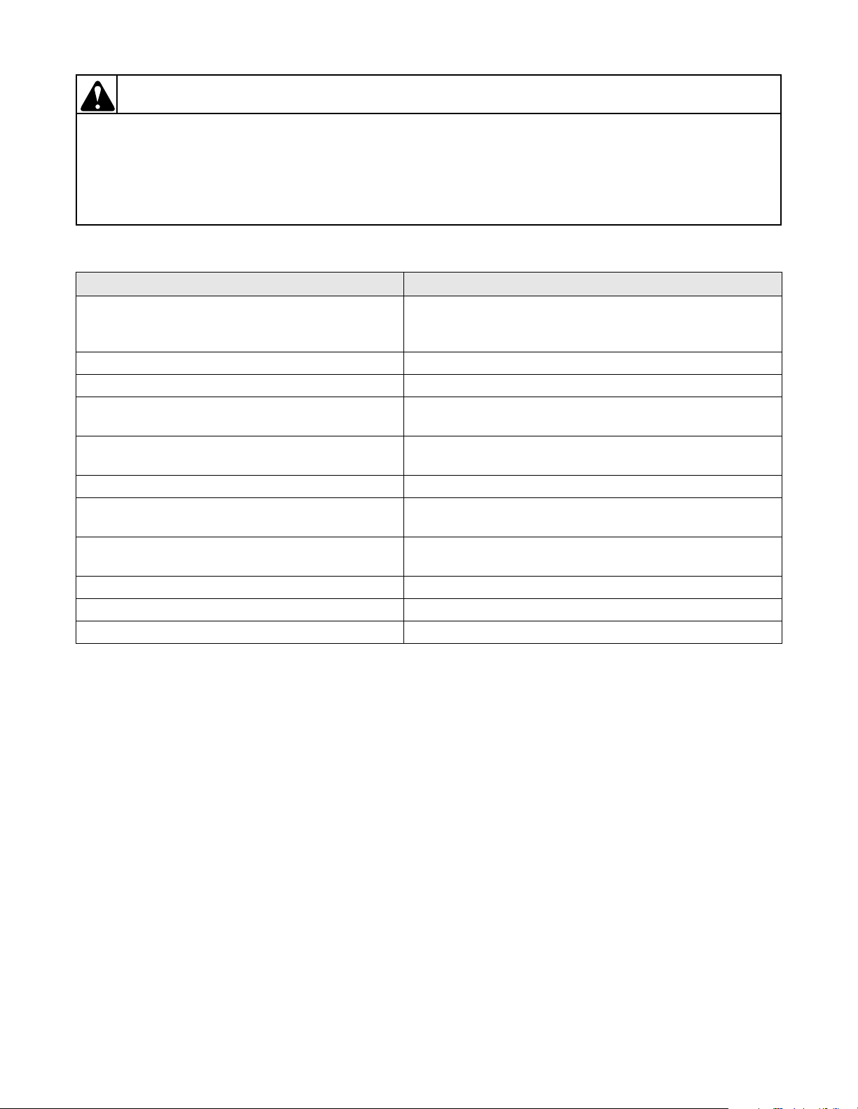
5. TIMER DOES NOT ADVANCE
POSSIBLE CAUSE TO CORRECT
Timer is designed to pause during fill periods. Some
Allow completion of fill period.
cycles have pauses (delicate cycles).
Inoperative timer. Test for continuity through timer circuits. Refer to wiring
diagram. Replace if inoperative.
Loading door is open. Close loading door. Loading door MUST be closed any time
the washer is set to agitate or spin.
Washer will not fill. Timer pauses until pressure switch is satisfied. Refer to
Paragraphs 1 and 2.
Timer motor lead wire is off timer terminal. Refer to wiring diagram and reattach wire.
Broken, loose or incorrect wiring. Refer to wiring diagram.
Make sure washer is not siphoning during rinse fill. Install siphon break kit, Part No. 562P3.
Timer is designed to pause when going from agitate
to spin.
Timer is designed to stop if washer drive motor has
been overloaded and motor thermal overload has
tripped.
Allow time for timer to go through that step. Refer to
diagram for information on time required.
Motor thermal protector reset time may vary depending
upon the reason for the washer overload, however, it should
reset within 15 minutes. Check to ensure that washer was
not overloaded with clothes.
Is circuit breaker to washer tripped, disconnecting
Reset circuit breaker.
power to washer.
Washer will not fill. Timer is designed to pause when going from spin into rinse
to allow the washtub to stop spinning before filling, make
sure that timer has advanced into fill portion of rinse cycle.
W003
39311 13
© Copyright, Alliance Laundry Systems LLC – DO NOT COPY or TRANSMIT
Section 3 Troubleshooting
WARNING
To reduce the risk of electric shock, fire, explosion, serious injury or death:
• Disconnect electric power to the washer before servicing.
• Never start the washer with any guards/panels removed.
• Whenever ground wires are removed during servicing, these ground wires must be
reconnected to ensure that the washer is properly grounded.
6. MOTOR DOES NOT RUN
POSSIBLE CAUSE TO CORRECT
Electrical power off, fuse blown or power cord not
plugged in.
Check laundry room for blown or loose fuse(s) or open
circuit breakers. (Washer itself does not have an electrical
fuse).
Loading door not closed or inoperative switch. Close door or test switch and replace if inoperative.
Timer improperly set. Reset timer, or try another cycle.
Inoperative timer. Test for continuity through timer circuits. Refer to wiring
diagram. Replace if inoperative.
Motor starting functions inoperative. No start; or
motor only hums.
Refer to Paragraph 49 to check start switch and start
windings.
Motor is dead, or will not run. Refer to Paragraph 49 to check switch and windings.
Motor overload protector has cycled. Wait two or three minutes for overload protector to reset. If
protector cycles repeatedly. Refer to Paragraph 9.
Bind in upper or lower motor bearing. Remove belt and determine if motor shaft will spin. Replace
motor if shaft is locked up.
Bind in pump (direct drive pump models). Replace pump.
Broken, loose or incorrect wiring. Refer to wiring diagram.
Power cord is wired incorrectly. Refer to wiring diagram for correct wiring.
W003
14 39311
© Copyright, Alliance Laundry Systems LLC – DO NOT COPY or TRANSMIT
Section 3 Troubleshooting
WARNING
To reduce the risk of electric shock, fire, explosion, serious injury or death:
• Disconnect electric power to the washer before servicing.
• Never start the washer with any guards/panels removed.
• Whenever ground wires are removed during servicing, these ground wires must be
reconnected to ensure that the washer is properly grounded.
7. NO AGITATION
POSSIBLE CAUSE TO CORRECT
Timer is designed to pause (SOAK) during
DELICATE cycle. Allow completion of SOAK
Test for continuity through timer circuits. Refer to wiring
diagram. Replace if inoperative.
period.
Motor will not run. Refer to Paragraph 49 to check switch and windings.
No Delicate cycle agitate. Refer to Paragraph 49 to check low speed switch and
windings.
Inoperative pressure switch. Test switch. Must have continuity from terminal 1 to 3.
Replace if inoperative.
Broken, loose or incorrect wiring. Refer to wiring diagram.
Loose or broken drive belt. Replace belt.
Inoperative transmission assembly. Repair or replace transmission assembly.
Sheared motor pulley roll pin. (Through Serial No.
001113645)
Remove drive motor and replace roll pin and any other
damaged parts.
Motor overload protector has cycled. Wait two or three minutes for overload protector to reset. If
protector cycles repeatedly. Refer to Paragraph 9.
Bind in pump. Replace pump.
Loading door is open or door switch is inoperative. Close door or test switch and replace if inoperative.
W003
8. CONSTANT AGITATION
POSSIBLE CAUSE TO CORRECT
Inoperative timer. Test for continuity through timer circuits. Refer to wiring
diagram. Replace if inoperative.
Shorted or incorrect wiring. Refer to wiring diagram.
Inoperative transmission assembly Repair or replace transmission assembly.
39311 15
© Copyright, Alliance Laundry Systems LLC – DO NOT COPY or TRANSMIT
Section 3 Troubleshooting
WARNING
To reduce the risk of electric shock, fire, explosion, serious injury or death:
• Disconnect electric power to the washer before servicing.
• Never start the washer with any guards/panels removed.
• Whenever ground wires are removed during servicing, these ground wires must be
reconnected to ensure that the washer is properly grounded.
9. WASHER OVERHEATS, CYCLES ON MOTOR THERMAL PROTECTOR, SWITCH ACTUATOR KICKS IN AND OUT
POSSIBLE CAUSE TO CORRECT
Belt is tacky and does not allow proper slip. Check belt and replace if defective.
Belt tension is too great and does not allow proper
Make sure idler spring is properly connected.
slip.
Inoperative timer. Test for continuity through timer circuits. Refer to wiring
diagram. Replace if inoperative.
Motor switch functions inoperative. Refer to Paragraph 49 to check switch functions.
Bind in water pump. Replace pump.
Brake pads or brake assembly binding. Free binding pads, or replace pads and brake assembly.
Bearings, transmission or motor has locked up and
will not turn.
Check that all these components are able to move freely.
Correct binding component.
Incorrect voltage. Contact local utility company, or have a qualified electrician
check power supply.
W003
10. SLOW SPIN OR NO SPIN
POSSIBLE CAUSE TO CORRECT
Inoperative timer. Test for continuity through timer circuits. Refer to wiring
diagram. Replace if inoperative.
Loading door is open or door safety switch is
Close loading door, or test switch and replace if inoperative.
inoperative.
Bind in water pump. Replace pump.
Loose or broken drive belt. Replace belt.
Motor will not run. Refer to Paragraph 49 to check switch and windings.
Sheared motor pulley roll pin. (Through Serial No.
001113645)
Remove drive motor and appropriately replace roll pin and
any other damaged parts.
Motor overload protector has cycled. Wait two or three minutes for overload protector to reset. If
protector cycles repeatedly, refer to Paragraph 9.
No clearance between brake pads and discs. Replace pads and brake assembly.
Broken, loose or incorrect wiring. Refer to wiring diagram.
Inoperative transmission assembly. Repair or replace the transmission assembly.
Oil on belt. Replace belt.
16 39311
© Copyright, Alliance Laundry Systems LLC – DO NOT COPY or TRANSMIT
Section 3 Troubleshooting
WARNING
To reduce the risk of electric shock, fire, explosion, serious injury or death:
• Disconnect electric power to the washer before servicing.
• Never start the washer with any guards/panels removed.
• Whenever ground wires are removed during servicing, these ground wires must be
reconnected to ensure that the washer is properly grounded.
11. CONSTANT SPIN
POSSIBLE CAUSE TO CORRECT
Inoperative timer. Test for continuity through timer circuits. Refer to wiring
diagram. Replace if inoperative.
Washtub does not stop spinning within seven
seconds after loading door is opened.
Excessive wear on brake pads, or missing brake
pads.
Shorted or incorrect wiring. Refer to wiring diagram.
Inoperative lid switch. Replace lid switch.
Replace brake pads and brake assembly.
Replace brake pads and brake assembly.
W003
12. WASHER STOPS IN CYCLE; QUITS AFTER A COUPLE LOADS; IS INTERMITTENT
POSSIBLE CAUSE TO CORRECT
Belt is tacky and does not allow proper slip. Check belt and replace if defective.
Belt tension is too great and does not allow proper
Make sure idler spring is properly connected.
slip.
Inoperative timer. Test for continuity through timer circuits. Refer to wiring
diagram. Replace if inoperative.
Broken, loose or incorrect wiring. Refer to wiring diagram.
Motor overload protector has cycled. Wait two or three minutes for overload protector to reset. If
protector cycles repeatedly. Refer to Paragraph 9.
Motor switch functions inoperative. Refer to Paragraph 49 to check switch functions.
Brake, transmission or motor has locked up and will
Check that all these components are able to move freely.
not turn.
13. WASHER IS LOCKED UP OR BINDING
POSSIBLE CAUSE TO CORRECT
Excessive belt tension. Replace belt and/or idler spring.
Bind in upper or lower bearing. Replace bearing.
Bind in water pump. Replace pump.
Bind in transmission. Repair or replace transmission.
Brake pads binding. Free binding pads, or replace pads.
Incorrect voltage. Contact local utility company, or have a qualified electrician
check power supply.
39311 17
© Copyright, Alliance Laundry Systems LLC – DO NOT COPY or TRANSMIT
Section 3 Troubleshooting
WARNING
To reduce the risk of electric shock, fire, explosion, serious injury or death:
• Disconnect electric power to the washer before servicing.
• Never start the washer with any guards/panels removed.
• Whenever ground wires are removed during servicing, these ground wires must be
reconnected to ensure that the washer is properly grounded.
14. OUTER TUB DOES NOT EMPTY
POSSIBLE CAUSE TO CORRECT
Kinked drain hose. Straighten hose.
Drain hose out of hose retainer clip in back of
cabinet.
Inoperative water pump. Replace pump.
Obstruction in outer tub outlet hose. Remove obstruction.
15. EXCESSIVE VIBRATION
POSSIBLE CAUSE TO CORRECT
Washer is not properly leveled. Adjust leveling legs.
Unbalanced load in tub. Stop washer, redistribute load, then restart washer.
Broken or disconnected centering spring(s). Connect or replace centering spring(s).
Washer is installed on weak, “spongy”, carpeted or
built-up floor.
Incorrect or loose cabinet screws. Replace with correct screws or tighten.
Base damaged (washer was dropped). Replace base assembly.
Lubricant on pivot dome and/or base friction ring. Remove lubricant or replace parts.
Partial liquid filled balance ring leaking. Replace balance ring.
Broken friction ring. Replace friction ring.
Remove washer front panel and install drain hose into hose
retainer clip in back of cabinet.
Relocate washer, or support floor to eliminate weak or
“spongy” condition.
W003
16. WATER LEAKING FROM OUTER TUB
POSSIBLE CAUSE TO CORRECT
Leaking water seal in outer tub. Replace hub and seal kit assembly. Refer to Paragraph 39.
Hole in outer tub. Replace outer tub.
Pressure hose or accumulator leaking. Replace pressure hose and/or accumulator.
Tub cover gasket leaking. Replace gasket.
Obstruction in drain causing water to come over top
Remove obstruction.
of outer drain tub cover.
Tub-to-pump hose leaking at clamp. Tighten clamp.
18 39311
© Copyright, Alliance Laundry Systems LLC – DO NOT COPY or TRANSMIT
Section 4
Grounding
WARNING
To reduce the risk of electric shock, fire, explosion, serious injury or death:
• Disconnect electric power to the washer before servicing.
• Never start the washer with any guards/panels removed.
• Whenever ground wires are removed during servicing, these ground wires must be
reconnected to ensure that the washer is properly grounded.
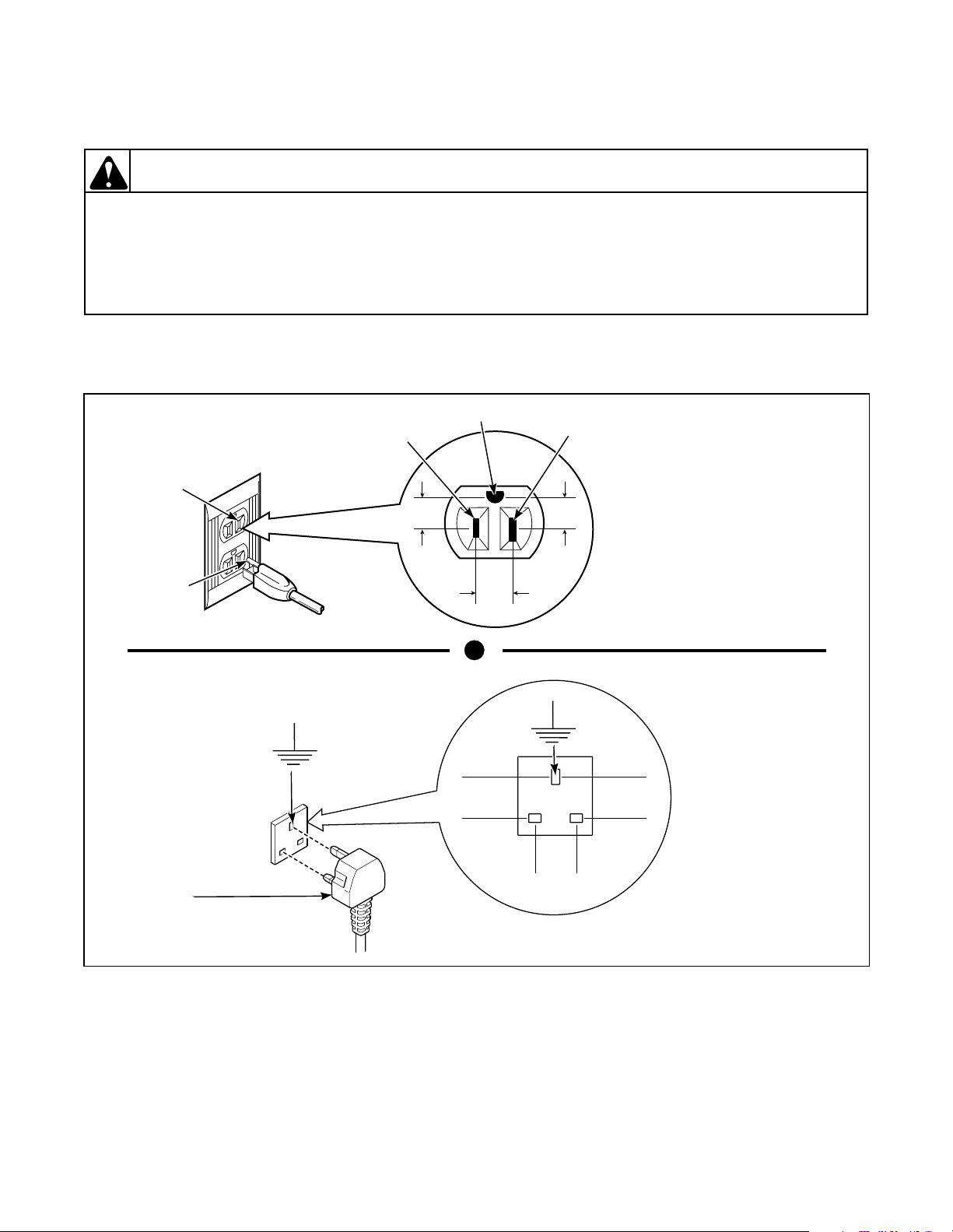
17. WALL RECEPTACLE POLARITY CHECK (Refer to Figure 1)
GROUND
NEUTRAL
0
V.A.C.
W011GE3A
NOTE: Have a qualified
electrician check polarity of
wall receptacle. If a voltage
reading is measured other
than that illustrated, the
qualified electrician should
correct the problem.
NEUTRAL
SIDE
ROUND
GROUNDING
PRONG
L1
115±12
V.A.C.
115±12
V.A.C.
W003
POWER CORD
(Fused with
13 AMP Fuse)
230 VOLTS
50 HZ
Figure 1
230 VOLTS
50 HZ
0 VOLTS
W355SE3A
NOTE: Have a
qualified electrician
check polarity of wall
receptacle. If a voltage
reading is measured
other than that
illustrated, the
qualified electrician
should correct the
problem.
39311 19
© Copyright, Alliance Laundry Systems LLC – DO NOT COPY or TRANSMIT
Section 4 Grounding
WARNING
To reduce the risk of electric shock, fire, explosion, serious injury or death:
• Disconnect electric power to the washer before servicing.
• Never start the washer with any guards/panels removed.
• Whenever ground wires are removed during servicing, these ground wires must be
reconnected to ensure that the washer is properly grounded.
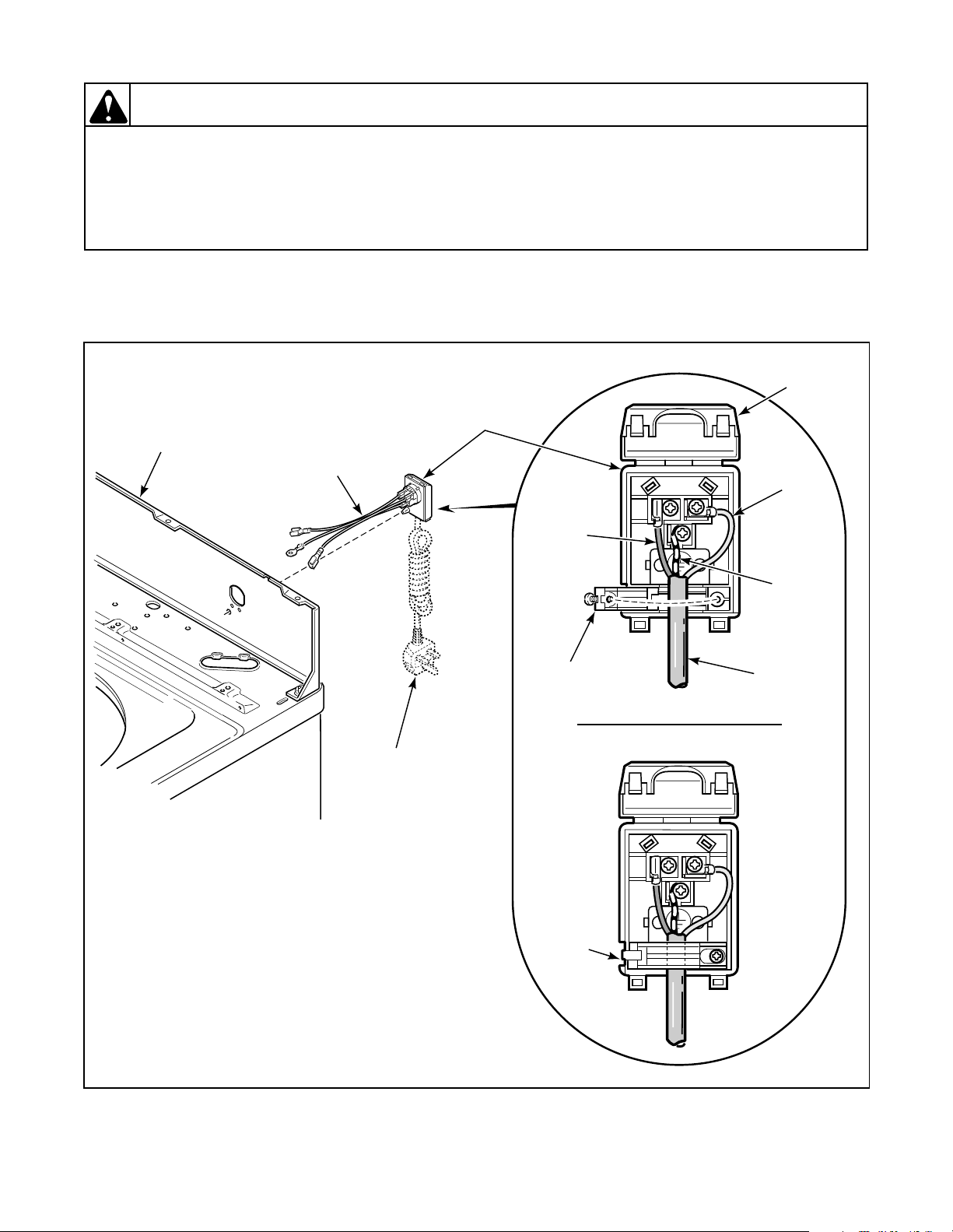
18. POWER CORD TO CONNECTION BLOCK, CONNECTION BLOCK TO CONTROL HOOD REAR
PANEL; MODELS WITH SUFFIXES B3069, 3050 AND 3062
(Refer to Figure 2)
CONNECTION
BLOCK COVER
CONNECTION
CONTROL HOOD
REAR PANEL
WIRE
HARNESS
BLOCK
BLUE
WIRE
W003
POWER
CORD
BROWN
WIRE
STRAIN RELIEF
(Open position)
STRAIN
RELIEF
(Closed
position)
L1
L1
N
N
(L2)
(L2)
GREEN/
YELLOW
WIRE
POWER
CORD
W411PE3B
Figure 2
20 39311
© Copyright, Alliance Laundry Systems LLC – DO NOT COPY or TRANSMIT
Section 4 Grounding
WARNING
To reduce the risk of electric shock, fire, explosion, serious injury or death:
• Disconnect electric power to the washer before servicing.
• Never start the washer with any guards/panels removed.
• Whenever ground wires are removed during servicing, these ground wires must be
reconnected to ensure that the washer is properly grounded.
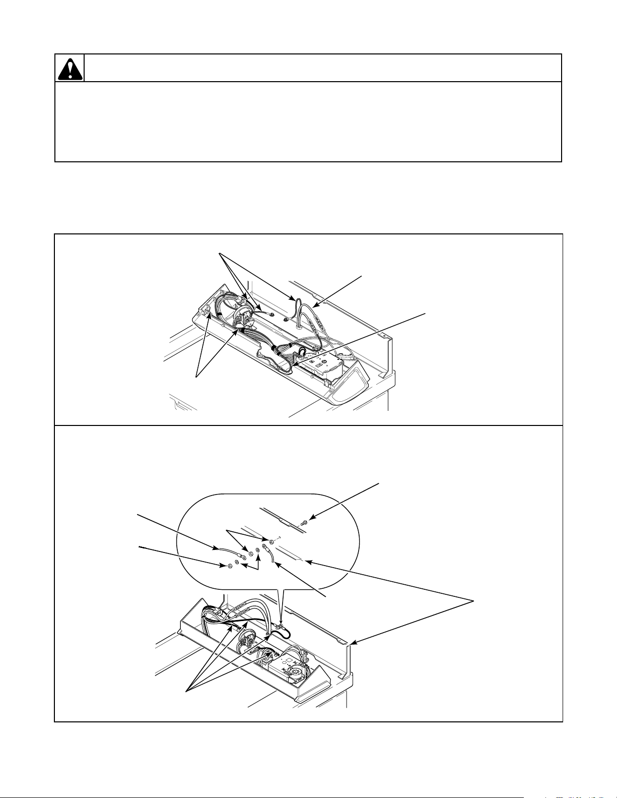
19. POWER CORD TO CABINET TOP, CABINET TOP TO CONTROL HOOD MOUNTING
BRACKET, PRESSURE SWITCH MOUNTING BRACKET AND GROUND TAB ON GRAPHIC
PANEL
(See Figure 3)
GROUND
WIRES
POWER
CORD
GROUND
WIRES
W003
GROUND
WIRES
W505SE3B
POWER CORD TO CONTROL HOOD REAR PANEL, CONTROL HOOD REAR PANEL TO
CONTROL HOOD MOUNTING BRACKET, PRESSURE SWITCH MOUNTING BRACKET AND
GROUND TAB ON GRAPHIC PANEL
SCREW
HOOD HARNESS
EARTH (Ground)
WIRE
NUT
NUT
WASHER
CONTROL
POWER CORD EARTH
(Ground) WIRE
HOOD REAR
PANEL
EARTH
(Ground)
WIRES
W356SE3B
Figure 3
39311 21
© Copyright, Alliance Laundry Systems LLC – DO NOT COPY or TRANSMIT
Section 4 Grounding
WARNING
To reduce the risk of electric shock, fire, explosion, serious injury or death:
• Disconnect electric power to the washer before servicing.
• Never start the washer with any guards/panels removed.
• Whenever ground wires are removed during servicing, these ground wires must be
reconnected to ensure that the washer is properly grounded.
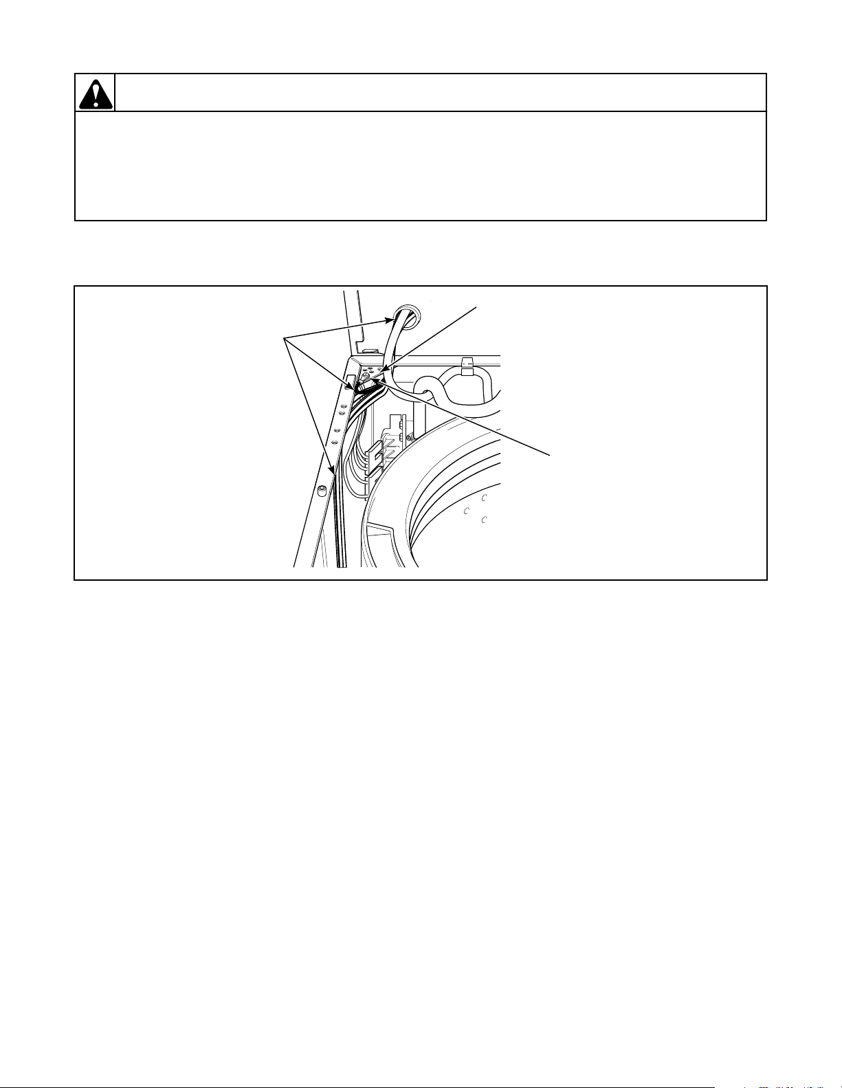
20. CONTROL HOOD WIRE HARNESS TO TOP LEFT REAR CORNER GUSSET OF CABINET (Refer to Figure 4)
CORNER
GUSSET
GROUND
WIRES
GROUND
SCREW
W003
Figure 4
W426SE2A
22 39311
© Copyright, Alliance Laundry Systems LLC – DO NOT COPY or TRANSMIT
Section 4 Grounding
WARNING
To reduce the risk of electric shock, fire, explosion, serious injury or death:
• Disconnect electric power to the washer before servicing.
• Never start the washer with any guards/panels removed.
• Whenever ground wires are removed during servicing, these ground wires must be
reconnected to ensure that the washer is properly grounded.
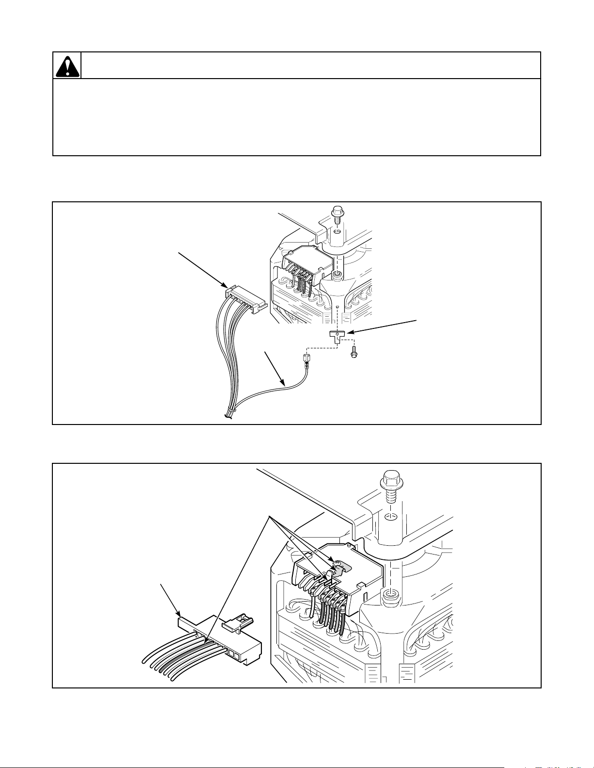
21. WIRE HARNESS TO MOTOR (Refer to Figures 5 and 6)
WIRE HARNESS
CONNECTION
BLOCK
GROUNDING
TERMINAL
GROUND
WIRE
W003
WIRE
HARNESS
CONNECTION
BLOCK
TLW1227G
Figure 5
Models with suffixes ending 3050
GROUND
WIRES
W329SE3B
Figure 6
All other Models
39311 23
© Copyright, Alliance Laundry Systems LLC – DO NOT COPY or TRANSMIT

Section 4 Grounding
Notes
24 39311
© Copyright, Alliance Laundry Systems LLC – DO NOT COPY or TRANSMIT
Section 5
Service Procedures
WARNING
To reduce the risk of electric shock, fire, explosion, serious injury or death:
• Disconnect electric power to the washer before servicing.
• Never start the washer with any guards/panels removed.
• Whenever ground wires are removed during servicing, these ground wires must be
reconnected to ensure that the washer is properly grounded.
W003
IMPORTANT: When reference is made to
directions (right or left) in this manual, it is from
operator’s position facing front of washer.
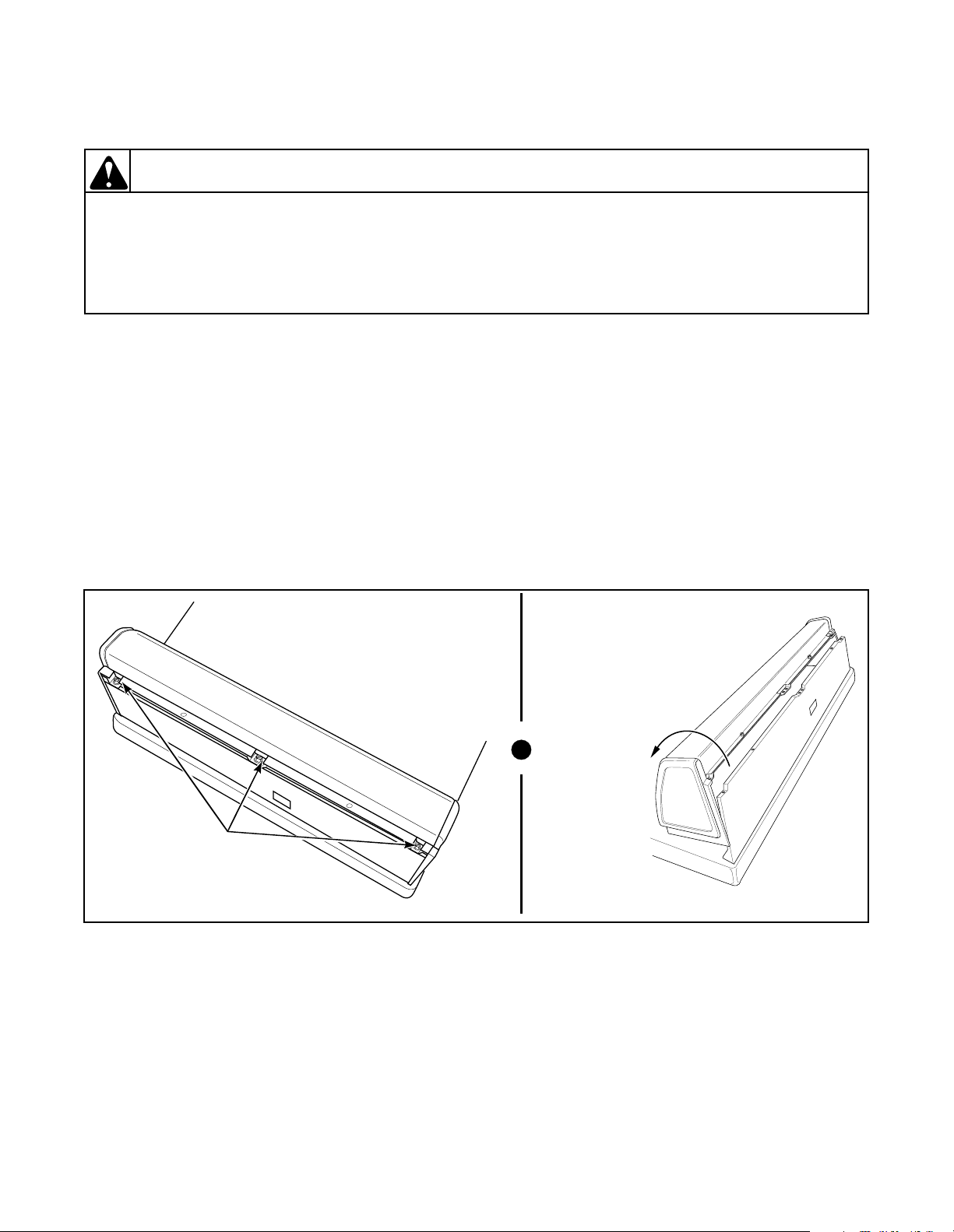
22. CONTROL HOOD ASSEMBLY
a. Remove three screws holding rear of hood
assembly to control hood rear panel.
Refer to Figure 7.
b. Pivot hood assembly forward on cabinet top.
Refer to Figure 7.
c. Carefully remove bottom front of hood from
clips on cabinet top.
d. Disconnect wires from component parts and
carefully remove components from hood
assembly.
NOTE: Refer to wiring diagram when rewiring
component parts.
TO REMOVE CONTROL HOOD END
PANELS
Remove four screws holding end panels to control
mounting plate. Refer to Figures 8, 9, 10 or 11.
PIVOT
HOOD
FORWARD
HOOD
ATTACHING
SCREWS
W169SE3B
Figure 7
39311 25
© Copyright, Alliance Laundry Systems LLC – DO NOT COPY or TRANSMIT
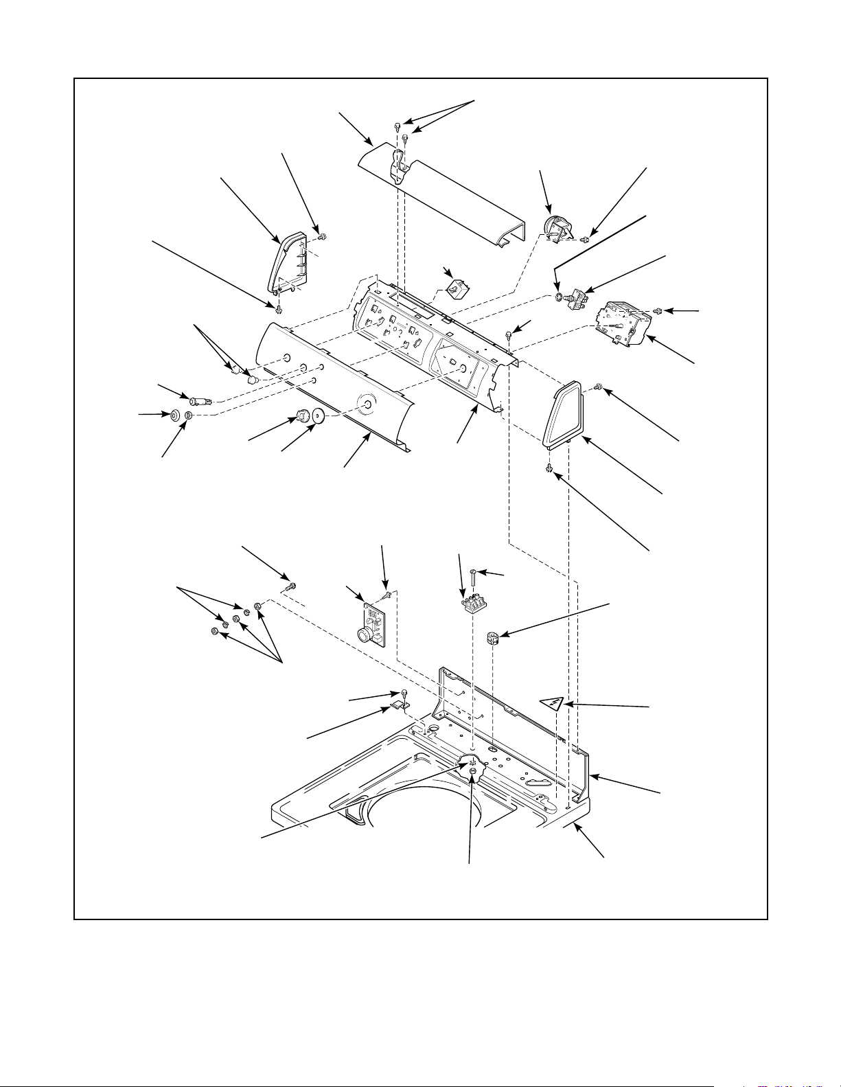
W252IE1A
Section 5 Service Procedures
SCREW
INDICATOR
LIGHT
SWITCH
COLLAR
KNURLED
LOCKWASHERS
CONTROL
NUT
END CAP
KNOBS
(Left)
TIMER
KNOB
SCREW
SCREW
TIMER
KNOB
SKIRT
TOP
COVER
GRAPHIC
PANEL
SUPPORT
LID LOCK
CONTROL
SCREWS
TEMPERATURE
SWITCH
CONTROL
MOUNTING
PLATE
TERMINAL
BLOCK
PRESSURE
SWITCH
SCREW
SCREW
SCREW
LOCKWASHER
SWITCH
ASSEMBLY
SCREW
TIMER
SCREW
END CAP
(Right)
SCREW
STRAIN
RELIEF
NUT
HOLD-DOWN
LOCKWASHER
CLIP
SCREW
NUT
CABINET TOP
STICKER
CONTROL
HOOD REAR
PANEL
W371PE3C
Figure 8
GRAPHIC PANEL, CONTROL MOUNTING PLATE AND CONTROLS
(Models LWS17A
*B3069, LWZ17A*B3069, LWS17M*B3069 and LWZ17M*B3069
through Serial No. 00061999)
26 39311
© Copyright, Alliance Laundry Systems LLC – DO NOT COPY or TRANSMIT
 Loading...