

Page 1
Drying Tumblers
TMB1268C
120 Pound Capacity
170 Pound Capacity
Models Starting Serial No. 0907003062
Refer to Page 7 for Model Numbers
Troubleshooting
www.comlaundry.com
Part No. 70422201
December 2009
Page 2

Page 3

Table of
Content s
Section 1 – Safety Information ...............................................................3
Locating an Authorized Service Person................................................5
Safety Warnings and Decals..................................................................5
Safety Precautions for Servicing Tumblers...........................................5
Section 2 – Introduction..........................................................................6
Model Identification..............................................................................6
Customer Service...................................................................................8
Serial Plate Location..............................................................................8
How a Tumbler Works..........................................................................9
Section 3 – Troubleshooting..................................................................10
1. Motor Does Not Start..................................................................11
2. Motor Overload Protector Cycles Repeatedly............................12
3. Motor Runs But Cylinder Does Not Turn...................................13
4. Motor Does Not Stop..................................................................14
5. Gas Burner Does Not Ignite........................................................15
6. Burner Ignites and Goes Out Repeatedly....................................16
7. Burner Shuts off Prematurely .....................................................17
8. Burner Repeatedly Cycles Off On High Limit Thermostat........18
9. Steam Valve or Burner Does Not Shut-off.................................19
10. Clothes Do Not Dry ....................................................................20
11. Tumbler Overheating..................................................................21
12. Burners Not Burning Properly - Gas Models..............................22
13. Loading Door Opens During Operation......................................23
14. Tumbler Runs But No Steam To Coils - Steam Models.............24
15. Water In Steam Line - Steam Models.........................................25
16. Tumbler Will Not Start, Time On Drying Timer,
Door Closed ................................................................................26
17. Motor Runs But Will Not Heat...................................................29
18. Cylinder Turns, But Will Not Heat.............................................30
Section 4 – Adjustments........................................................................32
19. Main Gas Burner Air Inlet Shutters (All Gas Models)...............32
20. Airflow Switch............................................................................33
21. Loading Door Strike....................................................................33
22. Cylinder Belt Tension.................................................................33
23. Cylinder Clearance......................................................................34
24. Drive Belt Tension......................................................................37
25. Fan Belt Tension.........................................................................37
Section 5 – Hybrid Timer Control Troubleshooting..........................39
26. Control Has No Display..............................................................40
27. Display Flashes “dr” With Door Closed.....................................42
28. Motor Will Not Start/Run...........................................................44
29. Unit Will Not Heat – Gas............................................................46
30. Error Codes.................................................................................49
© Copyright 2009, Alliance Laundry Systems LLC.
All rights reserved. No part of the contents of this book may be reproduced or transmitted in any form or by any means without
the expressed written consent of the publisher.
70422201 1
© Copyright, Alliance Laundry Systems LLC – DO NOT COPY or TRANSMIT
Page 4

Section 6 – On Premise Micro Control (RM) Troubleshooting ........50
31. Control Has No Display..............................................................51
32. Door Open Indicator ...................................................................53
33. Motor Will Not Start/Run...........................................................56
34. Unit Will Not Heat – Gas/Steam ................................................58
35. Error Codes.................................................................................61
2 70422201
© Copyright, Alliance Laundry Systems LLC – DO NOT COPY or TRANSMIT
Page 5
Section 1
Danger indicates an imminently hazardous
situation that, if not avoided, will cause
severe personal injury or death.
DANGER
Warning indicates a hazardous situation
that, if not avoided, could cause severe
personal injury or death.
WARNING
Caution indicates a hazardous situation
that, if not avoided, may cause minor or
moderate personal injury or property
damage.
CAUTION
• Failure to install, maintain and/or operate this
product according to the manufacturer’s
instructions may result in conditions which
can produce serious injury, death and/or
property damage.
• Do not repair or replace any part of the
product or attempt any servicing unless
specifically recommended or published in this
Service Manual and unless you understand
and have the skills to carry out the servicing.
• Whenever ground wires are removed during
servicing, these ground wires must be
reconnected to ensure that the product is
properly grounded and to reduce the risk of
fire, electric shock, serious injury or death.
W006R2
•
WARNING
Safety Information
Throughout this manual and on machine decals, you
will find precautionary statements (“CAUTION”,
“WARNING”, and “DANGER”) followed by specific
instructions. These precautions are intended for the
personal safety of the operator, user, servicer, and those
maintaining the machine.
In the interest of safety, some general precautions
relating to the operation of this machine follow.
Additional precautionary statements (“IMPORTANT”
and “NOTE”) are followed by specific instructions.
IMPORTANT: The word “IMPORTANT” is used
to inform the reader of specific procedures where
minor machine damage will occur if the procedure
is not followed.
NOTE: The word “NOTE” is used to communicate
installation, operation, maintenance or servicing
information that is important but not hazard
related.
70422201 3
© Copyright, Alliance Laundry Systems LLC – DO NOT COPY or TRANSMIT
Page 6
Safety Information
To reduce the risk of electric shock, fire,
explosion, serious injury or death:
• Disconnect electric power to the tumbler
before servicing.
• Never start the tumbler with any guards/
panels removed.
• Whenever ground wires are removed during
servicing, these ground wires must be
reconnected to ensure that the tumbler is
properly grounded.
W240
WARNING
Repairs that are made to your products by
unqualified persons can result in hazards due to
improper assembly or adjustments subjecting
you, or the inexperienced person making such
repairs, to the risk of serious injury, electrical
shock, or death.
W007
WARNING
If you or an unqualified person perform service
on your product, you must assume the
responsibility for any personal injury or
property damage which may result. The
manufacturer will not be responsible for any
injury or property damage arising from
improper service and/or service procedures.
W008
CAUTION
IMPORTANT INFORMATION: During the
lifetime of a tumbler, it may require service. The
information contained in this manual was written
and is intended for use by qualified service
technicians who are familiar with the safety
procedures required in the repair of a tumbler, and
who are equipped with the proper tools and testing
equipment.
NOTE: The WARNING and IMPORTANT
instructions appearing in this manual are not meant
to cover all possible conditions and situations that
may occur. It must be understood that common
sense, caution and carefulness are factors which
CANNOT be built into this tumbler. These factors
MUST BE supplied by the person(s) installing,
maintaining or operating the tumbler.
Always contact your dealer, distributor, service agent
or the manufacturer on any problems or conditions you
do not understand.
4 70422201
© Copyright, Alliance Laundry Systems LLC – DO NOT COPY or TRANSMIT
Page 7

Safety Information
Locating an Authorized Service
Person
Alliance Laundry Systems is not responsible for
personal injury or property damage resulting from
improper service. Review all service information
before beginning repairs.
Warranty service must be performed by an
authorized technician, using authorized factory
parts. If service is required after the warranty
expires, Alliance Laundry Systems also
recommends contacting an authorized technician
and using authorized factory parts.
Safety Warnings and Decals
SAFETY WARNINGS and decals have been provided
in key locations to remind you of important precautions
for the safe operation and maintenance of your tumbler.
Please take the time to review these warnings before
proceeding with service work.
All decals have been designed and applied to withstand
washing and cleaning. Decals should be checked
periodically to be sure they have not been damaged,
removed, or painted. Refer to the Parts Manual for
ordering replacement decals.
Safety Precautions for Servicing
Tumblers
• Disconnect electrical service.
• Shut off supply gas valve before servicing gas
components.
• Access panel MUST be reinstalled after
inspection or servicing of tumbler is
completed.
• Use a non-corrosive leak detecting compound
to check all pipe connections for gas leaks. DO
NOT USE AN OPEN FLAME TO CHECK
FOR GAS LEAKS!
• Belt guard MUST be reinstalled after
inspection or servicing of tumbler is
completed.
• Contactor box cover MUST be reinstalled
after inspection or servicing of electric and/or
reversing tumbler is completed.
• Loading door switch MUST be operational
before putting tumbler into service.
• Junction box cover MUST be reinstalled after
inspection or servicing of tumbler is
completed.
70422201 5
© Copyright, Alliance Laundry Systems LLC – DO NOT COPY or TRANSMIT
Page 8

Section 2
Introduction
Model Identification
Information in this manual is applicable to these models:
Gas Steam/Thermal Oil
HU120L
HU120N
IT120L
IT120N
KA120L
KA120N
KT120L
KT120N
KU120L
KU120N
LA120L
LA120N
LT120L
LT120N
LU120L
LU120N
PA120L
PA120N
PT120L
PT120N
PU120L
PU120N
120
Pound
BA120L
BA120N
BT120L
BT120N
BU120L
BU120N
CA120L
CA120N
CT120L
CT120N
CU120L
CU120N
GA120L
GA120N
GT120L
GT120N
GU120L
GU120N
HA120L
HA120N
HT120L
HT120N
SA120L
SA120N
ST120L
ST120N
SU120L
SU120N
UA120L
UA120N
UT120L
UT120N
UU120L
UU120N
XT120L
XT120N
XU120L
XU120N
YT120L
YT120N
BT120S
BT120T
BU120S
BU120T
CT120S
CT120T
CU120S
CU120T
GT120S
GT120T
GU120S
GU120T
HT120S
HT120T
HU120S
HU120T
IT120S
IT120T
KT120S
KT120T
KU120S
KU120T
LT120S
LT120T
LU120S
LU120T
PT120S
PT120T
PU120S
PU120T
ST120S
ST120T
SU120S
SU120T
UT120S
UT120T
UU120S
UU120T
XT120S
XT120T
XU120S
XU120T
YT120S
YT120T
YU120S
YU120T
6 70422201
© Copyright, Alliance Laundry Systems LLC – DO NOT COPY or TRANSMIT
Page 9

170
Pound
BA170L
BA170N
BT170L
BT170N
BU170L
BU170N
CA170L
CA170N
CT170L
CT170N
CU170L
CU170N
GA170L
GA170N
GT170L
GT170N
GU170L
GU170N
HA170L
HA170N
HT170L
HT170N
Gas Steam/Thermal Oil
HU170L
HU170N
IT170L
IT170N
KA170L
KA170N
KT170L
KT170N
KU170L
KU170N
LA170L
LA170N
LT170L
LT170N
LU170L
LU170N
PA170L
PA170N
PT170L
PT170N
PU170L
PU170N
SA170L
SA170N
ST170L
ST170N
SU170L
SU170N
UA170L
UA170N
UT170L
UT170N
UU170L
UU170N
XT170L
XT170N
XU170L
XU170N
YT170L
YT170N
BT170S
BT170T
BU170S
BU170T
CT170S
CT170T
CU170S
CU170T
GT170S
GT170T
GU170S
GU170T
HT170S
HT170T
HU170S
HU170T
IT170S
IT170T
KT170S
KT170T
KU170S
KU170T
Introduction
LT170S
LT170T
LU170S
LU170T
PT170S
PT170T
PU170S
PU170T
ST170S
ST170T
SU170S
SU170T
UT170S
UT170T
UU170S
UU170T
XT170S
XT170T
XU170S
XU170T
YT170S
YT170T
Includes models with the following control suffixes:
R3 – reversing DX4 OPL RQ – reversing dual digital timer
RD – reversing DMP OPL
RM – reversing OPL micro
70422201 7
© Copyright, Alliance Laundry Systems LLC – DO NOT COPY or TRANSMIT
Page 10

Introduction
TMB2288N
120 Pound
Junction
Box
Cover
Serial
Plate
Serial
Plate
Junction
Box
Cover
170 Pound
Customer Service
If literature or replacement parts are required, contact
the source from whom the machine was purchased or
contact Alliance Laundry Systems at (920) 748-3950
for the name and address of the nearest authorized
parts distributor.
For technical assistance, call (920) 748-3121.
Serial Plate Location
When calling or writing about your product, be sure to
mention model and serial numbers. Model and serial
numbers are located on serial plate as shown.
8 70422201
© Copyright, Alliance Laundry Systems LLC – DO NOT COPY or TRANSMIT
Page 11

How a Tumbler Works
1
3
Introduction
A tumbler uses heated air to dry loads of laundry.
① When the motor is started, the exhaust fan pulls
room temperature air in through the air intake at
the rear of the tumbler and over the heat source
(burner flame for gas, heating element for
2
electric, and coil for steam).
② The heated air moves into the cylinder , where it is
circulated through the wet load by the tumbling
action of the cylinder.
③ The air then passes throug h the lint filter, exhaust
fan, and is vented to the outdoors.
TMB2347S
70422201 9
© Copyright, Alliance Laundry Systems LLC – DO NOT COPY or TRANSMIT
Page 12

Section 3
To reduce the risk of electric shock, fire, explosion, serious injury or death:
• Disconnect electric power to the tumbler before servicing.
• Close gas shut-off valve to gas tumbler before servicing.
• Close steam valve to steam tumbler before servicing.
• Never start the tumbler with any guards/panels removed.
• Whenever ground wires are removed during servicing, these ground wires must be reconnected to
ensure that the tumbler is properly grounded.
W002
WARNING
Troubleshooting
IMPORTANT: Refer to appropriate wiring
diagram for aid in testing tumbler components.
10 70422201
© Copyright, Alliance Laundry Systems LLC – DO NOT COPY or TRANSMIT
Page 13
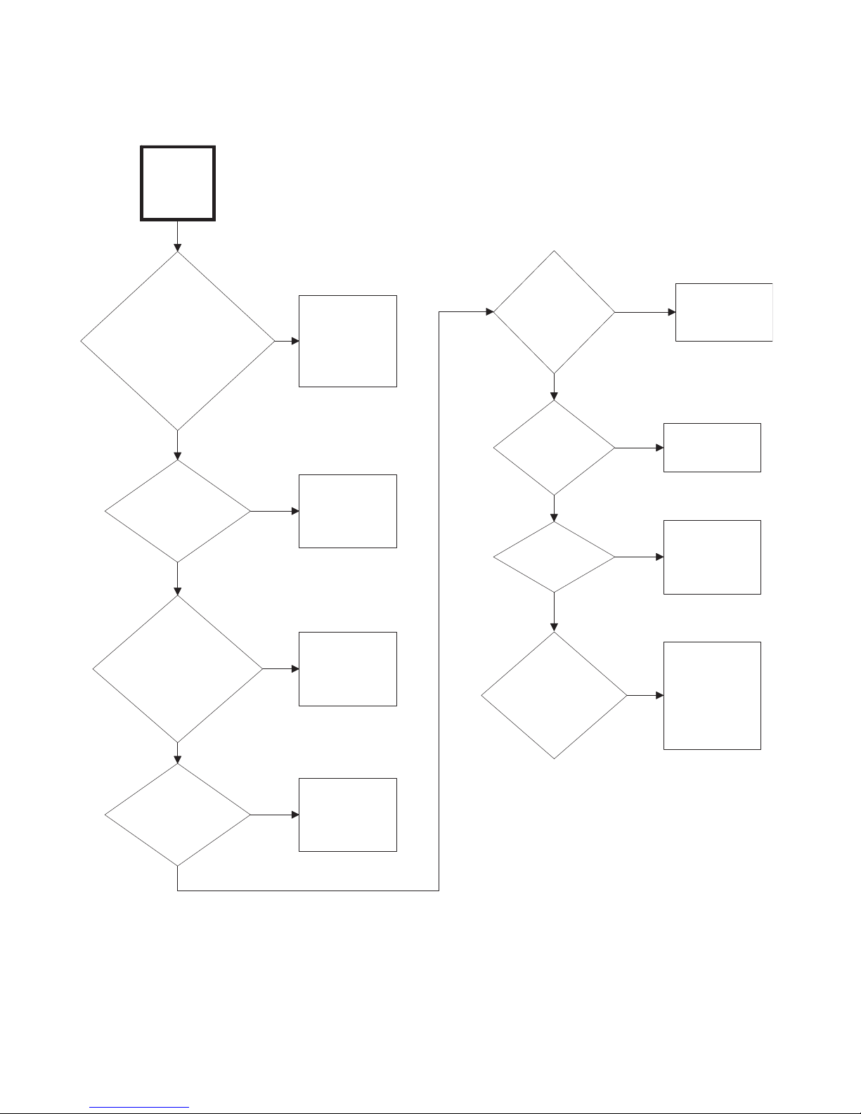
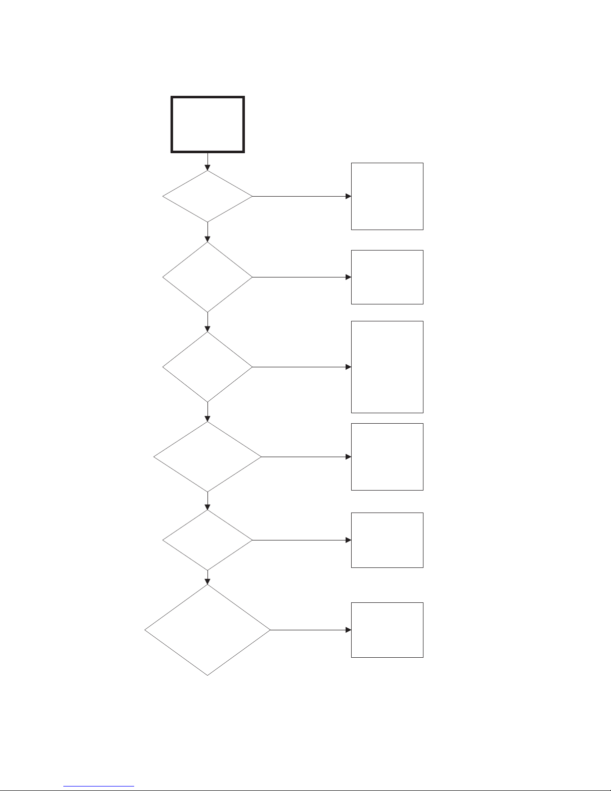
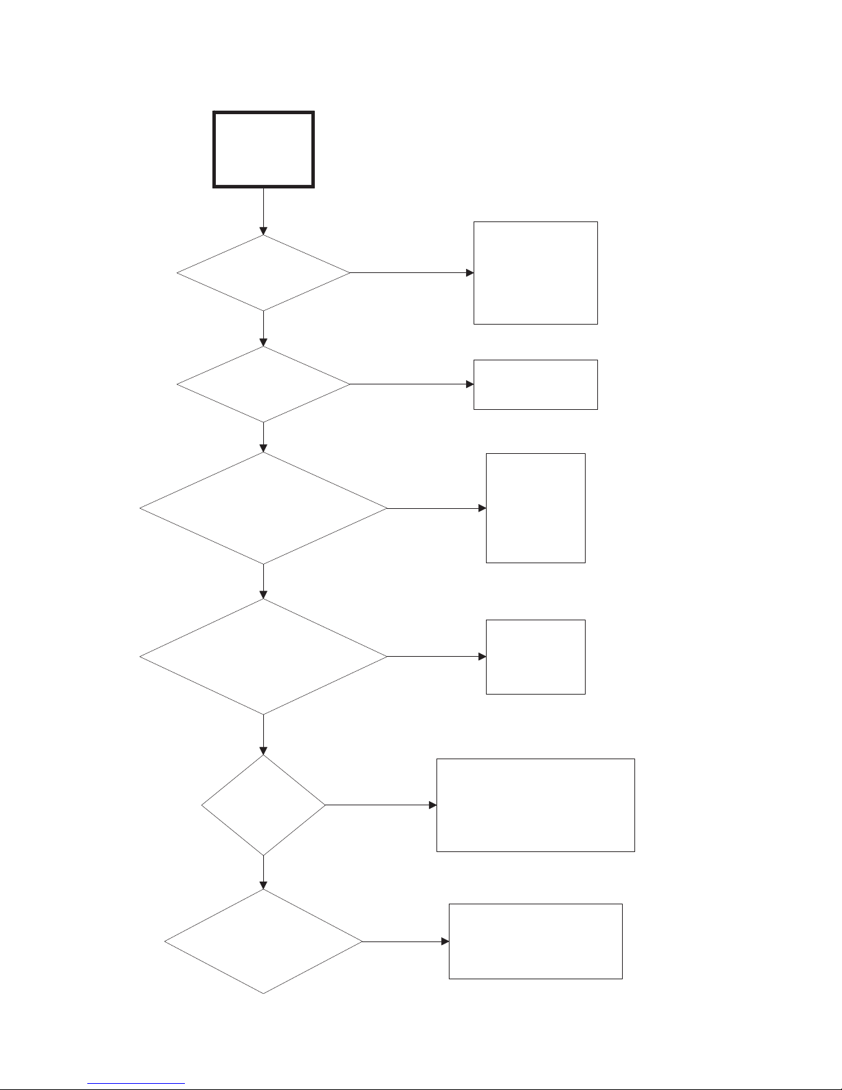
1. Motor Does Not Start
TMB2360S
Motor does
not start
Is electrical power
off, has circuit
breaker tripped or
has control fuse
blown?
Check service
to tumbler.
Check primary
and secondary
fuses.
Is transformer
inoperative?
Replace
transformer.
Is loading door
open or is door
switch
inoperative?
Close door or
test switch and
replace if
inoperative.
Is lint panel
switch not
closing?
Test lint panel
switch, replace
if inoperative.
Are trunnion
bearings
binding?
Replace
trunnion
bearings.
Is there
broken, loose
or incorrect
wiring?
Refer to wiring
diagram
located on
back of tumbler
or in literature
packet.
Ye s
No
Ye s
No
Ye s
No
Ye s
Ye s
No
Ye s
Are idler
bearings
binding?
Replace
bearings.
Is motor
inoperative?
Have motor
tested and
replace if
inoperative.
Ye s
No
No
Ye s
No
TMB2360S
Troubleshooting
70422201 11
© Copyright, Alliance Laundry Systems LLC – DO NOT COPY or TRANSMIT
Page 14
Troubleshooting
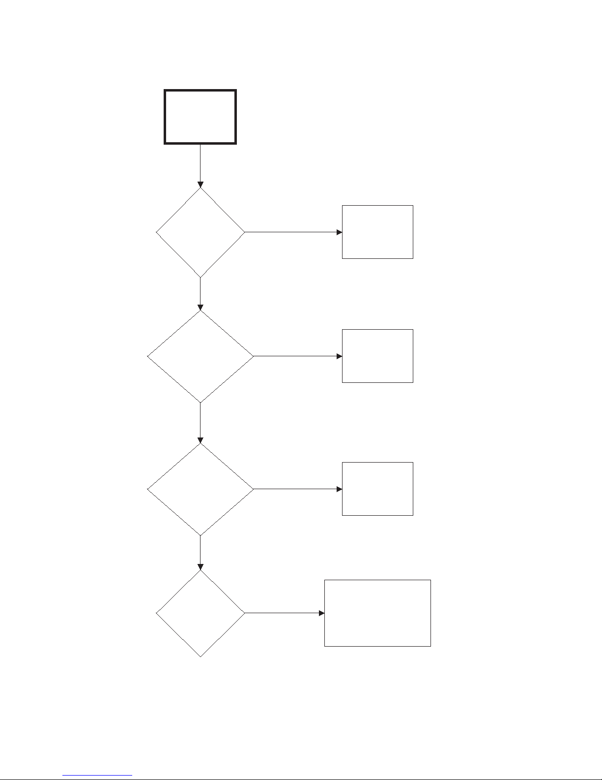
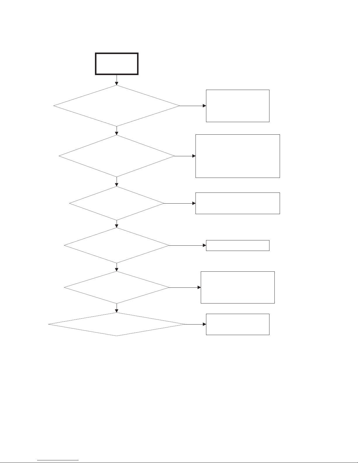
2. Motor Overload Protector Cycles Repeatedly
Motor overload
protector
cycles
repeatedly
Is voltage
incorrect?
No
Yes
Refer to the
Installation
Manual for
electrical
requirements.
Is clothes
load too
large?
No
Is clothes
cylinder
binding?
No
Is wiring
inadequate?
No
Has lint
built up?
Yes
Yes
Yes
Yes
Remove part of
load.
Check cylinder
for binding.
Refer to
Adjustments
Section for
cylinder
adjustment.
Check with an
electrician to
ensure that
wiring is
adequate.
Clean lint
accumulation
on and around
motor.
Is there broken,
loose or
incorrect wiring?
12 70422201
© Copyright, Alliance Laundry Systems LLC – DO NOT COPY or TRANSMIT
No
Yes
Refer to wiring
diagram
located inside
contactor box.
TMB2361S
Page 15
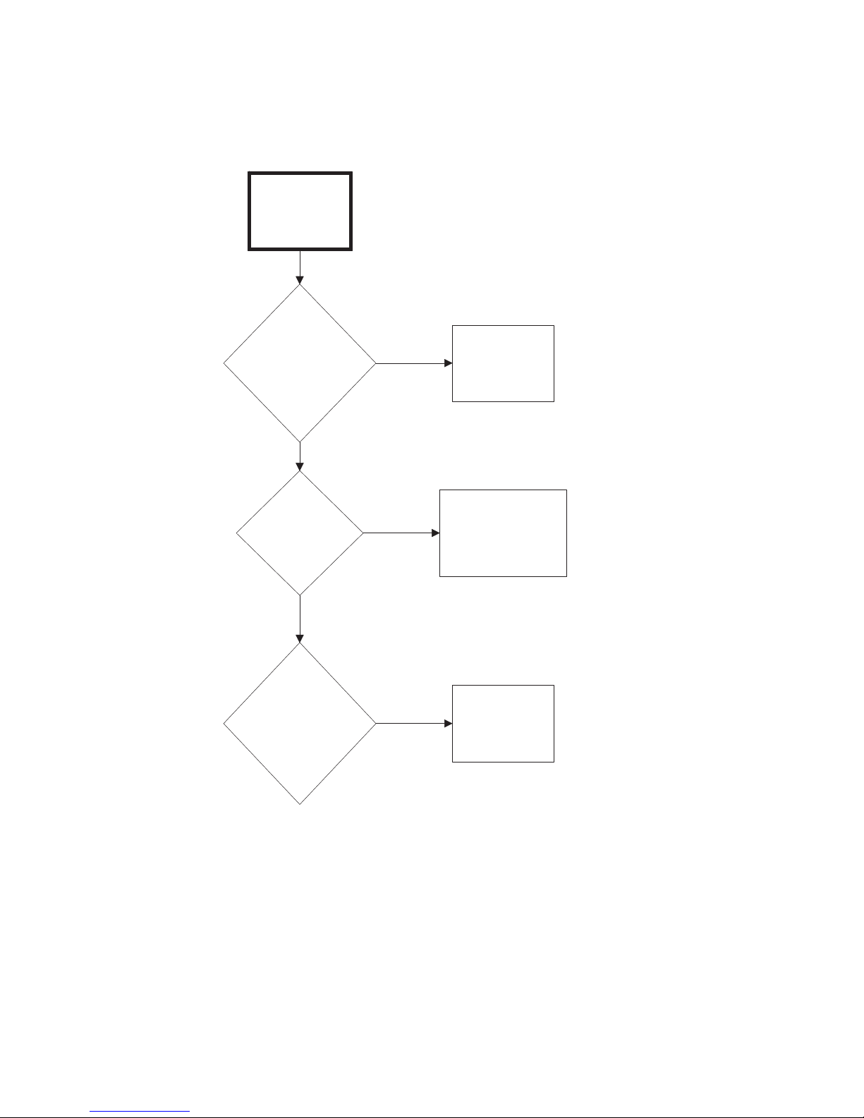
3. Motor Runs But Cylinder Does Not Turn
Motor runs but
cylinder does
not turn
Troubleshooting
Is motor
drive pulley
loose?
No
Are cylinder
belts broken
or loose?
No
Is drive belt
broken or
loose?
Ye s
Ye s
Ye s
Tighten drive
pulley bushing
screws.
Replace or
adjust belts.
Replace or
adjust belt.
Is cylinder
binding?
70422201 13
© Copyright, Alliance Laundry Systems LLC – DO NOT COPY or TRANSMIT
No
Ye s
Check cylinder for
binding. Refer to
Adjustments Section
for proper cylinder
adjustment.
TMB1919S
Page 16
Troubleshooting
Motor does not
stop
Is door switch
or lint panel
switch
inoperative?
Test switches
and replace if
inoperative.
Is motor
contactor
inoperative?
Test motor
contactor and
replace if
inoperative.
TMB2362S
Yes
No
Yes
Is wiring
incorrect?
Refer to wiring
diagram located on
back of tumbler or
in literature packet.
Yes
No
4. Motor Does Not Stop
14 70422201
© Copyright, Alliance Laundry Systems LLC – DO NOT COPY or TRANSMIT
Page 17
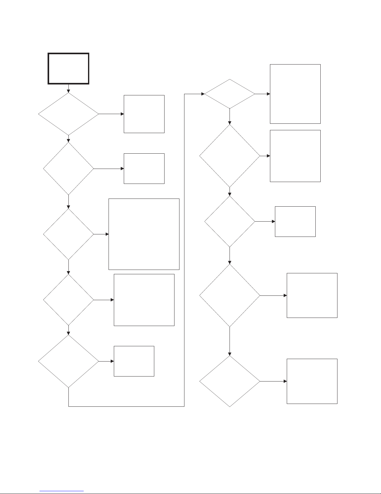
5. Gas Burner Does Not Ignite
TMB2363S
Troubleshooting
Gas burner
does not ignite
Is exhaust
system
inadequate?
No
Is
thermostat
inoperative?
No
Is gas
supply
insufficient?
No
Refer to the
Yes
Installation
Manual for
exhaust system
requirements.
Yes
Test thermostat
and replace if
inoperative.
Open partially closed gas
shut-off valve or correct low
gas pressure. Check
Yes
manifold pressure and
adjust to pressure specified
on serial plate. If pressure
cannot be obtained, have
gas supplier check main
pressure.
Is there lint
buildup?
No
Is make-up
air or
ductwork
inadequate?
No
Is airflow
switch
inoperative?
No
Clean lint
compartment after
every eight-hour
Yes
shift. Check back
draft damper for lint
accumulation.
Check ductwork for
lint build-up.
Refer to
Installation
Manual to ensure
Yes
that ductwork and
make-up air
openings are sized
properly.
Test switch and
Yes
replace if
inoperative.
Are orifices
incorrect?
No
Are gas valve
coils
inoperative?
No
Tumbler is equipped for
type of gas specified on
Yes
serial plate. If orifices
are different from that
specified on serial
plate, obtain and install
proper orifices.
Test coils and
Yes
replace if
inoperative.
Is there
broken, loose
or incorrect
wiring?
No
Is there
improper fan
rotation?
Yes
Yes
Refer to wiring
diagram located on
back of tumbler or
in literature packet.
May be due to
improper wiring
resulting in low
airflow. Refer to
Installation
Manual.
TMB2363S
70422201 15
© Copyright, Alliance Laundry Systems LLC – DO NOT COPY or TRANSMIT
Page 18
Troubleshooting
Burner ignites
and goes out
repeatedly
Is gas pressure
insufficient?
Check gas supply
and pressure. Low
flame will not
maintain sensor
conductivity.
Are burner ports
plugged?
Check burner tubes
for build-up.
Is exhaust system or
make-up air
inadequate?
Refer to
Installation
Manual for
exhaust and
make-up air
requirements.
Is high limit or cabinet
limit thermostat
inoperative?
Test thermostat
and replace if
inoperative.
TMB1922S
Are orifices
improper?
Tumbler is equipped for type of
gas specified on serial plate. If
orifices are different from that
specified on serial plate, obtain
and install proper orifices.
Is flame recognition
circuit improper?
Replace high voltage lead.
Replace igniter.
Replace ignition control
module.
Yes
No
Yes
No
Yes
No
Yes
No
Yes
No
Yes
6. Burner Ignites and Goes Out Repeatedly
16 70422201
© Copyright, Alliance Laundry Systems LLC – DO NOT COPY or TRANSMIT
Page 19
7. Burner Shuts off Prematurely
Burner shuts
off prematurely
Is there improper or
inadequate exhaust and/or
make-up air?
Refer to Installation
Manual for exhaust
and make-up air
requirements.
Is tumbler not properly
equipped for type of gas
used or altitude?
Tumbler is equipped for type of
gas specified on serial plate. If
not properly equipped for gas
type and altitude, obtain and
install correct components.
Is burner flame
improperly adjusted?
Refer to Adjustments Section
for burner flame adjustment.
Is high limit thermostat
cycling off?
Refer to Paragraph 8.
Ye s
No
Ye s
No
Ye s
No
Ye s
No
TMB2364S
Is fan rotation improper?
May be due to improper
wiring resulting in low
airflow. Refer to
Installation Manual..
Are gas valve coils inoperative?
Test coils and replace if
inoperative.
Ye s
No
Ye s
Troubleshooting
70422201 17
© Copyright, Alliance Laundry Systems LLC – DO NOT COPY or TRANSMIT
Page 20

Troubleshooting
Burner repeatedly
cycles off on high
limit thermostat
Is external exhaust
system longer than
recommended or is
there inadequate
make-up air?
Refer to
Installation
Manual for
exhaust and
make-up air
requirements.
Is lint
screen
clogged?
Remove screen
and clean. Lint
screen and
compartment
should be cleaned
after every eight
hour shift.
Is there lint
in internal
tumbler
ductwork?
Disassemble
tumbler
ductwork and
clean.
Is there lint
in external
exhaust
system?
Disassemble
exhaust system
and clean.
Is high limit
thermostat
cycling at too low
a temperature?
Replace
thermostat.
Is lint door
panel not
closed
properly?
Remove lint door
panel - place lint
door panel back on
tumbler (ensuring a
tight fit).
Is there
improper fan
rotation?
May be due to
improper wiring
resulting in low
airflow. Refer
to Installation
Manual..
TMB1924S
Ye s
No
Ye s
No
Ye s
No
Ye s
No
Ye s
No
Ye s
No
Ye s
8. Burner Repeatedly Cycles Off On High Limit Thermostat
18 70422201
© Copyright, Alliance Laundry Systems LLC – DO NOT COPY or TRANSMIT
Page 21

9. Steam Valve or Burner Does Not Shut-off
Steam valve or
burner does not
shut-off
Troubleshooting
Are there
impurities on gas
valve seat,
preventing valve
from closing?
No
Is wiring
incorrect?
Yes
Yes
Replace gas
valve or
disassemble
and clean
steam valve.
Refer to wiring
diagram located on
back of tumbler or
in literature packet.
TMB2365S
70422201 19
© Copyright, Alliance Laundry Systems LLC – DO NOT COPY or TRANSMIT
Page 22

Troubleshooting
Clothes do
not dry
Is heat
source
inoperative?
Refer to
Paragraph 17.
Is there too
much water in
articles being
dried?
Remove
excess water.
Is clothes
load too
large?
Remove part of
load. 120 or
170 pounds dry
weight (AHAM
cotton load) is
maximum load.
Is exhaust
system
improper or
inadequate?
Refer to
Installation
Manual for
exhaust
requirements.
Does heat
source shut-
off
prematurely?
Refer to
Paragraph 18.
Is voltage
incorrect?
Refer to
Installation
Manual for
electrical
requirements.
TMB2366S
Is make-up
air
inadequate?
Refer to
Installation
Manual for
make-up air
requirements.
Ye s
No
Ye s
No
Ye s
No
Ye s
No
Ye s
No
Ye s
No
Ye s
Is there
improper fan
rotation?
May be due to
improper wiring
resulting in low
airflow. Refer
to Installation
Manual.
No
Ye s
10.Clothes Do Not Dry
20 70422201
© Copyright, Alliance Laundry Systems LLC – DO NOT COPY or TRANSMIT
Page 23

11.Tumbler Overheating
Tumbler
overheating
Troubleshooting
Gas Models:
Are main
burner orifices
incorrect?
No
Gas Models:
Is gas
pressure too
high?
No
Steam Models:
Is steam
solenoid valve
stuck open?
No
Is make-up air
inadequate?
Yes
Yes
Adjust gas
pressure as
specified on
serial plate.
Clean solenoid
Yes
valve and
necessary.
Installation
Yes
Manual for
make-up air
requirements.
Replace
orifices.
replace if
Refer to
Is there lint
accumulation?
No
Is exhaust
system
restricted or
inadequate?
No
Is
thermistor
inoperative?
Yes
Remove lint.
Remove
obstruction or lint
build-up from
Yes
exhaust ductwork.
Refer to
Installation
Manual for exhaust
system
requirements.
Test thermistor by
removing harness from
thermistor terminals. Check
Yes
resistance across
terminals, should read
approximately 50,000
Ohms at 77°F. Resistance
should decrease with a
temperature increase.
Replace thermistor if
inoperative.
No
70422201 21
© Copyright, Alliance Laundry Systems LLC – DO NOT COPY or TRANSMIT
TMB1927S
Page 24

Troubleshooting
Burners not
burning
properly - Gas
Models
Are burner air
shutters incorrectly
adjusted?
Refer to
Adjustments
Section for
proper flame
adjustment.
Is there foreign
material in burners?
Disassemble
burners and
remove
obstruction.
Is gas pressure too
high or too low?
Check serial
plate on back
of the tumbler
for correct gas
pressure.
Are orifices incorrect?
Tumbler is equipped for
type of gas specified on
serial plate. If orifices
are different from that
specified on serial
plate, obtain and install
proper orifices.
Is exhaust duct
restricted or blocked?
Disassemble and
clean exhaust
system.
TMB1928S
Ye s
No
Ye s
No
Ye s
No
Ye s
Ye s
No
Is airflow switch not
functioning properly?
Check adjustment
and replace airflow
switch if necessary.
Is fan rotation improper?
May be due to improper
wiring resulting in low
airflow. Refer to
Installation Manual.
No
Ye s
No
Ye s
12.Burners Not Burning Properly - Gas Models
22 70422201
© Copyright, Alliance Laundry Systems LLC – DO NOT COPY or TRANSMIT
Page 25

13.Loading Door Opens During Operation
Loading door
opens during
operation
Is door strike
improperly
adjusted?
No
Adjustments
Troubleshooting
Refer to
Section for
door strike
adjustment.
Yes
Is tumbler
improperly
leveled?
Yes
Refer to
Installation
Manual for
leveling leg
adjustment.
TMB1885S
70422201 23
© Copyright, Alliance Laundry Systems LLC – DO NOT COPY or TRANSMIT
Page 26

Troubleshooting
14.Tumbler Runs But No Steam To Coils - Steam Models
Tumbler runs but
no steam to
coils - Steam
Models
Check all
valves in
supply and
return lines,
make sure they
are open.
Are shut-off
valves closed?
No
Ye s
Is steam trap
blocked?
No
Is solenoid valve
inoperative?
No
Is check valve
incorrectly installed?
No
Is strainer clogged?
Ye s
Ye s
Ye s
Ye s
Remove trap
and clean.
Replace if
inoperative.
Check
operation of
solenoid valve.
Check for inlet and
outlet markings on
check valve and
invert if necessary.
Remove strainer
and clean.
No
Is steam valve
clogged?
24 70422201
© Copyright, Alliance Laundry Systems LLC – DO NOT COPY or TRANSMIT
Ye s
Remove steam
valve and clean or
replace. Clean
strainer before
returning unit to
service.
TMB1929S
Page 27

15.Water In Steam Line - Steam Models
Water in steam
line - Steam
Models
Troubleshooting
Is steam
piping
installed
incorrectly?
No
Is trap
functioning
improperly?
Ye s
Ye s
Refer to
Installation
Manual for
steam
requirements.
Check trap for size and
capacity. If trap is dirty or
sluggish, clean thoroughly
or replace. Check return
line for high back pressure.
Check trap for proper
installation. Refer to
Installation Manual for
requirements.
TMB1930S
70422201 25
© Copyright, Alliance Laundry Systems LLC – DO NOT COPY or TRANSMIT
Page 28

Troubleshooting
16.Tumbler Will Not Start, Time On Drying Timer, Door Closed
Tumbler will
not start, time
on drying timer,
door closed
Is there line
voltage into
transformer?
Yes
Is there control (24
VAC) voltage out
of transformer?
Yes
Is there a
blown control
circuit fuse?
No
(1)
Is there 24
volts into door
switch?
No
electrical
service to
(fuses/circuit
breaker).
No
transformer.
Yes
Replace fuse.
Check for broken
No
wire between fuse
and door switch.
Check
tumbler
Replace
(3)
Is there 24
volts into lint
panel switch?
Yes
(4)
Is there 24 volts
out of lint panel
switch?
Yes
Is there 24
volts across
fan contactor
coil?
No
No
Is lint panel
switch
functioning
properly?
No
Check for
broken wire
between fuse
and lint panel
switch.
Replace or
adjust lint
panel switch.
No
Check for
broken wire or
poor
connection at
harness plug.
Yes
(2)
Is there 24
No
volts out of
door switch?
Is door switch
functioning
properly?
Yes
26 70422201
© Copyright, Alliance Laundry Systems LLC – DO NOT COPY or TRANSMIT
Replace door
switch.
No
Ye s
Replace fan
contactor.
TMB2367S
Page 29

Troubleshooting
1
2
34
Tumbler Will Not Start, Time On Drying Timer, Door Closed RQ Control
70422201 27
© Copyright, Alliance Laundry Systems LLC – DO NOT COPY or TRANSMIT
TMB2357S
Page 30

Troubleshooting
1 2 3 4
Tumbler Will Not Start, Time On Drying Timer, Door Closed RM Control
TMB2319S
28 70422201
© Copyright, Alliance Laundry Systems LLC – DO NOT COPY or TRANSMIT
Page 31

17.Motor Runs But Will Not Heat
Motor runs but
will not heat
Is igniter
sparking?
Is IEI
control in
safety
lockout?
Non-CE and non-Australian
models: Open and close door.
CE and Australian models:
Press and hold reset button
until light goes out
on the button.
Is resistance of
high voltage lead
greater than
28,000 ohms or
less than 10,500
ohms?
Replace high
voltage lead.
Is igniter
gap not
5/32 inch
(.397 cm)
or is
ceramic
cracked?
Regap or
replace igniter.
Replace
IEI
control.
Is
GRN/YEL wire
from IEI control
connected to
ground
terminal?
Connect
GRN/YEL
wire to ground
terminal.
Is gas shut-
off valve
turned on?
Turn on gas
shut-off valve.
TMB2368S
Is there an
open circuit
on gas
valve coils?
Replace gas
valve or coil.
No No
No
No
Yes
Yes
Yes
Yes
No
Yes
No
Yes
Yes
No
Troubleshooting
70422201 29
© Copyright, Alliance Laundry Systems LLC – DO NOT COPY or TRANSMIT
Page 32

Troubleshooting
TMB2369S-a
Cylinder turns,
but will not heat
Does airflow
switch stay
open?
Is fan turning
counterclockwise
as viewed from
the front?
Reverse any
two of the
electrical
service leads at
the fan motor
contactor.
Refer to
Installation
Manual for
makeup air and
exhaust duct
requirements.
Is gas
shut-off
valve
open?
Open gas shut-
off valve.
Ye s
No
Ye s
No
No
Ye s
Is there 24 volts
present at output
terminal of stove
high limit
thermostat?
Check for
broken or loose
wire to relay.
Is there 24 volts
present at input
terminal of stove
high limit
thermostat?
Replace stove
high limit
thermostat.
Is there 24 volts
present at output
terminal of airflow
switch?
Check for
broken or loose
wire to stove
high limit
thermostat.
Ye s
No
Ye s
No
Ye s
No
Continued on
next page.
18.Cylinder Turns, But Will Not Heat
30 70422201
© Copyright, Alliance Laundry Systems LLC – DO NOT COPY or TRANSMIT
Page 33

18.Cylinder Turns, But Will Not Heat (continued)
TMB2369S-b
Continued from
previous page.
Is there 24 volts
present at input
terminal of airflow
switch?
Replace airflow
switch.
Is
there 24 volts
present at output
terminal of exhaust
high limit
thermostat?
Check for
broken or loose
wire to airflow
switch.
Is there 24 volts
present at input
terminal of
cabinet limit
thermostat?
Replace
cabinet limit
thermostat.
Is there 24
volts present
on org/wht
wire of fan
motor?
Check for
broken or loose
wire to cabinet
limit
thermostat.
No
No
Ye s
No
Ye s
No
Ye s
No
Ye s
Troubleshooting
70422201 31
© Copyright, Alliance Laundry Systems LLC – DO NOT COPY or TRANSMIT
Page 34

Section 4
To reduce the risk of electric shock, fire, explosion, serious injury or death:
• Disconnect electric power to the tumbler before servicing.
• Close gas shut-off valve to gas tumbler before servicing.
• Close steam valve to steam tumbler before servicing.
• Never start the tumbler with any guards/panels removed.
• Whenever ground wires are removed during servicing, these ground wires must be reconnected to
ensure that the tumbler is properly grounded.
W002
WARNING
The air inlet shutters on the burner must be
adjusted so sufficient primary air is metered
into the system for proper combustion and
maximum efficiency. Before adjusting the inlet
shutter be sure that all lint is removed from lint
compartment and lint screen.
W281
CAUTION
T197SE3D
Air Shutter
Adjusting Screw
INSUFFICIENT AIRFLOW
PROPER AIRFLOW
T196SE3D
Air Shutter
Adjusting Screw
T195SE3D
Air Shutter
Adjusting Screw
NO AIRFLOW
Adjustments
19.Main Gas Burner Air Inlet
Shutters (All Gas Models)
Refer to Figure 1.
Air inlet shutter adjustments will vary from
location to location and will depend on the vent
system, number of units installed, make-up air
and line gas pressure. Opening the shutter
increases the amount of primary air supplied to
the burner while closing the shutter decreases the
air supply. Adjust the air shutter as follows:
a. Remove access panel.
b. Start tumbler and check the flame pattern.
Correct air and gas mixture is indicated if the
flame pattern is primarily blue, with small
yellow tips, and bends to the left of the heater
section. Too little air is indicated if the flame
is yellow, lazy and smokey.
c. To adjust the air inlet shutter, loosen locking
screw.
d. Slide shutter in or out as necessary to obtain
desired flame intensity.
e. After shutter is adjusted, tighten locking
screw securely.
f. If the flame pattern is straight up, insufficient
air is flowing through the tumbler. A flame
pattern that flares to the right and left
32 70422201
Figure 1
© Copyright, Alliance Laundry Systems LLC – DO NOT COPY or TRANSMIT
Page 35

Adjustments
Door
Latch
Door
Strike
T048I
20.Airflow Switch
The airflow switch is set at the factory for proper
operation. No adjustment necessary.
IMPORTANT: Airflow switch vane must remain
closed during operation. If it opens and closes
during the drying cycle, this indicates insufficient
airflow through the tumbler. If switch remains
open, or pops open and closed during the cycle, the
heating system will shut off. The cylinder and fan
will continue to operate even though the airflow
switch is indicating insufficient airflow.
21.Loading Door Strike
Refer to Figure 2.
The door strike must be adjusted so it has
sufficient tension to hold loading door closed
against the force of a tumbling load. The door
strike is properly adjusted when 8-15 lbs.
(17.6-33 kg) of pull is required to open door.
To adjust, open door, loosen nut and turn door
strike screw in for less tension or out for more
tension. Tighten nut. Refer to Figure 2.
170 Pound Models:
NOTE: Belt tension from cylinder drive motor
pulley to step pulley can be measured to ensure
proper installation in one of the following ways:
• Burroughs Belt Tension Gauge initial reading 6070 pounds.
• Force to deflect belt .38 inch at midspan with
initial tensioning 6.0 pounds
• Burroughs Belt Tension Gauge reading after run
45-55 pounds.
Figure 2
22.Cylinder Belt Tension
120 Pound Models:
NOTE: Belt tension from step pulley to cylinder
shaft pulley can be measured to ensure proper
installation in one of the following ways:
• Burroughs Belt Tension Gauge initial reading
70-80 pounds.
• Force to deflect belt .38 inch at midspan with
initial tensioning 6.5 pounds.
• Burroughs Belt Tension Gauge reading after run
55-65 pounds.
70422201 33
© Copyright, Alliance Laundry Systems LLC – DO NOT COPY or TRANSMIT
Page 36

Adjustments
TMB1986P
Motor
Bracket
Pivot Screw
Motor
Mounting
Bracket
Adjusting
Tube
Adjusting
Nuts
Side
Bracket
T317PE1B_
Jackshaft
Assembly
Jackshaft
Assembly
Attaching
Screws
a. Support corner drive guard and remove
screws holding corner guard to rear of
tumbler.
b. Support drive guard cover and remove screws
that hold guard to rear of tumbler.
c. Loosen the four jackshaft assembly attaching
screws. Refer to Figure 4.
d. Loosen adjusting nuts on outer eyebolt and
rotate bottom nut clockwise until proper
tension is reached.
e. Retighten all nuts and screws.
f. Readjust drive belt.
IMPORTANT: Adjusting the cylinder belt tension
WILL AFFECT the drive belt tension. You MUST
check and readjust the drive belt tension after
adjusting the cylinder belt tension.
23.Cylinder Clearance
The clearance between the cylinder rim and front
panel must be adjusted so the cylinder is centered
34 70422201
© Copyright, Alliance Laundry Systems LLC – DO NOT COPY or TRANSMIT
Figure 3
Figure 4
Page 37

within the front panel opening when the cylinder
is fully loaded and is turning. However, the
adjustment should be made when the cylinder is
empty.
NOTE: If the cylinder is not properly adjusted, the
cylinder rim will rub against the front panel.
a. Open loading door.
b. Check the gap between the center of the front
panel top flange and the cylinder rim. Proper
adjustment is when the gap is 8/32 inch ± 3/32
inch. Refer to Figure 5. Perform steps d
through i to adjust the cylinder rim/front panel
flange clearance.
c. Check the cylinder fore/aft clearance between
the inside front of the cylinder and the edge of
the front panel flange. Proper adjustment is
when the gap is 9/32 inch ± 1/32 inch. Refer
to Figure 5. Perform steps j through n to
adjust the cylinder fore/aft clearance.
Cylinder Rim/Front Panel Flange
Clearance Adjustment
a. Support corner drive guard and remove
screws holding corner guard to rear of
tumbler.
b. Support drive guard cover and remove screws
holding guard to rear of tumbler.
c. Loosen rear bearing mounting screws. Refer
to Figure 6.
d. Loosen the locknuts on rear adjustment
screws. Refer to Figure 6.
e. Turn the adjusting screws in or out as
necessary to obtain proper clearance between
cylinder rim and front panel.
Adjustments
NOTE: Turning the adjusting screws clockwise will
raise the cylinder and turning them counterclockwise will lower the cylinder. Turn both screws
evenly to adjust top and bottom clearance. Turn one
or the other adjusting screw in or out to adjust side
clearance.
f. After the cylinder is properly adjusted, tighten
the adjusting screw locknuts and the rear
bearing mounting screws.
g. Install drive guard cover.
NOTE: If adjusting the trunnion housing fails to
correct the clearance, the problem is probably due
to a worn trunnion shaft or defective bearings.
70422201 35
© Copyright, Alliance Laundry Systems LLC – DO NOT COPY or TRANSMIT
Page 38

Adjustments
Inside Front
of Cylinder
Cylinder
Rim
Front Panel
Flange
(Top Shown)
Fore / Aft
Clearance
Cylinder Rim /
Front Panel Flange
Clearance
8/32" ± 3/32"
9/32" ± 1/32"
Cylinder Fore/Aft Clearance
Adjustment
h. Support corner drive guard and remove
screws holding corner guard to rear of
tumbler.
i. Support drive guard cover and remove screws
holding guard to rear of tumbler.
j. Loosen setscrews in the front bearing
assembly collar and rear bearing assembly
collar. Refer to Figure 6.
k. Move cylinder assembly in or out as
necessary to obtain proper clearance between
the cylinder and the front panel.
l. After the cylinder is properly adjusted, tighten
setscrews in the front and rear bearing
assembly collars.
m. Install drive guard cover.
TMB1786S
Figure 5
36 70422201
© Copyright, Alliance Laundry Systems LLC – DO NOT COPY or TRANSMIT
Page 39

Adjustments
TMB1787S
Rear
Bearing Mounting
Screw
Rear
Bearing Assembly
Collar
Front
Bearing Assembly
Collar
Front
Adjusting
Screw
Rear
Adjusting
Screw
24.Drive Belt Tension
Refer to Figure 3.
NOTE: If cylinder belts will be adjusted, service
them before drive belt.
120 Pound Models:
NOTE: Belt tension from step pulley to cylinder
shaft pulley can be measured to ensure proper
installation in one of the following ways:
• Burroughs Belt Tension Gauge initial reading
70-80 pounds.
• Force to deflect belt .38 inch at midspan with
initial tensioning 6.5 pounds.
• Burroughs Belt Tension Gauge reading after run
55-65 pounds.
170 Pound Models:
NOTE: Belt tension from cylinder drive motor
pulley to step pulley can be measured to ensure
proper installation in one of the following ways:
• Burroughs Belt Tension Gauge initial reading 6070 pounds.
• Force to deflect belt .38 inch at midspan with
initial tensioning 6.0 pounds
70422201 37
Figure 6
• Burroughs Belt Tension Gauge reading after run
45-55 pounds.
a. Support corner drive guard and remove screws
holding corner guard to rear of tumbler.
b. Support drive guard cover and remove screws
holding guard to rear of tumbler.
c. Reinstall drive guard.
d. Loosen the two motor bracket pivot screws.
Refer to Figure 3.
e. Turn the adjusting nuts clockwise until proper
tension is reached. Refer to Figure 3.
f. Retighten all nuts and screws.
25.Fan Belt Tension
Refer to Figure 7.
120 Pound Models:
NOTE: Belt tension from fan motor pulley to fan
shaft pulley can be measured to ensure proper
installation in one of the following ways:
• Burroughs Belt Tension Gauge initial reading 6070 pounds.
• Force to deflect belt .38 inch at midspan with
initial tensioning 7.0 pounds
• Burroughs Belt Tension Gauge reading after run
© Copyright, Alliance Laundry Systems LLC – DO NOT COPY or TRANSMIT
50-55 pounds.
Page 40

Adjustments
T213SE1A
Fan
Belt
Fan
Pulley
Mounting
Bracket Attaching
Screws
Eye
Bolt
Fan
Motor
Pulley
170 Pound Models:
NOTE: Belt tension from fan motor pulley to fan
shaft pulley can be measured to ensure proper
installation in one of the following ways:
• Burroughs Belt Tension Gauge initial reading 7580 pounds.
• Force to deflect belt .38 inch at midspan with
initial tensioning 5.0 pounds
• Burroughs Belt Tension Gauge reading after run
60-65 pounds.
a. Support corner drive guard and remove
screws holding corner guard to rear of
tumbler.
b. Support drive guard cover and remove screws
holding guard to rear of tumbler.
c. Loosen the two mounting bracket attaching
screws.
d. Raise or lower eye bolt until proper tension is
reached.
e. Retighten all nuts and screws.
38 70422201
Figure 7
© Copyright, Alliance Laundry Systems LLC – DO NOT COPY or TRANSMIT
Page 41

Section 5
To reduce the risk of electric shock, fire, explosion, serious injury or death:
• Disconnect electric power to the tumbler before servicing.
• Close gas shut-off valve to gas tumbler before servicing.
• Close steam valve to steam tumbler before servicing.
• Never start the tumbler with any guards/panels removed.
• Whenever ground wires are removed during servicing, these ground wires must be reconnected to
ensure that the tumbler is properly grounded.
W002
WARNING
Hybrid Timer Control Troubleshooting
70422201 39
© Copyright, Alliance Laundry Systems LLC – DO NOT COPY or TRANSMIT
Page 42

Hybrid Timer Control Troubleshooting
Is there voltage
supplied to the unit?
Is there voltage to the
input side of the
primary fuse(s)?
Is there voltage to the
output side of the
primary fuse(s)?
Is there voltage
across the primary side
of the transformer?
Is there voltage acr oss
2 & 3 of transformer
secondary?
Is there volt age acr oss
terminals H1-3 &
H1-1 on hybrid timer?
Check H6-1 (+) and
H6-2 (-) for +5 VDC.
Connect supply
voltage and run unit.
Correct wiring
between primary
fuse and supply.
Replace primar y
fuse.
Correct wiring
between transformer
and primary fus e.
Replace transformer
Correct wiring
between hybrid timer
and transformer
secondary.
Replace hybrid
control assembly.
YES
(1)
(6)
(2)
(3)
(4)
(5)
NO
NO
NO
NO
NO
NO
NO
YES
YES
YES
YES
YES
YES
Replace display
assembly.
Gas, steam and electric heat.
Single and three phase supply.
Note: Reference volt
age to
supply neutral.
TMB2000S
26.Control Has No Display
40 70422201
© Copyright, Alliance Laundry Systems LLC – DO NOT COPY or TRANSMIT
Page 43

Control Has No Display
TMB2357S
5
1
2
3
4
6
TMB2357S
Hybrid Timer Control Troubleshooting
70422201 41
© Copyright, Alliance Laundry Systems LLC – DO NOT COPY or TRANSMIT
Page 44

Hybrid Timer Control Troubleshooting
Is there voltage between
H4-7 & H1-3 on
the control?
Replace hybrid
control.
Is there power supplied
to the unit?
NO
Is there voltage at input
of primary fuses?
Is there voltage at
output side of the
primary fuses?
Is there voltage
across the
transformer primary?
Plug unit in and run
it.
Correct wiring
between primary
fuse and power
supply.
Replace primary
fuse(s).
Correct wiring
between primary
fuse and
transformer.
Is there voltage across
terminals 2 &
3 of transformer
secondary?
Replace
transformer.
Is there voltage at
the input of the
secondary fuse?
Is there voltage at
output side of
secondary fuse?
Correct wiring
between secondary
fuse and
transformer.
Replace secondary
fuse.
Correct wiring between
lint panel switch
and hybrid control.
YES
NO
NO
NO
NO
NO
NO
NO
YES
YES
YES
YES
YES
YES
YES
(1)
(2)
(3)
(4)
(5)
(6)
(7)
Is there voltage
at COM of
door switch?
Connect wiring
between COM and
output of secondary
fuse.
YES
NO
(8)
With door closed,
is there voltage
to NO of door
switch?
Replace
door switch.
YES
NO
(9)
(10)
(11)
With lint panel
closed, is there
power at NO
connection?
Replace
lint panel switch.
YES
NO
Is there voltage
at COM of the
lint panel
switch?
Connect wiring
between door switch
and COM of lint
panel switch.
YES
NO
TMB2052S
Gas, steam and electric heat.
Single and three phase power supply.
27.Display Flashes “dr” With Door Closed
42 70422201
© Copyright, Alliance Laundry Systems LLC – DO NOT COPY or TRANSMIT
Page 45

Hybrid Timer Control Troubleshooting
TMB2357S
TMB2357S
2
3
4
5
6
7
11
8
9
10
1
Display Flashes “dr” With Door Closed
70422201 43
© Copyright, Alliance Laundry Systems LLC – DO NOT COPY or TRANSMIT
Page 46

Hybrid Timer Control Troubleshooting
28.Motor Will Not Start/Run
Note: test conducted with vend
(1)
price satisfied and start button
Is there voltage across
H4-7 and H4-4 on
the electronic control ?
YES
(2)
Is there voltage
across H4-3 and H4-4
on the electronic control?
YES
(3)
Is there voltage
across the coil of
the motor control
relay?
YES
NOTE: Please use the
appropriate wiring diagram
from the following pages.
pressed.
NO
NO
NO
Refer to Control Has No
Display - OPL Models
flowchart.
Replace
control.
Correct wiring to coil
of motor relay .
Gas, electric and steam heat.
Single and three phase power supply.
Is there voltage
across the lines of
the fan motor?
Is there voltage at
the input side of motor
control relay?
Is there voltage at
the output side of motor
control relay?
YES
YES
YES
(6)
NO
(7)
NO
(8)
NO
(9)
Correct wiring
between fan motor
and motor control
relay.
Correct wiring
between terminal 6
of motor control
relay and supply.
Replace motor
control relay.
(4)
Is there voltage at
the input side of the
motor control relay?
YES
(5)
Is there voltage at
the output side of motor
control relay?
YES
NO
NO
Correct wiring
between control relay
and power supply.
Replace motor
control relay.
Is there voltage
across the lines of
cylinder motor?
YES
Does the cylinder
motor run?
YES
Motors are
operational.
NO
NO
Correct wiring
between cylinder
motor and motor
control relay.
Replace cylinder
r.
moto
TMB2046S
44 70422201
© Copyright, Alliance Laundry Systems LLC – DO NOT COPY or TRANSMIT
Page 47

Hybrid Timer Control Troubleshooting
TMB2357S
1
2
3
4
5
6
7
8
9
Motor Will Not Start/Run
70422201 45
© Copyright, Alliance Laundry Systems LLC – DO NOT COPY or TRANSMIT
Page 48

Hybrid Timer Control Troubleshooting
Note: Tests are conducted with unit running
and calling for heat.
All voltage checks are referenced to
transformer neutral.
Correct wiring
between terminal 13
on motor control
and H4-1 on
hybrid control.
Is there voltage at
terminal 13 of motor
control relay?
Replace motor
control relay.
Is there voltage at
terminal 14 of
motor control relay?
Correct wiring
between terminal 3
of fan motor
centrifugal switch
and terminal 4 of
motor control rela
y
.
Is there voltage at
terminal 3 of
fan
motor centrifugal
switch?
Replace fan motor.
Is there voltage at
terminal 5 of fan motor
centrifugal switch?
Correct wiring
between cabinet
limit and
terminal 5
of fan motor
centrifugal switch.
Is there voltage to the
input side of the
cabinet limit?
Replace cabinet
limit.
Is there
voltage at the
output side of
the cabinet
limit?
Correct wiring
between stove limit
and cabinet limit.
Is there voltage to the
input side of the
stove
limit?
Is the
thermistor
operational?
Replace hybrid
control.
Replace
thermistor
NO
NO
YES
YES
NO
YES
NO
YES
YES
YES
NO
YES
YES
NO
NO
YES
NO
NO
YES
(1)
(2)
(3)
(4)
(5)
(6)
(7)
(8)
(9)
Replace stove limit.
NO
YES
Is there voltage
at the output side of
the stove
limit?
Correct wiring
between terminal 2
of ICM and stove
limit.
Is there voltage to
terminal 2 of
the Ignit
ion Control
Module (ICM)?
NO
(10)
Is there
voltage at H4-1
of hybrid control?
TMB2358S-a
29.Unit Will Not Heat – Gas
46 70422201
© Copyright, Alliance Laundry Systems LLC – DO NOT COPY or TRANSMIT
Page 49

29.Unit Will Not Heat – Gas (continued)
TMB2006S
TMB2358S-b
Replace ICM board.
Is there voltage at
terminal 1 of ICM
board?
Correct wiring
between gas valve
and ICM board.
Is there voltage across
the coils of the gas
valve?
NO
YES
YES
NO
(11)
(12)
Note: Make sure unit is
not in a lock out
condition.
Replace gas valve
coils or complete
gas valve.
Is there gas flow
through the gas valve?
Replace high
voltage ignition
cable or igniter.
Does the
igniter spark?
NO
YES
NO
YES
Unit operational.
Is there a flame?
YES
NO
Hybrid Timer Control Troubleshooting
Please see following page for wiring diagram information.
70422201 47
© Copyright, Alliance Laundry Systems LLC – DO NOT COPY or TRANSMIT
Page 50

Hybrid Timer Control Troubleshooting
TMB2357S
TMB2357S
1
2
3
4
5
6
7
8
9
10
11
12
Unit Will Not Heat – Gas
48 70422201
© Copyright, Alliance Laundry Systems LLC – DO NOT COPY or TRANSMIT
Page 51

30.Error Codes
To reduce the risk of electric shock, fire, explosion, serious injury or death:
• Disconnect electric power to the tumbler before servicing.
• Close gas shut-off valve to gas tumbler before servicing.
• Close steam valve to steam tumbler before servicing.
• Never start the tumbler with any guards/panels removed.
• Whenever ground wires are removed during servicing, these ground wires must be reconnected to
ensure that the tumbler is properly grounded.
W002
WARNING
Display Definition Corrective Action
OP
SH
AF-1
AF-2
AF (flashing)
Hybrid Timer Control Troubleshooting
Open thermistor error. • Check thermistor. Replace if inoperative.
• Check wiring between control and
thermistor. Refer to wiring diagram for
proper wiring.
• Check control. Replace if inoperative.
Shorted thermistor error. • Check thermistor. Replace if inoperative.
• Check wiring between control and
thermistor. Refer to wiring diagram for
proper wiring.
• Check control. Replace if inoperative.
Airflow switch closed when cycle started. • Check airflow switch. Replace if
inoperative.
Airflow switch failed to closed after cycle
started.
Airflow switch opened/closed 5 or more
times in a running cycle.
• Check airflow switch. Replace if
inoperative.
• Check airflow switch. Replace if
inoperative.
70422201 49
© Copyright, Alliance Laundry Systems LLC – DO NOT COPY or TRANSMIT
Page 52

Section 6
To reduce the risk of electric shock, fire, explosion, serious injury or death:
• Disconnect electric power to the tumbler before servicing.
• Close gas shut-off valve to gas tumbler before servicing.
• Close steam valve to steam tumbler before servicing.
• Never start the tumbler with any guards/panels removed.
• Whenever ground wires are removed during servicing, these ground wires must be reconnected to
ensure that the tumbler is properly grounded.
W002
WARNING
On Premise Micro Control (RM)
Troubleshooting
50 70422201
© Copyright, Alliance Laundry Systems LLC – DO NOT COPY or TRANSMIT
Page 53

31.Control Has No Display
Control Has No
Display
Is there
power supplied
to the unit?
Is there
120 VAC
at input of
primary fuses?
Yes
Plug unit in
and start cycle.
No
Correct wiring
between primary
fuse and power
supply.
No
Is there
120 VAC across
terminals 1 & 2 of
transformer
primary?
No
Correct wiring
between primary
fuse and
transformer.
Is there
24 VAC across
terminals 1 &
4 of transformer
secondary?
No
Replace
transformer.
TMB2320S
Yes
No
Correct wiring
between
transformer and
control.
Is there
24 VAC across
H3-3 and H3-4 on
the control?
Yes
Is there
120 VAC at
output side of the
primary fuses?
No
Replace primary
fuse(s).
Yes
Gas and steam heat.
Three phase power supply.
(1)
(2)
(3)
Is the
control fuse
functional?
Replace
control fuse.
Replace
control.
Yes
No
(4)
(5)
(6)
Yes
Yes
On Premise Micro Control (RM) Troubleshooting
70422201 51
© Copyright, Alliance Laundry Systems LLC – DO NOT COPY or TRANSMIT
Page 54

On Premise Micro Control (RM) Troubleshooting
4
2
3
5
1
6
Control Has No Display
52 70422201
© Copyright, Alliance Laundry Systems LLC – DO NOT COPY or TRANSMIT
TMB2319S
Page 55

32.Door Open Indicator
On Premise Micro Control (RM) Troubleshooting
Door Open
Indicator
(1)
Is there
24 VAC between
H2-8 and
H2-9?
No
Is there
power supplied
to the unit?
Yes
(2)
Is there
120 VAC at input
of primary fuses?
Gas and steam heat.
Three phase power supply.
Yes
Replace control.
No
Plug unit in and
start cycle.
Correct wiring
No
between primary
fuses and power
supply.
Reference voltage
checks to transformer
neutral.
(5)
Is there
24 VAC across
terminals 2 &
3 of transformer
secondary?
Yes
(6)
Is there
24 VAC at the
input of the
secondary
fuse?
Yes
(7)
No
No
Replace
transformer.
Correct wiring
between
secondary
fuse and
transformer.
Yes
(3)
Is there
120 VAC at
output side of the
primary fuses?
Yes
(4)
Is there
120 VAC across
terminals 1 & 2 of
transformer
primary?
Yes
No
Replace primary
fuse(s).
Correct wiring
No
between primary
fuses and
transformer.
Is there
24 VAC at output
side of secondary
fuse?
Yes
(8)
Is there
24 VAC at COM
of door switch?
Yes
Continued on
next page
No
secondary fuse.
No
Correct wiring
between COM
secondary fuse.
Replace
and output of
TMB2321S-a
70422201 53
© Copyright, Alliance Laundry Systems LLC – DO NOT COPY or TRANSMIT
Page 56

On Premise Micro Control (RM) Troubleshooting
With door
closed is there 24
VAC to N.O. of
door switch?
Is there
24 VAC at COM
of lint panel
switch?
Yes
Check for proper
function of door
switch, replace if
necessary.
No
Correct wiring
between N.O. on
door switch and
COM on lint panel
switch.
No
TMB2321S-b
Is there
24 VAC at N.O.
of lint panel switch
with lint panel
closed?
No
Check lint panel
switch for proper
operation, replace
if necessary.
Yes
(9)
(11)
Correct wiring
between H2-8 of
electronic control
and N.O. of lint
panel switch.
Continued from
previous page
(10)
Yes
32.Door Open Indicator (continued)
54 70422201
Please see following page for wiring diagram information.
© Copyright, Alliance Laundry Systems LLC – DO NOT COPY or TRANSMIT
Page 57

On Premise Micro Control (RM) Troubleshooting
TMB2319S
4
2
3
5
6
7
1
8
9
11
10
Door Open Indicator
70422201 55
© Copyright, Alliance Laundry Systems LLC – DO NOT COPY or TRANSMIT
Page 58

On Premise Micro Control (RM) Troubleshooting
33.Motor Will Not Start/Run
Gas and steam heat.
Three phase power supply.
Note: For high voltage three
phase supply (200 volts or
higher), the motor is
supplied by L1, L2,
L3 through the motor
contactor terminals T1,
T2, T3. Make the appropriate
adjustments when doing
voltage checks.
Motor Will Not
Start/Run
(1)
Is there
voltage between
H2-7 and H3-4?
Yes
(2)
Is there
24 VAC across
the coil of the motor
control relay?
Yes
(3)
Is there
supply voltage
at L1-L2, L2-L3 and
L1-L3 at the motor
contactor?
Yes
(4)
Is there
supply voltage
across T1-T2, T2-T3
and T1-T3 on the
motor contactor?
Note: Test conducted with vend
price satisfied and start button
pressed.
No
No
Replace
control.
Correct wiring
to coil of
motor relay .
Correct wiring
No
between L1, L2,
L3 and power
No
Replace motor
control relay.
supply.
56 70422201
© Copyright, Alliance Laundry Systems LLC – DO NOT COPY or TRANSMIT
Yes
(5)
Is there
supply voltage
between L1-L2, L2-L3
and L1-L3
of motor?
Yes
Replace
motor.
Correct wiring
No
between motor
and motor
contactor.
TMB2370S
Page 59

On Premise Micro Control (RM) Troubleshooting
TMB2319S
2
4
5
1
3
Motor Will Not Start/Run
70422201 57
© Copyright, Alliance Laundry Systems LLC – DO NOT COPY or TRANSMIT
Page 60

On Premise Micro Control (RM) Troubleshooting
Is there
voltage to the
N.O. terminal
of the airflow
switch?
Unit Will Not
Heat – Gas
Is there
voltage at H2-5
and H3-4 of
control?
Is there
voltage on BRN
wire on motor
contactor?
Yes
Replace
thermistor.
Correct wiring
between H2-5 and
motor contactor.
No
Is there
voltage to the
input of the
cabinet limit?
No
Correct wiring
between cabinet
limit and terminal
5 of fan motor.
Is there
voltage to the
output of the
cabinet
limit?
No
Check cabinet
limit for proper
operation.
Replace
if necessary.
TMB2359S-a
Yes
No
Correct wiring
between airflow
switch and
cabinet limit.
Is there
voltage to the
common of the
airflow
switch?
Yes
Is there
voltage at ORG/WHT
wire on motor
contactor?
Yes
All voltage checks are referenced
to transformer neutral.
(1)
(4)
(8)
(9)
(2)
Note: Tests are conducted with
unit running and calling for heat.
Is the
thermistor
operational?
No
Replace
control.
(5)
Replace motor
contactor.
No
Yes
No
(3)
Check for proper
operation of
airflow switch.
Replace if
necessary.
Yes
No
Is there
voltage to the
input of the
stove limit?
Correct wiring
between stove
limit and normally
open terminal of
the airflow switch.
(10)
Yes
No
Continued on
next page
Yes
Is there
voltage to terminal 3
of the motor
contactor?
(6)
Correct wiring
between motor
terminal 3 and
motor contactor.
Is there
voltage at terminal
5 of the fan
motor?
No
Yes
Yes (Gas)
Yes (Steam)
Check motor for
proper operation.
Replace if
necessary.
No
(7)
Yes
See next
page
34.Unit Will Not Heat – Gas/Steam
58 70422201
© Copyright, Alliance Laundry Systems LLC – DO NOT COPY or TRANSMIT
Page 61

34.Unit Will Not Heat – Gas/Steam (continued)
TMB2359S-b
Is there
voltage to the
output side of the
stove limit?
Is there
voltage to
terminal 2 of the
Ignition Control
Module (ICM)?
Yes
Check operation
of stove limit.
Replace if
necessary.
No
Correct wiring
between terminal 2
of ICM and stove
limit.
No
Is there
voltage at
terminal 1 of
ICM board?
No
Replace
ICM board.
Yes
(11)
(13)
Continued from
previous page
(12)
Note: Make sure unit is
not in a lockout condition.
Is there
voltage across
the coils of the
gas valve?
No
Correct wiring
between gas
valve and
ICM board.
(14)
Yes
Is there gas flow
through the gas
valve?
Replace gas
valve coils or
complete
gas valve.
Yes
No
Does the igniter
spark?
Replace high
voltage ignition
cable, igniter or
ICM board.
Is there a
flame?
Unit
operational.
Yes
No
Yes
Yes
No
Yes (Gas)
Yes (Steam)
Continued from
previous page
Is there
24 VAC across
the coil of the
steam valve?
No
Correct wiring
between steam
valve coil and
motor.
Does the
steam valve
coil have
continuity?
No
Replace the
steam valve
coil.
Yes
No
Connect the
steam supply.
Is the steam
supply
functional?
Yes
Replace or
rebuild the
steam valve.
Yes
On Premise Micro Control (RM) Troubleshooting
Please see following page for wiring diagram information.
70422201 59
© Copyright, Alliance Laundry Systems LLC – DO NOT COPY or TRANSMIT
Page 62

On Premise Micro Control (RM) Troubleshooting
TMB2319S
2
3
13
14
4
5
6
7
8
9
10
11
12
15
1
Unit Will Not Heat – Gas/Steam
60 70422201
© Copyright, Alliance Laundry Systems LLC – DO NOT COPY or TRANSMIT
Page 63

On Premise Micro Control (RM) Troubleshooting
To reduce the risk of electric shock, fire, explosion, serious injury or death:
• Disconnect electric power to the dryer(s) before servicing.
• Close gas shut-off valve to gas dryer(s) before servicing.
• Never start the dryer(s) with any guards/panels removed.
• Whenever ground wires are removed during servicing, these ground wires must be
reconnected to ensure that the dryer is properly grounded.
W001R1
WARNING
35.Error Codes
OP - Indicates physical “open” in the thermistor circuit. Possible causes are: 1) thermistor, 2) wiring between control and thermistor, 3) control.
SH - Indicates a “short” in the thermistor circuit. Possible causes are: 1) shorted thermistor, 2) a short in the wiring
between control and thermistor, 3) control.
Display Definition Corrective Action
OP
SH
Indicates an open circuit in the thermistor. • Check thermistor. Replace if inoperative.
• Check wiring between control and
thermistor. Refer to wiring diagram for
proper wiring.
• Check control. Replace if inoperative.
Indicates a short circuit in the thermistor. • Check thermistor. Replace if inoperative.
• Check wiring between control and
thermistor. Refer to wiring diagram for
proper wiring.
• Check control. Replace if inoperative.
70422201 61
© Copyright, Alliance Laundry Systems LLC – DO NOT COPY or TRANSMIT
 Loading...