

Alliance Laundry Systems IYW065R, IYB180J, IYB180R, IYU335R, IYG065J Installation Operation & Maintenance
...Page 1

Washer-Extractors
Cabinet Freestanding
Refer to Page 9 for Model Identification
Installation/Operation/Maintenance
Original Instructions
Keep These Instructions for Futur
(If this machine changes ownership, this manual must accompany machine.)
e Reference.
www.alliancelaundry.com
Part No. D1625ENR4
January 2016
Page 2

Page 3

Table of Contents
Safety Information..................................................................................5
Explanation of Safety Messages....................................................................... 5
Important Safety Instructions........................................................................... 5
Safety Decals................................................................................................. 7
Operator Safety.............................................................................................. 8
Introduction........................................................................................... 9
Model Identification........................................................................................9
Delivery Inspection.........................................................................................9
Replacement Parts ......................................................................................... 9
Customer Service..........................................................................................10
Specifications and Dimensions...............................................................11
General Specifications...................................................................................11
Machine Dimensions.....................................................................................14
Mounting Bolt Hole Locations....................................................................... 16
Floor Mounting Layout .................................................................................18
Installation........................................................................................... 19
Pallet Removal............................................................................................. 19
Mounting Bolt Installation (If Required)......................................................... 19
Shipping Brace Removal............................................................................... 20
Machine Installation......................................................................................21
Elevated Base Frame Installation with Existing Floor.......................................21
Weighing System Installation - 18 kg - 28 kg / 40 lb. - 70 lb. / 180 - 280 L Models
................................................................................................................21
Drain Connection..........................................................................................22
Drain Valve...............................................................................................23
Drain Pump, 7 kg - 8 kg / 14 lb. - 20 lb. / 65 L - 80 L Models........................ 25
Water Connection Requirements.....................................................................26
Water Reuse Connection............................................................................ 28
Reused Water Treatment............................................................................ 28
Water Reuse Tank Properties...................................................................... 28
Electrical Installation Requirements................................................................29
Residual Current Device (RCD) - Models Outside of North America............. 30
Supply Protection Device...........................................................................30
Supply Cable............................................................................................ 31
Machine Protective Earth Connection and Equipotential Bonding.................. 33
Input Power Conditioning..............................................................................34
Input Voltage Requirements........................................................................34
Circuit Breakers and Quick Disconnects......................................................... 34
©
Copyright 2016, Alliance Laundry Systems LLC
All rights reserved. No part of the contents of this book may be reproduced or transmitted in any form or by any means without the expressed
written consent of the publisher.
©
Copyright, Alliance Laundry Systems LLC -
DO NOT COPY or TRANSMIT
3 Part No. D1625ENR4
Page 4

Connection Specifications..............................................................................35
Single-Phase Connections.......................................................................... 35
Three-Phase Connections........................................................................... 36
Phase Adder..............................................................................................37
Thermal Overload Protector....................................................................... 37
Electrical Specifications - Models Outside of North America............................ 38
Electrical Specifications - North American Models.......................................... 44
Steam Requirements (Steam Heat Option Only)...............................................46
Steam Valve Installation.............................................................................46
Supply Dispensing........................................................................................ 47
Connection of External Liquid Supplies.......................................................... 47
Electrical Connection of External Liquid Soap Supply System.......................... 48
Operation............................................................................................. 49
Operating Instructions................................................................................... 49
Power Cut.................................................................................................... 50
Automatic Door-lock Unlocking Module........................................................ 50
Maintenance......................................................................................... 51
Maintenance.................................................................................................51
Daily........................................................................................................... 51
Beginning of Day...................................................................................... 51
End of Day............................................................................................... 51
Quarterly......................................................................................................52
Every 6 Months............................................................................................ 52
Care of Stainless Steel...................................................................................55
Disposal of Unit.................................................................................... 56
Disconnecting the Machine............................................................................56
Disposal of Unit............................................................................................56
©
Copyright, Alliance Laundry Systems LLC -
DO NOT COPY or TRANSMIT
4 Part No. D1625ENR4
Page 5
Safety Information
Safety Information
Explanation of Safety Messages
Precautionary statements (“DANGER,” “WARNING,” and
“CAUTION”), followed by specific instructions, are found in this
manual and on machine decals. These precautions are intended
for the personal safety of the operator, user, servicer, and those
maintaining the machine.
DANGER
Indicates an imminently hazardous situation that, if
not avoided, will cause severe personal injury or
death.
WARNING
Indicates a hazardous situation that, if not avoided,
could cause severe personal injury or death.
CAUTION
Indicates a hazardous situation that, if not avoided,
may cause minor or moderate personal injury or
property damage.
Additional precautionary statements (“IMPORTANT” and
“NOTE”) are followed by specific instructions.
IMPORTANT: The word “IMPORTANT” is used to inform the reader of specific procedures where minor
machine damage will occur if the procedure is not followed.
NOTE: The word “NOTE” is used to communicate installation, operation, maintenance or servicing information that is important but not hazard related.
Important Safety Instructions
WARNING
To reduce the risk of fire, electric shock, serious injury or death to persons when using your washer,
follow these basic precautions:
W023
• Read all instructions before using the washer.
• Install the washer according to the INSTALLATION instructions. Refer to the Earthing (grounding) instructions in the INSTALLATION manual for the proper earthing (grounding) of
the washer. All connections for water, drain, electrical power
and earthing (grounding) must comply with local codes and
be made by licensed personnel when required. It is recommended that the machine be installed by qualified technicians.
• Do not install or store the washer where it will be exposed to
water and/or weather.
• To prevent fire and explosion, keep the area around machine
free from flammable and combustible products. Do not add
the following substances or textiles containing traces of the
following substances to the wash water: gasoline, kerosene,
waxes, cooking oils, vegetable oils, machine oils, dry-cleaning solvents, flammable chemicals, thinners, or other flammable or explosive substances. These substances give off vapors
that could ignite, explode or cause the fabric to catch fire by
itself.
• Under certain conditions, hydrogen gas may be produced in a
hot water system that has not been used for two weeks or
more. HYDROGEN GAS IS EXPLOSIVE. If the hot water
system has not been used for such a period, before using a
washing machine or combination washer-dryer, turn on all hot
water faucets and let the water flow from each for several minutes. This will release any accumulated hydrogen gas. The
gas is flammable, do not smoke or use an open flame during
this time.
• To reduce the risk of an electric shock or fire, DO NOT use an
extension cord or an adapter to connect the washer to the electrical power source.
• Do not allow children to play on or in the washer. Close supervision of children is necessary when the washer is used
near children. This appliance is not intended for use by young
children or infirm persons without supervision. Young children should be supervised to ensure that they do not play with
the appliance. This is a safety rule for all appliances.
• DO NOT reach and/or climb into the tub or onto the washer,
ESPECIALLY if the wash drum is moving. This is an imminently hazardous situation that, if not avoided, will cause severe personal injury or death.
• Never operate the washer with any guards, panels and/or parts
removed or broken. DO NOT bypass any safety devices or
tamper with the controls.
• Use washer only for its intended purpose, washing textiles.
Never wash machine parts or automotive parts in the machine. This could result in serious damage to the basket or
tub.
• Use only low-sudsing, no-foaming types of commercial detergent. Be aware that hazardous chemicals may be present.
Wear hand and eye protection when adding detergents and
chemicals. Always read and follow manufacturer’s instruc-
©
Copyright, Alliance Laundry Systems LLC -
DO NOT COPY or TRANSMIT
5 Part No. D1625ENR4
Page 6
Safety Information
tions on packages of laundry and cleaning aids. Heed all
warnings or precautions. To reduce the risk of poisoning or
chemical burns, keep them out of the reach of children at all
times [preferably in a locked cabinet].
• Do not use fabric softeners or products to eliminate static unless recommended by the manufacturer of the fabric softener
or product.
• To avoid machine corrosion and component failure, do not
use corrosive chemicals in the machine. Warranty claims related to damage caused by corrosive chemicals will be denied.
• Always follow the fabric care instructions supplied by the textile manufacturer.
• Loading door MUST BE CLOSED any time the washer is to
fill, tumble or spin. DO NOT bypass the loading door switch
by permitting the washer to operate with the loading door
open. Do not attempt to open the door until the washer has
drained and all moving parts have stopped.
• Be aware that hot water is used to flush the supply dispenser.
Avoid opening the dispenser lid while the machine is running.
• Do not attach anything to the supply dispenser's nozzles, if
applicable. The air gap must be maintained.
• Do not operate the machine without the water reuse plug or
water reuse system in place, if applicable.
• Be sure water connections have a shut-off valve and that fill
hose connections are tight. CLOSE the shut-off valves at the
end of each wash day.
• Keep washer in good condition. Bumping or dropping the
washer can damage safety features. If this occurs, have washer checked by a qualified service person.
• DANGER: Before inspecting or servicing machine, power
supply must be turned OFF. The servicer needs to wait for at
least 10 minutes after turning the power OFF and needs to
check for residual voltage with a voltage meter. The inverter
remains charged with high voltage for some time after powering OFF. This is an imminently hazardous situation that, if not
avoided, will cause severe personal injury or death. Before
starting inspection of the inverter, check for residual voltage
across main circuit terminals + and -. This voltage must be
below 30 VDC before the servicer can access the inverter for
inspection.
• Do not repair or replace any part of the washer, or attempt any
servicing unless specifically recommended in the user-maintenance instructions or in published user-repair instructions that
the user understands and has the skills to carry out. ALWAYS
disconnect the washer from electrical, power and water supplies before attempting any service.
• Disconnect the power by turning off the circuit breaker or by
unplugging the machine. Replace worn power cords.
• Before the washer is removed from service or discarded, remove the door to the washing compartment.
• Failure to install, maintain, and/or operate this washer according to the manufacturer’s instructions may result in conditions
which can produce bodily injury and/or property damage.
NOTE: The WARNING and IMPORTANT SAFETY INSTRUCTIONS appearing in this manual are not meant
to cover all possible conditions and situations that may
occur. Observe and be aware of other labels and precautions that are located on the machine. They are intended to provide instruction for safe use of the machine. Common sense, caution and care must be exercised when installing, maintaining, or operating the
washer.
Always contact your dealer, distributor, service agent or the manufacturer on any problems or conditions you do not understand.
NOTE: For European Union member states only: Electrical safety of the washers described in this manual is
in compliance with the requirements of the European
standard EN60204-1.
DANGER
Electrical shock hazard will result in death or serious
injury. Disconnect electric power and wait ten (10)
minutes before servicing.
W911
WARNING
Dangerous voltages are present inside the machine.
Only qualified personnel should attempt adjustments
and troubleshooting. Disconnect power from the machine before removing any cover and guards, and
before attempting any service procedures.
W736
WARNING
Machine installations must comply with minimum
specifications and requirements stated in the applicable Installation Manual, any applicable municipal
building codes, water supply requirements, electrical
wiring regulations and any other relevant statutory
regulations. Due to varied requirements and applicable local codes, this machine must be installed, adjusted, and serviced by qualified maintenance personnel familiar with applicable local codes and the
construction and operation of this type of machinery.
They must also be familiar with the potential hazards
involved. Failure to observe this warning may result
in personal injury, property damage, and/or equipment damage, and will void the warranty.
©
Copyright, Alliance Laundry Systems LLC -
DO NOT COPY or TRANSMIT
W820
6 Part No. D1625ENR4
Page 7
IMPORTANT: Ensure that the machine is installed on a
level floor of sufficient strength. Ensure that the recommended clearances for inspection and maintenance are
provided. Never allow the inspection and maintenance
space to be blocked.
WARNING
Never touch internal or external steam pipes, connections, or components. These surfaces can be extremely hot and will cause severe burns. The steam
must be turned off and the pipe, connections, and
components allowed to cool before the pipe can be
touched.
SW014
WARNING
Install the machine on a level floor of sufficient
strength. Failure to do so may result in conditions
which can produce serious injury, death and/or property damage.
Safety Information
CAUTION
Models outside of North America - Machine with
weighing system: Never carry load sensors by their
cables. Avoid electric welding near the load sensors.
An impact may cause permanent damage to the load
sensor. Avoid unequal load distribution between the
load sensors when putting the machine down. When
the power of the machine is switched on, the system
needs a ten (10) minute warm-up time. This is important when the power has been off for more than five
(5) minutes. Ignoring warm-up may result in a major
error in weighing.
W912
Safety Decals
Safety decals appear at crucial locations on the machine. Failure
to maintain legible safety decals could result in injury to the operator or service technician.
Use manufacturer-authorized spare parts to avoid safety hazards.
W703
WARNING
NEVER INTERFERE WITH THE SETTING OF THE
DOOR HANDLE. NEVER TRY TO MODIFY THE SETTING OR REPAIR THE HANDLE! ANY INTERFERENCE WITH ITS SETTING MAY LEAD TO SERIOUS
RISK FOR THE OPERATOR! A DAMAGED OR INCORRECTLY FUNCTIONING DOOR HANDLE MUST ALWAYS BE IMMEDIATELY REPLACED WITH A NEW
ORIGINAL PART.
C014
©
Copyright, Alliance Laundry Systems LLC -
DO NOT COPY or TRANSMIT
7 Part No. D1625ENR4
Page 8
Safety Information
Operator Safety
WARNING
NEVER insert hands or objects into basket until it
has completely stopped. Doing so could result in serious injury.
SW012
The following maintenance checks must be performed daily:
1. Verify that all warning labels are present and legible, replace
as necessary.
2. Check door interlock before starting operation of the machine:
a. Attempt to start the machine with the door open. The ma-
chine should not start.
b. Close the door without locking it and start the machine.
The machine should not start.
c. Attempt to open the door while a cycle is in progress. The
door should not open.
If the door lock and interlock are not functioning properly, disconnect power and call a service technician.
3. Do not attempt to operate the machine if any of the following
conditions are present:
a. The door does not remain securely locked during the en-
tire cycle.
b. Excessively high water level is evident.
c. Machine is not connected to a properly grounded circuit.
Do not bypass any safety devices in the machine.
WARNING
Operating the machine with severe out-of-balance
loads could result in personal injury and serious
equipment damage.
W728
©
Copyright, Alliance Laundry Systems LLC -
DO NOT COPY or TRANSMIT
8 Part No. D1625ENR4
Page 9
Introduction
Model Identification
Information in this manual is applicable to these models:
IYB180J IYN020R IYU280R IYW065R IY70_ARIES
IYB180R IYN025R IYU335R IYW080J IY70_ARIES-ELITE
IYG065J IYN030R IYU400R IYW080R IY80_ARIES
IYG065R IYN040R IYU520R IYW105J IY80_ARIES-ELITE
IYG080J IYN055R IYU800R IYW135J IY90_ARIES-ELITE
IYG080R IYN070R IYU10XR IYW135R IY105_ARIES
IYG105J IYN075R IYU12XR IYW180J IY105_ARIES-ELITE
IYG105R IYN090R IYQ065J IYW180R IY125_ARIES-ELITE
IYG135J IYN125R IYQ080J IYW240J IY135_ARIES
Introduction
IYG135R IYU065J IYQ105J IYW240R IY135_ARIES-ELITE
IYG180J IYU065R IYQ135J IY20_ARIES IY180_ARIES
IYG180R IYU080J IYQ180J IY20_ARIES-ELITE IY180_ARIES-ELITE
IYG240J IYU080R IYQ240J IY25_ARIES IY240_ARIES
IYG240R IYU105J IYQ280J IY25_ARIES-ELITE IY240_ARIES-ELITE
IYG280J IYU105R IYQ065R IY30_ARIES IY280_ARIES
IYG280R IYU135J IYQ080R IY30_ARIES-ELITE IY280_ARIES-ELITE
IYG335R IYU135R IYQ105R IY40_ARIES IY335_ARIES-ELITE
IYG400R IYU180J IYQ135R IY40_ARIES-ELITE IY400_ARIES-ELITE
IYG520R IYU180R IYQ180R IY55_ARIES IY520_ARIES-ELITE
IYG800R IYU240J IYQ240R IY55_ARIES-ELITE IY800_ARIES-ELITE
IYG10XR IYU240R IYQ280R IY65_ARIES IY1000_ARIES-
ELITE
IYG12XR IYU280J IYW065J IY65_ARIES-ELITE IY1200_ARIES-
ELITE
Delivery Inspection
Upon delivery, visually inspect crate, protective cover, and unit
for any visible shipping damage. If signs of possible damage are
evident, have the carrier note the condition on the shipping pa-
©
Copyright, Alliance Laundry Systems LLC -
DO NOT COPY or TRANSMIT
pers before the shipping receipt is signed, or advise the carrier of
the condition as soon as it is discovered.
Replacement Parts
If literature or replacement parts are required, contact the source
from which the machine was purchased or contact Alliance Laun-
9 Part No. D1625ENR4
Page 10

Introduction
dry Systems at +1 (920) 748-3950 for the name and address of
the nearest authorized parts distributor.
Customer Service
For technical assistance, contact your local distributor or contact:
Alliance Laundry Systems
Shepard Street
P.O. Box 990
Ripon, WI 54971-0990
U.S.A.
www.alliancelaundry.com
Phone: +1 (920) 748-3121 Ripon, Wisconsin
Alliance International: +32 56 41 20 54 Wevelgem, Belgium
©
Copyright, Alliance Laundry Systems LLC -
DO NOT COPY or TRANSMIT
10 Part No. D1625ENR4
Page 11
Specifications and Dimensions
General Specifications
Specifications and Dimensions
7 kg /
14 lb. /
Specifications
Overall Dimensions
Overall
width, in.
[mm]
Overall
height, in.
[mm]
Overall
depth, in.
[mm]
Weight and Shipping Information
Net weight,
lbs. [kg]
65 L
Models
27.95 [710] 27.95 [710] 31.29 [795] 31.29 [795] 38.18 [970] 38.18 [970] 38.18 [970]
43.89 [1115] 43.89 [1115] 48.22 [1225] 48.22 [1225] 55.51 [1410] 55.51 [1410] 55.51 [1410]
29.13 [740] 31.10 [790] 31.29 [795] 37.20 [945] 38.18 [970] 43.50 [1105] 46.65 [1185]
375 [170] 408 [185] 463 [210] 563 [255] 838 [380] 948 [430] 1092 [495]
8 kg /
20 lb. /
80 L
Models
11 kg /
25 lb. /
105 L
Models
14 kg /
30 lb. /
135 L
Models
18 kg /
40 lb. /
180 L
Models
24 kg /
55 lb. /
240 L
Models
28 kg /
70 lb. /
280 L
Models
Shipping
weight, lbs.
[kg]
Shipping dimensions
(WxDxH),
in. [mm]
Wash Cylinder Information
Cylinder diameter in.
[mm]
Cylinder
depth in.
[mm]
Cylinder volume ft3 [l]
Door Opening Information
397 [180] 441 [200] 518 [235] 606 [275] 871 [395] 992 [450] 1135 [515]
29.53 x
33.01 x
49.02 [750 x
840 x 1245]
20.87 [530] 20.87 [530] 24.40 [620] 24.40 [620] 29.53 [750] 29.53 [750] 29.53 [750]
12.01 [305] 13.78 [350] 13.78 [350] 17.72 [450] 16.14 [410] 21.46 [545] 24.41 [620]
2.3 [65] 2.6 [75] 3.7 [105] 4.8 [135] 6.4 [180] 8.5 [240] 9.9 [280]
29.53 x
33.01 x
49.02 [750 x
840 x 1245]
32.87 x
33.01 x
52.95 [835 x
840 x 1345]
32.87 x
38.78 x
52.95 [835 x
985 x 1345]
40.35 x
39.96 x
61.02 [1025
x 1015 x
1550]
40.35 x
45.28 x
61.02 [1025
x 1150 x
1550]
40.35 x
48.23 x
61.02 [1025
x 1225 x
1550]
Table continues...
©
Copyright, Alliance Laundry Systems LLC -
DO NOT COPY or TRANSMIT
11 Part No. D1625ENR4
Page 12
Specifications and Dimensions
7 kg /
14 lb. /
Specifications
Door open-
65 L
Models
13 [330] 13 [330] 16.14 [410] 16.14 [410] 18.11 [460] 18.11 [460] 18.11 [460]
ing size, in.
[mm]
Height of
13.74 [349] 13.74 [349] 13.46 [342] 13.46 [342] 18.77 [477] 18.77 [477] 18.77 [477]
door bottom
above floor,
in. [mm]
Drive Train Information
Number of
1 1 1 1 1 1 1
motors in
drive train
Motor Size,
1 [0.75] 1 [0.75] 1.48 [1.1] 2.01 [1.5] 2.95 [2.20] 4.02 [3.0] 4.02 [3.0]
hp [kW]
Cylinder Speeds
8 kg /
20 lb. /
80 L
Models
11 kg /
25 lb. /
105 L
Models
14 kg /
30 lb. /
135 L
Models
18 kg /
40 lb. /
180 L
Models
24 kg /
55 lb. /
240 L
Models
28 kg /
70 lb. /
280 L
Models
Wash, RPM 49 49 49 49 42 42 42
Extraction,
1086 1086 1005 1005 915 915 915
RPM (350G)
Extraction,
1165 1165 1075 1075 980 980 N/A
RPM (400G)
Heating
Electric, kW 6 / 9 (4.6) 6 / 9 (4.6) 6 / 9 / 12 9 / 12 12 / 18 18 21.9
Steam, psi
15-116 [1-8] 15-116 [1-8] 15-116 [1-8] 15-116 [1-8] 15-116 [1-8] 15-116 [1-8] 15-116 [1-8]
[bar]
Hot water, °F
90 [194] 90 [194] 90 [194] 90 [194] 90 [194] 90 [194] 90 [194]
[°C]
Noise Emissions
Wash se-
46 52 52 50 50 50 47
quence, dB
Extract se-
59 63 66 65 68 66 70
quence, dB
Floor Load Data
©
Copyright, Alliance Laundry Systems LLC -
DO NOT COPY or TRANSMIT
Table continues...
12 Part No. D1625ENR4
Page 13
Specifications and Dimensions
Specifications
Maximum
static load on
floor, lbs.
[kN]
Maximum
dynamic load
on floor, lbs.
[kN]
Frequency of
dynamic
load, Hz
General Data
Ambient
Temperature,
°F [°C]
7 kg /
14 lb. /
65 L
Models
8 kg /
20 lb. /
80 L
Models
11 kg /
25 lb. /
105 L
Models
14 kg /
30 lb. /
135 L
Models
18 kg /
40 lb. /
180 L
Models
24 kg /
55 lb. /
240 L
Models
28 kg /
70 lb. /
280 L
Models
472 [2.1] 517 [2.3] 585 [2.6] 719 [3.2] 1102 [4.9] 1191 [5.3] 1304 [5.8]
405 ± 112
[1.8 ± 0.5]
428 ± 112
[1.9 ± 0.5]
495 ± 112
[2.2 ± 0.5]
607 ± 112
[2.7 ± 0.5]
899 ± 112
[4.0 ± 0.7]
1034 ± 112
[4.6 ± 1.1]
1124 ± 112
[5.0 ± 1.1]
19.4 19.4 17.9 17.9 16.3 16.3 15.25
41-95 [5-35]
Relative Humidity
Height above
sea level ft.
[m]
Storage Temperature, °F
[°C]
30%-90% without condensation
up to 3280 [up to 1000]
34-131 [1-55]
©
Copyright, Alliance Laundry Systems LLC -
DO NOT COPY or TRANSMIT
13 Part No. D1625ENR4
Page 14
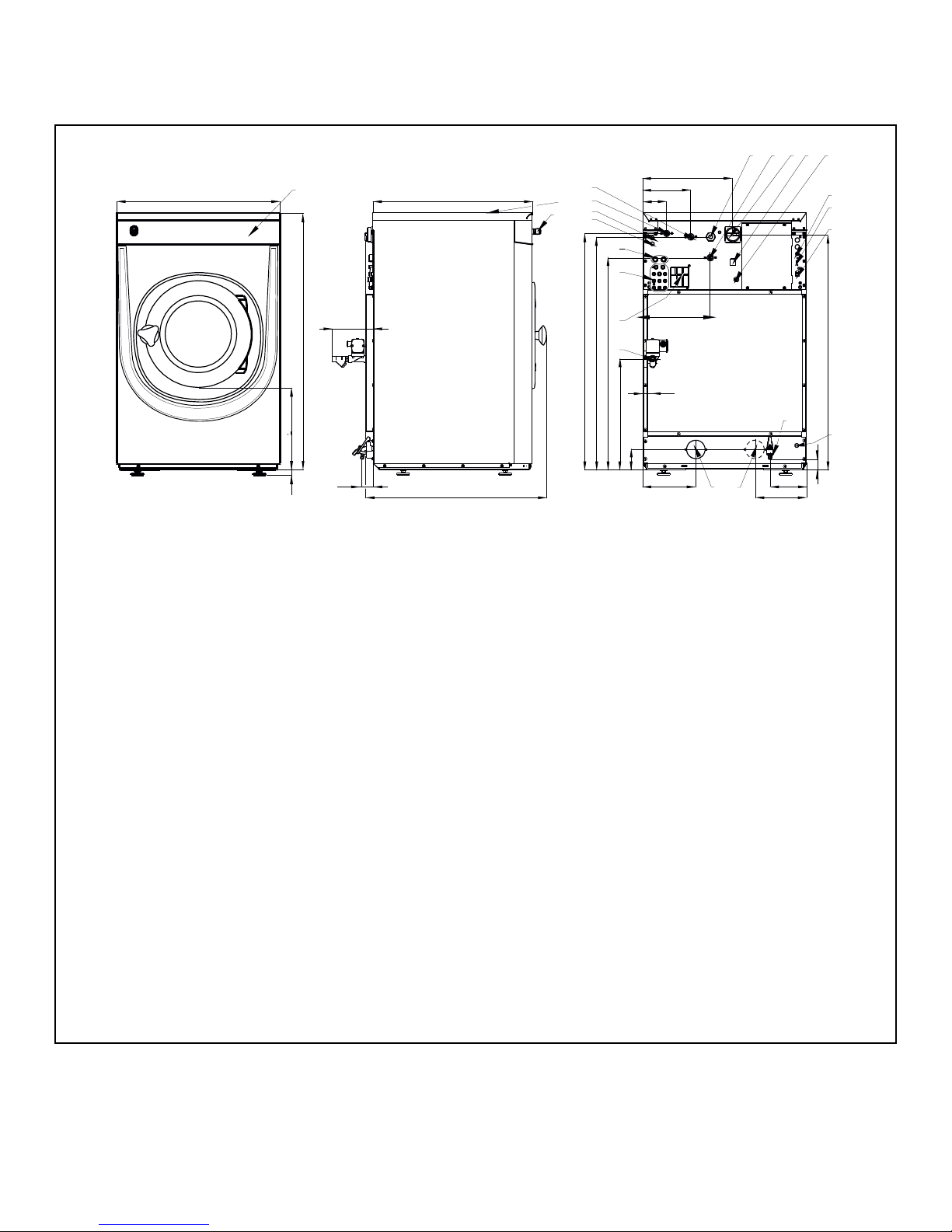
1
2
3
4
5
6
8
10
11
12
13
14 15
16
17
9
7
18
19
20
21
22
23
A
B
C
D
E
F
H
G
V
U
T
S
R
Q
O
M
P
N
L
J
K
I
W
CFD1224N
Specifications and Dimensions
Machine Dimensions
1. Control panel
2. Soap dispenser
3. Centralstop button
4. Steam connection
5. Air relieve
6. Liquid soap connection
7. Recyled water inlet
8. Steam valve connection
9. Recycled water valve cable inlet
10. Cold water inlet, soft
11. Cold water inlet, hard
12. Electrical connection
13. Hot water inlet
14. Main switch
15. Heating change-over switch
16. Liquid soap pump eletrical connection
17. Fuses
18. USB port
19. PC programming connection
20. Discharge water cable inlet
21. Drain valve - 3 in. [76 mm]
22. Drain valve or recycle valve - 3 in. [76 mm] (28 kg / 70 lb. / 280 L Models only)
23. Drain valve - 1/2", applicable for wash bath sample (on request only)
Figure 1
©
Copyright, Alliance Laundry Systems LLC -
DO NOT COPY or TRANSMIT
14 Part No. D1625ENR4
Page 15
Specifications and Dimensions
Specification
7 kg /
14 lb. /
65 L
Models,
in. [mm]
8 kg /
20 lb. /
80 L
Models,
in. [mm]
11 kg /
25 lb. /
105 L
Models,
in. [mm]
14 kg /
30 lb. /
135 L
Models,
in. [mm]
18 kg /
40 lb. /
180 L
Models,
in. [mm]
24 kg /
55 lb. /
240 L
Models,
in. [mm]
28 kg /
70 lb. /
280 L
Models,
in. [mm]
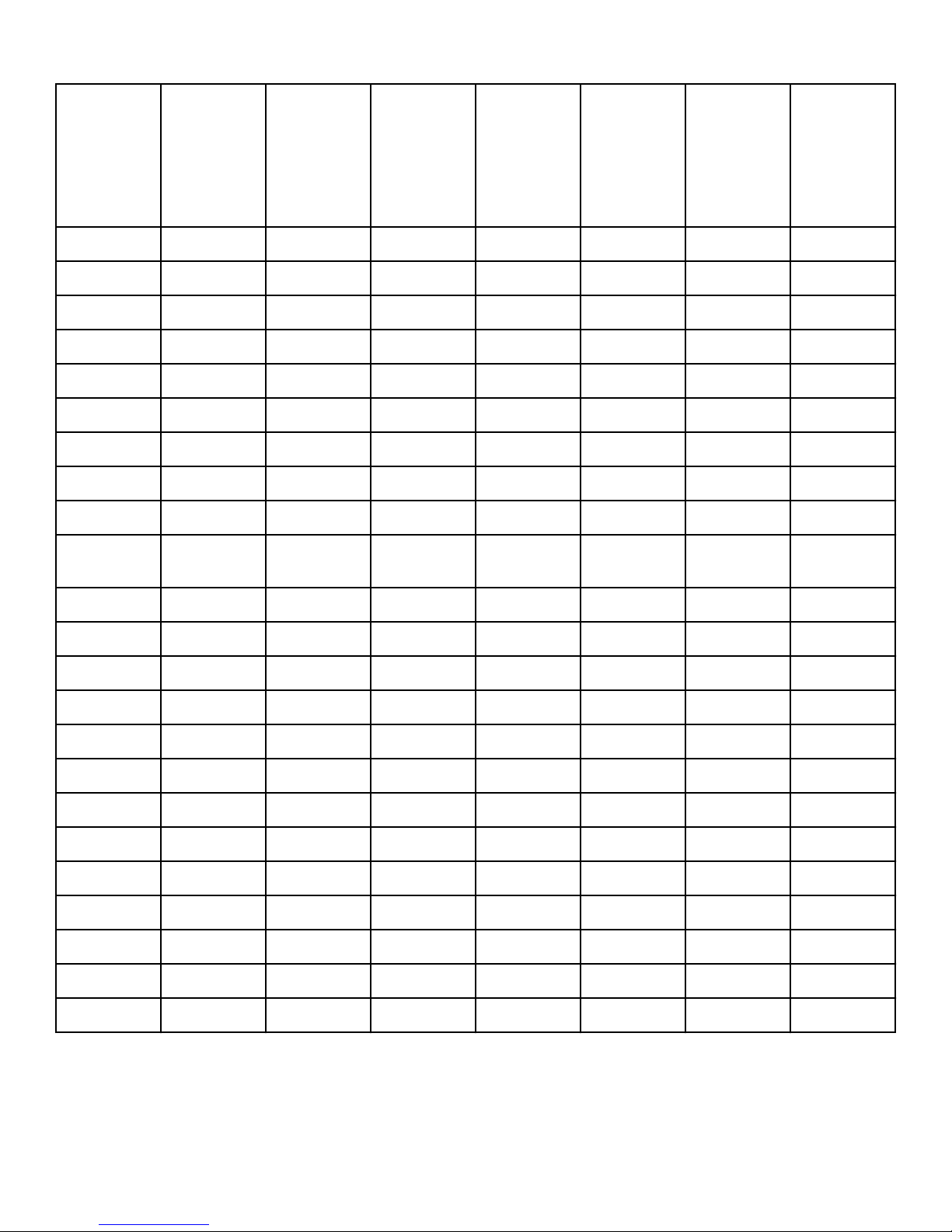
A 27.95 [710] 27.95 [710] 31.29 [795] 31.29 [795] 38.18 [970] 38.18 [970] 38.18 [970]
B 0.94 [24] 0.94 [24] 0.94 [24] 0.94 [24] 0.94 [24] 0.94 [24] 0.94 [24]
C 13.74 [349] 13.74 [349] 13.46 [342] 13.46 [342] 18.77 [477] 18.77 [477] 18.77 [477]
D 43.89 [1115] 43.89 [1115] 48.22 [1225] 48.22 [1225] 55.51 [1410] 55.51 [1410] 55.51 [1410]
E 7.08 [180] 7.08 [180] 7.08 [180] 7.08 [180] 3.54 [90] 3.54 [90] 3.54 [90]
F 1.89 [48] 1.89 [48] 1.89 [48] 1.89 [48] 1.89 [48] 1.89 [48] 1.89 [48]
G 29.13 [740] 31.10 [790] 31.29 [795] 37.20 [945] 38.18 [970] 43.50 [1105] 46.65 [1185]
H 25.51 [648] 27.48 [698] 27.48 [698] 33.39 [848] 34.57 [878] 39.88 [1012] 42.83 [1088]
I 40.11 [1019] 40.35 [1025] 44.68 [1135] 44.68 [1135] 51.96 [1320] 51.96 [1320] 51.96 [1320]
J 39.52 [1004] 39.76 [1010] 44.09 [1120] 44.09 [1120] 51.08
[1297.5]
51.08
[1297.5]
51.37 [1305]
K 35.98 [914] 36.22 [920] 40.55 [1030] 40.55 [1030] 47.83 [1215] 47.83 [1215] 47.83 [1215]
L 18.89 [480] 18.89 [480] 19.92 [506] 19.92 [506] 19.29 [490] 19.29 [490] 19.29 [490]
M 3.22 [82] 3.46 [88] 3.46 [88] 3.46 [88] 4.27 [108.5] 4.27 [108.5] 4.27 [108.5]
N 9.05 [230] 9.05 [230] 9.05 [230] 9.05 [230] 10.62 [270] 10.62 [270] 10.62 [270]
O 7.99 [203] 7.99 [203] 7.99 [203] 7.99 [203] 7.99 [203] 7.99 [203] 7.99 [203]
P N/A N/A N/A N/A N/A N/A 10.79 [274]
Q 2.64 [67] 2.64 [67] 2.64 [67] 2.64 [67] 2.64 [67] 2.64 [67] 2.64 [67]
R 40.15 [1020] 40.15 [1020] 44.48 [1130] 44.48 [1130] 51.77 [1315] 51.77 [1315] 51.77 [1315]
S 1.65 [42] 1.65 [42] 1.65 [42] 1.65 [42] 3.14 [80] 3.14 [80] 3.14 [80]
T 11.53 [293] 11.53 [293] 11.53 [293] 11.53 [293] 11.53 [293] 11.53 [293] 11.53 [293]
U 15.35 [390] 15.35 [390] 18.70 [475] 18.70 [475] 24.01 [610] 24.01 [610] 24.01 [610]
V 8.58 [218] 8.58 [218] 8.58 [218] 8.58 [218] 8.58 [218] 8.58 [218] 8.58 [218]
W 4.44 [113] 4.44 [113] 4.44 [113] 4.44 [113] 4.44 [113] 4.44 [113] 4.44 [113]
Table 1
©
Copyright, Alliance Laundry Systems LLC -
DO NOT COPY or TRANSMIT
15 Part No. D1625ENR4
Page 16
J
B
A
F
E
I
D
H
C
G
K
1
2
3
CFD1209N
Specifications and Dimensions
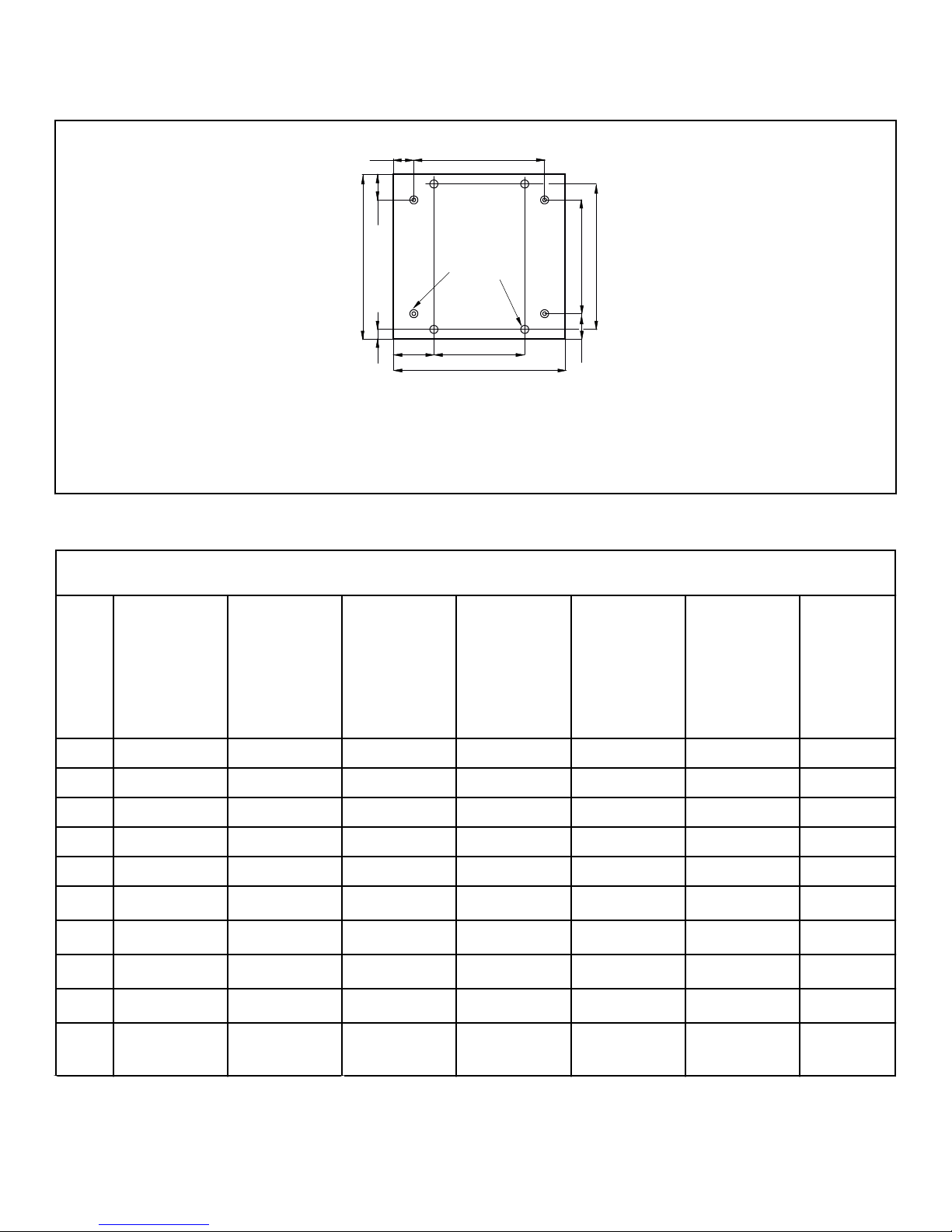
Mounting Bolt Hole Locations
1. Front of machine
2. Position of the leveling leg
3. Drilling point
Figure 2
Mounting Bolt Hole Locations, in. [mm]
Sp
eci
fica
tio
n
7 kg /
14 lb. /
65 L Models
8 kg /
20 lb. /
80 L Models
11 kg /
25 lb. /
105 L
Models
14 kg /
30 lb. /
135 L
Models
18 kg /
40 lb. /
180 L
Models
24 kg /
55 lb. /
240 L
Models
28 kg /
70 lb. /
280 L
Models
A 20.86 [530] 20.86 [530] 24.33 [618] 24.33 [618] 30.90 [785] 30.90 [785] 30.90 [785]
B 15.51 [394] 17.48 [444] 17.48 [444] 22.20 [564] 22.04 [560] 27.36 [695] 30.31 [770]
C 3.54 [90] 3.54 [90] 3.48 [88.5] 3.48 [88.5] 3.64 [92.5] 3.64 [92.5] 3.64 [92.5]
D 5.09 [129.5] 5.09 [129.5] 5.09 [129.5] 6.27 [159.5] 8.32 [211.5] 8.32 [211.5] 8.32 [211.5]
E 14.76 [375] 14.76 [375] 17.91 [455] 20.27 [515] 26.37 [670] 26.37 [670] 26.37 [670]
F 6.59 [167.5] 6.59 [167.5] 6.69 [170] 5.51 [140] 5.90 [150] 5.90 [150] 5.90 [150]
G 1.57 [40] 1.57 [40] 1.37 [35] 2.36 [60] 1.96 [50] 1.96 [50] 1.96 [50]
H 4.64 [118] 4.64 [118] 4.64 [118] 4.64 [118] 3.94 [100] 3.94 [100] 3.94 [100]
I 27.95 [710] 27.95 [710] 31.29 [795] 31.29 [795] 38.18 [970] 38.18 [970] 38.18 [970]
J 25.25 [641.5] 27.22 [691.5] 27.22 [691.5] 33.12 [841.5] 34.31 [871.5] 39.62 [1006.5] 42.60
©
Copyright, Alliance Laundry Systems LLC -
DO NOT COPY or TRANSMIT
Table 2 continues...
[1082]
16 Part No. D1625ENR4
Page 17
Specifications and Dimensions
Mounting Bolt Hole Locations, in. [mm]
Sp
eci
fica
tio
n
7 kg /
14 lb. /
65 L Models
8 kg /
20 lb. /
80 L Models
11 kg /
25 lb. /
105 L
Models
14 kg /
30 lb. /
135 L
Models
18 kg /
40 lb. /
180 L
Models
24 kg /
55 lb. /
240 L
Models
28 kg /
70 lb. /
280 L
Models
K 21.65 [550] 23.62 [600] 24.02 [610] 26.77 [680] 25.98 [660] 31.30 [795] 34.25 [870]
Table 2
©
Copyright, Alliance Laundry Systems LLC -
DO NOT COPY or TRANSMIT
17 Part No. D1625ENR4
Page 18
CHM2466N_SVG
A
B
Specifications and Dimensions
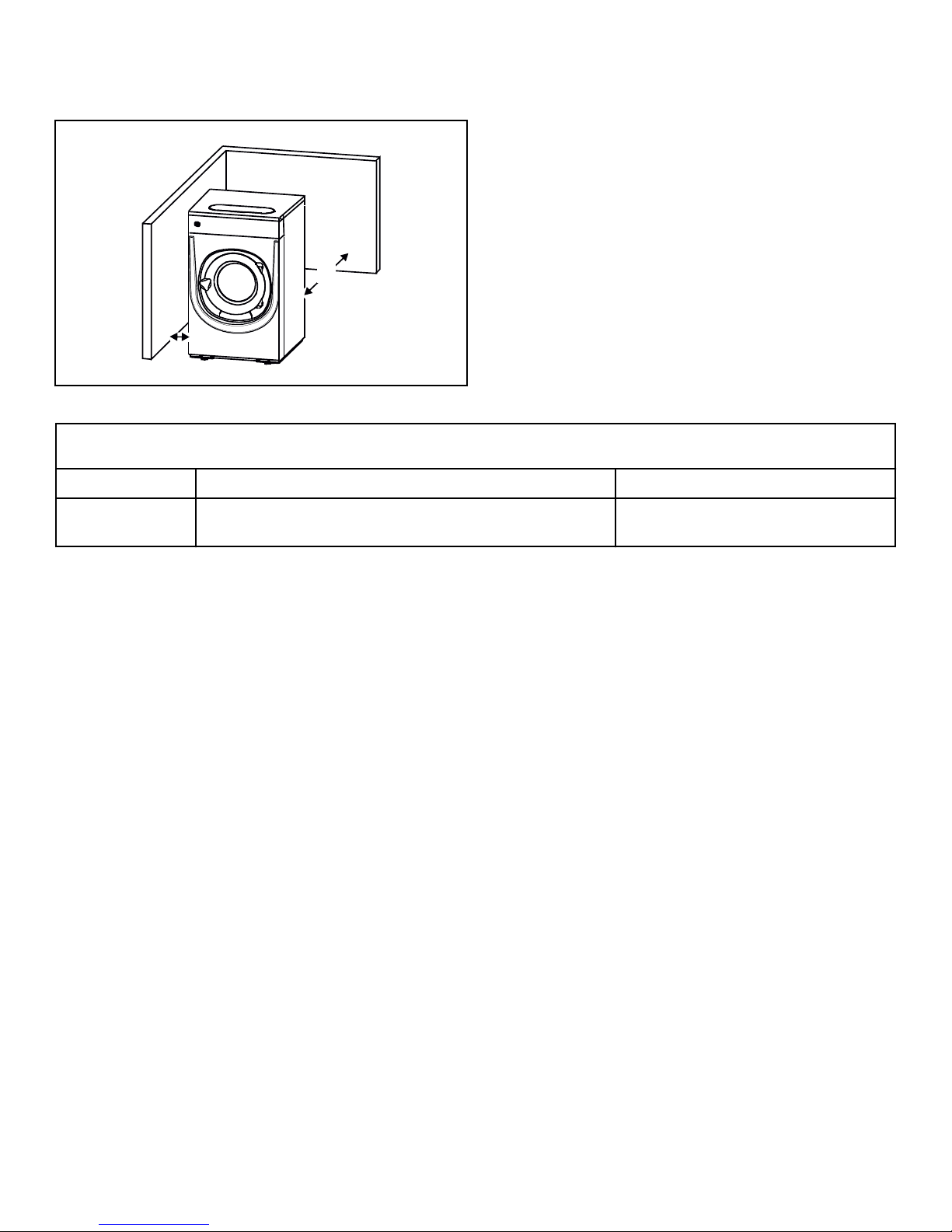
Floor Mounting Layout
Dimensional Clearances
Figure 3
Dimensional Clearances, in. [mm]
A Distance to wall (minimum) 20 [500]
B Distance of machine to side wall or other machine (mini-
mum)
Table 3
0.79 [20]
©
Copyright, Alliance Laundry Systems LLC -
DO NOT COPY or TRANSMIT
18 Part No. D1625ENR4
Page 19
Installation
2
1
3
CFD1208N
Installation
Pallet Removal
The machine is delivered bolted onto the transport pallet and
packed in shrink-wrap foil or box.
1. Remove packing from machine.
2. Remove front and rear panel.
3. Remove bolts between machine and pallet.
4. Mount front and rear panel.
5. When machine is lifted off pallet, make sure the machine does
not come down on the floor with either of the rear corners
first. The machine's side panel can be damaged.
NOTE: Two self-adhesive ruber stop-blocks are supplied with the machine. They may be applied as
paint protection when opening the door.
6. Mount leveling legs.
7. Level machine with feet of the machine.
WARNING
It is of utmost importance that the machine is
placed level, from side to side as well as front to
back. If the machine is not properly leveled, it
may result in out-of-balance error without a real
out of balance in the drum.
W913
8. Recheck the setting of the safety switch, refer to Every 6
Months.
Mounting Bolt Installation (If Required)
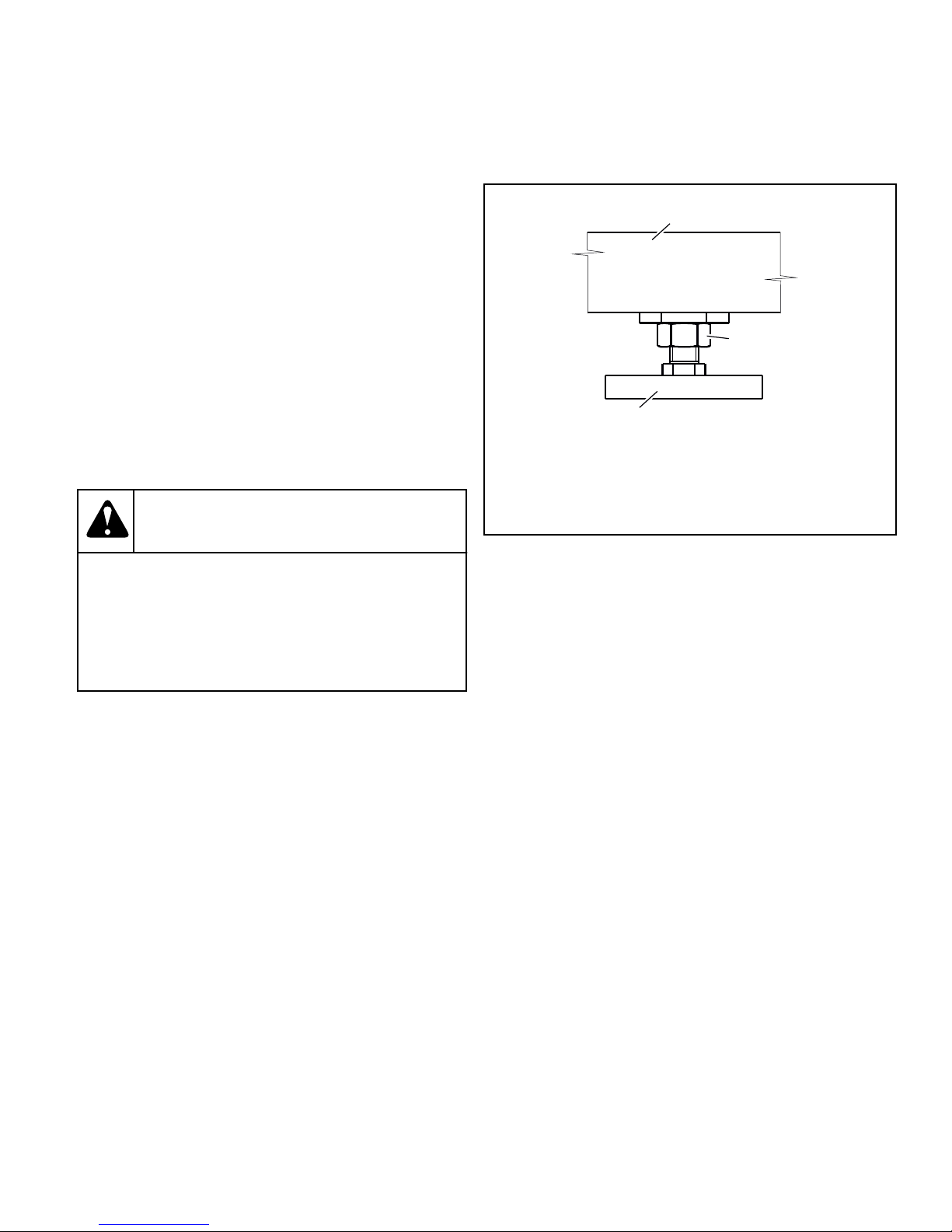
NOTE: After leveling is complete, tighten the nut securely against the machine's base. Refer to Figure 4 .
1. Machine
2. Nut
3. Leveling Leg
Figure 4
5. Mount the anchoring bolts in the holes drilled in the floor.
6. Position washers and locknuts on machinery anchor bolts and
finger-tighten to machine base.
NOTE: If necessary, prop up the machine frame so
that not deformation occurs during the tightening of
the anchoring bolts.
7. Remove the shipping braces which secure the moving components of the machine during shipping. Refer to Shipping
Brace Removal.
Machines do not have to be mounted by means of anchoring
bolts. If anchoring is necessary, perform the following steps:
1. Drill 2 holes for the anchoring bolts, refer to Figure 4 . Hole
diameter in machine's base is 0.63 in. [16 mm] .
2. Place the machine adjacent to the foundation. Do not attempt
to move it by pushing on the sides. Always use the bottom of
the frame of the washer-extractor to lift and move the whole
machine.
3. Place the machine carefully over the two drilled holes.
4. Check that the machine is seated in a perfectly level manner.
Adjust leveling legs as needed.
©
Copyright, Alliance Laundry Systems LLC -
DO NOT COPY or TRANSMIT
19 Part No. D1625ENR4
Page 20
34
2 1
CFD1225N
Installation
Shipping Brace Removal
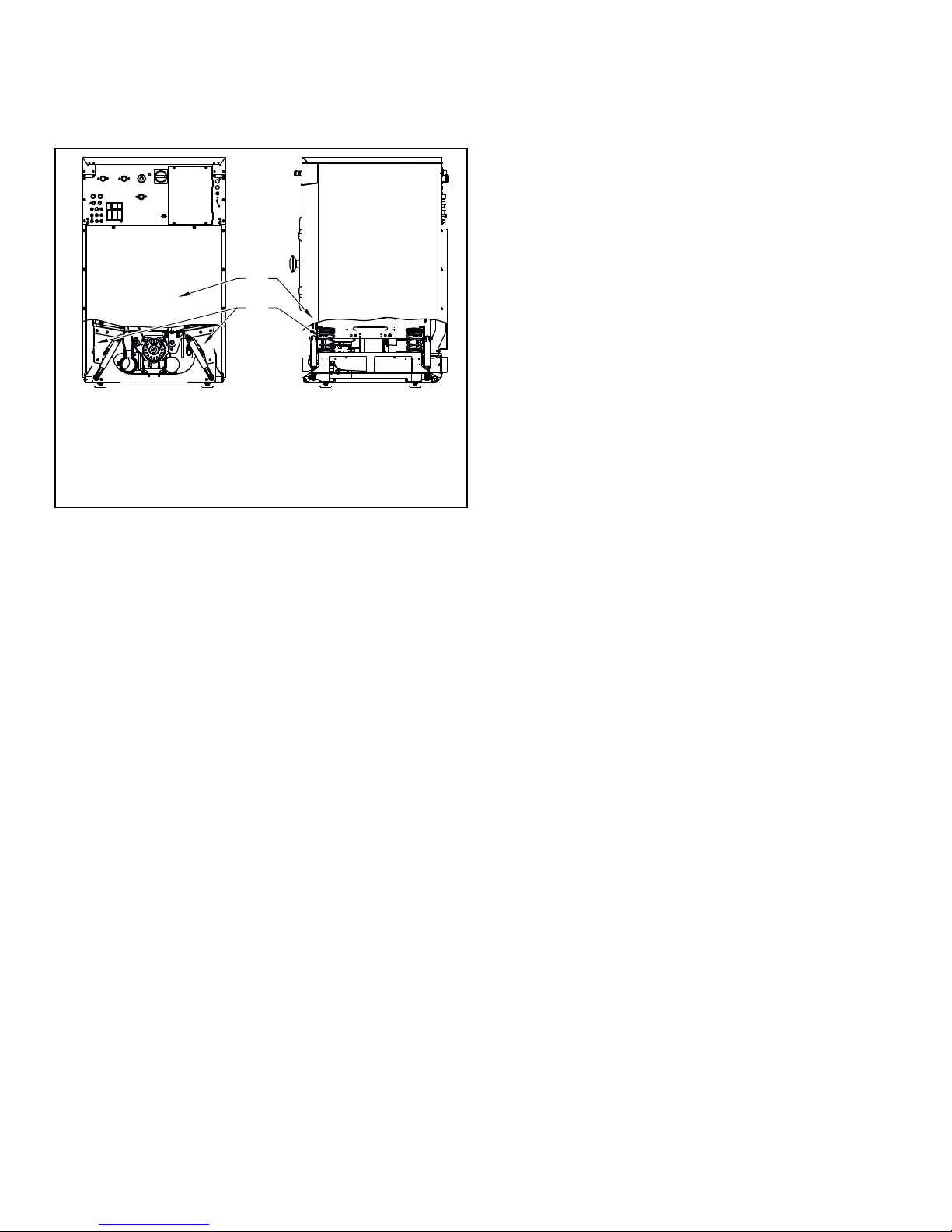
1. Remove front and rear panel, refer to Figure 5 .
1. Front transport holder
2. Rear transport holder
3. Front panel
4. Rear panel
Figure 5
2. Remove both front metal transport holders.
3. Remove both rear transport holders.
IMPORTANT: The machine may not be moved with
the shipping braces removed. Save the shipping
braces for future use.
©
Copyright, Alliance Laundry Systems LLC -
DO NOT COPY or TRANSMIT
20 Part No. D1625ENR4
Page 21
Machine Installation
5
6
7
7
1
3
4
8
1
2
2
CFD1226N
Install the machine close to a floor drain or open drain.
Elevated Base Frame Installation with
Existing Floor
The elevated base frame structure must be able to withstand the
static and dynamic loads of the machine floor (refer to General
Specifications), and it must allow the machine to be seated in a
perfectly level manner.
Install the machine on a base without adjustable feet.
Weighing System Installation - 18 kg -
28 kg / 40 lb. - 70 lb. / 180 - 280 L Models
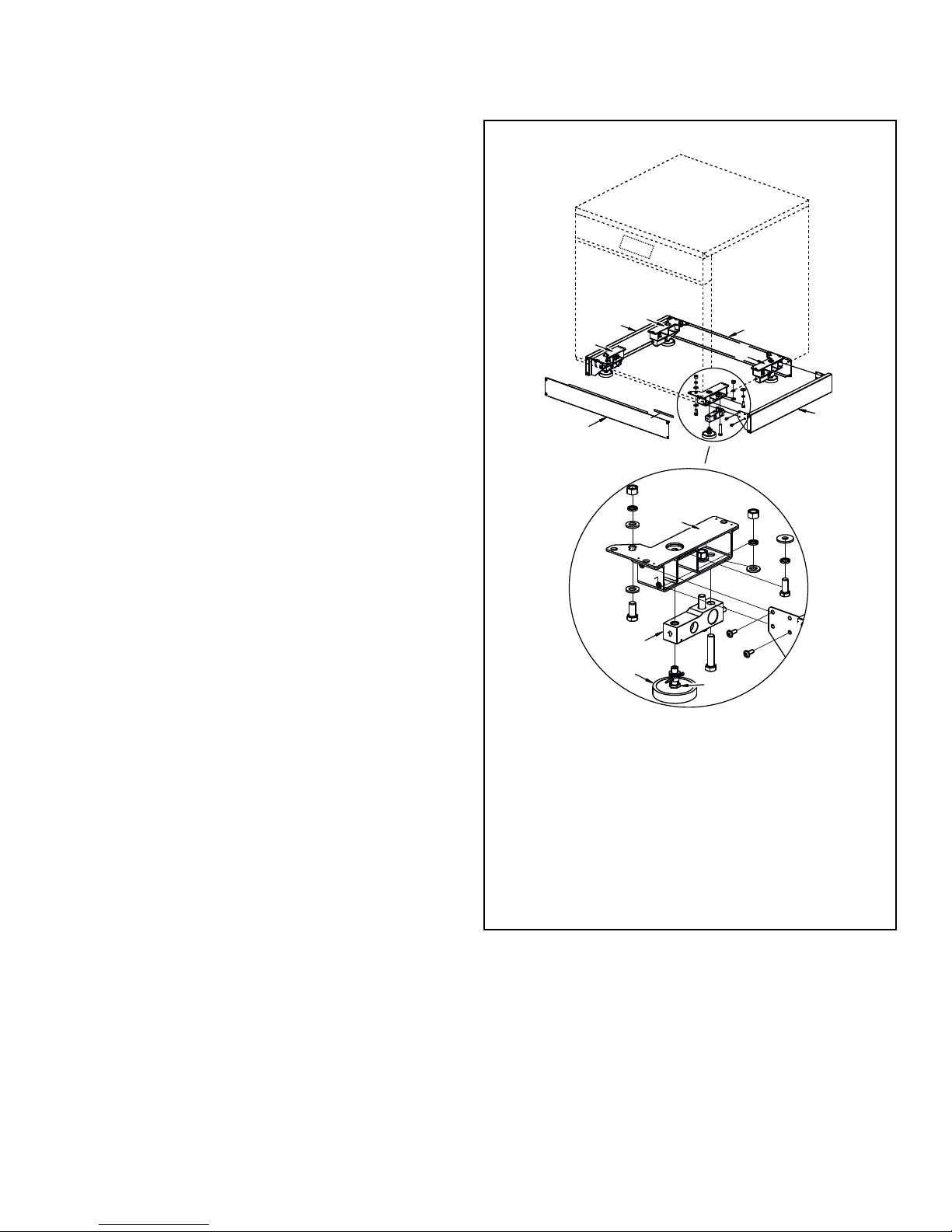
1. Lift up the machine.
2. Install two left load sensor supports and two right load sensor
supports to the machine frame. Refer to Figure 6 .
Installation
1. Load sensor support
2. Load sensor support
3. Load sensor
4. Leveling leg
5. Cover
6. Cover
7. Cover
8. Nut
Figure 6
3. Install load sensors with their rubber leveling legs on to the
supports.
4. Check that all the supports and load sensors with rubber leveling legs are correctly placed on the machine frame and tightened.
5. Place the machine in the required position.
6. Check that all the rubber leveling legs of the load sensors are
stable.
©
Copyright, Alliance Laundry Systems LLC -
DO NOT COPY or TRANSMIT
21 Part No. D1625ENR4
Page 22
CHM2480N_SVG
1
Installation
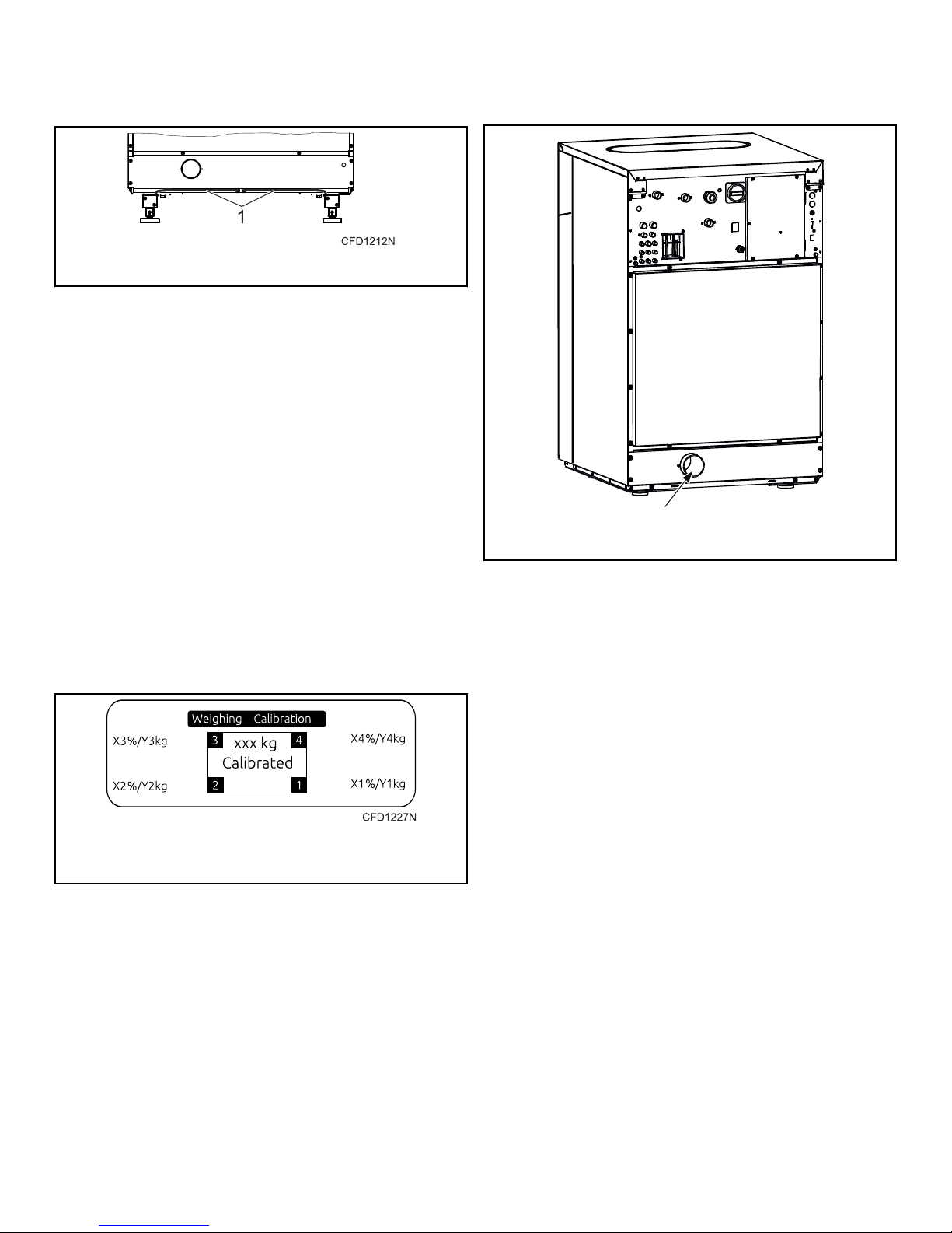
7. Fit the sensor cables into the prepared openings with cable
fixtures. Refer to Figure 7 .
1. Sensor cable openings
Figure 7
8. Remove the transport safety devices (transport props).
9. Use a water-level to check that the lower frame of machine is
positioned totally level.
10. Attach hoses for water supply to the machine.
NOTE: The machine is not anchored into the floor; it
stands on the load sensor feet. Take into consideration that the entire machine acts as a measuring
gauge. Therefore, anything that you place on to the
machine or anything that is in physical contact with
it influences the weighing process. Make sure that
the water connection, as regards the pressure in the
hoses, does not interfere with the weighing. The hoses must no pull or push the machine in any direction or prop it up in any way.
11. Install the covers. Refer to Figure 6 .
12. Check and, if necessary, adjust the height of the load sensor
feet so that an even load distribution among all the load sensors is ensured. Refer to Figure 8 .
Drain Connection
1. Drain connection
Figure 9
1. X1, X2, X3, X4 - range must be within 10-40%
2. Y1, Y2, Y3, Y4 - load of each load sensor in kg
Figure 8
13. If the load sensors are outside of the specified range, it is necessary to adjust the leveling legs of load sensors. Each load
sensor leveling leg can be adjusted within the range of 0.2 in.
[5 mm].
a. Lift up the machine.
b. Loosen the nut and turn the level leg in order to achieve
the required position.
c. Tighten the nut.
d. Put the machine down and verify that the load applied to
each sensor is within the specified range.
©
Copyright, Alliance Laundry Systems LLC -
DO NOT COPY or TRANSMIT
22 Part No. D1625ENR4
Page 23
Drain Valve
CHM2479N_SVG
A
4
D
C
3
B
2
1
IMPORTANT: Machine must be installed in accordance
with all local codes and ordinances.
All drain systems must be vented to prevent an air lock or siphoning.
Installation
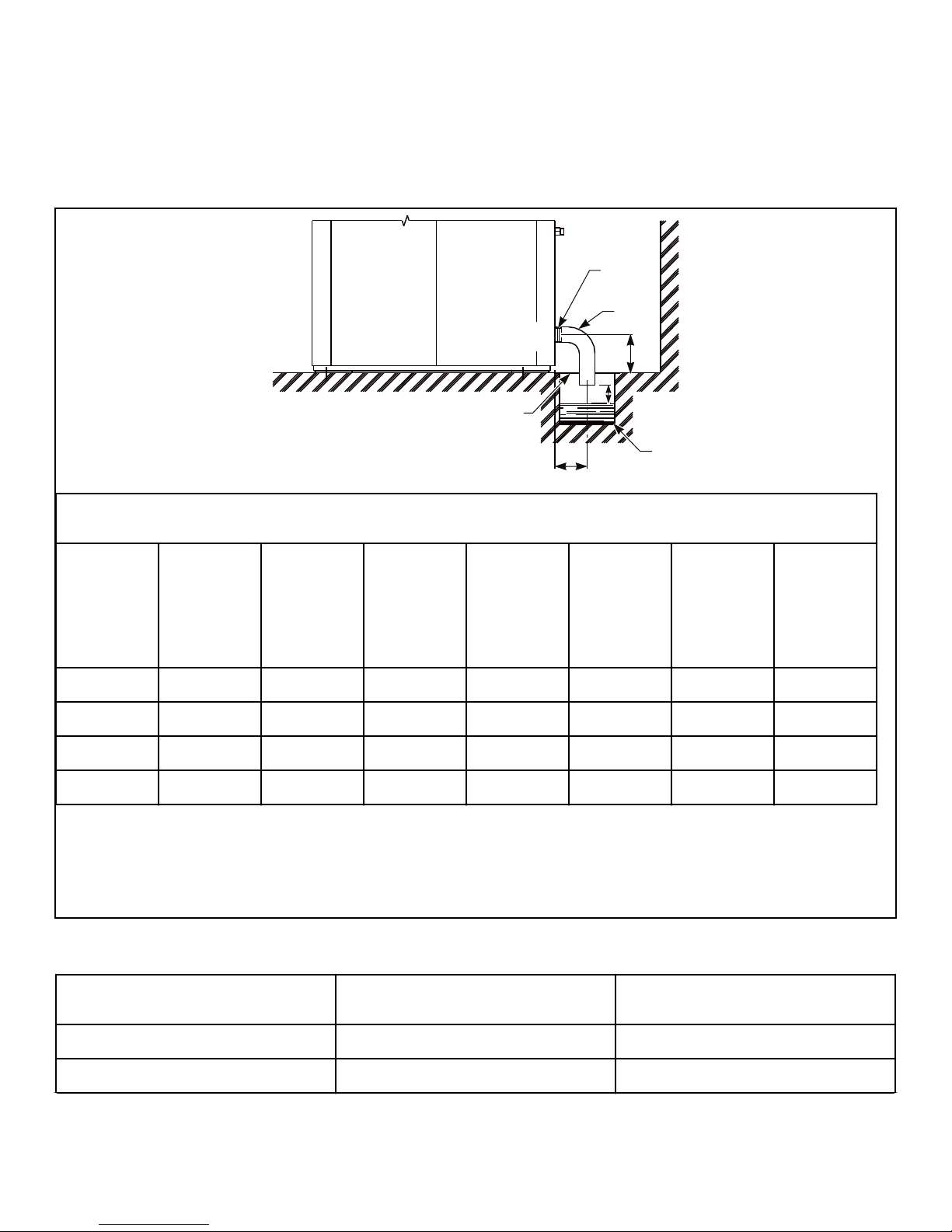
Connect a 3 inch [76 mm] pipe or rubber hose to the machine's
drain pipe, ensuring a downward flow from the machine. Avoid
sharp bends which may prevent proper draining.
The drainage pipe should be located over a floor drain, drainage
channel.
Drainage Pipe Information, in. [mm]
Specification
7 kg /
14 lb. /
65 L
Models
8 kg /
20 lb. /
80 L
Models
11 kg /
25 lb. /
105 L
Models
14 kg /
30 lb. /
135 L
Models
18 kg /
40 lb. /
180 L
Models
24 kg /
55 lb. /
240 L
Models
28 kg /
70 lb. /
280 L
Models
A 3 [75] 3 [75] 3 [75] 3 [75] 3 [75] 3 [75] 3 [75]
B 4.17 [106] 4.4 [112] 4.4 [112] 4.4 [112] 5.21 [132.5] 5.21 [132.5] 5.21 [132.5]
C minimum 0.79 [20] 0.79 [20] 0.79 [20] 0.79 [20] 0.79 [20] 0.79 [20] 0.79 [20]
D minimum 3.94 [100] 3.94 [100] 3.94 [100] 3.94 [100] 3.94 [100] 3.94 [100] 3.94 [100]
1. Clamp
2. Drain elbow 3 in. [76 mm]
3. Waste channel
4. Waste channel cover
Figure 10
Specification Model Requirement
Drain connection number All 1
Drain connection size, in. [mm] All 3 [76]
©
Copyright, Alliance Laundry Systems LLC -
DO NOT COPY or TRANSMIT
Table 4 continues...
23 Part No. D1625ENR4
Page 24
CHM2481N_SVG
2
C
B
A
1
Installation
Specification Model Requirement
Average flow rate of draining gal/min. [l/
All 55.48 [210]
min.]
Drain pump with hose - internal diameter
of hose, in [mm]
7 kg - 8 kg /
14 lb. - 20 lb. /
65 L - 80 L
Flow rate of drain pump, gal/min. [l/
min.]
7 kg - 8 kg /
14 lb. - 20 lb. /
65 L - 80 L
Table 4
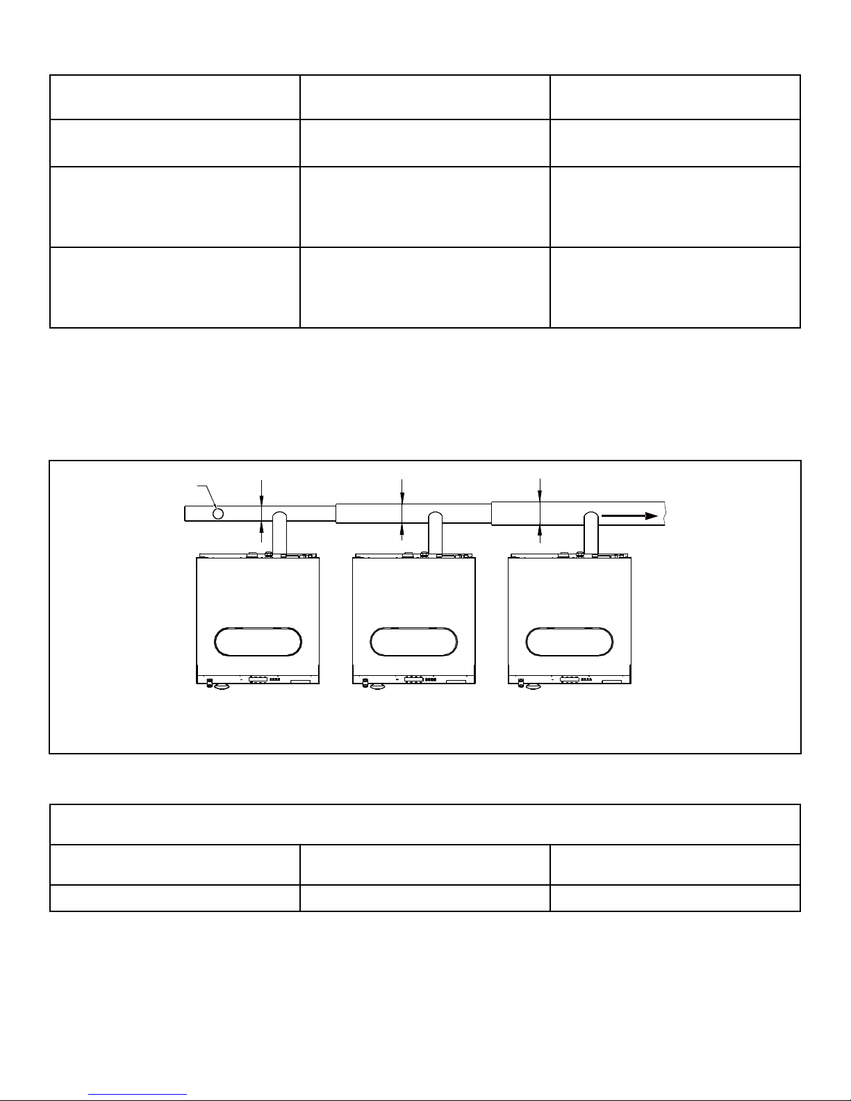
The main drain channel-pipe must have the capacity to be able to
handle the total output of all connected machines. In a drainpipe,
a vent must be provided every 65.62 ft. [20 m] to assure the drain
pipe will work. If the main drain pipe cannot be sufficiently vented, install a vent per machine. Every time a machine is coupled
0.75 [19]
9.51 [36]
on the drainpipe, the diameter of the tube or the width of the
waste channel must increase. Refer to Figure 11 .
The diameters of drain pipe for machines with two drain valves
must have dimensions suitable for double the value of water flow.
1. Vent
2. Flow
Drain Line Sizing / Minimum Drain ID, in. [mm]
3 [75] 4 [100] 5 [125]
©
Copyright, Alliance Laundry Systems LLC -
DO NOT COPY or TRANSMIT
A - 1 Machine B - 2 Machines C - 3 Machines
Figure 11
Table 5
24 Part No. D1625ENR4
Page 25
CHM2482N_SVG
1
Installation
Drain Pump, 7 kg - 8 kg / 14 lb. - 20 lb. / 65 L - 80 L
Models
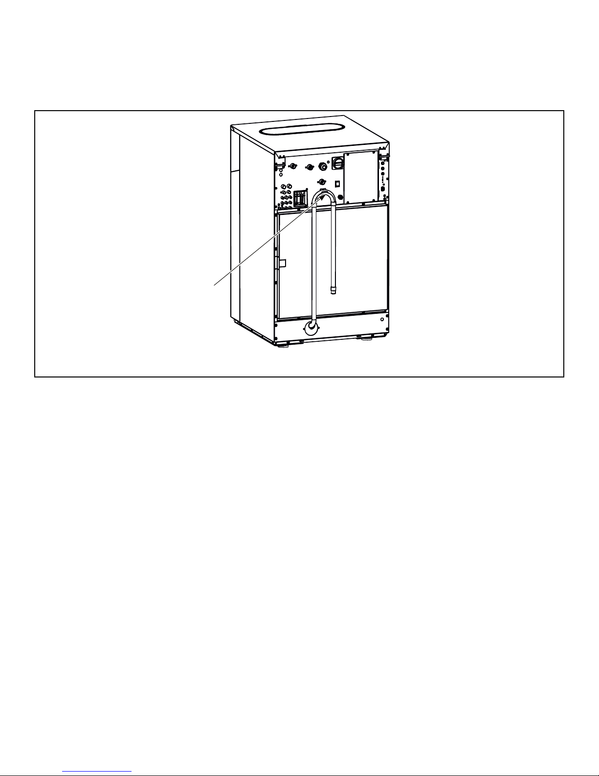
Connect a flexible hose to a drain pipe so that the hose bend must
not be located lower than the water level to provide sufficient si-
phon effect. In order to achieve good draining, the hose must not
bend at a sharp angle. Refer to Figure 12 .
1. Drain hose bend
Figure 12
©
Copyright, Alliance Laundry Systems LLC -
DO NOT COPY or TRANSMIT
25 Part No. D1625ENR4
Page 26
CHM2503N_SVG
1
2
CHM2475N_SVG
21
CHM2476N_SVG
3
2
1
Installation
Water Connection Requirements
WARNING
To prevent personal injury, avoid contact with inlet
water temperatures higher than 125° Fahrenheit [51°
Celsius] and hot surfaces.
NOTE: North American Models: Water inlet hose with
notches should be connected to the water supply faucet, while the side of the water inlet hose without
notches should be connected to the water inlet valves.
Refer to Figure 13 .
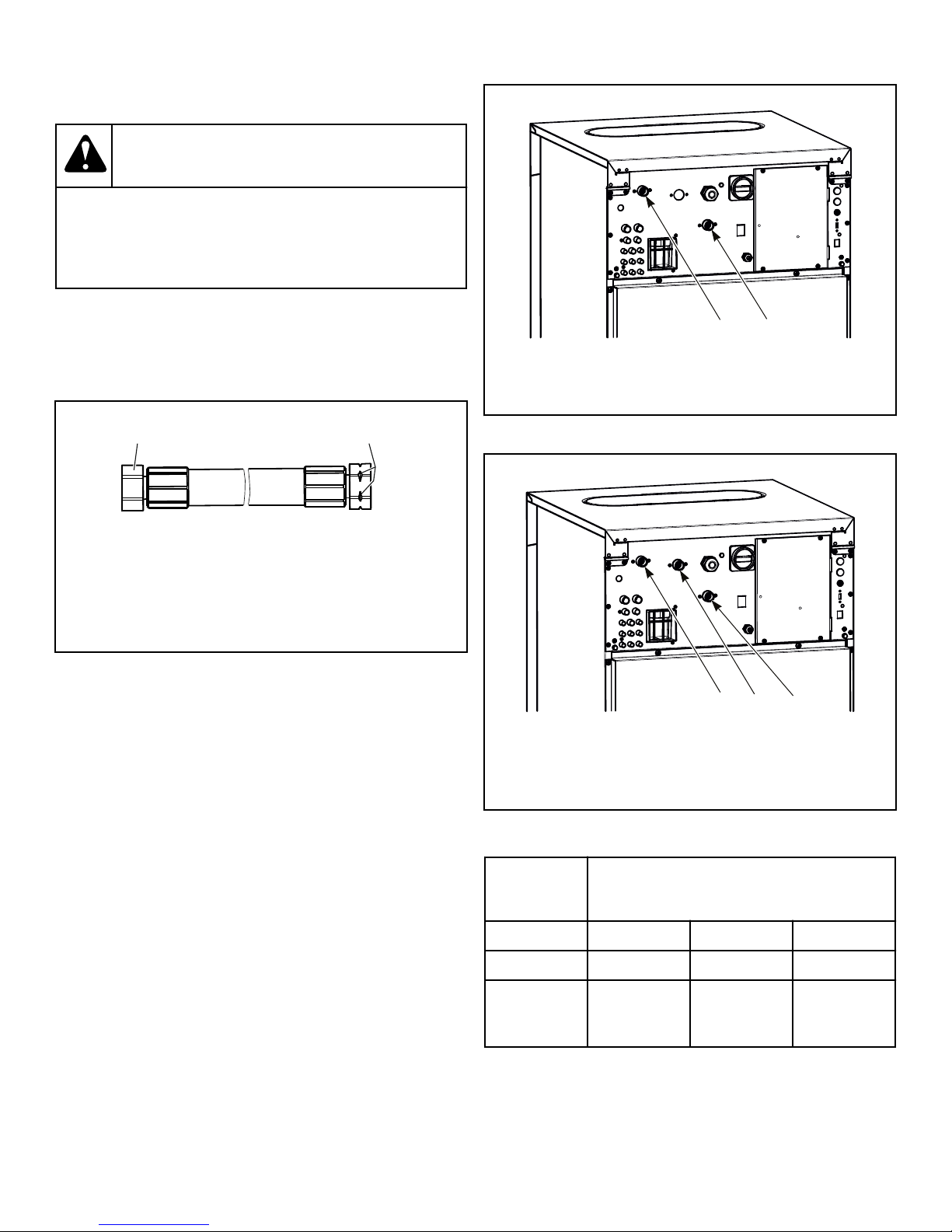
2 Water Connection Models
W748
1. Refer to Table 6 .
2. Refer to Table 6 .
Figure 14
3 Water Connection Models
1. Water inlet valve connection (hose connection without
notch)
2. Water supply faucet connection (hose connection with
notch)
Figure 13
NOTE: Models outside of North America: For 7 kg / 14
lb. / 65 L, 8 kg / 20 lb. / 80 L, 11 kg / 25 lb. / 105 L, 14 kg /
30 lb. / 135 L, 18 kg / 40 lb. / 180 L and 24 kg / 55 lb. /
240 L Models, to connect cold water, use a hose with
plastic elbow. To connect hot water, use a hose with
metal elbow.
Do not re-use water hoses; only use new water hoses.
The appliance has been designed with a built-in "AB" airgap system according to EN1717. Nevertheless, when potable water will
be connected to the appliance, an approved double check valve or
some other no less effective device providing backflow prevention protection to at least fluid category three shall be fitted at the
point of connections between the water supply and the appliance.
All intake connections to the machine are to be fitted with manual shut-off valves and filters, to facilitate installation and servicing.
All water connectors present on the machine must be connected
or the wash program will not function correctly. Refer to Table 6
for possible connection options, which will depend on the water
types to be connected to the machine, which can be found by
checking the machine plates.
1. Refer to Table 6 .
2. Refer to Table 6 .
3. Refer to Table 6 .
Figure 15
Water
type Water connection
1 2 3
Cold and Hot Cold Hot N/A
Cold soft,
Cold soft Hot Cold hard
Cold hard and
Hot
Table 6
©
Copyright, Alliance Laundry Systems LLC -
DO NOT COPY or TRANSMIT
26 Part No. D1625ENR4
Page 27
Connections should be supplied by a hot and a cold water line per
WARNING
national and local codes and in accordance with IEC 61770.
To connect water service to a machine with hoses, use the follow-
If the water pressure is below the minimum value,
the wash result can not be guaranteed for a selected
program.
W914
ing procedure:
1. Before installing hoses, flush the building’s water system at
the machine connection valves for at least two (2) minutes.
2. Check filters in the machine’s inlet hoses for proper fit and
cleanliness before connecting.
The maximum water inlet temperature for vended models is
194°F [90°C]and the recommended maximum water inlet temperature for on-premises models is 150°F [66°C] (standard models) or 140°F [60°C] (WRAS approved models) .
3. Hang hoses in a large loop; do not allow them to kink.
If additional hose lengths are needed or using hoses other than
those supplied by manufacturer, flexible hoses with screen filters
are required.
Connections should be supplied by a hot and a cold water line of
at least the sizes shown in Water Supply Line Sizing . Installation
of additional machines will require proportionately larger water
lines.
Specification Model Requirement
Water inlet connection size, in. BSP All 3/4
Installation
Recommended pressure, PSI [bar] All 44-73 [3-5]
Inlet flow capacity per inlet, gal/min [l/
min.]
7 kg - 24 kg /
14 lb. - 55 lb. /
5.28 [20]
65 L - 240 L
Inlet flow capacity per inlet, gal/min at
15 PSI [l/min. at 1 bar]
18 kg - 28 kg /
40 lb. - 70 lb. /
17.44 [66]
180 L - 280 L
Inlet flow capacity per inlet, gal/min at
116 PSI [l/min. at 8 bar]
18 kg - 28 kg /
40 lb. - 70 lb. /
49.66 [188]
180 L - 280 L
Table 7
Suitable air cushions (risers) should be installed in supply lines to
prevent “hammering.”
Alliance Laundry Systems, LLC ranges of front loading commercial clothes washing machines have solenoid valves at the inlets.
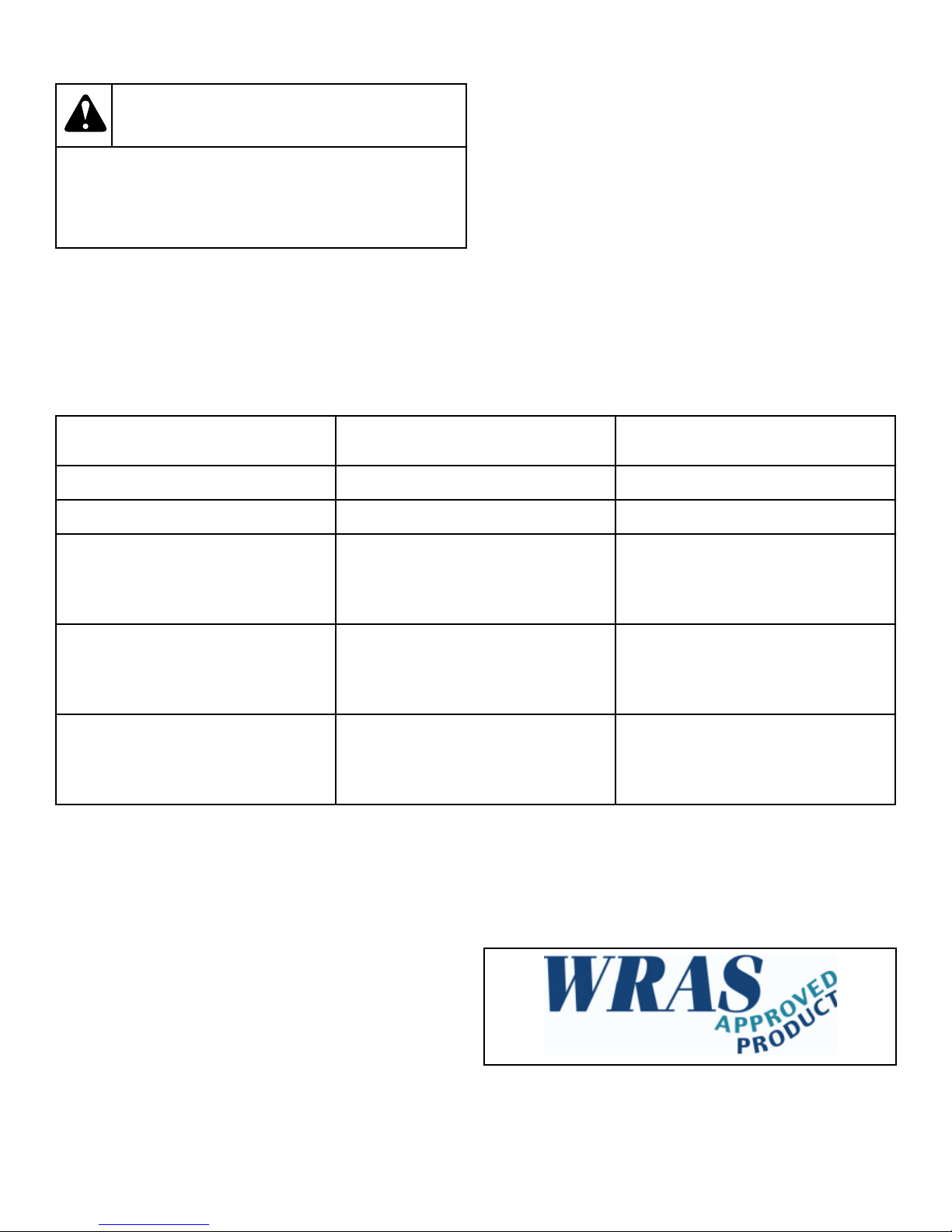
the watermark is provided with the unit and must be fitted at the
point of connection(s) between the supply and the fitting.
NOTE: No more than two (2) water connection hoses
should be used on WRAS-approved models.
The water supply to the washing machines is supplied with an
AB air gap between the soap tray and the drum. Minimum and
maximum working pressure 1 bar and 8 bar. The machines are
supplied with approved inlet hoses.
NOTE: This machine has a fluid category 5 backflow
prevention device built in between the soap tray and
drum.
To comply with WRAS (IRN R150), European standard EN1717,
an approved double check valve backflow prevention device with
©
Copyright, Alliance Laundry Systems LLC -
DO NOT COPY or TRANSMIT
Figure 16
27 Part No. D1625ENR4
Page 28
CHM2477N_SVG
2
1
Installation
Water Reuse Connection
WARNING
Disconnect the machine power supply. When the
main switch is turned off, the inlet terminals of the
machine main switch are still under current.
W900
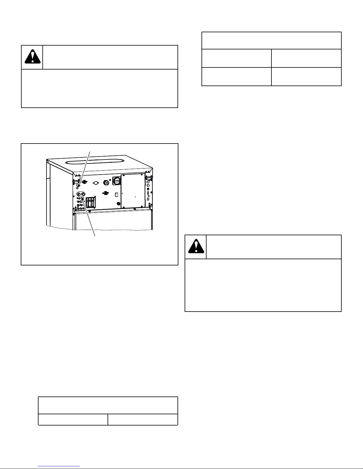
1. Drill out the protective screens of the water reuse inlet using a
drill bit of .59 in. [15 mm] diameter. Refer to Figure 17 .
IMPORTANT: Do not pierce the screens open. It
could lead to blockage of the water channel.
Water Reuse Specifications
Maximum pressure, PSI
116 [8]
[bar]
Connection - outside diam-
0.75 [19]
eter, in. [mm]
The hose and the connector must be resistant to chemical sub-
stances which are used for the washing process. It is also possible
to use a hose with enhanced performance such as the rubber
EPDM hose.
The water reuse system must be fitted with a filter which must be
regularly and thoroughly cleaned (based on water quality). This
cleaning prevents prolongation of filling up times and malfunc-
tion of water valves.
Reused Water Treatment
The reused water must be filtered before entering the water reuse
tank. A mechanical filter must be installed which filters off small
particles (fluff, buttons, paper, etc.) of sizes 0.0079 in. [0.2 mm]
or smaller. The denser the mesh, the better. There must also be a
filter installed on the pressure side of the pump. It is also possible
to install an additional, chemical filter. The manufacturer advises
to consult a specialist in filter systems.
1. Cable inlet for control of water reuse valve or pump
2. Water reuse inlet
Figure 17
2. Connect the control of your reuse valve or pump onto the con-
ductor of inlet valve I5 or I7 provided by the manufacturer,
which will disconnect the valve in question from standard
function.
IMPORTANT: The manufacturer waives all responsibility for malfunction of the washing machine if a
different valve than the specified I5 or I7 is used as
the water recycle valve.
3. Fit a cable bushing into the opening, and pull the cable
through the bushing. Refer to Figure 17 .
4. Connect the coil for control of the recuperated water inlet (the
coil is not supplied with the machine), operating voltage
208-240V 50/60 Hz.
5. Secure the cable so that it cannot be pulled out of the machine
or inlet valve.
Water Reuse Specifications
Temperature range, °F [°C] 41 to 194 [5 to 90]
Table continues...
Water Reuse Tank Properties
WARNING
It is prohibited to heat the water in the reuse tank.
This would disturb the temperature balance of the
washer and make the remaining chemicals in the recuperated water more active, which would lead to
corrosion of the entire installation.
W901
The reuse tank must meet the following minimum requirements:
• The tank must be made according to national standards.
• Tank capacity varies depending on multiple factors, so it must
be calculated by an authorized engineer. The factors are:
• The number of washing steps per washer, in which the wa-
ter will be re-used.
• The programmable amount of water that will be re-used in
a washing step (to find this amount, please refer to the
Programming Manual).
• The number of washers that will deliver water to the re-
use tank.
• The use of recuperated water per washer.
The tank must have an overflow to the sewer. Water from the
sewer must not be able to flow back into the reuse tank.
©
Copyright, Alliance Laundry Systems LLC -
DO NOT COPY or TRANSMIT
28 Part No. D1625ENR4
Page 29
The network of pipes and hoses, the water pump and the reuse
CHM2560N_SVG
7
6
5
4
3
2
1
tank must be of a non-corroding material. It must be resistant to
water and chemicals used for washing.
Installation
DANGER
The tank must be equipped with a system that fills the tank with
clean water to a minimum required working level, in case the water level drops below this minimum. If this requirement is not met
and an insufficient or no amount of recuperated water is fed into
the washer, it will not function properly.
A pump must transport the recuperated water from the tank to the
washer. The requirements for the pump depend on the number
and type of washers that are connected to the water re-use system. The maximum pump pressure is 116 psi [8 bar].
It is advisable to install a level switch. This level switch must be
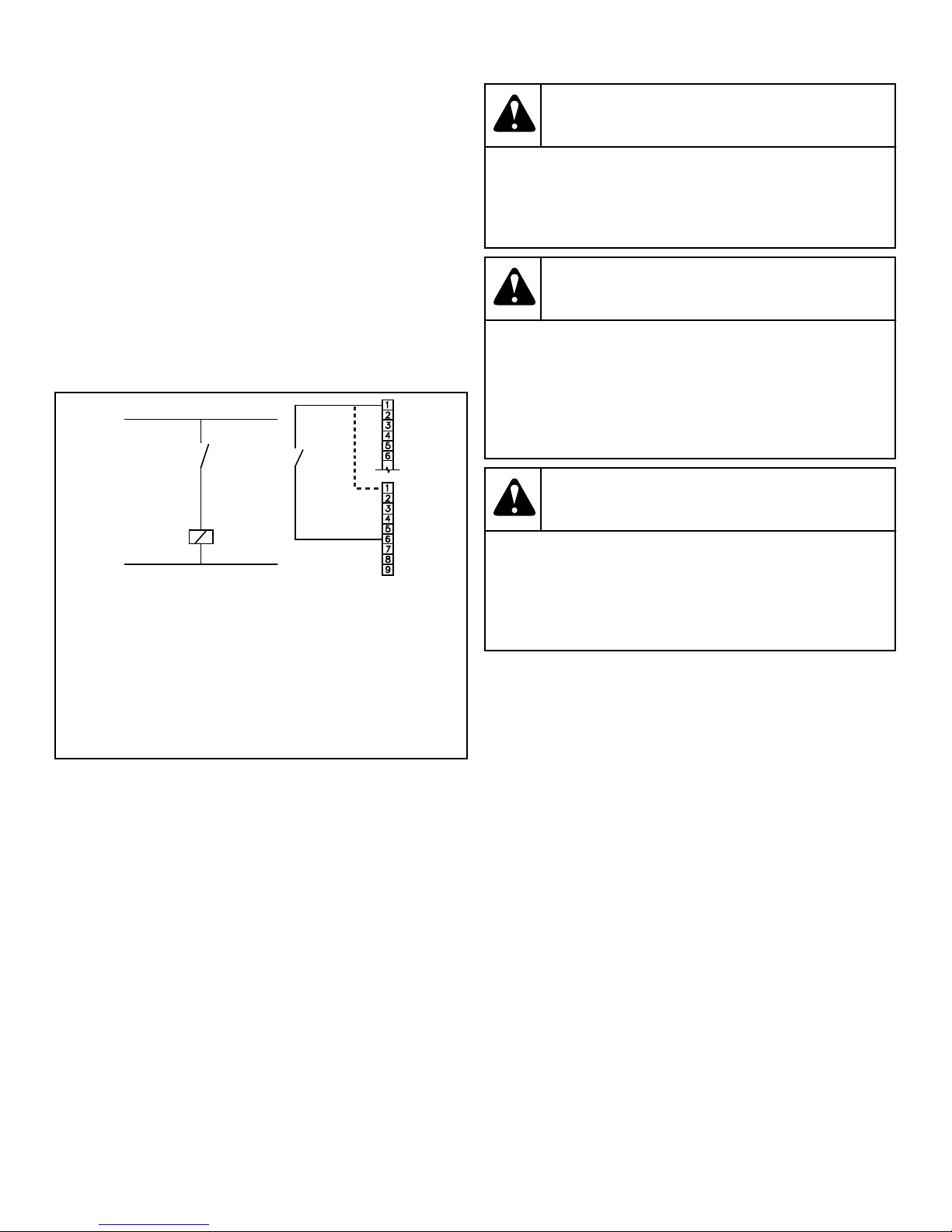
connected to the microprocessor by means of a potential-free
contact. Refer to Figure 18 .
1. L
2. Level switch
3. K1
4. Terminal A
5. Terminal B
6. K1
7. N
Electrical shock hazard will result in death or serious
injury. Disconnect electric power and wait ten (10)
minutes before servicing.
W911
WARNING
Dangerous voltages are present inside the machine.
Only qualified personnel should attempt adjustments
and troubleshooting. Disconnect power from the machine before removing any cover and guards, and
before attempting any service procedures.
W736
WARNING
Hazardous Voltage. Can cause shock, burn or death.
Verify that a ground wire from a proven earth ground
is connected to the lug near the input power block
on this machine.
W360
IMPORTANT: If the machine is not equipped with a
main switch, supply disconnecting devices need to be
provided in the installation for all electrical supplies
connected to the machine, in accordance with EN
60204-1 standard, point 5.3.
Figure 18
The relay contact K1 has to close when the water level is too low.
Terminal B is positioned on the left side, in the lower part of the
microprocessor. Terminal A is positioned directly above Terminal
B. The microprocessor is positioned inside the washer. If the
"Check signal recycle" parameter is set to "yes" in the configuration menu, the timer will send a signal if the water level of the
reuse tank is too low.
Electrical Installation Requirements
IMPORTANT: Electrical ratings are subject to change.
Refer to serial plate for electrical ratings information
specific to your machine.
©
DO NOT COPY or TRANSMIT
Copyright, Alliance Laundry Systems LLC -
IMPORTANT: Make sure the supply voltage is always
within the limits specified. When you have long distances in the electrical installation, it may be necessary to
use bigger cables to reduce the voltage drop.
Models outside of North America:
IMPORTANT: When the machine is connected near a
large capacity power supply transformer (500kVA or
more, wiring length shorter than 32.81 ft [10 m]) or
there is a power capacitor switch-over, a power supply
improving reactor must be installed. If you do not install this, the inverter may get damaged. Contact your
distributor for more information.
Models outside of North America: For electrical protection, if local regulations allow, there must be installed a residual current
device (RCD) and a circuit breaker in the electrical installation of
the building (laundry switchboard). Refer to Figure 19 .
Electrical connections are made at the rear of the machine. The
machine must be connected to the proper electrical supply shown
29 Part No. D1625ENR4
Page 30
CHM2486N_SVG
8
7
6
5
4
3
2
1
Installation
on the serial plate on the rear of the machine, using copper conductors only.
WARNING
Grounding: In event of malfunction, breakdown or
leakage current, grounding will reduce the risk of
electrical shock and serve as a protecting device by
providing a path of least resistance of electrical current. Therefore, it is very important and the responsibility of the installer to assure the washer is adequately grounded at installation, following all national and local requirements.
W902
Residual Current Device (RCD) - Models Outside
of North America
In some countries, an RCD is known as an Earth Leakage Trip,
Ground Fault Circuit Interrupter (GFCI), Appliance Leakage
Current Interrupter (ALCI) or Earth (Ground) Leakage Current
Breaker.
When locally allowed, an RCD must be installed. In some power
network earthing systems, an RCD may not be allowed.
The RCD must have the following specifications:
• Tripping current of 100mA (if not locally available/allowed,
use a 30mA trip current, preferably selective type with small
time delay set)
• Type B (components inside the machine which make use of
DC voltages and require this better performance RCD)
• Maximum of 2 machines installed on each RCD (for 30mA,
only 1 machine)
Some washer control circuits are supplied with a separating transformer. Therefore, the RCD may not detect faults in the control
circuits (but the fuse(s) on the separating transformer will).
Supply Protection Device
A supply protection device protects the machine and wiring
against short circuits. (Glow-wire) fuses or (automatic) circuit
breakers may be used as supply protection devices.
Protection must be the "slow" type, which means curve D for circuit breakers.
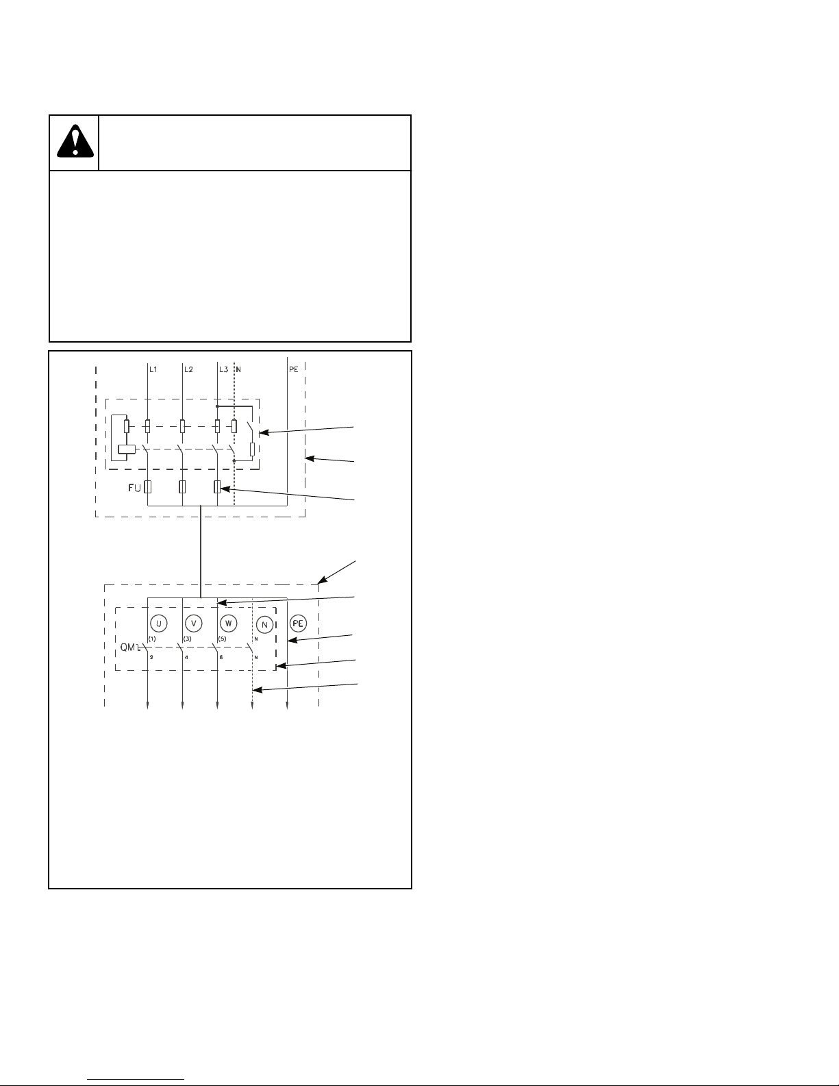
1. Residual current device (RCD)
2. Laundry electrical switchboard
3. Supply protection device
4. Washing machine
5. Phase conductors
6. Protective conductor
7. Main switch inlet terminal switchboard
8. Neutral conductor
Figure 19
IMPORTANT: Alliance Laundry Systems warranty does
not cover components that fail as a result of improper
input voltage.
©
Copyright, Alliance Laundry Systems LLC -
DO NOT COPY or TRANSMIT
30 Part No. D1625ENR4
Page 31
CHM2487N_SVG
7
6
5
4
3
2
1
Installation
Supply Cable
• Stranded conductors (flexible wiring) that can withstand vibration from machine
The supply cable is not delivered with the machine. The supply
cable must have the following specifications:
• Conductors with copper cores (For wire size details, refer to
Electrical Specifications - Models Outside of North America
or Electrical Specifications - North American Models)
• For crossection size, refer to Table 8 Determining AWG Sizes
• Route the supply cable as short as possible, directly from the
supply protection device to the washer without branching off
• Do not use a plug or extensions cords (the machine is intended to be permanently connected to the electrical network)
Min. phase conductor
Power supply protection device nominal current (US)
section, AWG [mm2]
Automatic circuit break-
ers Fuses
16A (15A) 10A (10A) 15 [1.5] 15 [1.5]
20A (20A) 16A (15A) 13 [2.5] 13 [2.5]
25A (-) 20A (20A) 11 [4] 11 [4]
40A (40A) 32A (30A) 9 [6] 9 [6]
63A (-) 50A (50A) 7 [10] 7 [10]
80A 63A 5 [16] 5 [16]
Min. protection conduc-
tor section, AWG [mm2]
100A 80A 3 [25] 5 [16]
125A 100A 2 [35] 3 [25]
Table 8 Determining AWG Sizes
To connect the supply cable, the following steps must be performed:
1. Insert cable through opening on rear panel. Insure a strain relief is used so the supply cable can not move.
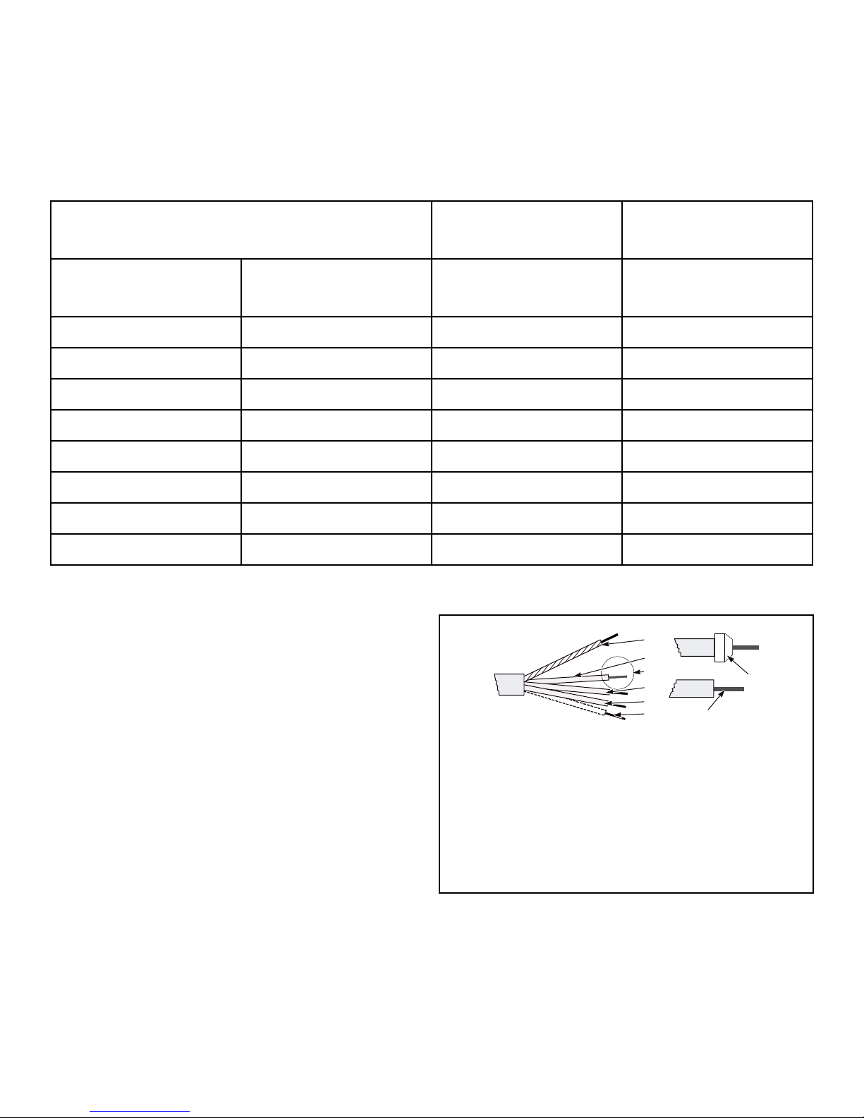
2. Strip the conductor ends. Refer to Figure 20 . The protection
conductor must be longer so it can be routed to the machine
without tension.
1. Protection conductor
2. Phase conductor
3. Phase conductor
4. Phase conductor
5. Neutral conductor
6. Molded tube
7. Stripped length of conductors
Figure 20
©
Copyright, Alliance Laundry Systems LLC -
DO NOT COPY or TRANSMIT
3. With stranded conductors, use wire end tubes with an insulated sleeve (6) for L1/U, (L2/V), (L3/W), (N) conductors.
Make sure there is no accidental contact, since the supply cable stays under voltage even when the main switch is off.
4. Crimp a ring terminal to the protection conductor so it stays
fixed to the PE terminal.
31 Part No. D1625ENR4
Page 32
CHM2488N_SVG
7
6
5
4
3
2
1
CHM2517N_SVG
3
2
1
L1
L2
L3
Installation
5. Connect the supply cable conductors to the incoming terminals (main switch [1]), marked with L1/U, (L2/V), (L3/W),
(N) and the terminal marked with PE. Refer to Figure 21 or
Figure 22 .
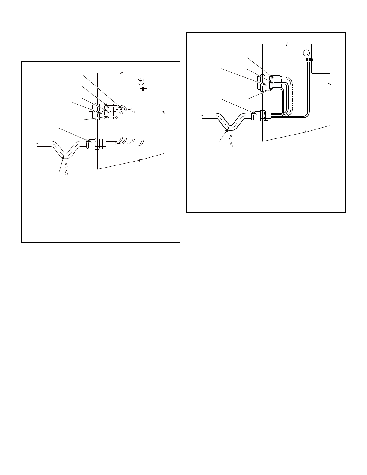
Models outside of North America
1. Main switch
2. Strain relief
3. Sag of inlet cable
4. N
5. W
6. V
7. U
Figure 21
North American Models
1. Main switch
2. Strain relief
3. Sag of inlet cable
4. N
5. L3
6. L2
7. L1
Figure 22
Provide a sag in the cable, in front of the strain relief. This
will prevent condensed water from dripping into the machine.
Refer to Figure 21 or Figure 22 .
©
Copyright, Alliance Laundry Systems LLC -
DO NOT COPY or TRANSMIT
32 Part No. D1625ENR4
Page 33

Machine Protective Earth Connection and Equipotential Bonding
If there are other washers or appliances with exposed conductive
parts, which can touch simultaneously, make sure to make equipotential bonding between all these appliances. The external protective terminal for this purpose is located on the rear panel of the
machine frame. The minimum protection conductor's cross section depends on the supply cable cross section (refer to Table 8
Determining AWG Sizes). However, for the protection purposes,
with the supply cable cross section of a min. 4 mm2, select a larger conductor section, i.e., 6 mm2.
Installation
©
Copyright, Alliance Laundry Systems LLC -
DO NOT COPY or TRANSMIT
33 Part No. D1625ENR4
Page 34
Installation
Input Power Conditioning
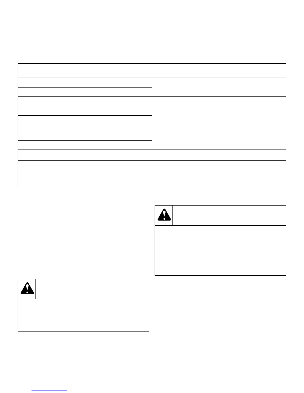
The drive is suitable for direct connection to input power within
the rated voltage of the drive. Listed in Input Power Condition
are certain input power conditions which may cause component
damage or reduction in product life. If any of the conditions exist,
Input Power Condition Possible Corrective Action(s)
Low Line impedance (less than 1% line reactance) • Install Line Reactor
Greater than 120 kVA supply transformer
Line has power factor correction capacitors • Install Line Reactor
Line has frequent power interruptions
Line has intermittent noise spikes in excess of 6000V (lightning)
Phase to ground voltage exceeds 125% of normal line to line
voltage
Ungrounded distribution system
240V open delta configuration (stinger leg)* • Install Line Reactor
* For drives applied on an open delta with a middle phase grounded neutral system, the phase opposite the phase that is tapped in the
middle to the neutral or earth is referred to as the “stinger leg,” “high leg,” “red leg,” etc. This leg should be identified throughout
the system with red or orange tape on the wire at each connection point. The stinger leg should be connected to the center Phase B
on the reactor.
install one of the devices listed under the Possible Corrective Action(s).
IMPORTANT: Only one device per branch circuit is required. It should be mounted closest to the branch and
sized to handle the total current of the branch circuit.
• Isolation Transformer
• Isolation Transformer
• Remove MOV jumper to ground
• Install Isolation Transformer with grounded secondary (if
necessary)
Table 9
Input Voltage Requirements
For voltages above or below listed specifications, contact your
power company or local electrician.
If machine is intended for four-wire service, a neutral leg must be
provided by power company.
If a delta supply system is used on a four-wire model, connect
high leg to L3.
IMPORTANT: Improper connections will result in equipment damage and will void warranty.
DANGER
Electrical shock hazard will result in death or serious
injury. Disconnect electric power and wait five (5) minutes before servicing.
W810
DANGER
Hazardous Rotation Speed. Will cause serious injury
when controlling AC inverter drive with a parameter
unit, safety features are bypassed allowing basket to
rotate at high speeds with the door open. Place large
sign on front of machine to warn people of imminent
danger.
W361
Circuit Breakers and Quick Disconnects
Single-phase machines require a single-phase inverse-time circuit
breaker. Three-phase machines require a separate, three-phase inverse-time circuit breaker to prevent damage to the motor by disconnecting all legs if one should be lost accidentally. Refer to
section for model-specific circuit breaker requirements.
IMPORTANT: All quick disconnects should comply with
the specifications. DO NOT use fuses instead of circuit
breakers.
©
Copyright, Alliance Laundry Systems LLC -
DO NOT COPY or TRANSMIT
34 Part No. D1625ENR4
Page 35
N
CHM2499N_SVG
Installation
Connection Specifications
IMPORTANT: Connection must be made by a qualified
electrician using wiring diagram provided with machine, or according to accepted European Union standards.
Connect machine to an individual branch circuit not shared with
lighting or other equipment. Shield connection in a liquid-tight or
approved flexible conduit. Copper conductors of correct size
must be installed in accordance with National Electric Code
(NEC) or other applicable codes.
Use wire sizes indicated in the Electrical Specifications chart for
runs up to 50 feet [15 m]. Use next larger size for runs of 50 to
100 feet [15 to 30 m]. Use two (2) sizes larger for runs greater
than 100 feet [30 m].
Single-Phase Connections
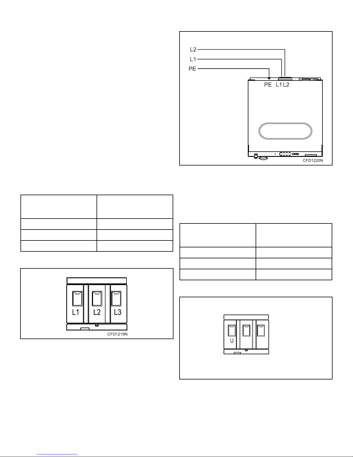
Single Phase Connection - North American Models
Connect the electrical service's wires to the machine's electrical
connection terminal as shown.
Machine's Electrical
Electrical Service Wire
L1 L1
L2 L2
PE PE (Ground)
Table 10
Connection Terminal
North American Models with Single-Phase Connection
Figure 24
Single Phase Connection - Models outside of North
America
Connect the electrical service's wires to the machine's electrical
connection terminal as shown.
Machine's Electrical
Electrical Service Wire
U U
Neutral N
Connection Terminal
Electrical Connection Terminal Block
Figure 23
©
Copyright, Alliance Laundry Systems LLC -
DO NOT COPY or TRANSMIT
PE PE (Ground)
Table 11
Electrical Connection Terminal Block
Figure 25
35 Part No. D1625ENR4
Page 36
PE U N
PE
N
U
CHM2500N_SVG
V W N
CHM2501N_SVG
Installation
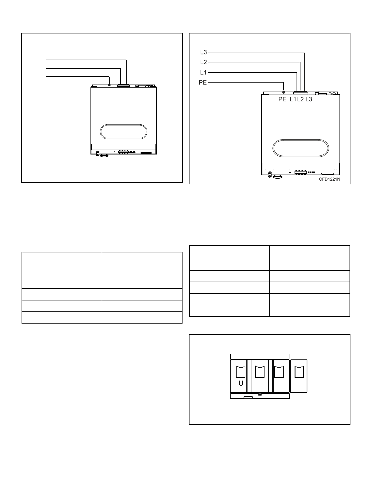
Models outside of North America with Single-Phase
Connection
Figure 26
Three-Phase Connections
Three Phase Connection - North American Models
Connect the electrical service's wires to the machine's electrical
connection terminal as shown.
Machine's Electrical
Electrical Service Wire
L1 L1
L2 L2
L3 L3
PE PE (Ground)
Table 12
Connection Terminal
North American Models with Three-Phase Connection
Figure 27
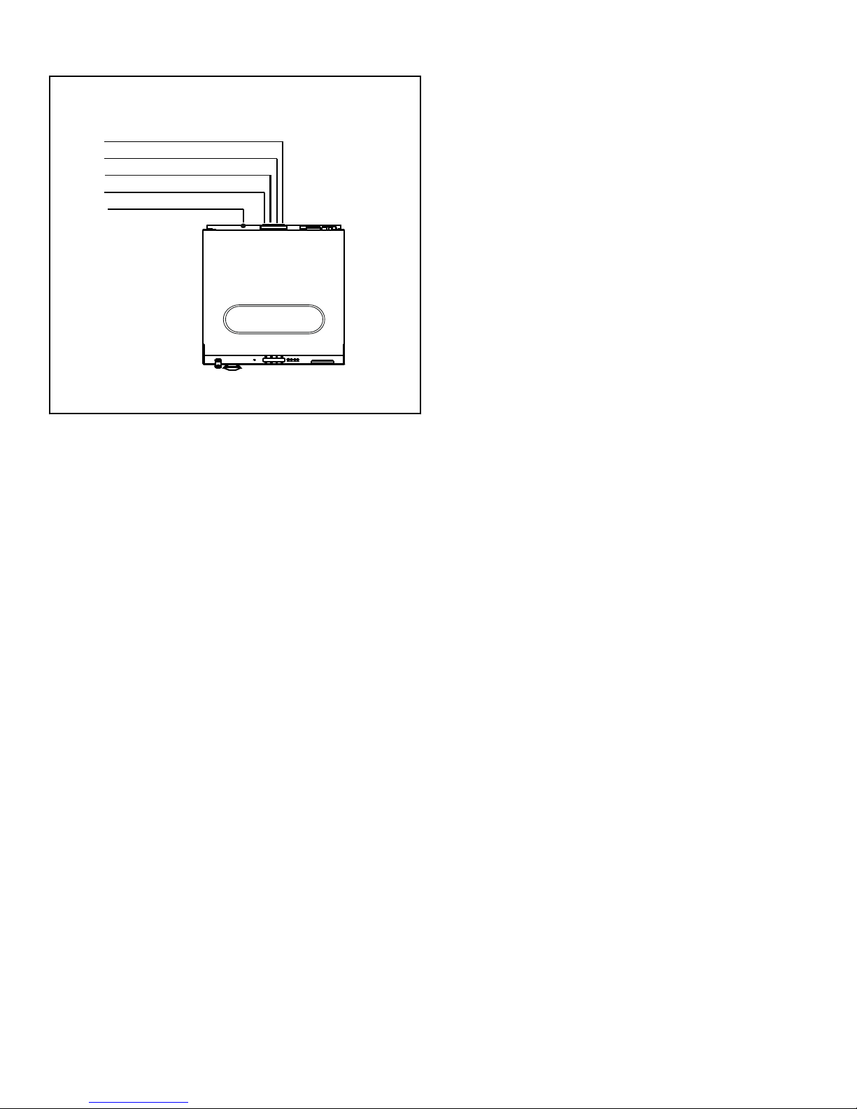
Three Phase Connection - Models Outside of North
America
Connect the electrical service's wires to the machine's electrical
connection terminal as shown.
Machine's Electrical
Electrical Service Wire
U U
V V
W W
PE PE (Ground)
Table 13
Electrical Connection Terminal Block
Connection Terminal
©
Copyright, Alliance Laundry Systems LLC -
DO NOT COPY or TRANSMIT
Figure 28
36 Part No. D1625ENR4
Page 37
Models Outside of North America with Three-Phase
U
V
PE UV
W
WPEN
N
CHM2502N_SVG
Connection
Figure 29
Installation
Phase Adder
Machines can be converted for lower voltage operation and/or 50
Hz operation. Refer to conversion label by serial plate for details.
IMPORTANT: Do not use a phase adder on any machine.
Thermal Overload Protector
For models with inverter drives, the inverter drive provides overload protection for the drive motor.
©
Copyright, Alliance Laundry Systems LLC -
DO NOT COPY or TRANSMIT
37 Part No. D1625ENR4
Page 38
Installation
Electrical Specifications - Models Outside of North America
7 kg / 14 lb. / 65 L Models
Hot and
Cold Water
Inlet
Valves
Full Load
Amps
Voltage Cycle Phase Wire
Total
power
(kW)
Electric
Heat
Full Load
Amps
(Electric
Heating
kW) Fuse (A)
200-240 50-60 1 2 (L1, L2, or
0.85 6.6 N/A 10
L1, N)
200-240 50-60 1 2 (L1, L2 or
3.6 N/A 17.9 (3) 20
L1, N)
200-240 50-60 1 2 (L1, L2, or
5.2 N/A 24.9 (4.6) 32
L1, N)
200-240 50-60 3 3 (L1, L2, L3) 6.7 N/A 20 (6) 25
200-240 50-60 3 3 (L1, L2, L3) 9.7 N/A 27.5 (9) 32
380-415 + N 50-60 3 4 (L1, L2, L3,N)6.7 N/A 13.5 (6) 16
380-415 + N 50-60 3 4 (L1, L2, L3,N)9.7 N/A 18 (9) 20
380-415 50-60 3 3 (L1, L2, L3) 0.85 2.4 N/A 10
440-480 50-60 3 3 (L1, L2, L3) 0.85 2.4 N/A 10
380-415 50-60 3 3 (L1, L2, L3) 6.7 N/A 9.9 (6) 16
380-415 50-60 3 3 (L1, L2, L3) 9.7 N/A 15.3 (9) 20
440-480 50-60 3 3 (L1, L2, L3) 9.7 N/A 13.8 (9) 16
©
Copyright, Alliance Laundry Systems LLC -
DO NOT COPY or TRANSMIT
Table 14
38 Part No. D1625ENR4
Page 39
8 kg / 20 lb. / 80 L Models
Voltage Cycle Phase Wire
Total
power
(kW)
Hot and
Cold Water
Inlet
Valves
Full Load
Amps
Installation
Electric
Heat
Full Load
Amps
(Electric
Heating
kW) Fuse (A)
200-240 50-60 1 2 (L1, L2, or
0.85 6.7 N/A 10
L1, N)
200-240 50-60 1 2 (L1, L2 or
3.6 N/A 18 (3) 20
L1, N)
200-240 50-60 1 2 (L1, L2, or
5.2 N/A 25.1 (4.6) 32
L1, N)
200-240 50-60 3 3 (L1, L2, L3) 6.7 N/A 20.2 (6) 25
200-240 50-60 3 3 (L1, L2, L3) 9.7 N/A 27.9 (9) 32
380-415 + N 50-60 3 4 (L1, L2, L3,N)6.7 N/A 13.7 (6) 16
380-415 + N 50-60 3 4 (L1, L2, L3,N)9.7 N/A 18.2 (9) 20
380-415 50-60 3 3 (L1, L2, L3) 0.85 2.5 N/A 10
440-480 50-60 3 3 (L1, L2, L3) 0.85 2.5 N/A 10
380-415 50-60 3 3 (L1, L2, L3) 6.7 N/A 10 (6) 16
380-415 50-60 3 3 (L1, L2, L3) 9.7 N/A 15.4 (9) 20
440-480 50-60 3 3 (L1, L2, L3) 9.7 N/A 13.9 (9) 16
©
Copyright, Alliance Laundry Systems LLC -
DO NOT COPY or TRANSMIT
Table 15
39 Part No. D1625ENR4
Page 40
Installation
11 kg / 25 lb. / 105 L Models
Voltage Cycle Phase Wire
Total
power
(kW)
Hot and
Cold Water
Inlet
Valves
Full Load
Amps
Electric
Heat
Full Load
Amps
(Electric
Heating
kW) Fuse (A)
200-240 50-60 1 2 (L1, L2, or
1.2 9.8 N/A 16
L1, N)
200-240 50-60 1 2 (L1, L2 or
3.8 N/A 18.5 (3) 25
L1, N)
200-240 50-60 1 2 (L1, L2, or
5.4 N/A 25.5 (4.6) 32
L1, N)
200-240 50-60 3 3 (L1, L2, L3) 6.8 N/A 20.5 (6) 25
200-240 50-60 3 3 (L1, L2, L3) 9.8 N/A 28.1 (9) 32
200-240 50-60 3 3 (L1, L2, L3) 12.8 N/A 35.6 (12) 40
380-415 + N 50-60 3 4 (L1, L2, L3,N)6.8 N/A 14.1 (6) 16
380-415 + N 50-60 3 4 (L1, L2, L3,N)9.8 N/A 18.5 (9) 20
380-415 + N 50-60 3 4 (L1, L2, L3,N)12.8 N/A 22.8 (12) 25
380-415 50-60 3 3 (L1, L2, L3) 1.2 3.2 N/A 10
440-480 50-60 3 3 (L1, L2, L3) 1.2 3.2 N/A 10
380-415 50-60 3 3 (L1, L2, L3) 6.8 N/A 10.1 (6) 16
380-415 50-60 3 3 (L1, L2, L3) 9.8 N/A 15.5 (9) 16
440-480 50-60 3 3 (L1, L2, L3) 9.8 N/A 14 (9) 16
380-415 50-60 3 3 (L1, L2, L3) 12.8 N/A 19.9 (12) 25
440-480 50-60 3 3 (L1, L2, L3) 12.8 N/A 18.2 (12) 25
©
Copyright, Alliance Laundry Systems LLC -
DO NOT COPY or TRANSMIT
Table 16
40 Part No. D1625ENR4
Page 41
14 kg / 30 lb. / 135 L Models
Voltage Cycle Phase Wire
Total
power
(kW)
Hot and
Cold Water
Inlet
Valves
Full Load
Amps
Installation
Electric
Heat
Full Load
Amps
(Electric
Heating
kW) Fuse (A)
200-240 50-60 1 2 (L1, L2, or
1.6 10.1 N/A 16
L1, N)
200-240 50-60 1 2 (L1, L2, or
5.7 N/A 27 (4.6) 32
L1, N)
200-240 50-60 3 3 (L1, L2, L3) 10.1 N/A 29.6 (9) 32
200-240 50-60 3 3 (L1, L2, L3) 13.1 N/A 37.2 (12) 40
380-415 + N 50-60 3 4 (L1, L2, L3,N)10.1 N/A 18 (9) 20
380-415 + N 50-60 3 4 (L1, L2, L3,N)13.1 N/A 22.6 (12) 25
380-415 50-60 3 3 (L1, L2, L3) 1.6 3.6 N/A 10
440-480 50-60 3 3 (L1, L2, L3) 1.6 3.6 N/A 10
380-415 50-60 3 3 (L1, L2, L3) 10.1 N/A 16 (9) 20
440-480 50-60 3 3 (L1, L2, L3) 10.1 N/A 14.8 (9) 16
380-415 50-60 3 3 (L1, L2, L3) 13.1 N/A 19.9 (12) 20
440-480 50-60 3 3 (L1, L2, L3) 13.1 N/A 18.7 (12) 25
©
Copyright, Alliance Laundry Systems LLC -
DO NOT COPY or TRANSMIT
Table 17
41 Part No. D1625ENR4
Page 42
Installation
18 kg / 40 lb. / 180 L Models
Voltage Cycle Phase Wire
Total
power
(kW)
Hot and
Cold Water
Inlet
Valves
Full Load
Amps
Electric
Heat
Full Load
Amps
(Electric
Heating
kW) Fuse (A)
200-240 50-60 1 2 (L1, L2, or
2.3 14.2 N/A 20
L1, N)
200-240 50-60 3 3 (L1, L2, L3) 13.5 N/A 37.9 (12) 40
200-240 50-60 3 3 (L1, L2, L3) 19.5 N/A 53.3 (18) 63
380-415 + N 50-60 3 4 (L1, L2, L3,N)13.5 N/A 23.1 (12) 25
380-415 + N 50-60 3 4 (L1, L2, L3,N)19.5 N/A 31.9 (18) 32
380-415 50-60 3 3 (L1, L2, L3) 2.3 5.2 N/A 10
440-480 50-60 3 3 (L1, L2, L3) 2.3 5.2 N/A 10
380-415 50-60 3 3 (L1, L2, L3) 13.5 N/A 20.9 (12) 25
440-480 50-60 3 3 (L1, L2, L3) 13.5 N/A 19.7 (12) 25
380-415 50-60 3 3 (L1, L2, L3) 19.5 N/A 30.5 (18) 32
440-480 50-60 3 3 (L1, L2, L3) 19.5 N/A 27.2 (18) 32
Table 18
©
Copyright, Alliance Laundry Systems LLC -
DO NOT COPY or TRANSMIT
42 Part No. D1625ENR4
Page 43
24 kg / 55 lb. / 240 L Models
Voltage Cycle Phase Wire
Total
power
(kW)
Hot and
Cold Water
Inlet
Valves
Full Load
Amps
Installation
Electric
Heat
Full Load
Amps
(Electric
Heating
kW) Fuse (A)
200-240 50-60 1 2 (L1, L2, or
3.1 15 N/A 20
L1, N)
200-240 50-60 3 3 (L1, L2, L3) 20 N/A 54.3 (18) 63
380-415 + N 50-60 3 4 (L1, L2, L3,N)20 N/A 31.9 (18) 32
380-415 50-60 3 3 (L1, L2, L3) 3.1 7.1 N/A 10
440-480 50-60 3 3 (L1, L2, L3) 3.1 7.1 N/A 10
380-415 50-60 3 3 (L1, L2, L3) 20 N/A 31.5 (18) 32
440-480 50-60 3 3 (L1, L2, L3) 20 N/A 28.2 (18) 32
Table 19
©
Copyright, Alliance Laundry Systems LLC -
DO NOT COPY or TRANSMIT
43 Part No. D1625ENR4
Page 44
Installation
28 kg / 70 lb. / 280 L Models
Voltage Cycle Phase Wire
Total
power
(kW)
Hot and
Cold Water
Inlet
Valves
Full Load
Amps
Electric
Heat
Full Load
Amps
(Electric
Heating
kW) Fuse (A)
200-240 50-60 1 2 (L1, L2, or
3.1 16 N/A 20
L1, N)
200-240 50-60 3 3 (L1, L2, L3) 23.9 N/A 64 (21.9) 80
380-415 + N 50-60 3 4 (L1, L2, L3,N)23.9 N/A 40.5 (21.9) 50
380-415 50-60 3 3 (L1, L2, L3) 3.1 7.2 N/A 10
440-480 50-60 3 3 (L1, L2, L3) 3.1 7.2 N/A 10
380-415 50-60 3 3 (L1, L2, L3) 23.9 N/A 37 (21.9) 40
440-480 50-60 3 3 (L1, L2, L3) 23.9 N/A 34 (21.9) 40
Table 20
Electrical Specifications - North American Models
8 kg / 20 lb. / 80 L Models
Circuit
Code Voltage Cycle Phase Wire
Full Load
Amps
Breaker
CSA
AWG
(mm2)
X 200-240 60 1/3 2 (L1, L2 or
©
Copyright, Alliance Laundry Systems LLC -
DO NOT COPY or TRANSMIT
6.7 10 14 (2.5)
L1, N)
Table 21
44 Part No. D1625ENR4
Page 45
11 kg / 25 lb. / 105 L Models
Code Voltage Cycle Phase Wire
Full Load
Amps
Circuit
Breaker
CSA
Installation
AWG
(mm2)
X 200-240 60 1/3 2 (L1, L2 or
L1, N)
Table 22
14 kg / 30 lb. / 135 L Models
Code Voltage Cycle Phase Wire
X 200-240 60 1/3 2 (L1, L2 or
L1, N)
Table 23
18 kg / 40 lb. / 180 L Models
Code Voltage Cycle Phase Wire
X 200-240 60 1/3 2 (L1, L2 or
L1, N)
9.8 15 14 (2.5)
Circuit
Full Load
Amps
Breaker
CSA
AWG
(mm2)
10.1 15 14 (2.5)
Circuit
Full Load
Amps
Breaker
CSA
AWG
(mm2)
14.2 20 12 (4)
Table 24
24 kg / 55 lb. / 240 L Models
Code Voltage Cycle Phase Wire
X 200-240 60 1/3 2 (L1, L2 or
L1, N)
N 440-480 60 3 3 (L1, L2,
L3)
Table 25
Circuit
Full Load
Amps
Breaker
CSA
AWG
(mm2)
15 20 12 (4)
7.1 10 14 (2.5)
©
Copyright, Alliance Laundry Systems LLC -
DO NOT COPY or TRANSMIT
45 Part No. D1625ENR4
Page 46
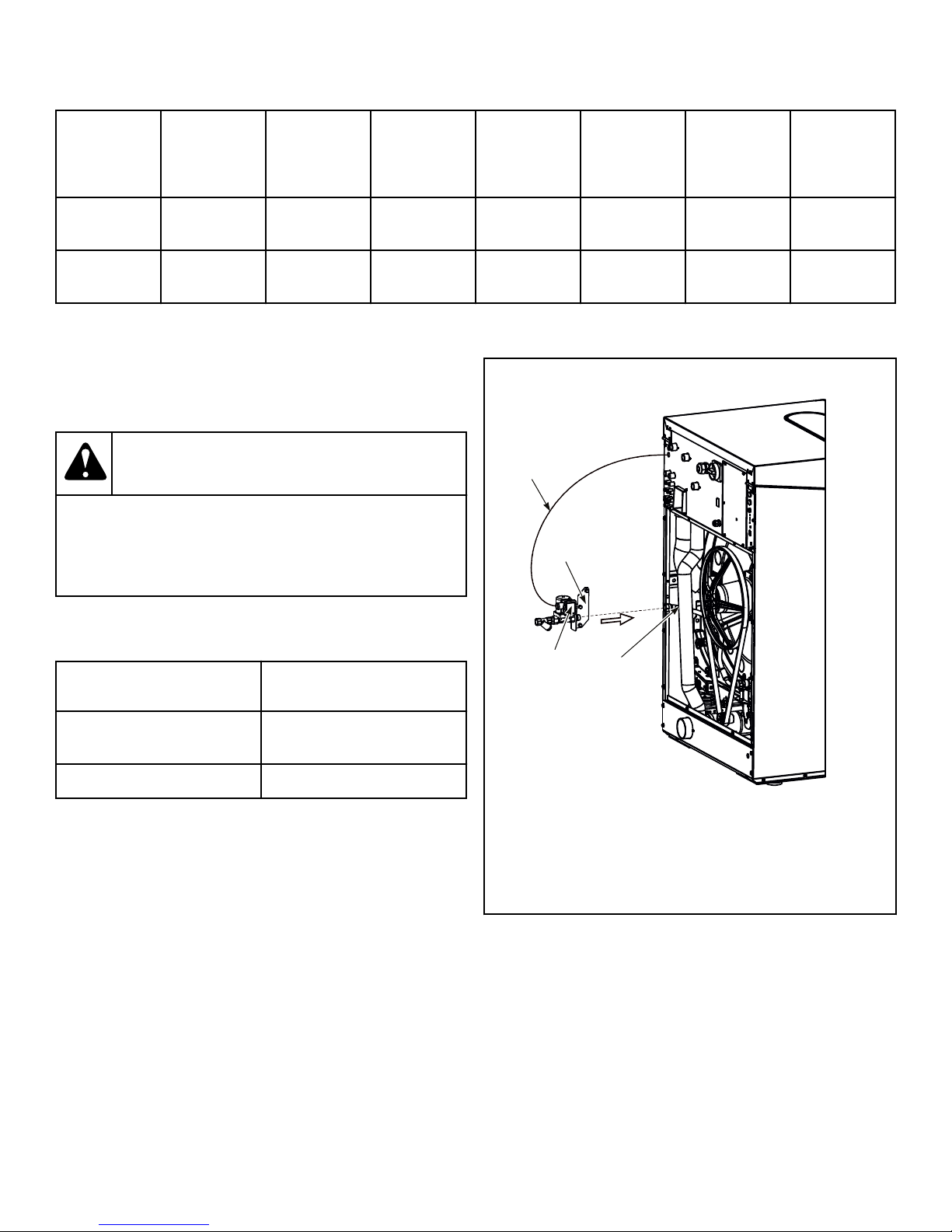
CHM2483N_SVG
4
3
2
1
Installation
28 kg / 70 lb. / 280 L Models
Code Voltage Cycle Phase Wire
Full Load
Amps
Circuit
Breaker
CSA
AWG
(mm2)
X 200-240 60 1/3 2 (L1, L2 or
L1, N)
N 440-480 60 3 3 (L1, L2,
L3)
Table 26
Steam Requirements (Steam Heat Op-
tion Only)
WARNING
Hot Surfaces. Will cause severe burns. Turn steam
off and allow steam pipes, connections and components to cool before touching.
W505
For machines equipped with optional steam heat, install piping in
accordance with approved commercial steam practices. Steam requirements are shown in Table 27 .
16 20 14 (2.5)
7.2 10 14 (2.5)
Specification Requirement
Steam inlet connection size,
in. BSP
Steam pressure, PSI [bar] 15-116 [1-8]
IMPORTANT: It is necessary to insert a filter with permeability up to 0.0118 in. [300 µm] in front of the steam
valve. Dirt larger than 0.0118 in. [300 µm] may damage
the steam valve and cause leaks.
IMPORTANT: Failure to install the customer supplied
steam filter may void the warranty.
Use an inlet steam pressure hose only adapted to the steam valve
with appropriate seal suitable for the applied working pressure.
Steam Valve Installation
1. Remove the rear cover.
2. Fit the bracket with the steam valve and filter onto the rear
part of machine.
1/2"
Table 27
1. Bracket
2. Steam hose
3. Cable
4. Steam coil
Figure 30
3. Connect steam hose to steam valve.
4. Connect the cable to the steam coil.
5. Fit rear cover back to its original place.
©
Copyright, Alliance Laundry Systems LLC -
DO NOT COPY or TRANSMIT
46 Part No. D1625ENR4
Page 47
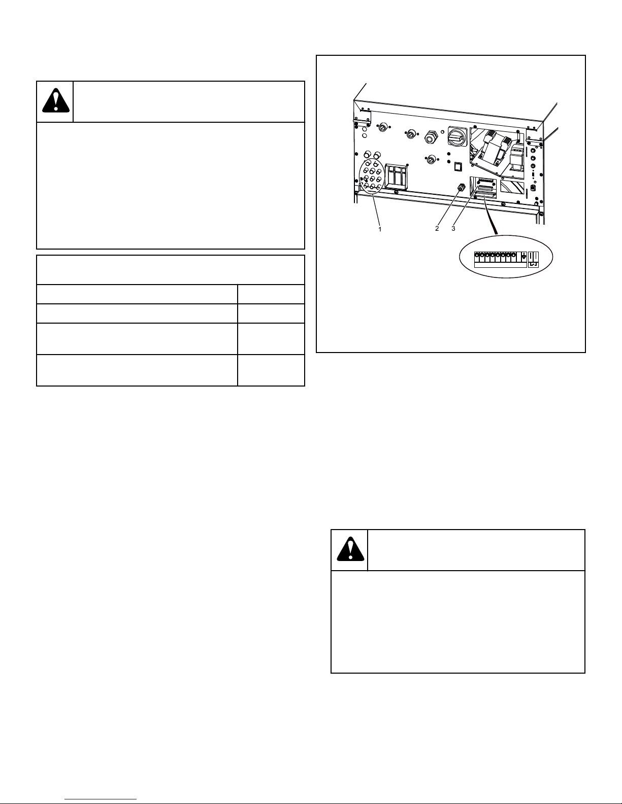
Electrical connection label
8
H804 524740
1 7
6253
4
24V AC
(MAX 10mA/supply)
CFD3112N
Installation
Supply Dispensing
WARNING
Dangerous Chemicals. May damage eyes and skin.
Wear eye and hand protection when handling chemicals; always avoid direct contact with raw chemicals.
Read the manufacturer’s directions for accidental
contact before handling chemicals. Ensure an eyerinse facility and an emergency shower are within
easy reach. Check at regular intervals for chemical
leaks.
Supply Dispensing
Number of external liquid supply connections 8
Liquid supply connection size, in. [mm] 5/16 [8]
Number of diluted liquid soap supply connections
3
Valve Panel-Rear View
W363
1. External Supply Hose Connections
2. Cable Bushing
3. Control Signals Terminal Box
Diluted liquid soap supply connection size, in.
1/2 [12]
[mm]
Table 28
IMPORTANT: Always use liquid soap pumps with a
flow that bring the requested quantity in less than 30
sec.
IMPORTANT: Start pumping immediately after water
valves are open. The incoming water dilutes the liquid
soap and brings it into the tub assembly.
Secure the location of the wiring and hoses so they can not be
pinched, damaged or rubbed. Before you start to use liquid soap,
check with your liquid soap supplier whether the liquid soap is
harmless and inert to PP and PVC material in order to avoid damage to machine.
IMPORTANT: Failure to follow these instructions could
damage the machine and void the warranty.
Connection of External Liquid Supplies
1. Facing the rear of the machine, locate the eight (8) 5/16 inch
[8 mm] supply hose connections found on the left-hand side
of the valve panel. Refer to Figure 31 .
Figure 31
2. Drill through the eight (8) plastic holes on the valve panel for
the external supply hoses as needed.
NOTE: On the valve panel by the external supply
hose connections are three (3) connections of 1/2
in. 12 mm that are to be used only for entering diluted soap. To use, drill a 7/16 inch 11.5 mm hole only
in connections that will be used.
3. Remove plastic debris.
4. Attach the external supply hoses to the ports at each of the
drilled holes.
5. Secure with proper clamps.
WARNING
Check that the hose connections are tight (check
the clamps). Any chemical leakage may cause serious bodily injuries as well as serious damage to
the washer. If one of the connections is open,
close and secure the opening with an appropriate
cover.
W909
©
Copyright, Alliance Laundry Systems LLC -
DO NOT COPY or TRANSMIT
NOTE: Do not attempt to make chemical injection supply pump electrical connections to points other than
those provided specifically for that purpose by the factory.
47 Part No. D1625ENR4
Page 48
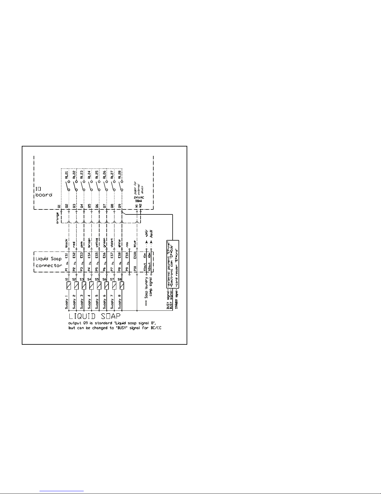
CFD3113N
Installation
Electrical Connection of External Liq-
uid Soap Supply System
The power supply of the external liquid soap supply syste has to
be connected to an external electrical source. Only authorized
workers with valid qualifications must execute the electrical connection on the machine according to valid local standards. The
correction connection can be found on the wiring diagram included with the machine. Do not connect the liquid soap pump system in the washer.
The electric connection for supply control signals is available on
the rear panel. Refer to Figure 31 . At the terminal box, there is a
label for electric connection. Detail on connection of signals can
also be found on the electric scheme of the machine.
Figure 32
Signals for supply pump control are 24 VAC. Maximum current
for control circuits of pump must be limited to 100mA. Lead the
cable for connetion of pump control signals through the plastic
cable bushing. After connection of conductors to the respective
positions of the connector "P", fix up the cable by tightening the
cable bushing against disconnections and close the box with the
cover. For details about liquid soap supply sytem programming,
refer to Programming Manual.
©
Copyright, Alliance Laundry Systems LLC -
DO NOT COPY or TRANSMIT
48 Part No. D1625ENR4
Page 49
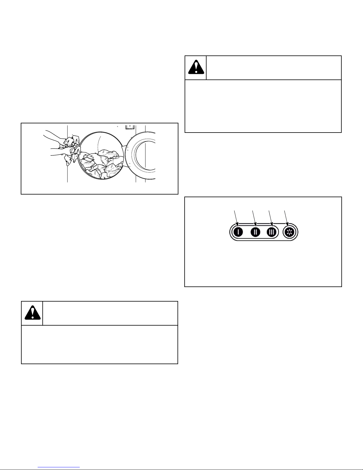
Operation
U003I_SVG
CHM2462N_SVG
1 2
3
4
Operating Instructions
1. Turn on main power source (circuit breaker).
2. Pull on the door handle to open the door.
3. Load to capacity whenever possible. DO NOT OVERLOAD.
Refer to Figure 33 .
NOTE: Underloading can cause out-of-balance conditions that can shorten machine life.
Operation
WARNING
Water cannot be extracted from rubber backed
items. To avoid damage to machine from out of balance conditions, do not use a spin (extract) step
when washing rubber backed items. Warranty will be
voided.
W880
6. Add liquid supplies to supply dispenser and close lid.
NOTE: It is advisable to use only detergents with
"softener to break the suds", which can easily be
found in retail shops. Do not use gel detergents.
The dosage of soap is generally mentioned on the
packing. An overdose of detergent can lead to poor
wash results and suds or overflow which can damage the machine.
Figure 33
4. Close the door by applying moderate pressure on the door
handle and simultaneously turning door handle partially to the
left.
NOTE: Make sure the door is closed properly before
operating washing machine. Do not turn the handle
completely around or the safety system will not engage. The safety system serves as protection
against violent handling and damage to the door
lock while the machine is operating.
5. Choose the desired wash program best corresponding to the
quality of the garments and allowed wash temperature in the
wash load.
WARNING
To prevent personal injury, avoid contact with inlet
water temperatures higher than 125° Fahrenheit [51°
Celsius] and hot surfaces.
W748
1. Detergent for the pre-wash
2. Detergent for the main wash
3. Liquid detergent for the main wash or liquid bleach, etc.
4. Liquid fabric softener or liquid starch for the last rinse
Figure 34
7. For vended models only, insert coin(s) or card as necessary.
• If the machine is a coin operated unit, add coins. As each
coin is added, the vend counts down to the amount remaining.
8. Press the START keypad.
9. During first 150 seconds, the desired wash cycle can be
changed. After first 150 seconds have ended, the wash cycle
active at that moment remains the chosen wash cycle.
10. The wash cycle time is counted down to zero on the display.
After completion, the door lock unlocks and the display
shows “UNLOAD”.
©
Copyright, Alliance Laundry Systems LLC -
DO NOT COPY or TRANSMIT
49 Part No. D1625ENR4
Page 50
Operation
WARNING
If, after a power disconnect, the machine door
cannot be opened and the machine is fitted with
an automatic unlocking circuit, wait until the locking circuit unlocks the door lock. Before you open
the door, make sure that the drum is completely
still and all water has drained.
Power Cut
If a power cut occurs in an idle conditon of the machine and no
wash program is running, the machine remains in the idle condition.
Aries Control Models
If a power cut occurs during the wash process and the door remains closed and locked, the wash program will, after the power
supply has been restored, automatically continue in the program
beginning from the step in which the program was interrupted.
For machines fitted with an automatic door-lock unlocking module, refer to Automatic Door-lock Unlocking Module section. If
during the power cut, the door lock gets unlocked and the door
remains closed, the message "PRESS START / OPEN DOOR"
appears as soon as the power supply is restored. If you open the
door, the wash program will be cancelled. If you press the
START button, the wash program will continue beginning from
the step in which the program was interrupted.
WARNING
The automatic door-lock unlocking module must not
be utilized on machines that are fitted with a drain
pump or reverse function drain valve.
W910
W903
Aries Elite Control Models
If a power cut occurs during the wash process, the message
"CONTINUE / STOP" appears as soon as the power supply is restored. If you press the STOP button, the wash program will be
cancelled. If you press the START button, the wash program will
continue beginning from the step in which the program was interrupted.
Automatic Door-lock Unlocking Module
Some machines are fitted with an automatic module for unlocking the door lock in case of a power cut.
If a short term power cut occurs, this module does not affect the
operation of the machine.
If a long term power cut occurs, the module unlocks the door
lock. It is then possible to open the door and remove laundry.
©
Copyright, Alliance Laundry Systems LLC -
DO NOT COPY or TRANSMIT
50 Part No. D1625ENR4
Page 51
Maintenance
Maintenance
Maintenance
WARNING
Use the proper chemical agents which avoid calcium
sediments on heating elements and other machine
parts. Discuss the issue with your supplier of washing products. The manufacturer of the machine is
not responsible for the damage of heating elements
and other machine parts due to calcium sediments.
W904
WARNING
Sharp edges can cause personal injury. Wear safety
glasses and gloves, use proper tools and provide
lighting when handling sheet metal parts.
W366R1
IMPORTANT: Replace all panels that are removed to
perform service and maintenance procedures. Do not
operate the machine with missing guards or with broken or missing parts. Do not bypass any safety devices.
Daily
IMPORTANT: Replace all panels that are removed to
perform maintenance procedures. Do not operate the
machine with missing guards or with broken or missing parts. Do not bypass any safety devices.
WARNING
Do not spray the machine with water. Short circuiting
and serious damage may result.
W782
IMPORTANT: Door lock should be checked daily to ensure proper operation. Also check that all safety and
instruction stickers are on the machine. Any missing or
illegible safety instructions stickers should be replaced
immediately.
a. Attempt to start the machine with the door open. The ma-
chine should not start.
b. Close the door without locking it and start the machine.
The machine should not start.
c. Attempt to open the door while the cycle is in progress.
The door should not open.
If the door lock and interlock are not functioning properly, disconnect power and call a service technician.
2. Check the machine for leaks.
a. Start an unloaded cycle to fill the machine.
b. Verify that door and door gasket do not leak.
c. Verify that the drain valve is operating and that the drain
system is free from obstruction. If water does not leak out
during the first wash segment, the drain valve is closed
and functioning properly.
3. Inspect water inlet valve hose connections on the back of the
machine for leaks.
4. Inspect steam hose connections for leaks (if applicable).
5. On machines equipped with an automatic Chemical Supply
System, check all the hoses and hose connections for leaks or
visible signs of deterioration. Replace immediately if either
are present. Chemical leaks can cause damage to the machine’s components.
WARNING
To reduce the risk of electrical shock, serious injury or death, disconnect the electrical power to
washer-extractor before examining the wiring.
W636
6. Verify that insulation is intact on all external wires and that all
connections are secure. If bare wire is evident, call a service
technician.
7. Ensure all panels and guards are properly installed.
End of Day
1. Inspect and clean the basket and door gasket of residual detergent and all foreign matter.
2. Clean the door glass and between the door gasket and the
door with a damp cloth.
3. Clean supply dispenser lid and general area with mild detergent. Flush the dispenser with clean water.
4. Clean the machine’s top, front and side panels with all-purpose cleaner. Rinse with clean water and dry.
Beginning of Day
1. Check door interlock before starting operation:
©
Copyright, Alliance Laundry Systems LLC -
DO NOT COPY or TRANSMIT
51 Part No. D1625ENR4
Page 52
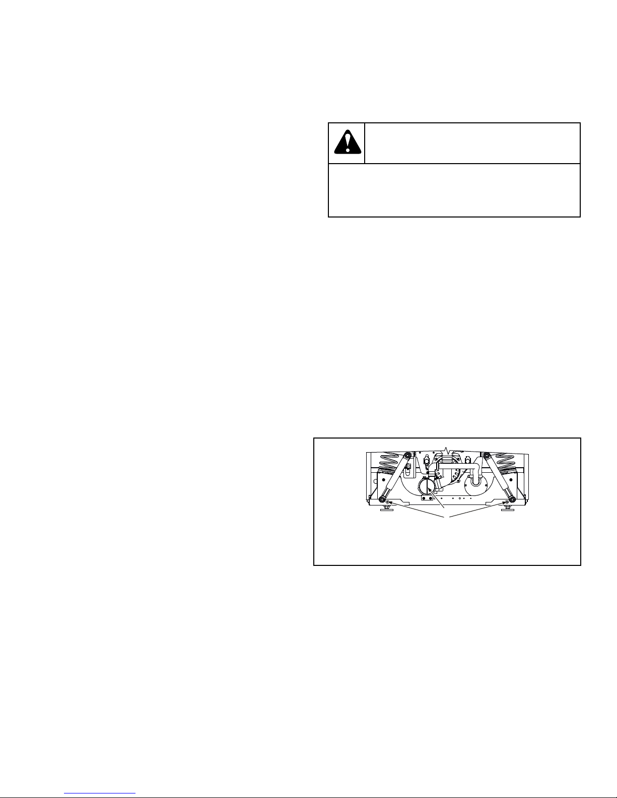
CHM2489N_SVG
2
1
Maintenance
IMPORTANT: Use only isopropyl alcohol to clean
graphic overlays. Never use ammonia-based, vinegar- based or acetone-based cleaners on graphic
overlays.
NOTE: Unload the machine promptly after each
completed cycle to prevent moisture buildup. Leave
loading door and dispenser lid open at the end of
each completed cycle to allow moisture to evaporate.
5. Leave the loading door open at the end of each day to allow
moisture to evaporate.
6. Shut off water supply.
Quarterly
NOTE: Disconnect power to the machine at its source
before performing the quarterly maintenance procedures.
1. Check the bearing house for leakage.
2. Verify that the drain valve is operating and that the drain sys-
tem is free from obstruction. If water does not leak out during
the first wash segment, the drain valve is closed and functioning properly.
3. Visually check all hoses and connections inside machine for
leaks.
4. Make sure that control components are protected against
moisture and dust during the clean up. Wipe and clean the
machine inside.
5. For models with electric heat, check the tightening of the contacts of heating elements terminals and other power terminals
(main switch, fuse disconnectors, contactors).
6. In order to increase the service life of the door gasket, apply a
glycerine-based impregnating agent.
Every 6 Months
NOTE: Disconnect power to the machine at its source
before performing maintenance procedures.
1. Clean the water valve filters.
WARNING
Before you start cleaning the water filters, make
sure all water inlets to machine are closed.
W907
a. Turn off the water supply.
b. Unscrew the hoses at the back of machine.
c. Take out filter at center with pointed pliers.
d. Clean the filter and re-insert.
e. When reattaching the hoses, make sure the seals are seated
correctly.
f. Check water inlets for leaks.
g. Tighten the connections or replace the seals of inlet hose if
necessary.
2. If machine is fitted with a drain pump, make sure the pump
provides normal flow rate during draining. The drain pump
can be cleaned when it becomes clogged with foreign objects.
a. Drain all water from machine.
b. Disconnect machine from power supply.
c. Remove the front panel of cabinet by unlocking bolts. Re-
fer to Figure 35 .
©
Copyright, Alliance Laundry Systems LLC -
DO NOT COPY or TRANSMIT
1. Bolts
2. Pump lid
Figure 35
d. Slightly turn the pump lid until water starts flowing out,
making sure to catch the water.
e. Unscrew the lid and remove any foreign objects.
f. Reattach pump lid and front panel of cabinet.
3. Remove dust or dirt and verify functionality of the following:
a. Inverter cooling fin
52 Part No. D1625ENR4
Page 53
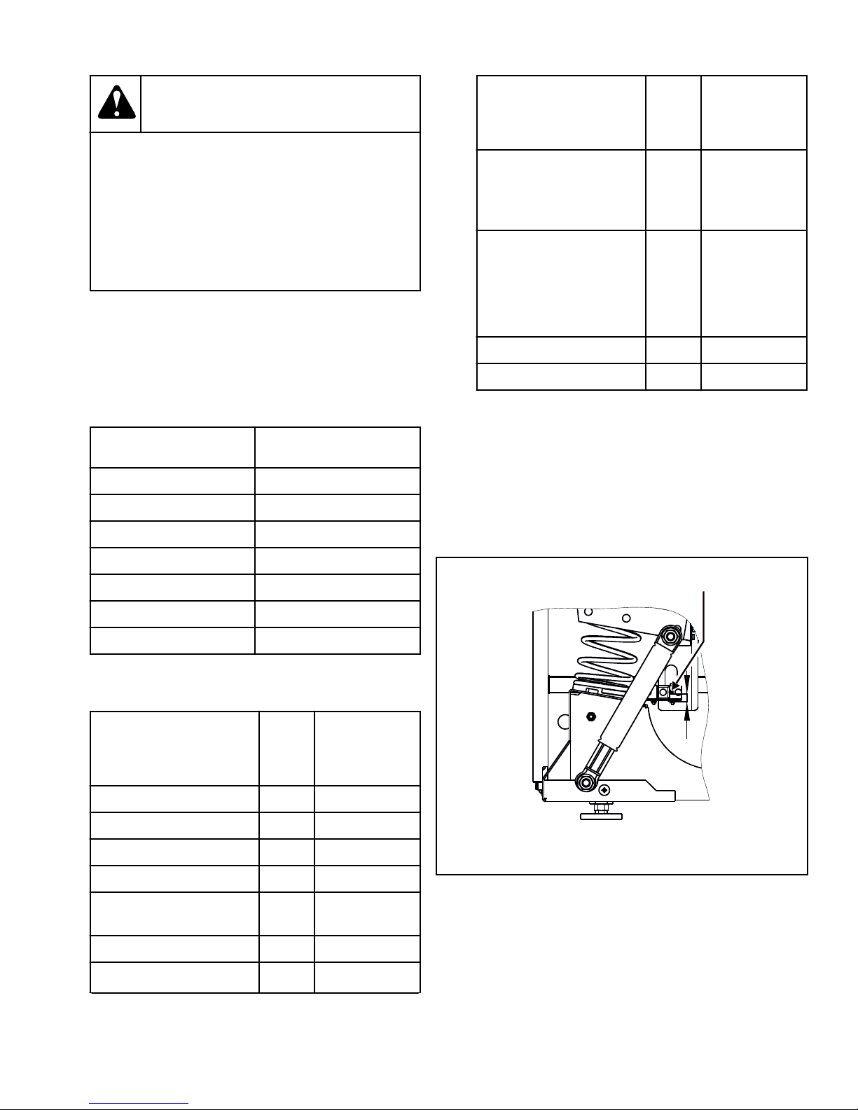
1
CFD1223N
A
Maintenance
WARNING
Before removing top or back panel of machine,
switch power off and wait for at least 10 minutes. Before starting inspection of frequency
inverter, check for residual voltage across
main circuit terminals. This voltage must be
below 30 VDC before you can access the inverter for inspection.
b. Motor cooling fins
c. Interior inverter ventilator (if present)
d. Exterior inverter ventilator (if present)
IMPORTANT: All torque joints must remain dry
(non-lubricated).
4. Check for belts for wear and inspect tightness. For recommended values, refer to Table 29 .
Model Torque, Hz
7 kg / 14 lb. / 65 L 67 - 70
8 kg / 20 lb. / 80 L 67 - 70
11 kg / 25 lb. / 105 L 65 - 68
14 kg / 30 lb. / 135 L 79 - 83
W905
Bolt
Item
Typ
e
Torque, lb.
ft. [Nm]
18 - 28 kg /
40 - 70 lb. /
180 - 280 L Models
External tub bolts -
M8 8.85 [12]
7 - 14 kg /
14 - 30 lb. /
65 - 135 L Models
Motor bolts M12 N/A
Spring holder bolts M8 7.38 [10]
Table 30
6. Adjust the safety switch.
NOTE: The safety switch is an important component
which must, if correctly adjusted, stop the machine
when excessive movement and shaking occur due
to an unbalance caused by improper distribution of
linen in the washing drum or when the amount of
laundry exceeds the machine capacity.
18 kg / 40 lb. / 180 L 64 - 69
24 kg / 55 lb. / 240 L 72 - 75
28 kg / 70 lb. / 280 L 72 - 75
Table 29
5. Check the tightness of bolts. Refer to Table 30 .
Bolt
Typ
Item
e
Bolts of the dampers M10 17.70 [24]
Bolts of the weight M8 19.18 [26]
Door lock bolts M5 1.84 [2.5]
Door handle central bolt M6 6.49 [8.8]
Door hinge and front panel
M6 6.49 [8.8]
bolts
Anchoring bolts M16 73.76 [100]
External tub bolts - M8 19.18 [26]
Torque, lb.
ft. [Nm]
1. Stick of safety switch
Figure 36
Table 30 continues...
©
Copyright, Alliance Laundry Systems LLC -
DO NOT COPY or TRANSMIT
53 Part No. D1625ENR4
Page 54
Maintenance
Specifica-
tion Model
Requirement, in.
[mm]
A - distance between lower edge
of lug and stick
of safety switch
7 kg - 14 kg /
14 lb. - 30 lb. /
65 L - 135 L
18 kg - 28 kg /
40 lb. - 70 lb. /
180 L - 280 L
Table 31
0.2 - 0.59 [5 - 15]
0 - 0.39 [0 - 10]
©
Copyright, Alliance Laundry Systems LLC -
DO NOT COPY or TRANSMIT
54 Part No. D1625ENR4
Page 55

Care of Stainless Steel
• Remove dirt and grease with detergent and water. Thoroughly
rinse and dry after washing.
• Avoid contact with dissimilar metals to prevent galvanic corrosion when salty or acidic solutions are present.
• Do not allow salty or acidic solutions to evaporate and dry on
stainless steel. Wipe clean of any residues.
• Rub in the direction of the polish lines or “grain” of the stainless steel to avoid scratch marks when using abrasive cleaners. Use stainless steel wool or soft, non-metal bristle brushes.
Do not use ordinary steel wool or steel brushes.
• If the stainless steel appears to be rusting, the source of the
rust may be an iron or steel part not made of stainless steel,
such as a nail or screw.
• Remove discoloration or heat tint from overheating by scouring with a powder or by employing special chemical solutions.
• Do not leave sterilizing solutions on stainless steel equipment
for prolonged periods of time.
• When an external chemical supply is used, ensure no siphoning of chemicals occurs when the machine is not in use. Highly concentrated chemicals can cause severe damage to stainless steel and other components within the machine. Damage
of this kind is not covered by the manufacturer’s warranty.
Locate the pump and tubing below the machine’s injection
point to prevent siphoning of chemicals into the machine.
Maintenance
©
Copyright, Alliance Laundry Systems LLC -
DO NOT COPY or TRANSMIT
55 Part No. D1625ENR4
Page 56
Disposal of Unit
MIX1N_SVG
Disconnecting the Machine
1. Switch off the external electric power inlet to machine.
2. Turn off the main switch on machine.
3. Shut the external water or stem inlet to machine.
4. Make sure the external electric power and steam inlets are
shut off. Disconnect all electric, water or steam inlets.
5. Insulate the external electric power inlet conductors.
6. Equip the machine with an "Out of Service" sign.
7. Unscrew nuts and bolts that fix machine to floor.
8. If the machine will never be used again, secure it so injury to
persons and damage to health, property and nature is avoided.
Remove the door, secure the drum so it does not turn and remove any sharp parts of machine so enclosure or injury of a
person or animal will not occur.
Disposal of Unit
household waste disposal service, or the source from which the
product was purchased.
CAUTION
Be careful when disconnecting machine from
service. Falling door and glass can cause injuries.
WARNING
Take all necessary action and precautions when
disassembling the washer to avoid injury from
glass or sharp metal edges.
Disposal of Unit
This appliance is marked according to the European directive
2002/96/EC on Waste Electrical and Electronic Equipment
(WEEE).
This symbol on the product or on its packaging indicates that this
product shall not be treated as household waste. Refer to Figure
37 . Instead it shall be handed over to the applicable collection
point for the recycling of electrical and electronic equipment. Ensuring this product is disposed of correctly will help prevent potential negative consequences for the environment and human
health which could otherwise be caused by inappropriate waste
handling of this product. The recycling of materials will help to
conserve natural resources. For more detailed information about
recycling of this product, please contact the local city office,
Figure 37
W922
W908
©
Copyright, Alliance Laundry Systems LLC -
DO NOT COPY or TRANSMIT
56 Part No. D1625ENR4
 Loading...