

Alliance Laundry Systems HY125_MICRO, IX275_MICRO, IX180_MICRO, IX230_MICRO, IXR180W Installation Operation & Maintenance
...Page 1

Washer-Extractors
Cabinet Freestanding
Refer to Page 8 for Model Identification
Installation/Operation/Maintenance
Original Instructions
Keep These Instructions for Future Reference.
(If this machine changes ownership, this manual must accompany machine.)
www.alliancelaundry.com
Part No. D1590ENR2
December 2014
Page 2

Page 3

Table of
Contents
Safety Information.............................................................................. 4
Explanation of Safety Messages........................................................... 4
Important Safety Instructions ............................................................... 4
Safety Decals ................................................................................... 7
Important Information Before Installation............................................ 7
Transportation and Storage .............................................................. 7
For Installation ................................................................................. 7
Machine Information ....................................................................... 7
Introduction......................................................................................... 8
Model Identification ............................................................................. 8
Replacement Parts ................................................................................ 9
Customer Service.................................................................................. 9
Technical Specifications ..................................................................... 10
75/335, 90/400 and 125/520 Models Without Tilt Option ................... 13
180/800, 230/1000 and 275/1200 Models Without Tilt Option ........... 15
180/800 Models With Tilt Option ........................................................ 17
230/1000 Models With Tilt Option ...................................................... 19
275/1200 Models With Tilt Option ...................................................... 21
Installation........................................................................................... 23
Handling, Transport and Storage.......................................................... 23
Transport and Storage ...................................................................... 23
Handling During Installation ........................................................... 23
Unpacking ........................................................................................ 23
Space Requirements.............................................................................. 23
Required Machine Working Conditions .......................................... 23
Size of a Laundry Room .................................................................. 23
Machine Positioning ............................................................................. 24
Machine Anchoring .............................................................................. 24
75/335, 90/400 and 125/520 Models .................................................... 25
180/800, 230/1000 and 275/1200 Models ............................................ 27
Machine Anchoring - 90/400 and 125/520 Models
With Tilt Option ................................................................................. 29
Machine Anchoring - 180/800, 230/1000 and 275/1200
Models With Tilt Option .................................................................... 30
Connections .......................................................................................... 31
Water Connection ............................................................................ 31
Water Consumption ......................................................................... 32
Water Drain Connection .................................................................. 32
Steam Connection ............................................................................ 32
Venting............................................................................................. 33
Electrical Connection....................................................................... 33
Liquid Soap Connection .................................................................. 39
Electrical Connection....................................................................... 40
Electronic Controller with Blue PCB and Graphical Display ......... 40
© Copyright 2014, Alliance Laundry Systems LLC
All rights reserved. No part of the contents of this book may be reproduced or transmitted in any form or by any
means without the expressed written consent of the publisher.
D1590ENR2
© Copyright, Alliance Laundry Systems LLC – DO NOT COPY or TRANSMIT
1
Page 4

Putting the Machine into Service.......................................................... 41
Models 75/335, 90/400 and 125/520 ............................................... 41
Models 90/400 and 125/520
with Tilt Option .............................................................................. 41
Models 180/800, 230/1000 and 275/1200 ....................................... 42
Checking Before Putting into Service.............................................. 42
Operation............................................................................................. 43
Symbols on the Machine ...................................................................... 43
Hanging Control (Washers with Tilting System) ............................ 44
Micro Microprocessor...................................................................... 45
Before Washing .................................................................................... 46
Opening the Door ................................................................................. 46
Loading the Machine with Linen.......................................................... 46
Closing the Door................................................................................... 46
Program Selection................................................................................. 46
Wash Programs Overview .................................................................... 47
Add Detergent....................................................................................... 47
Start the Washer.................................................................................... 48
Micro Microprocessor...................................................................... 48
End of Wash Cycle ............................................................................... 48
Models with the Tilt Option - Tilting the Machine Forward
to a Position Suitable for Unloading the Linen .............................. 48
Models with the Tilt Option - Unloading the Linen ........................ 49
Models with the Tilt Option - Tilting the Machine to the
Basic Position ................................................................................. 49
Maintenance ........................................................................................ 50
Introduction........................................................................................... 50
Daily ..................................................................................................... 50
Monthly or After 200 Working Hours.................................................. 50
Every 3 Months or After 500 Working Hours...................................... 50
Every 6 Months or After 1000 Working Hours.................................... 51
Safety Vibration Switch........................................................................ 51
Function Description - Models 75/335,
90/400 and 125/520 ........................................................................ 51
Function Description - Models 180/800, 230/1000
and 275/1200 .................................................................................. 51
Sensibility Adjustment - Models 75/335, 90/400
and 125/520 .................................................................................... 52
Sensibility Adjustment - Models 180/800, 230/1000
and 275/1200 .................................................................................. 52
Lubrication............................................................................................ 57
Lubrication Points, Quantity and Lubrication Periods -
Models 75/335, 90/400 and 125/520.............................................. 57
Lubrication Points, Quantity and Lubrication Periods -
Models 180/800,
230/1000 and 275/1200 .................................................................. 57
2
© Copyright, Alliance Laundry Systems LLC – DO NOT COPY or TRANSMIT
D1590ENR2
Page 5

Driving Mechanism .............................................................................. 58
Inspection of Belt Tightness ............................................................ 58
Belt Replacement ............................................................................. 58
Pulley Alignment ............................................................................. 58
Steam Filters ......................................................................................... 59
Cleaning the Filter............................................................................ 59
Thrust of Door Seal .............................................................................. 59
Adjusting on the Side of the Door Handle....................................... 59
Spring Unit - Models 75/335, 90/400 and 125/520 .............................. 61
Spring Unit - Models 180/800, 230/1000 and 275/1200...................... 62
Replacement Washer Fuses .................................................................. 62
Fuse Values...................................................................................... 62
Earth Leakage Trips.............................................................................. 62
The Test Procedure .......................................................................... 62
Troubleshooting Aids ......................................................................... 63
Door Blocking ...................................................................................... 63
Description of Door Lock Function................................................. 63
Lock without Tensions before the Program Start ............................ 63
Main Switch and Emergency Stop Button are Switched On ........... 63
Current Failure During Operation.................................................... 63
Unblocking the Door Lock in Case of Emergency.......................... 63
Error Indication Shown on Display ...................................................... 64
Putting the Machine out of Service ................................................... 65
Disconnecting the Machine .................................................................. 65
Machine Disposal ................................................................................. 66
Possibility of the Machine Disposal by a Specialized Company..... 66
Possibility of the Machine Liquidation by Own Potential............... 66
D1590ENR2
© Copyright, Alliance Laundry Systems LLC – DO NOT COPY or TRANSMIT
3
Page 6

Safety Information
Indicates an imminently hazardous
situation that, if not avoided, will cause
severe personal injury or death.
DANGER
Indicates a hazardous situation that, if not
avoided, could cause severe personal
injury or death.
WARNING
Indicates a hazardous situation that, if not
avoided, may cause minor or moderate
personal injury or property damage.
CAUTION
SAVE THESE INSTRUCTIONS FOR LATER
USE. Failure to comply with the
instructions may lead to incorrect use of
the appliance, and may result in risk of fire,
bodily injuries or death and/or damage to
the laundry and/or the appliance.
W828
WARNING
Read the IMPORTANT SAFETY
INSTRUCTIONS in this manual carefully
before operating the appliance. Improper
use of the appliance may cause risk of fire,
electrical shock or serious body injuries or
death as well as serious damage to the
appliance.
W829
WARNING
To reduce the risk of fire, electric shock,
serious injury or death to persons when
using your washer, follow these basic
precautions:
W023
WARNING
Explanation of Safety Messages
Precautionary statements (“DANGER,” “WARNING,”
and “CAUTION”), followed by specific instructions,
are found in this manual and on machine decals. These
precautions are intended for the personal safety of the
operator, user, servicer, and those maintaining the
machine.
Important Safety Instructions
This English version is the original version of this
manual. Without this version, the instructions are
incomplete.
Additional precautionary statements (“IMPORTANT”
and “NOTE”) are followed by specific instructions.
IMPORTANT: The word “IMPORTANT” is used
to inform the reader of specific procedures where
minor machine damage will occur if the procedure
is not followed.
NOTE: The word “NOTE” is used to communicate
installation, operation, maintenance or servicing
information that is important but not hazard
related.
4
© Copyright, Alliance Laundry Systems LLC – DO NOT COPY or TRANSMIT
Before installation, operation and maintenance of the
machine read carefully the complete instructions,
i.e., this “Installation, maintenance and user's
manual”, “Programming manual” and “Spare parts
manual”. The Spare parts manual is not delivered with
a machine by default. You shall ask the supplier/
manufacturer to obtain Spare parts manual.
1. Read all instructions before using the washer.
2. Install the washer according the
INSTALLATION instructions. Refer to the
EARTHING (grounding) instructions in the
INSTALLATION manual for the proper earthing
(grounding) of the washer. All connections for
water, drain, electrical power and earthing
(grounding) must comply with local codes and be
made by licensed personnel when required. It is
recommended that the machine be installed by
qualified technicians.
D1590ENR2
Page 7

Safety Information
3. Do not install or store the washer where it will be
exposed to water and/or weather.
4. To prevent fire and explosion, keep the area
around machine free from flammable and
combustible products. Do not add the following
substances or textiles containing traces of the
following substances to the wash water: gasoline,
kerosene, waxes, cooking oils, vegetable oils,
machine oils, dry-cleaning solvents, flammable
chemicals, thinners, or other flammable or
explosive substances. These substances give off
vapors that could ignite, explode or cause the
fabric to catch fire by itself.
5. Under certain conditions, hydrogen gas may be
produced in a hot water system that has not been
used for two weeks or more. HYDROGEN GAS
IS EXPLOSIVE. If the hot water system has not
been used for such a period, before using a
washing machine or combination washer-dryer,
turn on all hot water faucets and let the water
flow from each for several minutes. This will
release any accumulated hydrogen gas. The gas
is flammable, do not smoke or use an open flame
during this time.
6. To reduce the risk of an electric shock or fire, DO
NOT use an extension cord or an adapter to
connect the washer to the electrical power
source.
7. Do not allow children to play on or in the washer.
Close supervision of children is necessary when
the washer is used near children. This appliance
is not intended for use by young children or
infirm persons without supervision. Young
children should be supervised to ensure that they
do not play with the appliance. This is a safety
rule for all appliances.
8. DO NOT reach and/or climb into the tub or onto
the washer, ESPECIALLY if the wash drum is
moving. This is an imminently hazardous
situation that, if not avoided, will cause severe
personal injury or death.
9. Never operate the washer with any guards, panels
and/or parts removed or broken. DO NOT bypass
any safety devices or tamper with the controls.
10. Use washer only for its intended purpose,
washing textiles. Never wash machine parts or
automotive parts in the machine. This could
result in serious damage to the basket or tub.
11. Use only low-sudsing, no-foaming types of
commercial detergent. Be aware that hazardous
chemicals may be present. Wear hand and eye
protection when adding detergents and
chemicals. Always read and follow
manufacturer’s instructions on packages of
laundry and cleaning aids. Heed all warnings or
precautions. To reduce the risk of poisoning or
chemical burns, keep them out of the reach of
children at all times (preferably in a locked
cabinet).
12. Do not use fabric softeners or products to
eliminate static unless recommended by the
manufacturer of the fabric softener or product.
13. Always follow the fabric care instructions
supplied by the textile manufacturer.
14. Loading door MUST BE CLOSED any time the
washer is to fill, tumble or spin. DO NOT bypass
the loading door switch by permitting the washer
to operate with the loading door open. Do not
attempt to open the door until the washer has
drained and all moving parts have stopped.
15. Be aware that hot water is used to flush the
supply dispenser. Avoid opening the dispenser lid
while the machine is running.
16. Do not attach anything to the supply dispenser’s
nozzles, if applicable. The air gap must be
maintained.
17. Do not operate the machine without the water
reuse plug or water reuse system in place, if
applicable.
18. Be sure water connections have a shut-off valve
and that fill hose connections are tight. CLOSE
the shut-off valves at the end of each wash day.
19. Keep washer in good condition. Bumping or
dropping the washer can damage safety features.
If this occurs, have washer checked by a
qualified service person.
20. DANGER: Before inspecting or servicing
machine, power supply must be turned OFF. The
servicer needs to wait for at least 10 minutes after
turning the power OFF and needs to check for
residual voltage with a voltage meter. The
inverter remains charged with high voltage for
some time after powering OFF. This is an
imminently hazardous situation that, if not
avoided, will cause severe personal injury or
death. Before starting inspection of the inverter,
check for residual voltage across main circuit
terminals + and -. This voltage must be below 30
VDC before the servicer can access the inverter
for inspection.
21. Do not repair or replace any part of the washer, or
attempt any servicing unless specifically
recommended in the user-maintenance
instructions or in published user-repair
instructions that the user understands and has the
skills to carry out. ALWAYS disconnect the
washer from electrical, power and water supplies
before attempting any service.
22. Disconnect the power by turning off the circuit
breaker or by unplugging the machine. Replace
worn power cords.
23. Before the washer is removed from service or
discarded, remove the door to the washing
compartment.
24. Failure to install, maintain, and/or operate this
washer according to the manufacturer’s
instructions may result in conditions which can
produce bodily injury and/or property damage.
D1590ENR2
© Copyright, Alliance Laundry Systems LLC – DO NOT COPY or TRANSMIT
5
Page 8

Safety Information
This appliance must be connected to a
grounded metal, permanent wiring system,
and additionally an equipment-grounding
conductor must be run with the circuit
conductors and connected to the
equipment-grounding terminal or lead on
the appliance.
W830
WARNING
In order to minimize the risk of fire,
electrical shock and injury, THIS WASHER
MUST BE PROPERLY GROUNDED. Never
plug in or direct-wire an appliance unless it
is properly grounded in accordance with
all local and national codes. If more
appliances are in the same location,
mutual grounding must be applied where
possible.
W831
WARNING
It is recommended to consult static
requirements with a static engineer to
meet the requirements of permissible
loading, vibrations and noise level in the
building.
W839
WARNING
The washer extractor is intended to be
permanently connected, it MUST be
secured mounted to a NONCOMBUSTIBLE, adequate floor structure.
NEVER install the washer on an upper
floor or over a basement without a load
support designed by a structural engineer.
W832
WARNING
Always disconnect the washer from the
electrical supply before attempting any
service. The washer extractor is out of
tension if the main plug is taken out or
when the main supply is disconnected.
When the main switch is turned off the
inlet terminals of the machine main switch
are still under current!
W834
WARNING
CFD822N
W835
W836
Extreme hot conditions can arise in the air
around the machine. Watch out for vapor
that escapes from the washer extractor
venting!
W835
CAUTION
Do not cover the washer extractor venting.
It serves as a vapor outlet to prevent
pressure building in the washer extractor.
W836
CAUTION
NOTE: The WARNINGS and IMPORTANT
SAFETY INSTRUCTIONS appearing in this
manual are not meant to cover all possible
conditions and situations that may occur. Common
sense, caution and care must be exercised when
installing, maintaining, or operating the washer.
Always contact your dealer, distributor, service agent
or the manufacturer on any problems or conditions you
do not understand.
6
© Copyright, Alliance Laundry Systems LLC – DO NOT COPY or TRANSMIT
CFD822N
Figure 1
D1590ENR2
Page 9

Safety Information
Do not remove warning signs placed on
the appliance. Observe signs and labels to
avoid personal injuries. Safety labels
appear at crucial locations on the
appliance. Failure to maintain legible
safety labels could result in injury to the
operator or service technician.
W833
WARNING
Original or identical parts must be used for
replacement in this machine. After
servicing, replace and secure all panels in
the original way. Take these measures for
continued protection against electrical
shock, injury, fire and/or property damage.
W837
WARNING
Safety Decals
Important Information Before
Installation
For Installation
IMPORTANT: All connections must be performed
by qualified personnel with a proper authorization
according to this manual in compliance with local
standards
• The washer must not be installed or stored in an
area where it will be exposed to water and/or
weather. Avoid damp conditions where water or
moisture could run down the walls and covers of
the washer or cover the floor around the washer.
Do not install the washer above an open gutter.
Close any nearby gutters so that the waste water
steam cannot collect near/inside the washer.
• Any changes in the machine installation must be
approved by the dealer or manufacturer.
Otherwise, the dealer or manufacturer is not
responsible for possible injuries or damages.
Interference and changes in the machine
construction are not allowed and the
manufacturer refuses an responsibilities in such
cases.
• Define dangerous areas in the laundry room and
do not allow people to enter if the machine is in
operation.
Transportation and Storage
IMPORTANT: In case of transportation and
storage, watch components protruding from the
contour line of machine (door locks, etc.) to avoid
injuries.
• Never push, pull or exert pressure on components
protruding from the machine contour line
(controls, door locks, etc.).
• Make sure that these components are secured so
as to avoid damages during machine
manipulation and installation.
• In case of machine transportation by the
customer, follow the manufacturer’s instructions
for transportation, handling and storage of the
product. In case of transportation of the machine
by customer, the manufacturer is not responsible
for possible damage to the machine in the course
of transportation. In case of storing the machine
in a free area, it must be protected against
mechanical damage and weather conditions.
D1590ENR2
© Copyright, Alliance Laundry Systems LLC – DO NOT COPY or TRANSMIT
Machine Information
• This manual comprises information for the softmount machine series 75/335, 90/400, 125/520,
180/800, 230/1000 and 275/1200. Verify the
machine model according to your order and the
data plate located on the machine rear and find
corresponding information in the manual.
• The machines are controlled by electronic
controller. Find the programming instructions in
the Programming Manual.
• Additional heating can be provided by electrical
heating elements or by steam from an external
steam supply.
• Water inlets can use warm, cold, soft and cold
hard water. A machine can be equipped with
recycled discharging, dosing pumps for liquid
soaps and/or a tilting system.
• Electrical setup of the machine is indicated on the
data plate (Figure 2, pos. 11).
7
Page 10

Introduction
Model Identification
Information in this manual is applicable to the
following models:
HY125_MICRO
HY90_MICRO
HYN125W
HYN90W
IX180_MICRO
IX230_MICRO
IX275_MICRO
IXR180W
IXR230W
IXR275W
IY125_MICRO
IY180_MICRO
IY230_MICRO
IY275_MICRO
IY90_MICRO
IYN090W
IYN125W
SY125_MICRO
SY90_MICRO
SYN090W
SYN125W
UX180_MICRO
UX230_MICRO
UX275_MICRO
UXR180W
UXR230W
UXR275W
UY125_MICRO
UY180_MICRO
UY230_MICRO
UY275_MICRO
UY90_MICRO
UYN090W
UYN125W
UYN180W
UYN230W
UYN275W
8
© Copyright, Alliance Laundry Systems LLC – DO NOT COPY or TRANSMIT
D1590ENR2
Page 11

Replacement Parts
If literature or replacement parts are required, contact
the source from which the machine was purchased or
contact Alliance Laundry Systems at
+1 (920) 748-3950 for the name and address of the
nearest authorized parts distributor.
Customer Service
Contact your local distributor or call:
Alliance Laundry Systems
Shepard Street
P.O. Box 990
Ripon, WI 54971-0990
U.S.A.
www.alliancelaundry.com
Phone: +1 (920) 748-3121
Ripon, Wisconsin
Alliance International
+3256412054
Wevelgem, Belgium
Introduction
D1590ENR2
© Copyright, Alliance Laundry Systems LLC – DO NOT COPY or TRANSMIT
9
Page 12

Technical Specifications
Specification
Machine Dimensions
Width
Depth
Height
1
– Models Without Tilt Option
mm/inch
mm/inch
mm/inch
75/335 90/400 125/520 180/800 230/1000 275/1200
1195/47.04
1330/52.40
1905/75.00
1195/47.04
1430/56.30
1905/75.00
1195/47.04
1610/63.40
1905/75.00
1495/58.86
1940/76.38
1985/78.15
1790/70.47
2005/78.94
2060/81.10
1855/73.03
2085/82.09
2085/82.09
Machine Dimensions1 – Models With Tilt Option
Width
Depth
Height
mm/inch
mm/inch
mm/inch
-
-
-
-
-
-
-
-
-
1565/61.61
2020/79.53
2215/87.20
1855/73.03
2100/82.68
2300/90.55
1895/74.61
2155/84.84
2335/91.93
Packing Dimensions – Models Without Tilt Option
Width
Depth
Height
Transportation volume
mm/inch
mm/inch
mm/inch
m³/ft³
1430/56.30
1475/58.10
2105/82.90
4.4/156
1430/56.30
1570/61.80
2105/82.90
4.7/166
1430/56.30
1750/68.90
2105/82.90
5.3/187
1690/66.53
1950/76.77
2200/86.61
7.25/256
1865/73.42
2125/83.66
2345/92.33
9.29/328
2000/78.73
2170/85.43
2340/92.12
10.16/359
Packing Dimensions – Models With Tilt Option
Width
Depth
Height
Transportation volume
mm/inch
mm/inch
mm/inch
m³/ft³
-
-
-
-
-
-
-
-
-
-
-
-
1690/66.54
2075/81.69
2440/96.06
8.90/314
2040/80.31
2375/93.50
2490/98.03
11.85/419
2040/80.31
2375/93.50
2490/98.03
12.42/439
Drum Dimensions
Diameter
Depth
Drum volume
Door opening
mm/inch
mm/inch
dm³/gal.
mm/inch
914/36.00
510/20
335/88
540/21.30
914/36.00
610/24
400/106
540/21.30
914/36.00
790/31.10
518/137
540/21.30
1110/43.70
838/33
807/213
530/20.86
1200/47.24
860/33.85
1003/265
530/20.86
1300/51.18
870/34.25
1180/312
650/25.59
Weight – Models Without Tilt Option
Net
Gross
kg/lb.
kg/lb.
1190/2623
1310/2888
1560/3439
1700/3748
1630/3594
1770/3902
2640/5820
2830/6239
3170/6989
3410/7518
3480/7672
3710/8179
Weight – Models With Tilt Option
Net
Gross
kg/lb.
kg/lb.
-
-
-
-
-
-
2990/6592
3210/7077
3520/7761
3760/8290
3840/8466
4060/8951
Electrical Data
Power supply deviations
Motor output kW
3x380-415V 50/60Hz
3x440-480V 50/60Hz
3x200-240V 50/60Hz
-6% to +10% of the voltage supply ±1 Hz
4 7.5 7.5 11 15 18.5
3x208-240V 50/60Hz
3x380-480V 50/60HZ
Input Power
Electric heating
24kW kW
Electric heating
36kW kW
Electric heating
54kW (380-480V) kW
Electric heating
67.5kW kW
28.1 - - - - -
- 43.6 - - - -
--61.6---
---75--
Steam or without heating kW 4.1 7.6 7.6 11.25 15.25 18.75
10
© Copyright, Alliance Laundry Systems LLC – DO NOT COPY or TRANSMIT
Table 1 (Continued)
D1590ENR2
Page 13

Table 1 (Continued)
Specification
75/335 90/400 125/520 180/800 230/1000 275/1200
Supply Protection Device Use slow type Protection devices (circuit breakers: curve D)
Residual current device
(RCD) mA
100, class B 100, class B 100, class B 100, class B 100, class B 100, class B
Steam or without heating
200-240V 3AC
380-480V 3AC
3x208-240V 50/60Hz
3x380-480V 50/60 Hz
A
A
A
A
El. Heating 24kW (220-240V) A
El. Heating 24kW (380-415V) A
El. Heating 24kW (440-480V) A
El. Heating 36kW (200-240V) A
El. Heating 36kW (380-480V) A
El. Heating 54kW (220-240V) A
El. Heating 54kW (380-480V) A
El. Heating 67.5kW (3x208-240V) A
El. Heating 67.5kW (3x208-240V) A
30
16 (15)
-
-
80
50
32
-
-
-
-
-
-
40
20
-
-
-
-
-
120
80
-
-
-
-
40
20
-
-
-
-
-
-
160
100
-
-
Washing Functions
Washing
High extracting
G-factor
RPM
RPM
38
830
350 350 350 350 350 350
38
830
38
830
Connection Data
Water inlet connection inch
Water pressure range MPa/bar/PSI
Recommended
water pressure
MPa/bar/PSI
Maximal water temperature °C/°F
Drain diameter mm/inch
Drain flow rate
dm³ min
gal. min
-1
-1
Steam connection inch
Steam pressure MPA/bar/PSI
Press air connection
2
mm/inch
Not lubricated air pressure MPa/bar/PSI
Powder dispenser cups
Liquid soap signals
External liquid soap connections
Hose for press air
connection
(Models with tilt
mm/inch
option only)
90/194 90/194 90/194 90/194 90/194 90/194
2 x 76/3 2 x 76/3 2 x 76/3 2 x 10³/4 2 x 10³/4 2 x Ø103/4
300
80
G 3/4 in. G 3/4 in. G 3/4 in. G 1 in. G 1 in. G 1 in.
6/0.25 6/0.25 6/0.25 8/0.30 8/0.30 Ø 8/0.30
0.3 - 0.5/3 5/43 - 73
5
8 pumps
666
-
BSP 1” 3 x BSP 1½”
0.1 - 0.8/1 - 8/14.5 - 116
0.3 - 0.5/3 - 5/43 - 73
300
80
0.3 - 0.5/3 5/43 - 73
5
8 pumps
8/0.31
outside
diameter
300
80
0.3 - 0.5/3 - 5/43 - 73
0.3 - 0.5/3 5/43 - 73
5
8 pumps
8/0.31
outside
diameter
0.6/6/87 0.6/6/87 0.6/6/87
8 pumps
6 tubes:
1 x ½ in.
diameter
outside
Air pressure
(Models with tilt
MPa/bar/PSI
- 0.35/3.5/51 0.35/3.5/51 0.35/3.5/51 0.35/3.5/51 0.35/3.5/51
option only)
Motor Size KW/HP
4.0/5.36 7.5/10.06 7.5/10.06 11.0/14.75 15.0/20.12 18.5/24.81
Technical Specifications
-
63
32
-
-
-
-
-
-
-
250
125
36
750
540
142
5
8/0.31
-
75
50
-
-
-
-
-
-
-
-
-
33
720
516
136
5
8 pumps
6 tubes:
1 x ½ in.
8/0.31
outside
diameter
-
-
100
63
-
-
-
-
-
-
-
-
-
32
695
516
136
5
8 pumps
1 x ½ in.
8/0.31
outside
diameter
D1590ENR2
© Copyright, Alliance Laundry Systems LLC – DO NOT COPY or TRANSMIT
Table 1 (Continued)
11
Page 14

Technical Specifications
Specification
General Data
Ambient temperature
°C/°F
Relative humidity
Height above sea level
Storage temperature
Max. static load on floor
m/ft.
°C/°F
kN
(Models without tilt
option)
Max. static load on floor
kN
(Models with tilt option)
Max. dynamic load on
kN
floor (Models without tilt
option)
Max. dynamic load on
kN
floor (Models with tilt
option)
Frequency of dynamic
Hz
load
Sound Levels
L
wash/extraction seq. db
Aeq
1
maximum dimensions including protruding parts
2
washers with air operated water valves
3
ISO 3744
3
Table 1 (Continued)
75/335 90/400 125/520 180/800 230/1000 275/1200
5 to 35/41 to 95
30% to 90% without condensation
up to 1000/3280
1 to 55/34 to 131
14.41
-
12.7 ± 2.74
-
14
55/75 55/75 55/75 51/71 52/72 52/72
18.16
19.4
16.08 ± 2.94
17.11 ± 2.94
14
19.57
20.86
17.06 ± 3.13
18.13 ± 3.13
14
30.9
34.4
27.2 ± 4.5
30.6 ± 4.5
12.5
36.9
40.4
32.7 ± 5.5
36.1 ± 5.5
12.1
40.4
43.9
36.0 ± 7.0
39.5 ± 7.0
11.7
Table 1
12
© Copyright, Alliance Laundry Systems LLC – DO NOT COPY or TRANSMIT
D1590ENR2
Page 15

75/335, 90/400 and 125/520 Models Without Tilt Option
18
15
G
X
A
AA
1
H
K
T
A1
R
D1
P
C
B
F
Z
D
E
L
C1
J
O
MN
Q
B1
S
U
WV
H1
2
3
13
16
4
56 7 8 9
11
13
10
19
G1
17
12
1414
CFD988N
NOTE: Refer to following page for dimensions.
Technical Specifications
1 Operator Panel 11 Data plate
2 Tub ventilation (60 mm/2.4 in.) 12 Steam inlet
3 Lubrication points 13 Equipotential bounding terminal
4 Entry soap supply cable 14 Drain outlet
5 Entry main power cable 15 Soap dispenser air relieve
6 Main switch 16 Frequency inverter cover
7 Hard cold water inlet 17 Compressed air inlet
8 Hot water inlet (Models with air operated water valves)
9 Soft cold water inlet 18 Soap dispenser
10 Hose connection soap supply 19 Electrical signals liquid soap
Figure 2
D1590ENR2
© Copyright, Alliance Laundry Systems LLC – DO NOT COPY or TRANSMIT
13
Page 16

Technical Specifications
Machine Dimensions – Models Without Tilt Option
MACHINE 75/335 90/400 125/520
A
A1
B
B1
C
C1
D
D1
E
F
G
G1
H
H1
J
K
L
M
N
O
P
P*
Q
R
S
T
U
V
W
X
Z
AA
* Models with air-operated water valves
mm/inch 1195/47.04 1195/47.04 1195/47.04
mm/inch 1361/53.58 1361/53.58 1361/53.58
mm/inch 1905/75 1905/75 1905/75
mm/inch 116/4.56 116/4.56 116/4.56
mm/inch 1055/41.54 1055/41.54 1055/41.54
mm/inch 980/38.58 980/38.58 980/38.58
mm/inch 1330/52.4 1430/56.3 1610/63.39
mm/inch 1600/62.99 1600/62.99 1600/62.99
mm/inch 1222/48.11 1322/52.05 1502/59.13
mm/inch 300/11.8 300/11.8 300/11.8
mm/inch 50/1.97 50/1.97 50/1.97
mm/inch 110/4.33 110/4.33 110/4.33
mm/inch 1617/63.66 1617/63.66 1617/63.66
mm/inch 25/0.98 25/0.98 25/0.98
mm/inch 730/28.74 730/28.74 730/28.74
mm/inch 1567/61.69 1567/61.69 1567/61.69
mm/inch 422/16.61 422/16.61 422/16.61
mm/inch 80/3.15 80/3.15 80/3.15
mm/inch 80/3.15 80/3.15 80/3.15
mm/inch 70/2.75 70/2.75 70/2.75
mm/inch 1782/70.16 1782/70.16 1782/70.16
mm/inch 1672/65.82 1672/65.82 1672/65.82
mm/inch 60/2.36 60/2.36 60/2.36
mm/inch 1285/50.59 1285/50.59 1285/50.59
mm/inch 65/2.56 65/2.56 65/2.56
mm/inch 768/30.24 768/30.24 768/30.24
mm/inch 205/8.07 205/8.07 205/8.07
mm/inch 213/8.39 213/8.39 213/8.39
mm/inch 420/16.54 275/10.83 275/10.83
mm/inch 175/6.89 175/6.89 175/6.89
mm/inch 700/27.56 700/27.56 700/27.56
mm/inch 730/28.74 730/28.74 730/28.74
14
© Copyright, Alliance Laundry Systems LLC – DO NOT COPY or TRANSMIT
Table 2
D1590ENR2
Page 17

180/800, 230/1000 and 275/1200 Models Without Tilt Option
A
B
E
F
D
R
Z
Q
O
P
V
S
T
X
Y
C
U
M
N
G
HIJKL
W
16
14
15
67
13
5
9
10
11
12
17
4
8
1220319
18
NOTE: Refer to following page for dimensions.
Technical Specifications
1 Box of electrical components 10 Hard cold water inlet
2 Soap dispenser ventilation 11 Soft cold water inlet
3 Control panel 12 Hot water inlet
4 Soap dispenser 13 Compressed air inlet
5 Electrical signals liquid soap 14 Entry main power cable
6 Steam inlet 15 Main switch
7 Tub ventilation 16 Drain outlet
8 Cover for pneumatic components 17 Electric switchboard cover
9 Hose connection soap supply 18 Serial label
CFD945N
Figure 3
D1590ENR2
© Copyright, Alliance Laundry Systems LLC – DO NOT COPY or TRANSMIT
15
Page 18

Technical Specifications
MACHINE 180/800 230/1000 275/1200
A
B
C
D
E
F
G
H
I
J
K
L
M
N
O
(1)
P
Q
R
S
T
U
V
W
X
Y
(2)
Z
(1)
Height of item 9
(2)
Height of items 6, 7, 10, 11 and 12
mm/inch 1495/58.86 1790/70.47
mm/inch 1985/78.15 2060/81.10
mm/inch 1940/76.38 2005/78.94
mm/inch 1390/54.72 1688/66.46
mm/inch 1133/44.60 1175/46.26
mm/inch 1020/40.16 1095/43.11
mm/inch 303/11.93 232/9.13
mm/inch 168/6.61 232/9.13
mm/inch 125/4.92 125/4.92
mm/inch 125/4.92 125/4.92
mm/inch 90/3.54 124/4.88 120/4.72
mm/inch 100/3.93 110/4.33 148/5.83
mm/inch 83/3.27 83/3.27
mm/inch 210/8.26 210/8.26
mm/inch 1900/74.80 1518/59.76
mm/inch 1787/70.35 1405/55.31
mm/inch 1983/78.07 1950/76.77
mm/inch 1460/57.48 1754/69.05
mm/inch 282/11.10 268/10.55
mm/inch 437/17.20 419/16.50
mm/inch 662/26.06 696/27.40
mm/inch 735/28.93 768/30.24
mm/inch 197/7.76 197/7.76
mm/inch 380/14.96 527/20.75
mm/inch 665/26.18 650/25.59
mm/inch 1787/70.53 1836/72.28
Machine Dimensions – Models Without Tilt Option
1855/73.03
2085/82.09
2085/82.09
1754/69.05
1200/47.24
1080/42.52
295/11.61
247/9.72
125/4.92
125/4.92
83/3.27
210/8.26
1548/60.94
1435/56.50
1980/77.95
1820/71.65
243/9.57
394/15.51
722/28.43
795/31.30
197/7.76
562/22.13
757/29.80
1866/73.46
16
© Copyright, Alliance Laundry Systems LLC – DO NOT COPY or TRANSMIT
Table 3
D1590ENR2
Page 19

180/800 Models With Tilt Option
FRONT VIEW
LEFT SIDE VIEW
BACK VIEW
VIEW FROM ABOVE
A
G
F
D
C
B
E
H
J
I
K
L
M
V
T
U
S
R
P
Q
N
O
LEFT SIDE VIEW OF TILTING
FRONT VIEW OF TILTING
W
X
Y
Z
AA
NOTE: Refer to following page for dimensions.
Technical Specifications
CFD980N
CFD980N
Figure 4
D1590ENR2
© Copyright, Alliance Laundry Systems LLC – DO NOT COPY or TRANSMIT
17
Page 20

Technical Specifications
Dimensions 180/800
A
B
C
D
E
F
G
H
I
J
K
L
M
N
O
P
Q
R
S
T
U
V
W
X
Y
Z
AA
Machine Dimensions – Models With Tilt Option
mm/inch 2215/87.20
mm/inch 1908/75.12
mm/inch 1850/72.83
mm/inch 1037/40.83
mm/inch 988/38.90
mm/inch 1565/61.61
mm/inch 1019/40.12
mm/inch 2020/79.53
mm/inch 705/27.76
mm/inch 468/18.43
mm/inch 491/19.33
mm/inch 155/6.10
mm/inch 407/16.02
mm/inch 140°
mm/inch 424/16.69
mm/inch 146°
mm/inch 541/21.30
mm/inch 219/8.62
mm/inch 966/38.03
mm/inch 851/33.50
mm/inch 812/31.97
mm/inch 2476/97.48
mm/inch 983/38.70
mm/inch 837/32.95
mm/inch 15°
mm/inch 2380/93.70
mm/inch 2009/79.09
18
© Copyright, Alliance Laundry Systems LLC – DO NOT COPY or TRANSMIT
Table 4
D1590ENR2
Page 21

230/1000 Models With Tilt Option
CFD981N
FRONT VIEW
LEFT SIDE VIEW
BACK VIEW
VIEW FROM ABOVE
A
G
F
D
C
B
E
H
J
I
K
L
M
V
T
U
S
R
P
Q
N
O
LEFT SIDE VIEW OF TILTING
FRONT VIEW OF TILTING
W
X
Y
Z
AA
NOTE: Refer to following page for dimensions.
Technical Specifications
D1590ENR2
© Copyright, Alliance Laundry Systems LLC – DO NOT COPY or TRANSMIT
Figure 5
CFD981N
19
Page 22

Technical Specifications
Dimensions 230/1000
A
B
C
D
E
F
G
H
I
J
K
L
M
N
O
P
Q
R
S
T
U
V
W
X
Y
Z
AA
Machine Dimensions – Models With Tilt Option
mm/inch 2300/90.55
mm/inch 2004/78.9
mm/inch 1946/76.61
mm/inch 1158/45.59
mm/inch 1062/41.81
mm/inch 1855/73.03
mm/inch 1095/43.11
mm/inch 2100/82.68
mm/inch 695/27.36
mm/inch 610/24.02
mm/inch 511/20.12
mm/inch 155/6.10
mm/inch 326/12.83
mm/inch 140°
mm/inch 445/17.52
mm/inch 150°
mm/inch 527/20.75
mm/inch 103/4.06
mm/inch 1045/41.14
mm/inch 932/36.69
mm/inch 900/35.43
mm/inch 2575/101.38
mm/inch 1027/40.43
mm/inch 881/34.69
mm/inch 15°
mm/inch 2534/99.76
mm/inch 2098/82.60
20
© Copyright, Alliance Laundry Systems LLC – DO NOT COPY or TRANSMIT
Table 5
D1590ENR2
Page 23
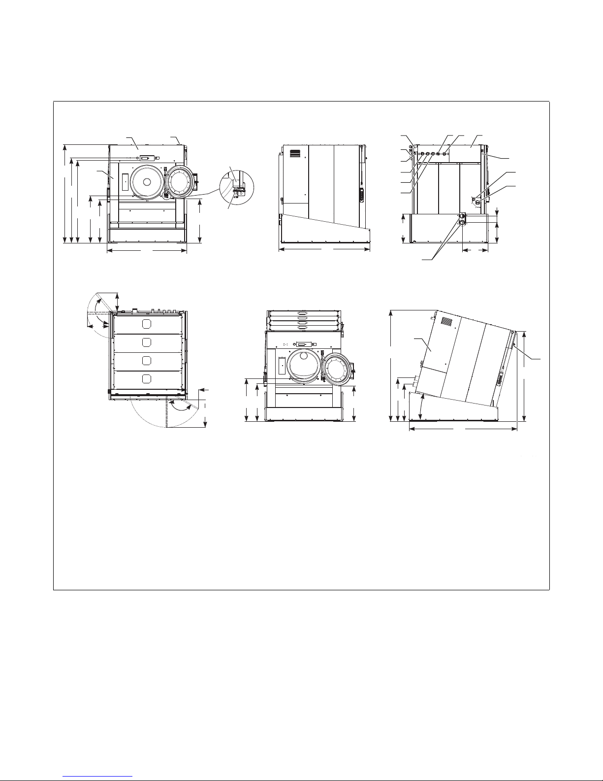
275/1200 Models With Tilt Option
L
K
J
I
H
G
F
E
D
C
B
A
T US
R
Q
P
O
N
M
Z
AA
Y
X
W
V
4
5
9
10
11
12
6 7 8
13
14
15
16
1
3
2
17
18
FRONT VIEW
LEFT SIDE VIEW
BACK VIEW
VIEW FROM ABOVE LEFT SIDE VIEW OF TILTING
FINGER
COMPLETE
FRONT VIEW OF TILTING
DOOR SECURING
FINGER BACKSTOP
NOTE: Refer to following page for dimensions.
Technical Specifications
1 Box of electrical components 10 Hard cold water inlet
2 Soap dispenser ventilation 11 Soft cold water inlet
3 Control panel 12 Hot water inlet
4 Soap dispenser 13 Compressed air inlet
5 Electrical signals liquid soap 14 Entry main power cable
6 Steam inlet 15 Main switch
7 Tub ventilation 16 Drain outlet
8 Cover for pneumatic components 17 Electric switchboard cover
9 Hose connection soap supply 18 Serial label
Figure 6
CFD961N
D1590ENR2
© Copyright, Alliance Laundry Systems LLC – DO NOT COPY or TRANSMIT
21
Page 24

Technical Specifications
Dimensions 275/1200
A
B
C
D
E
F
G
H
I
J
K
L
M
N
O
P
Q
R
S
T
U
V
W
X
Y
Z
AA
Machine Dimensions – Models With Tilt Option
mm/inch 2335/91.93
mm/inch 2015/79.33
mm/inch 1957/77.05
mm/inch 1149/45.20
mm/inch 1048 /41.26
mm/inch 1895/74.61
mm/inch 1082/42.60
mm/inch 2155/84.84
mm/inch 695/27.36
mm/inch 610/24.02
mm/inch 492/19.37
mm/inch 155/6.10
mm/inch 429/16.89
mm/inch 140°
mm/inch 511/20.12
mm/inch 271/10.67
mm/inch 150°
mm/inch 651/25.63
mm/inch 1030/40.55
mm/inch 916/36.06
mm/inch 868/34.17
mm/inch 2628/103.46
mm/inch 1028/40.47
mm/inch 882/34.72
mm/inch 15°
mm/inch 2553/100.51
mm/inch 2124/83.62
22
© Copyright, Alliance Laundry Systems LLC – DO NOT COPY or TRANSMIT
Tab le 6
D1590ENR2
Page 25
Installation
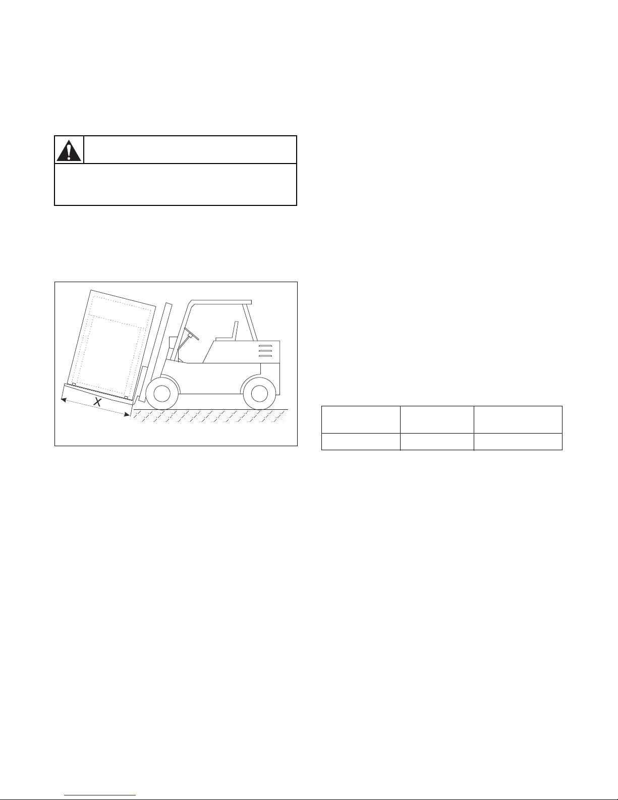
Forks of lift truck must have sufficient
length.
W838
WARNING
Handling, Transport and Storage
Transport and Storage
Use a lift truck or a manual skid cart for handling the
machine while in the transport package. If possible,
leave the machine in the transport package or at least
let it sit on the transport wooden skid until the time of
final installation on the foundation.
NOTE: Make sure that these components are
secured to avoid damage during handling and
installation of the machine.
3. Make sure that the filling door is secured to avoid
its opening during handling.
4. Lift the machine up by lift truck using a transport
skid to which the machine has been attached.
Unpacking
After unpacking, check for any damage to the machine
and that all accessories have been included with your
order. Verify the type of your machine by the data
plate located on the machine rear and find
corresponding information in the manual. The
accessories and the manual are located inside of the
drum, according to the information found in Door
Blocking.
Before the machine can be installed, remove the
packaging, loosen four nuts and lift the machine
carefully up. Make sure not to damage the machine
components located in the machine’s lower part. The
lift truck forks must be at least 10 cm longer than the
length of the washing machine frame (Tabl e 7 ).
CFD824N
Figure 7
Handling During Installation
All activities should only be done by a worker who
knows all information about the machine. The
machine is delivered to the customer in a wooden skid
packaging and protected with polyethylene film. The
machine is attached to the skid by means of four bolts
M16.
To remove the machine to its final location, follow
these precautions:
1. All passages and spaces the machine has to be
transported through at installation should be
reasonably dimensioned to meet the height and
width of the machine including the packaging.
2. Never push, pull or press the components
protruding from the contour line of the machine
(front part, filling door, control elements, belt
cover, water inlet, outlet pipes, etc.).
75/335, 90/400
and 125/520
1500 mm/59 in. 1800 mm/71 in. 2000 mm/78.73 in.
180/800
Table 7
230/1000 and
275/1200
Space Requirements
Required Machine Working Conditions
See Technical Specifications section.
The washer must not be installed or stored in an area
where it will be exposed to water and/or weather.
Avoid damp conditions where water or moisture could
run down the walls and covers of the washer or cover
the floor around the washer. Do not install the washer
above an open gutter. Close any nearby gutters so that
waste water steam cannot collect near/inside the
washer.
Size of a Laundry Room
IMPORTANT: Ignoring the requirement for spaces
between machines and walls can make service and
maintenance work difficult.
D1590ENR2
© Copyright, Alliance Laundry Systems LLC – DO NOT COPY or TRANSMIT
23
Page 26
Installation
It is recommended to consult static
requirements with a static engineer to
meet the requirements of permissible
loading, vibrations and noise level in the
building.
W839
WARNING
The washer extractor is intended to be
permanently connected, it MUST be
secured mounted to a NONCOMBUSTIBLE, adequate floor structure.
NEVER install the washer on an upper
floor or over a basement without a load
support designed by a structural engineer.
W832
WARNING
The nuts of the anchoring bolts have to be
tightened by means of a torque - limiting
wrench. Do not tighten the nuts of
anchoring bolts before the concrete base
around the bolts is completely cured.
W840
WARNING
Machine Positioning
Total space requirements for the system installation
are usually determined by a detailed plan of the
building. The machine dimensions are stated in the
Technical Specifications section.
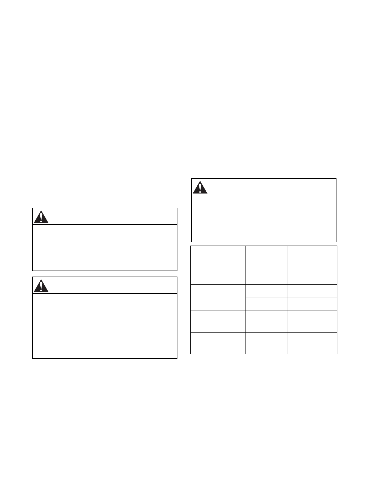
Leave at least 1 m (39.36 inches) of space between the
machine rear and the wall for maintenance access. On
the left side of the machine a minimum of 620 mm
(24.5 inches) is needed and 250 mm (10 inches) on the
right side. Between the lateral sides of each machine, it
is recommended to leave a space of 0.7 m (27.55
inches) for 75/335, 90/400 and 125/520 models and
0.8 m (31.49 inches) for 180/800, 230/1000 and 275/
1200 models. There must be a minimum of 0.7 m
(27.55 inches) of free space above the machine for
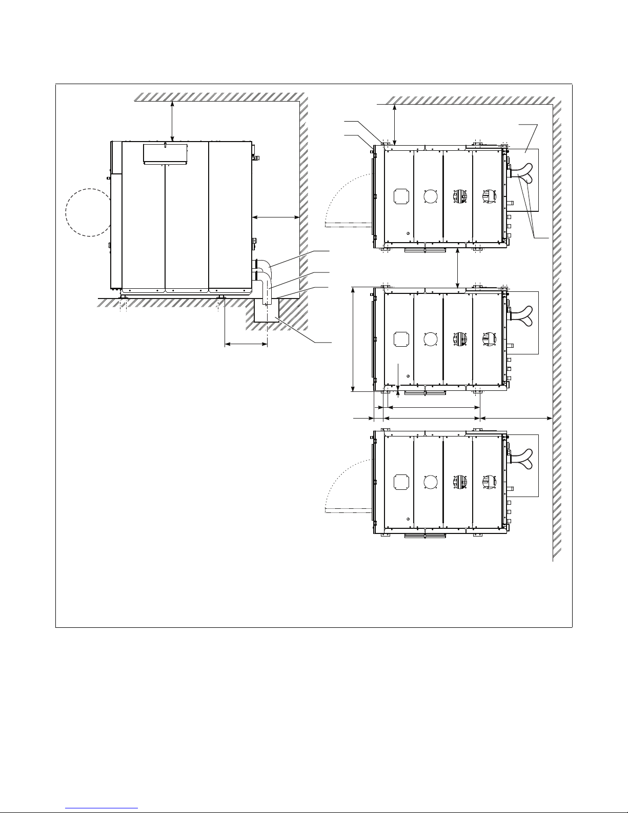
maintenance access. Refer to Figure 8 and Tabl e 9 .
The waste piping or outlet channel must be
dimensioned to the discharged water quantity and the
number of washing machines.
Machine Anchoring
IMPORTANT: Anchoring the machine is necessary
when the floor is uneven, may become slippery, or
is constructed of variable surfaces. Anchoring the
machine is also necessary in any cases where there
is a risk of the machine moving along the floor’s
surface during operation.
The machine is to be located on a leveled concrete
floor to comply with static and dynamic stress of the
machine. Check the position of the machine base
frame using a level. The manufacturer is not
responsible for consequences caused by a wrong
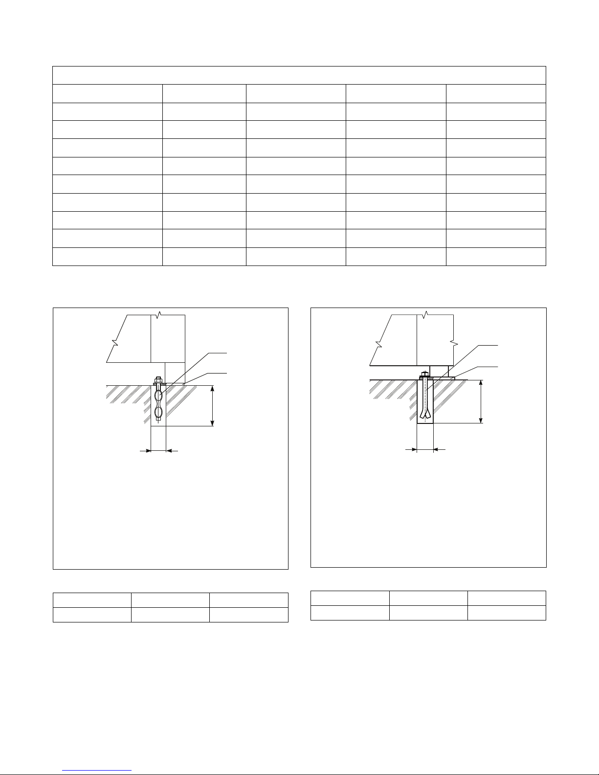
installation. Refer to Figure 8 and Tabl e 10 for
75/335, 90/400 and 125/520 models without the tilt
option or to Figure 9 and Tab le 11 for 180/800, 230/
1000 and 275/1200 models without the tilt option for
mounting bolt specifications. Please refer to Figure 13
and Tab l e 1 3 for the mounting bolt specifications for
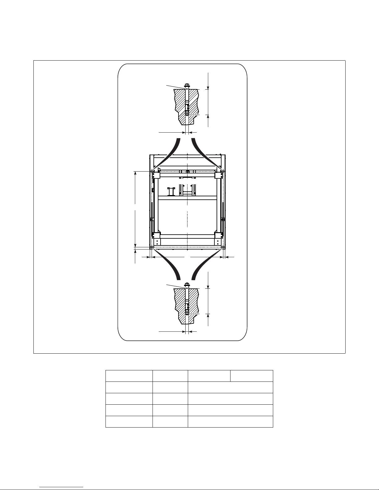
models with the tilt option.
24
© Copyright, Alliance Laundry Systems LLC – DO NOT COPY or TRANSMIT
Model Hardware
75/335, 90/400 and
125/520 Models
Without Tilt Option
75/335, 90/400 and
125/520 Models With
Tilt Option
180/800, 230/1000
and 275/1200 Models
Without Tilt Option
180/800, 230/1000
and 275/1200 Models
With Tilt Option
M16 x 160 210/155
Anchoring Bolt 80/59
Threaded Rod 133/98
M10 x 160 49/36
Anchoring Bolt 80/59
Table 8
Torque Value
(Nm/lb.-ft.)
D1590ENR2
Page 27
75/335, 90/400 and 125/520 Models
X19X2
X1
X9
X5
X6
X10
X12
X4
1
2
X15
X16
X17
3
4
700 mm
27.55”
X13
X14
X18
X3
4
5
3
X11
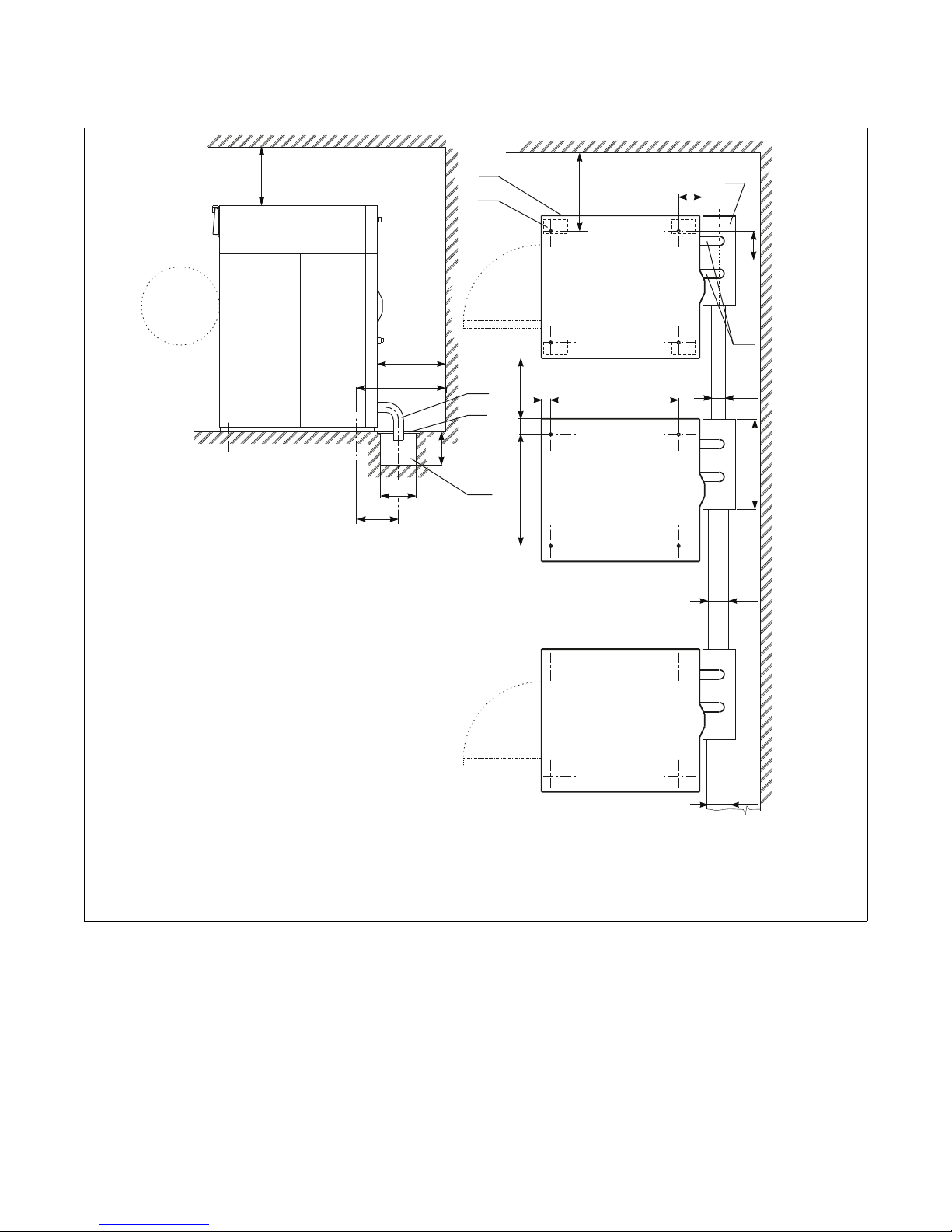
Installation
1 Machine line of contour 4 Draining elbow
2 Machine footing 5 Cover of waste sump
3 Waste sump
Figure 8
CFD963N
D1590ENR2
© Copyright, Alliance Laundry Systems LLC – DO NOT COPY or TRANSMIT
25
Page 28
Installation
Machine Positioning
Dimensions 75/335 90/400 125/520
X1 mm/inch
X2 mm/inch
X3 mm/inch
X4 mm/inch
X5 mm/inch
X6 mm/inch
X9 mm/inch
X10 mm/inch
X11 mm/inch
X12 mm/inch
X14 mm/inch
X15 mm/inch
X16 mm/inch
X17 mm/inch
X18 mm/inch
X19 mm/inch
970/38.18 1070/42.13 1250/49.21
930/36.61 930/36.61 930/36.61
1175/46.25 1175/46.25 1175/46.25
830/32.67 830/32.67 830/32.67
130/5.12 130/5.12 130/5.12
77/3.03 77/3.03 77/3.03
350/13.77 350/13.77 350/13.77
300/11.81 300/11.81 300/11.81
250/9.84 250/9.84 250/9.84
200/7.87 200/7.87 200/7.87
750/29.52 750/29.52 750/29.52
150/5.9 150/5.9 150/5.9
180/7.08 180/7.08 180/7.08
200/7.87 200/7.87 200/7.87
1000/39.36 1000/39.36 1000/39.36
700/27.55 700/27.55 700/27.55
Table 9
26
© Copyright, Alliance Laundry Systems LLC – DO NOT COPY or TRANSMIT
D1590ENR2
Page 29
180/800, 230/1000 and 275/1200 Models
27.55 in.
X4
2
4
4
5
5
3
3
X18
X9
X6
X19
X1 X3
X2
X5
1
700 mm
60 mm / 2.36 in.
Installation
1 Machine line of contour 4 Draining hose
2 Machine footing 5 Cover of waste sump
3 Waste sump
Figure 9
CFD947N
D1590ENR2
© Copyright, Alliance Laundry Systems LLC – DO NOT COPY or TRANSMIT
27
Page 30
Installation
CFD964N
4
2
X8
X7 *
MACHINE ANCHORING – 75/335,
90/400 AND 125/520 MODELS WITHOUT TILT OPTION
CFD948N
X7 *
4
2
X8
MACHINE ANCHORING – 180/800, 230/1000 AND
275/1200 MODELS WITHOUT TILT OPTION
Machine Positioning
Dimensions 180/800 230/1000 275/1200
X1 mm/inch
X2 mm/inch
X3 mm/inch
X4 mm/inch
X5 mm/inch
X6 mm/inch
X9 mm/inch
X18 mm/inch
X19 mm/inch
1310/51.57 1388/54.64 1400/55.11
1420/55.9 1715/67.51 1780/70.07
1065/41.92 1332/52.44 1332/52.44
780/30.70 780/30.70 780/30.70
15/0.59 13/0.51 15/0.59
132/5.20 132/5.20 145/5.71
415/16.33 415/16.33 415/16.33
1000/39.36 1000/39.36 1000/39.36
700/27.55 800/31.49 800/31.49
Table 10
2 Machine footing
4 Anchoring bolt – not supplied with machine,
(on request)
* - hole optimized for new floor, drilled hole can be
smallish dimension
Figure 10
X7 mm/inch 60/2.36
X8 mm/inch 160/6.29
Tab le 11
28
© Copyright, Alliance Laundry Systems LLC – DO NOT COPY or TRANSMIT
CFD964N
CFD948N
2 Machine footing
4 Anchoring bolt – not supplied with machine,
(on request)
* - hole optimized for new floor, drilled hole can be
smallish dimension
Figure 11
X7 mm/inch 40/1.57
X8 mm/inch 150/5.9
Table 12
D1590ENR2
Page 31
Machine Anchoring - 90/400 and 125/520 Models With Tilt Option
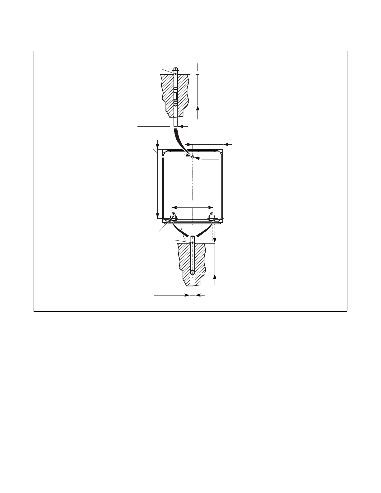
ANCHORING BOLT
(SUPPLIED WITH
THE MACHINE)
VIEW FROM ABOVE
REAR SIDE
FRONT SIDE
630 / 24.80
18 / 0.71
∅ 18/0.71
min. 140/5.51
100 / 3.94
∅ 16 - 18 /
0.63 - 0.71
THREADED ROD
M14 x 120 AND
CHEMICAL FILLING
ARE NOT SUPPLIED
WITH THE MACHINE
∅ 16 / 0.63
890 / 35.04
1216 / 47.87
141 / 5.55
.
Installation
CFD979N
Figure 12
D1590ENR2
© Copyright, Alliance Laundry Systems LLC – DO NOT COPY or TRANSMIT
29
Page 32
Installation
min. 140/5.51
REAR SIDE
FRONT SIDE
VIEW FROM ABOVE
Ø18/0.7
ANCHORING BOLT
(NOT SUPPLIED
WITH THE MACHINE,
ON REQUEST)
ANCHORING
BOLT (NOT
SUPPLIED
WITH THE
MACHINE,
ON REQUEST)
B
D
ACC
Ø18/0.7
min. 140/5.51
Machine Anchoring - 180/800, 230/1000 and 275/1200
Models With Tilt Option
Figure 13
Machine 180/800 230/1000 275/1200
A
1482/58.35 1768/69.61
CFD974N
B
C
D
30
© Copyright, Alliance Laundry Systems LLC – DO NOT COPY or TRANSMIT
1575/62.01 1430/56.30
41.5/1.63 41.5/1.63
45.5/1.79 101.5/4
Table 13
D1590ENR2
Page 33

Installation
Connections
Water Connection
The washers are equipped with 3/4 in., 1 in. or
1-1/2 in. BSP (British Standard Pipe Thread) hot and
cold water inlet valves, indicated by a sticker next to
the inlet. For connection locations, refer to Figure 2
and Figure 3.
NOTE: Water inlet hose with the notches should be
connected to the water supply faucet, while the side
of the water inlet hose without notches should be
connected to the water inlet valves.
Use the water inlet hoses that accompany the washer
as they are properly adapted to the water valves and
appliance. NEVER use a rigid connection to the water
supply.
If using 3/4 in. inlet hoses, there are 2 kinds of water
inlet hoses: water inlet hoses with BSP threaded nuts
at both sides or BSP threaded nut on one end and a
NPT nut on the other end. If a NPT nut is present, it is
marked with a groove.
The 1 in. or 1-1/2 in. inlet hoses have BSP threaded
nuts on both sides. To connect them to a NPT
installation, an adapter is available. For best operation
of the washer, it is necessary to keep the water
pressure within the limits stated in Tabl e 1 . Water
pressure that is below minimum requirements can
lengthen the wash cycle and/or not allow proper
function of the washer.
It is also necessary to connect ALL available water
inlets to a water supply. If a hard water supply is not
present, connect it with soft cold water. If no hot water
is present, contact your dealer for the proper required
action.
NOTE: When connecting inlet hoses, be sure hose
connections are not cross-threaded on the
connection devices.
3. Tighten the hoses securely. DO NOT over tighten
as this will damage threads on the device(s).
The water hardness can have an influence on the wash
results. The soap supplier can help you with making
the right decisions concerning hard water, soft water,
washing programs, type of soap and other related
items to give the best wash results.
Hot Water
IMPORTANT: Temperature in Washing Tub
The electronic controller uses the temperature sensor
in the tub to control the temperature of the washing
bath. There are a lot of things that have influence on
the temperature measurement. Therefore the
temperature control of the washing bath is not very
precise.
In principle, the manufacturer strives that the real
temperature inside the washer is never higher than the
programmed temperature so that textile linen will not
be damaged because of too high of temperature. If for
certain applications a very precise washing bath
temperature is needed, appropriate measures must be
taken, see Programming Manual.
The manufacturer will refuse any responsibility for all
consequences because of inaccurate temperature
inside the washing machine tub.
The hot water supply needs to be large enough to
provide the required hot water for the installed
washers. For good wash results we advise a hot water
supply that is set between 158-176°F/70-80°C.
To I ns tal l
1. Flush the water system in order to remove any
particles that may be in the water system.
2. Install the filter device on the washer, normally
delivered with the machine. Connect the filter
device to the inlet water hose with appropriate
seal washer where necessary.
D1590ENR2
© Copyright, Alliance Laundry Systems LLC – DO NOT COPY or TRANSMIT
31
Page 34
Installation
Install a steam supply disconnecting
device in the vicinity of each washer.
Always disconnect the steam supply
before any service or intervention, giving
sufficient time to cool down the parts to
avoid injuries.
W841
WARNING
It is necessary to insert a filter with
permeability up to 300 micrometers in
front of the steam valve. Dirt and debris
larger than 300 micrometers might damage
the steam valve and cause it to leak.
W842
WARNING
Water Consumption
The water consumption depends on the programmed
values in the controller. These default values can be
found in the Programming Manual. For a pre-wash
and wash the low water level (LL) is used. The high
water level (HL) is used for rinsing. The programmed
units correspond to an average amount of water. You
can calculate the total water consumption in one
washing program by counting up the amount of water
by each washing step. Be aware of the fact that these
are only indicative values. The values received from
this calculation are only an estimation of the real water
consumption. The deviation depends on many
circumstances. In the wash cycle, for example, there
will be a mix of warm water and cold water. The mix
of the water depends on the temperature of both. The
total amount of water consumed depends also on the
loading, type of linen and the drum rotation.
Water Drain Connection
By default 75/335, 90/400 and 125/520 washers are
equipped with two drain outlets with an outer
dimension of 75 mm (3 in.), while 180/800, 230/1000
and 275/1200 washers are equipped with two drain
outlets with an outer diameter of 103 mm (4 in.). The
drain outlets are situated on the rear of the machine.
The drain has to be connected to the waste channel or
pipeline. Seal the connecting point of the drain throat
and flexible hose with silicon cement. Secure the
elbow or the hose with a clamp. Cover the waste sump
with a proper cover.
Steam Connection
For dimensions of steam connection information, see
Tab l e 1 . Use an inlet steam pressure hose only, adapted
to the steam valve with appropriate seal that is suitable
for the applied working pressure.
IMPORTANT: Take care while installing and
connecting steam supply to prevent accidental
contact. Due to the high temperatures, direct
injuries will occur.
IMPORTANT: The waste channel must be located
lower than the drain outlets because the water
discharges from the machines by gravity. Do not
reduce the diameter of the machine drain pipes.
The main waste channel or pipeline must have such a
capacity that it can take away the drained water from
all connected machines at the same time. Ask a
corresponding expert (construction technician) to
design a sufficiently dimensioned waste pipeline for
your washing machines. The correctly designed
pipeline is fitted with the main ventilating pipeline
(air supply) and possibly an auxiliary ventilating
pipeline. This will prevent deceleration of the flow and
creation of a high vacuum or overpressure inside the
pipeline, causing a breach of the water level in odor
closures.
32
© Copyright, Alliance Laundry Systems LLC – DO NOT COPY or TRANSMIT
D1590ENR2
Page 35
Installation
Vapors escape from the machine through
the air vent opening! Do not cover.
W843
WARNING
Venting
The vent air opening is part of the back flow
prevention water system. It also makes sure that the
tub can not be pressurized by water intake and water
vapor. It also allows proper measuring of the water
level.
For the safety of everyone make sure that unauthorized
persons cannot reach the back side of the machine.
Although it is not advised, you can connect the
machine venting pipe to the laundry central duct for
exhausting the vapor out of the building. The external
diameter of the ventilating opening is 60 mm (2.4 in.)
for 75/335, 90/400 and 125/520 models and 40 mm
(1.5 in.) for 180/800, 230/1000 and 275/1200 models.
Electrical specifications
Voltage Designation Hot/Cold Water Fill and Steam Heat
Model
*Y90
(400)
*Y125
(520)
*Y180
(800)
*Y230
(10X)
*Y275
(12X)
Code Voltage Cycle Phase Wire
Q 200 - 240 50 - 60 3 3 (L1, L2, L3) 20 30 (32) 10 (6)
N 440 - 480 50 - 60 3 3 (L1, L2, L3) 12 15 (16) 14 (2.5)
Q 200 - 240 50 - 60 3 3 (L1, L2, L3) 23 30 (32) 10 (6)
N 440 - 480 50 - 60 3 3 (L1, L2, L3) 14 20 (20) 12 (4)
Q 200 - 240 50 - 60 3 3 (L1, L2, L3) 44 60 (63) 6 (16)
N 440 - 480 50 - 60 3 3 (L1, L2, L3) 26 40 (40) 8 (10)
Q 200 - 240 50 - 60 3 3 (L1, L2, L3) 60 80 (80) 4 (25)
N 440 - 480 50 - 60 3 3 (L1, L2, L3) 35 50 (63) 8 (10)
Q 200 - 240 50 - 60 3 3 (L1, L2, L3) 74 100 (100) 3 (25)
N 440 - 480 50 - 60 3 3 (L1, L2, L3) 42 60 (63) 6 (16)
Table 14
For placing of connection points see Figure 2,
Figure 3, Figure 6 and Figure 7. The piping material
must withstand a temperature of 80°C/176°F and
generated machine vibrations. The central duct for
multiple venting must be dimensioned for the total
cross section of venting pipes of all machines. Make
sure that this installation can not create any injuries.
Electrical Connection
The machine has been designed for connecting to the
power network according the specification of your
order. Refer to Table 14 for electrical specifications.
Before connection check the voltage values and the
frequency stated in the machine label (see Figure 2
and Figure 6.) to see if they correspond to your power
network. An individual branch circuit needs to be used
for each machine. The connection is described in
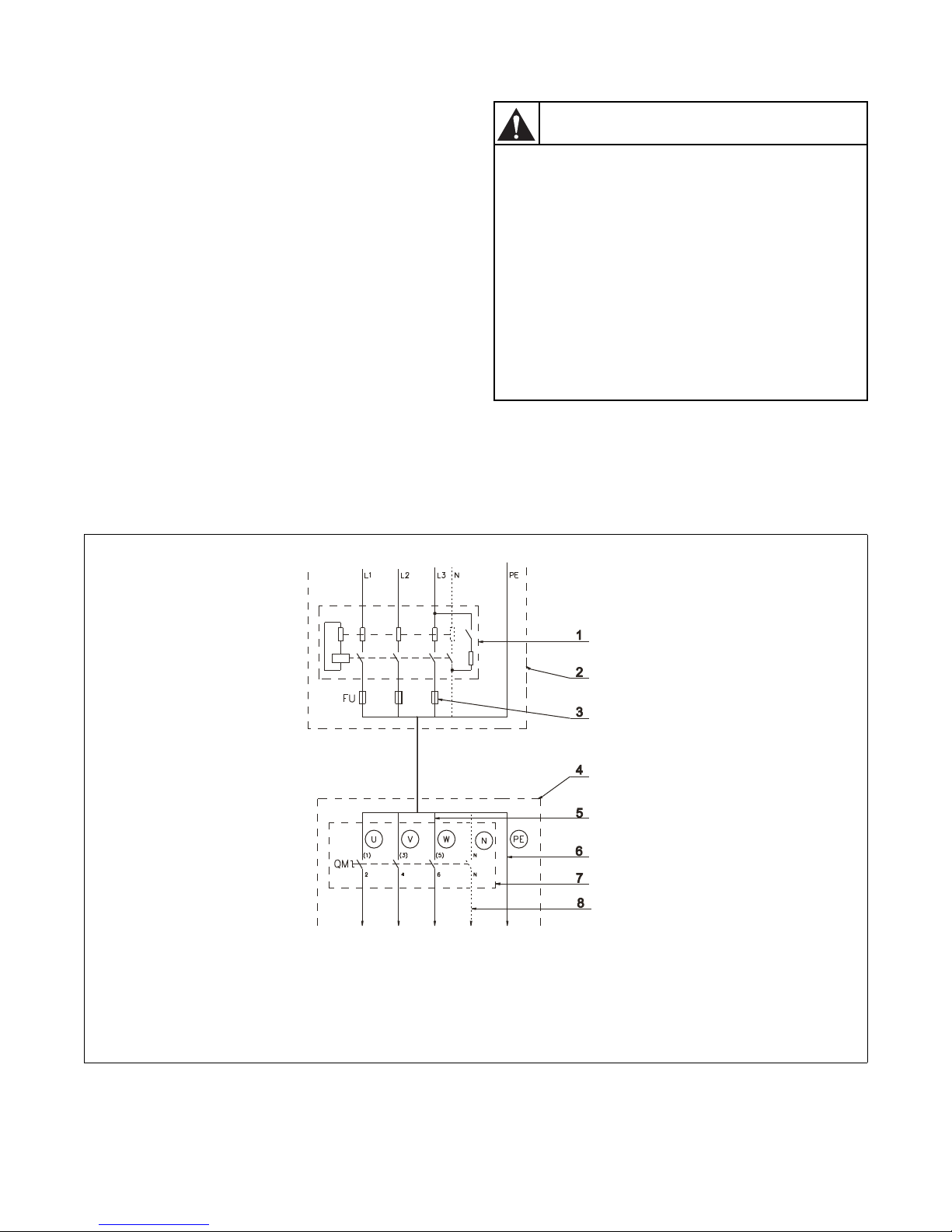
Figure 14. For electrical protection, a residual current
device (RCD) and a circuit breaker must be installed in
the electrical installation of the building (laundry
switchboard). For correct selection see below in
Residual Current Device (RCD).
Full
Load
Amps
Circuit
Breaker
CSA
CSA
AWG
(mm
²)
D1590ENR2
© Copyright, Alliance Laundry Systems LLC – DO NOT COPY or TRANSMIT
33
Page 36
Installation
Grounding: In event of malfunction,
breakdown or leakage of current,
grounding will reduce the risk of electrical
shock and serve as a protecting device, by
providing a path of least resistance of
electrical current. Therefore, it is very
important and the responsibility of the
installer to assure the washer is
adequately grounded at the point of
installation taking into consideration the
national and local conditions and
requirements.
W844
WARNING
IMPORTANT:
• If the machine is not equipped with a main
switch then supply disconnecting devices need
to be provided in the installation for all
electrical supplies connected to the machine,
in accordance with EN 60204-1 standard,
point 5.3.
• Make sure the supply voltage is always within
the limits specified in Tab le 1 in all
circumstances. When you have long distances
in the electrical installation, it may be
necessary to use bigger cables to reduce the
voltage drop.
• When the machine is connected near a large
capacity power supply transformer (500k VA
or more, wiring length shorter than 10 m) or
there is a power capacitor switch-over, a
power supply improving reactor must be
installed. If you do not install this, the inverter
may get damaged. Contact your sales office
for more info.
1 Residual current device (RCD) 5 Phase conductors
2 Laundry electrical switchboard 6 Protective conductor
3 Supply protection device 7 Main switch inlet terminal switchboard
4 Washing machine 8 Neutral conductor
34
© Copyright, Alliance Laundry Systems LLC – DO NOT COPY or TRANSMIT
CFD826N
Figure 14
D1590ENR2
Page 37

Installation
Residual Current Device (RCD)
In some countries an RCD is also known as an “earth
leakage trip”, “Ground Fault Circuit Interrupter”
(GFCI), an “Appliance Leakage Current Interrupter”
(ALCI) or “earth (ground) leakage current breaker”.
Specifications:
• Tripping current: 100mA (if locally not available/
allowed use a 30mA trip current, preferably
selective type with small time delay set)
• Install a maximum of 2 machines on each RCD
(for 30mA, only 1 machine)
• Type B. There are components inside the
machine which make use of DC-voltages and
therefor a “type B” RCD is necessary. For
information only: Type B is better performance
than type A, and type A is better than type AC.
When locally allowed, there must always be an RCD
installed. In some power network earthing systems (IT,
TN-C,…), an RCD might not be allowed (see also IEC
60364).
The machine control circuits are mostly supplied by a
separating transformer. Therefore the RCD may not
detect faults in the control circuits (but the fuse(s) of
the separating transformer will).
Supply Protection Device
A supply protection device basically protects the
machine and wiring against overloads and short
circuits. As a supply protection device, you can use
either (glow-wire) fuses or (automatic) circuit
breakers. See Tab le 1 5 for the rating of the nominal
current and other specifications of the supply
protection device. In this table it is specified that the
protection must be the “slow” type - for circuit
breakers which means curve D. Although not
recommended, if for some reason you can not use a
slow type, select the protection device with 1 step
higher nominal current rating to avoid disconnecting
during start-up.
Supply Cable
The supply cable is not delivered with the machine.
Specifications:
• The conductors must have copper cores.
• Stranded conductors are strongly recommended
(flexible wiring) to avoid conductor breaking
because of vibration.
• The cross section depends on the used supply
protection device. See Table 15 for the minimal
cross section.
• The cable should be as short as possible, directly
from the supply protection device to the machine
without branching off.
• No plug or extension cords: The machine is
intended to be permanently connected to the
electrical network.
Connection:
1. Insert the cable through the hole in the rear panel.
Ensure a strain relief (turnbuckle) is used so that
the supply cable can not move.
2. Strip the conductor ends according to Figure 16.
3. The protective conductor must be longer so that
when the cable is pulled out accidentally, this
conductor is disconnected last.
4. With stranded conductors, use “wire end tubes”
with an insulated sleeve (6) for L1/U, (L2/V),
(L3/W), (N) conductors. Make sure there can not
be accidental contact, since the supply cable
stays under voltage even when the main switch is
off.
5. Crimp a ring terminal (eyelet) to the protection
conductor for a good connection to the PE
terminal.
6. Connect the supply cable conductors to the
terminals (main switch (1)) marked with L1/U,
(L2/V), (L3/W), (N), and the terminal (copper
screw) marked with PE, see Figure 17.
D1590ENR2
© Copyright, Alliance Laundry Systems LLC – DO NOT COPY or TRANSMIT
7. Provide a sag in the cable, in front of the cable
strain relief. This will avoid ingress of condensed
water into the machine, see Figure 17.
35
Page 38
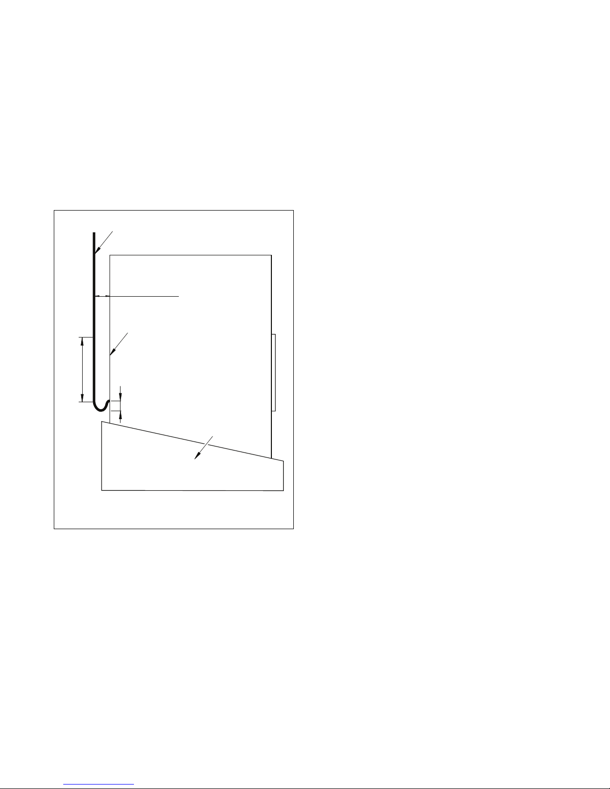
Installation
3
1000 mm / 39.37 in.1000 mm / 39.37 in.
50 - 150 mm / 1.97 - 5.91 in.50 - 150 mm / 1.97 - 5.91 in.
300 mm / 11.81 in.300 mm / 11.81 in.
CFD951N
2
1
MACHINE WITH TILTING
Supply Cable Positioning – Tilt Models Only
The selected power supply cable, Figure 15 pos. 1,
needs to come from above and vertical directed
downwards in 1ine with the supply cable entry.
The cable needs to be on 300 mm (11.81 in.) from the
back of the machine when the machine is not tilted.
Just before entry, a sag of min 50 mm (1.97 in.) and
max 150 mm (5.91 in.) must be provided.
From the point of entry, up 1000 mm (39.37 in.) high,
no fixation of the supply cable is allowed.
Figure 15
36
© Copyright, Alliance Laundry Systems LLC – DO NOT COPY or TRANSMIT
CFD951N
D1590ENR2
Page 39
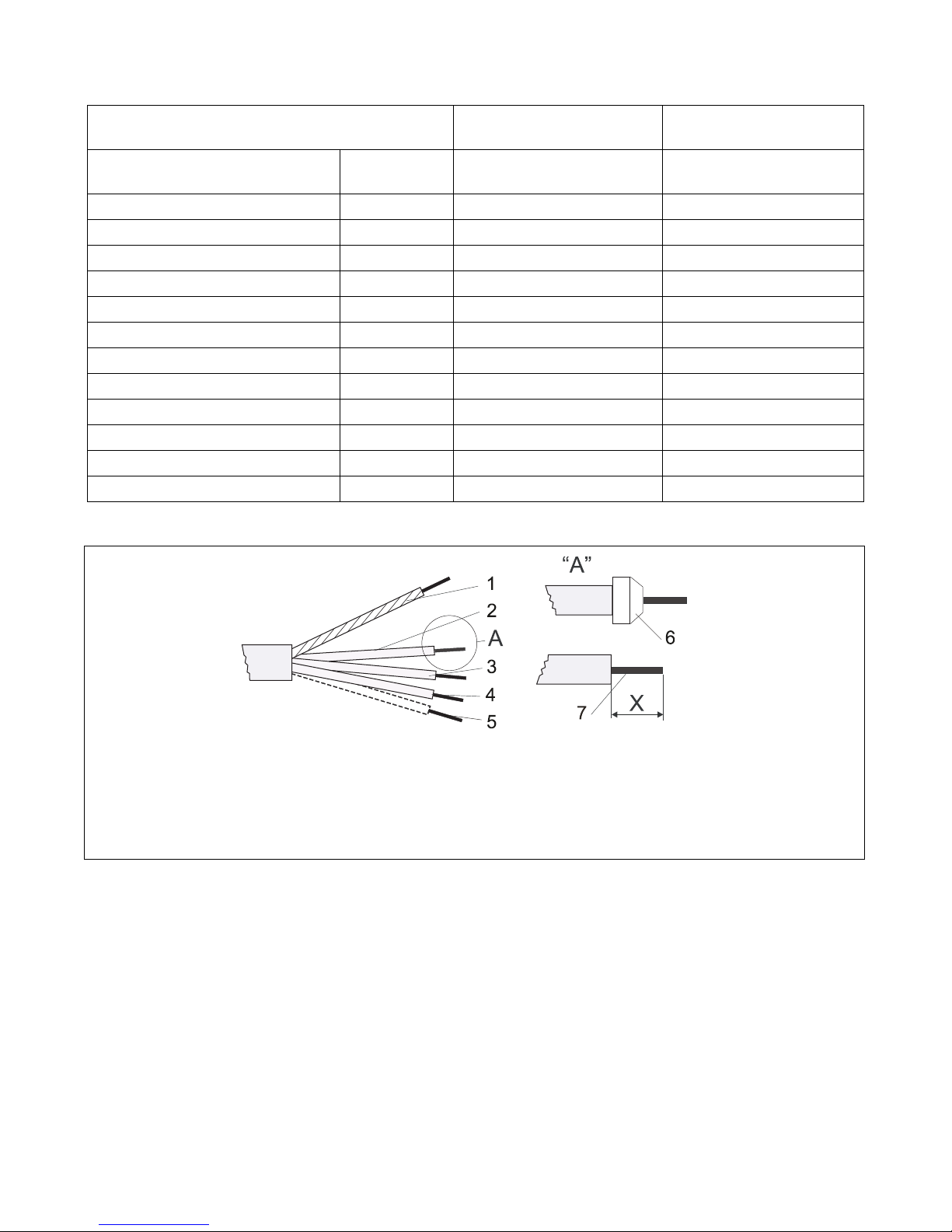
Installation
Power supply protection device
nominal current (US)
Automatic circuit breakers
A
16 (15) 10 (10) 1.5 (AWG 15) 1.5 (AWG 15)
20 (20) 16 (15) 2.5 (AWG 13) 2.5 (AWG 13)
25 (-) 20 (20) 4 (AWG 11) 4 (AWG 11)
40 (40) 32 (30) 6 (AWG 9) 6 (AWG 9)
63 (-) 50 (50) 10 (AWG 7) 10 (AWG 7)
80 63 16 (AWG 5) 16 (AWG 5)
100 80 25 (AWG 3) 16 (AWG 5)
125 100 35 (AWG 2) 25 (AWG 3)
160 125 50 35 (AWG 2)
200 160 70 50
250 200 95 70
300 250 120 95
Fuses
A
Min phase conductor
section in mm² (AWG)
Table 15
Min Protection conductor
section in mm² (AWG)
1 Protection conductor 5 Neutral conductor
2 Phase conductor 6 Molded tube
3 Phase conductor 7 The stripped length of conductors
4 Phase conductor
Figure 16
D1590ENR2
© Copyright, Alliance Laundry Systems LLC – DO NOT COPY or TRANSMIT
CFD827N
37
Page 40
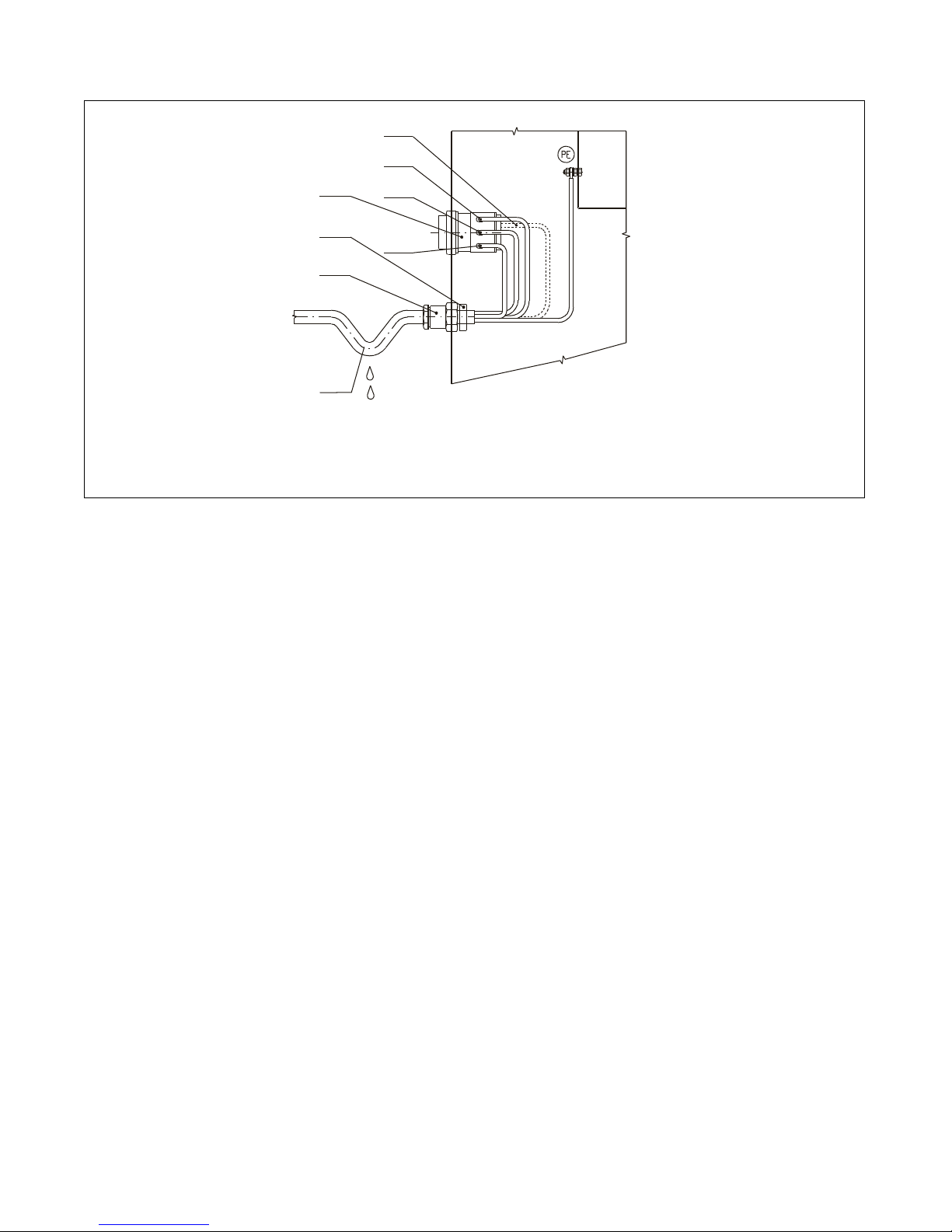
Installation
U,L1
W,L3
V,L2
N
1
3
2
4
1 Main Switch 3 2 Turnbuckle 4 Sag of inlet cable
CFD828N
Figure 17
Washer Protective Earth Connection and
Equipotential Bonding
Independent of the supply cable, the washer must be
connected to the laundry protective earth system with
a separate conductor. The protection conductor,
enabling this connection, is not included with the
washer. If there are other washers/appliances with
exposed conductive parts, which can be touched
simultaneously, make sure to make equipotential
bonding between all these appliances.
The external protective terminal for this purpose is
located on the rear panel of the machine frame. The
minimum protection conductor’s cross section
depends on the supply cable cross section and can be
found in Tabl e 1 5 . However, for the protection
purposes with the supply cable section of min. 4 mm²,
we recommend to select a larger conductor section, i.e.
6 mm².
38
© Copyright, Alliance Laundry Systems LLC – DO NOT COPY or TRANSMIT
D1590ENR2
Page 41
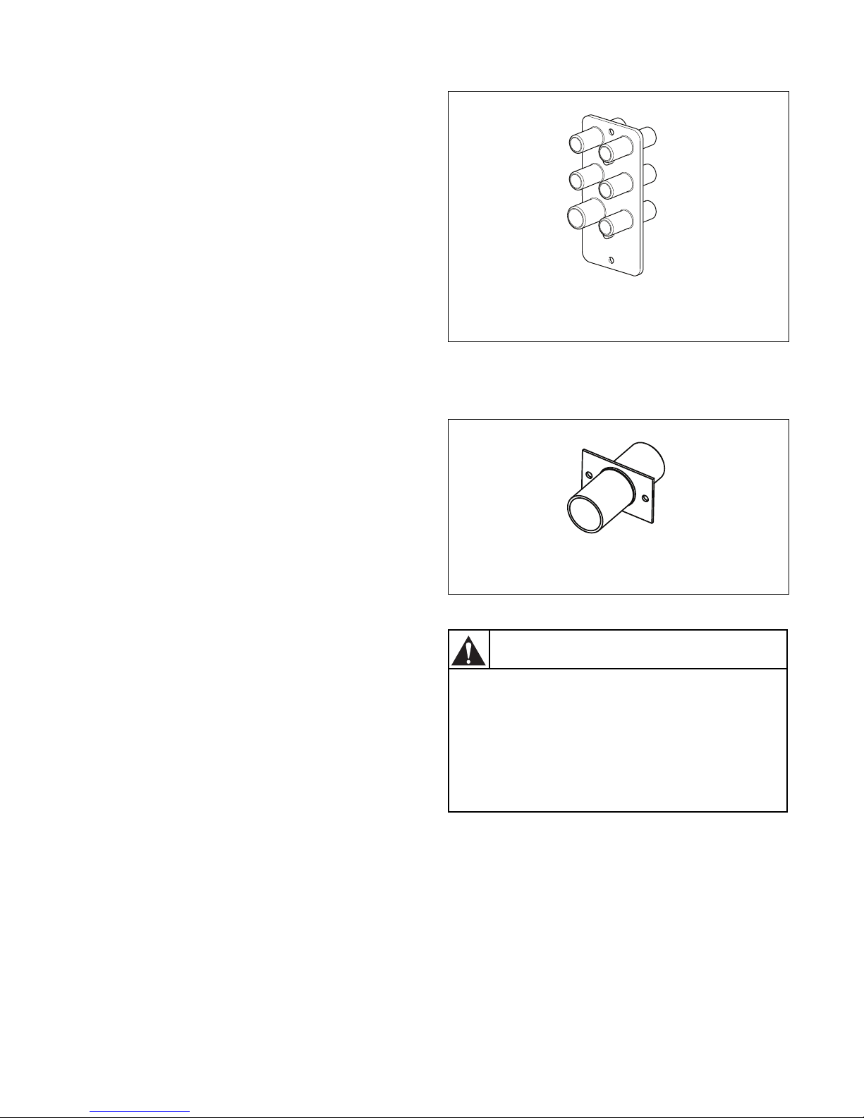
Liquid Soap Connection
Hose Connections Models 40/100, 55/125, 75/335, 900/400 and 125/520
CFD831N
Hose Connection Models 180/800, 230/1000 and 275/1200
Check that the hose connections are tight
(check the clamps)! Any leakage of
chemicals may cause serious bodily
injuries as well as serious damage to the
washer. If one of the nipples are open,
close and secure the opening with an
appropriate cover.
W845
WARNING
Connection point for soap supply. See Figure 2,
Figure 3, Figure 6 and Figure 7.
NOTE: Always use liquid soap pumps that have a
flow rate high enough to bring the requested
quantity into the washer in less than 30 seconds.
IMPORTANT: Start pumping immediately after
the water valves are open. The incoming water
dilutes the liquid soap and brings it into the tub
assembly.
CAUTION: Secure the location of the wiring and
hoses in such a way that they can not be pinched,
damaged or rubbed. Only authorized workers,
with a valid qualification, should do the
installation. Before you start to use liquid soap,
check with your liquid soap supplier whether the
liquid soap is harmless and inert to HD-PPE and
PVC material in order to avoid a problem that the
manufacturer is not responsible for.
Installation
CFD965N
CFD965N
Figure 18
Refer to Figure 19 for the 180/800, 230/1000 and
275/1200 liquid soap connection.
For 75/335, 90/400 and 125/520 models, six liquid
soar dispensers are provided. Refer to Figure 18. The
8 mm (.315 in.) connectors should be used for liquid
soap, while the 12 mm (.5 in.) connector should be
used for diluted soap. The connectors must be drilled
out and opened before the liquid soap hoses are
connected to them.
NOTE: Only open the connectors that will have an
attached hose.
Refer to Figure 19 for the 180/800, 230/1000 and
275/1200 liquid soap connection details.
CFD831N
Figure 19
D1590ENR2
© Copyright, Alliance Laundry Systems LLC – DO NOT COPY or TRANSMIT
39
Page 42
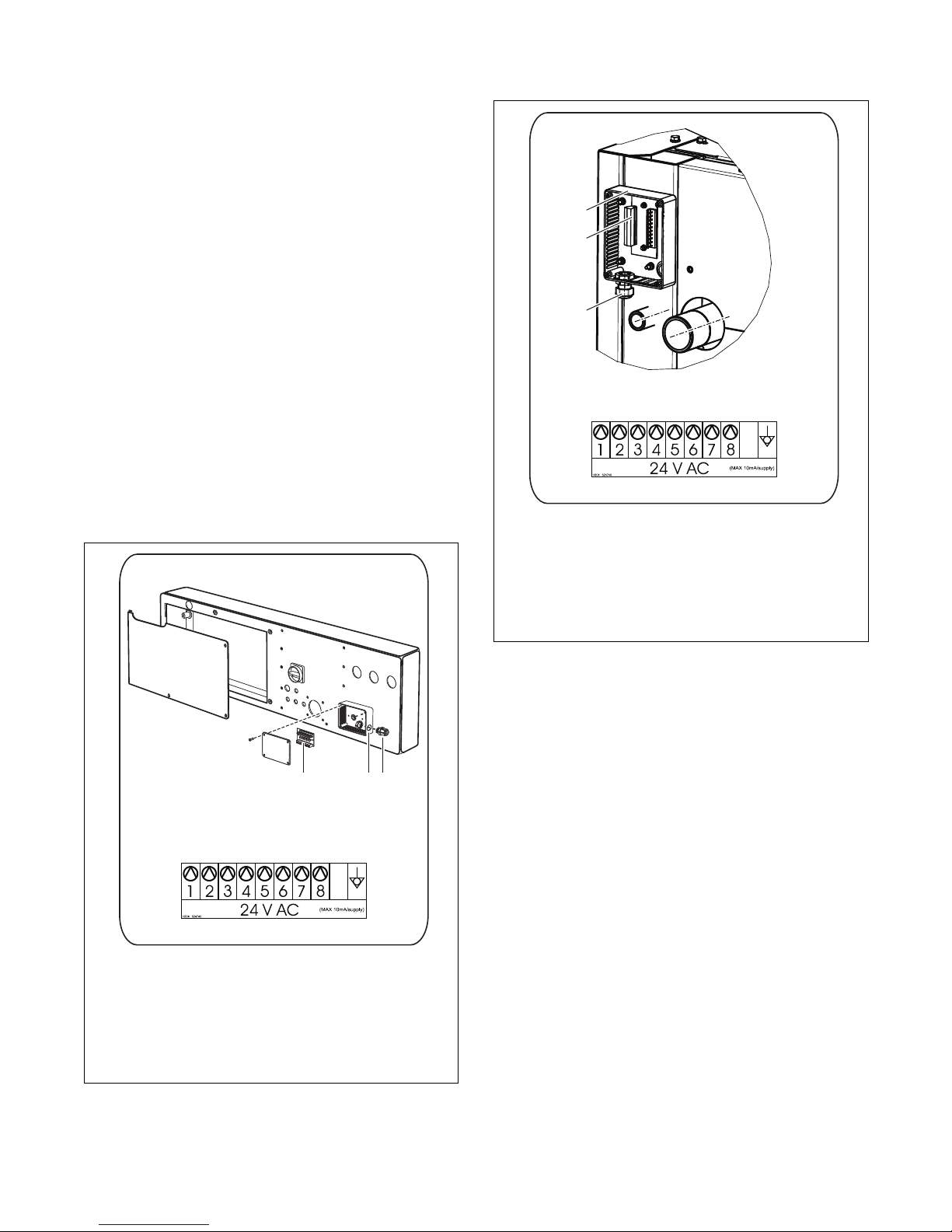
Installation
213
2
1
3
Electrical Connection
The power supply of the liquid soap pump system has
to be connected to an external electrical source. Only
authorized workers with a valid qualification must
execute the electrical connection on the machine
according to the valid local standards. The correct
connection way can be found on the wiring diagram
that is located inside the cabinet in a plastic bag. Do
not connect the liquid soap pump system in the
washer.
Electronic Controller with Blue PCB and
Graphical Display
For electric connection of supply control signals, a
plastic box is available on the back side of the machine
with a terminal box that shows an LED signal when
each respective pump is activated. Under the terminal
box, there is a label for electric connection. Detailed
signal connections can also be found on the electric
scheme of the machine. Refer to Figure 20 for 75/335,
90/400 and 125/520 models and to Figure 21 for 180/
800, 230/1000 and 275/1200 models.
CFD952N
Electrical Connection Label-
Models 180/800, 230/1000 and 275/1200
1 Plastic Box
2 Ter mi n a l B o x
3 Plastic Cable Bushing
Figure 21
Signals for supply pumps control are 24 VAC.
Maximum current for control circuits of pumps must
be limited to 10mA. Lead the pump control signal
cable through the plastic cable bushing. After
connection of conductors to the respective positions of
the connector “P” (screw clamps), fix up the cable by
tightening the cable bushing to prevent it from
disconnecting and close the box with the cover. For
details about liquid soap supply system programming,
see Programming Manual.
1 Plastic Box
2 Terminal Box
3 Plastic Cable Bushing
Electrical Connection Label-
Models 75/335, 90/400 and 125/520
Figure 20
CFD966N
40
© Copyright, Alliance Laundry Systems LLC – DO NOT COPY or TRANSMIT
D1590ENR2
Page 43
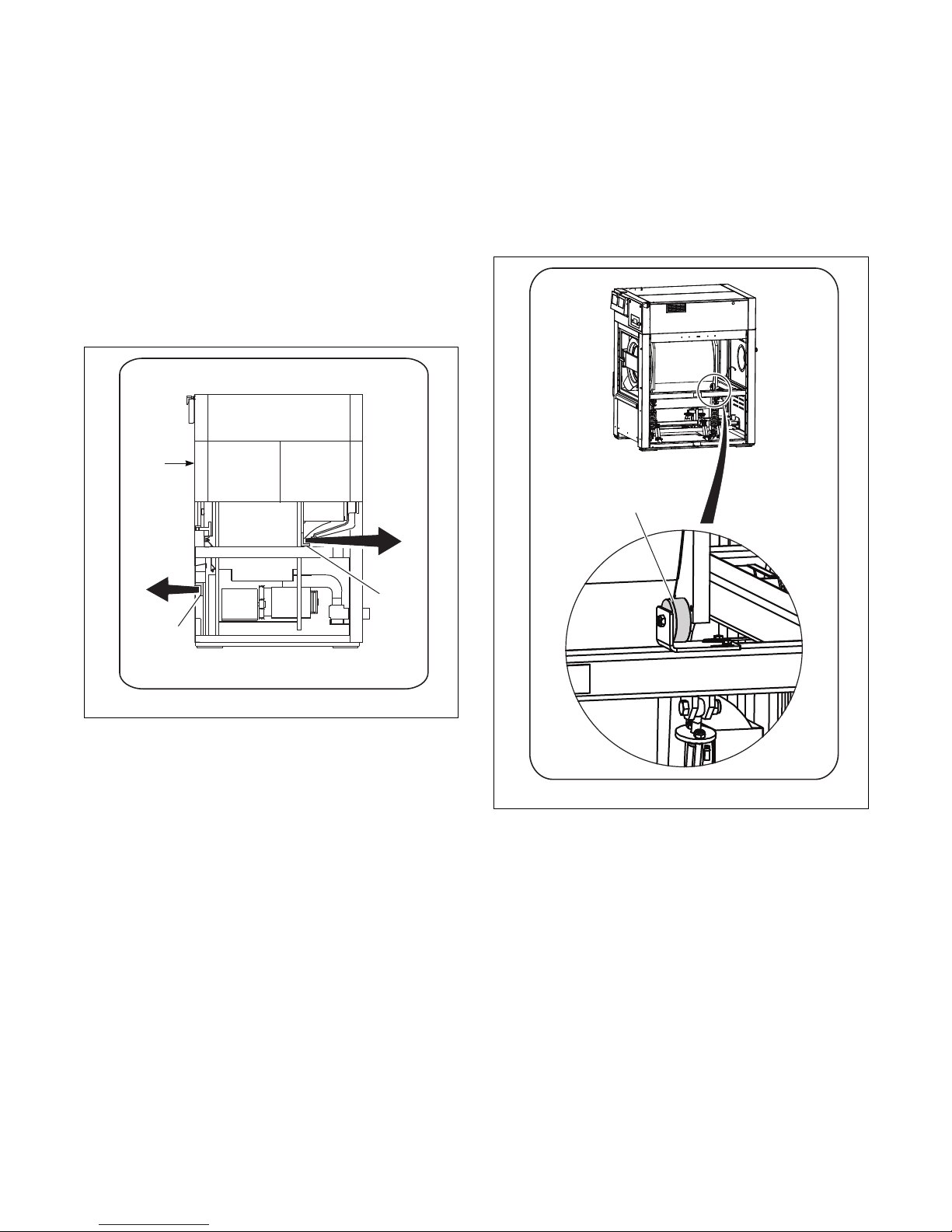
Installation
1
2
FRONT
SIDE
BACKSTOP
Putting the Machine into Service
Models 75/335, 90/400 and 125/520
Before you put the machine into operation, remove the
three striking color transport braces securing the
vibrating machine components during transport. Refer
to Figure 22. One brace (pos.1) is located in the front
part of the machine, accessible after removal of the
front lower cover. The two braces (pos. 2) are placed
in the rear machine part, accessible after removal of
the case cover. After removal of the braces, mount the
covers back to their places.
Models 90/400 and 125/520
with Tilt Option
Once the transport braces are removed, place two
backstops supplied with the machine in their places.
Refer to Figure 23. These backstops secure the
machine when it is being tilted. When the braces are
removed and backstops attached, put the guards back.
CFD967N
Figure 22
CFD968N
Figure 23
D1590ENR2
© Copyright, Alliance Laundry Systems LLC – DO NOT COPY or TRANSMIT
41
Page 44
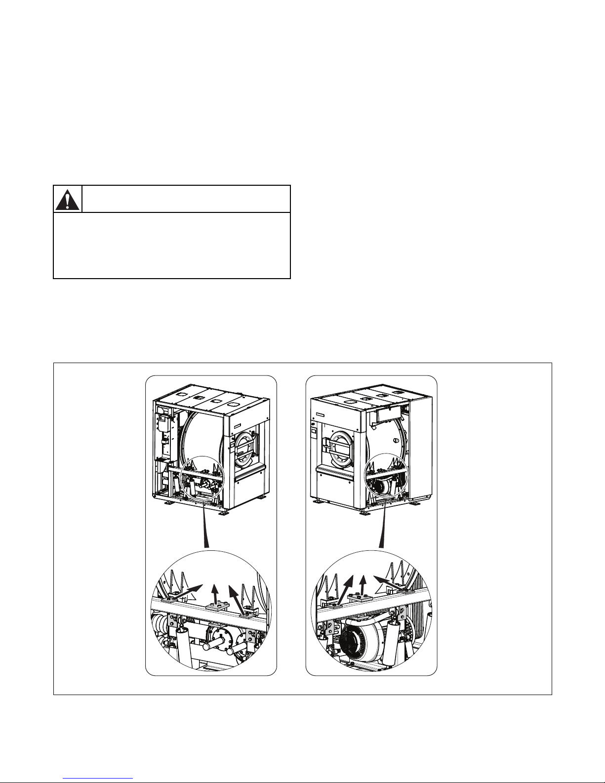
Installation
The transport braces must be removed
prior to putting your machine into service,
otherwise your washing machine can be
seriously damaged!
W846
WARNING
Models 180/800, 230/1000 and 275/1200
Before you put the machine into operation, remove the
six striking color transport braces securing the
vibrating machine components during transport. The
three braces are placed on the left side of the machine
and three braces are placed on the right side of the
machine, accessible after removal of the side covers.
After removal of the braces, mount the covers back to
their places. Refer to Figure 24.
Checking Before Putting into Service
1. Check that the transport braces are removed.
2. Make sure the cabinet protective foil is removed.
3. Check if the waste sump is ready for water
drainage.
4. Check the protective connection (earth
connection) - “PE” or “PEN”.
5. Carefully read the operation manual before the
machine start and following the instructions
stated.
6. Check the drum rotation direction during
extracting. For 75/335, 90/400 and 125/520
models, the drum rotation should be counterclockwise during extraction while facing the
front of the machine. For 180/800, 230/1000
and 275/1200 models, the drum rotation should
be clockwise during extraction while facing the
front of the machine.
7. Check that the vibration switch function and the
emergency function is operating properly during
extracting.
42
© Copyright, Alliance Laundry Systems LLC – DO NOT COPY or TRANSMIT
CFD953N
Figure 24
D1590ENR2
Page 45
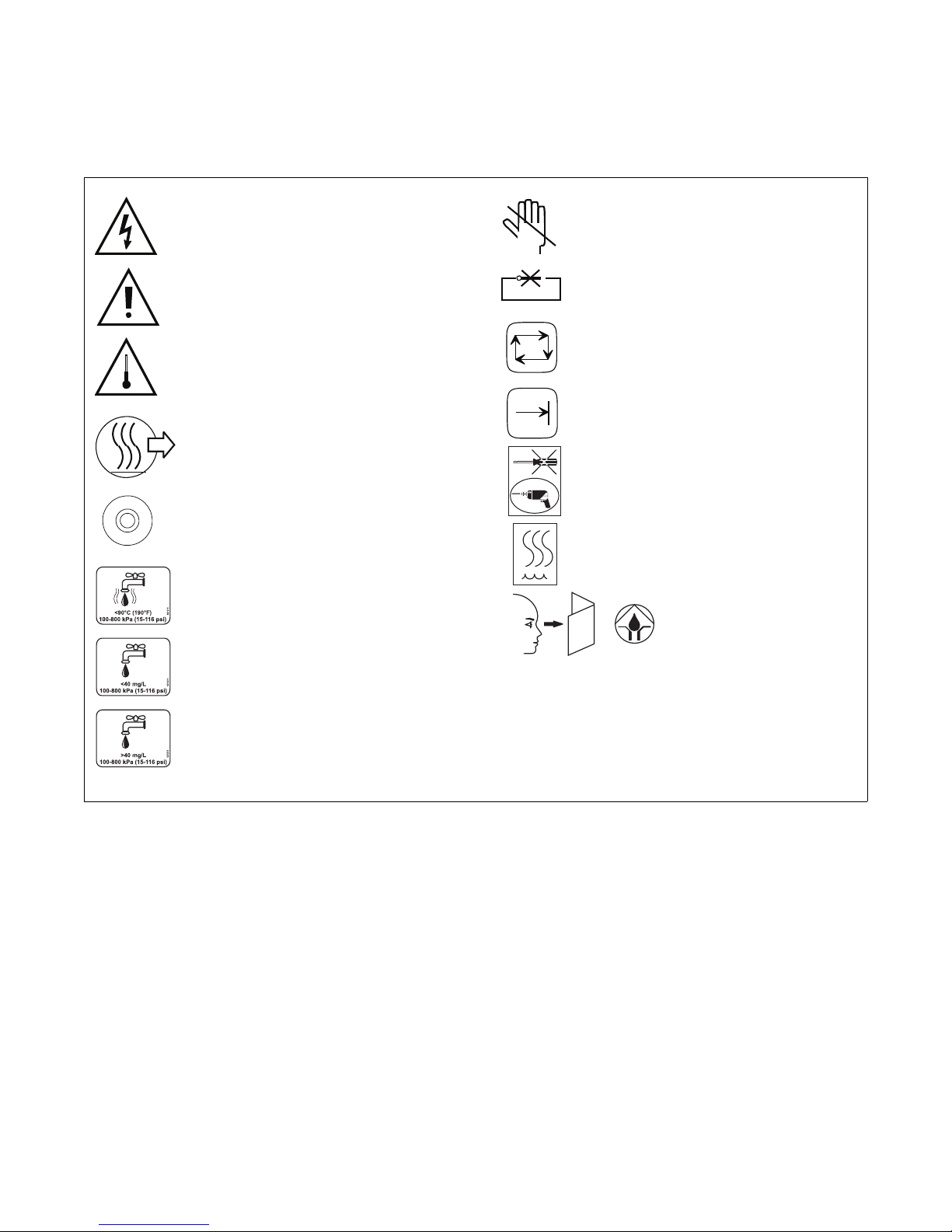
Symbols on the Machine
i
Caution, dangerous electrical tension,
electrical devices
Caution, other danger, read and
follow written instructions
Caution - Increased temperature
The machine hot air outlet
In case of emergency press the
emergency button to stop the machine
Warm water inlet
(red label)
Soft cold water inlet
(light blue label)
Hard cold water inlet
(dark blue label)
Do not put your hands on the marked
area
Do not close or cover
Machine in operation
The machine is switched over to
programming regime
The holes to be drilled not punched
Steam
Lubrication point
Operation
Figure 25
CFD833N
D1590ENR2
© Copyright, Alliance Laundry Systems LLC – DO NOT COPY or TRANSMIT
43
Page 46
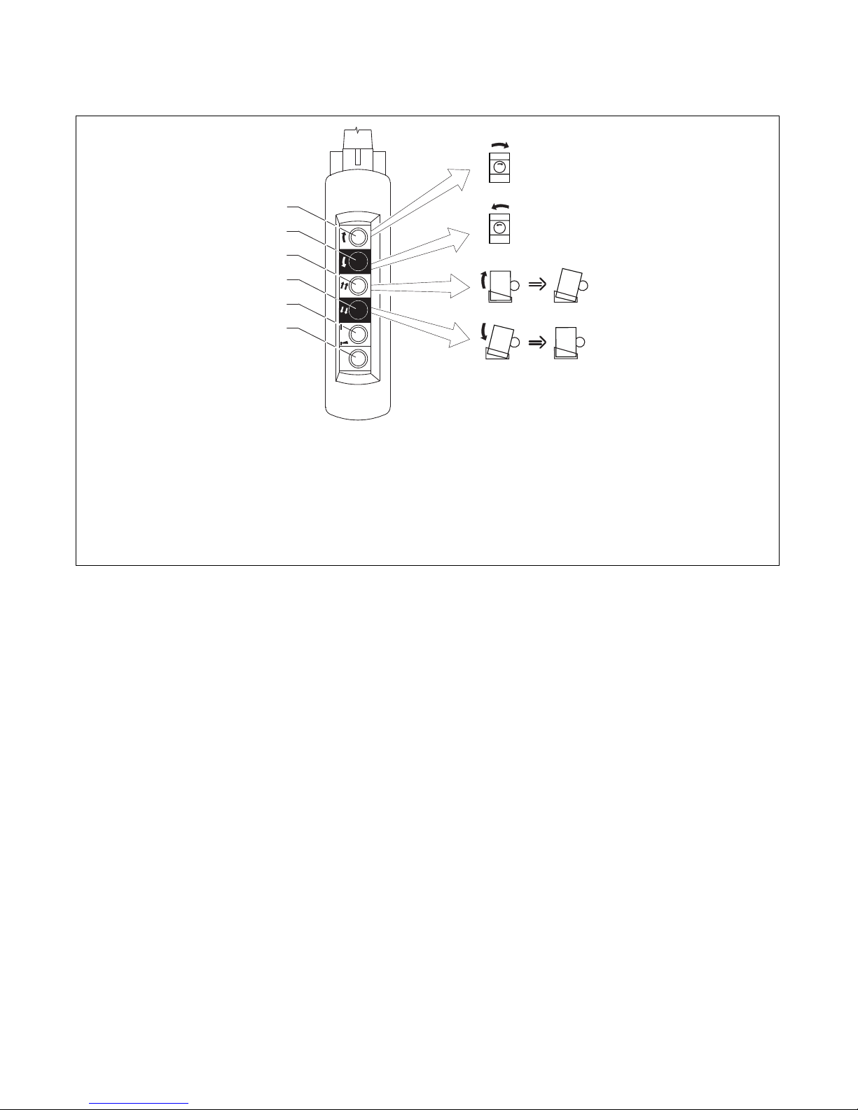
Operation
1
5
6
4
2
3
Hanging Control (Washers with Tilting System)
1 Button for drum rotating, direction of rotating is
clockwise from the front view.
2 Button for drum rotating, direction of rotating is
counter clockwise from front view.
3 Button for tilting, direction of tilting is forward to
unload.
CFD944N
4 Button for tilting, direction of tilting is backward
to basic position.
5 Button for permission of washer tilting - two-
hand control.
6 Button for permission of drum rotation - two-
hand control.
Figure 26
44
© Copyright, Alliance Laundry Systems LLC – DO NOT COPY or TRANSMIT
D1590ENR2
Page 47
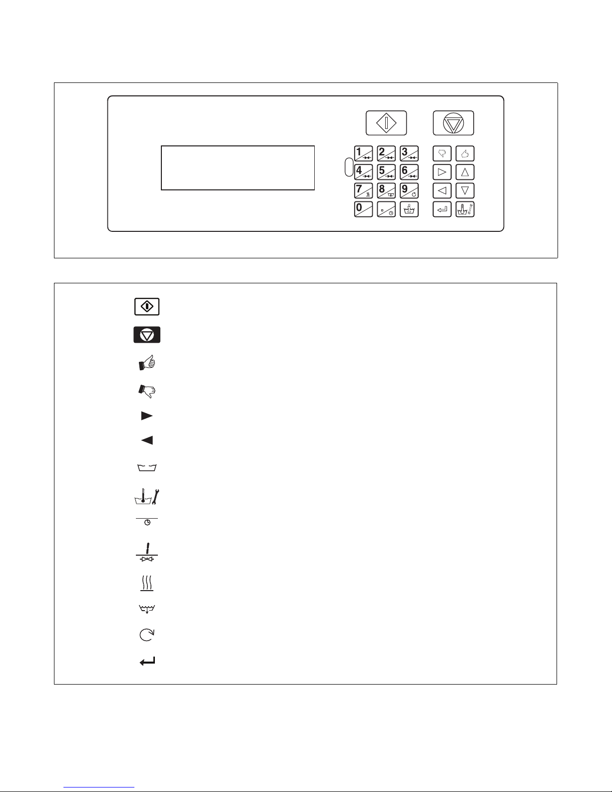
Micro Microprocessor
i
,
START (advancing program)
STOP (interrupting program)
YES SELECTION
NO SELECTION
INCREASING SEQUENCE TIME
DECREASING SEQUENCE TIME
INFO (overview available wash programs and wash sequence functions)
SERVIS (shows actual water temperature and level, number of fulfilled
cycles and actual states
ACTIVATES THE TIME DELAY FUNCTION (delay time will be started by
pressing start)
OPENING THE INLET VALVES
AC T I VAT E H E AT I NG
OPEN DRAIN VALVE
SPEED ADJUST
ENTER - SELECTION OR CONFIRMATION
Operation
CFD1437R
Figure 27
CFD835N
Figure 28
D1590ENR2
© Copyright, Alliance Laundry Systems LLC – DO NOT COPY or TRANSMIT
45
Page 48
Operation
When using the tilting control to tilt the
machine, always stand on the side of the
machine. Do not stand in front or behind
the moving machine!
W847
WARNING
Never put fingers between the door sealing
and drum to avoid possible injury!
W848
WARNING
Before Washing
Sort the linen according to temperature and
instructions determined by fabric manufacturer. Check
laundry for strange objects like nails, screw, needles,
etc., to prevent washer-extractor or linen damage. Turn
sleeves of shirts, blouses, etc., inside out. To get a
better washing result, mix the bigger and smaller
pieces of linen and put them into the washer
separately.
Opening the Door
Turn the handle down.
For models equipped with the tilt option, open and
secure the door. Refer to Figure 6.
When the door is opened, the tilting function is
enabled. The buttons on the hanging control can now
be used.
NOTE: The tilting function is disabled when the
door is closed.
Closing the Door
Turn the handle up.
Before start up, make sure the door is properly latched.
For models equipped with the tilt option, a program
cannot be selected if the machine is not in the basic
position. If the machine’s door is closed before the
machine reaches the basic position, a warning will be
shown on the control’s display. When the warning is
shown, close the door and move the machine to the
basic position.
Program Selection
Choose one of the available wash programs, best
corresponding to the quality of linen and allowed wash
temperature in the wash load. Selection of the program
determines temperature and time for washing and
rinsing.
Loading the Machine with Linen
Do not overload the washer extractor. Overloading the
machine can lead to a bad wash result. Half washing
loads can obstruct proper functioning.
NOTE: To change factory settings and/or washing
programs and for other settings options - see
Programming Manual.
46
© Copyright, Alliance Laundry Systems LLC – DO NOT COPY or TRANSMIT
D1590ENR2
Page 49
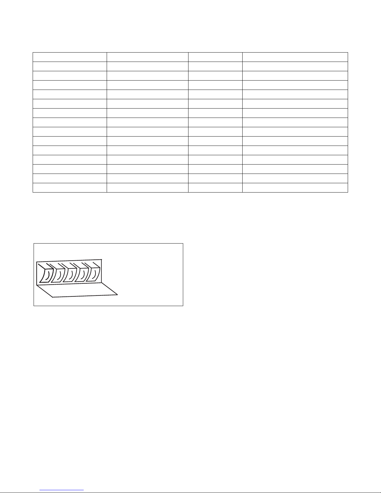
Wash Programs Overview
A B C D E
DISPENSER A: 1ST WASH
DISPENSER B: 2ND WASH
DISPENSER D: LAST RINSE
Wash program 1: Hot wash 90°C/194°F
Wash program 2: Warm wash 60°C/140°F
Wash program 3: Colored wash 40°C/104°F
Wash program 4: Bright colored wash 30°C/86°F
Wash program 5: Woolens 15°C/59°F
Wash program 6: Hot wash 90°C/194°F ECONOMY level
Wash program 7: Warm wash 60°C/140°F ECONOMY level
Wash program 8: Colored wash 40°C/104°F ECONOMY level
Wash program 9: Bright colored wash 30°C/86°F ECONOMY level
Wash program 10: Hot wash 90°C/194°F SUPER ECONOMY level
Wash program 11: Warm wash 60°C/140°F SUPER ECONOMY level
Wash program 12: Colored wash 40°C/104°F SUPER ECONOMY level
Wash program 13: Bright colored wash 30°C/86°F SUPER ECONOMY level
Wash program 14: Extraction low speed
Wash program 15: Extraction high speed
Table 16
Operation
Add Detergent
Fill the soap dispenser at the front or side of the
washer extractor depending on the chosen program.
CFD836N
Figure 29
Add the detergents before the start of the wash cycle.
For washing machines connected to a liquid soap
supply system:
Check if the liquid soap supply system is in operation
and if there is sufficient quantity of liquid soap.
For standard wash programs versus custom made
wash programs:
This explanation is only valid for standard wash
programs. For custom made programs, it is possible
that other dispensers have been selected.
(See Programming Manual.)
NOTE: If it advisable to use only detergents with
“reduced foaming” which can easily be found in
retail shops. The dosage of soap to use is generally
mentioned on the packaging. An overdose of
detergent can lead to poor wash results and “suds”
overflow which can damage the machine.
Make sure that the lid of the soap dispenser is closed
when the machine starts.
D1590ENR2
© Copyright, Alliance Laundry Systems LLC – DO NOT COPY or TRANSMIT
47
Page 50
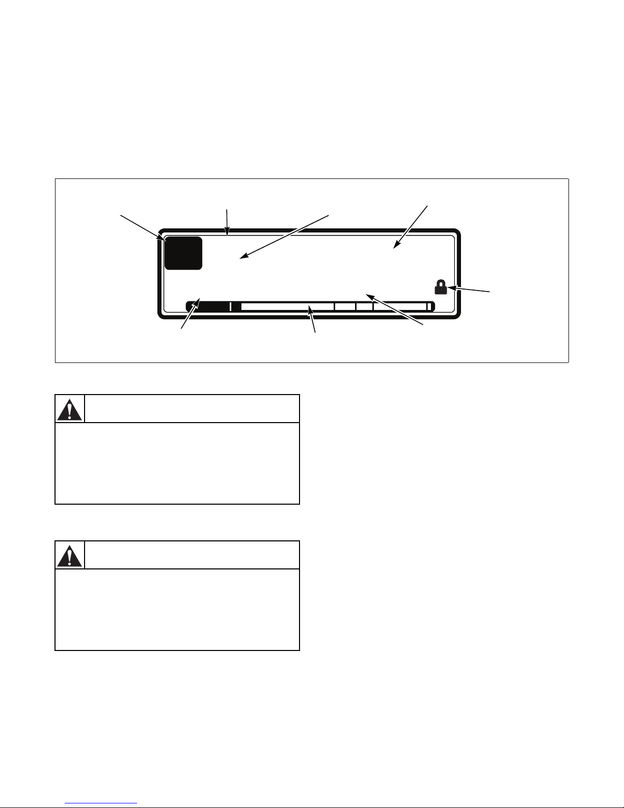
Operation
1
HOT WASH
Rinse
Step 3
Minutes
35.5
CFD837N
Wash Cycle Name
Units
Progress Bar
Wash Cycle Step
Program Number
Wash/Spin Sequence
Remaining Wash Cycle Time
Door State
If “Close Door” is displayed, it is not
possible to start the washing cycle. Check
whether:
• the machine is in the basic position
• the drum door is closed
W849
WARNING
When the power supply has been cut, the
door will be automatically blocked against
opening. After cooling down the washing
bath, the door can be opened according to
the machine maintenance instructions.
W850
WARNING
Start the Washer
Micro Microprocessor
After selecting the desired wash program number,
pressing the START button will start the wash cycle.
If there is no washing program available for the
selected program number, “INVALID” will be
displayed.
End of Wash Cycle
At the end of the wash cycle, when the remaining
program time reaches “0”, “PROGRAM END” is
displayed. When “UNLOAD” appears on the display,
open the door by the door handle and take the
garments out of the washer extractor.
Figure 30
Models with the Tilt Option - Tilting the
Machine Forward to a Position Suitable
for Unloading the Linen
For models equipped with the tilt option, open and
secure the door. Refer to Figure 6. The machine may
now be tilted forward as desired, up to the extreme
forward position. Please note that it is not required to
tilt the machine all of the way forward. To tilt the
machine forward, press and hold the hanging control's
buttons 3 and 5. Refer to Figure 26. Tilting will begin
after the buttons are held for approximately 10
seconds. When the machine has tilted forward all of
the way, the tilting will stop automatically.
NOTE: Tilting is possible only when the drum door
is open.
48
© Copyright, Alliance Laundry Systems LLC – DO NOT COPY or TRANSMIT
D1590ENR2
Page 51
Operation
During unloading while the drum is
rotating, do not stand in front of the
machine. The linen comes out of the
machine by itself. Do not pull the linen out
while the drum is rotating.
W851
WARNING
Models with the Tilt Option - Unloading
the Linen
To make unloading the linen easier, use the drum
rotation function. To make the drum rotate in the tilted
position, press and hold the button for drum rotating in
the required direction (Figure 26, pos. 1 or 2) and the
green button (6) on the controller at the same time.
This will make it easier to unload the linen.
It is possible to unload the linen in just a few steps: tilt
the machine and unload the linen using the drum
rotation function. Then, tilt the machine more and
repeat the drum rotation.
Models with the Tilt Option - Tilting the
Machine to the Basic Position
After unloading the linen, tilt the machine back to the
starting position by pressing and holding the hanging
control’s buttons 4 and 5. Refer to Figure 26. Tilting
will begin after the buttons are held for approximately
10 seconds. When the machine has returned to the
basic position, the tilting will stop automatically.
NOTE: When the power supply is interrupted
during tilting, the machine remains secured in the
current position both during and after the power
supply restart.
D1590ENR2
© Copyright, Alliance Laundry Systems LLC – DO NOT COPY or TRANSMIT
49
Page 52
Maintenance
Always follow safety instructions! Do not
bypass any safety devices or their parts.
Any interference to the machine functions
and construction are prohibited! Use the
proper chemical agents which avoid
calcium sediments on heating elements
and other machine parts. Discuss this
issue with your supplier of washing
products. The manufacturer of the
machine is not responsible for the
damage of heating elements and other
machine parts due to calcium sediments.
To avoid injuries:
• Do not operate the machine with broken/
missing parts or opened covers!
• Before maintenance work, disconnect the
machine power supply!
• When the main switch is turned off, the inlet
terminals of the machine main switch are
still under current!
W852
WARNING
5. Clean up the door gaskets to remove sediments
and dirt.
IMPORTANT: Do not use solvents or acids to clean
the rubber door gasket!
IMPORTANT: Do not use oil or grease on rubber!
After the machine has been cleaned up, leave the door
open to provide venting to the machine and to prolong
the life of the door gasket. We recommend shutting off
all main inlets of electric power and steam (the laundry
main valves and switches).
Monthly or After 200 Working Hours
1. Lubricate according to Lubrication.
2. Check for leaks on external liquid soap supply
system.
IMPORTANT: Check all hose joints, screw joints
and connections on the external liquid soap system
to make sure it is leak-proof.
When replacing any parts of the machine, replace
them with original parts obtained from your dealer or
ordered through the spare parts manual.
Introduction
Due to the quality construction and reliable parts and
materials of the machine, the preventative
maintenance has been limited to a minimum of steps.
While the machine is still under warranty, call your
dealer to perform the monthly, 3 month and 6 month
procedures listed below to avoid warranty
cancellation.
Daily
Perform daily:
1. Water and steam inlets for leakage.
2. Drain valve for leakage during washing process
3. Clean the machine cabinet to remove any traces
4. Soap hoppers must be cleaned at the end of each
50
and for proper opening (the valve is in the open
position without electric current).
of washing soaps.
working day.
© Copyright, Alliance Laundry Systems LLC – DO NOT COPY or TRANSMIT
Every 3 Months or After 500
Working Hours
1. Check the bearing house for leaks.
2. Make sure the machine is disconnected from
main power supply by the laundry switch or
circuit breaker, and that the other workers are
well informed about the machine maintenance
activity.
3. Check the tightness of the bolts.
4. Visually inspect the pipes and hose connections
inside the machine for leakage.
5. Make sure that the control components are
protected against moisture and dust during clean
up. Wipe and clean the machine inside.
6. Lubricate according to Lubrication.
7. On machines with electric heating, check the
tightness of the heating element terminal contacts
and other power terminals (main switch, fuse
disconnectors, contactor, etc.).
8. Put the covers back and switch on the power
supply by the main laundry switch or circuit
breaker.
9. If there is an earth leakage trip installed in the
inlet circuit of the laundry electric switch board,
test it according to Earth Leakage Trips.
D1590ENR2
Page 53
Maintenance
Before removing top or back panel of the
machine, switch power off and wait for at
least 10 minutes. Before starting
inspection of the frequency inverter,
check for residual voltage across main
circuit terminals + and -. This voltage
must be below 30 VDC before you can
access the inverter for inspection.
W853
WARNING
Every 6 Months or After 1000
Working Hours
1. Clean the steam inlet filters according to Steam
Filters.
2. Remove the rear machine cover and check the
condition and tightness of the V-belts (Driving
Mechanism).
3. Clean and remove dirt and dust from:
• the cooling fan of the inverter
• the motor cooling fans
• the internal ventilator of the inverter (if
present)
• the external ventilator (if present)
• the external air relieves of the machine
• check if ventilator in cooling fans of inverter
(if present) is functional
• check if external ventilator (if present) is
functional
Safety Vibration Switch
Function Description - Models 75/335,
90/400 and 125/520
The unit contains the vibration switch (Figure 32,
pews. 5) with a flexible controlling element which is
attached to a holder (7) by nuts (6) and this entire
assembly is bolted to the bottom of the switchboard
(4). The switch controlling element is inserted into the
rubber bushing (3) located into the limiter (2) which is
bolted to the drum front face (1). The switch attached
to the switchboard is a part of the machine skeleton
which is attached to the frame and the limiter with the
bushing is a part of the assembly that vibrates. The
vibration switch sensibility is given by a mutual
adjusting of these two components which controls the
unbalance level of linen in the drum.
Function Description - Models 180/800,
230/1000 and 275/1200
The vibration Switch is an important safety element
which must – if correctly adjusted – stop the machine
if excessive vibration and shaking occurs due to an
unbalance caused by improper distribution of linen in
the washing drum. Because this component is very
important, it is recommended that at the first
installation and then once in a year the vibration
switch is verified by a qualified worker.
The unit contains the vibration switch (Figure 33,
pews. 4) with a flexible controlling element, which is
attached to a holder (6) by nuts (5) and the entire
assembly is bolted to the rigid machine frame (3). The
switch controlling element is inserted into the limiters
(2) which is bolted to the front part of moving frame
(1). The limiters are a part of the assembly that
vibrates. The vibration switch sensibility is given by a
mutual adjusting of these two components which
controls the unbalance level of linen in the drum.
D1590ENR2
© Copyright, Alliance Laundry Systems LLC – DO NOT COPY or TRANSMIT
51
Page 54
Maintenance
Do this carefully to avoid injuries by
moving and non-moving parts of the
machine! After you have checked the
function, mount all panel covers back to
their original places.
W854
WARNING
Sensibility Adjustment - Models 75/335,
90/400 and 125/520
1. By moving limiter (Figure 32, pews. 2) up or
down (direction A), you will adjust the center of
rubber bushing to the control element axis of
vibration switch.
2. By moving the vibration switch on the holder (7)
to the left, you will increase the sensibility and to
the right you decrease it (direction B). To reach
the maximum permitted unbalance value it is
necessary to keep the distance of 100 mm (3.93
in.) between the limiter (2) and the vibration
switch (5) - see the side view.
Moving the holder (7) with the switch left or right
(direction C) you will center the switch control
element in the rubber bushing of the liner.
Sensibility Adjustment - Models 180/800,
230/1000 and 275/1200
1. Set a distance of 12 mm (0.47 inches) between
the limiters (2).
2. By moving the vibration switch (4) on the holder
(6) to the left, you will decrease the sensibility
and to the right you increase it (direction A). To
reach the maximum permitted unbalance value, it
is necessary to keep the distance of 60 mm
(2.36 inches) between the limiters (2) and the
vibration switch (4).
3. Moving the holder (6) with the switch left or
right (direction B) you will center the switch
control element to the distance axis between the
limiters (2).
Verifying the Function
Verify the function as follows:
1. Open the control panel cover.
2. Start extraction mode.
3. After reaching the maximum RPM, carefully
switch over the vibration switch by moving the
flexible control element manually.
52
© Copyright, Alliance Laundry Systems LLC – DO NOT COPY or TRANSMIT
D1590ENR2
Page 55
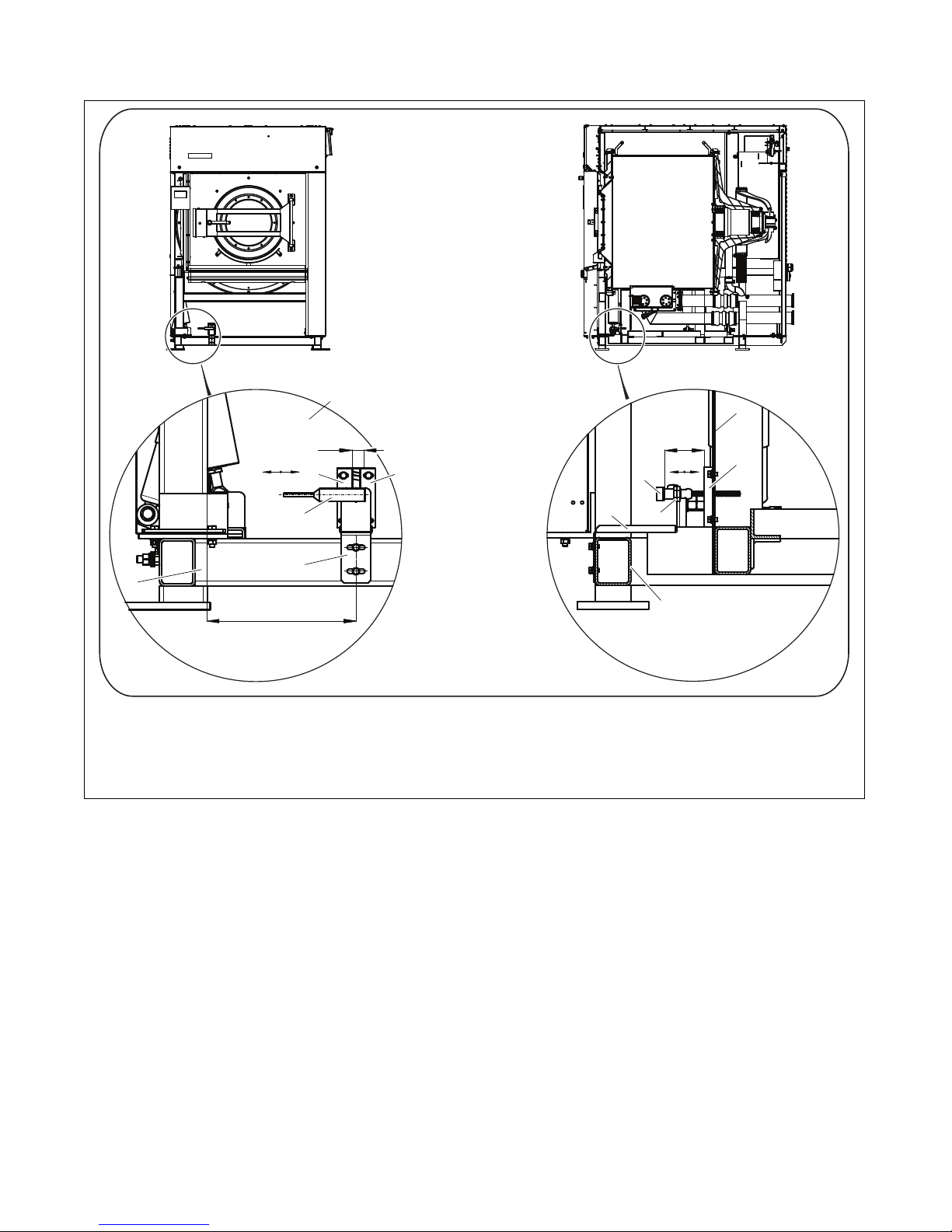
Maintenance
1
2
3
4
5
6
60 mm
A
80kg/180lb = 250 mm/9,84 in.
100kg/230lb = 497 mm/19,57 in.
120kg/275lb = 353 mm /13,90 in.
1
12 mm
2
B
2
3
4
6
CFD954N
1 Front part of moving frame 4 Vibration switch
2 Limiters 5 Adjusting nut
3 Machine frame 6 Vibration switch holder
Figure 31
D1590ENR2
© Copyright, Alliance Laundry Systems LLC – DO NOT COPY or TRANSMIT
53
Page 56
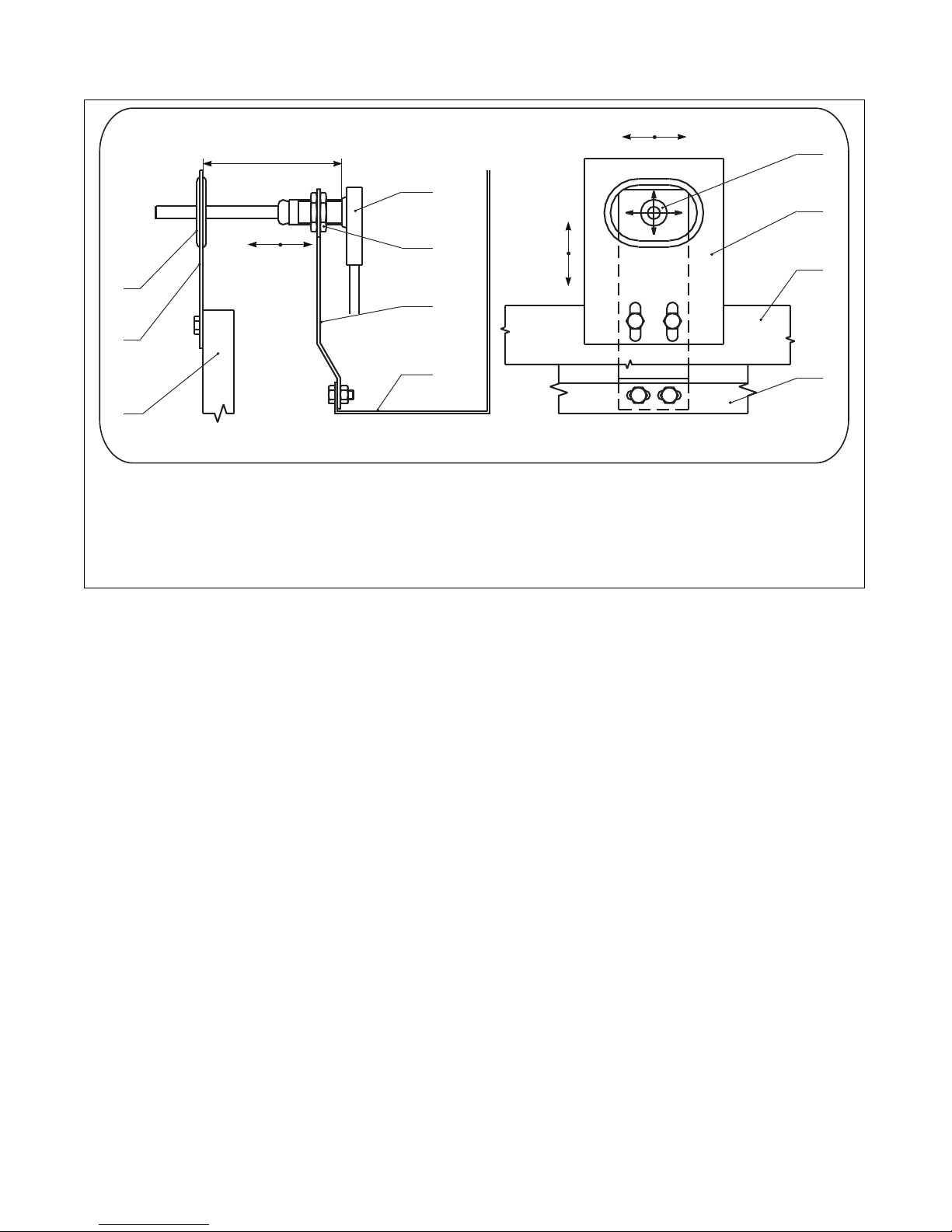
Maintenance
100 mm/3,94"
SIDE VIEW FRONT VIEW
3
2
1
5
6
7
4
B
C
A
5
2
1
4
1 Front face of the drum 5 Vibration switch
2 Limiters 6 Adjusting nut
3 Bushing 7 Vibration switch holder
4 Switchboard bottom
CFD969N
Figure 32
54
© Copyright, Alliance Laundry Systems LLC – DO NOT COPY or TRANSMIT
D1590ENR2
Page 57
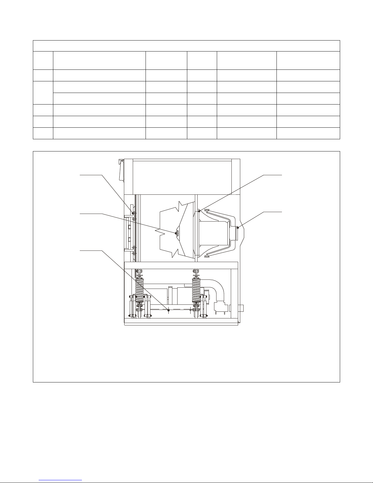
Torque Specifications - 75/335, 90/400 and 125/520 Models
A
B
C
D
E
Maintenance
Bolt
(Nut)
Models Dimension Amount
Tightening Moment
(Nm)
Tightening Moment
A 75 / 335, 90 / 400 and 125 / 520 M20x65 24 600 443
B
75 / 335, 90 / 400 and 125 / 520 M12x30 8 70 52
75 / 335 KM13 1 450 332
C 75 / 335, 90 / 400 and 125 / 520 M12x35 6 70 52
D 75 / 335, 90 / 400 and 125 / 520 M30x80 1 800 590
E 75 / 335, 90 / 400 and 125 / 520 M12x38 4 25 18.5
Table 17
(lb. ft.)
A Bolts of Hub flange D Bolts fixing the inner drum to the shaft
B Bolts fixing the pulley to the nut of clamping sleeve E Bolts fixing the door brackets
C Bolts fixing the motor plate to the external drum
A spanner for the jam nut KM 13 is not a part of the delivery or accessories.
D1590ENR2
© Copyright, Alliance Laundry Systems LLC – DO NOT COPY or TRANSMIT
CFD970N
Figure 33
55
Page 58
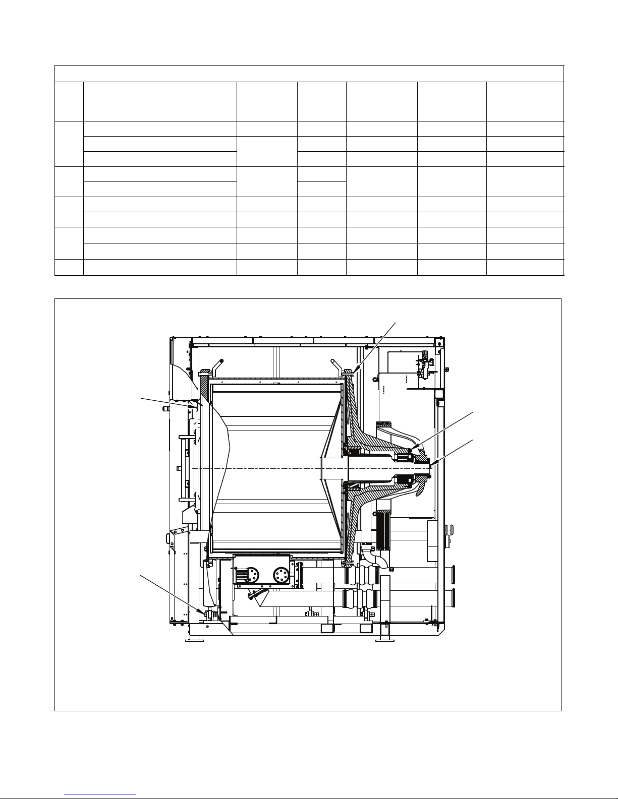
Maintenance
A
B
C
D
E
Torque Specifications - 180/800, 230/1000 and 275/1200 Models
Bolt
(Nut)
Models Dimension Amount
Tightening
Moment
(Nm)
Tightening
Moment
(lb. ft.)
180 / 800 M16x70 24 200 148 8.8
A
B
230 / 1000 and 275 / 1200 7
C
D
230 / 1000
275 / 1200 32 350 258 8.8
180 / 800
M20x70
M10x60
24 350 258 8.8
7
20 15 A2
180 / 800 and 230 / 1000 M10x30 8 20 15 4.8
275 / 1200 M12x30 8 36 27 4.8
180 / 800 M10x60
444 32 8.8
230 / 1000 and 275 / 1200 M10x60 6 44 32 8.8
E 180 / 800, 230 / 1000 and 275 / 1200 M16x75 12 88 65 4.8
Table 18
Bolt
Type
CFD955N
A Hub flange bolts D Bolts fixing the pulley to the nut of
B Bolts fixing the door hinges clamping sleeve
C Bolts fixing the bearing house cover E Bolts fixing the spring nut
Figure 34
56
© Copyright, Alliance Laundry Systems LLC – DO NOT COPY or TRANSMIT
D1590ENR2
Page 59
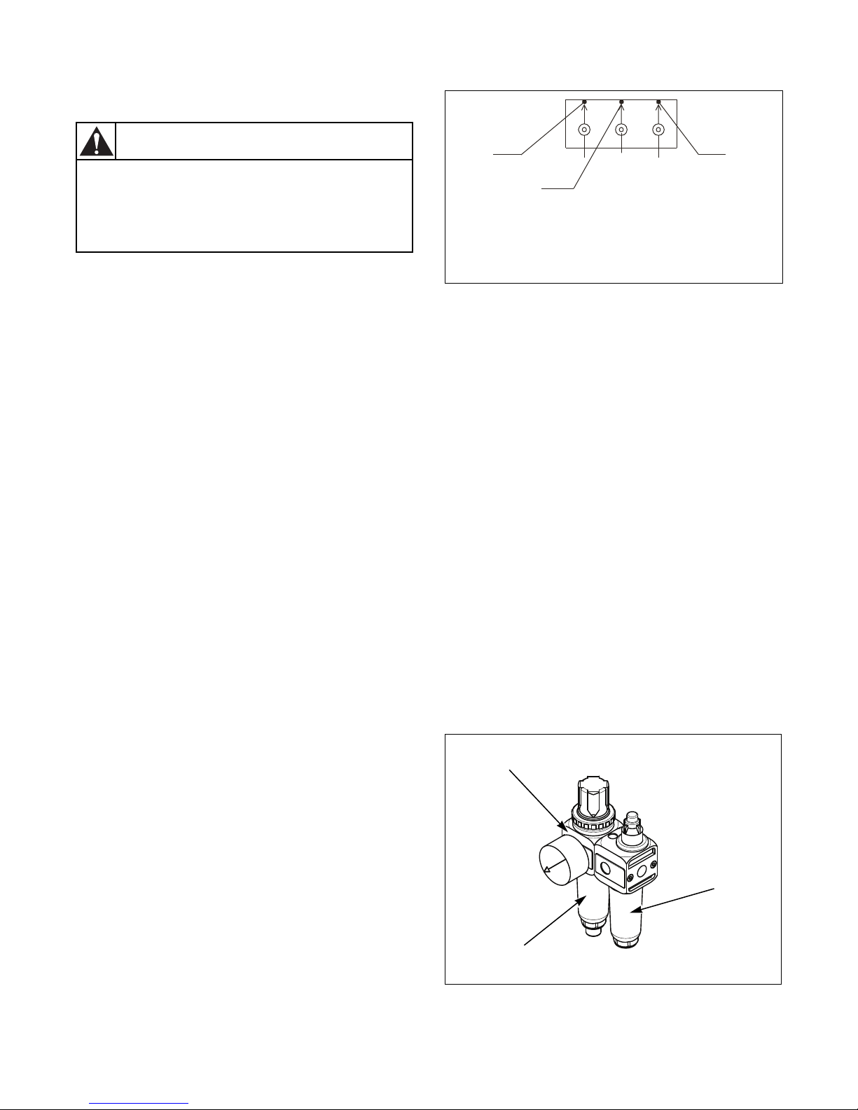
Lubrication
Do the lubrication work only when the
main switch is off and all components
have been stopped (if not stated
otherwise in following instruction)!
W855
WARNING
1
2
3
Lubricator pot
Condensation trap
Pressure regulator
Every time you use a grease gun, especially for
greasing bearings and seals, do it slowly - not faster
than 5 strokes in 1 minute. The grease gun can create a
high pressure which can cause seal deformation and
consequent leakage. Never operate the grease gun
faster even if the grease contains air gaps.
Over-lubrication can cause the same damage as
insufficient lubrication.
Always make sure that your grease gun is in perfect
condition.
If you substitute the lubricant by another type make
sure that these two kinds are compatible, otherwise
there is a risk of bearing failure. For example, lithium
lubricants are compatible with calcareous lubricants
but not with sodium ones.
IMPORTANT: Never mix petroleum lubricants
with silicone lubricants!
Lubrication Points, Quantity and
Lubrication Periods - Models 75/335,
90/400 and 125/520
Lubricant
Use a multipurpose lithium lubricant containing highpressure additives of consistency NLGI 2.
SKF - LGEP 2
ESSO - BEACON EP 2
Maintenance
CFD971N
1 Rubber seal lubricator
2 Front bearing lubricator
3 Rear bearing lubricator
Figure 35
Quantity of Lubricant
2 cm³ (2 strokes) - once in a month or every 200
working hours, which ever comes first.
Lubrication Points, Quantity and
Lubrication Periods - Models 180/800,
230/1000 and 275/1200
Once in 6 months or when needed, grease spring
suspension eyes (Figure 42, pos. 4), guiding rods
(pos. 5), the door handle casing (Figure 39, pos. 2) and
the casings in the door hinge (Figure 39, pos. 7). The
motor bearings are maintenance-free (do not
lubricate).
The hubs of machines are maintenance-free.
Pneumatic Lubricator
Fill the lubricator pot with approximately 23 cm³ of
oil. Refer to Figure 36.
Recommended types of oil: non-detergent and without
aggressive additives, viscosity VG32 (ISO 3448). E.g.,
oil for pneumatic devices or hydraulic oil.
Lubricators
For main bearings and seals, lubricators are located on
the rear machine cabinet and marked by the symbol
“Lubrication point”. Refer to Figure 35. Lubricators
can also be marked by text “Lubrication”. Press the
lubricant in slowly and let the drum rotate with the
same speed as during washing.
D1590ENR2
© Copyright, Alliance Laundry Systems LLC – DO NOT COPY or TRANSMIT
CFD839N
Figure 36
57
Page 60
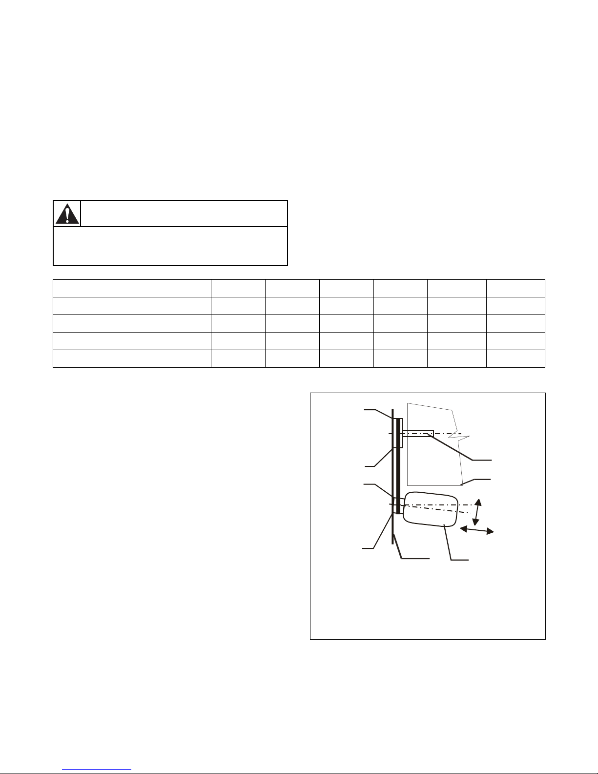
Maintenance
Before you start, turn off the main switch
to avoid possible injuries!
W856
WARNING
1
4
A
B
C
D
3
2
Driving Mechanism
The belts are accessible after the rear or side cover has
been dismantled. if the belts are too tight, the bearing
On new machines and after a belt replacement, make
an inspection of the belt tightness:
1. After first 24 hours of operation
2. After first 80 hours of operation
3. Every 6 months or every 1000 operation hours whichever comes first.
Inspection of Belt Tightness
seatings are under stress and their life service has been
shortened.
If the belts are too loose, they can slip on the pulley
and cause noisy operation.
In the case of need, tighten the belts. Change the belts
if worn out or damaged.
Testing force of belt tensioning which can be
measured by tension meter is indicated in Tabl e 1 9 .
The procedure for approximate belt tensioning
according to the force measured by the tension meter:
Apply a load at the middle of the belt. The data is valid
only for belts from the manufacturer.
Model 75/335 90/400 125/520 180/800 230/1000 275/1200
Belt Deflection, mm (in.) 20 (.78) 20 (.78) 20 (.78) 12.3 (.48) 9 (.35) 9 (.35)
Force in Belt Deflection, N 53 - 54 68 - 69 68 - 69 11 - 12 20 - 22 20 - 22
Force Measured by Device, N 200 300 300 - - -
Frequency Measured by Device, Hz - - - 36 - 37 35 - 37 35 - 37
Table 19
Belt Replacement
IMPORTANT: Never use a crowbar to take off the
belts over the pulley grooves.
Loosen the bolts of the tightening pulley on the drum
rear wall and the adjusting screw for taking the belts
off. Always change a complete set of the belts. Always
use the same type of belts in the same set. If the
pulleys are damaged, replace them.
After the belt replacement, check the pulley alignment,
the tightness of belts, bolts and nuts. Keep the belts
and pulleys clean and free of oil, lubricants, water, etc.
Pulley Alignment
A precondition for the reliable operation and long
service life of the belts is a proper pulley alignment.
Do the inspection of the alignment by means of a ruler
(Figure 37), placing it on the pulley faces. If all points
(A, B, C, D) are touching the ruler, the pulleys are
1 Main housing with the pulley
2 Drum
3 Drive motor
4 Ruler
aligned.
Figure 37
CFD844N
58
© Copyright, Alliance Laundry Systems LLC – DO NOT COPY or TRANSMIT
D1590ENR2
Page 61
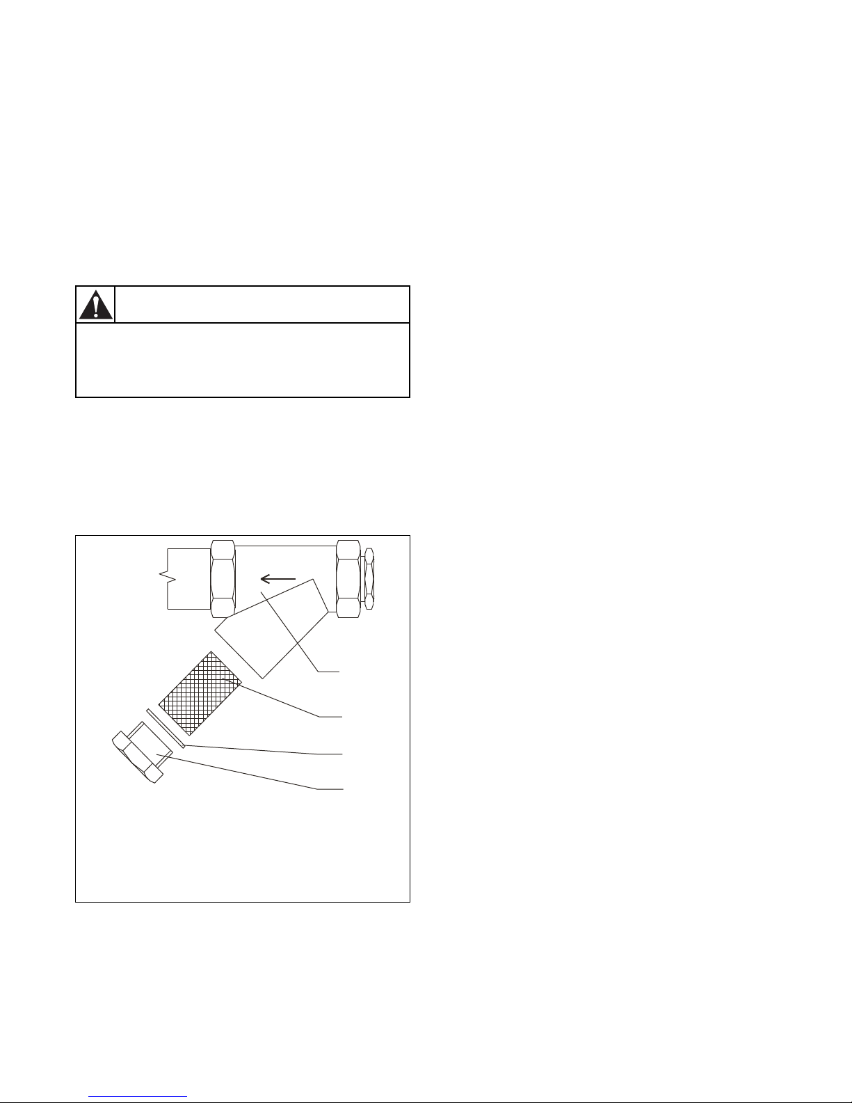
Maintenance
Before you start cleaning the filter, check
to see if the steam inlet to machine is
closed and cold!
W857
WARNING
1
2
3
4
Steam Filters
Machines are equipped with filters on steam inlets
(if the machine has steam heating). It is necessary to
clean up the filters occasionally to avoid a
prolongation of filling the machine with water.
Intervals between cleaning depend on the quantity of
foreign particles in the water line.
Cleaning the Filter
1. Stop the steam inlet to the machine.
2. Unscrew the filter plug (Figure 38, pos. 4) and
remove the filter sieve (2).
3. Clean the sieve with running water or
compressed air.
4. Put the sieve (2) and gasket (3) back on the filter
body (1) and tighten the plug (4).
Thrust of Door Seal
If there is water leakage around the door, check to see
if it has been caused by the door shifting out of its
position or if the door seal thrust should be adjusted. In
some cases the door seal has to replaced.
Adjusting on the Side of the Door Handle
1. Unscrew the bolt (Refer to Figure 39 for 75/335,
90/400 and 125/520 models and to Figure 40 for
180/800, 230/1000 and 275/1200 models, detail
“B”, pos. 1), securing the casing of the door
handle (2).
2. Unscrew the casing (2) from the door bearer (3)
always by a whole turn so that the groove in the
casing thread (2) appears below the securing bolt
(1).
3. To make the casing turning (2) easier, use the
semicircle notches (4) between the casing (2) and
the handle pin (5), in which you insert a
cylindrical object (a bolt, etc.). By turning the
handle, the casing (2) will also move.
4. After the door thrust has been adjusted, tighten
up the securing bolt (1) to the groove in the
casing (2) thread.
1 Filter body
2 Filter sieve
3 Gasket
4 Plug
Figure 38
D1590ENR2
© Copyright, Alliance Laundry Systems LLC – DO NOT COPY or TRANSMIT
CFD845N
59
Page 62
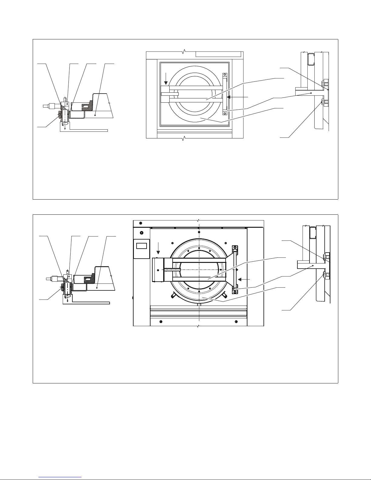
Maintenance
“B”
4
1
532
“B”
“C”
“C”
8
3
7
9
6
“B”
“B”
“C”
“C”
4
1
53
8
3
7
9
6
2
1 Handle bolt 6 Hinge bolt
2 Handle sleeve 7 Hinge
3 Door carrier beam 8 Elimination washer
4 Semicircle cuts 9 Door
5 Handle pin
CFD972N
Figure 39
CFD956N
1 Handle bolt 6 Hinge bolt
2 Handle sleeve 7 Hinge
3 Door carrier beam 8 Elimination washer
4 Semicircle cuts 9 Door
5 Handle pin
Figure 40
60
© Copyright, Alliance Laundry Systems LLC – DO NOT COPY or TRANSMIT
D1590ENR2
Page 63
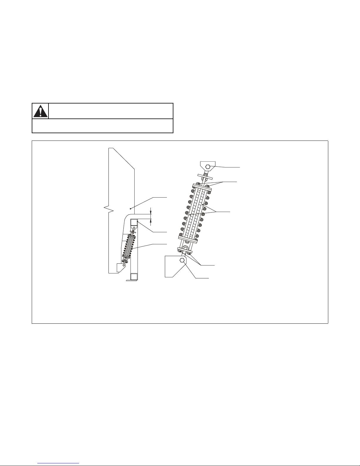
Maintenance
MAIN SWITCH MUST BE OFF!
WARNING!
X
4
5
1
6
2
6
2
3
Spring Unit - Models 75/335, 90/400
and 125/520
Adjusted by manufacturer.
Spring units are to be adjusted in the case that you
found out the suspended machine part is not in a
horizontal position (without linen and water) or after
the spring unit has been replaced. Refer to Figure 41.
The spring unit adjusting is achieved by turning the
nuts (2) with the same number always simultaneously
on the opposite guiding rod (3) of spring unit.
The adjustment is correct when a same gap in all four
corners of the suspended machine part has been
achieved. (X = 55 mm/ 2.16 inches) between the plate
edge (4) of the vibrating part and the frame top surface
(5).
1 Spring unit 4 Suspended part
2 Adjusting nuts 5 Machine frame
3 Guiding rods 6 Spring suspension eyes
D1590ENR2
© Copyright, Alliance Laundry Systems LLC – DO NOT COPY or TRANSMIT
CFD975N
Figure 41
61
Page 64
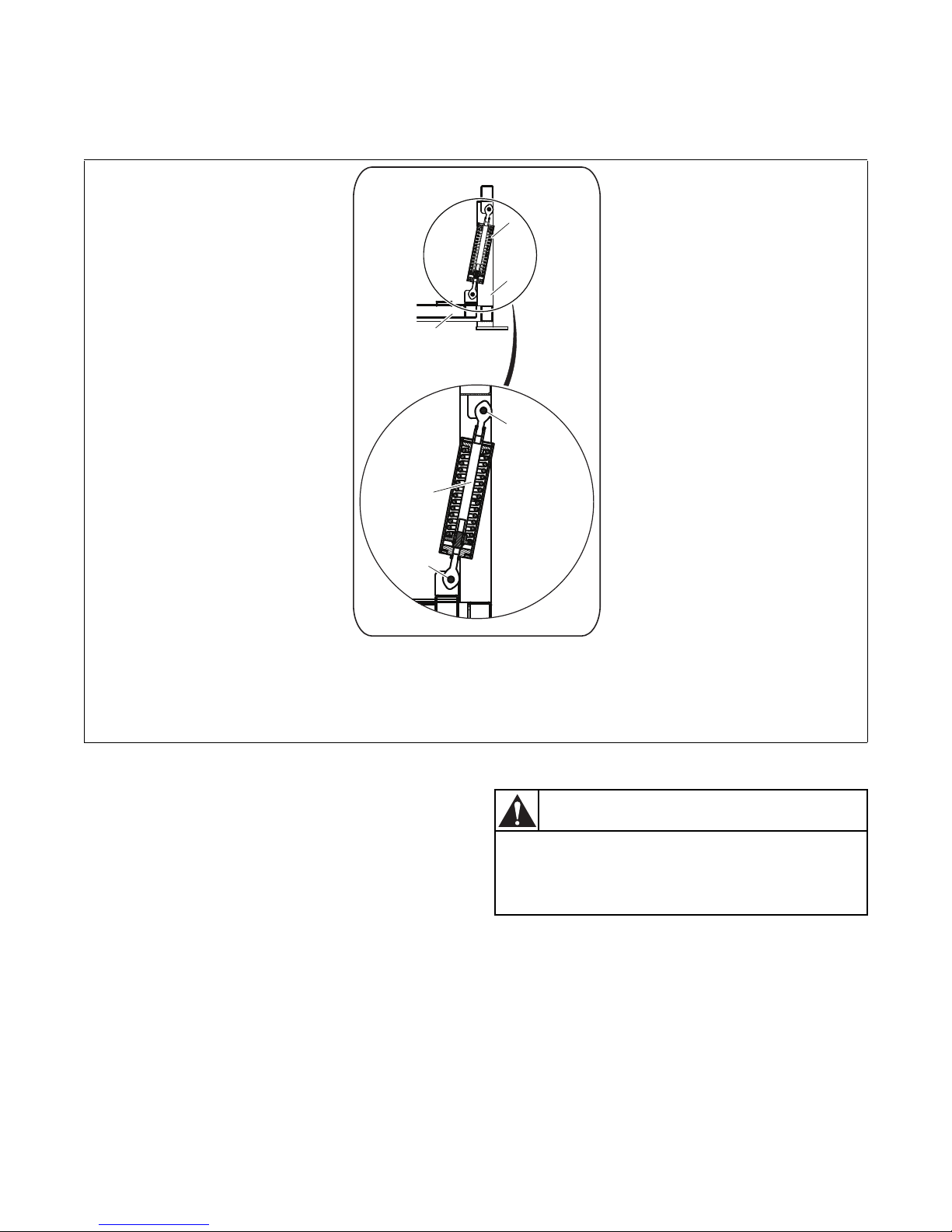
Maintenance
1
3
2
5
4
4
A qualified worker must perform a test of
the earth leakage trip function at least
once every 3 months.
W858
WARNING
Spring Unit - Models 180/800, 230/1000 and 275/1200
Adjusted by manufacturer.
1 Spring unit 4 Suspension spring eyes
2 Machine frame 5 Guiding rods
3 Suspended part
Replacement Washer Fuses
Fuse Values
The correct values of fuses can be found in the vicinity
of the fuse holders, on the electrical scheme and
delivered with the machine. When a fuse is blown, you
can replace it with the same value but NOT with a
higher value. If the fuse blows again, do not change it,
but find the cause of the failure. Contact your
distributor for help if necessary.
Earth Leakage Trips
If the laundry is equipped with the earth leakage trip in
the inlet circuit of the electric switchboard, it is
necessary to test it regularly. The earth leakage trip is a
very sensitive device which provides a safety for
operators avoiding the risk of electric shock while the
machine is in operation.
62
© Copyright, Alliance Laundry Systems LLC – DO NOT COPY or TRANSMIT
CFD957N
Figure 42
The Test Procedure
Press the test push button of the earth leakage trip
while it is under tension. The earth leakage trip must
go off!
D1590ENR2
Page 65
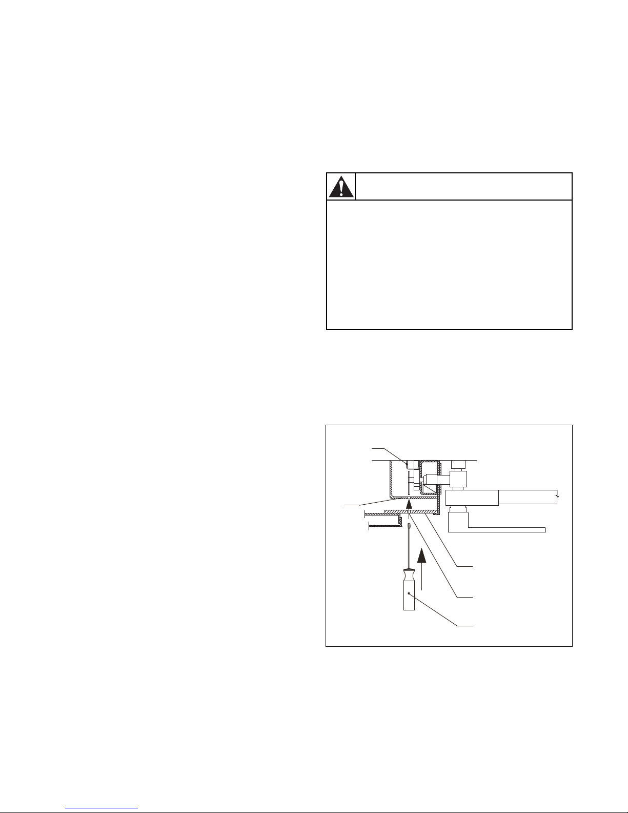
Troubleshooting Aids
Before the emergency door opening, turn
off the machine main switch! Never open
the door while drum is still running! Never
open the door if “Too Hot” is indicated!
Risk of burn or scald injuries! Never open
the door if the machine parts feel too
warm! Do not open the door until there is
no water in the drum or the water will flow
out after opening the door!
W859
WARNING
1
4
5
2
3
Door Blocking
Description of Door Lock Function
The door lock has been designed as a compact unit. Its
function is to secure the door against the opening
during the washing cycle. When the cycle is finished,
the unlocking is done automatically by a programmer.
The lock is also blocked during failure situations, e.g.,
electric network black out, before and after the
machine installation, etc. You can unlock it in case of
an emergency according to the procedure hereafter
described.
Lock without Tensions before the
Program Start
It is possible to open and shut the washing machine
door any time. The lock will not be blocked; coils with
the latch are not active.
Main Switch and Emergency Stop Button
are Switched On
Door Shutting
The lock is secured by a blocking latch after the door
is shut and the program has been started. In this
moment, it is not possible to open the door.
Unblocking the Door Lock in Case of
Emergency
If the power blackout takes too long, you can make an
emergency unblocking of the door lock. The
emergency door opening procedure is as follows:
1. Verify if all conditions are present to safely open
the door.
2. For 75/335, 90/400 and 125/520 models, insert a
tool with a maximum diameter of 5.5 mm
(.21 in.) into the finger protection hole in the door
lock cover and push softly. Refer to Figure 44.
Door Opening
The door can be opened after the lock is unblocked
and when the blocking latch moves to the non-active
position. This situation occurs at the end of a program
or when pressing the Stop button.
Current Failure During Operation
When the power supply has been interrupted during a
wash cycle, the door lock stays in a blocked position,
and the door cannot be opened.
D1590ENR2
© Copyright, Alliance Laundry Systems LLC – DO NOT COPY or TRANSMIT
CFD973N
Figure 43
63
Page 66
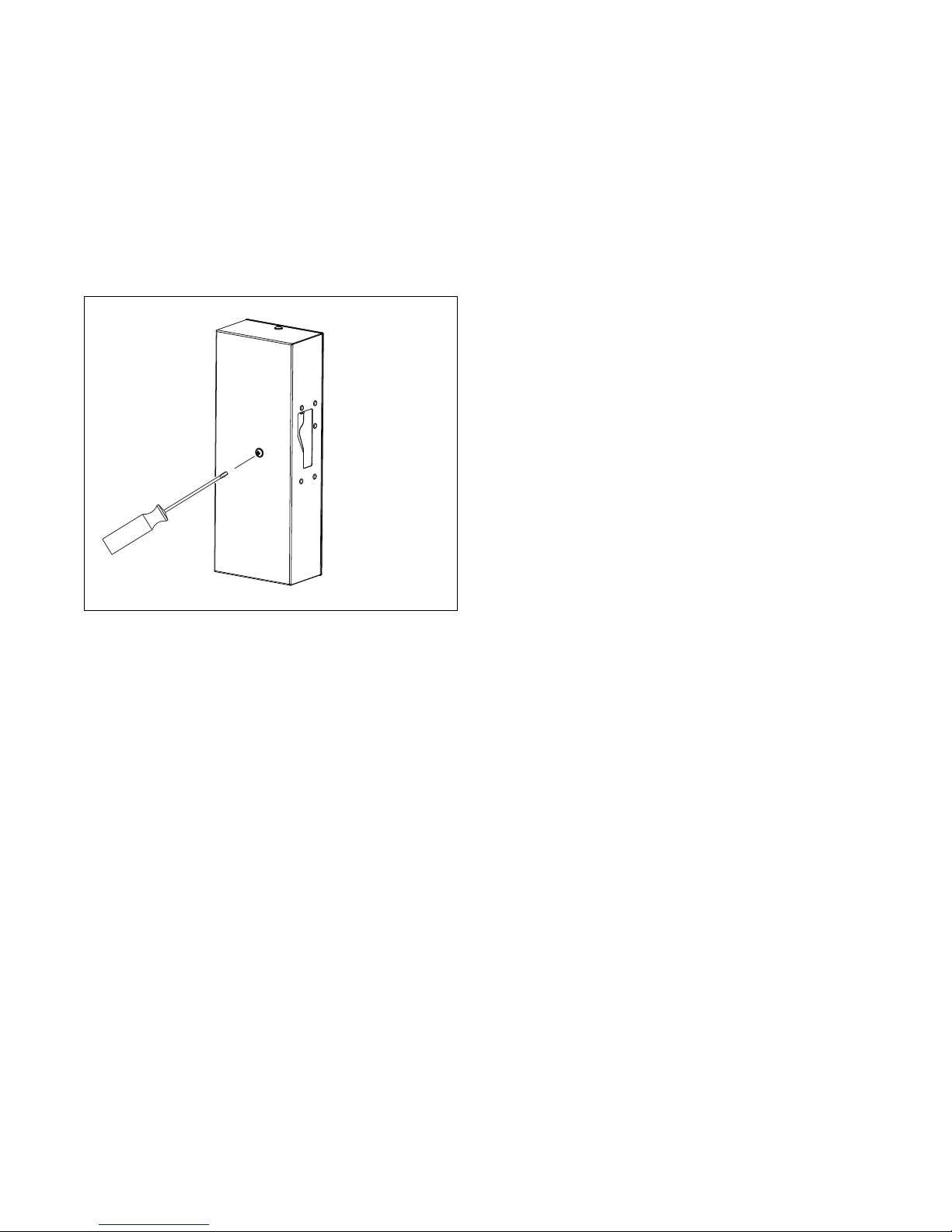
Troubleshooting Aids
3. For 180/800 and 275/1200 models unscrew the
bolt in the lock cover, Refer to Figure 44. Insert a
screwdriver into the hole in the lock cover and
push softly.
4. By this, the latch mechanism is lifted up and the
lock is unblocked. The lock stays unblocked even
after the tool removal.
5. Open the door if all safety conditions are
fulfilled.
CFD848N
Figure 44
Error Indication Shown on Display
See Programming Manual.
64
© Copyright, Alliance Laundry Systems LLC – DO NOT COPY or TRANSMIT
D1590ENR2
Page 67

Putting the Machine out of Service
If the machine is out of service, follow these
instructions.
Disconnecting the Machine
1. Switch off the external electric power inlet to the
machine.
2. Turn off the main switch on the machine rear.
3. Shut the external steam inlet to the machine.
4. Make sure that the external electric power steam
inlets are shut off. Disconnect all electric, water
or steam inlets.
5. Insulate the external electric power inlet
conductors.
6. Equip the machine with an “Out of service” sign.
7. Unscrew nuts (bolts) fixing the machine to the
floor.
8. During transportation, follow the instructions
Important Information Before Installation and
Handling, Transportation and Storage.
If the machine will never be used again, secure it so
that injury of persons, damage to health, property and
nature is avoided. Make sure persons or animals can
not be enclosed inside the machine and injury of
persons by moving or sharp parts of the machine can
not occur (e.g., remove the door, secure the drum
against turning, etc.).
IMPORTANT: Be careful: falling door and glass
can cause injuries!
D1590ENR2
© Copyright, Alliance Laundry Systems LLC – DO NOT COPY or TRANSMIT
65
Page 68
Putting the Machine out of Service
Take all necessary action and precautions
when disassembling the washer to avoid
injuries by glass or sharp metal edges.
W860
WARNING
Machine Disposal
Possibility of the Machine Disposal by a
Specialized Company
Information concerning the WEEE-directive (Waste
Electrical and Electronic Equipment, for European
Union member states only):
• For the production of the machine that you have
purchased, natural resources are being reclaimed
and used. The machine can contain substances
which are dangerous for health and environment.
• When you dispose of your machine, to avoid
spreading of these substances in our environment
and to reduce the pressure on our natural
resources, we encourage you to use the
collection, reuse and recycle system in your
region or country. These systems reuse or recycle
most of the components.
• The symbol “crossed out bin on wheels”
(Figure 45), invites you to make use of these
systems.
• If you wish more information concerning the
systems for collection, reuse or recycling of
disposed machines, you can contact the
appropriate administration in your region or
country for waste management.
• You can also contact the manufacturer for more
information concerning the environmental
performances of our products.
MIX1N
Figure 45
Possibility of the Machine Liquidation by
Own Potential
It is necessary to sort out the parts for metal, nonmetal, glass, plastics, etc., and bring them to recycling
places. The sorted out materials have to be classified
into waste groups. Offer the sorted waste to an
appropriate company for further treatment.
• Please, consider that the WEEE directive is
generally only available for household machines.
In some countries professional machines are
added, in others not. Therefore, the symbol
(Figure 45) may not be present.
• Info for dealers: Due to the diversity of the
national legislations, the manufacturer can not
take all the measures to be in accordance with all
national legislation of each member state. We
expect that each dealer who imports our
appliances into a member state (and puts it on the
market) takes the necessary steps to be in
compliance with the national legislation (as the
directive requires).
66
© Copyright, Alliance Laundry Systems LLC – DO NOT COPY or TRANSMIT
D1590ENR2
 Loading...