

Alliance Laundry Systems SGHP190F, IGHP190E, UGHP190E, IQHP190E, SQHP190E Programming Manual
...Page 1

Tumble-Dryers
Flex Control
Refer to Page 7 for Model Identification
Programming
Original Instructions
Keep These Instructions for Future Reference.
CAUTION: Read the instructions before using the machine.
(If this machine changes ownership, this manual must accompany machine.)
www.alliancelaundry.com
Part No. D1621ENR3
October 2017
Page 2

Page 3

Table of Contents
Machine Type Selection:......................................................................... 6
Model Identification .............................................................................. 7
Warnings and Symbols........................................................................... 8
Warnings........................................................................................................8
Symbols Used ............................................................................................... 9
Programming and Emergency Stop Switch.................................................. 10
Main Menu...................................................................................................11
Basic Description of Controls................................................................12
General ....................................................................................................... 12
Specific Information .....................................................................................12
20 Dryer Programs - 5 Steps.......................................................................... 13
The Creation of a Dryer Program ...................................................................13
Programming the Functions .......................................................................... 14
Initializing the Machine........................................................................ 15
Initializing Steps...........................................................................................15
Initialization Menu .......................................................................................15
Configuration Menu......................................................................................17
How to Create and Adjust a Dryer Program.....................................................22
Programming........................................................................................23
General ....................................................................................................... 23
Step 1: Program Menu ..................................................................................23
Step 2: Program Functions.............................................................................23
Step 3: Program Step Functions .....................................................................24
Step 4: Programming the Drying Part .............................................................25
Operation menu....................................................................................28
Start Up ...................................................................................................... 28
Switch On the Power.....................................................................................28
Load the Dryer............................................................................................. 28
Start a Dryer Program....................................................................................28
The Active Program ..................................................................................... 28
Advancing a Dryer Program...........................................................................28
Drying Time.................................................................................................28
Program End................................................................................................ 28
©
Copyright 2017, Alliance Laundry Systems LLC
All rights reserved. No part of the contents of this book may be reproduced or transmitted in any form or by any means without the expressed
written consent of the publisher.
©
Copyright, Alliance Laundry Systems LLC -
DO NOT COPY or TRANSMIT
3 Part No. D1621ENR3
Page 4

Cool-Down Function ....................................................................................29
Stop ............................................................................................................29
Wait State.....................................................................................................29
How to Handle Failure Messages................................................................... 29
How to Handle Power Interruptions................................................................29
Service-State Button .....................................................................................29
Humidity Control..........................................................................................30
Pre-programmed programs...................................................................32
General ....................................................................................................... 32
Drying Programs ..........................................................................................32
Troubleshooting.................................................................................... 36
Display Messages ........................................................................................ 36
Fault Messages ............................................................................................ 36
How to Handle Fault Messages ..................................................................... 36
Clean Filter ................................................................................................. 37
Overview..................................................................................................... 37
Service Menu .............................................................................................. 39
Diagnostic Program ......................................................................................41
Problem Check List.......................................................................................42
Explanation of Error Messages.......................................................................43
Failure 1: Heating Safety 1.........................................................................43
Failure 2: Heating Safety 2.........................................................................43
Failure 3: Pressure Sensor Low ..................................................................43
Failure 4: Pressure Sensor High ................................................................. 44
Failure 5: Motor Thermic........................................................................... 44
Failure 6: Fan Motor Thermic.....................................................................44
Failure 7: Drum Motor Thermic..................................................................45
Failure 8: Airflow Switch Open at Start-up.................................................. 45
Failure 9: Airflow Switch Open After Start-up............................................. 45
Failure 10: Airflow Switch Closed.............................................................. 46
Failure 11: Fault Cool down....................................................................... 46
Failure 12: No Reheating........................................................................... 46
Failure 13: No Heating...............................................................................47
Failure 14: Heat time ................................................................................ 47
Failure 15: Too Hot................................................................................... 47
Failure 18: Too Hot Safety......................................................................... 48
Failure 19: Defective Temperature Sensor 1................................................. 48
Failure 20: Defective Temperature Sensor 2................................................. 48
Failure 25: No Humidity Sensor (HUMIDITY CONTROL ONLY)................49
Failure 26: No Humidity Sensor Cap (HUMIDITY CONTROL ONLY)......... 49
Failure 27: No Humidity Reduction.............................................................49
Failure 28: Lint Filter.................................................................................50
Failure 29: Timeout Cooldown .................................................................. 50
Failure 35: Wrong Software Version............................................................50
Failure 37: Too Hot Safety......................................................................... 50
Failure 39: Error Fan .................................................................................51
Failure 40: Phase Error ..............................................................................51
Failure 41: Service Due .............................................................................52
©
Copyright, Alliance Laundry Systems LLC -
DO NOT COPY or TRANSMIT
4 Part No. D1621ENR3
Page 5

Failure 95: Watch Dog............................................................................... 52
Failure 150-165: Memory Errors.................................................................52
Failure 170-199: Sofware Errors................................................................. 52
Humidity Control - Troubleshooting............................................................... 52
Service information...............................................................................54
General........................................................................................................ 54
Maintenance ................................................................................................54
Information for Service .................................................................................54
Programmer Circuit Board ............................................................................ 54
Instructions for Replacing the Electronic Board and Keypad ............................ 54
Instructions for Installing New Software ........................................................ 55
Specification of Your Machine...............................................................56
©
Copyright, Alliance Laundry Systems LLC -
DO NOT COPY or TRANSMIT
5 Part No. D1621ENR3
Page 6

Machine Type Selection:
Machine Type Selection:
Dry load capacity
Tumble Dryer 190 Liters
(9Kg)
250 Liters
(11Kg)
285 Liters
(13Kg)
345 Liters
(16Kg)
“Machine
type” selection
» T9
» T11
» T13
» T16
©
Copyright, Alliance Laundry Systems LLC -
DO NOT COPY or TRANSMIT
6 Part No. D1621ENR3
Page 7

Model Identification
Information in this manual is applicable to these models:
190 Liters (9 Kg) IGHP190E SGHP190E UGHP190E
IGHP190F SGHP190F UGHP190F
IQHP190E SQHP190E UQHP190E
IQHP190F SQHP190F UQHP190F
IUHP190E SUHP190E UUHP190E
IUHP190F SUHP190F UUHP190F
IWHP190E SWHP190E UWHP190E
IWHP190F SWHP190F UWHP190F
250 Liters (11 Kg) IGHP250E SGHP250E UGHP250E
IGHP250F SGHP250F UGHP250F
IQHP250E SQHP250E UQHP250E
IQHP250F SQHP250F UQHP250F
Model Identification
IUHP250E SUHP250E UUHP250E
IUHP250F SUHP250F UUHP250F
IWHP250E SWHP250E UWHP250E
IWHP250F SWHP250F UWHP250F
285 Liters (13 Kg) IGHP285E SGHP285E UGHP285E
IGHP285F SGHP285F UGHP285F
IQHP285E SQHP285E UQHP285E
IQHP285F SQHP285F UQHP285F
IUHP285E SUHP285E UUHP285E
IUHP285F SUHP285F UUHP285F
IWHP285E SWHP285E UWHP285E
IWHP285F SWHP285F UWHP285F
345 Liters (16 Kg) IGHP345E SGHP345E UGHP345E
IGHP345F SGHP345F UGHP345F
IQHP345E SQHP345E UQHP345E
IQHP345F SQHP345F UQHP345F
IUHP345E SUHP345E UUHP345E
IUHP345F SUHP345F UUHP345F
IWHP345E SWHP345E UWHP345E
IWHP345F SWHP345F UWHP345F
©
Copyright, Alliance Laundry Systems LLC -
DO NOT COPY or TRANSMIT
7 Part No. D1621ENR3
Page 8

Warnings and Symbols
Warnings and Symbols
Warnings
WARNING
Before operating a machine controlled by an electronic programmer, read this manual. Incorrect use
can result in serious injuries or damage to the machine controls. Ignoring instructions can cause an
incorrect machine function, which may result in injuries or machine and/or linen damages.
• This English version is the original version of this manual.
Without this version, the instructions are incomplete. Before
installation, operating and maintenance of the machine, read
complete instructions thoroughly. Refer to the Installation/
Operation/Maintenance manual for further important instructions, as well. Follow these and keep the manuals accessible
for later use.
• A machine must be installed by following the Installation/
Operation/Maintenance manual. Before the first machine
start, it must be initialized and tested by a qualified technician.
• The electric service line must not be affected by other electrical loading. A nominal voltage, if loaded or not must work in
the range ±10% with a maximum permanent frequency deviation of 1% or a short-time one at 2% of a given frequency.
NOTE: Connecting or starting the machine at an incorrect voltage can damage the programmer.
• The machine must not be exposed to high humidity or extreme high and low temperatures.
• Do not tamper with the controls.
C001
or inquiries addressed to the distributor or manufacturer.
NOTE:
The FLEX CONTROL computer uses "machine type"
codes to select the different programmable machine
versions.
The model number on the machine doesn’t indicate the
"machine type" but must be linked with the description
of the "machine type" letters.
• Tx : Single Dryer
• Tx, x : Double Dryer
INSTRUCTIONS IN THIS MANUAL DO NOT COVER
ALL DANGEROUS SITUATIONS. IT IS UP TO THE USER
TO HANDLE THE MACHINE CAREFULLY.
• The manufacturer has the right to change specifications in this
manual without prior notice. All the stated information is only
for informative purpose and must be considered as general. It
is not possible to present all the specific data of the device.
NOTE:
Every circuit board has a serial number and the code of
the board (Refer to Figure 1).
On the EPROM memory chip on the circuit board is a
label specifying the software number and version
and/or the date of the software. (Refer to Figure 1).
These data, as well as the model and serial number of
the machine, must be mentioned in all correspondence
©
Copyright, Alliance Laundry Systems LLC -
DO NOT COPY or TRANSMIT
8 Part No. D1621ENR3
Page 9

Symbols Used
CFD1307R_SVG
BUTTONS
BUTTONS
Warnings and Symbols
Figure 1 U models
START
- Starting up a program
- Continue an interrupted program
- Advancing the program step by step
STOP
- Interrupting a program
- Finishing a program
CONFIRM THE SELECTION
Figure 2 I models, S models
REVERSE
- Switch On/Off Reverse function
SERVICE
- shows the states and the total number of cycles of the machine
DRYING TIME
- Setting for drying time
Table 1 continues...
©
Copyright, Alliance Laundry Systems LLC -
DO NOT COPY or TRANSMIT
9 Part No. D1621ENR3
Page 10

CFD1309R_SVG
CFD1310R_SVG
Warnings and Symbols
or ARROW UP
- Increasing a value
- Selecting the next element of an item list
or ARROW DOWN
- Decreasing a value
- Selecting the previous element of an item list
or ARROW LEFT
- Selecting the previous menu item
or ARROW RIGHT
- Selecting the next menu item
PROGRAM SELECTION
- Selecting a program number
DRYING TEMPERATURE
- Setting for temperature
COOLDOWN TIME
- Setting for cool down time
MOISTURE LEVEL
- Setting for residual moisture level
Table 1
Programming and Emergency Stop Switch
PROGRAMMING SWITCH
Programming switch is located inside the machine behind the
control panel.
To access the programming switch:
• Machines 190 Liters (9 kg) – remove top cover.
• Machines 250, 285, 345 Liters (11-13-16kg) - the control panel must be unlocked
1. Programming switch
Figure 3
Run Mode: This is the Normal Dryer operation.
Program Mode: Only for changing the Dryer programs and machine settings.
©
Copyright, Alliance Laundry Systems LLC -
DO NOT COPY or TRANSMIT
10 Part No. D1621ENR3
Page 11

Warnings and Symbols
EMERGENCY STOP SWITCH
The emergency stop switch is only available on non-coin dryers.
Main Menu
©
Copyright, Alliance Laundry Systems LLC -
DO NOT COPY or TRANSMIT
11 Part No. D1621ENR3
Page 12

Basic Description of Controls
Basic Description of Controls
General
THE CONTROL OFFERS :
• 20 programmable programs (including 9 pre-programmed
ones) kept in memory
• Each Program can be build in 5 steps
• Setting the machine options and configuration
• Multiple languages can be selected (one at a time)
IN OPERATION THE FOLLOWING DATA IS DISPLAYED :
• The selected program
• The active step
• The remaining program time
• The sequence function
• Indication of wait
• The temperature can be viewed
• Diagnostic messages
THE OPERATION MENU :
• A program can be manually Shortened, Extended, Stopped.
• Service information
• Special function buttons to create simple dryer program
THE HARDWARE AND SOFTWARE OF THE FLEX CONTROL DRYER COMPUTER
• Easy operation by a comprehensive keypad
• The hardware contains 1 electronic board
• The FLEX CONTROL board with Alphanumerical LCD display
• The dryer control software is implemented in a Flash Memory
that can be easily replaced
• The Dryer Programs are kept in EEPROM memory ( non-volatile memory)
Specific Information
• The creation and implementation of a new dryer program step
by step.
• Editing a dryer program step by step.
• Adding, inserting and deleting steps in the dryer program.
• Copying a dryer program.
• Inspecting the dryer program by the view function.
The CONFIGURATION Menu is designated for :
• The selection of the machine type.
• Loading the default factory settings for the CONFIGURATION and INITIALIZATION menu.
• Erasing all the programmed dryer programs (reset Dryer program EEPROM memory).
• Loading the standard dryer programs.
• The selection if the temperature must be displayed in degrees
Celsius or degrees Fahrenheit.
• The selection of the Brightness of the display.
The INITIALIZATION Menu is designated for :
• The selection of the displayed Language.
• Programming the Service due value.
• The selection of the Buzzer time interval.
• The selection of the Advance function.
• Programming the Default Motor On and Off times for reversing motor action.
The SERVICE Menu is designated for :
• The inspection of the error messages log register and the list
with statistics.
• The inspection of the functionality of the electric input signals.
• Resetting the cycle counter.
The DIAGNOSTIC Menu is designated for starting up a diagnostic program.
The PROGRAM Menu is designated for :
©
Copyright, Alliance Laundry Systems LLC -
DO NOT COPY or TRANSMIT
12 Part No. D1621ENR3
Page 13

20 Dryer Programs - 5 Steps
Basic Description of Controls
The Creation of a Dryer Program
©
Copyright, Alliance Laundry Systems LLC -
• A Dryer Program is built up step by step.
DO NOT COPY or TRANSMIT
13 Part No. D1621ENR3
Page 14

Basic Description of Controls
• Each step always consists of a Dry sequence and a Cooldown
sequence.
• You will notice that each step has default settings. This feature is very helpful as most of the newly created programs
will not require changes to be made to the suggested values.
Programming the Dryer sequence :
• First set the target temperature.
• Then set the Dry time or Humidity (only applies to machines
fitted with a humidity sensor).
Programming the Cooldown sequence :
• After programming the Dry sequence, next program the Cooldown sequence.
• Set the parameter to stop the Cooldown sequence : Time or
Temperature
• As you will notice it’s also possible to skip a sequence between two other sequences by programming a time value =
0. )
The Anti-Wrinkle sequence :
• To avoid Wrinkling, its recommended that the linen is reversed each 2 to 10 minutes once the drying cycle has finished and the machine is not unloaded. A beep signal warns the
operator that the cycle has been finished.
WARNING
Programming the Dry Time
• Limits:
• Dry Time : 0 – 120 Minutes
Programming the Cooldown Time
• Limits:
• Cooldown Time : 0 – 120 Minutes
Programming the Cooldown Temperature
• Limits:
• Cooldown Temperature : 1 - 70 °C
Programming the Motor On and Off times for Reversing
• The standard Reversing Motor On and Off times are 40 Seconds On and 5 Seconds Off.
• Limits:
• Reversing motor on Off times : 3 – 300 Seconds
Programming the anti-wrinkle sequence
• The drum is turning each 2 to 10 minutes for 5 seconds for a
max programmable time of 3 hours.
• A buzzer is beeping when the drum turns.
• Limits:
• Action time Drum : 3 – 180 seconds
• Interval time Drum at rest: 1 – 15 minutes
• Anti-wrinkle time : 15 – 180 minutes
A MORE DETAILED EXPLANATION FOR THE SPECIFIC SEQUENCES CAN BE FOUND IN CHAPTER
PROGRAMMING.
The Final Cooldown sequence :
• To avoid that the linen stays in the dryer with a too high temperature, for safety purposes, a Final Cooldown sequence is
added at the end of the program.
• The Final Cooldown sequence takes 3 minutes if the temperature is above 50 °C, then the program is finished.
• The Final Cooldown sequence cannot be changed.
Programming the Functions
Limits:
• To ensure the correct functionality of the dryer you have to
program values within certain limits.
• If you program a value that falls below the minimal or above
the maximal programmable limit then the new value will not
be accepted and the previous value stays valid.
Programming the Dry Temperature
C105
• Limits:
• Dry Temperature : 1 - 70 °C
©
Copyright, Alliance Laundry Systems LLC -
DO NOT COPY or TRANSMIT
14 Part No. D1621ENR3
Page 15

Initializing the Machine
Initializing the Machine
Initializing Steps
Initializing the machine goes in four steps:
1. Install the machine mechanically. (See Installation Manual)
FLEX CONTROL :
2. Select the machine specific settings in the Configuration
Menu.
3. Select the operator specific settings in the Initialization Menu.
4. Adjust standard Programs or create new Programs at the Program Menu.
WARNING
The initialization should be performed by qualified
personnel only. An incorrect initialization may cause
serious injuries and serious damage to the machine!
WARNING
BEFORE MAKING CHANGES IN THE CONFIGURATION AND INITIALIZATION MENU READ THIS MANUAL CAREFULLY.
CHANGES YOU HAVE MADE WILL INFLUENCE THE
DRYER PROGRAM PROCESSES. WE RECOMMEND
BEFORE MAKING CHANGES TO CAREFULLY WRITE
DOWN WHAT THE PREVIOUS SETTINGS WERE.
Initialization Menu
HOW TO GET INTO THE INITIALIZATION MENU
The initialization menu can only be accessed when the machine is
in standby (the power is switched on, but no program is started).
• SELECT PROCESS_ _ is displayed.
• Switch the programming switch Program Mode.
• The Main menu is now available.
• The Initialization Menu is the first Menu and is displayed immediately.
Main Menu Initialization
• Press the ENTER button to make your selection.
• Now you will see the first menu item.
• By pressing the ARROW RIGHT or LEFT button you can see
the menu items one by one.
C026
I:Language: English
• English
• Dutch
• Czech
• Select the preferred Language from the list by
pressing the ARROW UP
or DOWN button.
• English is the default setting.
• Press the ENTER button to
confirm.
AS THE CONTROL DRYER COMPUTER IS USED FOR
A WHOLE RANGE OF DRYERS, AFTER THE INSTALLATION OF A NEW CONTROL DRYER COMPUTER,
YOU NEED TO PROGRAM MACHINE SPECIFIC SETTINGS INTO THE CONFIGURATION MENU. Refer to
"Configuration menu".
AT THE INSTALLATION OF NEW SOFTWARE, AFTER
LOADING THE FACTORY SETTINGS (Refer to "Configuration menu") YOU NEED TO CHECK THE DEFAULT SETTINGS ONE BY ONE TO FIND OUT IF
THEY CORRESPOND WITH THE SETUP AS YOU
PREFER.
THE CONFIGURATION AND INITIALIZATION OF THE
DRYER HAS BEEN DONE AT THE FACTORY. FOR
THE CREATION OF NEW PROGRAMS, NO CHANGES
HAVE TO BE MADE IN THE INITIALIZATION OR CONFIGURATION MENUS.
©
Copyright, Alliance Laundry Systems LLC -
DO NOT COPY or TRANSMIT
I:View Programs: Enable Menu ?
I:Enable Program X ?
Yes/No
C110
15 Part No. D1621ENR3
• The 20 programs can be
enabled or disabled in the
View Programs Enable
Menu.
• If you don‘t want to select
the programs, press the
ARROW RIGHT button.
• If you want to select the
programs, press the ENTER button.
• Press the YES or NO button to Enable / Disable programs.
• Yes is the default value.
• Yes : the Program is enabled. No : the Program is
disabled.
• Press the ENTER button to
confirm.
Page 16

Initializing the Machine
I:Set Unwrinkle Time :
_ _ _ Min
• The Unwrinkle function
avoids that the linen is
wrinkled at the end of the
dry cycle when the operator has no time to Unload
the machine immediately.
• The unwrinkle time is the
time that the machine will
reverse the fabrics for a
long intermedium time interval.
• The function is switched
OFF for a time setting = 0
minutes.
• Programmable in steps of 5
minutes.
• Limites : 0 – 180 minutes.
• 0 Minutes is the default
value.
• Adjust the value with the
ARROW UP or ARROW
DOWN button and Press
the ENTER button to confirm.
• The buzzer will function
each time the mechanical
action is restarted to warn
the operator that the drying
cycle has terminated.
I:Unwrinkle On Time :
_ _ Sec
I:Unwrinkle Off Time :
_ _ Min
I:Service Intervall :
3000
I:Buzzer Time : 5 Sec
• Set the Unwrinkle On and
Off Time.
• Limits :
• On Time : 3-99 seconds
• Off Time : 1-15 mi-
nutes
• Default value : - On Time :
• 5 seconds
• Off Time : 5 minutes
• Adjust the programmed
time with the ARROW UP
and DOWN buttons.
• Press the ENTER button to
confirm.
• Insert the number of cycles
at which a maintenance is
required. See Installation
and maintenance manual.
• the default setting is :
• 3000
• Press the ENTER button to
confirm.
• Insert the buzzer time. At
the End of the Dryer cycle,
when the message Unload
is displayed, the buzzer
will function for the programmed time.
• 5 Seconds is the default
value.
• Press the ENTER button to
confirm.
• The buzzer will function
each time when operator’s
attention is needed.
• The programmable Buzzer
time interval is not applicable in the case of error
messages.
©
Copyright, Alliance Laundry Systems LLC -
DO NOT COPY or TRANSMIT
16 Part No. D1621ENR3
Page 17

Initializing the Machine
I:Allow Advance : Yes
I:Manual Override :
• With the Advance function
you can Skip a Sequence or
extend & decrease the time
of a Sequence.
• Yes is the default value.
• Yes : the Advance function
is enabled. No : the Advance function is disabled.
• Press the ENTER button to
confirm.
• With the Manual Override
function you can adjust
drying time and temperature with the special function buttons when a dry sequence is running.
• Yes is the default value.
• Yes : the Manual Override
function is enabled. No :
the Manual Override function is disabled.
• Press the ENTER button to
confirm.
set up with important parameters for various machine types. Basic machine adjusting is made in the factory.
WARNING
Only a qualified technician should change the configuration set up. An incorrect configuration can
cause injuries and serious machine damage.
C028
HOW TO GET INTO THE CONFIGURATION MENU
The configuration menu can only be accessed when the machine
is in standby (the power is switched on, but no program is started).
• SELECT Process_ _ is displayed.
• Switch the programming switch to Program Mode.
• The Main menu is now available.
• Press the ARROW RIGHT button to select the Configuration
Menu.
Main Menu Configuration
• Press the ENTER button to make your selection.
• For the Configuration Menu a Pass-Word is required.
I:Default Motor Turn
Time : _ _ Sec
• For programming the ONOFF reversing time, the default values are 40 Sec ON
I:Default Motor Rest
Time : _ _ Sec
and 5 Sec OFF. Programmable between 3 and 99
sec.
• The purpose of these two
items is to suggest the values to avoid that the operator has to insert over and
over again the ON-OFF reversing times while programming new dryer programs.
• Press the ENTER button to
confirm.
I:Initialization Menu Exit • You can leave the Initiali-
zation Menu by pressing
the ENTER button.
NOTE: With the ARROW
LEFT button you can go
back to a previous menu
item.
Configuration Menu
This electronic managing system has been specially constructed
for a wide range of dryers. For that reason it must be individually
Pass Word _ _ _ _
• Press the 4 function buttons one by one inside the rectangle
and press the ENTER button.
• Now you will see the first menu item.
• By pressing the ARROW RIGHT or LEFT button you can see
the menu items one by one.
C:Machine type
• By pressing the ARROW
UP or ARROW DOWN
T11
button you can select the
machine type.
• Check the Machine data
plate at the rear side of the
dryer machine.
• Press ENTER button to
confirm.
• As a result you will be
asked if you are sure about
your selection. C: Change
Machine type ? No
• Press YES and ENTER
button to confirm once
more.
©
Copyright, Alliance Laundry Systems LLC -
DO NOT COPY or TRANSMIT
17 Part No. D1621ENR3
Page 18

Initializing the Machine
• 190 Liters (9kg)
• 250 Liters (11kg)
• 285 Liters (13kg)
• 345 Liters (16kg)
WARNING
BE SURE THAT YOU WANT TO ERASE THE OLD
SETTINGS, AS THEY CAN’T BE RECAPTURED.
CHANGING THE MACHINE TYPE SHOULD ONLY OCCUR WHEN A NEW CONTROL DRYER COMPUTER IS
INSTALLED.
WARNING
BE SURE THAT YOU HAVE SELECTED THE CORRECT MACHINE TYPE, OTHERWISE THE MACHINE
WILL NOT FUNCTION PROPERLY.
WARNING
BY CHANGING THE MACHINE TYPE THE DRYER
PROGRAMS KEPT IN THE EEPROM MEMORY ARE
NOT CHANGED. AFTER CHANGING THE DRYER MACHINE TYPE IT’S RECOMMENDED TO ERASE THE
PROGRAM MEMORY AND LOAD THE STANDARD
DRYER PROGRAMS AGAIN. THE DRYER PROGRAM
SETTINGS DIFFER FOR EACH MACHINE TYPE.
WARNING
SELECTING RESET FACTORY IS RECOMMENDED IF
A NEW MACHINE TYPE HAS BEEN SELECTED. THIS
WILL ENSURE THAT ALL THE DEFAULT SETTINGS
OF THE NEW MACHINE TYPE ARE LOADED.
C111
C112
C113
C114
C:Reset Factory Settings?
C:Brightness Display :
9
C:Heating Type
Type : HP
C:Reversing System :
No
• All the Initialization and
Configuration Menu settings will be cleared and
the default Factory settings
will be re-installed.
• This function should only
be used at the initialization
of a new FLEX CONTROL Dryer Computer.
• Select Yes or No and confirm by pressing the ENTER button.
• By selecting YES , a new
request for confirmation is
displayed C: Delete old
settings ? No
• Press the YES and ENTER
button to confirm once
more.
• You can control the brightness of the display or the
angle at which you have an
optimal contrast by programming a value between
1 and 20.
• The default value is 9.
• By pressing the ARROW
UP or DOWN button, you
can adjust the value.
• Select the machine heating
system from the list by
pressing ARROW UP or
DOWN button.
• HP (heat pump)
• Press the ENTER button to
confirm.
• Set the Reversing function
Yes if the machine type is
executed with Reversing.
• No is the default value.
• Yes : the Reverse function
is enabled. No : the Reverse function is disabled.
• Press the ENTER button to
confirm.
©
Copyright, Alliance Laundry Systems LLC -
DO NOT COPY or TRANSMIT
18 Part No. D1621ENR3
Page 19
Initializing the Machine
C:Humidity Control
System : No
C:Temperature: Celcius
• Set the Humidity Control
function Yes if the machine
type is executed with Humidity Control.
• No is the default value.
• Yes : the Humidity Control
function is enabled. No :
the Humidity Control function is disabled.
• Press the ENTER button to
confirm.
• Press the ARROW UP or
DOWN button to select
Celsius or Fahrenheit, depending if you prefer that
the temperature is displayed in degrees Celsius
or degrees Fahrenheit.
• Confirm by pressing the
ENTER button.
C:Lint Warning Limit :
15
• The Lint Filter must be
cleaned every day. Depending the kind of Fabrics
there will be more or less
lint.
• As memory support, a
warning will be displayed
at the end of the drying cycle if the machine exceeds
the programmed number of
cycles.
• The default value is 15.
• A value between 5 and 20
can be programmed.
• Depending the amount of
lint, you can reduce or increase the number of cycles for which the Alarm
must occur.
• Confirm by pressing the
ENTER button.
NOTE:
By opening the lint door
the „Lint Door Cycle
Counter“ will be reset.
By opening the dryer
door the Warning will be
erased from the display
but will not reset the Lint
Door Cycle Counter.
If the „Lint Door Cycle
Counter“ has not been
reset for 40 cycles, an
Error message will be
displayed and the machine can’t be started
anymore until the error
message is reset by the
programming switch.
©
Copyright, Alliance Laundry Systems LLC -
DO NOT COPY or TRANSMIT
19 Part No. D1621ENR3
Page 20
Initializing the Machine
C:Erase All Programs?
• You can erase all the dryer
programs at once.
• This function should only
be used at the installation
of a new FLEX CONTROL Dryer Computer
and if you want to ensure
that no old programs stay
in the memory of the computer.
• For all 20 programs default
values will be loaded.
• Select Yes or No and you
have to confirm by pressing the ENTER button.
• By selecting YES , a new
request for confirmation is
displayed. C: Delete all
Programs ? No
• Press YES and ENTER
button to confirm once
more.
©
Copyright, Alliance Laundry Systems LLC -
DO NOT COPY or TRANSMIT
20 Part No. D1621ENR3
Page 21
Initializing the Machine
C:Load Standard Programs?
C:Language: English
• If you want to make use of
the 9 Standard Dryer programs, these standard programs must be loaded into
the Dryer Program Memory of the FLEX CONTROL Computer.
• Press the ENTER button if
you want to Load the
Standard programs.
• Then a Confirmation is
asked before the First 9
dryer program’s will be
loaded.
• By pressing Yes and ENTER button, 9 Standard
program’s will be loaded at
the Program numbers 1 to
9.
• The Standard dryer program‘s can be found in this
manual in chapter 7.
• Then you can Select the
language of the Dryer Program name.
• By the Dry Program Name
the operator knows which
kind of dry process the program corresponds with.
• You can select the Language from a list by pressing the ARROW UP „+“ or
DOWN „-“ buttons and
you have to confirm with
the ENTER button.
C: Configuration Menu
Exit
• You can leave the Configuration Menu by pressing
the ENTER button.
NOTE: With the ARROW
LEFT button you can go
back to a previous menu
item.
C: Communication Address : XXX
• Each dryer machine in the
RS485 laundry machine
network must have a
unique Communication
Address.
• 255 is the default value.
• Enter a unique number between 1 and 255.
• Confirm by pressing the
ENTER button.
Remark
• If 2 or more machines have
the same Communication
Address then the network
will not function properly.
©
Copyright, Alliance Laundry Systems LLC -
DO NOT COPY or TRANSMIT
21 Part No. D1621ENR3
Page 22
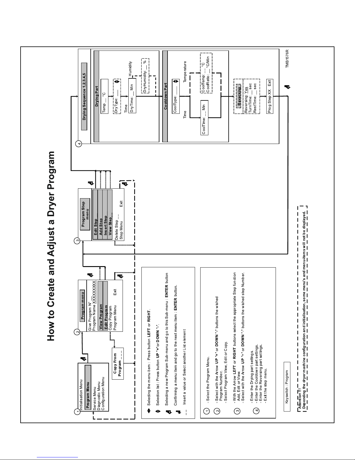
Initializing the Machine
How to Create and Adjust a Dryer Program
©
Copyright, Alliance Laundry Systems LLC -
DO NOT COPY or TRANSMIT
22 Part No. D1621ENR3
Page 23
Programming
Programming
General
Specific functions have been implemented in the FLEX CONTROL dryer computer to allow a detailed programming.
Functions for the complete program.
• Program Number : Selecting the dryer Program
• Program Name : Creating the Program Name
• View : Inspecting the Program settings without making
changes
• Edit : Adjusting a Program
• Copy : Making a Copy of an existing Program
• Exit : Leave the Program Menu
Functions for the program steps.
• Step Number : Selecting the Program Step
• Edit : Adjusting the Program Step
• Add : Adding a Program Step at the end of the program
• Insert : Inserting a Program step in between other Program
Steps
• View : Inspecting the Step settings without making changes
• Delete : Deleting a Step
• Exit : Leave the Program Step Menu
Follow the flowchart step by step.
Step 2: Program Functions
SELECT THE PROGRAM NUMBER
P:Give Program Number : _ _
VIEW A PROGRAM
P: Program N°XX
View
• Select the desired program
number by pressing the
ARROW UP or DOWN
button.
• Program 1 to 20 can be selected.
• Press the ENTER button as
a confirmation.
• In Program View you can
look to the Program Settings, without making
changes.
• Press the ARROW RIGHT
button if you don‘t want to
see the program OverView.
• Press the ENTER button if
you want to see the program Over-View.
Step 1: Program Menu
HOW TO GET INTO THE PROGRAM MENU
The initialization menu can only be accessed when the machine is
in standby (the machine is powered up but no program is started).
• SELECT Process_ _ is displayed.
• Switch the programming switch to Program Mode.
• The Main menu is now available.
• Press the ARROW RIGHT button to select the Program
Menu.
Main Menu PROGRAM
• Press the ENTER button to confirm your selection.
• Goto Step 2: Program Functions »
EDIT A PROGRAM
P: Program N°XX Edit
NOTE: In the program
Over-View Menu, at the
end of a Dryer Program
Step, Press the ENTER
button to see the next
step. See also Step 3: Pro-
gram Step Functions »
• Editing a program is
changing the program by
selecting a new element
from a list or by changing
values in an existing program. You can also add, or
delete steps in an existing
program.
• Press the ARROW RIGHT
button if you don‘t want to
Edit the program.
• Press the ENTER button if
you want to Edit the program. Goto Step 3: Pro-
gram Step Functions »
©
Copyright, Alliance Laundry Systems LLC -
DO NOT COPY or TRANSMIT
23 Part No. D1621ENR3
Page 24
Programming
COPYING A PROGRAM
P: Program N°XX
Copy
P: Copy from Program
N° _ _ _
EXIT THE PROGRAM MENU
P: Program Menu Exit
• If you want to adjust a new
program, sometimes it’s
easier to make a copy of an
existing program and to
make some small changes
to your new copy.
• Press ARROW RIGHT
button if you don‘t want to
Copy a program.
• Press the ENTER button if
you want to make a copy
from another program.
• A confirmation is asked to
delete the old program. P:
Delete Old Program? No
• Press the ENTER button if
you don‘t agree to copy the
old program. Goto Step 1:
Program Menu »
• Press YES and ENTER
button to confirm if you
want to implement a new
program.
• Insert the desired program
number from which you
want to copy the program.
• Press the ENTER button as
a confirmation. Goto Step
1: Program Menu »
• Press the ENTER button if
you want to leave the PROGRAM Menu.
Step 3: Program Step Functions
EDIT A STEP
P:Edit Step : _ _
ADDING A STEP AT THE END OF THE PROGRAM
P:Add Step
INSERTING A STEP BETWEEN EXISTING STEPS
• If you edit a step, you will
change values or list elements from an existing
step.
• Press the ARROW RIGHT
button if you don‘t want to
Edit a step.
• Select the Step number. If
the number is not accepted,
this means that the step is
not available.
• Press the ENTER button to
confirm your selection.
Goto Step 4: Programming
the Drying Part »
• Default programs have only 1 step. For more complicated programs, you can
add 4 extra steps. New
steps are added at the end
of the program.
• Press the ARROW RIGHT
button if you don‘t want to
Add a new step.
• Press the ENTER button if
you want to add a new
step. Goto Step 4: Pro-
gramming the Drying
Part »
NOTE: With the ARROW
LEFT button you can go
back to a previous menu
item.
©
Copyright, Alliance Laundry Systems LLC -
DO NOT COPY or TRANSMIT
P:Insert Step : _ _
• Default programs have only 1 step. For more complicated programs, you can
add 4 extra steps. Steps are
inserted in between other
steps. The steps with the
same or higher number will
be increased with 1.
• Press the ARROW RIGHT
button if you don‘t want to
Insert a new step.
• Press the ENTER button if
you want to Insert a new
step. Goto Step 4: Pro-
gramming the Drying
Part »
24 Part No. D1621ENR3
Page 25
Programming
VIEW A STEP
P:View Step : _ _
DELETE A STEP
P:Delete Step : _ _
EXIT STEP MENU
• Before making changes in
a dryer program, it‘s recommended to have a look
at the actual settings by the
view function.
• Press the ARROW RIGHT
button if you don‘t want to
View a step.
• Select the Step number. If
the number is not accepted,
this means that the step is
not available.
• Press the ENTER button to
confirm your selection.
Goto Step 4: Programming
the Drying Part »
NOTE: Step 1 can not be
deleted.
• If you delete a step, an existing step in the program
will disappear.
• Press the ARROW RIGHT
button if you don‘t want to
DELETE a step.
• Select the Step number.
• Press the ENTER button to
confirm your selection. If
the number is not accepted,
this means that the step is
not available.
• A confirmation is asked to
delete the old step. P: Delete Old Step? No
• Press the ENTER button if
you do NOT want to delete
the old step.
• Press YES and ENTER
button to confirm if you
want to delete a step. Goto
Step 3: Program Step
Functions »
P:Step Menu Exit
• Press the ENTER button if
you want to leave the PROGRAM STEP Menu.
NOTE: With the ARROW
LEFT button you can go
back to a previous menu
item.
Step 4: Programming the Drying Part
This paragraph gives a detailed explanation about programming the Dryer Sequences.
• Each program step contains a drying part and a cooldown
part.
• First the dryer part must be selected, item by item can be programmed.
• Next the cooldown part must be selected, item by item can be
programmed. See Cool-Down Function ».
• Without making changes you can watch item by item, by
pressing the ARROW RIGHT or LEFT button.
• If you want to make changes :
• Adjust a value by pressing the ARROW UP „+“ or
DOWN „-“ button
• Enable or disable a Setting by pressing the ARROW UP
„Yes“ or DOWN „No“ button.
• Select a list element by pressing the ARROW UP
„Next“ or DOWN „Previous“ button.
• Each time you add a new step, default values have been preprogrammed. So with less effort, complete programs can be
programmed. See also chapter Basic description of controls
for a general explanation concerning the creation of dryer programs.
• You can recognise a list element by the „ARROW UP &
DOWN“ symbol at the right side on the display.
• Press the ARROW RIGHT button to go to the last Menu
Item : EXIT.
THE DRY SEQUENCE
P:Pr XX Step XX
Temp : 45 °C
°C : degrees Celsius
°F : degrees Fahrenheit
• The temperature can be
programmed between 1°C
and 70°C.
• 45°C is the suggested default value.
• Adjust the desired temperature. Press the ENTER button for confirmation.
©
Copyright, Alliance Laundry Systems LLC -
DO NOT COPY or TRANSMIT
25 Part No. D1621ENR3
Page 26
Programming
P:Pr XX Step XX
DryType : Time
P:Pr XX Step XX
DryTime : _ _
P:Pr XX Step XX
DryHumidity : _ _ %
• 2 types of dry sequence can
be selected.
1. Time controlled se-
quence: The dry sequence will stop after
the specified period of
time.
2. Sequence controlled by
time and residual moisture (only applies to
machines fitted with a
humidity sensor): The
dry sequence will stop
after the specified period of time or after the
specified laundry residual moisture has been
reached.
• By the ARROW UP and
DOWN button you can select the required setting.
Press the ENTER button
for confirmation.
• The Dry Time is the programmed time that the linen is dried by forced heating.
• The default value is 30 minutes.
• The value is programmable
between 0 and 120 minutes.
• Adjust the desired Drytime. Press the ENTER
button for confirmation.
• The DryHumidity value is
the programmed value for
which the dry process is
stopped when the target residual moisture in the linen
has been reached. (Dried
by forced heating.)
• The default value is 5 %.
• The value is programmable
between 0 and 30 %.
(50-70% is the residual
moisture level after extraction in washing machine.)
• Adjust the desired Humidity level. Press the ENTER
button for confirmation.
P:Pr XX Step XX
CoolType : Time
P:Pr XX Step XX
CoolTime : _ _ Min
P:Pr XX Step XX
CoolTemp : _ _ °C
• 2 types of CoolDown sequence can be selected.
The Cooldown sequence
will be stopped at :
• a preset Cooldown
time.
• a preset Temperature
value
• By the ARROW UP and
DOWN button you can select the required setting.
Press the ENTER button
for confirmation.
• The Cooldown Time is the
programmed time for
which the dryer is cooling
the fabrics. (Heating is
switched Off).
• The default value is 5 minutes.
• The value is programmable
between 0 and 120 minutes.
• Adjust the desired Cooldown Time. Press the ENTER button for confirmation.
• The Cooldown Temperature is the programmed
temperature for which the
dryer is cooling the fabrics.
(Heating is switched Off)
• The default value is 40 °C.
• The value is programmable
between 0 and 70 °C.
• Adjust the desired Cooldown Temperature. Press
the ENTER button for confirmation.
©
Copyright, Alliance Laundry Systems LLC -
DO NOT COPY or TRANSMIT
26 Part No. D1621ENR3
Page 27
Programming
P:Pr XX Step XX
CoolRatio : _ _
P:Pr XX Step XX
Reversing : Yes
• For special applications, a
controlled cooldown sequence is required.
• The temperature will decrease in small steps in relation to the time. The ratio
for the cooldown sequence
is the temperature in function of time.
• The default value is 0 °C/
Min.
• The value is programmable
between 0 and 5 °C/Min.
• Adjust the desired Cooldown Ratio. Press the ENTER button FOR CONFIRMATION.
Only for machines executed
with reversing.
• Reversing can be switched
Off and On.
• The default value is Yes.
• By the ARROW UP and
DOWN button you can select the required setting.
Press the ENTER button
for confirmation
P: Program Step XX
Exit
• You can always return to a
previous menu item by
pressing the ARROW
LEFT button.
• By pressing the ENTER
button you will leave the
current Step. Goto Step 3:
Program Step Functions »
P:Pr XX Step XX
TurnTime : _ _ sec
P:Pr XX Step XX
RestTime : _ _ sec
Only for machines executed
with reversing.
Settings are applicable for
the DRY and COOLDOWN
part of the Step.
• A reversing Motor On/Off
time can be programmed.
• Depending the kind of fabrics, a short or long reverse
time is applicable.
• Default values: 40 sec On
and 5 sec Off time.
• Programming limits:
• On: 3 - 120 sec
• Off: 1 - 15 sec
• Adjust the desired Motor
On and Off times. Press the
ENTER button for confirmation.
©
Copyright, Alliance Laundry Systems LLC -
DO NOT COPY or TRANSMIT
27 Part No. D1621ENR3
Page 28
Operation menu
Operation menu
Start Up
WARNING
BEFORE STARTING UP THE FIRST TIME, BE SURE
THAT THE MACHINE IS WELL INSTALLED. SEE INSTALLATION AND MAINTENANCE MANUAL. MAKE
SURE THAT THE CONFIGURATION AND INITIALIZATION MENU HAVE THE RIGHT SETTINGS. SEE
CHAPTER INITIALIZING THE MACHINE.
WARNING
DRY CYCLES CAN ONLY BE STARTED WHEN THE
PROGRAMMING SWITCH IS IN RUN MODE.
Switch On the Power
The display lights up when the power is turned on.
• If the program is ready to be started, Select Process _ _ is displayed.
Load the Dryer
• first you will see the Dryer Sequence
• then you will see the Cooldown Sequence
• A row of bars, shows you if the Sequence has just been started or if ¼, ½ or ¾ of the Sequence time is over.
PrXX StYY ZZ.Z Min
Dry
PrXX : The selected program number.
StYY : The selected program Step.
C129
C130
ZZ.Zmin or ZZ.Z H : The remaining program time in 1/10 of Minutes or 1/10 of Hours.
: A row of bars appears as a function of the remaining
sequence time.
Dry : The executed Sequence. (example, Dry)
Advancing a Dryer Program
» Press the ARROW UP button to increase the dry-cooldown sequence time.
» Press the ARROW DOWN button to decrease the dry-cooldown sequence time.
» Press the START button to skip the current step. >> >> is displayed instead of the remaining time at the moment that the step
is skipped.
Open the door and load laundry into the drum. When the drum is
loaded, close the door.
Start a Dryer Program
» Create a simple program by the special function buttons on the
keypad.
• Press the ARROW UP and DOWN buttons to adjust the corresponding values.
» Or Select the program number by the PROGRAM SELECT
button.
• Up to 20 programs can be selected. The first 9 are the standard Drying programs you can find in this manual.
» Press the „START“ button.
The Active Program
• The cycle time will decrease minute by minute and gives you
an indication how long it will take before the cycle is finished.
• For each Dryer program Step :
WARNING
Even if the advance function has been switched off
in the initialization menu, the advance function will
work if the programming switch is turned into program mode.
C066
Drying Time
Once the program has been started, the remaining dry time is displayed in minutes.
Program End
1. The "0" on the display will be erased and the machine is ready
to start a new program.
2. Once the program cycle is finished, UNLOAD is displayed.
3. Open the door and unload the machine.
• The Message UNLOAD will be erased and the machine is
ready to start a new program.
• SELECT PROCESS _ _ is displayed.
©
Copyright, Alliance Laundry Systems LLC -
DO NOT COPY or TRANSMIT
28 Part No. D1621ENR3
Page 29
Operation menu
Cool-Down Function
• For Safety purposes the machine will always execute a cooldown sequence at the end of the drying cycle. (Programmed
dry temperature > 50°C). Even if the cooldown time has been
put on 0 minutes in the program menu.
Stop
• By pressing the STOP button the program is interrupted.
• First the machine will go over to a safe state.
• Then the message CONTINUE ? is displayed.
» STOP : the program is stopped.
» START : the program goes on with the rest of the cycle.
Wait State
Normal machine operation can be interrupted. You have to wait
until the FLEX CONTROL Dryer Computer allows you to go on.
You can recognize the wait state by a display that shows WAIT
and a decreasing counter.
This will occur when the power has been switched off and on at a
running dry cycle.
A delay time is respected before the machine can be restarted.
• The message UNLOAD ! will inform you if it‘s allowed to
open the door.
Safety conditions
• If the actual temperature is too high the message „TOO
HOT“ will be displayed together with the actual temperature.
WARNING
Go to the chapter Troubleshooting to find out more
about error handling.
C070
How to Handle Power Interruptions
When a power interruption occurs while the machine is in standby mode, and no program cycle was started, the machine will
stay in standby mode.
When a power interruption occurs while the dry or cooldown sequence is busy, after the power interruption, the message Continue ? will be displayed.
» STOP : the program is stopped.
» START : the program goes on with the last active step until the
end of the program.
How to Handle Failure Messages
NOTE: For more information about error messages refer to Error Handling.
• When a failure has been detected by the FLEX CONTROL
Dryer Computer, a failure message is generated, to inform the
operator about the problem.
PrAA StBB Unload !
EXXX:YYYYYYYYYYYY
AA : The Program number
BB : The Step number
Unload ! : If it is allowed to open the door, the message Unload is
displayed
E XXX : The error number
YYYYYYYY : The name of the error message
• At the upper left corner, the program number and step number
of the interrupted program are displayed.
Service-State Button
• The Service button is dedicated to supply the operator with
more information about the dryer machine functions.
» Press the SERVICE-STATE button if you want to inspect the
actual temperature and humidity level.
• At the Service - State menu, you can inspect :
• the dryer temperature and humidity level
• the number of cycles that have been accumulated (service
due)
• the actual dryer machine states at the running dry cycle
• By switching the programming switch to Program Mode, the
Service-State menu will not disappear after 1 minute.
• By pressing the ARROW RIGHT button you will see all the
menu items.
• You can leave the Service - State menu by pressing the SERVICE-STATE button again.
©
Copyright, Alliance Laundry Systems LLC -
DO NOT COPY or TRANSMIT
29 Part No. D1621ENR3
Page 30
Operation menu
Humidity Control
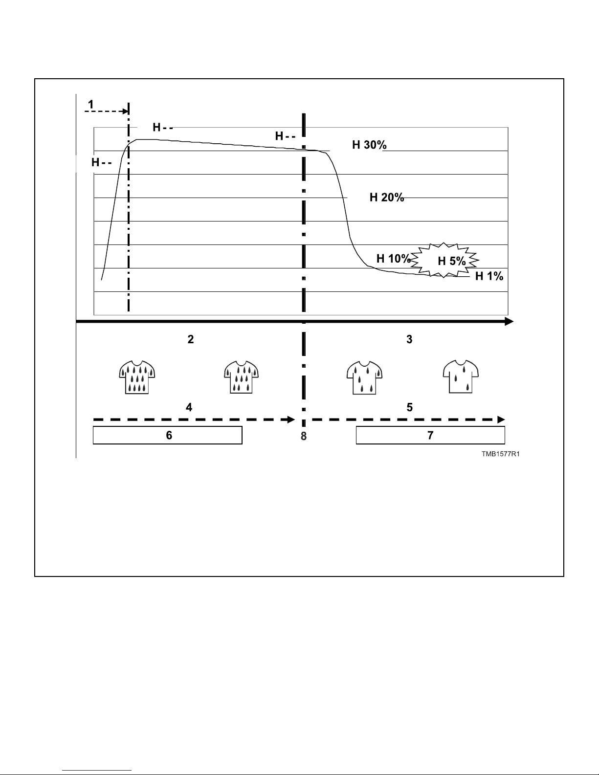
Residual Humidity Linen
1. Heating up
2. Linen is wet
3. Linen is dry
4. Part 1: RH > 30%
5. Part 2: RH < 30%
6. H -- shown on display
7. H XX shown on display
8. Dry cycle time
At the drying process with humidity control, the air humidity is
measured by an absolute air humidity sensor. The graph shows
the absolute air humidity in function of time. When a drying cycle is started, the air humidity will go up quickly as the heating
system starts up, then the air humidity will decrease bit by bit.
The dryer computer humidity sensor measures this value and calculates the corresponding residual humidity of the linen. The residual humidity is the remaining amount of water in wet linen
©
Copyright, Alliance Laundry Systems LLC -
DO NOT COPY or TRANSMIT
Figure 4
compared with it's dry equivalent. When the linen is taken out a
washing machine:
• A high extraction speed results in about 50 % residual humidity
• A low extraction speed results in about 70 % residual humidity
At the drying cycle (humidity control) the display shows :
• H - - : The residual humidity is above 30 % (the linen is wet)
30 Part No. D1621ENR3
Page 31
• H XX : The residual humidity value is below 30% (the linen
gets dry)
Above 30% residual humdity, the linen is so wet that there is no
accurate measurement. For this reason there is not shown a value
on the display, just two dashes. It can take 10 to 40 minutes, depending the amount of load and how wet the linen is, before the
Residual Humidity Value is shown on the display.
The default programmed value for residual humidity of linen is
5%.
IMPORTANT: While the dryer is running, do not open
and close the door, it disturbs the humidity control
measurement.
WARNING
CERTAIN FABRICS CAN GET DAMAGED WHEN
DRYED UNTIL A RESIDUAL HUMIDITY OF 0%.
(BONE DRY). CERTAIN FABRICS GET ELECTROSTATIC CHARGED FOR A RESIDUAL HUMIDITY BELOW 5% (WHICH SHOULD BE AVOIDED).
Operation menu
C132
WARNING
THE HUMIDITY CONTROL SYSTEM IS NOT MADE TO
RUN WITHOUT LOAD OR WITH A VERY SMALL
LOAD. THE SYSTEM CAN ONLY FUNCTION IN A
NORMAL WAY WHEN THERE IS SUFFICIANT EVAPORATION TO BE MEASURED BY THE AIR HUMIDITY
SENSOR.
C133
©
Copyright, Alliance Laundry Systems LLC -
DO NOT COPY or TRANSMIT
31 Part No. D1621ENR3
Page 32
Pre-programmed programs
Pre-programmed programs
General
The FLEX CONTROL Dryer Computer contains 9 pre-programmed Standard Dryer Programs.
WARNING
THE PRE-PROGRAMMED PROCESSES ARE GIVEN
AS AN EXAMPLE ONLY. FOR THE CREATION OF
YOUR OWN PROGRAMS, CHECK THE PROPERTIES
OF THE FABRICS AND THE RESIDUAL MOISTURE
AFTER THE DRYING PROCESS.
Drying Programs
Program 1: COLD 20 MIN
Sequence Tempera-
ture.
Step1Drying - - A = 40
Cooldown - 20
Time (minutes)
Reversation (seconds)
R = 5
C134
Program 4: MEDIUM 104°F [40°C] 40 MIN
Step1Drying 104°F
[40°C]
Cooldown - 4
40 A = 40
R = 5
Program 2: LOW 86°F [30°C] 20 MIN
Sequence Tempera-
ture.
Step1Drying 86°F
[30°C]
Cooldown - 3
Program 3: LOW 95°F [35°C] 30 MIN
Sequence Tempera-
ture.
Step1Drying 95°F
[35°C]
Cooldown - 3
Program 4: MEDIUM 104°F [40°C] 40 MIN
Sequence Tempera-
ture.
Time (minutes)
20 A = 40
Time (minutes)
30 A = 40
Time (minutes)
Reversation (seconds)
R = 5
Reversation (seconds)
R = 5
Reversation (seconds)
©
Copyright, Alliance Laundry Systems LLC -
DO NOT COPY or TRANSMIT
Table continues...
32 Part No. D1621ENR3
Page 33
Pre-programmed programs
Program 5: MEDIUM 113°F [45°C] 30 MIN
Sequence Tempera-
ture.
Step1Drying 113°F
[45°C]
Cooldown - 4
Program 6: MEDIUM 122°F [50°C] 40 MIN
Sequence Tempera-
ture.
Step1Drying 122°F
[50°C]
Cooldown - 5
Program 7: HOT 140°F [60°C] 30 MIN
Sequence Tempera-
ture.
Time (minutes)
Reversation (seconds)
30 A = 40
R = 5
Time (minutes)
Reversation (seconds)
40 A = 40
R = 5
Time (minutes)
Reversation (seconds)
Program 8: HOT 149°F [65°C] 40 MIN
Step1Drying 149°F
[65°C]
40 A = 40
R = 5
Cooldown - 5
Program 9: HOT 158°F [70°C] 30 MIN
Sequence Tempera-
ture.
Step1Drying 158°F
[70°C]
Time (minutes)
Reversation (seconds)
30 A = 40
R = 5
Cooldown - 5
Program 10: HOT X °F [°C] MIN
Sequence Tempera-
ture.
Time (minutes)
Reversation (seconds)
Step1Drying X°F [°C] 30 A = 40
Cooldown - 5
R = 5
Step1Drying 140°F
[60°C]
Cooldown - 5
Program 8: HOT 149°F [65°C] 40 MIN
Sequence Tempera-
ture.
30 A = 40
R = 5
Time (minutes)
Reversation (seconds)
All models: X = 158°F [70°C]
Program 11: HOT X °F [°C] 30 MIN
Sequence Tempera-
ture.
Time (minutes)
Step1Drying X °F [°C] 30 A = 40
Cooldown - 5
Table continues...
All models: X = 70°C
REVERSATION
• A = 40 seconds = 40 Seconds Action (Drum Turns)
• R = 5 seconds = 5 Seconds Rest (Drum is at Standstill)
Program 12: Wool
Sequence Temperature Humidity (%) Time (minutes)
Step 1 Drying 107.6°F [42°C] 20 - -
Cool Down - - - -
Reversation (seconds)
R = 5
Reversation
(seconds)
Step 2 Drying 105.8°F [41°C] 4 - -
Cool Down - - - -
©
Copyright, Alliance Laundry Systems LLC -
DO NOT COPY or TRANSMIT
Table 2 continues...
33 Part No. D1621ENR3
Page 34
Pre-programmed programs
Program 12: Wool
Sequence Temperature Humidity (%) Time (minutes)
Step 3 Drying 104°F [40°C] - 15 -
Cool Down - - - -
Table 2
Program 13: Silk
Sequence Temperature Humidity (%) Time (minutes)
Step 1 Drying 104°F [40°C] 25 - -
Cool Down - - - -
Step 2 Drying 102.2°F [39°C] 5 - -
Reversation
(seconds)
Reversation
(seconds)
Cool Down - - - -
Step 3 Drying 96.8°F [36°C] - 6 -
Cool Down - - - -
Table 3
Program 14: All In One
Sequence Temperature Humidity (%) Time (minutes)
Step 1 Drying 109.4°F [43°C] 20 - -
Cool Down - - - -
Step 2 Drying 107.6°F [42°C] 4 - -
Cool Down - - - -
Step 3 Drying 105.8°F [41°C] - 15 -
Cool Down - - - -
Table 4
Reversation
(seconds)
©
Copyright, Alliance Laundry Systems LLC -
DO NOT COPY or TRANSMIT
34 Part No. D1621ENR3
Page 35
Pre-programmed programs
Program 15: Delicate Items
Sequence Temperature Humidity (%) Time (minutes)
Step 1 Drying 100.4°F [38°C] 20 - -
Cool Down - - - -
Step 2 Drying 96.8°F [36°C] 10 - -
Cool Down - - - -
Step 3 Drying 105.8°F [41°C] - 15 -
Cool Down - - - -
Table 5
Program 16: No Heating
Sequence Temperature Humidity (%) Time (minutes)
Reversation
(seconds)
Reversation
(seconds)
Step 1 Drying 95°F [35°C] - 10 -
Cool Down - - - -
Table 6
©
Copyright, Alliance Laundry Systems LLC -
DO NOT COPY or TRANSMIT
35 Part No. D1621ENR3
Page 36
Troubleshooting
Troubleshooting
Display Messages
• Various messages may appear on the display at the start, during or at the end of a drying cycle.
• In some specific cases, an acoustic signal will alert the operator.
• When an error occurs the machine will automatically go over
to a safe state.
Fault Messages
• If a failure occurs, the computer will display a diagnostic error message.
• The program number and step at which the interruption has
occurred are displayed.
• The fault message itself contains a number and a corresponding text label by which it’s easy to find the related information
in the manual.
• If Unload ! is displayed, it’s allowed to open the door.
PrXX StYY Unload !
EZZZ: Fault message
XX : the program number
YY : the program step number
• If at the end of the cycle the safety conditions are not fulfilled
(Temperature > 50°C), the message TOO HOT will be displayed. (TOO HOT MESSAGE IS ERASED BY OPENING
THE DOOR, A NEW SEQUENCE CAN BE STARTED)
TOO HOT
XX °C
• If the problem disappears, (the temperature has dropped below 50°C) the Error message TOO HOT will disappear automatically.
WARNING
IT’S UP TO THE OPERATOR TO TAKE THE NECESSARY PRECAUTIONS FOR HIGH TEMPERATURES
OF FABRICS AND TUB WHEN THE DRYER DOOR IS
OPENED. ON THE DISPLAY THE ACTUAL TEMPERATURE IS DISPLAYED. BEFORE ALL INTERVENTIONS, TO PREVENT BURNS WAIT UNTIL THE HOT
PARTS HAVE COOLED.
C136
WARNING
Unload ! : open the door if Unload ! is displayed
EZZZ : the number of the occurred error
Fault message : the text label of the error message
How to Handle Fault Messages
WARNING
Check in the manual to see what problem the error
message corresponds with. Ask the assistance of an
experienced technician to solve the problem. All the
safety precautions must be followed before each intervention.
• You can overrule and erase fault messages by:
• Pressing the STOP or ENTER button (programming
switch in program mode)
• Switching the power off/on
• Opening the door (Ignition Error, Air Flow Switch)
• Each time at the end of the cycle, the FLEX CONTROL Dryer computer will fulfil a cooldown sequence (Actual temperature > 50 °C).
C075
THE ERROR MESSAGE TOO HOT CAN ALSO APPEAR AT THE END OF A CYCLE EVEN IF NO FAILURE HAS OCCURED AS AN EXAMPLE, DRYING CYCLE WITH A SHORT COOLDOWN TIME. AT THE END
OF SUCH A DRYING CYCLE, THE TEMPERATURE IN
THE TUB WILL STAY HIGH FOR A WHILE IF THE
COOLDOWN SEQUENCE WAS TOO SHORT. THE
CONTROL DRYER COMPUTER WILL GIVE A WARNING THAT THE TEMPERATURE IS STILL HIGH.
C137
DEPENDING ON THE FAILURE TYPE THE FLEX CONTROL COMPUTER WILL START A SPECIFIC PROCEDURE :
• WHEN SAFETY IS INVOLVED
• Full stop : the program is stopped.
• Full stop + cooldown : the program is stopped but a cooldown sequence is started.
• Don’t start : the program will not be started as long as the
safety conditions are not fulfilled.
• WHEN SAFETY IS NOT INVOLVED
• Full stop + request for continue : a request to Continue ?
the program is displayed.
©
Copyright, Alliance Laundry Systems LLC -
DO NOT COPY or TRANSMIT
36 Part No. D1621ENR3
Page 37
Troubleshooting
• Skip + continue : the actual cycle step is skipped and the
program continues with the next step.
• Continue : the program continues.
SPECIAL CASES :
• For E19, 20: Defective Temperature sensor and E35: Wrong
software version The Failure message can only be erased by
switching the power off and back on.
• Fault 41: Service Due will occur over and over again until
you have reset the cycle counter. See Paragraph Overview
how to reset the cycle counter.
RESET KEY :
• When you have overruled an error message and opened the
door, Reset Key will be displayed.
• This message warns the operator that the programming switch
is still in Program mode.
• Before you can start a new program you have to switch the
programming switch back to Run mode.
! ! Reset Key ! !
» Switch the programming switch to Run mode.
MESSAGE “CLOSE THE LINT FILTER DOOR”
• This message indicates that the lint filter door is open during
machine operation.
Overview
• Close the lint filter.
• If the message keeps showing even after the door has been
closed, check the power feed of the controller board and the
fuses.
Clean Filter
UNLOAD CLEAN FILTER
• It’s a good attitude to clean the Lint Filter each day. (See also
Installation and maintenance manual).
• As safety is involved, when the Lint Filter has not been
cleaned sooner then 15 succeeding cycles, a warning will be
displayed at the end of the drying cycle. „CLEAN FILTER“
• As the amount of lint depends on the kind of fabrics it’s possible to adjust the number of cycles, for which the warning is
generated, in the Configuration menu.
• Only by opening the lint door the Lint Filter Door Cycle
Counter will be reset.
• By opening the Dryer Door the warning on the display is
erased but the Lint Filter Door Cycle Counter is not reset.
• You can check the Lint Filter Door Cycle Counter at the Running State-Service Menu which is accessible by the special
function button on the keypad. (Press ARROW RIGHT button to go to the next menu item.) (Only valid for machines
executed with an electric contact at the Lint Door)
N° Failure Message Failure Action Fault Occurrence
E1 Heating Safety 1 Heated air too hot Heating Off, Full Stop at
Whole cycle
safe temperature
E2 Heating Safety 2 Heater too hot Heating Off, Full Stop at
Whole cycle
safe temperature
E3 (1) PresSensLow Low pressure in the heat
pump circuit
E4 (1) PresSensHigh High pressure in the heat
pump circuit
E5 Motor Thermic Motor Security Trips Heating Off, Full Stop at
Heating Off, Full Stop at
safe temperature
Heating Off, Full Stop at
safe temperature
Whole cycle
Whole cycle
Motor contactor on
safe temperature
E6 Fan Motor Thermic Fan Motor Security Trips Heating Off, Full Stop at
Motor contactor on
safe temperature
E7 Drum Motor Thermic Drum Motor Security Trips Heating Off, Full Stop at
Motor contactor on
safe temperature
E8 Airflow switch Open at
Startup
Airflow switch at start-up Heating OffFull Stop at
safe temperature
At Start-up
Table continues...
©
Copyright, Alliance Laundry Systems LLC -
DO NOT COPY or TRANSMIT
37 Part No. D1621ENR3
Page 38
Troubleshooting
N° Failure Message Failure Action Fault Occurrence
E9 Airflow switch Open after
Startup
E10 Airflow switch Closed Airflow switch failure be-
Airflow switch after startup Heating OffFull Stop at
safe temperature
Don’t start At Start-up
Whole Cycle after Start-up
fore start-up
E11 Fault Cool down No temperature drop at cool
Heating Off, At Cool down sequence
down
E12 No Reheating Heating not restarted Heating Off, At Heating sequence
E13 No Heating Heating failure Heating Off, At Heating sequence
E14 Heat Time Heating time failure Heating Off, At Heating sequence
E15 Too Hot Too Hot Heating Off, Full Stop at
At Heating sequence
safe temperature
E16 Coin Blocking 1 / / /
E17 Coin Blocking 2 / / /
E18 Too Hot Safety Temp. too high (risk of
burn!)
Heating Off, Full Stop at
safe temperatureMajor
Before Start-up
Alarm
E19 Defective Temperature sen-
Value out of range Continue + Don’t start Before Start-up
sor 1
E20 Defective Temperature sen-
Value out of range Continue + Don’t start Before Start-up
sor 2
E21 Heating element overheat-
ing
E25 No Humidity Sensor Humidity Sensor not con-
E26 No Humidity Sensor Cap Cap Humidity Sensor miss-
E27 No Humidity Reduction Time out no reduction hu-
E28 Lint Filter Lint Filter has not been
Safety Heating element
trips
nected
ing
midity value
Heating Off, Full Stop at
Whole cycle
safe temperature
Continue, for info only
Whole cycle
saved in Err log.
Continue, for info only
Whole cycle
saved in Err log.
Heating Off, Full Stop at
Whole cycle
safe temperature
Don’t start At Start Up
opened for 40 cycles
E29 TimeOut Cool No Cool down Heating Off, Full Stop at
At Cool down
safe temperature
E35 Wrong Softw Wrong software version Don’t start New software version
E37 Too Hot Safety Temp. too high (risk of
burn!)
E39 (1) Error Fan Contact of fan motor elec-
tronic protection discon-
Major Alarm + Extra Cool
down Time
Heating Off, Full Stop at
safe temperature
Whole cycle
Whole cycle
nected
©
Copyright, Alliance Laundry Systems LLC -
DO NOT COPY or TRANSMIT
Table continues...
38 Part No. D1621ENR3
Page 39
Troubleshooting
N° Failure Message Failure Action Fault Occurrence
E40 (1) PhaseErr Faulty sequence (order) of
phases or interruption /
drop of phase voltage in the
Heating + motor-drive Off,
Full Stop at safe temperature
Whole cycle
power supply system
E41 Service Due Service Due Warning For Info only Open door =
End cycle
reset
E150-E165 Memory Err Memory Error Full stop + safety time Any time
E170-E199 Softw Err Software Error Full stop + safety time Any time
(1) machine with heat pump (HP)
Service Menu
In the Service menu you have some extra utilities:
• The Software Version Number
• An overview of the 8 last failure messages
• Statistics for general occurence of error messages
• An overview of the input states
• Reset Cycle Counter and Statistics Error Messages
HOW TO GET INTO THE SERVICE MENU
The SERVICE menu can only be accessed when the machine is
in standby (the power is switched on, but no program is started).
• SELECT Process_ _ is displayed.
• Switch the programming switch to Program Mode.
• The Main menu is now available.
• Press the ARROW RIGHT button to select the SERVICE
menu.
S:Fault N° 1 :
EXXX:YYYYYYYY
YY
• There are 8 Fault Messages
kept in EEPROM memory.
• Fault N° 1 : the last oc-
• Fault N° 2 : the last –1
• …
• Fault N° 8 : the last – 7
• E XXX : The Error message number.
• YYYYYYYYYY : The Error message name.
• Press the ARROW RIGHT
button to see message by
message and to leave the
Error message menu.
• If no messages are displayed, this means that no
Errors have occurred.
Main Menu Service
• Press the ENTER button to make your selection.
• Now you will see the first menu item.
• By pressing the ARROW LEFT or RIGHT button you can see
the menu items one by one.
S:Software Version
1.00
• The Software Version number.
S:Erase Fault Messages? No
• If you don‘t want to erase
the Fault messages, press
the ARROW RIGHT button.
• Press the YES and ENTER
button if you want to erase
the Error messages.
• You can select the next
menu item by pressing the
ARROW RIGHT button.
curred error message.
occurred error message.
occurred error message.
S:View Fault Messages?
• If you don‘t want to see the
Fault messages, press the
ARROW RIGHT button.
• If you want to see the Fault
messages, press the ENTER button.
©
Copyright, Alliance Laundry Systems LLC -
DO NOT COPY or TRANSMIT
39 Part No. D1621ENR3
Page 40
Troubleshooting
S:View Fault Statistics?
S:Heating Safety 1
0 x
S:View Input States ?
• If you don‘t want to see the
Fault statistics, press the
ARROW RIGHT button.
• If you want to see the Fault
statistics, press the ENTER
button.
• The Fault Statistics are an
accumulation of Errors
messages that have appeared over a long period.
• The Statistics can be reset
at the Service Menu, by a
Reset of the Cycle counter.
• With this information the
technician has an indication on which parts an intervention will be needed.
• The List with Statistics.
• Heating Safety 1 : E1
• Heating Safety 2 : E2
• Motor Thermic : E5 + E6 +
E7
• Air Flow Switch : E8 + E9
+ E10
• Fault Cooldown : E11
• No Heating : E12 + E13 +
E14
• Too Hot : E15 + E18
• Temperature Sensor : E19
+ E20
• If you don‘t want to see the
Input States, press the ARROW RIGHT button.
• If you want to see the Input
States, press the ENTER
button.
S:Input 1 Off/On
S:Reset Cycle Counter : No
• Input 1 : the State that corresponds with Input 1.
• Input 2 : the State that corresponds with Input 2.
• …
• Input 20 : the State that
corresponds with Input 20.
• Analog Input 1, 2, 3 : the
value that corresponds with
Analog Input 1, 2, 3.
• The exact function of the
inputs can be found on the
electrical drawing of the
FLEX CONTROL Dryer.
• If the Input state is Off, the
Input signal is low.
• If the Input state is On, the
Input signal is high.
• Press the ARROW RIGHT
button to see message by
message and to leave the
Input state menu.
• To avoid that No maintenance will be fulfilled
when the machine has
reached the number of cycles that corresponds with
the „Service Interval _ _
_“ number at the Initialization menu, a warning will
be generated over and over
again at the end of each cycle until the Cycle Counter
at the Service menu has
been reset.
• Also the Statistics for Error
messages will be Reset by
resetting the Cycle counter.
• If you don‘t want to reset
the Cycle Counter, press
the ARROW RIGHT button.
• Press the ARROW UP
„Yes“ and ENTER button
if you want to reset the Cycle Counter.
©
Copyright, Alliance Laundry Systems LLC -
DO NOT COPY or TRANSMIT
40 Part No. D1621ENR3
Page 41
Troubleshooting
S: Service Menu Exit
• Press the ENTER button if
you want to leave the
SERVICE Menu.
NOTE: With the ARROW
LEFT button you can go
back to a previous menu
item.
Diagnostic Program
The purpose of the diagnostic program is to test the dryer machine functions one by one.
HOW TO GET INTO THE DIAGNOSTIC MENU
The Diagnostic menu can only be accessed when the machine is
in standby (the power is switched on, but no program is started).
• Select Process_ _ is displayed.
• Switch the programming switch to Program Mode.
• The Main menu is now available.
• Press the ARROW RIGHT button to select the Diagnostic
menu.
Main Menu Diagnostic
• Press the ENTER button to
make your selection.
D:Diagnostic Program : No
S: Diagnostic Menu
Exit
TEST SEQUENCE
• Display test
• Sensor test
• Door test
• Motor test
• Heating test
• If you don’t want to start a
diagnostic program, you
have to press the ARROW
RIGHT button.
• Press the YES and ENTER
button if you want to start
the diagnostic program.
• Press the ENTER button if
you want to leave the Diagnostic Menu.
NOTE: With the ARROW
LEFT button you can go
back to a previous menu
item.
©
Copyright, Alliance Laundry Systems LLC -
DO NOT COPY or TRANSMIT
41 Part No. D1621ENR3
Page 42
Troubleshooting
Problem Check List
Problem Cause Solving the problem
When the power is switched on : the dis-
No external power Switch on the external power supply
play is not illuminated
IMPORTANT: The display must always light up when the power connector is connected to the power
board (EPROM with software must
be implemented)
The emergency stop button is activated Deactivate the emergency stop button
The power connector is not connected on
the board
Check voltage on the power supply connector
The display is illuminated, but it’s difficult
The brightness is not Ok Change the value for Brightness in the
to read the text on the display
The machine is not starting up The programming switch stands in “Pro-
gram mode“
The machine is not responding on pressing
The programming switch is not functional Check if the input connector “A“ is well
the keyboard buttons
verify the external power to the machine
Connect the power connector
Check fuses in the power supply circuits
of the control board. Remove the fuses after the cause of the fault has been rectified
(short circuit / faulty control board).
If there is no EPROM implemented on the
logic board, put the right EPROM with
software into the socket
Configuration Menu until you get a bright
display.
Set the programming switch to “Run
mode“
connected and check the wiring between
the input connector and the programming
switch
The „START“ button is not functional (the
programming switch stands in Program
mode)
No button is functional and the programming switch is in the right position
There is no beep signal when the buttons
are pressed
The machine is not behaving as expected If the wrong machine type is selected the
wrong outputs will be activated
A program is started, but the outputs are
not activated
Wait is displayed and a counter is counting
down
Check if connector “R“ and “S“ are connected
This is a wait state caused by a power interruption or a safety sequence at the end
of the process
set the programming switch to “Run
mode“
Check if the connector “K“ of the keyboard is well connected
Check if the right machine type is selected
in the Configuration Menu.
Connect the connector at the correct position
Door must be closed
Heating safety must be closed
Motor safeties must be closed
Wait until the counter has reached 0
do not switch off/on the power again as
you will restart the counter
Table continues...
©
Copyright, Alliance Laundry Systems LLC -
DO NOT COPY or TRANSMIT
42 Part No. D1621ENR3
Page 43
Troubleshooting
Problem Cause Solving the problem
Unload is displayed and the Door is Open Check if the „Door Switch“ is still closed If the „Door Switch“ is broken, replace the
Door Switch“
The drum is not turning
Check if the belt is broken Check the tension of the belt or replace the
(No error message will be generated if
there is no rotation sensor)
Check the applied motor voltage Repair the motor power supply circuit
Check if the motor is still functional Change the motor if needed
Explanation of Error Messages
Failure 1: Heating Safety 1
Failure 1 occurs when the electronic timer detects that the heating
safety located at the air outlet has opened it’s NC contact.
(NC thermal contact) (failure 1 can only occur when the drying
cycle is running).
A skilled and experienced technician must examine the heating
and air outlet system before the machine is put in operation again.
DIAGNOSE:
1. Check the air outlet system. If the airflow is not sufficient,
adjust the air outlet system.
2. Check the temperature sen-
sor.
3. Check the heating system. If the heating system is broken
4. Check the heating contactor
(valve).
5. Check the wiring. If the wiring is damaged, re-
6. If the heating safety is not
closing within 15 minutes.
If the temperature sensor is not
measuring correctly, replace
the temperature sensor.
repair, replace the heating system.
If the heating contactor (valve)
is not functional repair or replace the component.
pair the wiring.
The heating safety is broken
and must be replaced.
belt
mal contact) (failure 2 can only occur when the drying cycle is
running).
A skilled and experienced technician must examine the heating
and air outlet system before the machine is put in operation again.
DIAGNOSE:
1. Check the air outlet system. If the airflow is not sufficient,
adjust the air outlet system.
2. Check the temperature sen-
sor.
If the temperature sensor is not
measuring correctly, replace
the temperature sensor.
3. Check the heating system. If the heating system is broken
repair, replace the heating system.
4. Check the heating contactor
(valve).
If the heating contactor (valve)
is not functional repair or replace the component.
5. Check the wiring. If the wiring is damaged, repair the wiring.
6. If the heating safety is not
closing within 15 minutes.
7. Check the output relay that
controls the heating system.
The heating safety is broken
and must be replaced.
If the output relay is not functional, replace the control
board.
8. Check the input Signal by
monitoring the state at the
Service menu.
If the input is not functional
anymore, replace the control
board.
7. Check the output relay that
controls the heating system.
If the output relay is not functional, replace the control
board.
8. Check the input Signal by
monitoring the state at the
Service menu.
If the input is not functional
anymore, replace the control
board.
Failure 2: Heating Safety 2
Failure 2 occurs when the electronic timer detects that the heating
safety located at the heater has opened it’s NC contact. (NC ther-
©
Copyright, Alliance Laundry Systems LLC -
DO NOT COPY or TRANSMIT
Failure 3: Pressure Sensor Low
Machine With HEAT PUMP (HP)
Error 3 is displayed when the programmer device finds out that
the pressure in the heat pump circuit has dropped under the safe
level.
DIAGNOSE:
43 Part No. D1621ENR3
Page 44
Troubleshooting
1. Check the pressure in the
coolant circuit.
If the pressure is lower than
the value indicated on the rating table of the pressure
switch, it is possible that the
coolant has leaked out of the
cooling circuit. Repair the
cooling circuit.
2. Check (according to the wiring diagram) whether the cir-
If the wiring is not continuous:
repair the wiring.
cuits have not been interrupted. Check the correct interconnection of the machine with
the heat pump unit.
3. Check the input Signal by
monitoring the state at the
Service menu
If the input is not functional
anymore, replace the pro-
grammer board.
Failure 4: Pressure Sensor High
Machine With HEAT PUMP (HP)
Error 4 is displayed when the programmer device finds out that
the pressure in the heat pump circuit has risen above the safe level.
DIAGNOSE:
1. Check if the lint filter is
clogged or obstructed.
Clean the lint filter.
A skilled and experienced technician must examine the motordrive system before the machine is put in operation again.
DIAGNOSE:
1. Check if the thermal security of the motor is open.
If the thermal security is
open, within 15 minutes the
security will close automatically.
If a motor is defective, the
security can go open again
when you restart the dryer.
If it was only a temperature
problem, and the motor is not
defective: the overload security will not trip again.
2. Check that the airflow, drum
Solve the mechanical problem.
and ventilator rotation is not
obstructed.
3. If the thermal motor security
is not closing after 15 minutes.
4. Check the continuity of the
wiring.
5. Check the input signal by
monitoring the state at the
Service menu.
The thermal motor security
might be broken.
If the wiring is not continuous:
repair the wiring.
If the input is not functional
anymore, replace the control
board.
2. Check if the heat exchangers of the heat pump are
Clean the heat exchangers, remove the dust.
choked/clogged.
3. Check if the heat pump fans
start operating when the maximum pressure is reached.
If the fans do not start operating, check the signal. If the
signal is all right, it is possible
that the fans are damaged/
defective.
4. Check (according to a wiring diagram) if the circuits
If the wiring is not continuous:
repair the wiring.
have been interrupted. Check
the correct interconnection of
the machine with the heat
pump unit.
5. Check the input Signal by
monitoring the state at the
Service menu.
If the input is not functional
anymore, replace the pro-
grammer board.
Failure 5: Motor Thermic
Failure 5 occurs when the motor temperature (overcurrent) security has tripped. The contact will be closed again automatically after some time. (Failure 5 occurs for 1 motor machines). (NC thermal contact).
Failure 6: Fan Motor Thermic
Failure 6 occurs when the fan motor temperature (overcurrent)
security has tripped. The contact will be closed again automatically after some time. (Failure 6 occurs only for 2 motor machines). (NC thermal contact).
A skilled and experienced technician must examine the motordrive system before the machine is put in operation again.
DIAGNOSE:
1. Check if the thermal security of the motor is open.
If the thermal security is
open, within 15 minutes the
security will close automatically.
If a motor is defective, the
security can go open again
when you restart the dryer.
If it was only a temperature
problem and the motor is not
defective: the overload security will not trip again.
Table continues...
©
Copyright, Alliance Laundry Systems LLC -
DO NOT COPY or TRANSMIT
44 Part No. D1621ENR3
Page 45
Troubleshooting
2. Check that the airflow, drum
Solve the mechanical problem.
and ventilator rotation is not
obstructed.
3. If the thermal motor security
is not closing after 15 minutes.
4. Check the continuity of the
wiring.
5. Check the input signal by
monitoring the state at the
Service menu.
The thermal motor security
might be broken.
If the wiring is not continuous,
repair the wiring.
If the input is not functional
anymore, replace the control
board.
Failure 7: Drum Motor Thermic
Failure 7 occurs when the motor temperature (overcurrent) security has tripped. The contact will be closed again automatically after some time. (Failure 7 occurs only for 2 motor machines) (NC
thermal contact).
A skilled and experienced technician must examine the motordrive system before the machine is put in operation again.
DIAGNOSE:
1. Check if the thermal security of the motor is open.
If the thermal security is
open, within 15 minutes the
security will close automatically.
If a motor is defective, the
security can go open again
when you restart the dryer.
If it was only a temperature
problem and the motor is not
defective: the overload security will not trip again.
2. Check that the airflow, drum
Solve the mechanical problem.
and ventilator rotation is not
obstructed.
3. If the thermal motor security
is not closing after 15 minutes.
4. Check the continuity of the
wiring.
5. Check the input signal by
monitoring the state at the
Service menu.
The thermal motor security
will be probably broken.
If the wiring is not continuous,
repair the wiring.
If the input is not functional
anymore, replace the control
board.
Failure 8: Airflow Switch Open at Start-up
The Airflow Switch has a safety function and it must not be obstructed.
A skilled and experienced technician must examine the dryer system before the machine is put in operation again.
WARNING
For new installations the air outlet tubes must have
the right size for the air flow of the corresponding
machine. Follow the instructions in the installation
manual.
C138
DIAGNOSE:
1. Check if the ventilator is
functional.
2. Check if there is sufficient
airflow. Check if the Dryer is a
closed box. (Lint filter Door,
mechanical panels must be
present and closed properly).
3. Check if the switch and
metal plate and airflow detection system is still functional.
4. Check the continuity of the
wiring
5. Check the input signal by
monitoring the state at the
Service menu.
If the ventilator is not functional, repair or replace the
ventilator, belt, motor control
system, wiring or the power
supply circuit of the ventilator.
In normal operation, the Ventilator is switched On immediately after pressing the
START button.
The ventilator must stay on
for the entire drying cycle.
When the Dryer is not a
closed box, air will escape
and the airflow will not be
sufficient to switch the Airflow Switch.
Make sure that there is no
loss of Airflow.
Example : close the Lint Filter Door properly.
If the airflow detection system
or the switch is out of order, it
must be repaired or replaced.
If the wiring is not continuous:
repair the wiring
If the input is not functional
anymore, replace the control
board.
Failure 8 occurs when there is not sufficient airflow when the
ventilator is switched On. This security function prevents the
heating is switched On when the ventilator is not functional or if
the airflow is obstructed.
(Failure 8 occurs only at start-up) (NO contact).
©
Copyright, Alliance Laundry Systems LLC -
DO NOT COPY or TRANSMIT
Failure 9: Airflow Switch Open After Start-up
Failure 9 occurs when there is not sufficient airflow when the
ventilator is turning. This security function makes the heating
switch Off when the ventilator is suddenly Not functional anymore or if the airflow gets obstructed.
45 Part No. D1621ENR3
Page 46
Troubleshooting
(Failure 9 occurs only after start-up) (NO contact).
The Airflow Switch has a safety function and it must not be obstructed.
A skilled and experienced technician must examine the dryer system before the machine is put in operation again.
DIAGNOSE:
1. Check if the ventilator is
functional.
If the ventilator is not functional, repair or replace the
ventilator, belt, motor control
system, wiring or the power
supply circuit of the ventilator.
In normal operation, the Ventilator is switched On immediately after pressing the
START button.
The ventilator must stay on
for the complete time of the
drying cycle.
2. Check if there is sufficient
airflow. Check if the Dryer is a
closed box. (Lint filter Door,
mechanical panels must be
present and closed properly).
When the Dryer is not a
closed box, air will escape
and the airflow will not be
sufficient to switch the Airflow Switch.
Make sure that there is no
loss of Airflow.
Example: close the Lint Filter Door properly.
3. Check if the switch and
metal plate and airflow detection system is still functional.
4. Check the continuity of the
wiring
5. Check the input signal by
monitoring the state at the
Service menu.
If the airflow detection system
or the switch is out of order, it
must be repaired or replaced.
If the wiring is not continuous,
repair the wiring.
If the input is not functional
anymore, replace the control
board.
Failure 10: Airflow Switch Closed
Failure 10 occurs at the start of the drying cycle. Before the ventilator is switched On, the Airflow switch must be open. If the
flow detection system is out of order, and the switch is closed, an
error message will be displayed.
(Failure 10 occurs only in standby mode) (NO contact).
The Airflow Switch has a safety function and it must not be obstructed.
A skilled and experienced technician must examine the dryer system before the machine is put in operation again.
DIAGNOSE:
1. Check if the airflow detection system is still functional.
If the airflow detection system
or the switch is out of order, it
must be repaired or replaced.
2. Check if the ventilator is
switched On immediately after
pressing start.
3. Check the continuity of the
wiring.
4. Check that the ventilator is
switched Off at the end of the
drying cycle.
5. Check the input signal by
monitoring the state at the
Service menu.
Check the contactor, wiring
and the ventilator command
signal.
If the wiring is not continuous,
repair the wiring.
If the contactor is not correctly
functioning, replace the contactor.
If the input is not functional
anymore, replace the control
board.
Failure 11: Fault Cool down
Failure 11 occurs when the temperature does not decrease when
the Cooldown sequence is in progress. (No cooldown at all after
15 minutes at cool down sequence for temperature above 122°F
[50°C]).
A skilled and experienced technician must examine the heating
and air outlet system before the machine is put in operation again.
DIAGNOSE:
1. Check if the heating system is switched Off.
If no temperature ramp has
been programmed for the
cool down sequence, the
heating system must be
switched Off.
Check the contactor (valve),
wiring, and the ventilator
command signal.
2. Check if the temperature
sensor is functional.
If the temperature sensor is
not measuring correctly, replace the temperature sensor.
3. Check the output relay that
controls the heating system.
If the output relay is not
functional, replace the programmer board.
Failure 12: No Reheating
Failure 12 occurs at a heating (cooldown with ramp) sequence
when the heating is not switched On again at the temperature
control process when the lowest temperature hysteresis value is
reached.
A skilled and experienced technician must examine the heating
and air outlet system before the machine is put in operation again.
DIAGNOSE:
©
Copyright, Alliance Laundry Systems LLC -
DO NOT COPY or TRANSMIT
46 Part No. D1621ENR3
Page 47
Troubleshooting
1. Check if there is no interruption of the electrical power,
gas or steam heating power
supply.
2. Check if the heating system
is functional.
3. Check the heating contactor
(valve).
4. Check the continuity of the
wiring.
5. Check if the temperature
sensor is functional.
6. Check the output relay that
controls the heating system.
Failure 13: No Heating
The machine will not heat
when there is no energy supply
for the heating system. Avoid
interruptions of the energy
supply.
If the heating system fails to
work, repair or replace the
heating system.
If the heating contactor (valve)
is not functional, repair or re-
place the component.
If the wiring is not continuous:
repair the wiring.
If the temperature sensor is not
measuring correctly, replace
the temperature sensor.
If the output relay is not func-
tional, replace the control
board.
Failure 14: Heat time
Failure 14 occurs when after X minutes the target temperature is
not reached.
The alarm time X can be set in the initialisation menu. (For setting 99, no Error message 14 will occur) The information serves
as an indication of reduced heating power.
DIAGNOSE:
1. Check if there is no interruption of the electrical power,
gas or steam heating power
supply
2. Check the heating system. If the heating system fails to
3. Check the heating contactor
(valve)
4. Check the continuity of the
wiring.
The machine will not heat
when there is no energy supply
for the heating system. Avoid
interruptions of the energy
supply.
work, repair or replace the
heating system.
If the heating contactor (valve)
is not functional repair or replace the component.
If the wiring is not continuous,
repair the wiring
Failure 13 occurs when the heating system is not functional at
start up. (No temperature raise of 41°F [5°C] in 30 minutes after
start drying cycle.)
A skilled and experienced technician must examine the heating
and air outlet system before the machine is put in operation again.
DIAGNOSE:
1. Check if there is no interruption of the electrical power,
gas or steam heating power
supply.
The machine will not heat
when there is no energy supply
for the heating system. Avoid
interruptions of the energy
supply.
2. Check if the heating system
is functional.
If the heating system fails to
work, repair or replace the
heating system.
3. Check the heating contactor
(valve).
If the heating contactor (valve)
is not functional, repair or re-
place the component.
4. Check the continuity of the
wiring.
5. Check if the temperature
sensor is functional.
If the wiring is not continuous,
repair the wiring.
If the temperature sensor is not
measuring correctly, replace
the temperature sensor.
6. Check the output relay that
controls the heating system.
If the output relay is not func-
tional, replace the control
board.
5. Check if the temperature
sensor is functional.
If the temperature sensor is not
measuring correctly, replace
the temperature sensor.
6. Check the output relay that
controls the heating system.
If the output relay is not functional, replace the control
board.
Failure 15: Too Hot
Failure 15 occurs when the actual heating temperature goes 59°F
[15°C] above the target temperature at the drying process.
A skilled and experienced technician must examine the heating
and air outlet system before the machine is put in operation again.
DIAGNOSE:
1. Check the air outlet system. If the airflow is not sufficient,
adjust the air outlet system.
2. Check the temperature sen-
sor.
3. Check the heating system. If the heating system is bro-
4. Check the heating contactor
(valve).
If the temperature sensor is not
measuring correctly, replace
the temperature sensor.
ken, repair or replace the heating system.
If the heating contactor (valve)
is not functional, repair or replace the component.
Table continues...
©
Copyright, Alliance Laundry Systems LLC -
DO NOT COPY or TRANSMIT
47 Part No. D1621ENR3
Page 48
Troubleshooting
5. Check the wiring. If the wiring is damaged, repair the wiring.
6. Check the output relay that
controls the heating system.
If the output relay is not functional, replace the control
board.
7. Check the input Signal by
monitoring the state at the
If the input is not functional,
replace the control board.
Service menu.
Failure 18: Too Hot Safety
Failure 18 occurs when the actual heating temperature rises
above safety temperature 185°F [85°C ] while the machine is
waiting to be started (not running).
A skilled and experienced technician must examine the heating
and air outlet system before the machine is put in operation again.
WARNING
IF FAILURE 18 OCCURS WE CAN EXPECT THERE IS
RISK OF BURN AND NECESSARY ACTIONS MUST
BE TAKEN TO REDUCE TEMPERATURE.
C139
DIAGNOSE:
The fault can only be erased by switching off and on the power. If
the fault is still present after switching on the power fault message 19 will be generated again.
A skilled and experienced technician must examine the heating
and air outlet system before the machine is put in operation again.
DIAGNOSE:
1. Check if the temperature
sensor is connected on the
PCB Board.
2. Check the temperature sensor.
The Female connector must be
connected with the Male connector T1 of the PCB board.
If the temperature sensor is
broken, replace the temperature sensor.
3. Measure the resistance of
the sensor.
4. Check if the earth wire is at
the middle position of the connector.
If the resistance is not OK, replace the temperature sensor.
If the earth wire is not at the
middle position, put the earth
wire in the middle position of
connector T1.
5. If the fault is persistent. Replace the electronic board.
Be sure the problem is related
to the electronic board and not
to a defective temperature sensor.
1. Check the air outlet system. If the airflow is not sufficient,
adjust the air outlet system.
2. Check the temperature sen-
sor.
If the temperature sensor is not
measuring correctly, replace
the temperature sensor.
3. Check the heating system. If the heating system is broken, repair or replace the heating system.
4. Check the heating contactor
(valve).
If the heating contactor (valve)
is not functional, repair or replace the component.
5. Check the wiring. If the wiring is damaged, repair the wiring.
6. Check the output relay that
controls the heating system.
If the output relay is not functional, replace the control
board.
7. Check the input Signal by
monitoring the state at the
Service menu.
If the input is not functional
anymore, replace the control
board.
Failure 19: Defective Temperature Sensor 1
Failure 19 occurs when the temperature sensor (located at the air
outlet) is broken . The fault is only displayed when the machine
is in standby mode and no program is active.
Failure 20: Defective Temperature Sensor 2
Failure 20 occurs when the temperature sensor (located at the
heater) is broken. The fault is only displayed when the machine is
in standby mode and no program is active.
The fault can only be erased by switching off and on the power. If
the fault is still present after switching on the powe, fault message 20 will be generated again.
A skilled and experienced technician must examine the heating
and air outlet system before the machine is put in operation again.
DIAGNOSE:
1. Check if the temperature
sensor is connected on the
PCB Board.
2. Check the temperature sensor.
3. Measure the resistance of
the sensor.
4. Check if the earth wire is at
the middle position of the connector.
The Female connector must be
connected with the Male connector T2 of the PCB board.
If the temperature sensor is
broken, replace the temperature sensor.
If the resistance is not OK, replace the temperature sensor.
If the earth wire is not at the
middle position, put the earth
wire in the middle position of
connector T2.
Table continues...
©
Copyright, Alliance Laundry Systems LLC -
DO NOT COPY or TRANSMIT
48 Part No. D1621ENR3
Page 49
Troubleshooting
5. If the fault is persistent. Replace the electronic board.
Be sure the problem is related
to the electronic board and not
to a defective temperature sensor.
Failure 25: No Humidity Sensor (HUMIDITY
CONTROL ONLY)
Failure 25 occurs when the humidity sensor does not give an analog electrical output signal to the dryer computer.
Example: connector not connected to dryer computer.
(At the “Configuration“ menu you can switch off/on the Humidity Control function).
NOTE: The humidity sensor needs 1 minute after
switching on the power supply dryer to stabilize the analog output signal.
Failure 25 can occur when the dryer is running without linens inside. This should not be considered as a system failure. Check
correct dryer operation with a normal amount of wet linen.
WARNING
THE HUMIDITY CONTROL SYSTEM IS NOT MADE TO
RUN WITHOUT LOAD OR WITH A VERY SMALL
LOAD. THE SYSTEM CAN ONLY FUNCTION IN A
NORMAL WAY WHEN THERE IS SUFFICIANT EVAPORATION TO BE MEASURED BY THE AIR HUMIDITY
SENSOR.
C133
1. Check if the humidity sen-
sor is connected to the dryer
computer.
2. Check the wiring. If the wiring is damaged, re-
If the humidity sensor is not
connected to the dryer computer, connect the sensor.
pair the wiring.
Failure 26: No Humidity Sensor Cap (HUMIDITY
CONTROL ONLY)
Failure 26 occurs when the dust cap at the humidity sensor is
missing.
When the dust cap is missing, due to the influence of the air flow
in the dryer, the sensor will measure a too big value which is out
of range at normal operation.
(At the “Configuration“ menu you can switch off/on the Humidity Control function).
NOTE: The humidity sensor needs 1 minute after
switching on the power supply dryer to stabilize the analog output signal.
DIAGNOSE:
1. Check if the dust cap is
mounted on the sensor.
2. Check the wiring. If the wiring is damaged, re-
3. Check the supply voltage
humidity sensor.
4. Check the humidity sensor
and amplifier.
5. Check the analog input
signal.
(Inputs can be checked, one
by one, in the Service menu.)
If the dust cap is missing or
broken, put a new dust cap on
the humidity sensor.
pair the wiring.
If there is no, or wrong supply
voltage, replace the dryer computer.
If the humidity sensor or amplifier is damaged, replace the
humidity sensor and amplifier.
If for Analogue value 3, the
value at the Analog input
menu > “800“ then the analog input signal is out of
range.
If the input of the controller
board is not functional, replace the controller board.
(First check previous items.)
3. Check the supply voltage
humidity sensor.
If there is no, or wrong supply
voltage, replace the dryer computer.
4. Check the humidity sensor
and amplifier.
If the humidity sensor or amplifier is damaged, replace the
humidity sensor and amplifier.
5. Check the analog input
signal.
(Inputs can be checked, one
by one, in the Service menu).
If for Analogue value 3, the
value at the Analog input
menu = “0“ then the analog
input signal is missing.
If the input of the controller
board is not functional, replace the controller board.
(first check previous items)
©
Copyright, Alliance Laundry Systems LLC -
DO NOT COPY or TRANSMIT
WARNING
IF THE DRYER IS EXECUTED WITH AIR HUMIDITY
SENSOR, THE DRYER CAN ONLY OPERATE CORRECTLY IF THE DUST CAP IS MOUNTED ON THE
AIR HUMIDITY SENSOR.
C141
Failure 27: No Humidity Reduction
Failure 27 occurs when the humidity value does not decrease
within 60 minutes when the drying sequence is in progress.
(Maximum drying time by humidity control is set default on 60
minutes.)
49 Part No. D1621ENR3
Page 50
Troubleshooting
DIAGNOSE:
1. Check if the humidity sen-
sor is functional.
2. Check if the humidity sen-
sor is functional.
3. Check if the humidity sen-
sor is functional.
4. Check if the heating-drying
system is functional.
5. Check if the analog input
and power supply of the sensor
on the control board is functional.
Failure 28: Lint Filter
Check if there is lint obstructing the sensor.
If the wiring of the sensor is
broken, repair the wiring.
If the sensor is not functional
at all, replace the sensor. (If
you blow with your mouth on
the sensor, the humidity value
must change.) (Remove filter
cap first.)
If there is not sufficient airflow or heating power, the fabrics in the dryer will not get
dry. Repair the problem.
If the sensor control circuit is
not functional, replace the control board.
DIAGNOSE:
1. Check the air outlet system. If the air flow is not sufficient,
adjust the air outlet system.
2. Check the temperature sen-
sor.
If the temperature sensor is not
measuring correctly, replace
the temperature sensor.
3. Check the heating system. If the heating system is broken, repair or replace the heating system.
4. Check the heating contactor
(valve)
If the heating contactor (valve)
is not functional repair or replace the component.
5. Check the wiring. If the wiring is damaged, repair the wiring.
6. Check the output relay that
controls the heating system.
If the output relay is not functional, replace the control
board.
7. Check the input Signal by
monitoring the state at the
Service menu.
If the input is not functional
anymore, replace the control
board.
Failure 28 occurs when the Lint Filter Door has not been opened
for 40 succeeding cycles.
Check value of the Lint Filter Door Cycle Counter at the Running
State-Service menu. (Special function button)
DIAGNOSE:
1. The Lint Filter must be
cleaned every day.
If the Lint Filter has not been
cleaned for 40 days, open the
Lint Door and clean the Filter.
Close the door again. The Lint
Filter Door Cycle will be reset.
2. Check if the Lint Filter
Door Cycle Counter is reset by
opening the Lint Door.
If the Lint Filter Door Switch
is broken, replace the Lint Filter Door Switch. (Normal
Closed Contact.)
3. Check if the Lint Filter
Door Cycle Counter is reset by
If the wiring is broken, repair
the wiring.
opening the Lint Door.
4. Check if the Lint Filter
Door Cycle Counter is reset by
opening the Lint Door.
If the input of the control
board is not correctly functioning, replace the control board.
Failure 29: Timeout Cooldown
Failure 29 occurs when the Cooldown temperature is not reached
in max. allowed time (120 minutes) (Temperature selected at
Cooldown sequence)
A skilled and experienced technician must examine the heating
and air outlet system before the machine is put in operation again.
Failure 35: Wrong Software Version
When a total new software that isn't downward compatible with
previous software versions is loaded, then the software will detect
that the old and new softwares are not compatible.You have to reconfigure the FLEX CONTROL Dryer Computer. Refer to Initializing the machine.
WARNING
ALL THE CUSTOM SETTINGS WILL BE ERASED IN
THE CONTROL DRYER COMPUTER BY LOADING
THE FACTORY SETTINGS.
C142
After reinitialization of the FLEX CONTROL Dryer Computer,
fault 35 can only be erased by switching the power Off/On.
Failure 37: Too Hot Safety
Failure 37 occurs when the actual heating temperature rises
above safety temperature 185°F [85°C] while the machine is running.
If at the end of the drying cycle, the temperature is above 185°F
[85°C] ( (*) 212°F [100°C]), the dryer will go on with the cool
down sequence for 30 minutes (or until temperature below 149°F
[65°C] or until open door).
The display will show “Hot“, indicating something is wrong.
Check Safety Thermostats ST1 & ST2 as they should switch off
the heating system and prevent high temperatures.
©
Copyright, Alliance Laundry Systems LLC -
DO NOT COPY or TRANSMIT
50 Part No. D1621ENR3
Page 51
Troubleshooting
(Refer to Monitoring Temperature Values).
A skilled and experienced technician must examine the heating
and air outlet system before the machine is put in operation again.
WARNING
IF FAILURE 37 OCCURS WE CAN EXPECT THERE IS
RISK OF BURN AND NECESSARY ACTIONS MUST
BE TAKEN TO REDUCE TEMPERATURE.
C143
1. Check the air outlet system. If the airflow is not sufficient,
adjust the air outlet system.
2. Check the temperature sen-
sor.
3. Check the heating system. If the heating system is bro-
4. Check the heating contactor
(valve).
5. Check the wiring. If the wiring is damaged, re-
If the temperature sensor is not
measuring correctly, replace
the temperature sensor.
ken, repair or replace the heating system.
If the heating contactor (valve)
is not functional, repair or replace the component.
pair the wiring.
1. Check if the contact of the
electronic protection of the
fan motor is connected when
the fan is operating (CMF –
On).
NOTE: If supply voltage
is not fed into the fan,
the protection contact is
in the open state.
2. Check if the airflow is obstructed. Also check if the rotation of the drum and fan are
obstructed/limited.
3. In case the electronic protection of the motor does not
connect within 15 minutes.
4. Check if the power supply
and control circuits of the fan
are interrupted.
5. Check the input signal based
on the state as indicated in the
Service menu.
Failure 40: Phase Error
If the contact is disconnected,
the fan motor is overheated
or the fan is damaged: wait
until the fan cools down - approx. 15 minutes. In case the
fault is a temperature problem and the fan is not damaged, the error will not reactivate when the machine is
restarted.
Check if the lint filter is clogged, if so, clean it. Check the
heat exchangers, if clogged
with dust, clean them.
It is likely the fan is damaged,
replace the fan.
If the circuits are interrupted,
repair them.
If the input is not functional,
replace the programmer board.
6. Check the Safety Thermo-
stats ST1 & ST2.
The Safety Thermostats should
go open before failure 37 is
generated.
7. Check the output relay that
controls the heating system.
If the output relay is not functional, replace the control
board.
8. Check the input Signal by
monitoring the state at the
If the input is not functional,
replace the control board.
Service menu.
Failure 39: Error Fan
Machine With Heat Pump (HP)
Error 39 is displayed as soon as an electronic protection of the
fan motor is activated.
A qualified technician must examine the water heating system
and air exhaust system before the machine is put in operation
again.
DIAGNOSE:
Machine With Heat Pump (HP)
Error 40 may occur when the sequence of phases is incorrectly
connected in the power supply system.
If error 40 occurs during the operation, it is either due to a failure
of one phase of the power supply system or due to a significant
difference of voltage in the individual phases.
DIAGNOSE:
1. The fault occurred after the
machine was installed.
Change the sequence of phases
respective to the power supply
system on the machine supply
cable.
2. The fault occurred during
machine operation.
Check if unwanted failures in
the machine power supply system occurred.
3. The fault occurred during
machine operation - check (according to the wiring diagram)
if interruptions in the power
Check the state of the pilot relay which monitors the phases.
If the wiring is not continuous,
repair the wiring.
supply circuits of the individual machine circuits occurred.
Table continues...
©
Copyright, Alliance Laundry Systems LLC -
DO NOT COPY or TRANSMIT
51 Part No. D1621ENR3
Page 52
Troubleshooting
4. The fault occurred during
machine operation. Check the
input signal based on the state
as indicated in the Service
menu.
If the input is not functional,
replace the programmer board.
Failure 41: Service Due
Service Due Err message is an indication that there must be a
maintenance intervention.
Consult the Installation - Maintenance manual about the kind of
the intervention that is required.
Err message 41 is just for informational purposes and the machine can still be operated, but to get rid of the Err message, a reset of the cycle counter is required.
(At the Initialization menu, the Service Interval Count can be adjusted.)
» Go to the "Reset Cycle Counter" menu item in the Service
Menu.
• Select Yes to reset the cycle counter.
» Press the SERVICE-STATE button and select the corresponding
screen to inspect the number of cycles that have been accumulated (service due).
Failure 95: Watch Dog
If the watch dog has been activated, message 95 is logged in the
Error log register. If this occurs often, ask the help of a technician.
Failure 150-165: Memory Errors
WARNING
THE HUMIDITY CONTROL SYSTEM IS NOT MADE TO
RUN WITHOUT LOAD OR WITH A VERY SMALL
LOAD. THE SYSTEM CAN ONLY FUNCTION IN A
NORMAL WAY WHEN THERE IS SUFFICIANT EVAPORATION TO BE MEASURED BY THE AIR HUMIDITY
SENSOR.
C133
WARNING
CHECK CORRECT DRYER OPERATION WITH A
NORMAL AMOUNT OF WET LINEN.
C178
Troubleshooting problems with Humidity Control:
Operation with a small load of laundry
The humidity control system is not designed for operation without any load, or with a very small load. It is advisable to set the
maximum dry time after which the drying operation will be terminated
• (Refer to chapter Programming the drying part).
Check dust filter cap
When humidity control does not work, check if the dust filter cap
is missing. The dust filter cap is a white cover that must not be
removed from the sensor device. The dust filter cap allows air to
pass.
If a memory error occurs, then something is wrong with the EEPROM.
Try to reload the Programs. Check for source of electrical
“noise“.
Failure 170-199: Sofware Errors
Software errors must never occur, if a software error message occurs, inform the manufacturer.
Humidity Control - Troubleshooting
The analogue value humidity sensor can be watched while drying
the linen. This can be helpful for diagnostic purposes.
While dryer is running, programming switch in Program mode,
press Status Button and Humidity Button and the analogue value
humidity sensor is shown.
Check door lock system
When the dryer door is not completely closed, air from the room
is sucked in the dryer. This causes a wrong air humidity measurement. Make sure the dryer can only run when the door is in the
closed (locked) position. (When door is still 10 mm open, it
should not be possible to start a dryer program.)
Check heating and airflow
The air humidity measurement can only function when there is
sufficient water evaporation from the linen. Evaporation can only
happen when the, air and indirectly the linen is sufficiently heated. If the dryer has to run with reduced heating power, the airflow
must be sufficiently reduced so there is still evaporation.
Example:
• There is in sufficient Electrical Current available at the building.
• The dryer works with only 50% of it's electrical heating power.
• The airflow must be sufficiently reduced so there is still
enough evaporation inside the dryer to allow optimal humidity control.
©
Copyright, Alliance Laundry Systems LLC -
DO NOT COPY or TRANSMIT
52 Part No. D1621ENR3
Page 53

Check final drying temperature
At a normal drying process, the outlet air temperature reaches the
programmed target value when the linen gets dry. For a correct
drying process: when humidity control stops the dryer, the dryer
must have reached, before the end of the drying cycle, the programmed target temperature value. If this is not the case, probably there will not have occured sufficient evaporation at the drying process because of reduced heating power. And the air humidity measurement will not have been accurate to allow optimal
humidity control.
Linen must be sorted
A mixture of linen in the dryer can not result in an equal drying
result. It is a good practice that the same kind of linen is sorted
and dryed together, (Coton, Synthetic). In case of Humidity Control, a mixture of all kinds of linen will not give a good overall
drying result.
Thin - Thick Fabrics
Thick fabrics, like jeans or trousers, need a long drying time.
Dryer program will stop when fabrics are mostly dry, but inside
pockets will still feel damp. In case of thin fabrics, where the linen is sewed together there may be damp spots. Humidity Control
stops the dryer when the linen is dry, based on the measured air
humidity.
Troubleshooting
Correct Load in Drum
Some fabrics need more space in dryer than others. It is important
to choose the right size of dryer to obtain a good airflow.
• If there is more linen in the drum, the airflow will be restricted and the linen will not be dried evenly.
©
Copyright, Alliance Laundry Systems LLC -
DO NOT COPY or TRANSMIT
53 Part No. D1621ENR3
Page 54
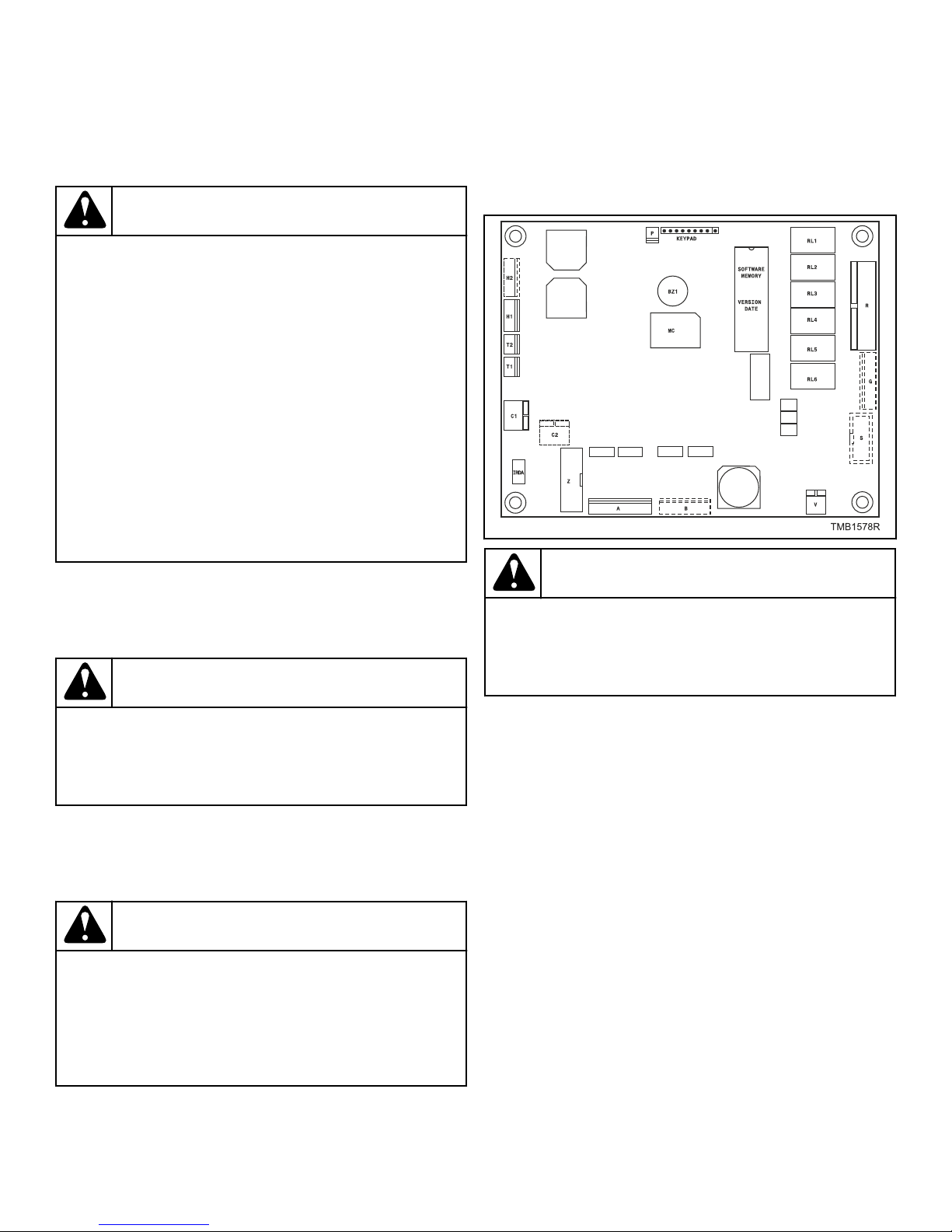
Service information
Service information
General
WARNING
PROFESSIONAL REPAIRS IN ELECTRO INSTALLATION CAN BE CARRIED OUT ONLY BY SERVICE ORGANIZATION WITH PERMISSION GIVEN BY PRODUCER / SUPPLIER.
IN CASE OF ANY MAINTENANCE OR REPAIR DISCONNECT THE MACHINE FROM SOURCE OF ENERGY AND WAIT UNTIL THE MACHINE COOLS DOWN.
PLEASE FOLLOW ALL INSTRUCTIONS IN THE MANUALS AND THE LABELS AS WELL AS VALID BASIC
SECURITY LAWS IN ORDER TO PREVENT BURNS
AND SCALDS AND INJURIES CAUSED BY ELECTRICITY, HEATING POWER SUPPLY, MECHANICAL
MOVING PARTS.
Maintenance
VVV = Version
Programmer Circuit Board
C145
WARNING
Remove dirt from the keyboard by a damp cloth after disconnection from the power supply.
WARNING
Do not use aggresive soaps, caustic chemicals, gasoline or other petrochemical substances which can
damage the keyboard.
Follow the instructions from the installation-maintenance manual.
Information for Service
WARNING
Every circuit board has a sticker placed on the
eprom, which specifies the version and the date of
the software. This data along with the machine serial
no., order code must be given in all correspondence
or inquiries to the manufacturer.
XXX-VVV
XXX = (Software for the FLEX CONTROL dryer computer)
Connection to the wrong voltage supply may cause
serious bodily injury as well as damage to the electronic parts and to the wasching machine itself.
• Voltage : 200-240 Vac, 50/60 Hz
• Power : max 16 VA
• Memory :
C082
• EPROM (contains the software)
• EEPROM (contains the customized programs)
• Outputs : 6 relays
• Serial interface : RS485 (2 wire) networking between dryer
computer and external device (PC Computer)
• Display : LCD display
Instructions for Replacing the
Electronic Board and Keypad
• Switch off the main power supply.
• Open the front plate of the dryer.
• Turn the control board assembly holder to the front.
• Remove the connectors from the control board.
C085
• Remove the combination keyboard - electronic timer by the
rear side of the fascia panel.
• Put the new combination keyboard – electronic timer into the
machine and tighten the screws.
C083
©
Copyright, Alliance Laundry Systems LLC -
DO NOT COPY or TRANSMIT
54 Part No. D1621ENR3
Page 55
Service information
• Reconnect all the connectors.
• Turn the control board assembly holder back to its original
position.
• Close the front plate of the dryer.
• Now you can Switch On the power supply.
• The display should illuminate.
WARNING
MAKE SURE THAT YOU DON’T DAMAGE THE FLEX
CABLE OF THE KEYPAD WHEN YOU PUT THE CONTROL DRYER COMPUTER BACK INTO THE MACHINE.
C147
Instructions for Installing New Software
• Switch off the main power.
• Open the front plate of the dryer.
• Turn the control board assembly holder to the front until you
have access to the control board.
• The EPROM with the implemented software is the only IC on
the logic board that can be removed.
• Take the EPROM out of the IC-holder (by a dedicated tool)
and replace it by a new one.
• Make sure that you put the new chip at the right position. See
picture.
• Turn the control board assembly holder back to its original
position.
• Close the cover plate of the dryer.
• Switch on the main power.
• The display should illuminate.
• If the software is compatible with the previous software: the
new software can be used without reinitialization.
• You have to clear all the error messages in the Service-menu,
if you want to make a correct inspection of the functioning of
the new installed software.
• If the software is not 100% compatible with the previous software version:
• The new software will generate a diagnostic message 35.
When fault message 35 occurs, you have to reset the settings of the configuration and initialization menu.
• This can be easily done by Selecting Reset Factory Set-
tings in the Configuration Menu.
• » This is explained in Chapter: Basic Description of
Controls.
• All the Custom Settings will be lost.
• Go through the Menu items of the Configuration and Initialization Menu one by one to ensure that all the settings
do correspond with the ones you prefer.
• Switch the power Off/On.
• Now the FLEX CONTROL Dryer computer is ready to start a
new cycle.
©
Copyright, Alliance Laundry Systems LLC -
DO NOT COPY or TRANSMIT
55 Part No. D1621ENR3
Page 56
Specification of Your Machine
Data
MACHINE DATA
Type : Phases :
Serial Number : Frequency :
Voltage : Output :
Heating : O Heat Pump
ELECTRONIC DATA
Programmer Type :
Serial Number :
Software Version :
Software Date :
Keyboard :
Specification of Your Machine
MACHINE CONFIGURATION DATA
FUNCTION DATA ENTERED
Machine Type :
Brightness Display :
Heating Type : O Heat Pump
Reversing System O Yes O No
Humidity Control System
Temperature O Celsius O Fahrenheit
Warning Filter : Cycles
O Yes O No
©
Copyright, Alliance Laundry Systems LLC -
DO NOT COPY or TRANSMIT
56 Part No. D1621ENR3
Page 57
Specification of Your Machine
MACHINE INITIALIZATION DATA
FUNCTION DATA ENTERED
Language :
Enabled Programs : O 1 O 2 O 3 O 4 O 5 O 6 O 7 O 8 O 9 O 10 O 11 O 12 O 13 O 14 O 15 O 16 O 17 O 18 O 19 O 20
Set Unwrinkle Time : Minutes
Unwrinkle On Time : Seconds
Unwrinkle Off Time : Minutes
Service Interval :
Buzzer Time : Seconds
Allow Advance O Yes O No
Manual Override O Yes O No
Default Motor Turn
Time
Default Motor Rest
Time
: Seconds
: Seconds
©
Copyright, Alliance Laundry Systems LLC -
DO NOT COPY or TRANSMIT
57 Part No. D1621ENR3
 Loading...