

Page 1
Washer-Extractors
Cabinet Hardmount – OPL
V-Series Microcomputer
2 Speed and Variable-Speed
Refer to Page 3 for Model Identification
Programming
Keep These Instructions for Future Reference.
(If this machine changes ownership, this manual must accompany machine.)
www.comlaundry.com
CHM166C
Part No. F232141R3
December 2008
Page 2

Page 3

Table of
Contents
Introduction......................................................................................... 2
Model Identification ............................................................................. 2
Nameplate Location.............................................................................. 3
Replacement Parts ................................................................................ 3
Customer Service.................................................................................. 3
Safety Information.............................................................................. 4
Important Safety Instructions ............................................................... 4
Safety Decals ........................................................................................ 6
Operator Safety..................................................................................... 7
Programming ...................................................................................... 8
Entering Program Mode ....................................................................... 8
Cycle Charts.......................................................................................... 13
© Copyright 2008, Alliance Laundry Systems LLC
All rights reserved. No part of the contents of this book may be reproduced or transmitted in any form or by any
means without the expressed written consent of the publisher.
F232141
© Copyright, Alliance Laundry Systems LLC – DO NOT COPY or TRANSMIT
1
Page 4

Introduction
Model Identification
Information in this manual is applicable to these
models:
HC80VNV SC40VN2 UC125VNV UC40VNV
SC125VNV SC40VNV UC18VN2 UC50VN2
SC18VN2 SC50VN2 UC20VN2 UC50VNV
SC20VN2 SC50VNV UC27VN2 UC60VN2
SC27VN2 SC60VN2 UC30VN2 UC60VNF
SC30VN2 SC60VNF UC35VN2 UC60VNV
SC35VN2 SC60VNV UC35VNV UC80VNV
SC35VNV SC80VNV UC40VN2
2
© Copyright, Alliance Laundry Systems LLC – DO NOT COPY or TRANSMIT
F232141
Page 5
Introduction
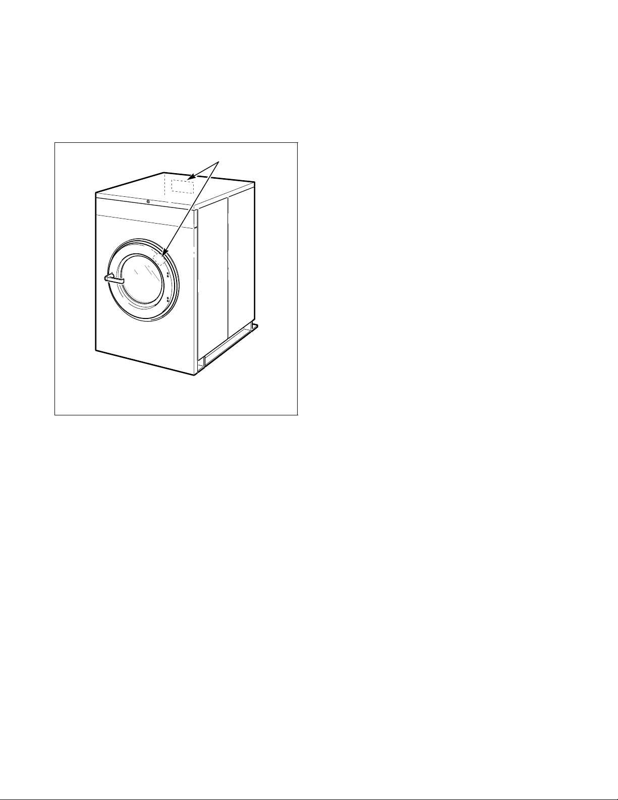
Nameplate Location
The nameplate is located at the rear of the machine and
inside door. Always provide the machine’s serial
number and model number when ordering parts or
when seeking technical assistance.
1
Replacement Parts
If literature or replacement parts are required, contact
the source from which the machine was purchased or
contact Alliance Laundry Systems LLC at
(920) 748-3950 for the name and address of the
nearest authorized parts distributor.
Customer Service
For technical assistance, call the following number:
(920) 748-3121
Ripon, Wisconsin
www.comlaundry.com
1 Nameplate
CHM167R
F232141
© Copyright, Alliance Laundry Systems LLC – DO NOT COPY or TRANSMIT
3
Page 6

Safety Information
Precautionary statements (“DANGER,” “WARNING”
and “CAUTION”), followed by specific instructions,
are found in this manual and on machine decals. These
precautions are intended for the personal safety of the
operator, user, servicer and those maintaining the
machine.
DANGER
DANGER indicates the presence of a
hazard that will cause severe personal
injury, death, or substantial property
damage if the danger is ignored.
WARNING
WARNING indicates the presence of a
hazard that can cause severe personal
injury, death, or substantial property
damage if the warning is ignored.
CAUTION
CAUTION indicates the presence of a
hazard that will or can cause minor
personal injury or property damage if the
caution is ignored.
Additional precautionary statements (“IMPORTANT”
and “NOTE”) are followed by specific instructions.
IMPORTANT: The word “IMPORTANT” is used
to inform the reader of specific procedures where
minor machine damage will occur if the procedure
is not followed.
NOTE: The word “NOTE” is used to communicate
installation, operation, maintenance or servicing
information that is important but not hazard
related.
Important Safety Instructions
WARNING
To reduce the risk of fire, electric shock,
serious injury or death to persons when
using your washer, follow these basic
precautions:
W023
1. Read all instructions before using the washer.
2. Refer to the GROUNDING INSTRUCTIONS in
the INSTALLATION MANUAL for the proper
grounding of the washer.
3. Do not wash textiles that have been previously
cleaned in, washed in, soaked in, or spotted with
gasoline, dry-cleaning solvents, or other
flammable or explosive substances as they give
off vapors that could ignite or explode.
4. Do not add gasoline, dry-cleaning solvents, or
other flammable or explosive substances to the
wash water. These substances give off vapors that
could ignite or explode.
5. Under certain conditions, hydrogen gas may be
produced in a hot water system that has not been
used for two weeks or more. HYDROGEN GAS
IS EXPLOSIVE. If the hot water system has not
been used for such a period, before using a
washing machine or combination washer-dryer,
turn on all hot water faucets and let the water
flow from each for several minutes. This will
release any accumulated hydrogen gas. The gas is
flammable; do not smoke or use an open flame
during this time.
6. Do not allow children to play on or in the washer.
Close supervision of children is necessary when
the washer is used near children. This is a safety
rule for all appliances.
7. Before the washer is removed from service or
discarded, remove the door to the washing
compartment.
8. Do not reach into the washer if the wash drum is
moving.
4
© Copyright, Alliance Laundry Systems LLC – DO NOT COPY or TRANSMIT
F232141
Page 7

Safety Information
9. Do not install or store the washer where it will be
exposed to water and/or weather.
10. Do not tamper with the controls.
11. Do not repair or replace any part of the washer, or
attempt any servicing unless specifically
recommended in the user-maintenance
instructions or in published user-repair
instructions that the user understands and has the
skills to carry out.
12. To reduce the risk of an electric shock or fire, DO
NOT use an extension cord or an adapter to
connect the washer to the electrical power source.
13. Use washer only for its intended purpose,
washing textiles.
14. Never wash machine parts or automotive parts in
the machine. This could result in serious damage
to the basket.
15. ALWAYS disconnect the washer from electrical
supply before attempting any service. Disconnect
the power cord by grasping the plug, not the cord.
16. Install the washer according to the
INSTALLATION INSTRUCTIONS. All
connections for water, drain, electrical power and
grounding must comply with local codes and be
made by licensed personnel when required.
17. To reduce the risk of fire, textiles which have
traces of any flammable substances such as
vegetable oil, cooking oil, machine oil,
flammable chemicals, thinner, etc. or anything
containing wax or chemicals such as in mops and
cleaning cloths, must not be put into the washer.
These flammable substances may cause the
fabric to catch on fire by itself.
18. Do not use fabric softeners or products to
eliminate static unless recommended by the
manufacturer of the fabric softener or product.
19. Keep washer in good condition. Bumping or
dropping the washer can damage safety features.
If this occurs, have washer checked by a qualified
service person.
20. If the supply cord is damaged, it must be replaced
by a special cord or assembly available from the
manufacturer or its service agent.
21. Be sure water connections have a shut-off valve
and that fill hose connections are tight. CLOSE
the shut-off valves at the end of each wash day.
22. Loading door MUST BE CLOSED any time the
washer is to fill, tumble or spin. DO NOT bypass
the loading door switch by permitting the washer
to operate with the loading door open.
23. Always read and follow manufacturer’s
instructions on packages of laundry and cleaning
aids. Heed all warnings or precautions. To reduce
the risk of poisoning or chemical burns, keep
them out of the reach of children at all times
(preferably in a locked cabinet).
24. Always follow the fabric care instructions
supplied by the textile manufacturer.
25. Never operate the washer with any guards and/or
panels removed.
26. DO NOT operate the washer with missing or
broken parts.
27. DO NOT bypass any safety devices.
28. Failure to install, maintain and/or operate this
washer according to the manufacturer’s
instructions may result in conditions which can
produce bodily injury and/or property damage.
NOTE: The WARNINGS and IMPORTANT
SAFETY INSTRUCTIONS appearing in this
manual are not meant to cover all possible
conditions and situations that may occur. Common
sense, caution and care must be exercised when
installing, maintaining or operating the washer.
Any problems or conditions not understood should be
reported to the dealer, distributor, service agent or the
manufacturer.
F232141
© Copyright, Alliance Laundry Systems LLC – DO NOT COPY or TRANSMIT
5
Page 8

Safety Information
WARNING
This machine must be installed, adjusted,
and serviced by qualified electrical
maintenance personnel familiar with the
construction and operation of this type of
machinery. They must also be familiar
with the potential hazards involved.
Failure to observe this warning may result
in personal injury and/or equipment
damage, and may void the warranty.
SW004
IMPORTANT: Ensure that the recommended
clearances for inspection and maintenance
are provided. Never allow the inspection and
maintenance space to be blocked.
WARNING
Install the machine on a level floor of
sufficient strength. Failure to do so may
result in conditions which can produce
serious injury, death and/or property
damage.
W703
CAUTION
Be careful around the open door,
particularly when loading from a level
below the door. Impact with door edges
can cause personal injury.
SW025
WARNING
Never touch internal or external steam
pipes, connections, or components.
These surfaces can be extremely hot and
will cause severe burns. The steam must
be turned off and the pipe, connections,
and components allowed to cool before
the pipe can be touched.
SW014
Safety Decals
Safety decals appear at crucial locations on the
machine. Failure to maintain legible safety decals
could result in injury to the operator or service
technician.
To provide personal safety and keep the machine in
proper working order, follow all maintenance and
safety procedures presented in this manual. If
questions regarding safety arise, contact the
manufacturer immediately.
Use manufacturer-authorized spare parts to avoid
safety hazards.
6
© Copyright, Alliance Laundry Systems LLC – DO NOT COPY or TRANSMIT
F232141
Page 9

Safety Information
Operator Safety
WARNING
NEVER insert hands or objects into
basket until it has completely stopped.
Doing so could result in serious injury.
SW012
To ensure the safety of machine operators, the
following maintenance checks must be performed
daily:
1. Prior to operating the machine, verify that all
warning signs are present and legible. Missing or
illegible signs must be replaced immediately.
Make certain that spares are available.
2. Check door interlock before starting operation of
the machine:
a. Attempt to start the machine with the door
open. The machine should not start with the
door open.
b. Close the door without locking it and attempt
to start the machine. The machine should not
start with the door unlocked.
Do not bypass any safety devices in the machine.
WARNING
Never operate the machine with a
bypassed or disconnected balance
system. Operating the machine with
severe out-of-balance loads could result
in personal injury and serious equipment
damage.
SW039
c. Close and lock the door and start a cycle.
Attempt to open the door while the cycle is in
progress. The door should not open.
If the door lock and interlock are not functioning
properly, call a service technician.
3. Do not attempt to operate the machine if any of
the following conditions are present:
a. The door does not remain securely locked
during the entire cycle.
b. Excessively high water level is evident.
c. Machine is not connected to a properly
grounded circuit.
F232141
© Copyright, Alliance Laundry Systems LLC – DO NOT COPY or TRANSMIT
7
Page 10

Programming
Entering Program Mode
1. Unlock and raise top cover.
2. Remove control module cover.
3. Locate the Run/Program Mode switch near
center of computer board inside control module.
Refer to Figure 1.
2
1 Run/Program Mode Switch
2 Computer Board
Figure 1
1
CHM282R
Procedures for Calibration of T emperature
Probe for V-Computer Controlled
Machines
1. Disconnect power to the machine. Ensure that the
V-Computer has no input power applied.
2. Mount an accurate temperature sensor probe
(part of temperature calibration equipment) in the
bottom of the machine basket. Make sure the
wires for the probe exit the top of the door to
ensure that the door gasket does not leak.
3. Close door and ensure that the door is locked.
4. Open machine top cover and remove control
component cover(s), if necessary, to gain access
to the V-Computer and output control board.
WARNING
Dangerous voltages are present in the
electrical control box(es) and at the motor
terminals. Only qualified personnel familiar
with electrical test procedures, test
equipment, and safety precautions should
attempt adjustments and troubleshooting.
Disconnect power from the mac hine before
removing the control bo x cover , and bef ore
attempting any service procedures.
SW005
4. Flip switch to down position to enter PROGRAM
Mode. Display will show temperature of sump.
8
© Copyright, Alliance Laundry Systems LLC – DO NOT COPY or TRANSMIT
F232141
Page 11

5. On Variable-Speed machines, note wire
connections on the output control board for
the AC Drive control. Some machines will
have six wires connected to “STF,” “STR,”
“RH,” “RM,” “RL” and “COM” individually or a
single connector labeled “J11-1.” Remove
these wires or connector to ensure the
basket will not rotate. Also remove the input
power to the drive.
NOTE: If this step is not followed, damage can
occur to the calibration temperature probe.
6. On Fixed-speed machines, remove fuses from
the “FWD,” “REV” and “SPIN” outputs to
ensure the basket will not rotate.
WARNING
NEVER insert hands or objects into basket
until it has completely stopped. Doing so
could result in serious injury.
Programming
SW012
7. Restore input power to the machine.
8. Wait until machine message displays “CY”
followed by a two-digit cycle number (01 – 30).
9. Program one of the unused cycles to Fill to High
Level using both of the water inlet valves. Select
a time limit for the step that would be sufficient
to complete the calibration procedure.
10. When machine has completed the Fill to High
Level, press and hold the Up (arrow) key on the
keypad to display the machine temperature.
Make sure that the V-Computer is in the correct
temperature unit (deg F or C). Refer to
Programming Setup Options section of manual
to change.
11. Using a flat-bladed screwdriver, turn the machine
temperature calibration screw until the displayed
temperature of the machine and the temperature
of the temperature calibration equipment are
accurate to the nearest degree (refer to Figure 2).
CHM521R
CHM521R
Figure 2
12. When the temperatures match, calibration is
completed.
13. Remove power from the machine input.
14. Reconnect any wires/connectors/fuses that were
removed, making sure they are installed exactly
as they were removed.
15. Reinstall all machine protective covers.
16. Remove the temperature calibration probe from
the bottom of the machine basket.
17. Restore input power to machine.
F232141
18. Machine is now ready for use.
© Copyright, Alliance Laundry Systems LLC – DO NOT COPY or TRANSMIT
9
Page 12

Programming
Programming Setup Options
1. With display showing sump temperature, press
Stop (*) key to enter SETUP Mode.
2. Use Up or Down (arrow) key to scroll through
setup options. Refer to Tab l e 1 for possible setup
options and description.
Setup Options Description
“
FAr”/“CEL” Select “FA r ”: degrees are displayed
in Fahrenheit.
Select “
displayed in Celsius.
“
noHt”/“HEAT” Select “noHt”: no heat is available
during a cycle regardless of
programmed temperature setting.
Select “HEAT”: heat is available as
long as a temperature is
programmed.
“
SUP5”/“AFIL” Select “SUP5”: a fifth or sixth
supply can be programmed in a
cycle step.
Select “
be programmed to low, medium or
high water level in a cycle step.
“
tFIL”/“ntFL” Select “tFIL”: a temperature-
controlled fill can be programmed
for any segment. Select “ntFL”:
feature is disabled.
“
COOL”/“noCL” Select “COOL”: automatic cool-
down feature is enabled allowing
cold water to flush into wash before
a drain if temperature is 140ºF or
above.
Select “
CEL”: degrees are
AFIL”: auxiliary fills can
noCL”: feature is disabled.
Table 1
Programming a Cycle
1. With the display showing sump temperature,
press the Up (arrow) key to edit a cycle. The
display will show “CY01”.
NOTE: On VNV and VN2 models, 26 of the
30 cycles available are pre-programmed.
2. Press Up or Down (arrow) key until cycle to be
edited is displayed. The display will show
“CY01”. Press Start (#) key to begin editing
selected cycle.
3. Use Up or Down (arrow) key to select agitation
action. Refer to Ta ble 2 for agitation action
options. Press Start (#) key.
NOTE: This action applies to entire cycle.
Agitation Action Options
Display Description Percentage
AG 1 27 seconds forward,
3 seconds pause,
27 seconds reverse,
3 seconds pause
AG 2 10 seconds forward,
20 seconds pause,
10 seconds reverse,
20 seconds pause
AG 3 3 seconds forward,
27 seconds pause,
3 seconds reverse,
27 seconds pause
AG 4 4 seconds forward,
56 seconds pause,
4 seconds reverse,
56 seconds pause
90%
33%
10%
6.7%
WARNING
To prevent personal injury, avoid contact
with inlet water temperatures higher than
125° Fahrenheit (51° Celsius) and hot
surfaces.
3. Press the Start (#) key to accept the option and to
then scroll forward to the next setup option.
4. Press the Stop (*) key anytime to exit SETUP
Mode. The display will show sump temperature.
10
© Copyright, Alliance Laundry Systems LLC – DO NOT COPY or TRANSMIT
W748
Table 2
4. On VNV models only, use Up or Down (arrow)
key to select agitation speed: normal (“AGSn”)
or gentle (“AGSL”). Press Start (#) key.
5. Use Up or Down (arrow) key to select next
option: “PUnP” or “nPnP”. This is for a future
recirculation feature. It has no effect on wash
cycle. Select “nPnP” and press Start (#) key.
F232141
Page 13

Programming
Programming Cycle Segments
NOTE: Each cycle program can be customized
within the 11 program segments contained in a
cycle. A time must be entered for each segment. To
skip a segment or spin, set the time to “00” and
press Start (#) key. Refer to Ta b le 3 for time
parameters.
Time Parameters
Segment Minimum Maximum
PreWash “
Wash “
Fill 1 – Fill 9
“
FIL1”... “FIL9”
Intermediate Spin 30 seconds 240 seconds
Final Spin 1 minute 10 minutes
NOTE: Spin times in cycle segments 1 – 10 are
entered in seconds (30 to 240), and time for final
spin in segment 11 is entered in minutes (1 to 10).
6. Press Up (arrow) key until display shows
7. Use Up or Down (arrow) key to select Segment
PrE” 2 minutes 30 minutes
UASH” 2 minutes 20 minutes
2 minutes 15 minutes
Table 3
segment to be edited. Press Start (#) key.
Time. Set this value to “00” to skip segment.
Press Start (#) key.
11. Use Up or Down (arrow) key to select Supply
Option. Refer to Tab l e 4.
Supply Options
Display Supply
SUP0 No Supply
SUP1 Supply 1
SUP2 Supply 2
SUP3 Supply 3
SUP4 Supply 4
SUP5 Supply 5*
SUP6 Supply 1 and 5*
SUP7 Supply 3 and 4
*This is available only if the “
option is set to “
SUP5”.
SUP5”/“AFIL” setup
Table 4
12. Press Start (#) key.
13. Use Up or Down (arrow) key to select Segment
Temperature: 75° to 200°F or 25° to 93°C
. Set
this value to zero to disable auxiliary heat and
temperature-controlled fill. Press Start (#) key.
NOTE: Only available if Temperature-Controlled
Fill or Auxiliary Heat Setup Option is enabled.
8. If Temperature-Controlled Fill Setup Option is
enabled, display will show “tFIL”. Press
Start (#) key.
9. Use Up or Down (arrow) key to select Fill
Temperature: Cold (“CFIL”), Hot (“HFIL”),
Warm (“bFIL”) or Auxiliary (“AFIL”). Press
Start (#) key.
NOTE: An auxiliary fill is available only if
“SUP5”/“AFIL” setup option is set to “AFIL”.
10. Use Up or Down (arrow) key to select Fill Level:
Low (“Lo”), Medium (“nEd”) or High (“HI”).
Press Start (#) key.
WARNING
To prevent personal injury, avoid contact
with inlet water temperatures higher than
125° Fahrenheit (51° Celsius) and hot
surfaces.
W748
F232141
© Copyright, Alliance Laundry Systems LLC – DO NOT COPY or TRANSMIT
11
Page 14

Programming
14. Use Up or Down (arrow) key to select Drain
Option: “drAI” (drain) or “nodr” (no drain).
NOTE: The drain step in the final segment cannot
be skipped.
15. For VNV models only, select spin speed for
Fill 9: “SPn1” (Low), “SPn2” (Medium), or
“SPn3” (High).
16. Display will flash “SPIn” and “tInE”. Use Up or
Down (arrow) key to select spin time: 1 to
10 minutes (00 for no spin). Press Start (#) key.
The display will show the identifier for the next
program segment.
17. Press the Stop (*) key to complete the cycle
programming procedure.
Test Cycle
To select test cycle:
1. Flip program switch to up position (RUN Mode).
2. Press Down (arrow) key. Display will show
“tESt” and “CYC”.
3. Press Start (#) key to begin.
The ability to advance to the next cycle step is possible
by pressing the Start (#) key.
Refer to the following Cycle Charts section for
detailed description of cycles.
12
© Copyright, Alliance Laundry Systems LLC – DO NOT COPY or TRANSMIT
F232141
Page 15

Programming
Cycle Charts
V-Computer Standard OPL Cycles
Cycle
Program
Agitation AG 1AG 1AG 1AG 1AG 1AG 1AG 1AG 1
Wash Speed AGSn AGSn AGSn AGSn AGSn AGSn AGSn AGSn
Pump nPnP nPnP nPnP nPnP nPnP nPnP nPnP nPnP
PreWash
Time (Min.)00222222
Water Both (warm) Both (warm) Both (warm) Both (warm) Both (warm) Both (warm)
Level High High High Low High High
Supply 000000
Temp (F) 000000
Drain DrAI DrAI DrAI DrAI DrAI DrAI
Spin (Sec.) 000000
Wash
Time (Min.)77776699
Water Hot Hot Hot Hot Hot Hot Hot Hot
Level Low Low Low Low Low Low Low Low
Supply11111111
Temp (F)00000000
Drain DrAI DrAI DrAI DrAI DrAI DrAI DrAI DrAI
Spin (Sec.)00000000
Fill 1
Time (Min.)44777747
Water Hot Hot Hot Hot Hot Hot Hot Hot
Level High High Low Low Low Low High High
Supply00221102
Temp (F)00000000
Drain DrAI DrAI DrAI DrAI DrAI DrAI DrAI DrAI
Spin (Sec.)00000000
Fill 2
Time (Min.)22447724
Water Both (warm) Both (warm) Hot Hot Hot Hot Both (warm) Hot
Level High High High High Low Low High High
Supply00002200
Temp (F)00000000
Drain DrAI DrAI DrAI DrAI DrAI DrAI DrAI DrAI
Spin (Sec.)30600000300
Fill 3
Time (Min.)40224442
Water Both (warm) Both (warm) Both (warm) Hot Hot Both (warm) Both (warm)
Level Low High High High High Low Low
Supply3 000030
Temp (F)0 000000
Drain DrAI DrAI DrAI DrAI DrAI DrAI DrAI
Spin (Sec.)240 30060024030
Permanent
Press
Light Soil
1
2
Cotton
Terrycloth
Light Soil
3
Permanent
Press
Medium Soil
4
Cotton
Terrycloth
Medium Soil
5
Permanent
Press
Heavy Soil
6
Cotton
Te rr y c lo t h
Heavy Soil
7
Table Napery
Blends
Colors
8
Table Napery
Blends
Whites
F232141
© Copyright, Alliance Laundry Systems LLC – DO NOT COPY or TRANSMIT
13
Page 16

Programming
V-Computer Standard OPL Cycles (Continued)
Cycle
Program
Fill 4
Time (Min.)00402204
Water Both (warm) Both (warm) Both (warm) Both (warm)
Level Low High High Low
Supply 3003
Tem p (F) 0 0 0 0
Drain DrAI DrAI DrAI DrAI
Spin (Sec.) 240 30 30 240
Fill 5
Time (Min.)00004000
Wat er Bo t h ( warm )
Level Low
Supply 3
Tem p (F) 0
Drain DrAI
Spin (Sec.) 240
Fill 6
Time (Min.)00000000
Wat er
Level
Supply
Tem p (F)
Drain
Spin (Sec.)
Fill 7
Time (Min.)00000000
Wat er
Level
Supply
Tem p (F)
Drain
Spin (Sec.)
Fill 8
Time (Min.)00000000
Wat er
Level
Supply
Tem p (F)
Drain
Spin (Sec.)
Fill 9
Time (Min.)04040400
Water Both (warm) Both (warm) Both (warm)
Level Low Low Low
Supply333
Temp (F)000
Drain DrAI DrAI DrAI
Spin SPn3 SPn3 SPn3
Spin (Min.) 5
Permanent
Press
Light Soil
1
2
Cotton
Terrycloth
Light Soil
3
Permanent
Press
Medium Soil
4
Cotton
Terrycloth
Medium Soil
5
Permanent
Press
Heavy Soil
6
Cotton
Te rr y c lo t h
Heavy Soil
7
Table Napery
Blends
Colors
8
Table Napery
Blends
Whites
14
© Copyright, Alliance Laundry Systems LLC – DO NOT COPY or TRANSMIT
F232141
Page 17

Programming
V-Computer Standard OPL Cycles (Continued)
Cycle
Program
Agitation AG 1AG 1AG 1AG 1AG 1AG 1AG 1AG 1
Wash Speed AGSn AGSn AGSn AGSn AGSn AGSn AGSn AGSn
Pump nPnP nPnP nPnP nPnP nPnP nPnP nPnP nPnP
PreWash
Time (Min.)22222200
Water Both (warm) Both (warm) Both (warm) Hot Both (warm) Both (warm)
Level High High High High High High
Supply001110
Temp (F)000000
Drain DrAI DrAI DrAI DrAI DrAI DrAI
Spin (Sec.)000000
Wash
Time (Min.)10101067757
Water Hot Hot Hot Hot Hot Hot Cold Both (warm)
Level Low Low Low Low Low Low High High
Supply11112111
Temp (F)00000000
Drain DrAI DrAI DrAI DrAI DrAI DrAI DrAI DrAI
Spin (Sec.)00000000
Fill 1
Time (Min.)666122244
Water Hot Hot Hot Hot Both (warm) Both (warm) Cold Both (warm)
Level Low Low Low Low High High High High
Supply12220000
Temp (F)00000000
Drain DrAI DrAI DrAI DrAI DrAI DrAI DrAI DrAI
Spin (Sec.)00000000
Fill 2
Time (Min.)44442222
Water Hot Hot Hot Hot Both (warm) Both (warm) Cold Hot
Level HighHighHighHighHighHighHighHigh
Supply00200000
Temp (F)00000000
Drain DrAI DrAI DrAI DrAI DrAI DrAI DrAI DrAI
Spin (Sec.)000030303030
Fill 3
Time (Min.)22224442
Water Both (warm) Both (warm) Both (warm) Both (warm) Both (warm) Both (warm) Cold Both (warm)
Level High High High High Low Low High High
Supply00003330
Temp (F)00000000
Drain DrAI DrAI DrAI DrAI DrAI DrAI DrAI DrAI
Spin (Sec.)0000240240240240
VISA
Table Napery
Colors
9
10
VISA
Table Napery
Whites
11
Rags
Heavy Soil
12
Reclaim13Personals with
Bleach
14
Personals
no Bleach
15
Delicate
Spreads
Cold Water
16
Delicate
Spreads
Warm Water
F232141
© Copyright, Alliance Laundry Systems LLC – DO NOT COPY or TRANSMIT
15
Page 18

Programming
V-Computer Standard OPL Cycles (Continued)
Cycle
Program
Fill 4
Time (Min.)22220000
Water Cold Cold Both (warm) Both (warm)
Level High High High High
Supply0000
Temp (F)0000
Drain DrAI DrAI DrAI DrAI
Spin (Sec.)30306030
Fill 5
Time (Min.)44440000
Water Cold Cold Both (warm) Both (warm)
Level Low Low High Low
Supply3303
Temp (F)0000
Drain DrAI DrAI DrAI DrAI
Spin (Sec.) 240 240 60 240
Fill 6
Time (Min.)00000000
Wat er
Level
Supply
Tem p (F)
Drain
Spin (Sec.)
Fill 7
Time (Min.)00000000
Wat er
Level
Supply
Tem p (F)
Drain
Spin (Sec.)
Fill 8
Time (Min.)00000000
Wat er
Level
Supply
Tem p (F)
Drain
Spin (Sec.)
Fill 9
Time (Min.)00400000
Wat er B o t h ( war m )
Level Low
Supply 3
Tem p (F) 0
Drain DrAI
Spin SPn3
Spin (Min.) 6
VISA
Table Napery
Colors
9
10
VISA
Table Napery
Whites
11
Rags
Heavy Soil
12
Reclaim13Personals with
Bleach
14
Personals
no Bleach
15
Delicate
Spreads
Cold Water
16
Delicate
Spreads
Warm Water
16
© Copyright, Alliance Laundry Systems LLC – DO NOT COPY or TRANSMIT
F232141
Page 19

Programming
V-Computer Standard OPL Cycles (Continued)
Cycle
Program
Agitation AG 1 AG 1 AG 1 AG 1 AG 1 AG 1 AG 1 AG 1 AG 1 AG 2
Was h S p eed AGSn AGSn AGSn AGSn AGSn AGSn AGSn AGSn AGSn AGSn
Pump nPnP nPnP nPnP nPnP nPnP nPnP nPnP nPnP nPnP nPnP
PreWash
Time (Min.) 8 0 8 0 6 8 0 8 0 6
Water Cold Cold Cold Cold Cold Cold
Level High High High High High High
Supply 1 1 1 1 1 1
Temp (C) 40º 40º 40º 40º 40º 40º
Drain DrAI DrAI DrAI DrAI DrAI DrAI
Spin (Sec.) 0 0 0 0 0 0
Wash
Time (Min.) 10 10 10 10 8 10 10 10 10 8
Water Hot Hot Hot Hot Both (warm) Hot Hot Hot Hot Both (warm)
Level Low Low Low Low Low Low Low Low Low Low
Supply 2 2 2 2 2 2 2 2 2 2
Temp (C) 90º 90º 60º 60º 40º 90º 90º 60º 60º 40º
Drain DrAI DrAI DrAI DrAI DrAI DrAI DrAI DrAI DrAI DrAI
Spin (Sec.) 0 0 0 0 0 0 0 0 0 0
Fill 1
Time (Min.) 0 0 0 0 0 0 0 0 0 0
Wat er
Level
Supply
Tem p (C)
Drain
Spin (Sec.)
Fill 2
Time (Min.) 0 0 0 0 0 0 0 0 0 0
Wat er
Level
Supply
Tem p (C)
Drain
Spin (Sec.)
Fill 3
Time (Min.) 2 2 2 2 2 2 2 2 2 2
Water Cold Cold Cold Cold Cold Cold Cold Cold Cold Cold
Level Medium Medium Medium Medium Medium Medium Medium Medium Medium Medium
Supply 0 0 0 0 0 0 0 0 0 0
Temp (C)0 0000 0 0 0 0 0
Drain DrAI DrAI DrAI DrAI DrAI DrAI DrAI DrAI DrAI DrAI
Spin (Sec.)3030303030 30 30 30 30 30
Normal
90ºC
(PreWash)
21
22
Normal
90ºC
23
Normal
60ºC
(PreWash)
24
Normal
60ºC
25
Normal
40ºC
(PreWash)
26
Permanent
Press 90ºC
(PreWash)
27
Permanent
Press 90ºC
28
Permanent
Press 60ºC
(PreWash)
29
Permanent
Press 60ºC
30
Fine
40ºC
F232141
© Copyright, Alliance Laundry Systems LLC – DO NOT COPY or TRANSMIT
17
Page 20

Programming
V-Computer Standard OPL Cycles (Continued)
Cycle
Program
Fill 4
Time (Min.) 2 2 2 2 2 2 2 2 2 2
Water Cold Cold Cold Cold Cold Cold Cold Cold Cold Cold
Level Medium Medium Medium Medium Medium Medium Medium Medium Medium Medium
Supply 0 0 0 0 0 0 0 0 0 0
Temp (C)0 0000 0 0 0 0 0
Drain DrAI DrAI DrAI DrAI DrAI DrAI DrAI DrAI DrAI DrAI
Spin (Sec.)3030303030 30 30 30 30 30
Fill 5
Time (Min.) 2 2 2 2 2 2 2 2 2 2
Water Cold Cold Cold Cold Cold Cold Cold Cold Cold Cold
Level Medium Medium Medium Medium Medium Medium Medium Medium Medium Medium
Supply 0 0 0 0 0 0 0 0 0 0
Temp (C)0 0000 0 0 0 0 0
Drain DrAI DrAI DrAI DrAI DrAI DrAI DrAI DrAI DrAI DrAI
Spin (Sec.)3030303030 30 30 30 30 30
Fill 6
Time (Min.) 0 0 0 0 0 0 0 0 0 0
Wat er
Level
Supply
Tem p (C)
Drain
Spin (Sec.)
Fill 7
Time (Min.) 0 0 0 0 0 0 0 0 0 0
Wat er
Level
Supply
Tem p (C)
Drain
Spin (Sec.)
Fill 8
Time (Min.) 0 0 0 0 0 0 0 0 0 0
Wat er
Level
Supply
Tem p (C)
Drain
Spin (Sec.)
Fill 9
Time (Min.) 2 2 2 2 2 2 2 2 2 2
Water Cold Cold Cold Cold Cold Cold Cold Cold Cold Cold
Level Medium Medium Medium Medium Medium Medium Medium Medium Medium Medium
Supply 3 3 3 3 3 3 3 3 3 3
Temp (C)0 0000 0 0 0 0 0
Spin SPn3 SPn3 SPn3 SPn3 SPn3 SPn3 SPn3 SPn3 SPn3 SPn3
Spin (Min.) 6 6 6 6 6 2 2 2 2 2
Normal
90ºC
(PreWash)
21
22
Normal
90ºC
23
Normal
60ºC
(PreWash)
24
Normal
60ºC
25
Normal
40ºC
(PreWash)
26
Permanent
Press 90ºC
(PreWash)
27
Permanent
Press 90ºC
28
Permanent
Press 60ºC
(PreWash)
29
Permanent
Press 60ºC
30
Fine
40ºC
18
© Copyright, Alliance Laundry Systems LLC – DO NOT COPY or TRANSMIT
F232141
 Loading...