

Alliance Laundry Systems HC18SN2, UC40VN2, SC35VN2, UC20PN2, HC18VC2 Operation & Maintenance Manual
...Page 1
Washer-Extractors
Cabinet Hardmount
S, P, and V-Series Microcomputers Coin and
Non-Coin Models
Refer to Page 3 for Model Identification
NOTA: El manual en
español aparece después
del manual en inglés.
Operation/Maintenance
Keep These Instructions for Future Reference.
(If this machine changes ownership, this manual must accompany machine.)
www.comlaundry.com
CHM166C
Part No. F232137R2
April 2002
Page 2

Page 3

Table of
Contents
Introduction......................................................................................... 3
Model Identification ............................................................................. 3
Nameplate Location.............................................................................. 4
Replacement Parts ................................................................................ 4
Customer Service.................................................................................. 4
Safety Information.............................................................................. 5
Important Safety Instructions ............................................................... 5
Operation............................................................................................. 7
Control Panel ........................................................................................ 7
Display Indications............................................................................... 8
Operating Instructions .......................................................................... 12
Maintenance ........................................................................................ 15
Daily ..................................................................................................... 15
Beginning of Day............................................................................. 15
End of Day ....................................................................................... 15
Weekly.................................................................................................. 16
Monthly................................................................................................. 16
Quarterly............................................................................................... 19
Care of Stainless Steel.......................................................................... 20
© Copyright 2002, Alliance Laundry Systems LLC
All rights reserved. No part of the contents of this book may be reproduced or transmitted in any form or by any
means without the expressed written consent of the publisher.
F232137
© Copyright, Alliance Laundry Systems LLC – DO NOT COPY or TRANSMIT
1
Page 4

Notes
2
© Copyright, Alliance Laundry Systems LLC – DO NOT COPY or TRANSMIT
F232137
Page 5
Introduction
Model Identification
Information in this manual is applicable to these models:
HC18SN2 HC27VX2 HC50SN2 SC35VN2 UC20PN2 UC40VN2
HC18VC2 HC30SN2 HC50VC2 SC35VNV UC20VN2 UC40VNV
HC18VX2 HC30VC2 HC50VX2 SC40VN2 UC27PN2 UC50PN2
HC20SN2 HC30VX2 HC80VCV SC40VNV UC27VN2 UC50VN2
HC20VC2 HC35SN2 HC80VNV SC50VN2 UC30PN2 UC50VNV
HC20VX2 HC35VC2 HC80VXV SC50VNV UC30VN2 UC80VNV
HC25VC2 HC35VX2 SC18VN2 SC80VNV UC35PN2 UC125VNV
HC25VX2 HC40SN2 SC20VN2 SC125VNV UC35VN2
HC27SN2 HC40VC2 SC27VN2 UC18PN2 UC35VNV
HC27VC2 HC40VX2 SC30VN2 UC18VN2 UC40PN2
F232137
© Copyright, Alliance Laundry Systems LLC – DO NOT COPY or TRANSMIT
3
Page 6
Introduction
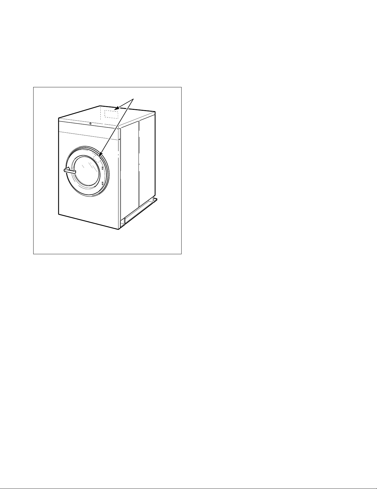
Nameplate Location
The nameplate is located at the rear of the machine and
inside door. Always provide the machine’s serial
number and model number when ordering parts or
when seeking technical assistance.
1
Replacement Parts
If literature or replacement parts are required, contact
the source from whom the machine was purchased or
contact Alliance Laundry Systems at (920) 748-3950
for the name and address of the nearest authorized
parts distributor.
Customer Service
For technical assistance, call any of the following
numbers:
(850) 718-1025
(850) 718-1026
Marianna, Florida U.S.A.
(920) 748-3121
Ripon, Wisconsin U.S.A.
1 Nameplate
CHM167R
Figure 1
4
© Copyright, Alliance Laundry Systems LLC – DO NOT COPY or TRANSMIT
F232137
Page 7
Safety Information
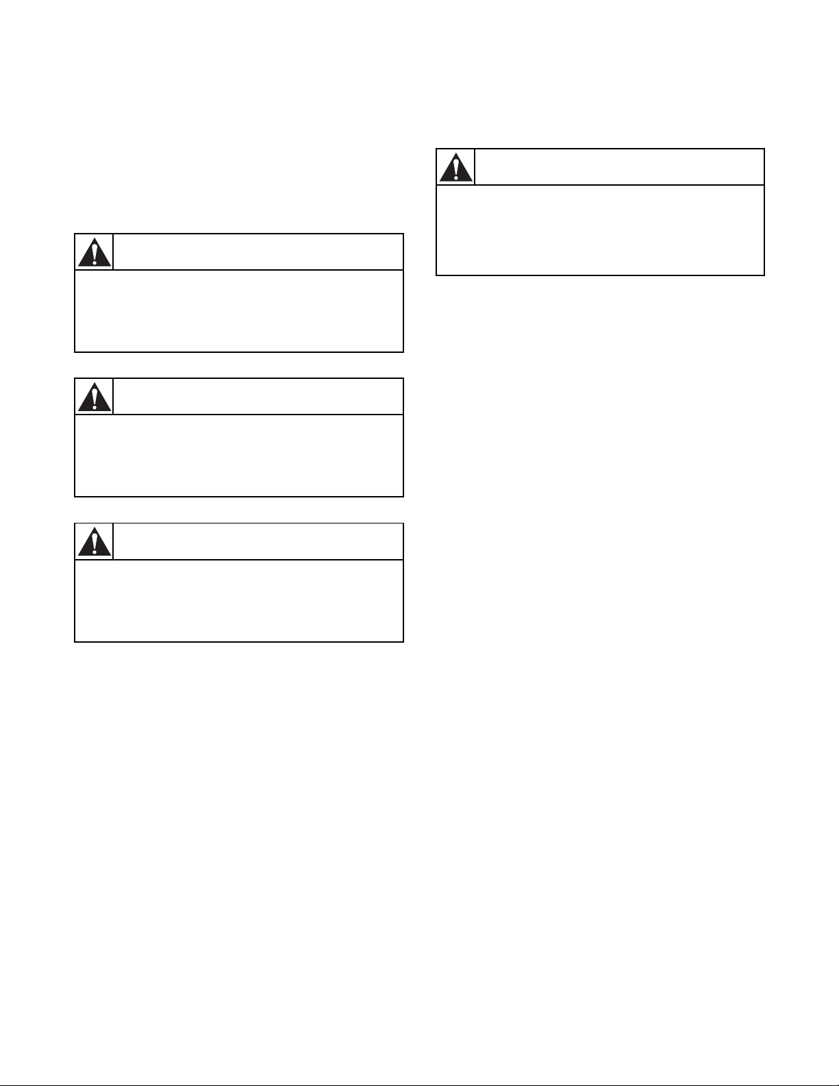
DANGER indicates the presence of a
hazard that will cause severe personal
injury, death, or substantial property
damage if the danger is ignored.
DANGER
WARNING indicates the presence of a
hazard that can cause severe personal
injury, death, or substantial property
damage if the warning is ignored.
WARNING
CAUTION indicates the presence of a
hazard that will or can cause minor
personal injury or property damage if the
caution is ignored.
CAUTION
Precautionary statements (“DANGER”, “WA R N I N G ”
and “CAUTION”), followed by specific instructions,
are found in this manual and on machine decals. These
precautions are intended for the personal safety of the
operator, user, servicer and those maintaining the
machine.
Important Safety Instructions
WARNING
To reduce the risk of fire, electric shock,
serious injury or death to persons when
using your washer, follow these basic
precautions:
W023E
1. Read all instructions before using the washer.
2. Refer to the Grounding Instructions in the
Installation Manual for the proper grounding of
the washer.
3. Do not wash textiles that have been previously
cleaned in, washed in, soaked in, or spotted with
gasoline, dry-cleaning solvents, or other
flammable or explosive substances as they give
off vapors that could ignite or explode.
4. Do not add gasoline, dry-cleaning solvents, or
other flammable or explosive substances to the
wash water. These substances give off vapors that
could ignite or explode.
Additional precautionary statements (“IMPORTANT”
and “NOTE”) are followed by specific instructions.
IMPORTANT: The word “IMPORTANT” is used
to inform the reader of specific procedures where
minor machine damage will occur if the procedure
is not followed.
NOTE: The word “NOTE” is used to communicate
installation, operation, maintenance or servicing
information that is important but not hazard
related.
5. Under certain conditions, hydrogen gas may be
produced in a hot water system that has not been
used for two weeks or more. HYDROGEN GAS
IS EXPLOSIVE. If the hot water system has not
been used for such a period, before using a
washing machine or combination washer-dryer,
turn on all hot water faucets and let the water
flow from each for several minutes. This will
release any accumulated hydrogen gas. The gas is
flammable; do not smoke or use an open flame
during this time.
6. Do not allow children to play on or in the washer.
Close supervision of children is necessary when
the washer is used near children. This is a safety
rule for all appliances.
7. Before the washer is removed from service or
discarded, remove the door to the washing
compartment.
8. Do not reach into the washer if the wash drum is
moving.
F232137
© Copyright, Alliance Laundry Systems LLC – DO NOT COPY or TRANSMIT
5
Page 8

Safety Information
9. Do not install or store the washer where it will be
exposed to water and/or weather.
10. Do not tamper with the controls.
11. Do not repair or replace any part of the washer, or
attempt any servicing unless specifically
recommended in the user-maintenance
instructions or in published user-repair
instructions that the user understands and has the
skills to carry out.
12. To reduce the risk of an electric shock or fire, DO
NOT use an extension cord or an adapter to
connect the washer to the electrical power source.
13. Use washer only for its intended purpose,
washing textiles.
14. ALWAYS disconnect the washer from electrical
supply before attempting any service. Disconnect
the power cord by grasping the plug, not the cord.
15. Install the washer according to the Installation
Instructions. All connections for water, drain,
electrical power and grounding must comply
with local codes and be made by licensed
personnel when required.
16. To reduce the risk of fire, textiles which have
traces of any flammable substances such as
vegetable oil, cooking oil, machine oil,
flammable chemicals, thinner, etc. or anything
containing wax or chemicals such as in mops and
cleaning cloths, must not be put into the washer.
These flammable substances may cause the
fabric to catch on fire by itself.
17. Do not use fabric softeners or products to
eliminate static unless recommended by the
manufacturer of the fabric softener or product.
18. Keep washer in good condition. Bumping or
dropping the washer can damage safety features.
If this occurs, have washer checked by a qualified
service person.
19. Replace worn power cords and/or loose plugs.
20. Be sure water connections have a shut-off valve
and that fill hose connections are tight. CLOSE
the shut-off valves at the end of each wash day.
21. Loading door MUST BE CLOSED any time the
washer is to fill, tumble or spin. DO NOT
bypass the loading door switch by permitting the
washer to operate with the loading door open.
22. Always read and follow manufacturer’s
instructions on packages of laundry and cleaning
aids. Heed all warnings or precautions. To reduce
the risk of poisoning or chemical burns, keep
them out of the reach of children at all times
(preferably in a locked cabinet).
23. Always follow the fabric care instructions
supplied by the textile manufacturer.
24. Never operate the washer with any guards
and/or panels removed.
25. DO NOT operate the washer with missing or
broken parts.
26. DO NOT bypass any safety devices.
27. Failure to install, maintain and/or operate this
washer according to the manufacturer’s
instructions may result in conditions which can
produce bodily injury and/or property damage.
NOTE: The WARNINGS and IMPORTANT
SAFETY INSTRUCTIONS appearing in this
manual are not meant to cover all possible
conditions and situations that may occur. Common
sense, caution and care must be exercised when
installing, maintaining or operating the washer.
Any problems or conditions not understood should be
reported to the dealer, distributor, service agent or the
manufacturer.
6
© Copyright, Alliance Laundry Systems LLC – DO NOT COPY or TRANSMIT
F232137
Page 9
Operation
Up Down Start Stop
1
2
3
4
5
6
8 7
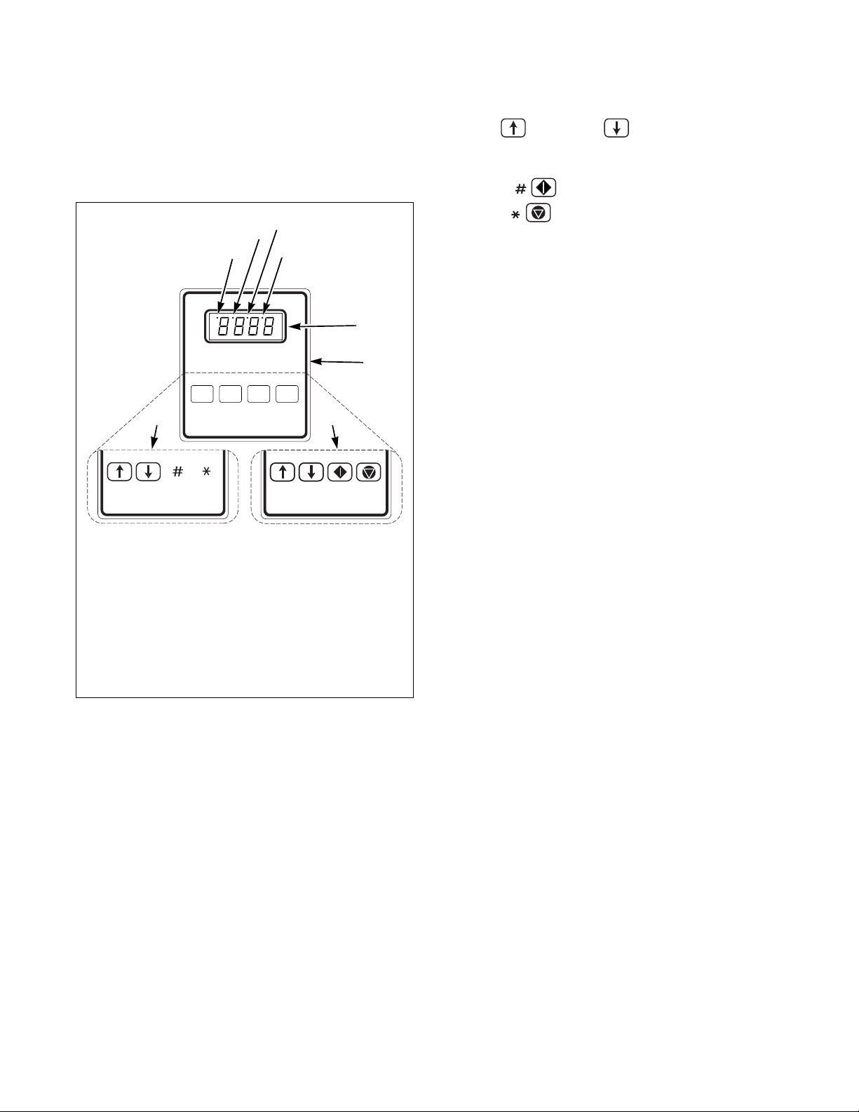
Control Panel
Figure 2 shows the control panel for S, P and
V-computer machines.
1 Out-of-Balance Condition for VCV, VXV
2 High Water Level
3 Medium Water Level for V-Series
4 Low Water Level
5 LED Display
6 Keys for Standard OPL
7 Keys for Icon OPL
8 Keys for VC2, VCV, VX2, VXV
The Up and Down keys are used in cycle
selection. Press these keys to move among cycles from
smaller to greater, or greater to smaller.
The Start key is used to start a cycle.
The Stop key is not active in normal Run
Mode. In Run Mode it is used only for stopping test
cycle.
The LED display informs operator of various
functions throughout operation of machine. Refer to
tables on the following pages for displays and their
meanings. Indicator lights in LED display indicate
out-of-balance conditions and water levels. Refer to
Figure 2.
B161R
Figure 2
F232137
© Copyright, Alliance Laundry Systems LLC – DO NOT COPY or TRANSMIT
7
Page 10
Operation
Display Indications
Table 1 through Ta b le 4 list the various displays and
what they mean. The operator should become familiar
with these computer displays.
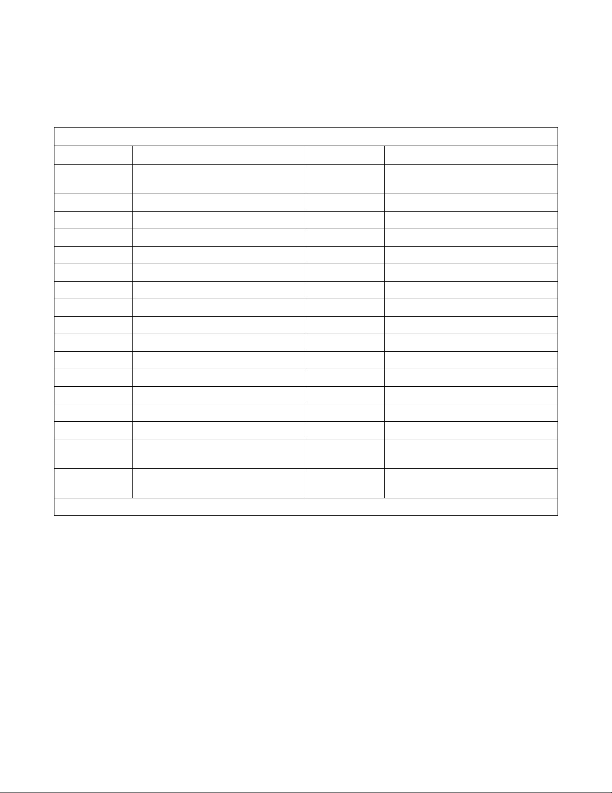
Display Indications for S-Series – Non-Coin
Display Meaning Display Meaning
S-05 Program identification code (ROM)
(this is an example only)
HoLd Wait...power has just been turned on HFIL Hot fill
CY Cycle (followed by two-digit number) LOLE Low water level
CHEC/CYC* Test cycle selected HILE High water level
FAr Degrees Fahrenheit SUP1 Supply 1
CEL Degrees Celsius SUP2 Supply 2
PrE Prewash segment (1st of 8 segments) SUP3 Supply 3
UASH Wash segment (2nd of 8 segments) SUP4 Supply 4
FIL1 First rinse (3rd of 8 segments) SUP5 Supply 5 (supply 1 and 2)
FIL2 Second rinse (4th of 8 segments) SUP6 Supply 6 (supply 2 and 3)
FIL3 Third rinse (5th of 8 segments) SUP7 Supply 7 (supply 3 and 4)
FIL4 Fourth rinse (6th of 8 segments) STOP Stop routine
FIL5 Fifth rinse (7th of 8 segments) SdLY Spin coast delay
FIL6 Sixth rinse (8th of 8 segments) donE Cycle and stop routine have ended
CFIL Cold fill door Door not properly closed
SPIn/tI
nE* Reads “SPIn” for one second, then
nE” followed by time for spin
“tI
bFIL Warm fill (both hot and cold)
FILL/STOP* Programmed water level not reached
after 30 minutes
tSFL Temperature sensor failure or
temperature out of range
*Display indications separated by a slash (/) represent an alternating display.
8
© Copyright, Alliance Laundry Systems LLC – DO NOT COPY or TRANSMIT
FULL The computer detects low water level or
Table 1
higher when none should be present
F232137
Page 11
Operation
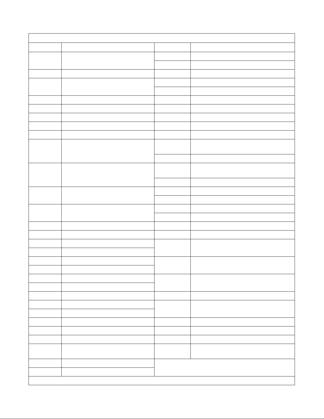
Display Indications for V-Series – Coin
Display Meaning Display Meaning
FC 5 Program identification code (ROM)
(this is an example only)
HoLd Wait...power has just been turned on
PAY/(price)* Pay (flashes alternately with start price if
“FLSH” SETUP option is enabled)
CY Cycle (followed by two-digit number) SUP1 Supply 1
tESt/CYC* Test cycle selected SUP2 Supply 2
FAr Degrees Fahrenheit SUP3 Supply 3
CEL Degrees Celsius SUP5 Supply 5 (supply 1 and 2)
HEAt Auxiliary heat enabled SUP6 Supply 6 (supply 2 and 3)
noHt Auxiliary heat disabled drAI/dISt* Distribution (load balancing before extract)
Strt/A
nt* Start amount – flashes briefly before
showing vend price in Setup Mode
Con1/deno* Coin 1 value – flashes briefly before
showing value of coin 1 in Setup Mode
Con2/deno* Coin 2 value – flashes briefly before
showing value of coin 2 in Setup Mode
PrE Prewash segment (1st of 8 segments) bAL/FAIL* Balance routine failed during test cycle
UASH Wash segment (2nd of 8 segments) SHUT/door* Door not properly closed
FIL1 First fill (3rd of 8 segments) CANt/OPEN* Computer cannot unlock door after five
FIL2 Second fill (4th of 8 segments)
FIL3 Third fill (5th of 8 segments) FILL/STOP* Programmed water level not reached after
FIL4 Fourth fill (6th of 8 segments)
FIL5 Fifth fill (7th of 8 segments) FULL The computer detects low water level or higher
FIL6 Sixth fill (8th of 8 segments)
AFIL Auxiliary fill dFLt Drive fault detected (Variable-speed only)
bFIL Warm fill (both hot and cold) tSFL Temperature sensor failure or temperature out
CFIL Cold fill
bLCH Add bleach (for supply 2 only) bAL? Special factory balance setup mode
1Pr One vend price – all cycles SPC? Special factory valve flush mode
16Pr 16 vend prices – one per cycle SPIN Spin in test cycle (2 speed only)
CHEC/
CYC*
For Wash speed forward in test cycle
FrEE “Free” cycle option
*Display indications separated by a slash (/) represent an alternating display.
Test cycle selected (same as tESt/CYC) rEv Reverse wash speed in test cycle
HFIL Hot fill
Lo Low water level
nEd Medium water level
HI High water level
SUP0 No supplies
(Variable-speed only)
drAI/For* Drain step (low speed forward in test cycle)
SPIn/tInE* Reads “SPIn” for one second, then “tInE”
followed by time for spin
SdLY Spin coast delay
STOP Stop routine
donE Cycle and stop routine have ended
HI 1 Low spin in test cycle (Variable-speed only)
HI 2 High spin in test cycle (Variable-speed only)
attempts
30 minutes
when none should be present
of range
F232137
Table 2
© Copyright, Alliance Laundry Systems LLC – DO NOT COPY or TRANSMIT
9
Page 12
Operation
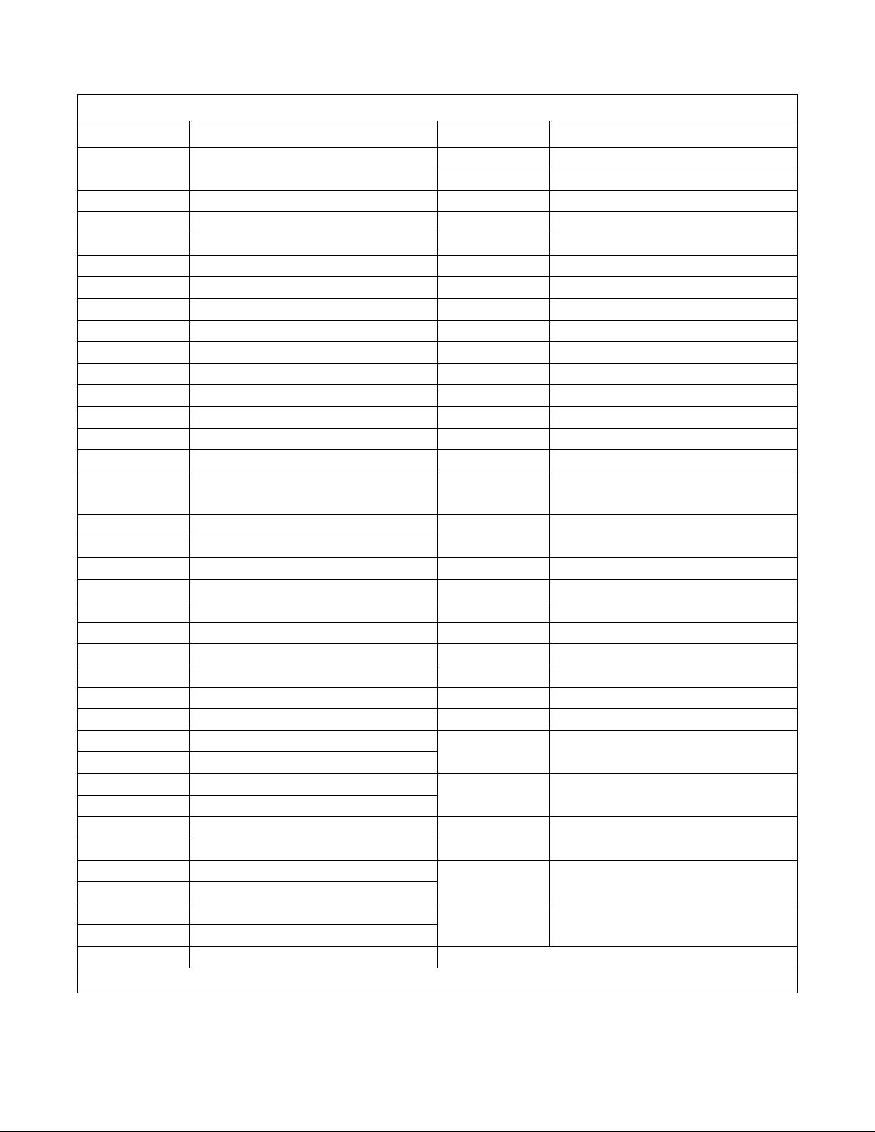
Display Indications for V-Series – Non-Coin
Display Meaning Display Meaning
FP 1 Program identification code (ROM)
(this is an example only)
HoLd Wait...power has just been turned on SUP1 Supply 1
CY Cycle (followed by two-digit number) SUP2 Supply 2
tESt/CYC* Test cycle selected SUP3 Supply 3
FAr Degrees Fahrenheit SUP4 Supply 4
CEL Degrees Celsius SUP5 Supply 5 (Setup option)
HEAt Auxiliary heat enabled SUP6 Supply 6 (supply 1 and 5)
noHt Auxiliary heat disabled SUP7 Supply 7 (supply 3 and 4)
tFIL Temperature-controlled fill enabled SLo/For Gentle wash speed, forward direction
ntFL Temperature-controlled fill disabled SLo/rEv Gentle wash speed, reverse direction
CooL Automatic cool-down enabled nor
noCL Automatic cool-down disabled nor
Ag 1 Agitation 1 selected (90% agitation) drAI Drain enabled
Ag 2 Agitation 2 selected (33% agitation) nodr Drain disabled
Ag 3 Agitation 3 selected (10% agitation) dISt Distribution (load balancing before
Ag 4 Agitation 4 selected (6.7% agitation) SPIn/tI
AgSn Agitation speed normal
AgSL Agitation speed low SPn1 Lowest of three spins
PU
nP Pump output enabled (future use only) SPn2 Middle of three spins
nP
nP Pump output disabled (future use only) SPn3 Highest of three spins
PrE Prewash segment (1st of 11 segments) STOP Stop routine
UASH Wash segment (2nd of 11 segments) SdLY Spin coast delay
FIL1 First fill (3rd of 11 segments) donE Cycle and stop routine have ended
FIL2 Second fill (4th of 11 segments) dFLt Drive fault detected
FIL3 Third fill (5th of 11 segments) door Door not properly closed
FIL4 Fourth fill (6th of 11 segments) bAL/FAIL* Balancing routine failed during test cycle
FIL5 Fifth fill (7th of 11 segments)
FIL6 Sixth fill (8th of 11 segments) FILL/STOP* Programmed water level not reached
FIL7 Seventh fill (9th of 11 segments)
FIL8 Eighth fill (10th of 11 segments) FULL The computer detects low water level or
FIL9 Ninth fill (11th of 11 segments)
CFIL Cold fill rotA Computer detects possible rotation of
bFIL Warm fill (both hot and cold)
HFIL Hot fill tSFL Temperature sensor failure or
AFIL Auxiliary fill (Setup option)
Lo Low water level
*Display indications separated by a slash (/) represent a flashing display.
nEd Medium water level
HI High water level
n/For Normal wash speed, forward direction
n/rEv Normal wash speed, reverse direction
extract)
nE* Reads “SPIn” for one second, then
nE” followed by time for spin
“tI
after 10 attempts to balance load
after 30 minutes
higher when none should be present
motor when there should be none
temperature out of range
10
Table 3
© Copyright, Alliance Laundry Systems LLC – DO NOT COPY or TRANSMIT
F232137
Page 13
Display Indications for V-Series Two Speed – Non-Coin
Display Meaning Display Meaning
Operation
F23n Program identification code (ROM)
(this is an example only)
HoLd Wait...power has just been turned on FIL8 Eighth fill (10th of 11 segments)
CY Cycle (followed by two-digit number) FIL9 Ninth fill (11th of 11 segments)
tESt/CYC* Test cycle selected CFIL Cold fill
FAr Degrees Fahrenheit bFIL Warm fill (both hot and cold)
CEL Degrees Celsius HFIL Hot fill
HEAt Auxiliary heat enabled AFIL Auxiliary fill (Setup option)
noHt Auxiliary heat disabled Lo Low water level
tFIL Temperature-controlled fill enabled
ntFL Temperature-controlled fill disabled HI High water level
CooL Automatic cool-down enabled SUP1 Supply 1
noCL Automatic cool-down disabled SUP2 Supply 2
Ag 1 Agitation 1 selected (90% agitation) SUP3 Supply 3
Ag 2 Agitation 2 selected (33% agitation) SUP4 Supply 4
Ag 3 Agitation 3 selected (10% agitation) SUP5 Supply 5 (or Setup option)
Ag 4 Agitation 4 selected (6.7% agitation) SUP6 Supply 6 (supply 1 and 5)
FIL6 Sixth fill (8th of 11 segments)
FIL7 Seventh fill (9th of 11 segments)
nEd Medium water level
PU
nP Pump output enabled (future use only) SUP7 Supply 7 (supply 3 and 4)
nP Pump output disabled (future use only) For Wash speed, forward direction
nP
PrE Prewash segment (1st of 11 segments) rEv Wash speed, reverse direction
UASH Wash segment (2nd of 11 segments) drAI Drain enabled
FIL1 First fill (3rd of 11 segments) nodr Drain disabled
FIL2 Second fill (4th of 11 segments) STOP Stop routine
FIL3 Third fill (5th of 11 segments) SdLY Spin coast delay
FIL4 Fourth fill (6th of 11 segments) donE Cycle and stop routine have ended
FIL5 Fifth fill (7th of 11 segments) door Door not properly closed
FULL The computer detects low water level or
higher when none should be present
tSFL Temperature sensor failure or
temperature out of range
*Display indications separated by a slash (/) represent a flashing display.
FILL/STOP* Programmed water level not reached
after 30 minutes
SPIn/tI
nE* Reads “SPIn” for one second, then
nE” followed by time for spin
“tI
Table 4
F232137
© Copyright, Alliance Laundry Systems LLC – DO NOT COPY or TRANSMIT
11
Page 14
Operation
Operating Instructions
1. Turn on main power source (circuit breaker).
For non-coin models: Turn on the On/Off switch
on the front panel to the On position.
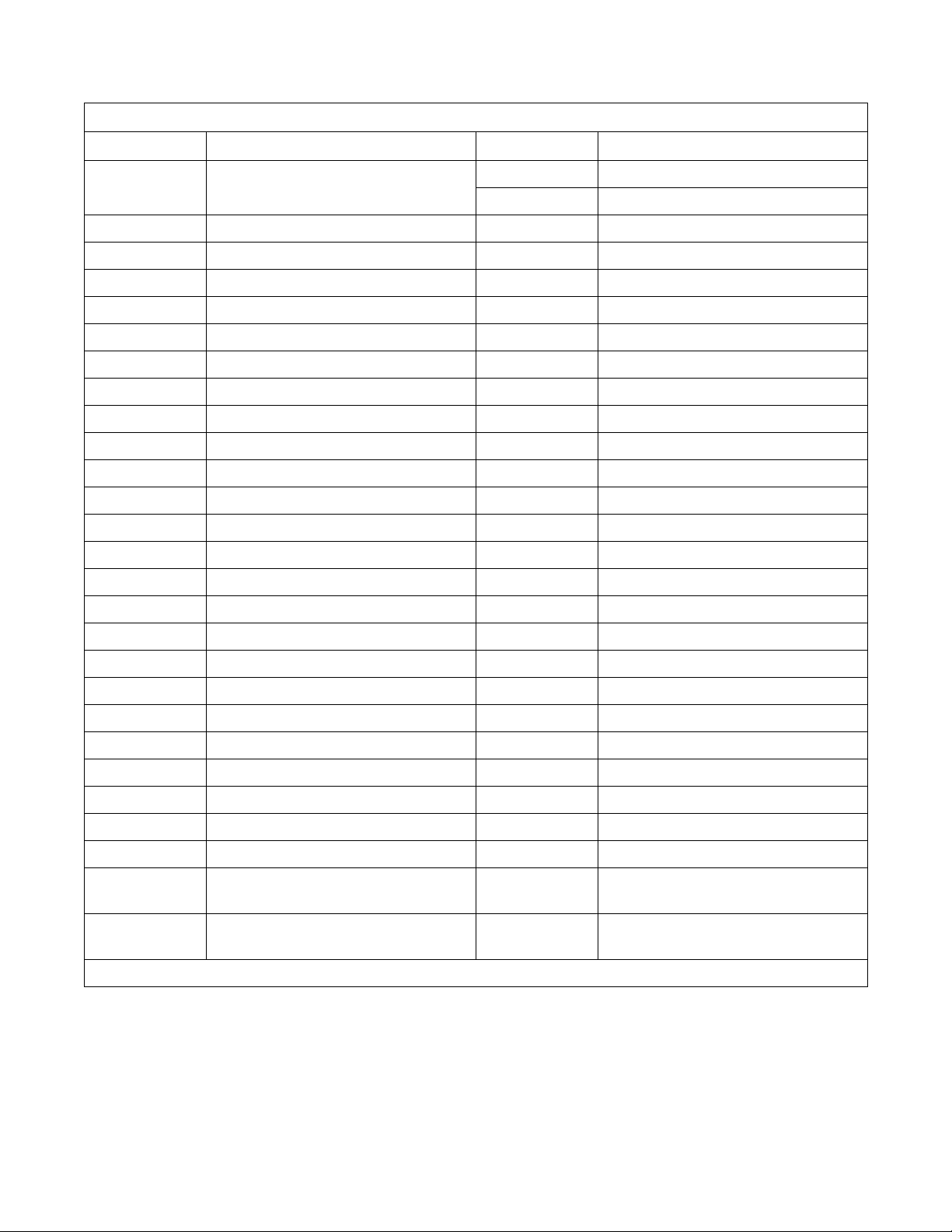
2. Push button and turn handle clockwise to open.
Refer to Figure 3.
U001I
Figure 3
For non-coin models: Press and hold the DOOR
UNLOCK button on the left side of the control
panel while performing the above step. Refer to
Figure 3 and Figure 4.
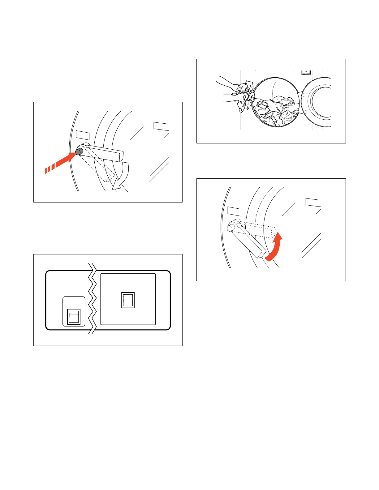
3. Load to capacity whenever possible. DO NOT
OVERLOAD. Refer to Figure 5.
U003I
Figure 5
4. Close door and turn handle counterclockwise
until button pops out. Refer to Figure 6.
U001I
DOOR UNLOCK
Figure 4
U005I
U005I
On
Off
U135R
U135R
Figure 6
12
© Copyright, Alliance Laundry Systems LLC – DO NOT COPY or TRANSMIT
F232137
Page 15

Operation
5. Add liquid and/or powder supplies to supply
dispenser. Refer to Figure 7.
a. Add detergent to container 1.
b. Add softener to container 3.
For non-coin models: Liquid supplies may be
injected directly into the supply dispenser by an
external chemical supply dispenser. Refer to
Installation and Programming Manuals.
6. Press the Up or Down key to select wash cycle.
Press the Start key. Refer to Figure 8.
B157R
Figure 7
7. For coin models: Insert required number of coins
to start machines. Refer to Figure 7.
9. When applicable, add bleach to container 2
when the display reads “bLCH”. Refer to
Figure 9.
CYCLE SELECTION
Up Down Start Stop
U152R
Figure 9
NOTE: To stop a cycle at any time, press the Stop
(non-coin models only) key.
NOTE: To display the temperature of the water
while a cycle is running, press the Up key. To
display the number of the cycle in progress, press
the Start key.
8. For non-coin models: Press the Start key.
Refer to Figure 8.
CYCLE SELECTION
Up Down Start Stop
Figure 8
U137R
F232137
© Copyright, Alliance Laundry Systems LLC – DO NOT COPY or TRANSMIT
13
Page 16

Notes
14
© Copyright, Alliance Laundry Systems LLC – DO NOT COPY or TRANSMIT
F232137
Page 17

Maintenance
Sharp Edges. Can cause personal injury.
Wear safety glasses and gloves, use
proper tools and provide lighting when
handling sheet metal parts.
W366
WARNING
4. Check door interlock before starting operation:
a. Attempt to start the machine with the door
open. The machine should not start with the
door open.
b. Close the door without locking it and attempt
to start the machine. The machine should not
start with the door unlocked.
IMPORTANT: Replace all panels that are removed
to perform service and maintenance procedures.
Do not operate the machine with missing guards or
with broken or missing parts. Do not bypass any
safety devices.
Daily
IMPORTANT: Door lock should be checked daily
to ensure proper operation. Also check that all
safety and instruction labels are on the machine.
Any missing or illegible safety instructions labels
should be replaced immediately.
Beginning of Day
1. Inspect water inlet valve hose connections on the
back of the machine for leaks.
2. Inspect steam hose connections for leaks (where
applicable).
3. Verify that insulation is intact on all external
wires and that all connections are secure. If
exposed wire is evident, call a service technician.
c. Close and lock the door, and start a cycle.
Attempt to open the door while the cycle is in
progress. The door should not open.
If the door lock and interlock are not functioning
properly, call a service technician.
End of Day
1. Clean the door gasket of residual detergent and
all foreign matter.
2. Clean automatic supply dispenser lid and general
area. Flush dispenser with clean water.
3. Clean the machine’s top, front and side panels
with mild detergent. Rinse with clean water.
4. Leave loading door open at the end of each day to
allow moisture to evaporate.
NOTE: Unload the machine promptly after each
completed cycle to prevent moisture buildup. Leave
loading door open after each completed cycle to
allow moisture to evaporate.
F232137
© Copyright, Alliance Laundry Systems LLC – DO NOT COPY or TRANSMIT
15
Page 18

Maintenance
Weekly
1. For variable-speed models only, clean the AC
drive box filter(s) weekly or more frequently as
needed:
NOTE: If fan filter service indicator light is on, fan
filter must be cleaned immediately to prevent
possible damage. Press thermostat button to reset
indicator light.
a. Open the top cover.
b. Grasp the filter handle and pull straight up to
remove filter.
c. Wash the filter with warm water and allow
filter to air-dry. As an alternative, the filter
may be vacuumed clean.
IMPORTANT: The control module cover and fan
filter must be in place for the fan to properly cool
the AC inverter drive. Failure to observe this
warning will void the warranty and could lead to
expensive AC inverter drive repair.
2. Check the machine for leaks.
a. Start an unloaded cycle to fill the machine.
b. Verify that door and door gasket do not leak.
Monthly
NOTE: Disconnect power to the machine at its
source before performing the monthly maintenance
procedures.
1. Use the following procedures to determine if
V-belt(s) require replacement or adjustment. Call
a qualified service technician in either case.
a. Check V-belt(s) for uneven wear and frayed
edges.
b. For groove-pulley drive systems, verify
alignment by placing a straightedge across
both pulley faces. The straightedge should
make contact with the pulleys in four places.
Refer to Figure 10.
1
4
2
3
c. Verify that the drain valve is operating and
that the drain system is free from obstruction.
If water does not leak out during the first wash
segment, the drain valve is closed and
functioning properly.
H040I
1 Motor
2 Motor Pulley
3 Straightedge
4 Basket Pulley
Figure 10
16
© Copyright, Alliance Laundry Systems LLC – DO NOT COPY or TRANSMIT
F232137
Page 19

c. For flat-pulley drive systems, verify allowable
distance of belt from edge of pulley as shown
in Table 5 below:
Flat-Pulley Alignment
Maintenance
Model
Allowable
Distance from Edge
18 – 40 3/32 in. (2 mm)
50 3/8 in. (10 mm)
Table 5
d. For variable-speed models only, verify that
V-belts are properly tensioned by applying a
set force to the belt and measuring the
deflection to determine the belt tension. Refer
to Table 6 for the acceptable belt tension
1 Deflection
2 Span Length
ranges. Belt tension measurements should be
taken as close to the center of the belt span as
possible. Refer to Figure 11.
Belt Tension Testing for Variable-Speed Models
Model Belt Belt Span Deflection Range
1
2
H039I
Figure 11
Force
Min – Max
35, 40 Motor-Basket 16.9 in. (428 mm) 5/16 – 11/32 in. (7.9 – 8.7 mm) 6.1 – 7.4 lbs. (27 – 33 N)
50 Motor-Basket 16.8 in. (426 mm) 9/32 – 5/16 in. (7.1 – 7.9 mm) 6.1 – 7.4 lbs. (27 – 33 N)
80 Motor-Basket 22.1 in. (561 mm) 15/32 – 1/2 in. (11.9 – 12.7 mm) 4.9 – 7.3 lbs. (21.8 – 31.5 N)
Table 6
F232137
© Copyright, Alliance Laundry Systems LLC – DO NOT COPY or TRANSMIT
17
Page 20

Maintenance
1
2
1 Bearing Grease Fitting
2 Seal Grease Fitting
2. For 80 pound capacity models only, lubricate
bearings and seals each month OR after every
200 hours of operation. Refer to Figure 12.
a. Use a premium-grade lithium-based #2
grease. Never mix two types of grease, such
as petroleum and silicone.
H047I
Figure 12
b. Pump the grease gun slowly, permitting only
the following number of strokes:
● Bearing grease fitting, two strokes
● Seal grease fitting, one stroke
Do not pump the grease gun until grease
comes out of the bearing housing. This can
result in overlubrication, causing damage to
bearings and seals.
18
© Copyright, Alliance Laundry Systems LLC – DO NOT COPY or TRANSMIT
F232137
Page 21

Maintenance
I
3. Remove back panel, and check overflow hose
and drain hose for leaks.
4. Unlock the hinged lid, and check the supply
dispenser hoses and hose connections.
5. Clean inlet hose filter screens:
a. Turn water off and allow valve to cool, if
necessary.
b. Unscrew inlet hose and remove filter screen.
c. Clean with soapy water and reinstall. Replace
if worn or damaged.
6. Tighten motor mounting bolt locknuts and
bearing bolt locknuts, if necessary.
7. Use compressed air to clean lint from motor.
8. Clean interior of machine, both basket and shell,
by wiping with a water-soaked sponge or cloth.
9. Use compressed air to ensure that all electrical
components are free of moisture and dust.
10. For variable-speed models only, clean AC drive
cooling fan blades monthly (more often if
required by the condition of the air).
4. Check all painted surfaces for exposed metal.
(Matching paint is available from the
manufacturer.)
● If exposed metal is showing, paint with primer
or solvent-based paint.
● If rust appears, remove it with sandpaper or by
chemical means. Then paint with primer or
solvent-based paint.
5. Clean customer-supplied steam filter, where
applicable. Refer to Figure 13.
a. Turn off steam supply and allow time for the
valve to cool.
b. Unscrew cap.
c. Remove filter element and clean.
d. Replace filter element and cap.
a. Open the top cover and remove the control
module cover.
b. Gently wipe the fan blades clean with a dry
cloth.
Quarterly
NOTE: Disconnect power to the machine before
performing the quarterly maintenance procedures.
1. Tighten door hinges and fasteners, if necessary.
2. Tighten anchor bolts, if necessary.
3. Verify that the drain motor shield is in place and
secure.
1
2
H042
H042I
1 Cap
2 Filter Element
Figure 13
F232137
© Copyright, Alliance Laundry Systems LLC – DO NOT COPY or TRANSMIT
19
Page 22

Maintenance
Care of Stainless Steel
● Remove dirt and grease with detergent and water.
Thoroughly rinse and dry after washing.
● Avoid contact with dissimilar metals to prevent
galvanic corrosion when salty or acidic solutions
are present.
● Do not allow salty or acidic solutions to
evaporate and dry on stainless steel. Wipe clean
of any residues.
● Rub in the direction of the polish lines or “grain”
of the stainless steel to avoid scratch marks when
using abrasive cleaners. Use stainless steel wool
or soft, non-metal bristle brushes. Do not use
ordinary steel wool or steel brushes.
● Remove discoloration or heat tint from
overheating by scouring with a powder or by
employing special chemical solutions.
● Do not leave sanitizers or sterilizing solutions on
stainless steel equipment for prolonged periods
of time.
● When an external chemical supply is used, ensure
no siphoning of chemicals occurs when the
washer-extractor is not in use. Highly
concentrated chemicals can cause severe damage
to stainless steel and other components with the
machine. Damage of this kind is not covered by
the manufacturer’s warranty. Locate the pump
below the washer-extractor’s injection point to
prevent siphoning of chemicals into the machine.
● If the stainless steel appears to be rusting, the
source of the rust may actually be an iron or steel
part not made of stainless steel, such as a nail or
screw. Tip: Paint all carbon steel parts with a
heavy protective coating. Stainless steel fasteners
should be used whenever possible.
20
© Copyright, Alliance Laundry Systems LLC – DO NOT COPY or TRANSMIT
F232137
Page 23

Lavadoras
extractoras
de montaje permanente con
Micro-computadoras de las Series S, P, y V
modelos con tragamonedas y sin tragamonedas
Consulte la página 25 para la identificación de modelos
Operación/mantenimiento
Guarde estas instrucciones para referencia en el futuro.
(Si la unidad cambia de dueño, asegúrese de que este manual vaya con la misma).
www.comlaundry.com
CHM166C
Pieza No. F232137R2
Abril 2002
Page 24

Page 25

Contenido
Introducción ........................................................................................ 25
Identificación de modelos..................................................................... 25
Localización de la placa de identificación............................................ 26
Piezas de repuesto................................................................................. 26
Servicio al cliente ................................................................................. 26
Información de seguridad.................................................................. 27
Instrucciones de seguridad importantes................................................ 27
Operación ............................................................................................ 29
Tablero de control................................................................................. 29
Indicaciones en pantalla........................................................................ 30
Instrucciones de operación ................................................................... 37
Mantenimiento .................................................................................... 39
Diariamente........................................................................................... 39
Al comenzar la jornada diaria.......................................................... 39
Al terminar la jornada diaria............................................................ 39
Semanalmente....................................................................................... 40
Mensualmente....................................................................................... 40
Trimestralmente.................................................................................... 43
Cuidados al acero inoxidable................................................................ 44
© Copyright 2002, Alliance Laundry Systems LLC
Reservados todos los derechos. Ninguna sección del presente manual puede ser reproducida o transmitida en forma
alguna o a través de ningún medio sin el expreso consentimiento por escrito del editor.
F232137 (SP)
© Copyright, Alliance Laundry Systems LLC – DO NOT COPY or TRANSMIT
23
Page 26

Notas
24
© Copyright, Alliance Laundry Systems LLC – DO NOT COPY or TRANSMIT
F232137 (SP)
Page 27

Introducción
Identificación de modelos
La información contenida en este manual es aplicable
a los siguientes modelos:
HC18SN2 HC27VX2 HC50SN2 SC35VN2 UC20PN2 UC40VN2
HC18VC2 HC30SN2 HC50VC2 SC35VNV UC20VN2 UC40VNV
HC18VX2 HC30VC2 HC50VX2 SC40VN2 UC27PN2 UC50PN2
HC20SN2 HC30VX2 HC80VCV SC40VNV UC27VN2 UC50VN2
HC20VC2 HC35SN2 HC80VNV SC50VN2 UC30PN2 UC50VNV
HC20VX2 HC35VC2 HC80VXV SC50VNV UC30VN2 UC80VNV
HC25VC2 HC35VX2 SC18VN2 SC80VNV UC35PN2 UC125VNV
HC25VX2 HC40SN2 SC20VN2 SC125VNV UC35VN2
HC27SN2 HC40VC2 SC27VN2 UC18PN2 UC35VNV
HC27VC2 HC40VX2 SC30VN2 UC18VN2 UC40PN2
F232137 (SP)
© Copyright, Alliance Laundry Systems LLC – DO NOT COPY or TRANSMIT
25
Page 28

Introducción
Localización de la placa de
identificación
La placa de identificación está ubicada en la parte
posterior de la máquina y en el interior de la puerta.
Siempre proporcione el número de serie y el modelo
de la máquina al solicitar piezas o asistencia técnica.
1
Piezas de repuesto
Si necesita documentación o piezas de repuesto,
póngase en contacto con el lugar donde haya adquirido
la máquina o con Alliance Laundry Systems al
(920) 748-3950 para obtener el nombre y la dirección
de su distribuidor autorizado de piezas de repuesto
más cercano.
Servicio al cliente
Para obtener asistencia técnica, llame a cualquiera de
los siguientes números:
(850) 718-1025
(850) 718-1026
Marianna, Florida U.S.A.
(920) 748-3121
Ripon, Wisconsin U.S.A.
1 Placa de identificación
Figura 1
CHM167R
26
© Copyright, Alliance Laundry Systems LLC – DO NOT COPY or TRANSMIT
F232137 (SP)
Page 29

Información de seguridad
PELIGRO indica la presencia de un
peligro que, de ignorarse, ocasionará
lesiones graves, la muerte o daños
considerables a la propiedad.
PELIGRO
ADVERTENCIA indica la presencia de un
peligro que, de ignorarse, puede
ocasionar lesiones graves, la muerte o
daños considerables a la propiedad.
ADVERTENCIA
PRECAUCIÓN indica la presencia de un
peligro que, de ignorarse, puede
ocasionar lesiones menores o daños
considerables a la propiedad.
PRECAUCIÓN
En este manual, así como en las calcomanías adheridas
a la máquina, se incluyen avisos de precaución
(“PELIGRO”, “ADVERTENCIA” y
“PRECAUCIÓN”) seguidos de instrucciones
específicas. Estos avisos tienen como objetivo la
seguridad del operador, del usuario, del técnico de
servicio y de las personas encargadas del
mantenimiento de la máquina.
Instrucciones de seguridad
importantes
ADVERTENCIA
Para reducir el peligro de incendio,
descarga eléctrica, y lesiones personales
graves o incluso letales al utilizar la
lavadora, observe las siguientes medidas
de precaución básicas:
W023SB
1. Lea todas las instrucciones antes de utilizar la
lavadora.
2. Remítase a la sección de Instrucciones para la
conexión a tierra del Manual de instalación para
una correcta conexión a tierra de la lavadora.
3. No lave artículos textiles que se hayan limpiado,
lavado o sumergido en gasolina, solventes para
lavado al seco u otras sustancias inflamables o
explosivas, ya que las mismas despiden gases que
podrían encenderse o causar una explosión.
4. No agregue gasolina, solventes para lavar al seco
u otras sustancias explosivas o inflamables al
agua que utilizará para el lavado. Estas sustancias
despiden vapores que pueden encenderse o
explotar.
Existen otros avisos de precaución (“IMPORTANTE”
y “NOTA”) también seguidos de instrucciones
específicas.
IMPORTANTE: La palabra “IMPORTANTE” se
emplea para informar al lector acerca de
procedimientos específicos que, de no seguirse,
ocasionarán daño a la máquina.
NOTA: La palabra “NOTA” se usa para comunicar
información sobre instalación, operación,
mantenimiento y servicio que, aunque importante,
no representa peligro.
5. En ciertos casos, cuando no se utiliza el sistema
de agua caliente durante dos semanas o más,
puede producirse una acumulación de gas
hidrógeno en dicho sistema. EL GAS
HIDRÓGENO ES EXPLOSIVO. Si no ha
utilizado el sistema de agua caliente durante dos
semanas o más, antes de usar la lavadora o la
combinación de lavadora secadora, abra todos los
grifos del agua caliente y deje que el agua fluya
por ellos durante varios minutos. De esta manera,
se liberará todo el gas hidrógeno acumulado.
Dicho gas es inflamable. No fume ni utilice llama
abierta durante este lapso de tiempo.
6. No deje que los niños jueguen sobre la lavadora
ni dentro de la misma. Debe supervisarse
cuidadosamente a los niños cuando se utiliza la
lavadora cerca de ellos. Esta es una medida de
seguridad aplicable a todos los electrodomésticos.
F232137 (SP)
© Copyright, Alliance Laundry Systems LLC – DO NOT COPY or TRANSMIT
27
Page 30

Información de seguridad
7. Antes de sacar de servicio la lavadora o desecharla,
saque la puerta del compartimiento de lavado.
8. No introduzca la mano en la lavadora si la tina
está en movimiento.
9. No instale ni coloque la lavadora en un lugar
donde esté expuesta al agua o a la intemperie.
10. No utilice inapropiadamente los controles.
11. No repare ni cambie ninguna pieza de la
lavadora, ni trate de hacerle mantenimiento, salvo
que las instrucciones de mantenimiento para el
usuario lo recomienden de manera expresa, o que
lo indiquen las instrucciones de mantenimiento
dirigidas al usuario, que esté en capacidad de
entender y llevar a cabo.
12. Para reducir el riesgo de choque eléctrico o
incendio, NO utilice extensiones ni adaptadores
para conectar la lavadora a la fuente de
suministro de energía eléctrica.
13. Utilice su lavadora sólo para la finalidad con la
que fue fabricada, es decir, para lavar artículos
textiles.
14. Desconecte SIEMPRE la lavadora del tomacorriente
antes de hacerle cualquier mantenimiento. Saque
el cable de suministro de electricidad sujetando el
tomacorriente, en lugar de tirar del cable.
15. Instale la lavadora según se indica en las
Instrucciones de instalación. Todas las
conexiones del suministro de agua, desagüe,
energía eléctrica y conexión a tierra deberán
satisfacer los reglamentos locales y ser realizadas
por personal que cuente con la debida licencia,
cuando el caso lo amerite.
16. Para reducir los riesgos de incendios, no deben
introducirse en la lavadora artículos textiles con
rastros de sustancias inflamables, como por
ejemplo, aceite vegetal, aceite de cocina, aceite
para lubricar máquinas, productos químicos
inflamables, diluyente de pinturas, etc., y prendas
que contengan ceras u otros productos químicos,
tales como mopas y paños de limpieza. Estas
sustancias inflamables pueden provocar que las
telas se prendan en fuego.
17. No utilice suavizadores de ropa o productos para
eliminar la estática, a menos que lo recomiende
el fabricante del suavizador o del producto.
18. Conserve su lavadora en buen estado. Golpear o
dejar caer la lavadora puede dañar los
dispositivos de seguridad. Si esto ocurre, haga
que un técnico de mantenimiento calificado
revise la lavadora.
19. Cambie los cables gastados y los enchufes flojos.
20. Asegúrese de que las conexiones de agua tengan
una válvula de corte y que las conexiones de las
mangueras de llenado estén bien apretadas.
CIERRE las válvulas de corte cuando termine la
jornada diaria.
21. La puerta de carga DEBERÁ ESTAR
CERRADA siempre que la lavadora vaya a
ejecutar un ciclo de llenado, de agitación o de
centrifugado. NO anule el seguro de la puerta de
carga, permitiendo que la lavadora funcione con
la puerta abierta.
22. Lea y siga siempre las instrucciones del fabricante
que aparecen en los paquetes de ayuda para el
lavado y secado. Observe todas las advertencias y
precauciones. Para reducir el riesgo de
envenenamiento o quemaduras con productos
químicos, mantenga en todo momento dichos
productos fuera del alcance de los niños (guárdelos
preferiblemente en un gabinete con llave).
23. Siga siempre las instrucciones para el cuidado de
los artículos textiles, suministradas por el
fabricante de los artículos textiles.
24. Nunca ponga a funcionar la lavadora sin los
protectores o paneles correspondientes.
25. NO utilice la lavadora si le faltan piezas o tiene
piezas dañadas.
26. NO anule ningún dispositivo de seguridad.
27. Si la instalación, mantenimiento u operación de
esta lavadora no se realiza de acuerdo con las
instrucciones del fabricante, es posible que se
originen situaciones peligrosas que podrían
ocasionar lesiones personales y/o daños a la
propiedad.
NOTA: Las INSTRUCCIONES DE SEGURIDAD
IMPORTANTES y ADVERTENCIAS que
aparecen en este manual no pretenden contemplar
todas las posibles condiciones y situaciones que
pueden presentarse. La instalación, mantenimiento
y operación de la lavadora deben hacerse con
sentido común, precaución y cuidado.
Comuníquese con el concesionario, distribuidor,
agente de servicios o fabricante, cuando tenga
problemas o se encuentre en una situación que no
comprenda.
28
© Copyright, Alliance Laundry Systems LLC – DO NOT COPY or TRANSMIT
F232137 (SP)
Page 31

Operación
Up Down Start Stop
5
6
8 7
1
2
3
4
Tablero de control
En la Figura 2 se muestra el tablero de control de las
máquinas equipadas con microcomputadoras serie S,
P y V.
Las teclas Up (Hacia arriba) y
Down (Hacia abajo) se usan para la selección
del ciclo. Presione cualquiera de estas teclas para
desplazarse a través de los ciclos, de menor a mayor,
o de mayor a menor.
La tecla de Start (Arranque) se usa para
iniciar un ciclo.
La tecla de Stop (Parada) no está activa en el
modalidad de funcionamiento normal. En el
modalidad de funcionamiento normal se emplea
únicamente para interrumpir el ciclo de prueba.
La pantalla de LED indica al operador las diferentes
operaciones que se suceden durante la operación de la
máquina. Consulte las tablas que aparecen en las
páginas siguientes, donde se presentan las
indicaciones en pantalla y sus significados. Las luces
indicadoras en la pantalla de LED indican las
condiciones de desbalance y los niveles de agua.
Consulte la Figura 2.
B161R
1 Condición desbalanceada para VCV, VXV
2 Nivel de agua alto
3 Nivel de agua intermedio para serie V
4 Nivel de agua bajo
5 Pantalla de LED
6 Teclas para lavanderías en instalaciones
estándar
7 Teclas para símbolos para lavanderías en
instalaciones
8 Teclas para VC2, VCV, VX2, VXV
Figura 2
F232137 (SP)
© Copyright, Alliance Laundry Systems LLC – DO NOT COPY or TRANSMIT
29
Page 32

Operación
Indicaciones en pantalla
En las tablas siguientes se muestran los diferentes mensajes
que pueden aparecer en pantalla, y lo que significan.
El operador debe familiarizarse con estos mensajes.
Indicaciones en pantalla para máquinas serie S sin tragamonedas
Pantalla Significado Pantalla Significado
S-05 Código de identificación de programa
(ROM) (sólo como ejemplo)
HoLd Espere ... se acaba de encender la
máquina
CY Ciclo (seguido de un número de dos
dígitos)
CHEC/CYC* Ciclo de prueba seleccionado HILE Nivel de agua alto
FAr Grados Fahrenheit SUP1 Suministro 1
CEL Grados Celsius SUP2 Suministro 2
PrE Segmento de prelavado (1ro. de 8
segmentos)
UASH Segmento de lavado (2do. de 8
segmentos)
FIL1 Primer enjuague (3ro. de 8 segmentos) SUP5 Suministro 5 (suministros 1 y 2)
FIL2 Segundo enjuague (4to. de 8 segmentos) SUP6 Suministro 6 (suministros 2 y 3)
FIL3 Tercer enjuague (5to. de 8 segmentos) SUP7 Suministro 7 (suministros 3 y 4)
FIL4 Cuarto enjuague (6to. de 8 segmentos) STOP Rutina de parada
FIL5 Quinto enjuague (7mo. de 8 segmentos) SdLY Retardo de disminución gradual de
bFIL Llenado con agua tibia (ambas, caliente
y fría)
HFIL Llenado con agua caliente
LOLE Nivel de agua bajo
SUP3 Suministro 3
SUP4 Suministro 4
centrifugado
FIL6 Sexto enjuague (8vo. de 8 segmentos) donE Han terminado el ciclo y la rutina de
parada
CFIL Llenado con agua fría door La puerta no está cerrada debidamente.
SPIn/tI
nE* Aparece “SPIn” por un segundo y a
continuación “tI
de centrifugado
tSFL Falla del sensor de temperatura o
temperatura fuera de gama
*Las indicaciones de la pantalla separadas por un guión (/) representan un mensaje alternado.
30
© Copyright, Alliance Laundry Systems LLC – DO NOT COPY or TRANSMIT
nE” seguido del tiempo
FILL/STOP* No se alcanzó el nivel de agua
programado después de 30 minutos
FULL La computadora detecta nivel de agua
bajo o alto cuando no debería detectarse
ninguno
Tabla 1
F232137 (SP)
Page 33

Indicaciones en pantalla para máquinas serie V con tragamonedas
Pantalla Significado Pantalla Significado
Operación
FC 5 Código de identificación de programa
(ROM) (sólo como ejemplo)
HoLd Espere ... se acaba de encender la
máquina
PAY/(price)* Pague (se presenta alternadamente con el
precio de inicio, si está activada la
opción “FLSH” SETUP)
CY Ciclo (seguido de un número de dos
dígitos)
tESt/CYC* Ciclo de prueba seleccionado SUP2 Suministro 2
FAr Grados Fahrenheit SUP3 Suministro 3
CEL Grados Celsius SUP5 Suministro 5 (suministros 1 y 2)
HEAt Activado el calor auxiliar SUP6 Suministro 6 (suministros 2 y 3)
noHt Desactivado el calor auxiliar drAI/dISt* Distribución (balance de carga antes de
Strt/A
nt* Cantidad de inicio – destella
momentáneamente antes de presentar el
precio de la transacción en el modalidad
configuración
HFIL Llenado con agua caliente
Lo Nivel de agua bajo
nEd Nivel de agua intermedio
HI Nivel de agua alto
SUP0 Sin suministros
SUP1 Suministro 1
la extracción) (máquinas con velocidad
variable únicamente)
drAI/For* Paso de desagüe (baja velocidad hacia
adelante en ciclo de prueba)
nE* Aparece “SPIn” por un segundo y a
SPIn/tI
continuación “tI
de centrifugado
SdLY Retardo de disminución gradual de
centrifugado
nE” seguido del tiempo
Con1/deno* Valor de la moneda 1 – destella
momentáneamente antes de mostrar el
valor de la moneda 1 en el modalidad
configuración
Con2/deno* Valor de la moneda 2 – destella
momentáneamente antes de mostrar el
valor de la moneda 2 en el modalidad
configuración
PrE Segmento de prelavado (1ro. de
8 segmentos)
UASH Segmento de lavado (2do. de
8 segmentos)
FIL1 Primer llenado (3ro. de 8 segmentos) CANt/OPEN* La computadora no pudo desbloquear la
FIL2 Segundo llenado (4to. de 8 segmentos)
*Las indicaciones de la pantalla separadas por un guión (/) representan un mensaje alternado.
Tabla 2 (continuación)
STOP Rutina de parada
donE Han terminado el ciclo y la rutina de
parada
HI 1 Centrifugado lento en ciclo de prueba
(máquinas con velocidad variable
únicamente)
HI 2 Centrifugado alto en ciclo de prueba.
(máquinas con velocidad variable
únicamente)
bAL/FAIL* Falló la rutina de balanceo durante el
ciclo de prueba
SHUT/door* La puerta no está cerrada debidamente
puerta tras cinco intentos
F232137 (SP)
© Copyright, Alliance Laundry Systems LLC – DO NOT COPY or TRANSMIT
31
Page 34

Operación
Tabla 2 (continuación)
Indicaciones en pantalla para máquinas serie V con tragamonedas
Pantalla Significado Pantalla Significado
FIL3 Tercer llenado (5to. de 8 segmentos) FILL/STOP* No se alcanzó el nivel de agua
FIL4 Cuarto llenado (6to. de 8 segmentos)
programado después de 30 minutos
FIL5 Quinto llenado (7mo. de 8 segmentos) FULL La computadora detecta nivel de agua
FIL6 Sexto llenado (8vo. de 8 segmentos)
bajo o alto cuando no debería detectarse
ninguno
AFIL Llenado auxiliar dFLt Se detectó falla en el mando (máquinas
con velocidad variable únicamente)
bFIL Llenado con agua tibia (ambas, caliente
y fría)
tSFL Falla del sensor de temperatura o
temperatura fuera de gama
CFIL Llenado con agua fría
bLCH Agregar blanqueador (sólo para
suministro 2)
1Pr Un precio de transacción – todos los
ciclos
bAL? Modalidad de configuración de balanceo
especial de fábrica
SPC? Modalidad de enjuague de válvula
especial de fábrica
16Pr 16 precios de transacción – uno por ciclo SPIN Centrifugado en ciclo de prueba
(máquinas de 2 velocidades únicamente)
CHEC/CYC* Ciclo de prueba seleccionado (igual que
tESt/CYC)
rEv Velocidad de lavado hacia atrás en ciclo
de prueba
For Velocidad de lavado hacia adelante en
ciclo de prueba
FrEE Opción de ciclo “libre”
*Las indicaciones de la pantalla separadas por un guión (/) representan un mensaje alternado.
32
© Copyright, Alliance Laundry Systems LLC – DO NOT COPY or TRANSMIT
F232137 (SP)
Page 35

Indicaciones en pantalla para máquinas serie V sin tragamonedas
Pantalla Significado Pantalla Significado
Operación
FP 1 Código de identificación de programa
(ROM) (sólo como ejemplo)
HoLd Espere ... se acaba de encender la máquina SUP1 Suministro 1
CY Ciclo (seguido de un número de dos dígitos) SUP2 Suministro 2
tESt/CYC* Ciclo de prueba seleccionado SUP3 Suministro 3
FAr Grados Fahrenheit SUP4 Suministro 4
CEL Grados Celsius SUP5 Suministro 5 (opción configuración)
HEAt Activado el calor auxiliar SUP6 Suministro 6 (suministros 1 y 5)
noHt Desactivado el calor auxiliar SUP7 Suministro 7 (suministros 3 y 4)
tFIL Activado el llenado controlado por
temperatura
ntFL Desactivado el llenado controlado por
temperatura
CooL Activado el enfriamiento automático nor
noCL Desactivado el enfriamiento automático nor
Ag 1 Seleccionada la agitación 1
(90% agitación)
nEd Nivel de agua intermedio
HI Nivel de agua alto
SLo/For Velocidad de lavado para prendas
delicadas, sentido hacia adelante
SLo/rEv Velocidad de lavado para prendas
delicadas, sentido hacia atrás
n/For Velocidad de lavado normal, sentido
hacia adelante
n/rEv Velocidad de lavado normal, sentido
hacia atrás
drAI Activado el desagüe
Ag 2 Seleccionada la agitación 2
(33% agitación)
Ag 3 Seleccionada la agitación 3
(10% agitación)
Ag 4 Seleccionada la agitación 4
(6,7% agitación)
AgSn Velocidad de agitación normal
AgSL Velocidad de agitación baja SPn1 Velocidad más baja de los tres
PU
nP Activada la salida de bombeo (sólo para
uso futuro)
nP
nP Desactivada la salida de bombeo (sólo
para uso futuro)
PrE Segmento de prelavado (1ro. de
11 segmentos)
UASH Segmento de lavado (2do. de
11 segmentos)
FIL1 Primer llenado (3ro. de 11 segmentos) donE Han terminado el ciclo y la rutina de parada
FIL2 Segundo llenado (4to. de 11 segmentos) dFLt Se detectó falla en el mando
*Las indicaciones de la pantalla separadas por un guión (/) representan un mensaje alternado.
nodr Desactivado el desagüe
dISt Distribución (balance de carga antes de
la extracción)
SPIn/tI
nE* Aparece “SPIn” por un segundo y a
continuación “TI
de centrifugado
centrifugados
SPn2 Velocidad intermedia de los tres
centrifugados
SPn3 Velocidad más alta de los tres
centrifugados
STOP Rutina de parada
SdLY Retardo de disminución gradual de
centrifugado
nE” seguido del tiempo
F232137 (SP)
Tabla 3 (continuación)
© Copyright, Alliance Laundry Systems LLC – DO NOT COPY or TRANSMIT
33
Page 36

Operación
Tabla 3 (continuación)
Indicaciones en pantalla para máquinas serie V sin tragamonedas
Pantalla Significado Pantalla Significado
FIL3 Tercer llenado (5to. de 11 segmentos) door La puerta no está cerrada debidamente
FIL4 Cuarto llenado (6to. de 11 segmentos) bAL/FAIL* Falló la rutina de balanceo durante el
FIL5 Quinto llenado (7mo. de 11 segmentos)
ciclo de prueba tras 10 intentos de
balancear la carga
FIL6 Sexto llenado (8vo. de 11 segmentos) FILL/STOP* No se alcanzó el nivel de agua
FIL7 Séptimo llenado (9no. de 11 segmentos)
programado después de 30 minutos
FIL8 Octavo llenado (10mo. de 11 segmentos) FULL La computadora detecta nivel de agua
FIL9 Noveno llenado (11mo. de 11 segmentos)
bajo o alto cuando no debería detectarse
ninguno
CFIL Llenado con agua fría rotA La computadora detectó una posible
bFIL Llenado con agua tibia (ambas, caliente
y fría)
rotación del motor cuando éste debería
estar inmóvil
HFIL Llenado con agua caliente tSFL Falla del sensor de temperatura o
AFIL Llenado auxiliar (opción configuración)
temperatura fuera de gama
Lo Nivel de agua bajo
*Las indicaciones de la pantalla separadas por un guión (/) representan un mensaje alternado.
34
© Copyright, Alliance Laundry Systems LLC – DO NOT COPY or TRANSMIT
F232137 (SP)
Page 37

Indicaciones en pantalla para máquinas serie V de dos velocidades sin tragamonedas
Pantalla Significado Pantalla Significado
Operación
F23n Código de identificación de programa
(ROM) (sólo como ejemplo)
HoLd Espere ... se acaba de encender la
máquina
CY Ciclo (seguido de un número de dos
dígitos)
tESt/CYC* Ciclo de prueba seleccionado CFIL Llenado con agua fría
FAr Grados Fahrenheit bFIL Llenado con agua tibia (ambas, caliente
CEL Grados Celsius HFIL Llenado con agua caliente
HEAt Activado el calor auxiliar AFIL Llenado auxiliar (opción configuración)
noHt Desactivado el calor auxiliar Lo Nivel de agua bajo
tFIL Activado el llenado controlado por
temperatura
ntFL Desactivado el llenado controlado por
temperatura
CooL Activado el enfriamiento automático SUP1 Suministro 1
noCL Desactivado el enfriamiento automático SUP2 Suministro 2
Ag 1 Seleccionada la agitación 1
(90% agitación)
FIL6 Sexto llenado (8vo. de 11 segmentos)
FIL7 Séptimo llenado (9no. de 11 segmentos)
FIL8 Octavo llenado (10mo. de 11 segmentos)
FIL9 Noveno llenado (11mo. de
11 segmentos)
y fría)
nEd Nivel de agua intermedio
HI Nivel de agua alto
SUP3 Suministro 3
Ag 2 Seleccionada la agitación 2
(33% agitación)
Ag 3 Seleccionada la agitación 3
(10% agitación)
Ag 4 Seleccionada la agitación 4
(6,7% agitación)
PU
nP Activada la salida de bombeo
(sólo para uso futuro)
nP
nP Desactivada la salida de bombeo (sólo
para uso futuro)
PrE Segmento de prelavado
(1ro. de 11 segmentos)
UASH Segmento de lavado
(2do. de 11 segmentos)
FIL1 Primer llenado (3ro. de 11 segmentos) nodr Desactivado el desagüe
FIL2 Segundo llenado (4to. de 11 segmentos) STOP Rutina de parada
FIL3 Tercer llenado (5to. de 11 segmentos) SdLY Retardo de disminución gradual de
*Las indicaciones de la pantalla separadas por un guión (/) representan un mensaje alternado.
SUP4 Suministro 4
SUP5 Suministro 5 (u opción configuración)
SUP6 Suministro 6 (suministros 1 and 5)
SUP7 Suministro 7 (suministros 3 and 4)
For Velocidad de lavado, sentido hacia
adelante
rEv Velocidad de lavado, sentido hacia atrás
drAI Activado el desagüe
centrifugado
F232137 (SP)
Tabla 4 (continuación)
© Copyright, Alliance Laundry Systems LLC – DO NOT COPY or TRANSMIT
35
Page 38

Operación
Tabla 4 (continuación)
Indicaciones en pantalla para máquinas serie V de dos velocidades sin tragamonedas
Pantalla Significado Pantalla Significado
FIL4 Cuarto llenado (6to. de 11 segmentos) donE Han terminado el ciclo y la rutina de
parada
FIL5 Quinto llenado (7mo. de 11 segmentos) door La puerta no está cerrada debidamente
FULL La computadora detecta nivel de agua
bajo o alto cuando no debería detectarse
ninguno
tSFL Falla del sensor de temperatura o
temperatura fuera de gama
*Las indicaciones de la pantalla separadas por un guión representan un mensaje alternado.
FILL/STOP* No se alcanzó el nivel de agua
programado después de 30 minutos
nE* Aparece “SPIn” por un segundo y a
SPIn/tI
continuación “tI
de centrifugado
nE” seguido del tiempo
36
© Copyright, Alliance Laundry Systems LLC – DO NOT COPY or TRANSMIT
F232137 (SP)
Page 39

Operación
Instrucciones de operación
1. Conecte la alimentación principal (cortacircuitos).
En los modelos sin tragamonedas: Coloque en
la posición On (Encendido) el conmutador de
encendido ubicado en el tablero frontal.
2. Para abrir, oprima el botón y gire la manija en
sentido de las agujas del reloj. Consulte la
Figura 3.
U001I
3. Cargue a máxima capacidad siempre que sea
posible. NO SOBRECARGUE LA MÁQUINA.
Consulte la Figura 5.
U003I
Figura 5
4. Cierre la puerta y gire la manija en sentido
contrario a las agujas del reloj hasta que salga el
botón. Consulte la Figura 6.
U001I
Figura 3
En los modelos sin tragamonedas: Oprima y
mantenga oprimido el botón de DOOR
UNLOCK (Desbloqueo de puerta) ubicado en el
lado izquierdo del panel de control mientras que
realiza el paso anterior. Consulte la Figura 3 y la
Figura 4.
On
DOOR UNLOCK
Off
U135R
U135R
Figura 4
U005I
U005I
Figura 6
F232137 (SP)
© Copyright, Alliance Laundry Systems LLC – DO NOT COPY or TRANSMIT
37
Page 40

Operación
5. Agregue suministros líquidos o en polvo al
surtidor de suministros. Consulte la Figura 7.
a. Agregue detergente al contenedor 1.
b. Agregue suavizador al contenedor 3.
En los modelos sin tragamonedas: Los
suministros líquidos pueden inyectarse
directamente en el surtidor de suministros a través
de un surtidor de suministros externo de productos
químicos. Consulte los manuales de instalación y
programación.
6. Presione la tecla de desplazamiento Up (Hacia
arriba) o de desplazamiento Down (Hacia abajo)
para seleccionar el ciclo de lavado. Oprima el
botón de Start (Arranque). Consulte la Figura 8.
9. Si corresponde, agregue blanqueador al
contenedor 2 cuando aparezca en pantalla
“bLCH”. Consulte la Figura 9.
CYCLE SELECTION
Up Down Start Stop
U152R
Figura 9
NOTA: Para detener un ciclo en cualquier
momento, presione la tecla Stop (Parada) (modelos
sin tragamonedas solamente).
B157R
B157R
Figura 7
7. En modelos con tragamonedas: Inserte la
cantidad requerida de monedas para arrancar la
máquina. Consulte la Figura 7.
8. En modelos sin tragamonedas: Presione la tecla
de Start (Arranque). Consulte la Figura 8.
CYCLE SELECTION
Up Down Start Stop
NOTA: Para visualizar la temperatura del agua
mientras que se ejecuta el ciclo, presione la tecla de
desplazamiento Up (Hacia arriba). Para visualizar
el número del ciclo que se encuentra en ejecución,
presione la tecla de Start (Arranque).
38
U137R
Figura 8
© Copyright, Alliance Laundry Systems LLC – DO NOT COPY or TRANSMIT
F232137 (SP)
Page 41

Mantenimiento
Bordes filosos. Pueden causar lesiones.
Use lentes de seguridad y guantes; use
las herramientas adecuadas y disponga
de suficiente iluminación cuando
manipule piezas elaboradas con láminas
metálicas.
W366S
ADVERTENCIA
IMPORTANTE: Reinstale todos los paneles que se
hayan retirado para efectuar procedimientos de
servicio y mantenimiento. No opere la máquina si
no tiene instalados los protectores, o si faltan piezas
o están dañadas. No anule ningún dispositivo de
seguridad.
Diariamente
IMPORTANTE: Diariamente debe verificarse
que la puerta se bloquee debidamente a fin de
garantizar una operación adecuada. También
debe verificarse que las etiquetas de seguridad
y de instrucciones estén sobre la máquina. Toda
etiqueta de seguridad o de instrucciones que falte o
que sea ilegible deberá reemplazarse
inmediatamente.
Al comenzar la jornada diaria
1. Inspeccione las conexiones de la válvula de
entrada de agua ubicadas por la parte posterior de
la máquina en busca de fugas.
2. Inspeccione las conexiones de mangueras en
busca de fugas (cuando corresponda).
3. Verifique que el aislamiento está intacto en todos
los cables externos y que todas las conexiones
están firmemente aseguradas. De encontrar un
alambre con el aislamiento dañado, llame a un
técnico de servicio.
4. Compruebe el funcionamiento del interruptor de
seguridad de la puerta antes de iniciar la
operación:
a. Intente arrancar la máquina con la puerta
abierta. No deberá poder arrancar la máquina
con la puerta abierta.
b. Cierre la puerta sin bloquearla e intente
arrancar la máquina. No deberá poder
arrancar la máquina con la puerta
desbloqueada.
c. Cierre y bloquee la puerta, e inicie un ciclo.
Intente abrir la puerta en medio del ciclo. No
deberá poder abrir la puerta.
Si el bloqueador de la puerta o el interruptor de
seguridad no funcionan adecuadamente, llame al
técnico de servicio.
Al terminar la jornada diaria
1. Limpie el empaque de la puerta para quitar todos
los residuos de detergente y de partículas
extrañas.
2. Limpie la tapa del surtidor automático de
suministros y el área en general. Enjuague el
surtidor con agua limpia.
3. Limpie la parte de arriba y la parte frontal de la
máquina así como los paneles laterales con un
detergente suave. Enjuague con agua limpia.
4. Deje abierta la puerta de carga al final del la
jornada de trabajo para dejar que se evapore la
humedad.
NOTA: Saque la ropa de la máquina tan pronto
como sea posible después de que termine cada ciclo
de lavado para evitar que se acumule humedad.
Deje abierta la puerta de carga después de
completado el ciclo, para dejar que se evapore la
humedad.
F232137 (SP)
© Copyright, Alliance Laundry Systems LLC – DO NOT COPY or TRANSMIT
39
Page 42

Mantenimiento
Semanalmente
1. En modelos de velocidad variable solamente,
limpie el filtro o los filtros de la caja de mando de
CA semanalmente o con más frecuencia, según
sea necesario:
NOTA: Si se enciende la luz indicadora de servicio
del filtro, hay que limpiar inmediatamente el filtro
del ventilador para evitar posibles daños. Oprima
el botón del termostato para reinicializar la luz
indicadora.
a. Abra la cubierta superior.
b. Agarre la manija del filtro y tire de ella hacia
arriba para sacar el filtro.
c. Lave el filtro con agua tibia y deje que se
seque al aire. Optativamente, el filtro puede
limpiarse usando una aspiradora.
IMPORTANTE: La cubierta del módulo de control
y el filtro del ventilador han de estar en su lugar
para que el ventilador pueda enfriar debidamente
el mando del inversor de CA. Hacer caso omiso a
esta advertencia anulará la garantía y podría traer
como consecuencia una costosa reparación del
mando del inversor de CA.
Mensualmente
NOTA: Desconecte la fuente de alimentación de la
máquina antes de realizar los procedimientos de
mantenimiento mensual.
1. Realice los siguientes procedimientos para
determinar si las correas en V deben ser
cambiadas o si necesitan ajustes. Llame a un
técnico de servicio calificado en cualquiera de
estos casos.
a. Revise si las correas en V se han desgastado
en forma desigual y si tienen orillas
deshilachadas.
b. En sistemas impulsados por polea de
garganta, verifique la alineación colocando
una regla entre ambas caras de la polea. La
regla deberá hacer contacto con las poleas en
cuatro lugares. Consulte la Figura 10.
1
4
2. Inspeccione la máquina en busca de fugas.
a. Inicie un ciclo sin carga para llegar la
máquina.
b. Verifique que la puerta y el empaque de la
misma no presenten fugas.
c. Verifique que la válvula de desagüe esté
funcionando y que el sistema de desagüe no
tenga ninguna obstrucción. Si no se fuga agua
durante el segmento de primer lavado,
significa que la válvula de desagüe está
cerrada y que funciona correctamente.
2
1 Motor
2 Polea del motor
3 Regla
4 Polea conducida
Figura 10
3
H040I
40
© Copyright, Alliance Laundry Systems LLC – DO NOT COPY or TRANSMIT
F232137 (SP)
Page 43

c. En sistemas de mando por polea lisa,
verifique la distancia permitida de la correa
desde el borde de la polea, según se muestra
en la Tabla 5 siguiente:
Alineación de poleas lisas
Modelo
Distancia permitida
desde el borde
Mantenimiento
1
18 – 40 2 mm (3/32 plg)
50 10 mm (3/8 plg)
Tabla 5
2
d. En modelos de velocidad variable
solamente, verifique que las correas en
V tengan la tensión correcta; aplique para ello
la fuerza especificada a la correa y mida la
1 Deflexión
2 Longitud de la distancia libre entre poleas
deflexión para determinar la tensión de la
correa. Consulte la Tabla 6 siguientes para
determinar las gamas de tensión aceptables
Figura 11
para las correas. Las mediciones de la tensión
de la correa deben tomarse lo más cerca
posible del centro de la distancia libre entre
las poleas de la correa. Consulte la Figura 11.
Prueba de tensión de correa en modelos de velocidad variable
Modelo Correa
35, 40 Motor-cesto 428 mm (16,9 plg) 7,9 – 8,7 mm (5/16 – 11/32 plg) 27 – 33 N (6,1 – 7,4 lb)
Distancia libre
entre poleas
Gama de
deflexión
Fuerza
Mín. – Máx.
H039I
50 Motor-cesto 426 mm (16,8 plg) 7,1 – 7,9 mm (9/32 – 5/16 plg) 27 – 33 N (6,1 – 7,4 lb)
80 Motor-cesto 561 mm (22,1 plg) 11,9 – 12,7 mm (15/32 – 1/2 plg) 21,8 – 31,5 N (4,9 – 7,3 lb)
Tabla 6
F232137 (SP)
© Copyright, Alliance Laundry Systems LLC – DO NOT COPY or TRANSMIT
41
Page 44

Mantenimiento
1
2
1 Grasera de rodamientos
2 Grasera de sellos
2. En modelos de 80 libras de capacidad
solamente, lubrique los rodamientos y sellos
cada mes o cada 200 horas de operación.
Consulte la Figura 12.
a. Use una grasa de alta calidad a base de litio de
grado 2. Nunca mezcle dos tipos de grasa,
como por ejemplo, de petróleo y de silicona.
H047I
Figura 12
b. Bombee la grasa lentamente, y no exceda la
cantidad de aplicaciones siguiente:
● Grasera de rodamiento: dos aplicaciones
● Grasera de sello: una aplicación
No bombee la pistola de aplicación de
grasa hasta que salga grasa de la caja del
rodamiento. De lo contrario, podría
ocasionar una sobrelubricación y dañaría
los rodamientos y los sellos.
42
© Copyright, Alliance Laundry Systems LLC – DO NOT COPY or TRANSMIT
F232137 (SP)
Page 45

Mantenimiento
3. Desmonte el panel posterior, y revise si la
manguera de derrame y la manguera de desagüe
tienen fugas.
4. Quite el seguro a la cubierta con bisagras, y
revise las mangueras del surtidor de suministro y
sus conexiones.
5. Limpie las mallas de filtro de las mangueras de
entrada:
a. Cierre el agua y, si fuera necesario, deje que
se enfríe la válvula.
b. Desenrosque las mangueras de entrada y
saque las mallas de filtro.
c. Límpielas con agua jabonosa y reinstálelas.
Sustitúyalos si están dañados o desgastados.
6. Apriete las contratuercas de los pernos de
montaje del motor y las contratuercas de los
pernos de los rodamientos, si fuera necesario.
7. Use aire comprimido para quitar la pelusa
acumulada en el motor.
8. Limpie el interior de la máquina, tanto el cesto
como la coraza, limpiándolas con una esponja o
con un trapo humedecido en agua.
4. Revise si hay metal a la vista en las superficies
pintadas. (A través del fabricante puede
adquirirse pintura igual a la original).
● Si puede ver el metal, pinte con una base o con
pintura con base de solvente.
● Si aparece oxidación, quítela con lija o con
algún método químico.
Seguidamente, pinte con una base o con
pintura con base de solvente.
5. Limpie el filtro de vapor del cliente, si
corresponde. Consulte la Figura 13.
a. Cierre el suministro de vapor y deje que se
enfríe la válvula.
b. Destornille la tapa.
c. Quite el elemento del filtro y límpielo.
d. Vuelva a colocar el elemento del filtro y la tapa.
9. Use aire comprimido para asegurarse de que
ninguno de los componentes eléctricos tenga
humedad y polvo.
10. En modelos de velocidad variable solamente,
limpie las aspas del ventilador de enfriamiento
del mando de CA mensualmente (o más a
menudo si es necesario debido a las condiciones
del aire).
a. Abra la cubierta superior y retire la cubierta
del módulo de control.
b. Limpie suavemente las aspas del ventilador
con un paño seco.
Trimestralmente
NOTA: Desconecte la fuente de alimentación de la
máquina antes de realizar los procedimientos de
mantenimiento trimestral.
1. Apriete las bisagras y tornillos de la puerta, si es
necesario.
2. Apriete los pernos de anclaje, si fuera necesario.
1
2
H042I
H042I
1 Ta pa
2 Elemento del filtro
Figura 13
3. Verifique que el protector del motor de desagüe
esté en su lugar y firmemente asegurado.
F232137 (SP)
© Copyright, Alliance Laundry Systems LLC – DO NOT COPY or TRANSMIT
43
Page 46

Mantenimiento
Cuidados al acero inoxidable
● Elimine la suciedad y la grasa con detergente y
agua. Enjuague a fondo y seque después de lavar.
● El contacto con metales diferentes debe evitarse
en lo posible, para prevenir la corrosión
galvánica en presencia de soluciones salinas o
ácidas.
● No deberá permitirse que soluciones salinas o
ácidas se evaporen y sequen sobre el acero
inoxidable. Limpie el área para eliminar
cualquier residuo.
● Frote en la dirección de las líneas de pulido o el
“grano” del acero inoxidable para evitar rayarlo
cuando use limpiadores abrasivos. Utilice
estropajo de acero inoxidable o cepillos de cerdas
no metálicas. No use estropajo de acero común ni
cepillos de cerdas de acero.
● La decoloración y las marcas producidas por el
sobrecalentamiento pueden eliminarse
restregando el área afectada con un polvo o
empleando soluciones químicas especiales.
● Las soluciones desinfectantes o esterilizadoras no
deben dejarse por tiempo prolongado en
máquinas de acero inoxidable.
● Cuando se use un surtidor de productos químicos
externo, asegúrese de que no ocurra un efecto de
sifón de ningún producto químico mientras la
lavadora extractora no se esté usando. Los
productos químicos a altas concentraciones
pueden causar daños severos al acero inoxidable
y a otros componentes de la máquina. Los daños
de este tipo no están cubiertos por la garantía del
fabricante. Instale la bomba por debajo del nivel
del punto de inyección a la lavadora extractora
para evitar el efecto de sifón de productos
químicos a la máquina.
● Si llegara a parecer que el acero inoxidable
estuviera oxidándose, la fuente de la oxidación
puede ser alguna pieza de hierro o de acero, no
fabricada de acero inoxidable, tal como un clavo
o un tornillo. Recomendación: pinte todas las
piezas de acero al carbón con un fuerte
recubrimiento protector. Deben usarse tornillos y
tuercas de acero inoxidable siempre que sea posible.
44
© Copyright, Alliance Laundry Systems LLC – DO NOT COPY or TRANSMIT
F232137 (SP)
 Loading...