

Page 1
Washer-Extractor
Cabinet Hardmount
2-Speed, 3-Speed, and Variable-Speed
Model Numbers
HC18 SC18 UC18
HC25 SC25 UC25
HC27 SîC27 UC27
HC35 SC35 UC35
HC50 SC50 UC50
HC80 SC80 UC80
(See inside for complete model number list.)
Installation/Maintenance
NOTA: El manual en
español aparece después
del manual en inglés.
Part No. F232062R4
May 1999
Page 2

Model Number Chart
HC18EC2
HC18MC2
HC18MD2
HC18MH2
HC18MN2
HC18MV2
HC18PC2
HC18SN2
HC18VC2
HC25EC2
HC25MC2
HC25MD2
HC25MH2
HC25MN2
HC25MV2
HC35MD2
HC35MH2
HC35MN2
HC35MV2
HC35PC2
HC35SN2
HC35VC2
HC50EC2
HC50MC2
HC50MD2
HC50MH2
HC50MN2
HC50MV2
HC50PC2
HC50SN2
SC18MC3
SC18MD2
SC18MD3
SC18MH2
SC18MH3
SC18MN2
SC18MN3
SC18MV2
SC18MV3
SC18SN2
SC18SN3
SC18VN2
SC18VNV
SC25EC2
SC25EP2
SC27SN2
SC27VN2
SC27VNV
SC35EC2
SC35EP2
SC35MC2
SC35MC3
SC35MD2
SC35MD3
SC35MH2
SC35MH3
SC35MN2
SC35MN3
SC35MV2
SC35MV3
SC50MN3
SC50MV2
SC50MV3
SC50SN2
SC50VN2
SC50VNV
SC80ECV
SC80EPV
SC80MC3
SC80MD3
SC80MH3
SC80MN3
SC80MV3
SC80SN3
SC80VNV
UC18PN3
UC18VN2
UC18VNV
UC25MC2
UC25MD2
UC25MH2
UC25MN2
UC25MV2
UC25PC2
UC25PN2
UC27MN2
UC27PN2
UC27VN2
UC35MC2
UC35MC3
UC35VNV
UC50MC2
UC50MC3
UC50MD2
UC50MD3
UC50MH2
UC50MH3
UC50MN2
UC50MN3
UC50MV2
UC50MV3
UC50PC2
UC50PC3
UC50PN2
UC50PN3
HC25PC2
HC25SN2
HC25VC2
HC27EC2
HC27MC2
HC27MD2
HC27MH2
HC27MN2
HC27MV2
HC27SN2
HC27VC2
HC35EC2
HC35MC2
HC50VC2
HC80MC3
HC80MD3
HC80MH3
HC80MN3
HC80MV3
HC80PC3
HC80SN3
HC80VCV
HC80VNV
SC18EC2
SC18EP2
SC18MC2
SC25MC2
SC25MD2
SC25MH2
SC25MN2
SC25MV2
SC25SN2
SC27EC2
SC27EP2
SC27MC2
SC27MD2
SC27MH2
SC27MN2
SC27MV2
SC35SN2
SC35SN3
SC35VN2
SC35VNV
SC50EC2
SC50EP2
SC50MC2
SC50MC3
SC50MD2
SC50MD3
SC50MH2
SC50MH3
SC50MN2
UC18MC2
UC18MC3
UC18MD2
UC18MD3
UC18MH2
UC18MH3
UC18MN2
UC18MN3
UC18MV2
UC18MV3
UC18PC2
UC18PC3
UC18PN2
UC35MD2
UC35MD3
UC35MH2
UC35MH3
UC35MN2
UC35MN3
UC35MV2
UC35MV3
UC35PC2
UC35PC3
UC35PN2
UC35PN3
UC35VN2
UC50VN2
UC50VNV
UC80MC3
UC80MD3
UC80MH3
UC80MN3
UC80MV3
UC80PC3
UC80PN3
UC80VNV
Page 3

Table of Contents
Installation/Maintenance
Safety
Key to Symbols ................................................ 4
Safety Decal Location ...................................... 5
Operator Safety ................................................ 6
Safe Operating Environment ............................ 7
Environmental Conditions ............................ 7
Machine Location ......................................... 8
Input and Output Services ............................ 8
AC Inverter Drive ......................................... 9
Misuse .............................................................. 9
Installation
Machine Overview ........................................... 11
Delivery Inspection .......................................... 12
Customer Service ............................................. 12
Model Number Familiarization Guide ............. 13
General Specifications ..................................... 14
Machine Dimensions ........................................ 20
Dimensional Clearances ................................... 27
Machine Foundation ........................................ 29
Mechanical Installation .................................... 31
Expansion Bolt Installation .......................... 31
Drain Connection ............................................. 42
Water Connection ............................................ 44
Electrical Installation ....................................... 45
Steam Requirements (Steam Heat
Option Only) .................................................... 52
Chemical Injection Supply System .................. 53
Control Function Test ...................................... 57
Maintenance
Daily ................................................................ 59
Beginning Of Day ........................................ 59
End Of Day .................................................. 60
Weekly ............................................................. 60
Monthly ........................................................... 60
Quarterly .......................................................... 64
Care Of Stainless Steel .................................... 65
Maintenance Checklists ................................... 66
Removal from Service
Decommissioning ............................................ 71
Elevated Base Frame Installation ................. 33
J-Bolt Installation ......................................... 35
Concrete Foundation Pad ............................. 39
F232062
1
Page 4

© Copyright 1999 Alliance Laundry Systems LLC
All rights reserved. No part of the contents of this book may be reproduced or transmitted in any form or by any
means without the expressed written consent of the publisher.
F232062
Page 5

Section 1
Death or serious injury can result if children
become trapped in the machine. Do not
allow children to play on or around this
machine. Do not leave children unattended
while the machine door is open.
SW001
DANGER
This machine must be installed, adjusted,
and serviced by qualified electrical
maintenance personnel familiar with the
construction and operation of this type of
machinery. They must also be familiar with
the potential hazards involved. Failure to
observe this warning may result in personal
injury and/or equipment damage, and may
void the warranty.
SW004
WARNING
Safety
Anyone operating or servicing this machine
must follow the safety rules in this manual.
Particular attention must be paid to the
DANGER, WARNING
, and
CAUTION
blocks which appear throughout the manual.
CAUTION
Be careful around the open door,
particularly when loading from a level
below the door. Impact with door edges
can cause personal injury.
SW025
WARNING
Dangerous voltages are present in the
electrical control box(es) and at the motor
terminals. Only qualified personnel familiar
with electrical test procedures, test
equipment, and safety precautions should
attempt adjustments and troubleshooting.
Disconnect power from the machine before
removing the control box cover, and before
attempting any service procedures.
SW005
The following warnings are general examples
that apply to this machine. Warnings specific
to a particular installation or maintenance
procedure will appear in the manual with the
discussion of that procedure.
F232062
3
Page 6
Safety
CAUTION
Ensure that the machine is installed on a
level floor of sufficient strength and that the
recommended clearances for inspection
and maintenance are provided. Never allow
the inspection and maintenance space to
be blocked.
SW020
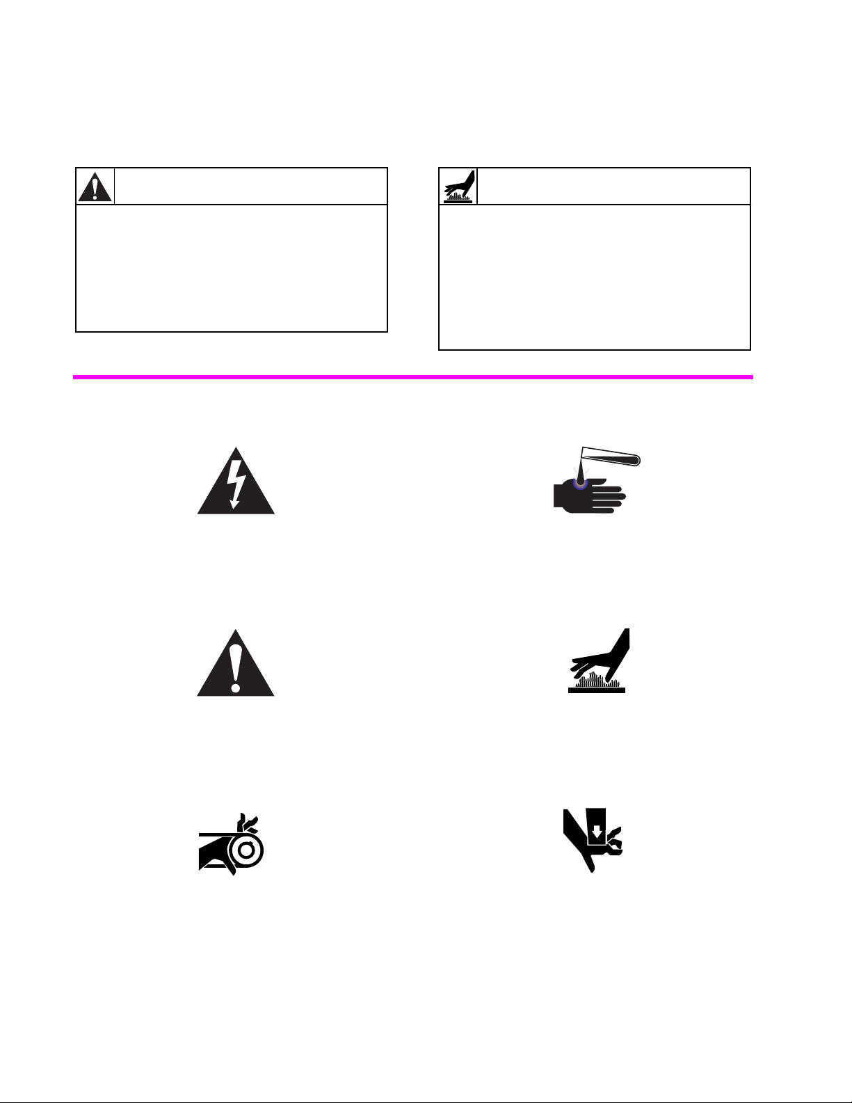
Key To Symbols
The lightning flash and arrowhead within the
triangle is a warning sign indicating the
presence of dangerous voltage.
WARNING
Never touch internal or external steam
pipes, connections, or components. These
surfaces can be extremely hot and will
cause severe burns. The steam must be
turned off and the pipe, connections, and
components allowed to cool before the pipe
can be touched.
SW014
This warning symbol indicates the presence of
possibly dangerous chemicals. Proper
precautions should be taken when handling
corrosive or caustic materials.
The exclamation point within the triangle is a
warning sign indicating important instructions
concerning the machine and possibly
dangerous conditions.
This warning symbol indicates the presence of
potentially dangerous drive mechanisms
within the machine. Guards should always be
in place when the machine is in operation.
4
This warning symbol indicates the presence of
hot surfaces that could cause serious burns.
Stainless steel and steam lines can become
extremely hot and should not be touched.
This warning symbol indicates the presence of
possibly dangerous pinch-points. Moving
mechanical parts can crush and/or sever
body parts.
F232062
Page 7
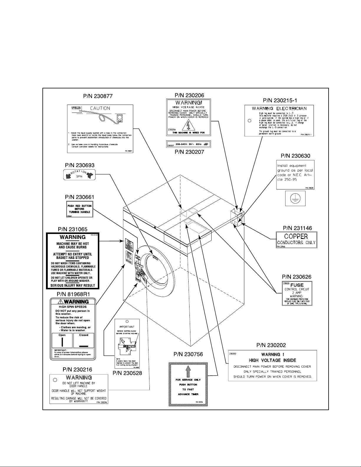
Safety
Safety decals appear at crucial locations on the
machine. Failure to maintain legible safety
(O.P.L. Only)
decals could result in injury to the operator or
service technician.
(Typical)
81968R1
8
1
96
8
R
1
(O.P.L. Only)
(80-pound models only)
(Not present on EDC models)
(MC Models Only)
H018IE3A
F232062
Figure 1
5
Page 8
Safety
To provide personal safety and keep the
machine in proper working order, follow all
maintenance and safety procedures presented
in this manual. If questions regarding safety
arise, contact the factory immediately.
Use factory-authorized spare parts to avoid
safety hazards.
Operator Safety
WARNING
NEVER insert hands or objects into basket
until it has completely stopped. Doing so
could result in serious injury.
SW012
To ensure the safety of machine operators,
the following maintenance checks must be
performed daily:
1. Prior to operating the machine, verify that
all warning signs are present and legible.
Missing or illegible signs must be replaced
immediately. Make certain that spares are
available.
If the door lock and interlock are
not functioning properly, call a
service technician.
3. Do not attempt to operate the machine
if any of the following conditions
are present:
a. The door does not remain securely
locked during the entire cycle.
b. Excessively high water level is evident.
c. Machine is not connected to a properly
grounded circuit.
Do not bypass any safety devices in
the machine.
WARNING
Never operate the machine with a bypassed
or disconnected balance system. Operating
the machine with severe out-of-balance
loads could result in personal injury and
serious equipment damage.
SW039
2. Check door interlock before starting
operation of the machine:
a. Attempt to start the machine with the
door open. The machine should not
start with the door open.
b. Close the door without locking it and
attempt to start the machine. The
machine should not start with the
door unlocked.
c. Close and lock the door and start a
cycle. Attempt to open the door while
the cycle is in progress. The door
should not open.
6
F232062
Page 9

Safety
Do not place volatile or flammable fluids
in any machine. Do not clean the machine
with volatile or flammable fluids such as
acetone, lacquer thinners, enamel reducers,
carbon tetrachloride, gasoline, benzene,
naptha, etc. Doing so could result in serious
personal injury and/or damage to
the machine.
SW002
DANGER
Safe Operating Environment
Safe operation requires an appropriate
operating environment for both the operator
and the machine. If questions regarding safety
arise, contact the factory immediately.
Environmental Conditions
•
Ambient Temperature
machine will freeze at temperatures of
32°F (0°C) or below.
Temperatures above 120°F (50°C) will
result in more frequent motor overheating
and, in some cases, malfunction or
premature damage to solid state devices
that are used in some models. Special
cooling devices may be necessary.
Water pressure switches are affected by
increases and decreases in temperature.
Every 25°F (10°C) change in temperature
will have a 1% effect on the water level.
.
Water in the
periodically. Louvers, screens, or other
separating devices may reduce the
available air opening significantly.
•
Radio Frequency Emissions
.
A filter is
available for machines in installations
where floor space is shared with
equipment sensitive to radio frequency
emissions.
•
Elevation
.
If the machine is to be operated
at elevations of over 3,280 feet (1,000
meters) above sea level, pay special
attention to water levels and electronic
settings (particularly temperature) or
desired results may not be achieved.
•
Chemicals
. Keep stainless steel surfaces
free of chemical residues.
•
Humidity
. Relative humidity above 90%
may cause the machine’s electronics or
motors to malfunction or may trip the
ground fault interrupter. Corrosion
problems may occur on some metal
components in the machine.
If the relative humidity is below 30%, belts
and rubber hoses may eventually develop
dry rot. This condition can result in hose
leaks, which may cause safety hazards
external to the machine in conjunction
with adjacent electrical equipment.
•
Ventilation
openings for such laundry room
accessories as dryers, ironers, water
heaters, etc., must be evaluated
F232062
. The need for make-up air
•
Water Damage
.
Do not spray the machine
with water. Short circuiting and serious
damage may result. Repair immediately all
seepage due to worn or damaged
gaskets, etc.
7
Page 10
Safety
Safe Operating Environment
(Continued)
Machine Location
•
Foundation
. The concrete floor must be of
sufficient strength and thickness to handle
the floor loads generated by the high
extract speeds of the machine.
•
Service/Maintenance Space
.
Provide
sufficient space to allow comfortable
performance of service procedures and
routine preventive maintenance.
This is especially important in connection
with machines equipped with an AC
inverter drive.
Consult installation instructions for specific
details.
CAUTION
Replace all panels that are removed to
perform service and maintenance
procedures. Do not operate the machine
with missing guards or with broken or
missing parts. Do not bypass any
safety devices.
Input and Output Services
•
Water Pressure
. Best performance will be
realized if water is provided at a pressure
of 30 – 85 psi (2.0 – 5.7 bar). Although the
machine will function properly at lower
pressure, increased fill times will occur.
Water pressure higher than 100 psi
(6.7 bar) may result in damage to machine
plumbing. Component failure(s) and
personal injury could result.
SW019
•
Steam Heat (Optional) Pressure
.
Best
performance will be realized if steam is
provided at a pressure of 30 – 80 psi
(2.0 – 5.4 bar). Steam pressure higher
than 125 psi (8.5 bar) may result in
damage to steam components and may
cause personal injury.
For machines equipped with optional
steam heat, install piping in accordance
with approved commercial steam
practices. Failure to install the supplied
steam filter may void the warranty.
•
Compressed Air
.
For machines requiring
compressed air service, best performance
will be realized if air is provided at a
pressure of 80 – 100 psi (5.4 – 6.7 bar).
•
Drainage System
.
Provide drain lines or
troughs large enough to accommodate
the total number of gallons that could
be dumped if all machines on the site
drained at the same time from the highest
attainable level. If troughs are used,
they should be covered to support light
foot traffic.
•
Power
. For personal safety and for proper
operation, the machine must be grounded
in accordance with state and local codes.
The ground connection must be to a
proven earth ground, not to conduit or
water pipes. Do not use fuses in place of
the circuit breaker. An easy-access cutoff
switch should also be provided.
8
F232062
Page 11

WARNING
Ensure that a ground wire from a proven
earth ground is connected to the ground lug
near the input power block on this machine.
Without proper grounding, personal injury
from electric shock could occur and machine
malfunctions may be evident.
SW008
Always disconnect power and water supplies
before a service technician performs any
service procedure. Where applicable, steam
and/or compressed air supplies should also be
disconnected before service is performed.
Safety
installations or above 440V for 400V
installations, a buckboost transformer is
recommended. If voltage is above 240 or
480, a buckboost transformer is required.
•
Sufficient space to perform service
procedures and routine preventive
maintenance is especially important for
machines equipped with the AC
inverter drive.
Misuse
Never use this machine for any purpose other
than washing fabric.
AC Inverter Drive
Machines equipped with the AC inverter drive
require special attention with regard to the
operating environment.
•
An especially dusty or linty environment
will require more frequent cleaning of the
AC inverter drive cooling fan filter and of
the AC inverter drive itself.
•
Power line fluctuations from sources such
as uninterruptible power supplies (UPS)
can adversely affect machines equipped
with the AC inverter drive. Proper
suppression devices should be utilized on
the incoming power to the machine to
avoid problems.
•
A clean power supply free from voltage
spikes and surges is absolutely essential
for machines equipped with the AC
inverter drive. Nonlinear inconsistencies
(peaks and valleys) in the power supply
can cause the AC inverter drive to generate
nuisance errors.
•
Never wash petroleum-soaked rags in the
machine. This could result in an explosion.
•
Never wash machine parts or automotive
parts in the machine. This could result in
serious damage to the basket.
•
Never allow children to play on or around
this machine. Death or serious injury can
result if children become trapped in the
machine. Do not leave children unattended
while the machine door is open. These
cautions apply to animals as well.
If voltage is above 230V for 200V
F232062
9
Page 12

Safety
Notes
10
F232062
Page 13

Section 2
Installation
This manual is designed as a guide to the
installation and maintenance of the 18-pound,
25-pound, 27-pound, 35-pound, 50-pound,
and 80-pound capacity cabinet hardmount
washer-extractors.
Machine Overview
The design of the machine emphasizes
performance reliability and long service life.
In washer-extractor sizes up through the
50-pound capacity models, the cylinder is
supported with two sealed bearings mounted in
a machined cast iron trunnion. On 80-pound
capacity models, the cylinder and shaft
assembly is supported by two flange roller
bearing assemblies. Bearing housings are
bolted to a heavy gamma frame.
The 2-speed machines use one dual-speed
motor to drive the cylinder via a V-belt drive in
wash speed and extract speed.
The 3-speed 18-pound capacity models use
one triple-speed motor to drive the cylinder
at wash speed, medium extract speed, and
high extract speed. The 3-speed 35-pound,
50-pound, and 80-pound capacity models use
one single-speed and one dual-speed motor to
drive the cylinder at wash speed, medium
extract speed, and high extract speed.
flat belt drive. The 80-pound capacity machine
uses a 3V belt drive.
A door-lock system prevents opening of the
stainless steel door when a cycle is in progress.
It also prevents operation of the machine when
the door is open.
An electrically operated drain valve is used
to retain the water and wash solution in the
machine during the wash and rinse steps.
The drain valve closes when power is applied
and opens when power is removed, allowing
the machine to drain in the event of a
power failure.
The cylinder is designed with lifters or ribs
that lift the garments from the wash solution
when the cylinder rotates at slow speed and
allow the garments to tumble back into the
solution. The cylinder is perforated, allowing
the water to pass through and drain from
within during the wash process and extract.
Electrical controls for the machine are housed
in a separate enclosure located underneath the
top cover of the machine.
AC drive-controlled washer-extractors use one
motor to drive the cylinder. In all capacities
except the 80-pound, the motor is driven via a
F232062
11
Page 14

Installation
Machine Overview
The polypropylene supply dispenser is
located under a flexible cover on the left side
of the machine, viewed from the front. The
compartments are numbered 1 – 3, starting
from the left side of the machine. A nozzle
flushes dry supplies from the compartment
with water at the appropriate time in the cycle.
Liquid supplies can be injected directly into
the dispenser compartments by a customersupplied external chemical supply system.
Hose barbs on the rear of the machine facilitate
connection to an external chemical supply
system. A terminal strip in the input power
junction box provides control signals.
(Continued)
Delivery Inspection
Upon delivery, visually inspect crate,
protective cover, and unit for any visible
shipping damage. If the crate, protective cover,
or unit are damaged or signs of possible
damage are evident, have the carrier note the
condition on the shipping papers before the
shipping receipt is signed, or advise the carrier
of the condition as soon as it is discovered.
Customer Service
If literature or replacement parts are required,
contact the source from whom the machine
was purchased or contact Alliance Laundry
Systems LLC at (920) 748-3950 for the name
and address of the nearest authorized
parts distributor.
For technical assistance, call any of the
following numbers:
(850) 718-1035
(850) 718-1026
Marianna, Florida
(920) 748-3121
Ripon, Wisconsin
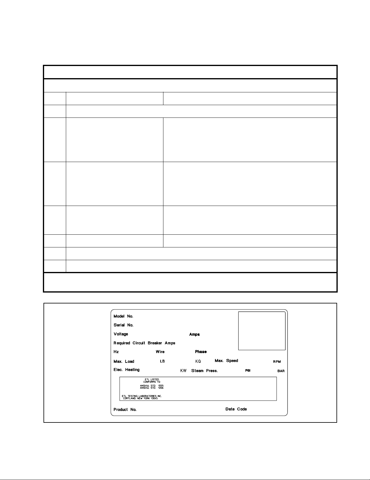
A record of each machine, including the serial
number, is on file with the manufacturer. The
serial number decal is located at the rear of the
machine. See Figure 2. Always provide the
machine’s serial number and model number
when ordering parts or when seeking
technical assistance.
Remove the crate and protective cover as soon
after delivery as possible. If any damage is
discovered upon removal of the crate and/or
protective cover, advise the carrier and file a
written claim immediately.
12
F232062
Page 15
Model Number Familiarization Guide
Installation
SC
35
M
(E)
(P)
(S)
(V)
N
(C)
(D)
(H)
(V)
2
(3)
(V)
C
U2
Sample Model Number:
Machine Type C = Cabinet
Machine Capacity (pounds dry weight)
Type of Electrical Control M = Mechanical Timer
E = WX/EDC Microcomputer
P = P-Series Microcomputer†
S = S-Series Microcomputer
V = V-Series Microcomputer
Coin Meter Option N = No Coin Meter
C = W2000 (Computer-controlled models only)‡
D = Digital (Mechanical Timer models only)
H = Horizontal Slide (Mechanical Timer models only)
V = Vertical Drop (Mechanical Timer models only)
Speed 2 = 2-Speed
3= 3-Speed
V = Variable-Speed
Electrical Characteristics See Voltage Designation Chart in this section.
Design Series
SC35MN2CU20001
0001
†Models designated “PN” use the S-Series Microcomputer.
‡Models designated “MC” are prepared for use with an aftermarket coin meter.
Option Identification (varies from machine to machine)
SC35MN2CU20001
00000000000
380 – 415
50
15
43
35 16
500000
Figure 2
5
470
H043I
F232062
13
Page 16

Installation
Cabinet Hardmount General Specifications
2-Speed Models
Specification 18 25 27 35 50
Overall Dimensions
Overall width, in (mm) 26 (660) 26 (660) 29 (737) 30-1/8 (765) 34-1/16 (865)
Overall height, in (mm) 42 (1067) 45 (1143) 45 (1143) 47-1/4 (1200) 49-3/4 (1265)
Overall depth, in (mm) 29-11/16
(754)
Weight and Shipping Information
Net weight, lb (kg) 390 (177) 435 (198) 495 (225) 650 (295) 820 (373)
Domestic shipping weight, lb (kg) 430 (194) 475 (214) 555 (250) 710 (320) 970 (437)
3
(m3)
3
(m3)
Domestic shipping volume, ft
Export shipping weight, lb (kg) 480 (218) 525 (236) 605 (272) 760 (345) 1020 (464)
Export shipping volume, ft
Cylinder diameter, in (mm) 21 (533) 21 (533) 24 (610) 26-1/4 (667) 30 (762)
Cylinder depth, in (mm) 13-3/4 (349) 18-3/4 (457) 16 (406) 18-3/8 (467) 20 (508)
Cylinder volume, ft
Perforation size, in (mm) 0.188 (4.76) 0.188 (4.76) 0.188 (4.76) 0.188 (4.76) 0.188 (4.76)
Perforation open area,% 17 17 23 17 18
3
(l)
23.9 (0.669) 28.9 (0.809) 30.1 (0.852) 39.0 (1.09) 49.8 (1.39)
47.1 (1.32) 35.9 (1.01) 37.7 (1.07) 47.1 (1.32) 68.6 (1.92)
Wash Cylinder Information
2.76 (78.1) 3.76 (106) 4.19 (117.9) 5.76 (163.1) 8.18 (232)
Door Opening Information
33-11/16
(856)
34-13/16
(884)
38-1/2 (978) 42 (1067)
Door opening size, in (mm) 12 (305) 12 (305) 14-11/32
(364)
Ht. door bottom above floor, in
(mm)
Avg. power used per cycle, kW/hr 0.20 0.25 0.25 0.30 0.42
Nominal sound emission, dBA 60 63 63 64 66
Background noise level, dBA 48 51 51 49 49
Average HVAC load, Btu/hr 425 400 400 est. 510 700
14
17-1/4 (438) 17-1/4 (438) 17 (432) 19 (480) 18-1/4 (465)
Power Consumption
13-15/16
(354)
16-1/4 (413)
F232062
Page 17

Installation
Cabinet Hardmount General Specifications
2-Speed Models (Continued)
Specification 18 25 27 35 50
Drive Train Information
Number of motors in drive train 1 1 1 1 1
Wash/reverse power, hp (kW) 0.18 (0.13) 0.25 (0.19) 0.25 (0.19) 0.40 (0.30) 0.55 (0.41)
High extract power, hp (kW) 1.0 (0.746) 1.4 (1.04) 1.4 (1.04) 1.8 (1.3) 2.7 (2.01)
Cylinder Speeds
Wash/reverse speed, rpm 5355474744
High extract speed, rpm 525 540 480 470 450
Centrifugal Force Data
Wash/reverse centrifugal force, Gs 0.85 0.90 0.75 0.82 0.825
High extract centrifugal force, Gs 82.1 86.9 80 82.3 86.3
Balance Detection
Vibration safety switch installed N/A N/A N/A N/A N/A
Direct Steam Heating (Optional)
Steam inlet connection size, in (mm) 1/2 (13) 1/2 (13) 1/2 (13) 1/2 (13) 1/2 (13)
Number of steam inlets 1 1 1 1 1
Steam req. to raise bath
temperature 10°F, l b
(10°C, kg)
Average steam use per cycle, BHP 0.66 0.87 0.94 1.4 1.9
Total electrical heating capacity, kW 7.8 7.8 7.8 15.6 23.4
Electrical heating elements 3 3 3 6 9
Electrical heat element size, kW 2.6 2.6 2.6 2.6 2.6
LOW 1.1 (0.50) 1.4 (0.64) 1.5 (0.68) 2.1 (0.95) 2.8 (1.3)
HIGH 1.2 (0.54) 1.6 (0.73) 1.7 (0.77) 2.8 (1.3) 3.7 (1.7)
Electrical Heating (Optional)
F232062
15
Page 18

Installation
Cabinet Hardmount General Specifications
3-Speed Models
Specification 18 35 50 80
Overall Dimensions
Overall width, in (mm) 26 (660) 30-1/8 (765) 34-1/16 (865) 41-1/2 (1054)
Overall height, in (mm) 42 (1067) 47-1/4 (1200) 49-3/4 (1265) 56 (1422)
Overall depth, in (mm) 29-11/16 (754) 38-1/2 (978) 42 (1067) 51-5/8 (1311)
Weight and Shipping Information
Net weight, lb (kg) 400 (182) 675 (307) 950 (432) 1600 (727)
Domestic shipping weight, lb (kg) 430 (195) 780 (355) 990 (450) 1650 (743)
3
(m3)
3
(m3)
Domestic shipping volume, ft
Export shipping weight, lb (kg) 490 (223) 785 (357) 1150 (523) 1700 (765)
Export shipping volume, ft
Cylinder diameter, in (mm) 21 (533) 26-1/4 (667) 30 (762) 36 (914)
Cylinder depth, in (mm) 13-3/4 (349) 18-3/8 (467) 20 (508) 22 (559)
Cylinder volume, ft
Perforation size, in (mm) 0.188 (4.76) 0.188 (4.76) 0.188 (4.76) 0.188 (4.76)
Perforation open area,% 17 17 18 ---
Door opening size, in (mm) 12 (305) 13-15/16 (354) 16-1/4 (413) 18-1/2 (470)
Ht. door bottom above floor, in (mm) 17-1/4 (438) 19 (480) 18-1/4 (465) 21-1/2 (546)
Avg. power used per cycle, kW/hr 0.18 est 0.28 est 0.38 est 0.55 est.
Nominal sound emission, dBA 61 65 67 60 / 69
3
(l)
23.9 (0.669) 39.0 (1.09) 49.8 (1.39) 78.1 (2.19)
47.1 (1.32) 47.1 (1.32) 68.6 (1.92) ---
Wash Cylinder Information
2.76 (78.1) 5.76 (163.1) 8.18 (232) 12.4 (354)
Door Opening Information
Power Consumption
Background noise level, dBA 48 49 49 47
Average HVAC load, Btu/hr 440 525 725 900
16
F232062
Page 19

Installation
Cabinet Hardmount General Specifications
3-Speed Models (Continued)
Specification 18355080
Drive Train Information
Number of motors in drive train 1 2 2 2
Wash/reverse power, hp (kW) 0.18 (0.13) 0.40 (0.30) 0.90 ( 0.67) 1.0 (0.75)
Medium extract power, hp (kW) 1.2 (0.895) 0.45 (0.34) 1.0 (0.75) 1.2 (0.89)
High extract power, hp (kW) 1.5 (1.12) 3.0 (2.2) 3.5 (2.6) 4.5 (3.36)
Cylinder Speeds
Wash/reverse speed, rpm 46 47 44 40
Medium extract speed, rpm 330 75 60 64
High extract speed, rpm 661 591 561 530
Centrifugal Force Data
Wash/reverse centrifugal force, Gs 0.65 0.82 0.825 0.82
Medium extract centrifugal force, Gs 32.5 2.10 1.53 2.1
High extract centrifugal force, Gs 130 130 134 143
Balance Detection
Vibration safety switch installed N/A Standard Standard Standard
Direct Steam Heating (Optional)
Steam inlet connection size, in (mm) 1/2 (13) 1/2 (13) 1/2 (13) 1/2 (13)
Number of steam inlets 1 1 1 1
Steam req. to raise bath
temperature 10°F, l b
(10°C, kg)
Average steam use per cycle, BHP 0.66 1.4 1.9 3.1
Total electrical heating capacity, kW 7.8 15.6 23.4 31.2
Electrical heating elements 3 6 9 12
LOW 1.1 (0.5) 2.1 (0.95) 2.8 (1.3) 4.4 (2.0)
HIGH 1.2 (0.54) 2.8 (1.3) 3.7 (1.7) 6.3 (2.9)
Electrical Heating (Optional)
Electrical heat element size, kW 2.6 2.6 2.6 2.6
F232062
17
Page 20

Installation
Cabinet Hardmount General Specifications
Variable-Speed Models
Specification 18 27 35 50 80
Overall Dimensions
Overall width, in (mm) 26 (660) 29 (737) 30-1/8 (765) 34-1/16 (865) 41-1/2 (1054)
Overall height, in (mm) 42 (1067) 45 (1143) 47-1/4 (1200) 49-3/4 (1265) 56 (1422)
Overall depth, in (mm) 29-11/16
(754)
Weight and Shipping Information
Net weight, lb (kg) 404 (182) 520 (234) 640 (288) 788 (355) 1406 (633)
Domestic shipping weight, lb (kg) 424 (191) 545 (245) 670 (301) 818 (371) 1456 (655)
3
3
(m3)
(m3)
Domestic shipping volume, ft
Export shipping weight, lb (kg) 494 (222) 610 (275) 750 (338) 988 (448) 1506 (678)
Export shipping volume, ft
Cylinder diameter, in (mm) 21 (533) 24 (610) 26-1/4 (667) 30 (762) 36 (914)
Cylinder depth, in (mm) 13-3/4 (349) 16 (406) 18-3/8 (467) 20 (508) 22 (559)
Cylinder volume, ft
Perforation size, in (mm) 0.188 (4.76) 0.188 (4.76) 0.188 (4.76) 0.188 (4.76) 0.188 (4.76)
Perforation open area,% 17 23 17 18 27
Door opening size, in (mm) 12 (305) 14-11/32
3
(l)
23.9 (0.669) 30.1 (0.852) 39.0 (1.09) 49.8 (1.39) 96.18 (2.69)
47.1 (1.32) 37.7 (1.07) 47.1 (1.32) 68.6 (1.92) 109.4 (3.1)
Wash Cylinder Information
2.76 (78.1) 4.19 (117.9) 5.76 (163.1) 8.18 (232) 12.4 (354)
Door Opening Information
34-13/16
(884)
(364)
38-1/2 (978) 42 (1067) 51-5/8 (1311)
13-15/16
(354)
16-1/4 (413) 18-1/2 (470)
Ht. door bottom above floor, in (mm) 17-1/4 (438) 17 (432) 19 (480) 18-1/4 (465) 21-1/2 (546)
Power Consumption
Avg. power used per cycle, kW/hr 0.11 0.14 0.20 0.37
Nominal sound emission, dBA N/A N/A N/A N/A N/A
Background noise level, dBA N/A N/A N/A N/A N/A
Average HVAC load, Btu/hr 425 425 510 510 900
Drive Train Information
Number of motors in drive train 1 1 1 1 1
Drive motor power, hp (kW) 1 (0.75) 1 (0.75) 2 (1.5) 2 (1.5) 5 (3.7)
18
F232062
Page 21

Installation
Cabinet Hardmount General Specifications
Variable-Speed Models (Continued)
Specification 18 27 35 50 80
Cylinder Speeds
Gentle wash/reverse speed, rpm 29 27 26 24 22
Wash/reverse speed, rpm 5248464340
Distribution speed, rpm 8277736863
Low extract speed, rpm 366 343 328 307 280
Medium extract speed, rpm* 534 500 478 447 408
High extract speed, rpm 685 641 613 573 524
Centrifugal Force Data
Gentle wash centrifugal force, Gs 0.25 0.25 0.25 0.25 0.25
Wash/reverse centrifugal force, Gs 0.8 0.8 0.8 0.8 0.8
Distribution centrifugal force, Gs 2 2 2 2 2
Low extract centrifugal force, Gs 40 40 40 40 40
Med. extract centrifugal force, Gs 85 85 85 85 85
High extract centrifugal force, Gs 140 140 140 140 140
Balance Detection
Vibration safety switch installed N/A N/A Standard Standard Standard
Direct Steam Heating (Optional)
Steam inlet connection size, in (mm) 1/2 (13) 1/2 (13) 1/2 (13) 1/2 (13) 1/2 (13)
Number of steam inlets 1 1 1 1 1
Steam req. to raise bath
temperature 10°F, l b
(10°C, kg)
Average steam use per cycle, BHP 0.72 0.96 1.4 1.9 3.1
Total electrical heating capacity, kW 7.8 7.8 15.6 23.4 31.2
Electrical heating elements 3 3 6 9 12
LOW 1.1 (0.50) 1.4 (0.64) 2.1 (0.95) 2.8 (1.3) 4.4 (2.0)
HIGH 1.4 (0.64) 1.9 (0.86) 2.7 (1.2) 3.7 (1.7) 6.3(2.9)
Electrical Heating (Optional)
Electrical heat element size, kW 2.6 2.6 2.6 2.6 2.6
*Medium extract speed is not available on Electronic Control (EC) models.
F232062
19
Page 22

Installation
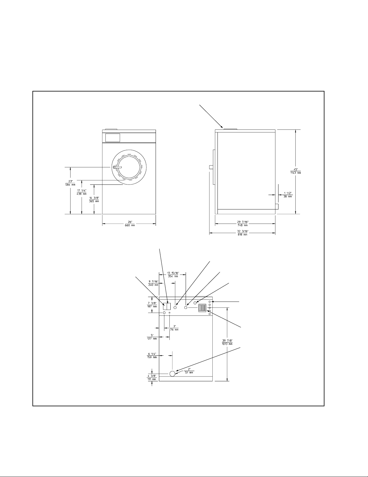
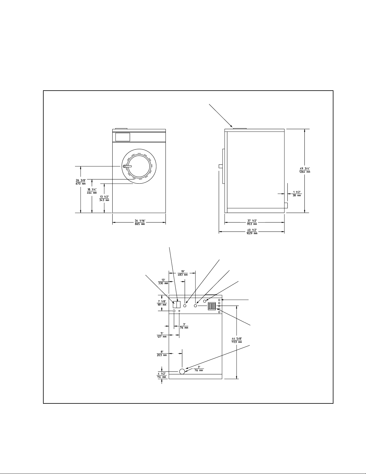
Machine Dimensions
Figures 3 through 8 illustrate the machine
dimensions for each size of machine, starting
with the 18-pound model and finishing with
the 80-pound model.
Note:
purposes only. They are approximate and
subject to normal manufacturing tolerances. If
exact dimensions are required for construction
purposes, contact the distributor or the
manufacturer. We reserve the right to make
changes at any time without notice.
The dimensions shown are for planning
20
F232062
Page 23

Supply Dispenser
Installation
External Chemical Supply Signal
Terminal Strip (OPL only)
Input Power Block
18-Pound Capacity Machines
Cold Water Inlet
Hot Water Inlet
Extra Water Inlet (optional)
External Chemical
Supply Inlets (OPL only)
Vacuum Breaker
Drain Outlet
H001IE3A
Figure 3
F232062
21
Page 24
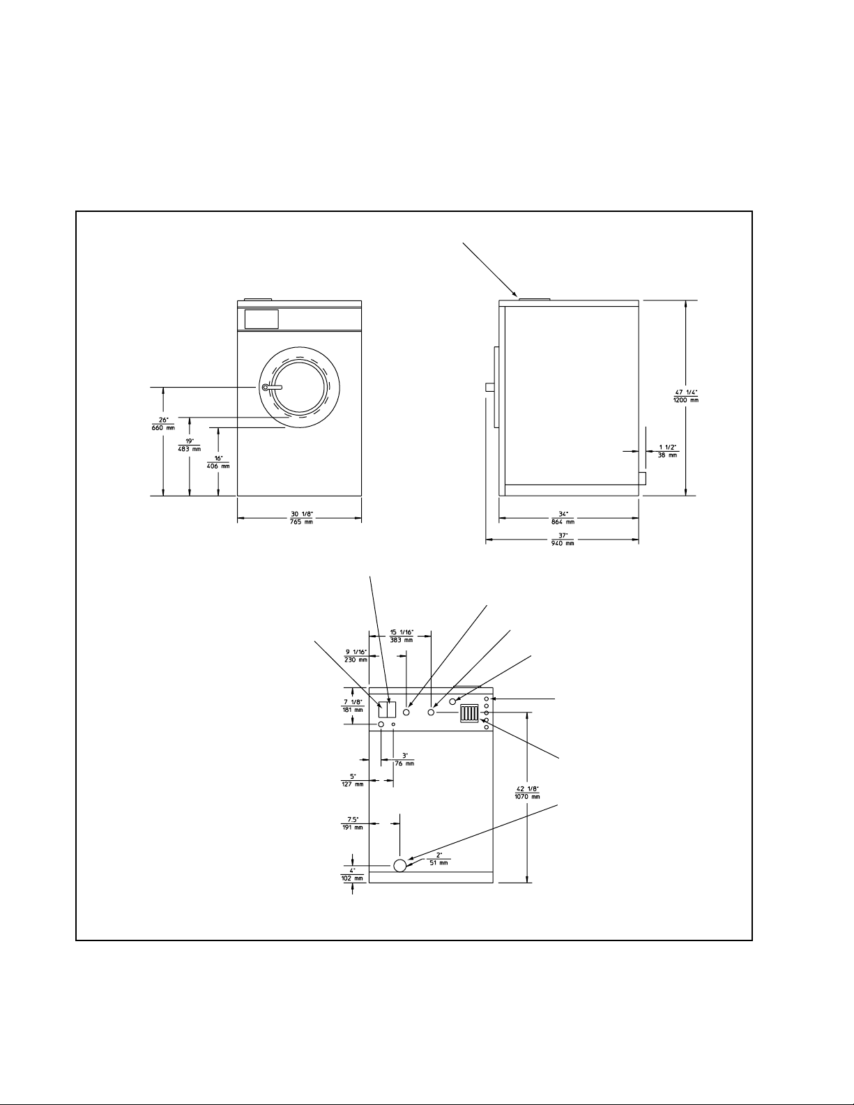
Installation
Machine Dimensions
(Continued)
Supply Dispenser
External Chemical Supply Signal
Terminal Strip (OPL only)
Input Power Block
25-Pound Capacity Machines
Cold Water Inlet
Hot Water Inlet
Extra Water Inlet (optional)
External Chemical
Supply Inlets (OPL only)
Vacuum Breaker
Drain Outlet
H002IE3A
Figure 4
22
F232062
Page 25

Supply Dispenser
Installation
External Chemical Supply Signal
Terminal Strip (OPL only)
Input Power Block
27-Pound Capacity Machines
Cold Water Inlet
Hot Water Inlet
Extra Water Inlet (optional)
External Chemical
Supply Inlets (OPL only)
Vacuum Breaker
Drain Outlet
H003IE3A
Figure 5
F232062
23
Page 26
Installation
Machine Dimensions
(Continued)
Supply Dispenser
External Chemical Supply Signal
Terminal Strip (OPL only)
Input Power Block
35-Pound Capacity Machines
Cold Water Inlet
Hot Water Inlet
Extra Water Inlet (optional)
External Chemical
Supply Inlets (OPL only)
Vacuum Breaker
Drain Outlet
H004IE3A
Figure 6
24
F232062
Page 27
Supply Dispenser
Installation
External Chemical Supply Signal
OPL only
Terminal Strip (OPL only)
Input Power Block
50-Pound Capacity Machines
Cold Water Inlet
Hot Water Inlet
Extra Water Inlet (optional)
External Chemical
Supply Inlets (OPL only)
Vacuum Breaker
Drain Outlet
H005IE3A
Figure 7
F232062
25
Page 28
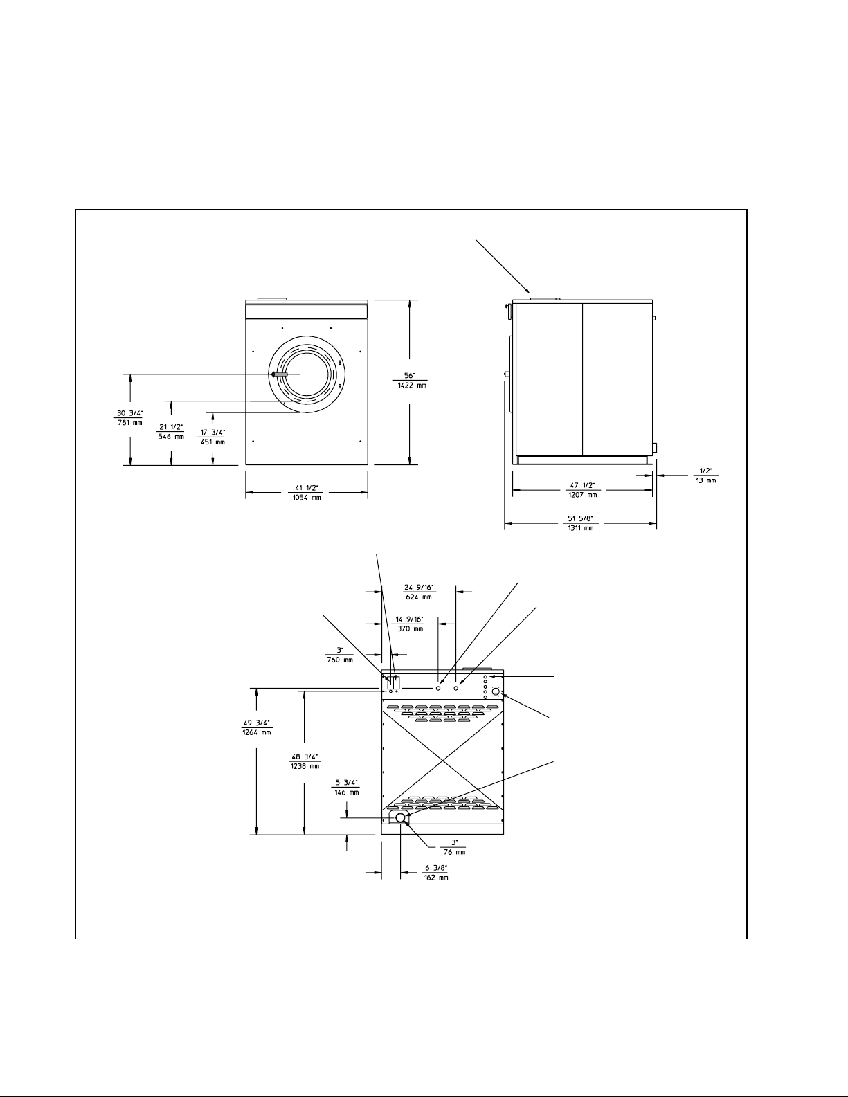
Installation
Machine Dimensions
External Chemical Supply Signal
Terminal Strip (OPL only)
(Continued)
Supply Dispenser
Cold Water Inlet
Input Power Block
80-Pound Capacity Machines
Hot Water Inlet
External Chemical
Supply Inlets (OPL only)
Vacuum Breaker
Drain Outlet
H049IE3A
Figure 8
26
F232062
Page 29
Installation
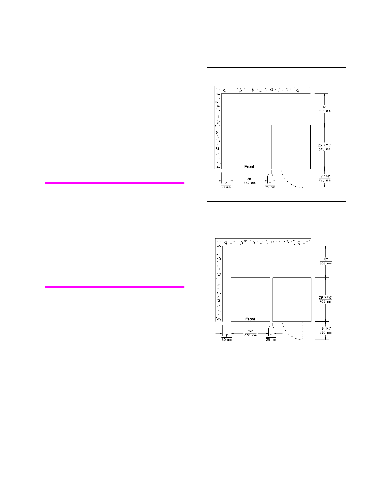
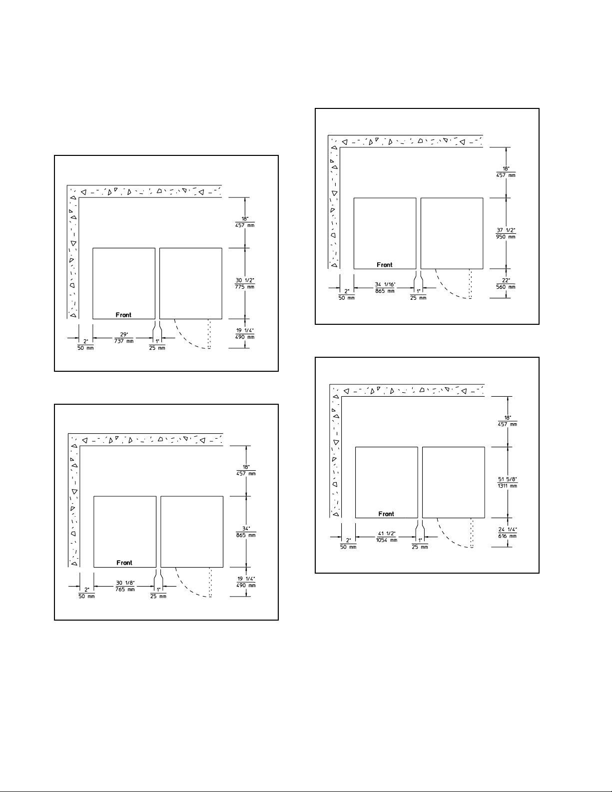
Dimensional Clearances
Allow a minimum of 12 inches (305 mm) at
the rear for 18-pound and 25-pound capacity
models and a minimum of 18 inches (457 mm)
at the rear for the larger machines. Allow
2 inches (51mm) at the sides and 1 inch
(25 mm) between machines in multiple
installations. Dimensional clearances are
indicated in Figures 9 through 14 for each size
of machine, starting with the 18-pound model
and finishing with the 80-pound model.
Note:
80-pound model are dependent upon which set
of mounting bolt holes is used. If the machine
is intended for close mounting (mounting bolt
pattern labeled "A" in Figure 28), follow the
clearances in Figure 14. If the machine is
intended for standard mounting (mounting bolt
pattern labeled "B" in Figure 28), provide a
minimum clearance of 8 inches (203 mm) at
each side of the machine in addition to the
clearances in Figure 14.
The dimensional clearances for the
18-Pound Capacity Machines
H019IE1A
Figure 9
25-Pound Capacity Machines
F232062
H020IE1A
Figure 10
27
Page 30
Installation
Dimensional Clearances
(Continued)
27-Pound Capacity Machines
Figure 11
50-Pound Capacity Machines
H023IE1A
Figure 13
H021IE1A
80-Pound Capacity Machines
35-Pound Capacity Machines
Figure 12
H048IE1A
Figure 14
H022IE1A
28
F232062
Page 31

Installation
Machine Foundation
Note:
above ground level, or over basements or
crawlspaces. Installation must be “slab on
grade” or equivalent.
Do not mount on wooden floors,
CAUTION
Ensure that the machine is installed on a
level floor of sufficient strength and that the
recommended clearances for inspection
and maintenance are provided. Never allow
the inspection and maintenance space to
be blocked.
A proper foundation is absolutely necessary
for all models because of the high extract
speed and the G-forces exerted.
SW020
The machine must be anchored to a smooth
level surface so that the entire base of the
machine is supported and rests on the
mounting surface. (Do not support the machine
on only four points.) Anchor bolts for machine
sizes up to the 50-pound capacity model must
be a minimum of 5/8-inch diameter, grade 2.
Anchor bolts for the 80-pound capacity model
must be a minimum of 3/4-inch diameter,
grade 2.
Care must be exercised in the design of the
mounting base due to the force exerted by the
machine during extract.
Static and dynamic loads on the floor or
foundation are shown in the Cabinet
Hardmount Floor Load Data tables in this
subsection. These tables can be used as a
reference when designing floors and
foundations.
Thoroughness of detail must be stressed with
all foundation work to insure a stable unit
installation, eliminating possibilities of
excessive vibration during extract.
The machine must be secured to a foundation
or floor of adequate construction. The floor
must be 3500 psi minimum reinforced
concrete embedded in clean, compacted fill
dirt. For 2-speed models, the floor must be at
least 4 inches (102 mm) thick. For 3-speed
and variable-speed models (except for the
80-pound capacity model), the floor must be at
least 6 inches (152 mm) thick. For 80-pound
capacity models, the floor must be at least 9
inches (229 mm) thick.
F232062
29
Page 32

Installation
Machine Foundation
(Continued)
Cabinet Hardmount Floor Load Data, 2-Speed Models
Specification 18 25 27 35 50
Static floor load, lbs (kN) 476 (2.12) 549 (2.44) 653 (2.90) 804 (3.58) 1041
(4.63)
Static pressure, lbs-ft2 (kN-m2)
Maximum dynamic load, lbs (kN) 296 (1.31) 420 (1.87) 427 (1.90) 581 (2.58) 860 (3.83)
Dynamic pressure, lbs-ft
Dynamic load frequency, Hz 8.75 9.00 8.00 7.83 7.50
Max. moment about machine base, lbs-ft (kN-m) 567
2
(kN-m2)
104 (4.96) 103 (4.94) 106 (5.07) 113 (5.41) 117 (5.62)
64.4 (3.08) 79.3 (3.80) 69.5 (3.33) 82 (3.91) 97 ( 4.64)
(0.769)
806 (1.12) 854 (1.16) 1261
(1.71)
1892
(2.57)
Cabinet Hardmount Floor Load Data, 3-Speed Models
Specification 18 35 50 80
Static floor load, lbs (kN) 486 (2.16) 829 (3.69) 1171 (5.21) 2047 ( 9.10)
2
Static pressure, lbs-ft
Maximum dynamic load, lbs (kN) 468 (2.08) 910 (4.05) 1340 (5.96) 2288 (10.2)
Dynamic pressure, lbs-ft
Dynamic load frequency, Hz 11.0 9.85 9.35 8.88
Max. moment about machine base, lbs-ft (kN-m) 899 (1.22) 1975 (2.68) 2948 (4.00) 5873 (7.98)
(kN-m2)
2
(kN-m2)
106 (5.07) 117 (5.58) 132 (6.32) 150 (7.18)
102 (4.88) 128 (6.13) 151 (7.23) 167 (8.03)
Cabinet Hardmount Floor Load Data, Variable-Speed Models
Specification 18 27 35 50 80
Static floor load, lbs (kN) 490 (2.18) 677 (3.01) 794 (3.53) 1009
(4.48)
Static pressure, lbs-ft2 (kN-m2)
Maximum dynamic load, lbs (kN) 512 (2.27) 755 (3.36) 979 (4.35) 1407
Dynamic pressure, lbs-ft
Dynamic load frequency, Hz 11.52 10.68 10.22 9.58 8.67
Max. moment about machine base, lbs-ft (kN-m) 983 (1.33) 1450
2
(kN-m2)
107 (5.11) 110 (5.26) 112 (5.35) 114 (5.46) 135 (6.46)
(6.25)
112 (5.35) 123 (5.88) 138 (6.60) 159 (7.61) 161 (7.71)
(1.97)
2125
(2.88)
3095
(4.19)
1853
(8.23)
2209
(9.80)
5678
(7.68)
30
F232062
Page 33

Mechanical Installation
H025I
H027I
This subsection provides four specific methods
of mechanical installation. Follow the
procedure most appropriate for your machine.
Installation
Note:
Improper installation may void the
warranty. Consult the manufacturer or your
distributor before deviating from the
appropriate procedure.
Expansion Bolt Installation
(2-Speed Models Only)
Note:
Expansion bolts are not suitable
for 3-speed or variable-speed machine
installations. Expansion bolts should not be
used in single-machine concrete foundation
pad installations.
Use the following instructions and Figures
15 through 20 as a step-by-step guide
to installation of the expansion bolts.
1. Verify that the floor is 3500 psi minimum
reinforced concrete embedded in clean,
compacted fill dirt and at least 4 inches
(102 mm) thick.
Figure 15
4. Set the drill depth gauge to 2-9/16 inches
(65 mm). See Figure 16.
H026I
Figure 16
5. Drill the holes to the set depth. See
Figure 17.
2. Verify that the mounting surface is level
and even. If the mounting surface fails to
meet these requirements, the machine
must be installed using J-bolts and
machinery grout.
3. Use the base of the machine as a template
by positioning the machine in the desired
location and marking the pre-drilled
mounting holes on the floor. See
Figure 15.
F232062
Figure 17
31
Page 34

Installation
Mechanical Installation
(Continued)
6. Use compressed air or a squeeze bulb to
clean out each hole. See Figure 18.
Figure 18
7. Install the machine anchors, using the
included tool.
8. Secure the machine to the floor, using the
bolts furnished with the anchors. Tighten
the locknuts by even increments—one
after the other—until all are tightened
evenly and the machine is fastened
securely to the floor. See Figure 19.
H028I
5/8 in. (19 mm)
diameter
Expansion
Bolt
H030IE1A
Locknut
Washer
Note:
Machine
Base
Figure 20
Check and retighten the locknuts after
five to ten days of operation and every three
months thereafter.
H029I
Figure 19
The completed expansion bolt installation is
shown in Figure 20.
32
F232062
Page 35

Installation
H025I
Elevated Base Frame Installation
(2-Speed Models Only)
Note:
The 3-speed and variable-speed
models should not be installed on elevated
base frames.
Factory-built elevated steel base frames are
designed to meet the specifications of the
2-speed model washer-extractor. See
Figure 21.
1. Verify that the floor is 3500 psi minimum
reinforced concrete embedded in clean,
compacted fill dirt. The floor must be at
least 4 inches (102 mm) thick.
2. Use the elevated base frame as a template
by positioning the frame in the desired
location and marking the pre-drilled
mounting holes on the floor. See
Figure 22.
H035I
Figure 21
Use the following instructions and Figures
22 through 26 as a step-by-step guide to
installation of the elevated base frame.
Figure 22
3. Adjust the drill depth gauge to match the
length of the J-bolt, minus 1-1/2 inches
(38 mm). See Figure 23.
H026I
Figure 23
F232062
33
Page 36

Installation
Mechanical Installation
(Continued)
4. Drill and chisel out a conical hole large
enough to accept the J-bolt. See
Figure 24.
Figure 24
5. Use compressed air or a squeeze bulb to
remove debris from each hole. Anchor
J-bolt in place, using an industry-accepted
anchoring compound. Verify that the
J-bolts are in the correct locations and that
1-1/2 inches (38 mm) of each J-bolt
protrude from the floor. See Figure 25.
H031I
7. Fill the space between the frame base
and the floor with a good quality
non-shrinking machinery grout to ensure a
stable installation. Grout completely under
all frame members.
8. Remove the spacers carefully, allowing the
base frame to settle into the wet grout.
9. Before grout sets completely, make a drain
opening in the rear of the base frame
grouting with a stiff piece of wire. This
opening should be approximately 1/2 inch
(13 mm) wide to allow any surface water
build-up under the base of the machine to
drain away.
Do not omit this step.
10. Position washers and locknuts on J-bolts
and fingertighten nuts to machine base.
11. After the grout is completely dry, tighten
locknuts by even increments—one after
the other—until all are tightened evenly
and the base frame is fastened securely to
the floor. See Figure 26.
Figure 25
6. Raise and level the base frame 1/2 inch
(13 mm) off the floor on three points,
using spacers such as nut fasteners.
34
H032IE1A
H033I
Figure 26
12. Position the machine over the base frame,
aligning the mounting holes on the
machine with the corresponding holes on
the frame.
F232062
Page 37

Installation
13. Install a bolt, lockwasher, and nut in each
mounting hole. Use 5/8" – 18 x 2 grade 5
mounting bolts with 5/8" – 18 grade B nuts
and 5/8" lockwashers.
14. Handtighten each nut.
15. Tighten the two rear nuts two turns.
16. Tighten the two front nuts two turns.
17. On 25-pound, 27-pound, 35-pound, and
50-pound capacity models, tighten the two
middle nuts firmly.
18. Tighten the two front nuts firmly; tighten
the two rear nuts firmly.
Note:
five to ten days of operation and every three
months thereafter.
Check and retighten the locknuts after
J-Bolt Installation
Install J-bolts in concrete per the mounting
bolt layouts in Figures 27 and 28. Use the
following instructions and Figures 29 through
33 as a guide to step-by-step installation of the
J-bolts.
1. Verify that the floor is 3500 psi minimum
reinforced concrete embedded in clean,
compacted fill dirt. For 2-speed models,
the floor must be at least 4 inches
(102 mm) thick. For 3-speed and variablespeed models (except for the 80-pound
capacity model), the floor must be at least
6 inches (152 mm) thick. For 80-pound
capacity models, the floor must be at least
9 inches (229 mm) thick.
F232062
35
Page 38

Installation
Mechanical Installation
18-Pound Capacity Machines 25-Pound Capacity Machines
(Continued)
36
27-Pound Capacity Machines 35-Pound Capacity Machines
50-Pound Capacity Machines
Figure 27
H024IE3A
F232062
Page 39

Installation
80-Pound Capacity Machines
Note:
There are two different mounting bolt
layouts which may be used for the 80-pound
capacity machine. See Figure 28. The bolt
holes marked A are to be used for close
mounting—machines installed with a 1-inch
(25.4 mm) clearance between machines.
The bolt holes marked B are to be used for
standard mounting—machines installed with
a minimum clearance of 8 inches (203 mm)
between machines.
2. Adjust the drill depth gauge to match the
length of the J-bolt, minus 1-1/2 inches
(38 mm). See Figure 29.
MI003FE1A
Figure 28
H026I
Figure 29
F232062
37
Page 40

Installation
Mechanical Installation
(Continued)
3. Drill and chisel out a conical hole large
enough to accept the J-bolt. See
Figure 30.
Figure 30
4. Use compressed air or a squeeze bulb to
remove debris from each hole. Anchor
J-bolt in place, using an industry-accepted
anchoring compound. Verify that the
J-bolts are in the correct locations and that
1-1/2 inches (38 mm) of each J-bolt
protrude from the floor. See Figure 31.
H031I
6. If the machine is a
2-speed
model and
the mounting surface is level and even,
grouting is optional.
If grouting is not desired, position washers
and locknuts on J-bolts and tighten the
locknuts by even increments—one after
the other—until all are tightened evenly
and the machine is fastened securely to the
floor. See Figure 26.
If grouting is desired (or required by the
condition of the mounting surface),
proceed to step 7.
If the machine is a
speed
model, the machine must be
3-speed
variable-
or
grouted. Proceed to step 7.
7. Raise and level the machine 1/2 inch off
the floor on three points, using spacers
such as nut fasteners.
8. Fill the space between the machine base
and the floor with a good quality
non-shrinking machinery grout to ensure a
stable installation. Grout completely under
all frame members.
Figure 31
5. Place the machine carefully over the
J-bolts. Never attempt to lift the machine
by the door handle or by pushing on the
cover panels.
38
H032IE1A
9. Remove the spacers carefully, allowing the
machine to settle into the wet grout.
10. Before grout sets completely, make a drain
opening in the rear of the machine
grouting with a stiff piece of wire. This
opening should be approximately 1/2 inch
(13 mm) wide to allow any surface water
build-up under the base of the machine to
drain away.
Do not omit this step.
11. Position washers and locknuts on J-bolts
and fingertighten nuts to machine base.
12. After the grout is completely dry, tighten
the locknuts by even increments—one
after the other—until all are tightened
evenly and the machine is fastened
securely to the floor. See Figure 32.
F232062
Page 41

Installation
Concrete Foundation Pad
A concrete foundation pad may be constructed
to elevate the machines. See Figure 34 for a
typical concrete foundation pad installation.
H033I
Figure 32
Note:
Check and retighten the locknuts after
five to ten days of operation and every three
months thereafter.
Figure 33 shows the completed J-bolt
installation with grout.
Locknut
Machine
Base
1/2 in. (13 mm)
Machinery
Grout
J-Bolt
Note:
Expansion bolts should not be used
in single-machine concrete foundation
pad installations.
1. Verify that the floor is 3500 psi minimum
reinforced concrete embedded in clean,
compacted fill dirt. For 2-speed models,
the floor must be at least 4 inches
(102 mm) thick. For 3-speed and variablespeed models (except for the 80-pound
capacity model), the floor must be at least
6 inches (152 mm) thick. For 80-pound
capacity models, the floor must be at least
9 inches (229 mm) thick.
2. Break up and excavate the floor to a depth
of approximately 9 inches (230 mm)
below the floor surface, making certain
that the sides of the hole slope outwards
from top to bottom.The bottom of the hole
should be 5 inches (127 mm) larger all
around than the top.
F232062
Figure 33
H034IE1A
Note that when installation is complete,
the top of the pad should extend a
minimum of 4 inches (102 mm) out from
the machine on all sides.
3. Wet the hole well and brush the bottom
and sides with cement grout.
39
Page 42

Installation
Mechanical Installation
Pad height
must not exceed
8 in. (203 mm).
(Continued)
1 in. (25 mm) minimum
4 in. (102 mm)
minimum
4. Use rebar or other appropriate material to
ensure that the concrete foundation pad
will be sufficiently connected to the
existing floor.
5. Prepare a form for the above-ground
portion of the pad and fill form and
excavation with concrete to join the
foundation. Verify that top of pad is level.
The height of the pad must not exceed
8 inches (203 mm).
6. Use the mounting bolt layout in Figures
27 and 28 to properly position the
mounting bolts in the wet concrete.
When using J-bolts, allow 1-1/2 inches
(38 mm) to extend above the surface of
the concrete.
7. Allow concrete to dry.
Figure 34
H036IE3A
8. Place the machine carefully over the
mounting bolts. Never attempt to lift the
machine by the door handle or by pushing
on the cover panels.
9. If the machine is a
2-speed
model,
grouting is optional.
If grouting is not desired, position washers
and locknuts on J-bolts and tighten the
locknuts by even increments—one after
the other—until all are tightened evenly
and the machine is fastened securely to the
floor. See Figure 35.
If grouting is desired, proceed to step 10.
If the machine is a
speed
machine installed on a concrete
3-speed
variable-
or
foundation pad, the machine must be
grouted. Proceed to step 10.
40
F232062
Page 43

10. Raise and level the machine 1/2 inch off
the pad on three points, using spacers such
as nut fasteners.
11. Fill the space between the machine base
and the pad with a good quality
non-shrinking machinery grout to ensure a
stable installation. Grout completely under
all frame members.
12. Remove the spacers carefully, allowing the
machine to settle into the wet grout.
13. Before grout sets completely, make a drain
opening in the rear of the machine
grouting with a stiff piece of wire. This
opening should be approximately 1/2 inch
(13 mm) wide to allow any surface water
build-up under the base of the machine to
drain away.
Do not omit this step.
Installation
Note:
five to ten days of operation and every three
months thereafter.
Check and retighten the locknuts after
14. Position washers and locknuts on J-bolts
and fingertighten nuts to machine base.
15. After the grout is completely dry, tighten
the locknuts by even increments—one
after the other—until all are tightened
evenly and the machine is fastened
securely to the concrete foundation pad.
See Figure 35.
H033I
Figure 35
F232062
41
Page 44

Installation
Drain Connection
A drain system of adequate capacity is
essential to machine performance. Ideally, the
water should empty through a vented pipe
directly into a sump or floor drain. Figures
36 and 37 show typical drain line and drain
trough configurations.
Drain Valve
Drain Hose
A flexible connection must be made to a
vented drain system to prevent an air lock and
to prevent siphoning. If proper drain size is not
available or practical, a surge tank is required.
A surge tank in conjunction with a sump pump
should be used when gravity drainage is not
possible, such as in below-ground-level
installations.
Overflow
Hose
Drain Tee
Floor
Open Drain Trough
Drain Valve
Drain Hose
H050IE3A
Figure 36
Vent Pipe
Overflow
Hose
Drain Tee
H051IE3A
Figure 37
42
F232062
Page 45

Installation
Before any deviation from specified
installation procedures is attempted,
the customer or installer should contact
See the Cabinet Hardmount Drain Information
table in this subsection for capacity-specific
drain information.
the distributor.
Installation of additional machines will require
Increasing the drain hose length, installing
elbows, or causing bends will decrease drain
flow rates and increase drain times, impairing
proportionately larger drain connections. See
the Cabinet Hardmount Drain Line Sizing
table in this subsection.
machine performance.
Cabinet Hardmount
Drain Information
18 25 27 35 50 80
Drain connection size, ID, in (mm) 2 (52) 2 (52) 2 (52) 2 (52) 3 (76) 3 (76)
Number of drain outlets 111111
Drain flow capacity, gal-min (l-min) 20 (76) 25 (95) 25 (95) 35 (132) 50 (189) 50 (189)
Recommended drain pit size, ft
3
(l)
1.80 (51) 2.36 (66.8) 2.50 (70.3) 3.14 (88.9) 4.52 (128) 5.90 (169)
Cabinet Hardmount
Drain Line Sizing
Minimum Drain I.D. [in (mm)]
Number Of Machines
Model
12345
18 2 (51) 3 (76) 3 (76) 4 (102) 4 (102)
25 2 (51) 3 (76) 3 (76) 4 (102) 4 (102)
27 2 (51) 3 (76) 3 (76) 4 (102) 4 (102)
35 3 (76) 3 (76) 3-1/2 (89) 4 (102) 4 (102)
50 3 (76) 4 (102) 6 (152) 6 (152) 6 (152)
80 4 (102) 6 (152) 6 (152) 8 (203) 8 ( 203)
F232062
43
Page 46

Installation
Water Connection
Cabinet Hardmount
Water Supply Information
Water inlet connection size, in (mm) 3/4 (19)
Number of water inlets (standard) 2
Recommended pressure, psi (bar) 30 – 85 (2 – 5.7)
Inlet flow capacity, gal-min/l-min (80psi) 12 (45)
Connections should be supplied by a hot and
a cold water line of at least the sizes shown
in the Water Supply Line Sizing table.
Installation of additional machines will require
proportionately larger water lines. See table.
To connect water service to machine with
rubber hoses, use the following procedure:
1. Before installing hoses, flush the water
system for at least 2 minutes.
2. Check filters in the machine’s inlet hoses
for proper fit and cleanliness before
connecting.
Cabinet Hardmount
Water Supply Line Sizing
Capacity
18 – 50
80
Number
Of
Machines
1 3/4 (19) 3/4 (19)
2 1 (25) 3/4 (19)
3 1-1/4 (32) 1 (25)
4 1-1/2 (38) 1 (25)
1 1 (25) 3/4 (19)
2 1-1/2 (38) 1 (25)
3 2 (50) 1-1/4 (32)
4 2 (50) 1-1/2 (38)
Supply Line Size
[in (mm)]
Main Hot/cold
Suitable air cushions should be installed in
supply lines to prevent “hammering.” See
Figure 38. If the water pressure is above
60 psi, flexible copper tubing should be used in
place of rubber hoses.
3. Hang hoses in a large loop; do not allow
them to kink.
If additional hose lengths are needed, use
flexible hoses with screen filters. Each hose
should have a screen filter installed to keep
rust and other foreign particles out of the water
inlet valves.
Pressure of 30 – 85 psi (2 – 5.7 bar) provides
best performance. Although the machine will
function properly at lower pressure, increased
fill times will occur.
44
Air Cushions
(Risers)
Water Supply
Faucets
MW008JE1A
Figure 38
F232062
Page 47

Installation
Never touch terminals or components of
the AC inverter drive unless power is
disconnected and the “CHARGE” indicator
LED is off. The AC inverter drive retains
potentially deadly voltage for some time
after the power is disconnected. There are
no user-serviceable parts inside the
AC inverter drive. Tampering with the drive
will void the warranty.
SW009
WARNING
When controlling the AC inverter drive with
a parameter unit, the machine’s computer
and its safety features are bypassed. This
would allow the basket to rotate at high
speeds with the door open. When using a
parameter unit to control the AC inverter
drive, a large sign should be placed on the
front of the machine warning people of the
imminent danger.
SW003
DANGER
Electrical Installation
WARNING
This machine must be installed, adjusted,
and serviced by qualified electrical
maintenance personnel familiar with the
construction and operation of this type of
machinery. They must also be familiar with
the potential hazards involved. Failure to
observe this warning may result in personal
injury and/or equipment damage, and may
void the warranty.
SW004
WARNING
Dangerous voltages are present in the
electrical control box(es) and at the motor
terminals. Only qualified personnel familiar
with electrical test procedures, test
equipment, and safety precautions should
attempt adjustments and troubleshooting.
Disconnect power from the machine before
removing the control box cover, and before
attempting any service procedures.
SW005
Machines equipped with an AC inverter drive
require a clean power supply free from voltage
spikes and surges. A voltage monitor should be
used to check incoming power. The customer’s
local power company may provide such a
monitor.
If input voltage measures above 230V for a
200V drive or above 440V for a 400V drive,
ask the power company to lower the voltage.
As an alternative, a step-down transformer kit
is available from the distributor. Voltages
above 250V and 490V require additional
measures. Contact the distributor or the
manufacturer for assistance.
WARNING
Ensure that a ground wire from a proven
earth ground is connected to the ground lug
near the input power block on this machine.
Without proper grounding, personal injury
from electric shock could occur and machine
malfunctions may be evident.
F232062
SW008
45
Page 48

Installation
Electrical Installation
The 2-speed and 3-speed machines have a
thermal overload protector in the drive motor
windings and a separate fuse for the control
circuit. Single-phase machines require a
single-phase inverse-time circuit breaker.
Three-phase machines require a three-phase
inverse-time circuit breaker.
On variable-speed machines, the AC drive
provides thermal overload protection for the
drive motor. However, a separate three-phase
inverse-time circuit breaker must be installed
for complete electrical overload protection.
This prevents damage to the motor by
disconnecting all legs if one should be lost
accidentally. Check the data plate on the back
of the washer-extractor or consult the
Electrical Specifications chart in this
subsection for model-specific circuit breaker
requirements.
(Continued)
Use wire sizes indicated in the Electrical
Specifications chart for runs up to 50 feet. Use
next larger size for runs of 50 to 100 feet. Use
two sizes larger for runs greater than 100 feet.
For personal safety and proper operation, the
machine must be grounded in accordance with
state and local codes. If such codes are not
available, grounding must conform with the
National Electric Code, article 250-95. The
ground connection must be made to a proven
earth ground, not to conduit or water pipes.
Do not connect the ground to the neutral
(N-white wire) leg at the terminal strip.
If three-phase service is unavailable for a
2-speed or 3-speed model and a Roto-Phase or
other phase adder is used, the artificial leg
must be connected to L3 in the input power
junction box.
Note:
breaker.
The machine should be connected to an
individual branch circuit not shared with
lighting or other equipment.
The connection should be shielded in a liquidtight or approved flexible conduit with proper
conductors of correct size installed in
accordance with the National Electric Code or
other applicable codes. The connection must
be made by a qualified electrician using the
wiring diagram provided with the machine, or
according to accepted European standards for
CE approved equipment.
Do NOT use fuses in place of a circuit
CAUTION
Do not use a phase adder on any variablespeed machine.
SW037
If the machine is intended for four-wire
service, a neutral leg must be provided by the
power company.
If a delta supply system is used on a four-wire
model, the high leg must be connected to L3.
Improper connections will result in equipment
damage and will void the warranty.
46
F232062
Page 49

Installation
Cabinet Hardmount
Electrical Specifications
18-Pound Capacity Models
Voltage Designation Standard Electric Heat
Code
Full Load
Voltag e
Cycle
Phase
Wire
Amps
Breaker
Circuit
AWG
mm
Full Load
Breaker
Amps
Circuit
AWG
mm
2
2
2-Speed Models
B 110-120 60 1 2 15 20 12 4.00 N/A
C380-41550344 15142.501415142.50
D220-24050335 15142.502425106.00
E 220-240 50 1 2 10 20 12 4.00 42 45 6 16.0
F440-48060334 15142.501620124.00
O208-24060335 15142.502425106.00
U
Y 208-240 60 1 2 10 20 12 4.00 N/A
380 50344 15142.501415142.50
240 50335 15142.502425106.00
3-Speed Models
A208-24060347 15142.502430106.00
C380-41550345 15142.501520124.00
D220-24050337 15142.502430106.00
F440-48060335 15142.501520124.00
O208-24060337 15142.502430106.00
Variable-Speed Models
O 208-240 60 3 3 3.84 15 14 2.50 N/A
Y 208-240 60 1 2 3.84 15 14 2.50 N/A
Wire sizes shown are for copper, THHN, 90° conductor per NEC article 310.
Note:
F232062
47
Page 50

Installation
y)
Electrical Installation
(Continued)
Cabinet Hardmount
Electrical Specifications
25-Pound and 27-Pound Capacity Models
Voltage Designation Standard Electric Heat
Code
Full Load
Voltag e
Cycle
Phase
Wire
Amps
Breaker
Circuit
AWG
mm
2
Full Load
Breaker
Amps
Circuit
AWG
mm
2
2-Speed Models
C380-41550344 15142.501515142.50
D220-24050336 15142.502425106.00
E 220-240 50 1 2 10 20 12 4.00 42 45 6 16.0
F440-48060334 15142.501620124.00
O208-24060337 15142.502525106.00
U
380 50344 15142.501515142.50
240 50336 15142.502425106.00
Y 208-240 60 1 2 10.5 20 12 4.00 N/A
Variable-Speed Models (27-pound capacity models onl
O 208-240 60 3 3 4.8 15 14 2.50 N/A
Y 208-240 60 1 2 4.8 15 14 2.50 N/A
Wire sizes shown are for copper, THHN, 90° conductor per NEC article 310.
Note:
48
F232062
Page 51

Installation
Cabinet Hardmount
Electrical Specifications
35-Pound Capacity Models
Voltage Designation Standard Electric Heat
Code
Full Load
Voltag e
Cycle
Phase
Wire
Amps
Breaker
Circuit
AWG
mm
Full Load
Breaker
Amps
Circuit
AWG
mm
2
2
2-Speed Models
C380-41550345 15142.502630106.00
D 220-240 50 3 3 7 20 12 4.00 43 50 6 16.0
E 220-240 50 1 2 12 25 10 6.00 N/A
F440-48060335 15142.502630106.00
O 208-240 60 3 3 7 20 12 4.00 43 50 6 16.0
U
Y 208-240 60 1 2 12 25 10 6.00 N/A
380 50345 15142.502630106.00
240 50 3 3 7 20 12 4.00 43 50 6 16.0
3-Speed Models
A 208-240 60 3 4 12 30 10 6.00 44 50 6 16.0
C380-41550346 20124.002830106.00
D 220-240 50 3 3 10 30 10 6.00 44 50 6 16.0
F440-48060336 20124.002830106.00
O 208-240 60 3 3 12 30 10 6.00 44 50 6 16.0
Variable-Speed Models
O 208-240 60 3 3 5.86 15 14 2.50 N/A
Y 208-240 60 1 2 5.86 15 14 2.50 N/A
Wire sizes shown are for copper, THHN, 90° conductor per NEC article 310.
Note:
F232062
49
Page 52

Installation
Electrical Installation
(Continued)
Cabinet Hardmount
Electrical Specifications
50-Pound Capacity Models
Voltage Designation Standard Electric Heat
Code
Full Load
Voltag e
Cycle
Phase
Wire
Amps
Breaker
Circuit
AWG
mm
2
Full Load
Breaker
Amps
Circuit
AWG
2-Speed Models
C 380-415 50 3 4 6 15 14 2.50 39 50 6 16.0
D 220-240 50 3 3 10 20 12 4.00 64 70 4 25.0
E 220-240 50 1 2 15 30 10 6.00 N/A
F 440-480 60 3 3 6 15 14 2.50 39 50 6 16.0
O 208-240 60 3 3 10 20 12 4.00 64 70 4 25.0
Y 208-240 60 1 2 15 30 10 6.00 10 20 12 4.00
mm
2
3-Speed Models
A 208-240 60 3 4 13 30 10 6.00 64 70 4 25.0
C 380-415 50 3 4 7 20 12 4.00 39 50 6 16.0
D 220-240 50 3 3 13 30 10 6.00 62 70 4 25.0
F 440-480 60 3 3 7 20 12 4.00 39 50 6 16.0
O 208-240 60 3 3 13 30 10 6.00 64 70 4 25.0
Variable-Speed Models
O 208-240 60 3 3 10.9 15 14 2.50 66.5 70 4 2.50
Y 208-240 60 1 2 10.9 15 14 2.50 N/A
Wire sizes shown are for copper, THHN, 90° conductor per NEC article 310.
Note:
50
F232062
Page 53

Installation
Cabinet Hardmount
Electrical Specifications
80-Pound Capacity Models
Voltage Designation Standard Electric Heat
Code
Full Load
Voltag e
Cycle
Phase
Wire
Amps
Breaker
Circuit
AWG
mm
Full Load
Breaker
Amps
Circuit
AWG
mm
2
3-Speed Models
A 208-240 60 3 4 15 40 6 16 90 100 1 45
C 380-415 50 3 4 9 20 12 4 41 45 6 16
D 220-240 50 3 3 14 40 6 16 89 90 2 35
F 440-480 60 3 3 9 20 12 4 46 50 6 16
O 208-240 60 3 3 15 40 6 16 90 100 1 45
W 380-415 50 3 3 9 20 12 4 41 45 6 16
Variable-Speed Models
F 440-480 60 3 3 4.49 15 14 2.50 N/A
O 208-240 60 3 3 12.4 20 12 4 87.46 90 2 35
Wire sizes shown are for copper, THHN, 90° conductor per NEC article 310.
Note:
If the machine fails to operate after power is
connected, disconnect power and check the
control circuit fuse. Unlock and raise the top
cover. For mechanical timer, P-computer, and
S-computer models, the control circuit fuse is
on the center brace. For EDC and V-computer
models, dual control circuit fuses (1 primary
and 1 secondary) are in the control module. A
decal identifies the fuse (or fuses) in each case,
and provides the fuse rating appropriate to that
specific model.
2
If the control circuit fuse has blown, replace
with a fuse of the appropriate rating as
identified by the decal. Call a qualified
electrician if the replacement fuse blows.
F232062
51
Page 54

Installation
Steam Requirements
(Steam Heat Option Only)
WARNING
Never touch internal or external steam
pipes, connections, or components. These
surfaces can be extremely hot and will
cause severe burns. The steam must be
turned off and the pipe, connections, and
components allowed to cool before the pipe
can be touched.
For machines equipped with optional steam
heat, install piping in accordance with
approved commercial steam practices. Steam
requirements are shown in the table below.
SW014
Cabinet Hardmount
Steam Supply Information
Steam inlet connection size, in (mm) 1/2 (13)
Number of steam inlets 1
Recommended pressure, psi (bar) 30-80 (2.0-5.4)
Maximum pressure, psi (bar) 80 (5.4)
Note:
Failure to install the steam filter may
void the warranty.
52
F232062
Page 55

Installation
Chemical Injection Supply
System
Machines intended for use in on-premises
laundries can be attached to an external liquid
chemical injection supply system. See the
Chemical Injection Supply System table in this
subsection for more information.
WARNING
Wear eye and hand protection when
handling chemicals; always avoid direct
contact with raw chemicals. Read the
manufacturer’s directions for accidental
contact before handling chemicals. Ensure
an eye-rinse facility and an emergency
shower are within easy reach. Check at
regular intervals for chemical leaks.
SW016
Cabinet Hardmount
Chemical Injection Supply System
Number of dry supply compartments 3
Number of liquid supply connections 4 or 5*
Liquid supply connection size, in (mm) 5/16 (8)
*Only V-computer models have 5 supply connections.
Undiluted chemical dripping can damage the
machine. Therefore, all chemical injection
supply dispenser pumps should be mounted
below the washer’s injection point. All
dispenser tubing should also run below the
injection point. Loops do not prevent drips
if these instructions are not followed. Failure
to follow these instructions could damage
the machine and void the warranty. Figure
39 shows a typical chemical injection supply
system.
Injection
Point
PVC
Pipe
Chemical Dispenser
Pump Outlet
H038IE3A
Figure 39
F232062
53
Page 56

Installation
Chemical Injection Supply
System
Four hose barbs (five on V-computer models)
on the rear of the machine facilitate connection
to an external chemical injection supply
system. The arrangement of the hose barbs
will form either a straight line or a box. Figure
40 indicates which hose barb corresponds to
which supply.
(Continued)
1
2
3
4
5
1
3
2
4
Machines connected to 400VAC do not
provide L1 and L2 outputs. An external power
source must be provided to power the chemical
supply pump.
Do not use L1 or L2 with the common line to
deliver 120VAC to chemical injection supply
pumps if the machine is equipped with a
control transformer. The transformer will not
be able to provide enough current to operate
the control circuits and drive the chemical
supply pumps.
CAUTION
Attempting to obtain 110VAC by using L1 or
L2 with the common may damage laundry
machine circuitry and/or the chemical
injection system. Using a 240VAC power
wire in the washer-extractor and an earth
ground to obtain 110VAC could cause
microprocessor problems.
SW028
Figure 40
A terminal strip in the input power junction
box provides supply output signals for the
chemical injection supply system.
Note:
Do not attempt to make chemical
injection supply pump electrical connections
to points other than those provided specifically
for that purpose by the factory.
Machines connected to 200VAC provide L1
and L2 fused outputs rated at 3 amps which
may be used to power 208 – 240VAC
supply pumps.
54
Consult the chemical injection supply system
instructions for operational details. See
Figures 41 through 47 for terminal strip decals.
F232062
Page 57

Installation
H054IE1A
380-415 Volt 50 Hz 3 4-Wire Models
H055IE1A
220-240 Volt 50 Hz 1 2-Wire and 3 3-Wire Models
H052IE1A
208-240 Volt 60 Hz 1 3-Wire and 3 4-Wire Models
Figure 41
H053IE1A
120 Volt 60 Hz 1 2-Wire Models
Figure 43
Figure 42
F232062
Figure 44
55
Page 58

Installation
Chemical injection Supply
System
(Continued)
H056IE1A
440-480 Volt 60 Hz 3 3-Wire Models
Figure 45
H057IE1A
208-240 Volt 60 Hz 1 2-Wire and 3 3-Wire Models
H058IE1A
380-415 Volt 50 Hz 3 3-Wire Models
Figure 47
56
Figure 46
F232062
Page 59

Installation
Control Function Test
The machine should be cleaned after
the installation is complete. A function test
should then be executed on the unloaded
machine:
1. Check the power supply for such
characteristics as correct voltage, phase,
and cycles to be certain they are correct for
the machine.
2. Open manual shut-off valves to
the machine.
3. Turn on electric power.
4. Check the door interlock before starting
operation:
a. Open the loading door.
For coin-operated machines, press the
round button on the door handle and
turn the door handle downward.
If the door lock and interlock are
not functioning properly, call a
service technician.
5. Run a complete cycle, checking operation
of water inlet valves, drain, and
extract functions.
6. Cylinder rotation must be
counterclockwise in the extract step. If
rotation is not counterclockwise in the
extract step, disconnect power. For
variable-speed models, have a qualified
electrician reverse any two motor leads
at the AC drive terminal block (terminals
U, V, and W). See Figure 48. For
2-speed and 3-speed models, have a
qualified electrician use the wiring
diagram included with the machine to
determine which input power leads
should be switched.
For machines intended for use in
on-premises laundries, press and hold
the door-unlock button on the left side
of the control panel. Press the round
button on the door handle and turn the
door handle downward.
b. Attempt to start the machine with the
door open. The machine should not
start with the door open.
c. Close the door without locking it and
attempt to start the machine. The
machine should not start with the
door unlocked.
d. Close and lock the door and start a
cycle. Attempt to open the door while
the cycle is in progress. The door
should not open.
F232062
57
Page 60

Installation
Power Supply
Input Power
Block on
Washer-Extractor
AC Drive Connections
Motor Leads
Main Drive Motor
MV001FE1A
Figure 48
58
F232062
Page 61

Section 3
Maintenance
Routine maintenance maximizes operating
efficiency and minimizes downtime. The
maintenance procedures described in this
section will prolong the service life of the
machine and help to prevent accidents.
WARNING
Be careful when handling sheet-metal parts.
Sharp edges can cause personal injury.
Wear safety glasses and gloves, use the
proper tools, and provide adequate lighting.
SW035
CAUTION
Replace all panels that are removed to
perform service and maintenance
procedures. Do not operate the machine
with missing guards or with broken or
missing parts. Do not bypass any
safety devices.
SW019
Daily
Beginning of Day
1. Inspect water inlet valve hose connections
on the back of the machine for leaks.
2. Inspect steam hose connections for leaks
(where applicable).
3. Verify that insulation is intact on all
external wires and that all connections are
secure. If bare wire is evident, call a
service technician.
4. Check door interlock before
starting operation:
a. Attempt to start the washer with the
door open. The washer should not start
with the door open.
b. Close the door without locking it and
attempt to start the washer. The washer
should not start with the door unlocked.
Daily, weekly, monthly, and quarterly
checklists are provided at the end of this
section. Laminate the checklists to preserve
them for repeated copying. Operators and
technicians are encouraged to add checks
specific to their machine’s particular
application. Space is provided on the
checklists for this purpose.
The following maintenance procedures
must be performed regularly at the
required intervals.
F232062
c. Close and lock the door and start a
cycle. Attempt to open the door while
the cycle is in progress. The door
should not open.
If the door lock and interlock are
not functioning properly, call a
service technician.
59
Page 62

Maintenance
Daily
End of Day
Note:
each completed cycle
buildup. Leave loading door open
completed cycle
evaporate.
(Continued)
1. Clean the door gasket of residual detergent
and all foreign matter.
2. Clean automatic supply dispenser lid
and general area. Flush dispenser with
clean water.
3. Clean the washer’s top, front, and side
panels with mild detergent. Rinse with
clean water.
4. Leave loading door open at the end of each
day to allow moisture to evaporate.
Unload the machine promptly
to prevent moisture
to allow moisture to
after
after each
c. Wash the filter with warm water and
allow filter to air-dry. As an alternative,
the filter may be vacuumed clean.
WARNING
The control module cover and fan filter must
be in place for the fan to properly cool the
AC inverter drive. Failure to observe this
warning will void the warranty and could
lead to expensive AC inverter drive repair.
SW038
2. Check the machine for leaks.
a. Start an unloaded cycle to fill
the machine.
b. Verify that door and door gasket do
not leak.
c. Verify that the drain valve is operating
and that the drain system is free
from obstruction. If water does not
leak out during the prewash segment,
the drain valve is closed and
functioning properly.
Weekly
For variable-speed models only,
1.
the AC drive box filter(s) weekly or more
frequently as needed:
Note:
fan filter must be cleaned immediately to
prevent possible damage. Press thermostat
button to reset indicator light.
60
If fan filter service indicator light is on,
a. Open the top cover.
b. Grasp the filter handle and pull straight
up to remove filter.
clean
Monthly
Note:
its source before performing the monthly
maintenance procedures.
Disconnect power to the machine at
For 80-pound capacity models only,
1.
lubricate bearings and seals each month
OR after every 200 hours of operation.
See Figure 49.
a. Use a premium-grade lithium-based #2
grease. Never mix two types of grease,
such as petroleum and silicone.
F232062
Page 63

Maintenance
H040IE1A
Motor
Motor
Pulley
Basket
Pulley
Straight
Edge
b. Pump the grease gun slowly, permitting
only the following number of strokes:
•
Bearing grease fitting, 2 strokes
•
Seal grease fitting, 1 stroke
Seal Grease Fitting
Do not pump the grease gun until
grease comes out of the bearing
housing. This can result in
overlubrication, causing damage
to bearings and seals.
Bearing Grease Fitting
2. Use the following procedures to determine
if V belt(s) require replacement or
adjustment. Call a qualified service
technician in either case.
a. Check V belt(s) for uneven wear and
frayed edges.
b. For groove-pulley drive systems, verify
alignment by placing a straightedge
across both pulley faces. The
straightedge should make contact with
the pulleys in four places. See
Figure 50.
F232062
H047IE3A
Figure 49
Figure 50
61
Page 64

Maintenance
Monthly
(Continued)
c. For flat-pulley drive systems, verify
allowable distance of belt from edge of
pulley as shown in chart below:
Cabinet Hardmount
Flat Pulley Alignment
Allowable
Model
Distance from
Edge (in.)
18 3/32
27 3/32
35 3/32
50 3/8
For 3-speed and variable-speed
d.
models only,
verify that V belts are
properly tensioned by applying a set
force to the belt and measuring the
deflection to determine the belt tension.
See the tables below for the acceptable
belt tension ranges. Belt tension
measurements should be taken as close
to the center of the belt span as
possible. See Figure 51.
Deflection
Span
Length
H039IE1A
Figure 51
3. Remove back panel and check overflow
hose and drain hose for leaks.
4. Unlock the hinged lid and check the
supply dispenser hoses and
hose connections.
62
F232062
Page 65

Maintenance
Cabinet Hardmount Belt Tension Testing for 3-Speed Models
Model
18
35
50
80
Voltag e
Code
C, D Motor-Basket 15.3 (389) 7/32 – 1/4 (5.6 – 6.4) 4.4 – 6.6 (19.6 – 29.4)
A, F, O Motor-Basket 15.6 (396) 7/32 – 1/4 (5.6 – 6.4) 3.5 – 5.5 (15.6 – 24.5)
C, D
A, F, O
C, D
A, F, O
C, D
A, F, O
Belt
Motor-Motor 16.6 (422) 1/4 – 9/32 (6.4 – 7.1) 4.4 – 6.6 (19.6 – 29.4)
Motor-Basket 9.5 (241) 1/8 – 5/32 (3.2 – 4.0) 4.4 – 6.6 (19.6 – 29.4)
Motor-Motor 16.9 (429) 1/4 – 9/32 (6.4 – 7.1) 3.5 – 5.5 (15.6 – 24.5)
Motor-Basket 9.5 (241) 1/8 – 5/32 (3.2 – 4.0) 4.4 – 6.6 (19.6 – 29.4)
Motor-Motor 14.5 (368) 7/32 – 1/4 (5.6 – 6.4) 4.4 – 6.6 (19.6 – 29.4)
Motor-Basket 9.7 (246) 1/8 – 5/32 (3.2 – 4.0) 3.8 – 5.6 (16.9 – 24.9)
Motor-Motor 14.8 (376) 7/32 – 1/4 (5.6 – 6.4) 3.5 – 5.5 (15.6 – 24.5)
Motor-Basket 9.7 (246) 1/8 – 5/32 (3.2 – 4.0) 3.8 – 5.6 (16.9 – 24.9)
Motor-Motor 15.9 (404) 7/32 – 1/4 (5.6 – 6.4) 7.1 – 9.1 (31.6 – 40.5)
Motor-Basket 14.6 (371) 7/32 – 1/4 (5.6 – 6.4) 4.5 – 7.0 (20.0 – 31.2)
Motor-Motor 16.3 (414) 1/4 – 9/32 (6.4 – 7.1) 4.5 – 7.0 (20.0 – 31.2)
Motor-Basket 9.7 (246) 7/32 – 1/4 (5.6 – 6.4) 4.5 – 7.0 (20.0 – 31.2)
Belt Span
[in. (mm)]
Deflection Range
[in. (mm)]
Force
Min – Max
[lbs. (N)]
Cabinet Hardmount Belt Tension Testing for Variable-Speed Models
Model Belt
18 Motor-Basket 14.9 (377.8) 11/32 – 3/8 (8.7 – 9.5) 4.0 – 4.9 (18 – 22)
27 (Self-tensioning)
35 Motor-Basket 16.9 (428) 5/16 – 11/32 (7.9 – 8.7) 6.1 – 7.4 (27 – 33)
50 Motor-Basket 16.8 (426) 9/32 – 5/16 (7.1 – 7.9) 6.1 – 7.4 (27 – 33)
80 Motor-Basket 22.1 (561) 15/32 – 1/2 (11.9 – 12.7) 4.9 – 7.3 (21.8 – 31.5)
F232062
Belt Span
[in. (mm)]
Deflection Range
[in. (mm)]
Force
Min – Max
[lbs. (N)]
63
Page 66

Maintenance
Monthly
(Continued)
5. Clean inlet hose filter screens:
a. Turn water off and allow valve to cool,
if necessary.
b. Unscrew inlet hose and remove
filter screen.
c. Clean with soapy water and reinstall.
Replace if worn or damaged.
6. Tighten motor mounting bolt locknuts and
bearing bolt locknuts, if necessary.
7. Use compressed air to clean lint
from motor.
8. Clean interior of machine, both basket and
shell, by wiping with a water-soaked
sponge or cloth.
9. Use compressed air to ensure that all
electrical components are free of moisture
and dust.
For variable-speed models only,
10.
clean
AC drive cooling fan blades monthly
(more often if required by the condition of
the air).
2. Tighten anchor bolts, if necessary.
3. Verify that the drain motor shield is in
place and secure.
4. Check all painted surfaces for bare metal.
(Matching gray paint is available from the
manufacturer.)
•
If bare metal is showing, paint with
primer or solvent-based paint.
•
If rust appears, remove it with
sandpaper or by chemical means.
Then paint with primer or solventbased paint.
5. Clean steam filter, where applicable. See
Figure 52.
a. Turn off steam supply and allow time
for the valve to cool.
b. Unscrew cap.
c. Remove element and clean.
d. Replace element and cap.
a. Open the top cover and remove the
control module cover.
b. Gently wipe the fan blades clean with a
dry cloth.
Quarterly
Note:
before performing the quarterly maintenance
procedures.
64
Disconnect power to the machine
1. Tighten door hinges and fasteners,
if necessary.
Cap
Filter
Element
H042IE1A
Figure 52
F232062
Page 67

Care Of Stainless Steel
Maintain the natural beauty of stainless steel
and prolong its service life by following
these tips:
•
Ordinary deposits of dirt and grease can be
removed with detergent and water. The
metal should be thoroughly rinsed and
dried after washing. Periodic cleaning will
help to maintain the bright surface
appearance and prevent corrosion.
•
Contact with dissimilar metals should be
avoided whenever possible. This will help
prevent galvanic corrosion when salty or
acidic solutions are present.
•
Salty or acidic solutions should not be
allowed to evaporate and dry on stainless
steel. They may cause corrosion. Ensure
that the stainless steel is wiped clean of
acidic solution residues.
•
Deposits that adhere to the stainless steel
should be removed, especially from
crevices and corners. When using abrasive
cleaners, always rub in the direction of the
polish lines or “grain” of the stainless steel
to avoid scratch marks. Never use ordinary
steel wool or steel brushes on the stainless
steel. Use stainless steel wool or soft nonmetal bristle brushes.
Maintenance
•
Discolorations or heat tint from
overheating may be removed by scouring
with a powder or by employing special
chemical solutions.
•
Sanitizers or sterilizing solutions should
not be left in stainless steel equipment for
prolonged periods of time. They often
contain chlorine, which may cause
corrosion. The stainless steel should be
cleaned and rinsed thoroughly of any
solution containing chlorine.
•
When an external chemical supply system
is used, make certain that no siphoning of
chemicals occurs when the washerextractor is not in use. Highly concentrated
chemicals can cause severe damage to
stainless steel and other components
within the machine. Damage of this kind is
not covered by the manufacturer’s
warranty. Locate the pump below the
washer-extractor’s injection point to
prevent siphoning of chemicals into the
machine. See Figure 39 in the Installation
section.
•
If the stainless steel appears to be rusting,
the source of the rust may actually be
an iron or steel part not made of
stainless steel, such as a nail or screw.
One remedy is to paint all carbon steel
parts with a heavy protective coating.
Stainless steel fasteners should be used
whenever possible.
F232062
65
Page 68

Maintenance
Daily Preventive Maintenance Checklist
Machine
Operator
____________________________
___________________________
Checks 1234567
Observe All Safety Warnings!
Beginning of Day
1. Inspect water inlet valve hose connections on the back of
the machine for leaks.
2. Inspect steam hose connections for leaks (where
applicable).
3. Verify that insulation is intact on all external wires and
that all connections are secure.
4. Check door lock and interlock before starting operation:
a. Attempt to start the washer with door open.
b. Close the door without locking it and attempt to start
the washer.
Week Of:
________________
Days
c. Close and lock the door, start a cycle, and attempt to
open the door while the cycle is in progress.
5.
End of Day
1. Clean the door gasket of all foreign matter.
2. Clean automatic supply dispenser and lid.
3. Clean the washer’s top, front, and side panels.
4. Leave loading door open at the end of each day to allow
moisture to evaporate.
5.
6.
after each completed cycle
after each completed cycle
to prevent moisture buildup.
to allow moisture to evaporate.
66
Note
:
Unload the machine promptly
Note
:
Leave loading door open
F232062
Page 69

Maintenance
Weekly Preventive Maintenance Checklist
Machine
Operator
1.
2. Check the machine for leaks:
3.
4.
5.
6.
____________________________
___________________________
Checks /////
Observe All Safety Warnings!
For variable-speed models only:
a. Start an unloaded cycle to fill the machine.
b. Verify that door and door gasket do not leak.
c. Verify that the drain valve is operating.
Clean AC drive box filter(s).
Month
__________
Week Ending:
7.
8.
F232062
67
Page 70

Maintenance
Monthly Preventive Maintenance Checklist
Machine
Operator
1.
2. Determine if V belt(s) require replacement or adjustment:
3. Remove back panel and check hoses for leaks.
4. Unlock the hinged lid and check supply dispenser hoses and connections.
________________________
_______________________
Checks
Observe All Safety Warnings!
Disconnect power to the machine before performing the monthly maintenance procedures.
For 80-pound capacity models only: Each month OR after every 200
hours of operation
a. Check each V belt for uneven wear and frayed edges.
b. Verify that each V belt is properly aligned.
For 3-speed models only:
c.
tensioned.
, lubricate bearings and seals.
Verify that each V belt is properly
Month
5. Clean inlet hose filter screens. Replace if worn or damaged.
6. Tighten motor mounting bolt locknuts and bearing bolt locknuts, if
necessary.
7. Use compressed air to clean lint from motor.
8. Clean interior of machine, both basket and shell, by wiping with a watersoaked sponge or cloth.
9. Use compressed air to clean moisture and dust from all electrical
components.
For variable-speed machines only:
10.
with a dry cloth.
11.
12.
13.
14.
Clean AC drive cooling fan blades
68
F232062
Page 71

Maintenance
Quarterly Preventive Maintenance Checklist
Machine
Operator
1. Tighten door hinges and fasteners, if necessary.
2. Tighten anchor bolts, if necessary.
3. Verify that the drain motor shield is in place and secure.
4. Check all painted surfaces for bare metal. Repair, if necessary.
5. Clean steam filter, where applicable.
6.
7.
8.
________________________
_______________________
Checks
Observe All Safety Warnings!
Disconnect power to the machine before performing the quarterly maintenance procedures.
Quarter
9.
10.
11.
12.
13.
14.
15.
F232062
69
Page 72

Maintenance
Notes
70
F232062
Page 73

Section 4
Removal from Service
Decommissioning
In the event that the machine must be
decommissioned, follow these steps:
1. Clean interior of machine, both
basket and shell.
a. Flush supply system with water.
b. Run a short rinse cycle to clean
detergent and chemical residues from
the interior of the machine.
2. Disconnect electrical power.
a. Shut off main power supply at the
breaker box or main control panel.
b. Have a qualified electrician
disconnect power to the machine at
its source.
3. Disconnect hoses.
5. Remove the machine from its
foundation pad.
a. Keep all panels in place to provide
stability when moving the machine.
b. Verify that door is closed and secure.
c. Loosen and remove the mounting bolts.
d. Break the grout seal at each corner of
the machine, using a crowbar.
e. Use crowbars at the front corners to lift
the machine a few inches so that the
forks of a forklift truck can reach under
the machine.
f. Bolting the base frame to a pallet will
facilitate removal to a transport vehicle.
a. Disconnect drain hose from sump,
gutter, or drain.
b. Turn off water supply. Disconnect
individual hot and cold water inlet
hoses from the machine.
c. Allow time for residual water in the
machine to drain. Then disconnect
drain hose from the machine.
4. Disconnect steam hoses, if applicable.
a. Turn off steam supply and allow time
for the valves to cool.
b. Disconnect steam hoses from machine.
F232062
71
Page 74

Removal from Service
Notes
72
F232062
Page 75

Lavadora extractora
cilíndrica de montaje
permanente en gabinete
2 velocidades, 3 velocidades
y velocidad variable
Números de modelo
HC18 SC18 UC18
HC25 SC25 UC25
HC27 SC27 UC27
HC35 SC35 UC35
HC50 SC50 UC50
HC80 SC80 UC80
(lista completa de números de modelo dentro del manual)
Instalación/Mantenimiento
Part No. F232062R4
Mayo 1999
Page 76

Tabla de números de modelo
HC18EC2
HC18MC2
HC18MD2
HC18MH2
HC18MN2
HC18MV2
HC18PC2
HC18SN2
HC18VC2
HC25EC2
HC25MC2
HC25MD2
HC25MH2
HC25MN2
HC25MV2
HC35MD2
HC35MH2
HC35MN2
HC35MV2
HC35PC2
HC35SN2
HC35VC2
HC50EC2
HC50MC2
HC50MD2
HC50MH2
HC50MN2
HC50MV2
HC50PC2
HC50SN2
SC18MC3
SC18MD2
SC18MD3
SC18MH2
SC18MH3
SC18MN2
SC18MN3
SC18MV2
SC18MV3
SC18SN2
SC18SN3
SC18VN2
SC18VNV
SC25EC2
SC25EP2
SC27SN2
SC27VN2
SC27VNV
SC35EC2
SC35EP2
SC35MC2
SC35MC3
SC35MD2
SC35MD3
SC35MH2
SC35MH3
SC35MN2
SC35MN3
SC35MV2
SC35MV3
SC50MN3
SC50MV2
SC50MV3
SC50SN2
SC50VN2
SC50VNV
SC80ECV
SC80EPV
SC80MC3
SC80MD3
SC80MH3
SC80MN3
SC80MV3
SC80SN3
SC80VNV
UC18PN3
UC18VN2
UC18VNV
UC25MC2
UC25MD2
UC25MH2
UC25MN2
UC25MV2
UC25PC2
UC25PN2
UC27MN2
UC27PN2
UC27VN2
UC35MC2
UC35MC3
UC35VNV
UC50MC2
UC50MC3
UC50MD2
UC50MD3
UC50MH2
UC50MH3
UC50MN2
UC50MN3
UC50MV2
UC50MV3
UC50PC2
UC50PC3
UC50PN2
UC50PN3
HC25PC2
HC25SN2
HC25VC2
HC27EC2
HC27MC2
HC27MD2
HC27MH2
HC27MN2
HC27MV2
HC27SN2
HC27VC2
HC35EC2
HC35MC2
HC50VC2
HC80MC3
HC80MD3
HC80MH3
HC80MN3
HC80MV3
HC80PC3
HC80SN3
HC80VCV
HC80VNV
SC18EC2
SC18EP2
SC18MC2
SC25MC2
SC25MD2
SC25MH2
SC25MN2
SC25MV2
SC25SN2
SC27EC2
SC27EP2
SC27MC2
SC27MD2
SC27MH2
SC27MN2
SC27MV2
SC35SN2
SC35SN3
SC35VN2
SC35VNV
SC50EC2
SC50EP2
SC50MC2
SC50MC3
SC50MD2
SC50MD3
SC50MH2
SC50MH3
SC50MN2
UC18MC2
UC18MC3
UC18MD2
UC18MD3
UC18MH2
UC18MH3
UC18MN2
UC18MN3
UC18MV2
UC18MV3
UC18PC2
UC18PC3
UC18PN2
UC35MD2
UC35MD3
UC35MH2
UC35MH3
UC35MN2
UC35MN3
UC35MV2
UC35MV3
UC35PC2
UC35PC3
UC35PN2
UC35PN3
UC35VN2
UC50VN2
UC50VNV
UC80MC3
UC80MD3
UC80MH3
UC80MN3
UC80MV3
UC80PC3
UC80PN3
UC80VNV
Page 77

Contenido
Instalación/Mantenimiento
Seguridad
Descripción de los símbolos ...................................78
Ubicación de las calcomanías de seguridad............ 79
Seguridad del operador ...........................................80
Medio ambiente donde usar la
máquina sin peligro.................................................81
Condiciones ambientales.....................................81
Ubicación de la máquina ....................................82
Servicios de entrada y salida ...............................82
Mando inversor de CA ........................................83
Uso incorrecto.........................................................84
Instalación
Información general de la máquina.........................85
Inspección al recibir la máquina .............................86
Servicio a los clientes..............................................86
Guía de familiarización con los
números de modelo .................................................87
Especificaciones generales......................................88
Dimensiones de la máquina ....................................94
Espacios libres.........................................................101
Cimientos para la máquina......................................103
Instalación mecánica...............................................105
Instalación de pernos de expansión.....................105
Conexión del desagüe............................................. 116
Conexión de agua ................................................... 118
Instalación eléctrica ................................................ 119
Requisitos de vapor
(Sólo para la opción de calor por vapor) ................ 127
Sistema de suministro por inyección de
productos químicos................................................. 128
Prueba de función de control.................................. 133
Mantenimiento
Diariamente ............................................................ 135
Al comienzo del día ............................................ 135
Al final del día..................................................... 136
Semanalmente......................................................... 136
Mensualmente......................................................... 136
Trimestralmente ..................................................... 140
Cuidados al acero inoxidable.................................. 141
Listas de revisión.................................................... 142
Para poner fuera de servicio
Para poner fuera de servicio ................................... 147
Instalación de bastidor de base elevada...............107
Instalación de pernos en J....................................109
Plataforma de cimiento de concreto ....................113
F232062(SP)
75
Page 78

© Copyright 1999 Alliance Laundry Systems LLC
Reservados todos los derechos. Ninguna sección del presente manual puede ser reproducida o transmitida en
forma alguna o a través de ningún medio sin el expreso consentimiento por escrito del editor.
76
F232062(SP)
Page 79

Sección 1
Si algún niño se queda atrapado dentro de
la máquina puede sufrir lesiones graves o
hasta la muerte. No permita que los niños
jueguen en o cerca de esta máquina. No
deje de prestar atención a los niños
mientras la puerta de esta máquina esté
abierta.
SW001
PELIGRO
Sólo personal capacitado de
mantenimiento eléctrico debe instalar,
ajustar y dar mantenimiento a esta máquina.
Este personal debe estar familiarizado con
la construcción y el funcionamiento de este
tipo de maquinaria y con los peligros
potenciales que presenta. Si no se cumple
con esta advertencia, pueden ocasionarse
lesiones personales y/o daños al equipo y
podría anularse la garantía.
SW004
ADVERTENCIA
Seguridad
Cualquier persona que use o que dé servicio a
esta máquina debe cumplir con las reglas de
seguridad que incluimos en este manual. Se
debe prestar atención especial a los avisos de
PELIGRO, ADVERTENCIA
PRECAUCIÓN
y
que aparecen en todo el manual.
PRECAUCIÓN
Tenga cuidado cuando esté cerca de la
puerta abierta, especialmente cuando
cargue la ropa desde un nivel más bajo de
la puerta. Si se llegara a golpear contra la
orilla de la puerta podría sufrir lesiones
personales.
SW025
ADVERTENCIA
Hay voltajes peligrosos en las cajas de
control eléctrico y en las conexiones del
motor. Sólo el personal capacitado para
realizar procedimientos de pruebas
eléctricas y conocedor del equipo de
pruebas y de las precauciones de seguridad
debe intentar hacer ajustes y reparar
averías. Desconecte la corriente eléctrica de
la máquina antes de quitar la cubierta de la
caja de control eléctrico y de intentar
realizar los procedimientos de servicio.
SW005
Los siguientes avisos de seguridad son
ejemplos generales que se aplican a esta
máquina. Las advertencias específicas a una
instalación o a algún procedimiento de
mantenimiento en particular aparecen en el
manual con la explicación de tal
procedimiento.
F232062(SP)
77
Page 80

Seguridad
PRECAUCIÓN
Asegúrese de que esta máquina sea
instalada sobre un piso nivelado con la
suficiente resistencia y de que se
mantengan los espacios libres necesarios
para la inspección y el mantenimiento.
Nunca permita que el espacio para
inspección y mantenimiento quede
bloqueado.
SW020
Descripción de los símbolos
El rayo con punta de flecha dentro del
triángulo es un signo de advertencia que indica
la presencia de voltaje peligroso.
ADVERTENCIA
Nunca toque tuberías, conexiones o
componentes internos o externos de vapor.
Estas superficies pueden estar demasiado
calientes y pueden causar quemaduras
graves. Es necesario cerrar el vapor y dejar
enfriar las tuberías, las conexiones y los
componentes antes de tocarlos.
SW014
Este símbolo de advertencia indica la
presencia de productos químicos posiblemente
peligrosos. Deben tomarse precauciones
adecuadas al manejar materiales corrosivos o
cáusticos.
El signo de admiración dentro del triángulo es
un símbolo de advertencia que indica que
existen importantes instrucciones acerca de la
máquina y condiciones potencialmente
peligrosas.
Este símbolo de advertencia indica que hay
mecanismos de transmisión (mando)
potencialmente peligrosos dentro de la
máquina. Los protectores siempre deben estar
en su lugar cuando la máquina esté
funcionando.
78
Este símbolo de advertencia indica que existen
superficies calientes que podrían causar graves
quemaduras. El acero inoxidable y las líneas
de vapor pueden ponerse demasiado calientes
y no deben ser tocadas.
Este símbolo de advertencia indica que hay
puntos de agarre potencialmente peligrosos.
Las piezas mecánicas móviles pueden aplastar
y/o cortar partes del cuerpo.
F232062(SP)
Page 81

Seguridad
Hay calcomanías de seguridad en lugares
importantes de la máquina. Si las calcomanías
no se mantienen de tal forma que se puedan
(Sólo O.P.L.)
leer, los operadores o técnicos de servicio
pueden sufrir lesiones.
(Típico)
81968R1
8
1
9
6
8R
1
(Sólo O.P.L.)
(Sólo modelos de 80 libras)
(No está presente en modelos EDC)
(Sólo Modelos MC)
H018IS3A
F232062(SP)
Figura 1
79
Page 82

Seguridad
Para ofrecer seguridad personal y mantener la
máquina funcionando correctamente, cumpla
con todos los procedimientos de
mantenimiento y seguridad que aparecen en
este manual. Si tiene alguna pregunta
concerniente a la seguridad, de inmediato
póngase en contacto con el fabricante.
Use piezas de repuesto autorizadas por el
fabricante de esta máquina para evitar
situaciones peligrosas.
Seguridad del operador
ADVERTENCIA
NUNCA meta las manos ni objetos dentro
de la unidad de la canasta hasta que ésta
se haya detenido por completo. Hacerlo
podría ocasionar graves lesiones.
SW012
Por la seguridad de los operadores de la
máquina, cumpla con los puntos de revisión
diaria de mantenimiento:
1. Antes de usar la máquina, verifique que
todos los avisos de seguridad estén visibles
y en su lugar. Los avisos que falten o que
no se puedan leer deben ser reemplazados
de inmediato. Asegúrese de contar con
avisos de repuesto.
c. Cierre y ponga el seguro a la puerta y
comience el ciclo. Intente abrir la
puerta mientras el ciclo está
funcionando. No debe ser posible abrir
la puerta.
Si el seguro y el sistema de enclavamiento
de la puerta no funcionan correctamente,
llame a un técnico de servicio.
3. No intente usar la máquina si se presenta
cualquiera de las siguientes situaciones:
a. La puerta no permanece asegurada
durante todo el ciclo.
b. Es evidente que el nivel de agua es
demasiado alto.
c. La máquina no está conectada a un
circuito correctamente conectado a
tierra.
No evite ninguno de los dispositivos de
seguridad de la máquina.
ADVERTENCIA
Nunca use la máquina si el sistema de
balance está desconectado o evitado. Al
usar la máquina con cargas muy
desequilibradas pueden ocasionarse graves
lesiones personales y serios daños al
equipo.
SW039
2. Revise el sistema de enclavamiento de la
puerta antes de usar la máquina:
a. Trate de arrancar la máquina con la
puerta abierta. La máquina no debe
arrancar si la puerta está abierta.
b. Cierra la puerta sin ponerle el seguro e
intente arrancar la máquina. La
máquina no debe arrancar si la puerta
no está asegurada.
80
F232062(SP)
Page 83

Seguridad
No coloque fluidos volátiles ni inflamables
en ninguna máquina. No limpie la máquina
con fluidos volátiles ni inflamables tales
como acetona, adelgazadores de lacas,
reductores de esmaltes, tetracloruro de
carbono, gasolina, benceno, naftaleno, etc.
Si lo hace puede causar graves lesiones
personales y/o daños a la máquina.
SW002
PELIGRO
Medio ambiente donde usar la
máquina sin peligro
Para que la máquina funcione sin peligro es
necesario que el medio ambiente sea adecuado
tanto para el operador como para la máquina.
Si tiene alguna pregunta concerniente a la
seguridad, de inmediato póngase en contacto
con el fabricante.
Condiciones ambientales
•
Temperatura ambiente.
máquina se congela a temperaturas
inferiores a 0°C (32°F).
A temperaturas superiores a 50°C
(120°F) el motor se sobrecalienta más
frecuentemente y, en algunos casos, los
dispositivos de estado sólido que se usan
en algunos modelos pueden fallar o
dañarse prematuramente. Es posible que
sea necesario instalar dispositivos
especiales de enfriamiento.
Los interruptores de presión de agua
pueden resultar afectados por los
aumentos y las disminuciones en la
temperatura. Cada cambio de 10°C
(25°F) en temperatura tendrá un efecto de
1% en el nivel de agua.
•
Humedad.
La humedad relativa superior al
90% puede hacer que el sistema
electrónico o que los motores fallen y
puede accionar el interruptor de falla en la
conexión a tierra. También pueden
presentarse problemas de corrosión en
algunos componentes metálicos de la
máquina.
El agua en la
puede ocasionar fugas en las mangueras,
lo que puede presentar peligros externos a
la máquina y al equipo eléctrico
adyacente.
•
Ventilación.
Es necesario evaluar
periódicamente la necesidad de contar con
aire de reemplazo en la lavandería para los
equipos como secadoras, planchadoras,
calentadores de agua, etc. Los reguladores
de tiro (persianas), las mallas y otros
dispositivos pueden reducir
significativamente el aire disponible que
entra por las aberturas.
•
Emisiones de frecuencia de radio.
Existe
un filtro disponible para máquinas
instaladas en lugares donde éstas
comparten el área con equipo sensitivo a
emisiones de frecuencia de radio.
•
Elevación.
Si la máquina va a ser usada a
elevaciones sobre los 1.000 metros (3.280
pies) sobre el nivel del mar, ponga especial
atención a los niveles de agua y a los
ajustes electrónicos (particularmente la
temperatura), ya que de lo contrario es
posible que no obtenga buenos resultados.
•
Productos químicos.
No permita que
queden residuos de productos químicos
sobre las superficies de acero inoxidable.
Si la humedad relativa es menor al 30%,
las correas y las mangueras de goma
(caucho) pueden secarse. Esta condición
F232062(SP)
81
Page 84

Seguridad
Medio ambiente donde usar la
máquina sin peligro
•
Daños causados por agua.
máquina con agua. Pueden ocasionarse
cortos circuitos y daños considerables.
Repare de inmediato las fugas debidas a
empaques desgastados o dañados.
Ubicación de la máquina
•
Cimentación.
tener la resistencia y el espesor necesarios
para soportar cargas generadas por las
altas velocidades de extracción de la
máquina.
•
Espacio para servicio y mantenimiento.
Deje suficiente espacio para realizar
procedimientos de servicio y
mantenimiento de rutina.
Esto es especialmente importante en
relación con máquinas equipadas con un
mando inversor de CA.
El piso de concreto debe
(continuación)
No rocíe la
Servicios de entrada y salida
•
Presión de agua.
Se obtiene el mejor
rendimiento si el agua se suministra a una
presión entre 2,0 y 5,7 Barias (30 y 85 psi).
Aunque la máquina funciona
correctamente a presiones menores, se
tarda más en llenar. A presiones mayores
de 6,7 Barias (100 psi) las tuberías de la
máquina pueden sufrir daños, ciertos
componentes pueden fallar y pueden
ocasionarse graves lesiones personales.
•
Presión de vapor (opcional).
Se obtiene el
mejor rendimiento si el vapor se
suministra a una presión entre 2,0 y 5,4
Barias (30 y 80 psi). A presiones mayores
de 8,5 Barias (125 psi) los componentes de
vapor pueden sufrir daños y pueden
ocasionarse graves lesiones personales.
En el caso de máquinas equipadas con
calor de vapor opcional, instale tubería que
cumpla con las normas comerciales para
vapor. Si no se instala el filtro para línea de
vapor que adjuntamos se anula la garantía.
Consulte las instrucciones de instalación para
obtener detalles específicos.
PRECAUCIÓN
Vuelva a colocar todos los paneles que haya
quitado al realizar los procedimientos de
servicio y mantenimiento. No use la
máquina si no tiene instalados todos los
protectores ni si tiene piezas
descompuestas o si le faltan piezas. No
evite ningún dispositivo de seguridad.
SW019
82
•
Aire comprimido.
En el caso de máquinas
que requieren servicio de aire comprimido,
se obtiene un mejor rendimiento si el aire
se suministra a una presión entre 5,4 y 6,7
Barias (80 y 100 psi).
•
Sistema de desagüe.
Instale líneas de
desagüe o canaletas lo suficientemente
grandes para el número total de galones
que podrían desaguar si todas las
máquinas instaladas en ese lugar se
desaguaran al mismo tiempo desde el nivel
más alto de agua posible. Si usa canaletas,
éstas deben estar cubiertas de tal forma
que soporten tráfico ligero a pie.
F232062(SP)
Page 85

Seguridad
•
Potencia.
Por su seguridad personal y para
obtener un funcionamiento correcto, la
máquina debe estar conectada a tierra de
acuerdo a las normas estatales y locales.
La conexión a tierra debe ser hecha a una
conexión real a tierra, no a un conducto ni
a tuberías de agua. No use fusibles para
reemplazar el interruptor de circuito.
También debe instalarse un interruptor de
corte de corriente en algún lugar accesible.
ADVERTENCIA
Asegúrese de conectar a tierra a partir de
una conexión tierra adecuada a la orejeta
terminal de conexión a tierra cerca del
bloque de suministro de corriente de esta
máquina. Si no se conecta a tierra
correctamente, se pueden ocasionar
lesiones personales debidas a descargas
eléctricas y la máquina puede fallar.
Siempre desconecte el suministro de corriente
eléctrica y de agua antes de que un técnico de
servicio lleve a cabo cualquier procedimiento
de servicio. Cuando corresponda, el suministro
de vapor y/o de aire comprimido también
deben ser desconectados antes de realizar el
servicio.
SW008
•
Las fluctuaciones de corriente eléctrica de
fuentes tales como suministros de potencia
ininterrumpibles (UPS) pueden afectar
adversamente las máquinas equipadas con
un mando inversor de CA. Se deben
utilizar dispositivos apropiados de
supresión en la potencia de suministro a la
máquina, para evitar problemas.
•
Un suministro de energía sin picos de
voltaje y sin sobrevoltajes momentáneos
es absolutamente esencial para las
máquinas equipadas con el mando inversor
de CA. Las inconsistencias no lineales
(picos y valles) en el suministro de energía
pueden causar que el mando inversor de
CA genere errores de interferencia.
Si el voltaje está por encima de los 230V
en instalaciones para 200V, o sobre 440V
en instalaciones para 400V, se recomienda
utilizar un transformador reductorelevador. Si el voltaje es mayor de 240 ó
480V, se requiere un transformador
reductor-elevador.
•
Es especialmente importante contar con
espacio suficiente para llevar a cabo los
procedimientos de servicio y de
mantenimiento de rutina en las máquinas
equipadas con un mando inversor de CA.
Mando inversor de CA
Las máquinas equipadas con un mando
inversor de CA requieren atención especial con
respecto al medio ambiente.
•
En los lugares donde hay demasiado polvo
o pelusa es necesario limpiar más
frecuentemente el filtro del ventilador de
enfriamiento del mando inversor de CA y
el mando en sí.
F232062(SP)
83
Page 86

Seguridad
Uso incorrecto
Nunca use esta máquina con otro propósito
que no sea lavar tela.
•
Nunca lave trapos remojados en petróleo
en la máquina. Esto puede ocasionar una
explosión.
•
Nunca lave piezas de maquinaria o de
automóviles en la máquina. Esto puede
dañar seriamente la canasta.
•
Nunca permita que los niños jueguen en o
cerca de esta máquina. Si algún niño queda
atrapado dentro de la máquina pueden
sufrir lesiones de gravedad o morir. No
deje de prestar atención a los niños
mientras la puerta de esta máquina esté
abierta. Estas precauciones también se
aplican a los animales.
84
F232062(SP)
Page 87

Sección 2
Instalación
Este manual está diseñado como guía para la
instalación y el mantenimiento de las lavadoras
extractoras de montaje permanente en gabinete
con capacidades de 18, 25, 27, 35, 50 y 80
libras.
Información general de la
máquina
El diseño de esta máquina enfatiza la
confiabilidad en el rendimiento y una larga
vida de servicio.
En los modelos de lavadora extractora de hasta
50 libras de capacidad, el cilindro está
soportado por dos rodamientos sellados,
montados en un soporte giratorio de hierro
fundido. En los modelos de 80 libras de
capacidad, el montaje del cilindro y el eje está
soportado mediante dos conjuntos de
rodamientos de rodillos. Los alojamientos de
rodamientos están sujetos mediante pernos a
un bastidor gamma pesado.
Las máquinas de dos velocidades utilizan un
motor de dos velocidades para mover el
cilindro mediante la correa de transmisión en
V en las velocidades de lavado y de extracción.
Los modelos de 18 libras y tres velocidades
utilizan un motor de tres velocidades para
mover el cilindro a las velocidades de lavado,
mediana y alta extracción. Los modelos de tres
velocidades y 35, 50 y 80 libras utilizan un
motor de una sola velocidad y uno de dos
velocidades para mover el cilindro a las
velocidades de lavado, mediana y alta
extracción.
Las lavadoras extractoras controladas por
mando de CA utilizan un motor para mover el
cilindro. En todos los modelos excepto el de 80
libras de capacidad, el movimiento del motor
se transmite mediante una correa plana. La
máquina de 80 libras utiliza para la
transmisión tres coreas en V.
Un sistema de cierre de seguridad evita que la
puerta de acero inoxidable se abra durante un
ciclo. También impide el funcionamiento de la
lavadora extractora cuando la puerta está
abierta.
Se emplea una válvula de desagüe para retener
el agua y la solución de lavado en la máquina
durante los pasos de lavado y enjuague. La
válvula de desagüe se cierra al aplicarse la
energía y se abre al desconectarse la misma, lo
cual permite descargar el agua de la máquina
en caso de una falla en el suministro de energía
eléctrica.
El diseño del cilindro incorpora unos
elevadores o costillas que sacan los artículos
que se están lavando de la solución de lavado
cuando el cilindro está girando a baja
velocidad y permiten que vuelvan a caer en la
solución. El cilindro está perforado a fin de
dejar pasar el agua durante los procesos de
lavado y extracción.
F232062(SP)
85
Page 88

Instalación
Información general de la
máquina
Los controles eléctricos de la máquina se
alojan en un gabinete separado que está
ubicado debajo de la cubierta superior de la
máquina.
El surtidor de suministro de polipropileno está
localizado debajo de una cubierta flexible por
el lado izquierdo de la máquina (vista por el
frente). Los compartimientos de suministro
están numerados del 1 al 3, comenzando por el
lado izquierdo de la máquina. El suministro en
polvo sale mezclado con agua a través de una
boquilla a los intervalos correspondientes del
ciclo.
Los suministros líquidos pueden ser
inyectados directamente en los
compartimientos de suministro mediante un
sistema de suministro de productos químicos
externo instalado por el cliente. Las bocas de
conexión de mangueras ubicadas en la parte
posterior de la máquina facilitan la conexión a
un sistema de suministro de productos
químicos externo. Las señales de control se
proporcionan a través de una tira de
conexiones ubicada en la caja de la
alimentación de entrada.
(continuación)
firme de recibido, o avise al transportista que
existe un problema en cuanto lo detecte.
Quite la caja y la cubierta protectora tan pronto
como le sea posible después de recibir su
máquina. Si descubre algún daño al quitar la
caja o la cubierta protectora, avísele al
transportista y haga de inmediato una
reclamación por escrito.
Servicio a los clientes
Si necesita refacciones o documentos, llame al
lugar donde haya adquirido su lavadora
extractora o póngase en contacto con Alliance
Laundry Systems LLC al teléfono (920)
748-3950 para obtener el nombre y dirección
de su distribuidor autorizado de refacciones
más cercano.
Para obtener asistencia técnica, llame a
cualquiera de los siguientes números:
(850) 718-1035
(850) 718-1026
Marianna, Florida
(920) 748-3121
Ripon, Wisconsin
Inspección al recibir la máquina
Al recibir su equipo, revise visualmente la
caja, la cubierta protectora y la unidad para
determinar si existen daños visibles. Si la caja,
la cubierta o la unidad están dañadas o tienen
señales evidentes de posible daños, pida al
transportista que anote esta condición en los
documentos de transporte antes de que usted
86
El fabricante mantiene un registro de cada una
las lavadoras extractoras con sus
correspondientes números de serie. La
calcomanía que contiene el número de serie se
encuentra en la parte de atrás de la máquina.
Vea la Figura 2. Siempre proporcione el
número de serie y el número de modelo de su
máquina cuando haga pedidos de piezas o
cuando solicite ayuda técnica.
F232062(SP)
Page 89
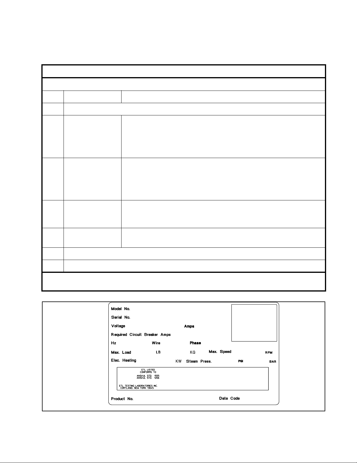
Instalación
H043I
380 – 415
15
50
35 16
500000
470
43
5
00000000000
SC35MN2CU20001
Guía de familiarización con los números de modelo
SC
35
M
(E)
(P)
(S)
(V)
N
(C)
(D)
(H)
(V)
2
(3)
(V)
C
Ejemplo de número de modelo:
Tipo de máquina C = Gabinete
Capacidad de la máquina (libras de peso en seco)
Tipo de control
eléctrico
Contador de
monedas (opcional)
Velocidad 2 = 2 velocidades
Características
eléctricas
M = Temporizador mecánico
E = Computadora MX/EDC
P = Computadora serie P †
S = Computadora serie S
V = Computadora serie V
N = Sin contador de monedas
C = W2000 (sólo modelos controlados por computadora)‡
D = Digital (sólo modelos con temporizador mecánico)
H = Deslizamiento horizontal (sólo modelos con temporizador mecánico)
V = Caída vertical (sólo modelos con temporizador mecánico)
3 = 3 velocidades
V = velocidad variable
Vea la tabla de designación de voltajes en esta sección.
SC35MN2CU20001
U2
0001
†Los modelos designados “PN” utilizan la computadora serie S
‡Los modelos designados “MC” están preparados para funcionar con un contador de monedas alternativo.
Serie de diseño
Identificación de opción (varía de máquina a máquina)
Figura 2
F232062(SP)
87
Page 90

Instalación
Especificaciones generales de máquinas de gabinete de montaje permanente
Modelos de 2 velocidades
Especificaciones 1825273550
Dimensiones generales
Anchura general, mm (plg) 660 (26) 660 (26) 737 (29) 765 (30-1/8) 865 (34-1/16)
Altura general, mm (plg) 1067 (42) 1143 (45) 1143 (45) 1200 (47-1/4) 1265 (49-3/4)
Profundidad general, mm (plg) 754 (29-11/16) 856 (33-11/16) 884 (34-13/16) 978 (38-1/2) 1067 (42)
Información de peso y transporte
Peso neto, kg (lb) 177 (390) 198 (435) 225 (495) 295 (650) 373 (820)
Peso de transporte doméstico, kg (lb) 194 (430) 214 (475) 250 (555) 320 (710) 437 (970)
Volumen de transporte doméstico,
3
m
(pie3)
Peso de transporte de exportación,
kg (lb)
Volumen de transporte de
3
exportación, m
Diámetro del cilindro, mm (plg) 533 (21) 533 (21) 610 (24) 667 (26-1/4) 762 (30)
Profundidad del cilindro, mm (plg) 349 (13-3/4) 457 (18-3/4) 406 (16) 467 (18-3/8) 508 (20)
Volumen del cilindro, lt (pie
Tamaño de las perforaciones, mm
(plg)
Área abierta de las perforaciones, % 17 17 23 17 18
Tamaño de la abertura de la puerta,
mm (plg)
Altura de la parte inferior de la
puerta desde el piso,
Consumo promedio de energía
eléctrica por ciclo, kW/hr
(pie3)
3
)
0,669 (23,9) 0,809 (28,9) 0,852 (30,1) 1,09 (39,0) 1,39 (49,8)
218 (480) 236 (525) 272 (605) 345 (760) 464 (1020)
1,32 (47,1) 1,01 (35,9) 1,07 (37,7) 1,32 (47,1) 1,92 (68,6)
Información del cilindro de lavado
78,1 (2,76) 106 (3,76) 117,9 (4,19) 163,1 (5,76) 232 (8,18)
4,76 (0,188) 4,76 (0,188) 4,76 (0,188) 4,76 (0,188) 4,76 (0,188)
Información de la abertura de la puerta
305 (12) 305 (12) 364 (14-11/32) 354 (13-15/16) 413 (16-1/4)
438 (17-1/4) 438 (17-1/4) 432 (17) 480 (19) 465 (18-1/4)
Consumo de energía eléctrica
0,20 0,25 0,25 0,30 0,42
Emisión de sonido nominal, dBA 60 63 63 64 66
Emisión de ruido de fondo, dBA 48 51 51 49 49
Carga HVAC promedio, BTU/hr 425 400 400 est. 510 700
88
F232062(SP)
Page 91

Instalación
Especificaciones generales de máquinas de gabinete de montaje permanente
Modelos de 2 velocidades (continuación)
Especificaciones 1825273550
Información del tren de transmisión
Número de motores en el tren de
transmisión
11111
Potencia de lavado/inversión, kW
(hp)
Potencia alta de extracción, kW (hp) 0,746 (1,0) 1,04 (1,4) 1,04 (1,4) 1,3 (1,8) 2,01 (2,7)
Velocidad de lavado/inversión, rpm 53 55 47 47 44
Velocidad alta de extracción, rpm 525 540 480 470 450
Fuerza centrífuga de lavado/
inversión, Gs
Fuerza centrífuga alta de extracción,
Gs
Interruptor de protección contra
vibraciones instalado
Tamaño de la conexión de entrada de
vapor, mm (plg)
Número de entradas de vapor 1 1 1 1 1
Vapor requerido para
elevar la temperatura del
agua de lavado 10° C, kg
(10° F, lb)
BAJO 0,50 (1,1) 0,64 (1,4) 0,68 (1,5) 0,95 (2,1) 1,3 (2,8
ALTO 0,54 (1,2) 0,73 (1,6) 0,77 (1,7) 1,3 (2,8) 1,7 (3,7)
0,13 (0,18) 0,19 (0,25) 0,19 (0,25) 0,30 (0,40) 0,41 (0,55)
Velocidades del cilindro
Datos de la fuerza centrífuga
0,85 0,90 0,75 0,82 0,825
82,1 86,9 80 82,3 86,3
Detección de balance
No corresp. No corresp. No corresp. No corresp. No corresp.
Calentamiento por vapor directo (opcional)
13 (1/2) 13 (1/2) 13 (1/2) 13 (1/2) 13 (1/2)
Consumo promedio de vapor por
ciclo, BHP
Capacidad de calentamiento
eléctrico total, kW
Número de elementos de
calentamiento eléctrico
Capacidad de los elementos de
calentamiento eléctrico, kW
F232062(SP)
0,66 0,87 0,94 1,4 1,9
Calentamiento eléctrico (opcional)
7,8 7,8 7,8 15,6 23,4
33369
2,6 2,6 2,6 2,6 2,6
89
Page 92

Instalación
Especificaciones generales de máquinas de gabinete de montaje permanente
Modelos de 3 velocidades
Especificaciones 18 35 50 80
Dimensiones generales
Anchura general, mm (plg) 660 (26) 765 (30-1/8) 865 (34-1/16) 1054 (41-1/2)
Altura general, mm (plg) 1067 (42) 1200 (47-1/4) 1265 (49-3/4) 1422 (56)
Profundidad general, mm (plg) 754 (29-11/16) 978 (38-1/2) 1067 (42) 1311 (51-5/8)
Información de peso y transporte
Peso neto, kg (lb) 182 (400) 307 (675) 432 (950) 727 (1600)
Peso de transporte doméstico, kg (lb) 195 (430) 355 (780) 450 (990) 743 (1650)
Volumen de transporte doméstico, m
(pie3)
3
0,669 (23,9) 1,09 (39,0) 1,39 (49,8) 2,19 (78,1)
Peso de transporte de exportación, kg
(lb)
Volumen de transporte de exportación,
3
m
(pie3)
Diámetro del cilindro, mm (plg) 533 (21) 667 (26-1/4) 762 (30) 914 (36)
Profundidad del cilindro, mm (plg) 349 (13-3/4) 467 (18-3/8) 508 (20) 559 (22)
3
Volumen del cilindro, lt (pie
Tamaño de las perforaciones, mm (plg) 4,76 (0,188) 4,76 (0,188) 4,76 (0,188) 4,76 (0,188)
Área abierta de las perforaciones, % 17 17 18 ---
Tamaño de la abertura de la puerta, mm
(plg)
Altura de la parte inferior de la puerta
desde el piso, mm (plg)
Consumo promedio de energía eléctrica
por ciclo, kW/hr
)
Información de la abertura de la puerta
223 (490) 357 (785) 523 (1150) 765 (1700)
1,32 (47,1) 1,32 (47,1) 1,92 (68,6) ---
Información del cilindro de lavado
78,1 (2,76) 163,1 (5,76) 232 (8,18) 354 (12,4)
305 (12) 354 (13-15/16) 413 (16-1/4) 470 (18-1/2)
438 (17-1/4) 480 (19) 465 (18-1/4) 546 (21-1/2)
Consumo de energía eléctrica
0,18 est 0,28 est 0,38 est 0,55 est
Emisión de sonido nominal, dBA 61 65 67 60 / 69
Emisión de ruido de fondo, dBA 48 49 49 47
Carga HVAC promedio, BTU/hr 440 525 725 900
90
F232062(SP)
Page 93

Instalación
Especificaciones generales de máquinas de gabinete de montaje permanente
Modelos de 3 velocidades (continuación)
Especificaciones 18 35 50 80
Información del tren de transmisión
Número de motores en el tren de
transmisión
Potencia de lavado/inversión, kW (hp) 0,13 (0,18) 0,30 (0,40) 0,67 (0,90) 0,75 (1,0)
Potencia mediana de extracción, kW (hp) 0,895 (1,2) 0,34 (0,45) 0,75 (1,0) 0,89 (1,2)
Potencia alta de extracción, kW (hp) 1,12 (1,5) 2,2 (3,0) 2,6 (3,5) 3,36 (4,5)
Velocidad de lavado/inversión, rpm 46 47 44 40
Velocidad mediana de extracción, rpm 330 75 60 64
Velocidad alta de extracción, rpm 661 591 561 530
Fuerza centrífuga de lavado/inversión,
Gs
Fuerza centrífuga mediana de
extracción, Gs
Fuerza centrífuga alta de extracción, Gs 130 130 134 143
Interruptor de protección contra
vibraciones instalado
1222
Velocidades del cilindro
Datos de la fuerza centrífuga
0,65 0,82 0,825 0,82
32,5 2,10 1,53 2,1
Detección de balance
No corresp. Estándar Estándar Estándar
Calentamiento por vapor directo (opcional)
Tamaño de la conexión de entrada de
vapor, mm (plg)
Número de entradas de vapor 1 1 1 1
Vapor requerido para elevar la
temperatura del agua de
lavado 10° C, kg (10° F, lb)
Consumo promedio de vapor por ciclo,
BHP
Capacidad de calentamiento eléctrico
total, kW
Número de elementos de calentamiento
eléctrico
Capacidad de los elementos de
calentamiento eléctrico, kW
F232062(SP)
BAJO 0,5 (1,1) 0,95 (2,1) 1,3 (2,8) 2,0 (4,4)
ALTO 0,54 (1,2) 1,3 (2,8) 1,7 (3,7) 2,9 (6,3)
13 (1/2) 13 (1/2) 13 (1/2) 13 (1/2)
0,66 1,4 1,9 3,1
Calentamiento eléctrico (opcional)
7,8 15,6 23,4 31,2
36912
2,6 2,6 2,6 2,6
91
Page 94

Instalación
Especificaciones generales de máquinas de gabinete de montaje permanente
Modelos de velocidad variable
Especificaciones 1827355080
Dimensiones generales
Anchura general, mm (plg) 660 (26) 737 (29) 765 (30-1/8) 865 (34-1/16) 1054 (41-1/2)
Altura general, mm (plg) 1067 (42) 1143 (45) 1200 (47-1/4) 1265 (49-3/4) 1422 (56)
Profundidad general, mm (plg) 754 (29-11/16) 884 (34-13/16) 978 (38-1/2) 1067 (42) 1311 (51-5/8)
Información de peso y transporte
Peso neto, kg (lb) 182 (404) 234 (520) 288 (640) 355 (788) 633 (1406)
Peso de transporte doméstico, kg (lb) 191 (424) 245 (545) 301 (670) 371 (818) 655 (1456)
Volumen de transporte doméstico,
3
m
(pie3)
0,669 (23,9) 0,852 (30,1) 1,09 (39,0) 1,39 (49,8) 2,69 (96,18)
Peso de transporte de exportación,
kg (lb)
Volumen de transporte de
3
exportación, m
Diámetro del cilindro, mm (plg) 533 (21) 610 (24) 667 (26-1/4) 762 (30) 914 (36)
Profundidad del cilindro, mm (plg) 349 (13-3/4) 406 (16) 467 (18-3/8) 508 (20) 559 (22)
Volumen del cilindro, lt (pie
Tamaño de las perforaciones, mm
(plg)
Área abierta de las perforaciones, % 17 23 17 18 27
Tamaño de la abertura de la puerta,
mm (plg)
Altura de la parte inferior de la
puerta desde el piso, mm (plg)
Consumo promedio de energía
eléctrica por ciclo, kW/hr
Emisión de sonido nominal, dBA N/A N/A N/A N/A N/A
(pie3)
3
)
222 (494) 275 (610) 338 (750) 448 (988) 678 (1506)
1,32 (47,1) 1,07 (37,7) 1,32 (47,1) 1,92 (68,6) 3,1 (109,4)
Información del cilindro de lavado
78,1 (2,76) 117,9 (4,19) 163,1 (5,76) 232 (8,18) 354 (12,4)
4,76 (0,188) 4,76 (0,188) 4,76 (0,188) 4,76 (0,188) 4,76 (0,188)
Información de la abertura de la puerta
305 (12) 364 (14-11/32) 354 (13-15/16) 413 (16-1/4) 470 (18-1/2)
438 (17-1/4) 432 (17) 480 (19) 465 (18-1/4) 546 (21-1/2)
Consumo de energía eléctrica
0,11 0,14 0,20 0,37
Emisión de ruido de fondo, dBA N/A N/A N/A N/A N/A
Carga HVAC promedio, BTU/hr 425 425 510 510 900
92
F232062(SP)
Page 95

Instalación
Especificaciones generales de máquinas de gabinete de montaje permanente
Modelos de velocidad variable (continuación)
Especificaciones 1827355080
Información del tren de transmisión
Número de motores en el tren de
transmisión
11111
Potencia del motor de transmisión,
kW (hp)
Velocidad suave de lavado/inversión,
rpm
Velocidad de lavado/inversión, rpm 52 48 46 43 40
Velocidad de distribución, rpm 82 77 73 68 63
Velocidad baja de extracción, rpm 366 343 328 307 280
Velocidad mediana de extracción,
rpm *
Velocidad alta de extracción, rpm 685 641 613 573 524
Fuerza centrífuga suave de lavado,
Gs
Fuerza centrífuga de lavado/
inversión, Gs
Fuerza centrífuga de distribución, Gs 2 2 2 2 2
Fuerza centrífuga baja de extracción,
Gs
0,75 (1) 0,75 (1) 1,5 (2) 1,5 (2) 3,7 (5)
Velocidades del cilindro
29 27 26 24 22
534 500 478 447 408
Datos de la fuerza centrífuga
0,25 0,25 0,25 0,25 0,25
0,8 0,8 0,8 0,8 0,8
40 40 40 40 40
Fuerza centrífuga mediana de
extracción, Gs
Fuerza centrífuga alta de extracción,
Gs
Interruptor de protección contra
vibraciones instalado
Calentamiento por vapor directo (opcional)
Tamaño de la conexión de entrada de
vapor, mm (plg)
Número de entradas de vapor 1 1 1 1 1
F232062(SP)
85 85 85 85 85
140 140 140 140 140
Detección de balance
No corresp. No corresp. Estándar Estándar Estándar
13 (1/2) 13 (1/2) 13 (1/2) 13 (1/2) 13 (1/2)
93
Page 96

Instalación
Especificaciones generales de máquinas de gabinete de montaje permanente
Modelos de velocidad variable (continuación)
Especificaciones 1827355080
Vapor requerido para
elevar la temperatura del
agua de lavado 10° C, kg
(10° F, lb)
Consumo promedio de vapor por
ciclo, BHP
Capacidad de calentamiento
eléctrico total, kW
Número de elementos de
calentamiento eléctrico
Capacidad de los elementos de
calentamiento eléctrico, kW
* La velocidad de extracción mediana no está disponible en los modelos equipados con control electrónico (EC)
BAJO 0,50 (1,1) 0,64 (1,4) 0,95 (2,1) 1,3 (2,8) 2,0 (4,4)
ALTO 0,64 (1,4) 0,86 (1,9) 1,2 (2,7) 1,7 (3,7) 2,9 (6,3)
0,72 0,96 1,4 1,9 3,1
Calentamiento eléctrico (opcional)
7,8 7,8 15,6 23,4 31,2
336
2,6 2,6 2,6 2,6 2,6
912
Dimensiones de la máquina
Las Figuras 3 a 8 ilustran las dimensiones de
los diferentes tipos de máquinas, comenzando
por el modelo de 18 libras y terminando con el
modelo de 80 libras.
Nota:
Las dimensiones que aparecen aquí sólo
son para propósitos de planificación. Son
valores aproximados y están sujetos a las
tolerancias normales de fabricación. Si tiene
necesidad de conocer las dimensiones exactas,
póngase en contacto con su distribuidor o
fabricante. Nos reservamos el derecho de hacer
cambios en cualquier momento sin previo
aviso.
94
F232062(SP)
Page 97

Surtidor de suministros
Instalación
Tira de conexiones de señales de suministro
de productos químicos externos (sólo OPL)
Bloque de alimentación
de entrada
Máquinas de 18 libras de
capacidad
Entrada de agua fría
Entrada de agua caliente
Entrada de agua adicional
(opcional)
Entradas de suministro de
productos químicos externos
(sólo OPL)
Cortacircuitos de vacío
Salida de desagüe
H001IS3A
F232062(SP)
Figura 3
95
Page 98

Instalación
Dimensiones de la máquina
(continuación)
Surtidor de suministros
Tira de conexiones de señales de suministro
de productos químicos externos (sólo OPL)
Bloque de alimentación
de entrada
Máquinas de 25 libras de
capacidad
Entrada de agua fría
Entrada de agua caliente
Entrada de agua adicional
(opcional)
Entradas de suministro de
productos químicos externos
(sólo OPL)
Cortacircuitos de vacío
Salida de desagüe
H002IS3A
96
Figura 4
F232062(SP)
Page 99

Surtidor de suministros
Instalación
Tira de conexiones de señales de suministro
de productos químicos externos (sólo OPL)
Bloque de alimentación
de entrada
Máquinas de 27 libras de
capacidad
Entrada de agua fría
Entrada de agua caliente
Entrada de agua adicional
(opcional)
Entradas de suministro de
productos químicos externos
(sólo OPL)
Cortacircuitos de vacío
Salida de desagüe
H003IS3A
F232062(SP)
Figura 5
97
Page 100

Instalación
Dimensiones de la máquina
(continuación)
Surtidor de suministros
Tira de conexiones de señales de suministro
de productos químicos externos (sólo OPL)
Bloque de alimentación
de entrada
Máquinas de 35 libras de
capacidad
Entrada de agua fría
Entrada de agua caliente
Entrada de agua adicional
(opcional)
Entradas de suministro de
productos químicos externos
(sólo OPL)
Cortacircuitos de vacío
Salida de desagüe
H004IS3A
98
Figura 6
F232062(SP)
 Loading...