

Alliance Laundry Systems HC18SN2, UC40VN2, SC35VN2, UC20PN2, HC18VC2 Operation & Maintenance Manual
...
Washer-Extractors
Cabinet Hardmount
S, P, and V-Series Microcomputers Coin and
Non-Coin Models
Refer to Page 3 for Model Identification
NOTA: El manual en
español aparece después
del manual en inglés.
Operation/Maintenance
Keep These Instructions for Future Reference.
(If this machine changes ownership, this manual must accompany machine.)
www.comlaundry.com
CHM166C
Part No. F232137R2
April 2002


Table of
Contents
Introduction......................................................................................... 3
Model Identification ............................................................................. 3
Nameplate Location.............................................................................. 4
Replacement Parts ................................................................................ 4
Customer Service.................................................................................. 4
Safety Information.............................................................................. 5
Important Safety Instructions ............................................................... 5
Operation............................................................................................. 7
Control Panel ........................................................................................ 7
Display Indications............................................................................... 8
Operating Instructions .......................................................................... 12
Maintenance ........................................................................................ 15
Daily ..................................................................................................... 15
Beginning of Day............................................................................. 15
End of Day ....................................................................................... 15
Weekly.................................................................................................. 16
Monthly................................................................................................. 16
Quarterly............................................................................................... 19
Care of Stainless Steel.......................................................................... 20
© Copyright 2002, Alliance Laundry Systems LLC
All rights reserved. No part of the contents of this book may be reproduced or transmitted in any form or by any
means without the expressed written consent of the publisher.
F232137
© Copyright, Alliance Laundry Systems LLC – DO NOT COPY or TRANSMIT
1

Notes
2
© Copyright, Alliance Laundry Systems LLC – DO NOT COPY or TRANSMIT
F232137
Introduction
Model Identification
Information in this manual is applicable to these models:
HC18SN2 HC27VX2 HC50SN2 SC35VN2 UC20PN2 UC40VN2
HC18VC2 HC30SN2 HC50VC2 SC35VNV UC20VN2 UC40VNV
HC18VX2 HC30VC2 HC50VX2 SC40VN2 UC27PN2 UC50PN2
HC20SN2 HC30VX2 HC80VCV SC40VNV UC27VN2 UC50VN2
HC20VC2 HC35SN2 HC80VNV SC50VN2 UC30PN2 UC50VNV
HC20VX2 HC35VC2 HC80VXV SC50VNV UC30VN2 UC80VNV
HC25VC2 HC35VX2 SC18VN2 SC80VNV UC35PN2 UC125VNV
HC25VX2 HC40SN2 SC20VN2 SC125VNV UC35VN2
HC27SN2 HC40VC2 SC27VN2 UC18PN2 UC35VNV
HC27VC2 HC40VX2 SC30VN2 UC18VN2 UC40PN2
F232137
© Copyright, Alliance Laundry Systems LLC – DO NOT COPY or TRANSMIT
3
Introduction
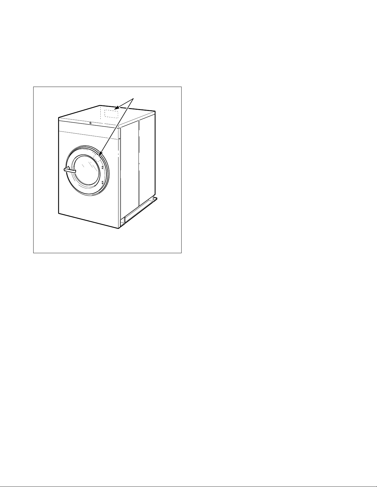
Nameplate Location
The nameplate is located at the rear of the machine and
inside door. Always provide the machine’s serial
number and model number when ordering parts or
when seeking technical assistance.
1
Replacement Parts
If literature or replacement parts are required, contact
the source from whom the machine was purchased or
contact Alliance Laundry Systems at (920) 748-3950
for the name and address of the nearest authorized
parts distributor.
Customer Service
For technical assistance, call any of the following
numbers:
(850) 718-1025
(850) 718-1026
Marianna, Florida U.S.A.
(920) 748-3121
Ripon, Wisconsin U.S.A.
1 Nameplate
CHM167R
Figure 1
4
© Copyright, Alliance Laundry Systems LLC – DO NOT COPY or TRANSMIT
F232137
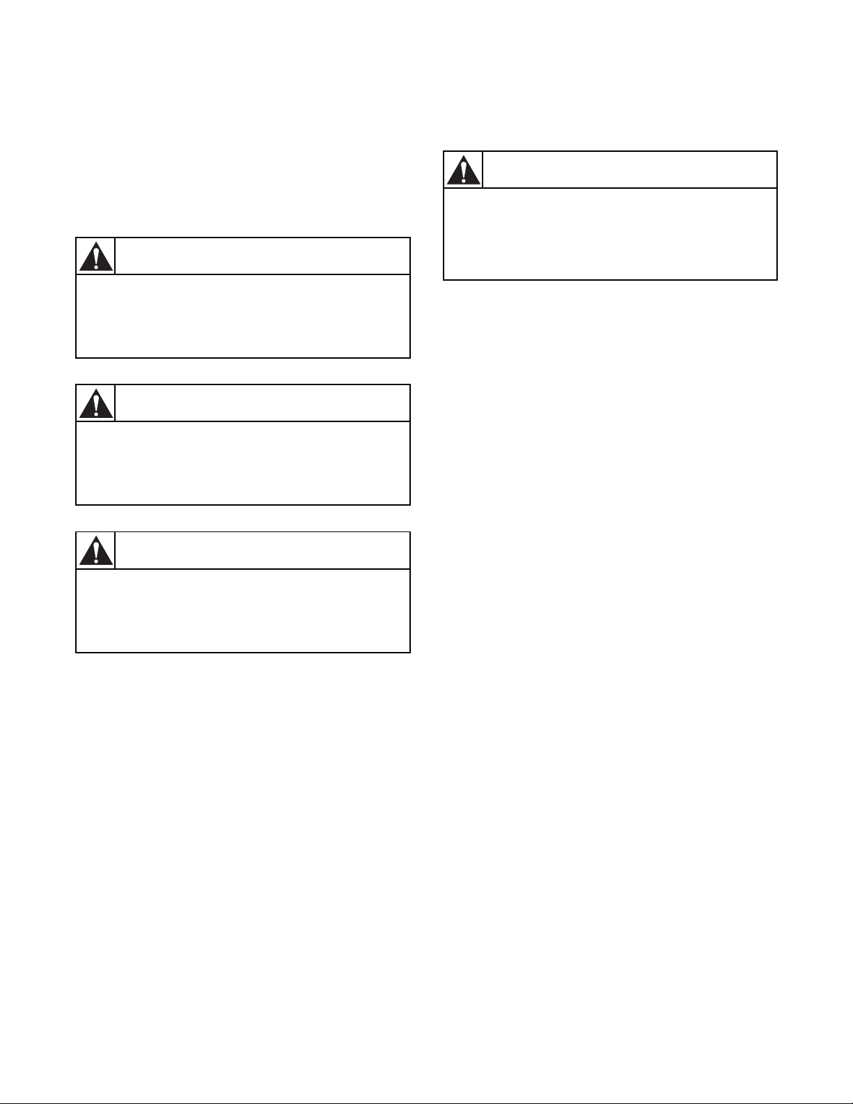
Safety Information
DANGER indicates the presence of a
hazard that will cause severe personal
injury, death, or substantial property
damage if the danger is ignored.
DANGER
WARNING indicates the presence of a
hazard that can cause severe personal
injury, death, or substantial property
damage if the warning is ignored.
WARNING
CAUTION indicates the presence of a
hazard that will or can cause minor
personal injury or property damage if the
caution is ignored.
CAUTION
Precautionary statements (“DANGER”, “WA R N I N G ”
and “CAUTION”), followed by specific instructions,
are found in this manual and on machine decals. These
precautions are intended for the personal safety of the
operator, user, servicer and those maintaining the
machine.
Important Safety Instructions
WARNING
To reduce the risk of fire, electric shock,
serious injury or death to persons when
using your washer, follow these basic
precautions:
W023E
1. Read all instructions before using the washer.
2. Refer to the Grounding Instructions in the
Installation Manual for the proper grounding of
the washer.
3. Do not wash textiles that have been previously
cleaned in, washed in, soaked in, or spotted with
gasoline, dry-cleaning solvents, or other
flammable or explosive substances as they give
off vapors that could ignite or explode.
4. Do not add gasoline, dry-cleaning solvents, or
other flammable or explosive substances to the
wash water. These substances give off vapors that
could ignite or explode.
Additional precautionary statements (“IMPORTANT”
and “NOTE”) are followed by specific instructions.
IMPORTANT: The word “IMPORTANT” is used
to inform the reader of specific procedures where
minor machine damage will occur if the procedure
is not followed.
NOTE: The word “NOTE” is used to communicate
installation, operation, maintenance or servicing
information that is important but not hazard
related.
5. Under certain conditions, hydrogen gas may be
produced in a hot water system that has not been
used for two weeks or more. HYDROGEN GAS
IS EXPLOSIVE. If the hot water system has not
been used for such a period, before using a
washing machine or combination washer-dryer,
turn on all hot water faucets and let the water
flow from each for several minutes. This will
release any accumulated hydrogen gas. The gas is
flammable; do not smoke or use an open flame
during this time.
6. Do not allow children to play on or in the washer.
Close supervision of children is necessary when
the washer is used near children. This is a safety
rule for all appliances.
7. Before the washer is removed from service or
discarded, remove the door to the washing
compartment.
8. Do not reach into the washer if the wash drum is
moving.
F232137
© Copyright, Alliance Laundry Systems LLC – DO NOT COPY or TRANSMIT
5

Safety Information
9. Do not install or store the washer where it will be
exposed to water and/or weather.
10. Do not tamper with the controls.
11. Do not repair or replace any part of the washer, or
attempt any servicing unless specifically
recommended in the user-maintenance
instructions or in published user-repair
instructions that the user understands and has the
skills to carry out.
12. To reduce the risk of an electric shock or fire, DO
NOT use an extension cord or an adapter to
connect the washer to the electrical power source.
13. Use washer only for its intended purpose,
washing textiles.
14. ALWAYS disconnect the washer from electrical
supply before attempting any service. Disconnect
the power cord by grasping the plug, not the cord.
15. Install the washer according to the Installation
Instructions. All connections for water, drain,
electrical power and grounding must comply
with local codes and be made by licensed
personnel when required.
16. To reduce the risk of fire, textiles which have
traces of any flammable substances such as
vegetable oil, cooking oil, machine oil,
flammable chemicals, thinner, etc. or anything
containing wax or chemicals such as in mops and
cleaning cloths, must not be put into the washer.
These flammable substances may cause the
fabric to catch on fire by itself.
17. Do not use fabric softeners or products to
eliminate static unless recommended by the
manufacturer of the fabric softener or product.
18. Keep washer in good condition. Bumping or
dropping the washer can damage safety features.
If this occurs, have washer checked by a qualified
service person.
19. Replace worn power cords and/or loose plugs.
20. Be sure water connections have a shut-off valve
and that fill hose connections are tight. CLOSE
the shut-off valves at the end of each wash day.
21. Loading door MUST BE CLOSED any time the
washer is to fill, tumble or spin. DO NOT
bypass the loading door switch by permitting the
washer to operate with the loading door open.
22. Always read and follow manufacturer’s
instructions on packages of laundry and cleaning
aids. Heed all warnings or precautions. To reduce
the risk of poisoning or chemical burns, keep
them out of the reach of children at all times
(preferably in a locked cabinet).
23. Always follow the fabric care instructions
supplied by the textile manufacturer.
24. Never operate the washer with any guards
and/or panels removed.
25. DO NOT operate the washer with missing or
broken parts.
26. DO NOT bypass any safety devices.
27. Failure to install, maintain and/or operate this
washer according to the manufacturer’s
instructions may result in conditions which can
produce bodily injury and/or property damage.
NOTE: The WARNINGS and IMPORTANT
SAFETY INSTRUCTIONS appearing in this
manual are not meant to cover all possible
conditions and situations that may occur. Common
sense, caution and care must be exercised when
installing, maintaining or operating the washer.
Any problems or conditions not understood should be
reported to the dealer, distributor, service agent or the
manufacturer.
6
© Copyright, Alliance Laundry Systems LLC – DO NOT COPY or TRANSMIT
F232137
Operation
Up Down Start Stop
1
2
3
4
5
6
8 7
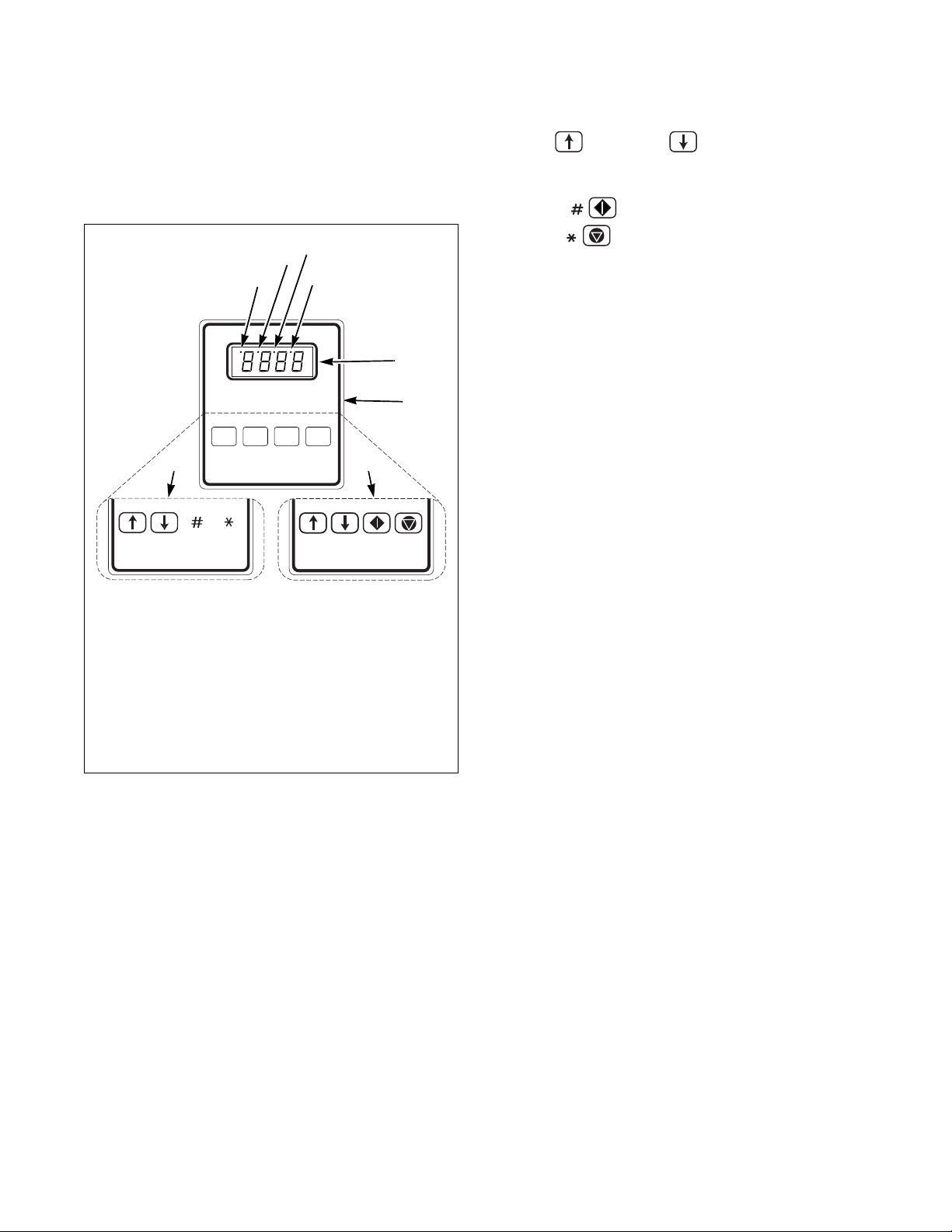
Control Panel
Figure 2 shows the control panel for S, P and
V-computer machines.
1 Out-of-Balance Condition for VCV, VXV
2 High Water Level
3 Medium Water Level for V-Series
4 Low Water Level
5 LED Display
6 Keys for Standard OPL
7 Keys for Icon OPL
8 Keys for VC2, VCV, VX2, VXV
The Up and Down keys are used in cycle
selection. Press these keys to move among cycles from
smaller to greater, or greater to smaller.
The Start key is used to start a cycle.
The Stop key is not active in normal Run
Mode. In Run Mode it is used only for stopping test
cycle.
The LED display informs operator of various
functions throughout operation of machine. Refer to
tables on the following pages for displays and their
meanings. Indicator lights in LED display indicate
out-of-balance conditions and water levels. Refer to
Figure 2.
B161R
Figure 2
F232137
© Copyright, Alliance Laundry Systems LLC – DO NOT COPY or TRANSMIT
7
Operation
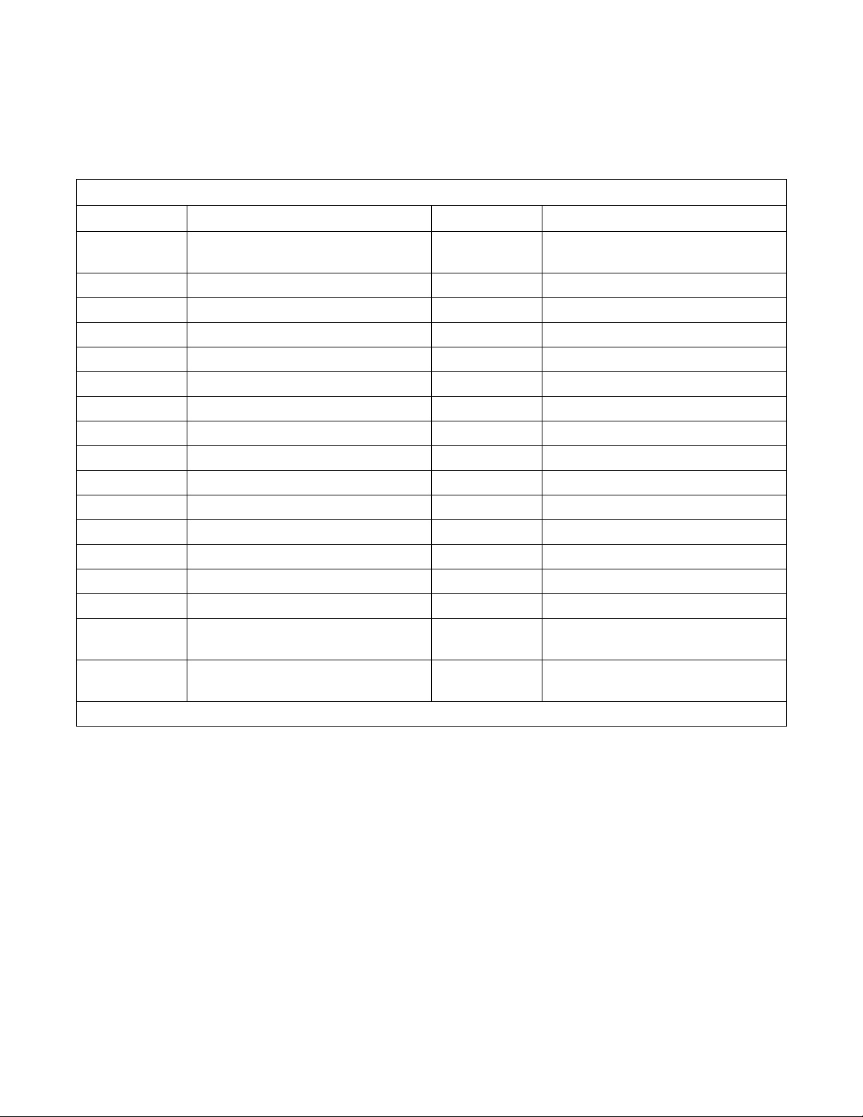
Display Indications
Table 1 through Ta b le 4 list the various displays and
what they mean. The operator should become familiar
with these computer displays.
Display Indications for S-Series – Non-Coin
Display Meaning Display Meaning
S-05 Program identification code (ROM)
(this is an example only)
HoLd Wait...power has just been turned on HFIL Hot fill
CY Cycle (followed by two-digit number) LOLE Low water level
CHEC/CYC* Test cycle selected HILE High water level
FAr Degrees Fahrenheit SUP1 Supply 1
CEL Degrees Celsius SUP2 Supply 2
PrE Prewash segment (1st of 8 segments) SUP3 Supply 3
UASH Wash segment (2nd of 8 segments) SUP4 Supply 4
FIL1 First rinse (3rd of 8 segments) SUP5 Supply 5 (supply 1 and 2)
FIL2 Second rinse (4th of 8 segments) SUP6 Supply 6 (supply 2 and 3)
FIL3 Third rinse (5th of 8 segments) SUP7 Supply 7 (supply 3 and 4)
FIL4 Fourth rinse (6th of 8 segments) STOP Stop routine
FIL5 Fifth rinse (7th of 8 segments) SdLY Spin coast delay
FIL6 Sixth rinse (8th of 8 segments) donE Cycle and stop routine have ended
CFIL Cold fill door Door not properly closed
SPIn/tI
nE* Reads “SPIn” for one second, then
nE” followed by time for spin
“tI
bFIL Warm fill (both hot and cold)
FILL/STOP* Programmed water level not reached
after 30 minutes
tSFL Temperature sensor failure or
temperature out of range
*Display indications separated by a slash (/) represent an alternating display.
8
© Copyright, Alliance Laundry Systems LLC – DO NOT COPY or TRANSMIT
FULL The computer detects low water level or
Table 1
higher when none should be present
F232137
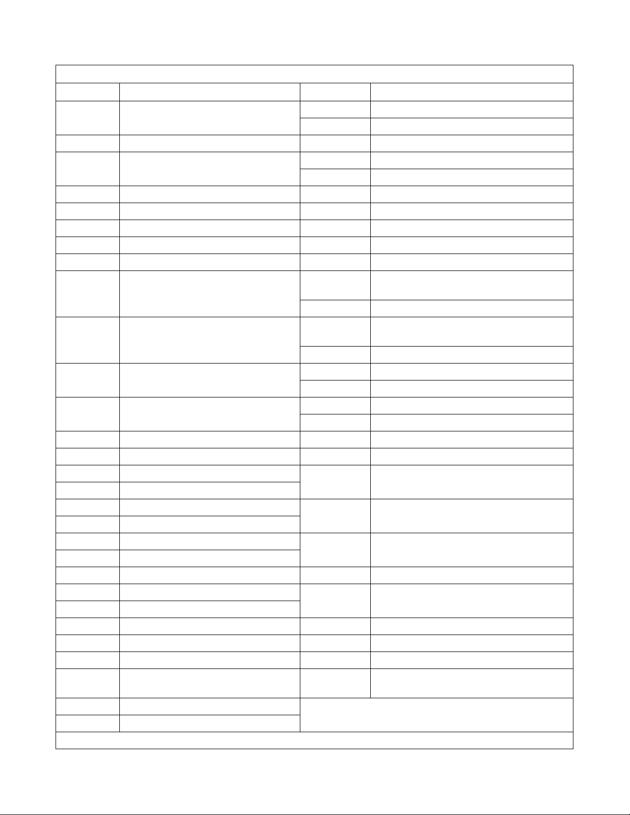
Operation
Display Indications for V-Series – Coin
Display Meaning Display Meaning
FC 5 Program identification code (ROM)
(this is an example only)
HoLd Wait...power has just been turned on
PAY/(price)* Pay (flashes alternately with start price if
“FLSH” SETUP option is enabled)
CY Cycle (followed by two-digit number) SUP1 Supply 1
tESt/CYC* Test cycle selected SUP2 Supply 2
FAr Degrees Fahrenheit SUP3 Supply 3
CEL Degrees Celsius SUP5 Supply 5 (supply 1 and 2)
HEAt Auxiliary heat enabled SUP6 Supply 6 (supply 2 and 3)
noHt Auxiliary heat disabled drAI/dISt* Distribution (load balancing before extract)
Strt/A
nt* Start amount – flashes briefly before
showing vend price in Setup Mode
Con1/deno* Coin 1 value – flashes briefly before
showing value of coin 1 in Setup Mode
Con2/deno* Coin 2 value – flashes briefly before
showing value of coin 2 in Setup Mode
PrE Prewash segment (1st of 8 segments) bAL/FAIL* Balance routine failed during test cycle
UASH Wash segment (2nd of 8 segments) SHUT/door* Door not properly closed
FIL1 First fill (3rd of 8 segments) CANt/OPEN* Computer cannot unlock door after five
FIL2 Second fill (4th of 8 segments)
FIL3 Third fill (5th of 8 segments) FILL/STOP* Programmed water level not reached after
FIL4 Fourth fill (6th of 8 segments)
FIL5 Fifth fill (7th of 8 segments) FULL The computer detects low water level or higher
FIL6 Sixth fill (8th of 8 segments)
AFIL Auxiliary fill dFLt Drive fault detected (Variable-speed only)
bFIL Warm fill (both hot and cold) tSFL Temperature sensor failure or temperature out
CFIL Cold fill
bLCH Add bleach (for supply 2 only) bAL? Special factory balance setup mode
1Pr One vend price – all cycles SPC? Special factory valve flush mode
16Pr 16 vend prices – one per cycle SPIN Spin in test cycle (2 speed only)
CHEC/
CYC*
For Wash speed forward in test cycle
FrEE “Free” cycle option
*Display indications separated by a slash (/) represent an alternating display.
Test cycle selected (same as tESt/CYC) rEv Reverse wash speed in test cycle
HFIL Hot fill
Lo Low water level
nEd Medium water level
HI High water level
SUP0 No supplies
(Variable-speed only)
drAI/For* Drain step (low speed forward in test cycle)
SPIn/tInE* Reads “SPIn” for one second, then “tInE”
followed by time for spin
SdLY Spin coast delay
STOP Stop routine
donE Cycle and stop routine have ended
HI 1 Low spin in test cycle (Variable-speed only)
HI 2 High spin in test cycle (Variable-speed only)
attempts
30 minutes
when none should be present
of range
F232137
Table 2
© Copyright, Alliance Laundry Systems LLC – DO NOT COPY or TRANSMIT
9
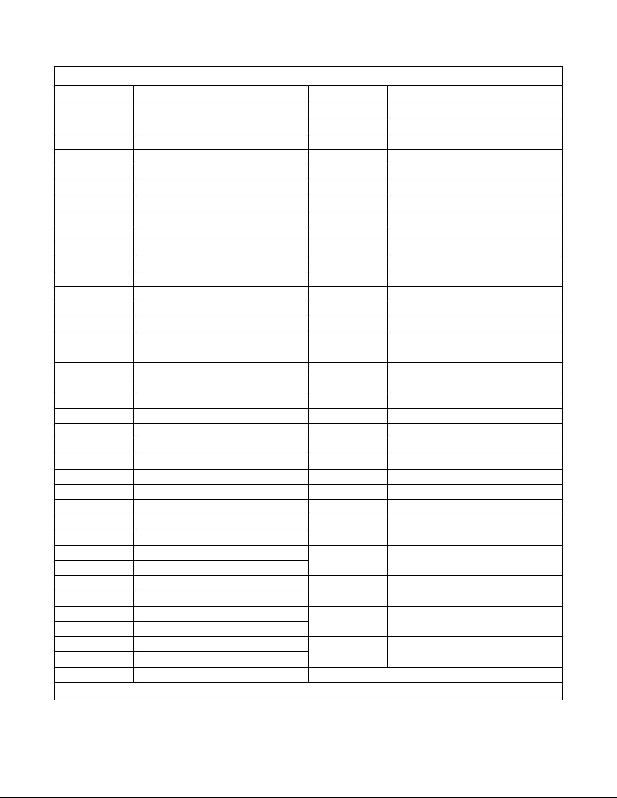
Operation
Display Indications for V-Series – Non-Coin
Display Meaning Display Meaning
FP 1 Program identification code (ROM)
(this is an example only)
HoLd Wait...power has just been turned on SUP1 Supply 1
CY Cycle (followed by two-digit number) SUP2 Supply 2
tESt/CYC* Test cycle selected SUP3 Supply 3
FAr Degrees Fahrenheit SUP4 Supply 4
CEL Degrees Celsius SUP5 Supply 5 (Setup option)
HEAt Auxiliary heat enabled SUP6 Supply 6 (supply 1 and 5)
noHt Auxiliary heat disabled SUP7 Supply 7 (supply 3 and 4)
tFIL Temperature-controlled fill enabled SLo/For Gentle wash speed, forward direction
ntFL Temperature-controlled fill disabled SLo/rEv Gentle wash speed, reverse direction
CooL Automatic cool-down enabled nor
noCL Automatic cool-down disabled nor
Ag 1 Agitation 1 selected (90% agitation) drAI Drain enabled
Ag 2 Agitation 2 selected (33% agitation) nodr Drain disabled
Ag 3 Agitation 3 selected (10% agitation) dISt Distribution (load balancing before
Ag 4 Agitation 4 selected (6.7% agitation) SPIn/tI
AgSn Agitation speed normal
AgSL Agitation speed low SPn1 Lowest of three spins
PU
nP Pump output enabled (future use only) SPn2 Middle of three spins
nP
nP Pump output disabled (future use only) SPn3 Highest of three spins
PrE Prewash segment (1st of 11 segments) STOP Stop routine
UASH Wash segment (2nd of 11 segments) SdLY Spin coast delay
FIL1 First fill (3rd of 11 segments) donE Cycle and stop routine have ended
FIL2 Second fill (4th of 11 segments) dFLt Drive fault detected
FIL3 Third fill (5th of 11 segments) door Door not properly closed
FIL4 Fourth fill (6th of 11 segments) bAL/FAIL* Balancing routine failed during test cycle
FIL5 Fifth fill (7th of 11 segments)
FIL6 Sixth fill (8th of 11 segments) FILL/STOP* Programmed water level not reached
FIL7 Seventh fill (9th of 11 segments)
FIL8 Eighth fill (10th of 11 segments) FULL The computer detects low water level or
FIL9 Ninth fill (11th of 11 segments)
CFIL Cold fill rotA Computer detects possible rotation of
bFIL Warm fill (both hot and cold)
HFIL Hot fill tSFL Temperature sensor failure or
AFIL Auxiliary fill (Setup option)
Lo Low water level
*Display indications separated by a slash (/) represent a flashing display.
nEd Medium water level
HI High water level
n/For Normal wash speed, forward direction
n/rEv Normal wash speed, reverse direction
extract)
nE* Reads “SPIn” for one second, then
nE” followed by time for spin
“tI
after 10 attempts to balance load
after 30 minutes
higher when none should be present
motor when there should be none
temperature out of range
10
Table 3
© Copyright, Alliance Laundry Systems LLC – DO NOT COPY or TRANSMIT
F232137
Display Indications for V-Series Two Speed – Non-Coin
Display Meaning Display Meaning
Operation
F23n Program identification code (ROM)
(this is an example only)
HoLd Wait...power has just been turned on FIL8 Eighth fill (10th of 11 segments)
CY Cycle (followed by two-digit number) FIL9 Ninth fill (11th of 11 segments)
tESt/CYC* Test cycle selected CFIL Cold fill
FAr Degrees Fahrenheit bFIL Warm fill (both hot and cold)
CEL Degrees Celsius HFIL Hot fill
HEAt Auxiliary heat enabled AFIL Auxiliary fill (Setup option)
noHt Auxiliary heat disabled Lo Low water level
tFIL Temperature-controlled fill enabled
ntFL Temperature-controlled fill disabled HI High water level
CooL Automatic cool-down enabled SUP1 Supply 1
noCL Automatic cool-down disabled SUP2 Supply 2
Ag 1 Agitation 1 selected (90% agitation) SUP3 Supply 3
Ag 2 Agitation 2 selected (33% agitation) SUP4 Supply 4
Ag 3 Agitation 3 selected (10% agitation) SUP5 Supply 5 (or Setup option)
Ag 4 Agitation 4 selected (6.7% agitation) SUP6 Supply 6 (supply 1 and 5)
FIL6 Sixth fill (8th of 11 segments)
FIL7 Seventh fill (9th of 11 segments)
nEd Medium water level
PU
nP Pump output enabled (future use only) SUP7 Supply 7 (supply 3 and 4)
nP Pump output disabled (future use only) For Wash speed, forward direction
nP
PrE Prewash segment (1st of 11 segments) rEv Wash speed, reverse direction
UASH Wash segment (2nd of 11 segments) drAI Drain enabled
FIL1 First fill (3rd of 11 segments) nodr Drain disabled
FIL2 Second fill (4th of 11 segments) STOP Stop routine
FIL3 Third fill (5th of 11 segments) SdLY Spin coast delay
FIL4 Fourth fill (6th of 11 segments) donE Cycle and stop routine have ended
FIL5 Fifth fill (7th of 11 segments) door Door not properly closed
FULL The computer detects low water level or
higher when none should be present
tSFL Temperature sensor failure or
temperature out of range
*Display indications separated by a slash (/) represent a flashing display.
FILL/STOP* Programmed water level not reached
after 30 minutes
SPIn/tI
nE* Reads “SPIn” for one second, then
nE” followed by time for spin
“tI
Table 4
F232137
© Copyright, Alliance Laundry Systems LLC – DO NOT COPY or TRANSMIT
11
Operation
Operating Instructions
1. Turn on main power source (circuit breaker).
For non-coin models: Turn on the On/Off switch
on the front panel to the On position.
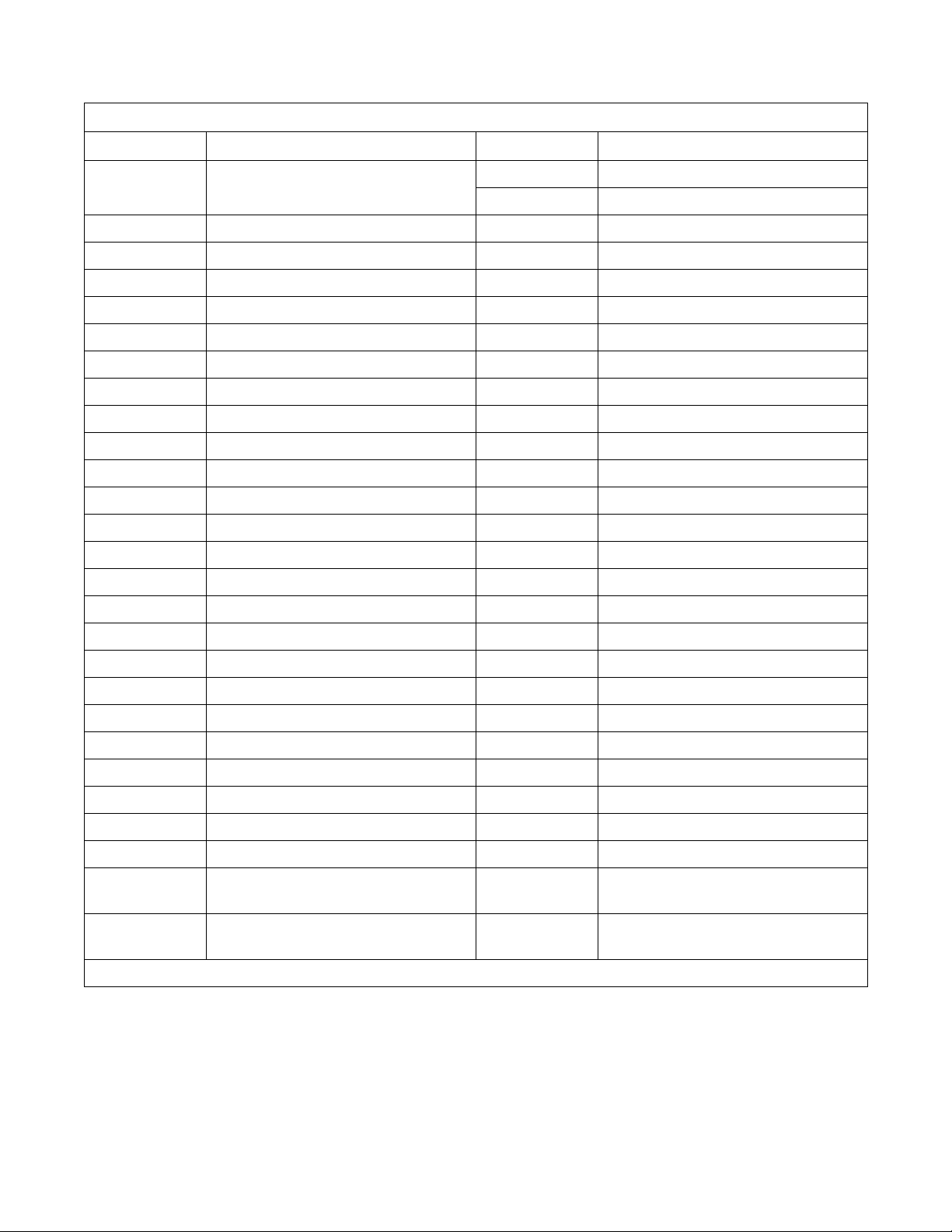
2. Push button and turn handle clockwise to open.
Refer to Figure 3.
U001I
Figure 3
For non-coin models: Press and hold the DOOR
UNLOCK button on the left side of the control
panel while performing the above step. Refer to
Figure 3 and Figure 4.
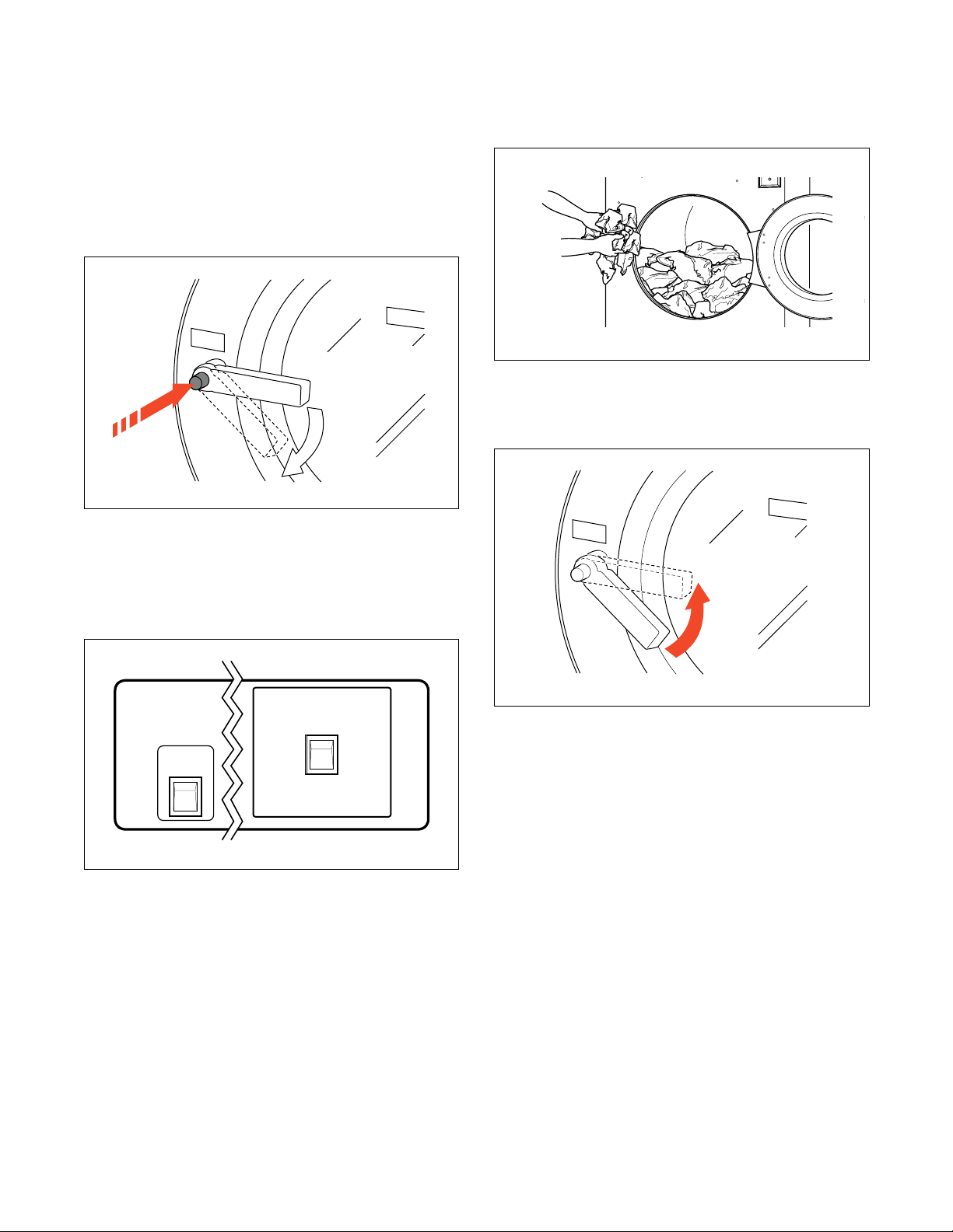
3. Load to capacity whenever possible. DO NOT
OVERLOAD. Refer to Figure 5.
U003I
Figure 5
4. Close door and turn handle counterclockwise
until button pops out. Refer to Figure 6.
U001I
DOOR UNLOCK
Figure 4
U005I
U005I
On
Off
U135R
U135R
Figure 6
12
© Copyright, Alliance Laundry Systems LLC – DO NOT COPY or TRANSMIT
F232137
 Loading...