

Page 1
Front Load
Washers
Metered Commercial
OPERATING INSTRUCTIO
Select Wash Temperature
1.
Select Fabric Type
2.
Load Supply Dispenser (See
3.
Insert Coin(s) / Card.
3
5.
1
2
DISPENSER INSTRUCTION
Open Dispenser
1.
Detergent
1.
Compartment (as
685942
2
Detergent
2.
Close Dispenser
3
685557
Installation and Operation
H236I
NOTA: El manual en español aparece después del manual en inglés.
Part No. 685945R5
October 1999
Page 2

Page 3

KEEP THESE INSTRUCTIONS FOR FUTURE REFERENCE. (If the washer changes ownership,
be sure this manual accompanies the washer.)
WARNING
For your safety and to reduce the risk of
fire or an explosion, do not store or use
gasoline or other flammable vapors and
liquids in the vicinity of this or any other
appliance.
© Copyright 1999, Alliance Laundry Systems LLC
All rights reserved. No part of the co ntents of this book may be reproduced or transmi t ted i n any form or b y a ny means
without the expressed written consent of the publisher.
685945 1
Page 4

Table of
Contents
Replacement Parts ...............................................................................2
Important Safety Instructions .............................................................3
Dimensions and Specifications.............................................................5
Additional Security...............................................................................5
Coin Slide Guards.................................................................................5
Washer Slide Extension .......................................................................6
Before You Start....................................................................................7
Installing the Washer
Step 1: Position Washer Near Installation Area..................................7
Step 2: Connect Water Inlet Hoses.....................................................8
Step 3: Connect Drain Hose to Drain Receptacle...............................9
Step 4: Remove the Shock Sleeves and Shipping Brace ..................10
Step 5: Position and Level the Washer.............................................10
Step 6: Wipe Out Inside of Wash Drum...........................................11
Step 7: Plug in the Washer................................................................11
Step 8: Check Installation.................................................................11
Moving Washer to a New Location ..................................................12
Electrical Requirements ....................................................................13
Water Supply Requirements..............................................................14
Operation Instructions for Electromechanical Washers
Step 1: Load Laundry........................................................................15
Step 2: Close Loading Door..............................................................15
Step 3: Add Laundry Supplies..........................................................15
Step 4: Set WASH/RINSE Temperatures.........................................16
Step 5: Select Fabric Selector...........................................................16
Step 6: Insert Money.........................................................................16
Indicator Lights.................................................................................16
Operation Instructions for Electronic Control Washers
Step 1: Load Laundry........................................................................17
Step 2: Close Loading Door..............................................................17
Step 3: Add Laundry Supplies..........................................................17
Step 4: Set Fabric Selector................................................................18
Step 5: Set Wash Temperature..........................................................18
Step 6: Insert Coin(s) or Card ...........................................................18
Step 7: Start Washer..........................................................................18
Indicator Lights.................................................................................19
Maintenance
Cold Weather Care ...........................................................................20
Care of Your Washer .......................................................................20
Vacations and Extended Non-Use....................................................20
Before You Call For Service..............................................................21
Information for Handy Reference ....................................................22
Installer Checklist ............................................................... Back Cover
Replacement Parts . . .
If replacement part s are required, contact the source from
where you purchased your washer, or contact:
2 685945
Alliance Laundry Systems LLC
Shepard Street
P.O. Box 990
Ripon, WI 54971-0990
Phone: (920) 748-3950
for the name and address of the nearest authorized parts
distributor.
Page 5

IMPORTANT SAFETY INSTRUCTIONS
(SAVE THESE INSTRUCTIONS)
W ARNING
To reduce the risk of fire, electric shock,
serious injury or death to persons when
using your washer , follow these basic
precautions:
W023E
1. Read all instructions before using the washer.
2. Refer to the GROUNDING INSTRUCTIONS
in the INSTALLATION manual for the proper
grounding of the washer.
3. Do not wash articles that have been previously
cleaned in, washed in, soaked in, or spotted
with gasoline, dry-cleaning solvents, or other
flammable or explosive substances as they give
off vapors that could ignite or explode.
4. Do not add gasoline, dry-cleaning solvents, or
other flammable or explosive substances to the
wash water. These substances give off vapors
that could ignite or explode.
5. Under certain conditions, hydrogen gas may be
produced in a hot water system that has not
been used for two weeks or more. HYDROGEN
GAS IS EXPLOSIVE. If the hot water system
has not been used for such a period, before
using a washing machine or combination
washer-dryer, turn on al l hot water f aucets and
let the water flow from each for several
minutes. This will release any accumulated
hydrogen gas. The gas is flammable, do not
smoke or use an open flame during this time.
6. Do not allow children to play on or in the
washer. Cl ose supervi sion of children is
necessary when the washer is used near
children. This is a safety rule for all appliances.
7. Before the washer is removed from service or
discarded, remove the door to the washing
compartment.
8. Do not reach into the washer if the wash drum
is moving.
9. Do not install or store the washer where it will
be exposed to water and/or weather.
10. Do not tamper with the controls.
11. Do not repair or r eplace any part of the washer ,
or attempt any servicing unless specifically
recommended in the user-maintenance
instructions or in published user-repair
instructions that you understand and have the
skills to carry out.
12. To reduce the risk of an electric shock or fire,
DO NOT use an extension cord or an adapter
to connect the washer to the electrical power
source.
13. Use your washer only for its intended purpose,
washing clothes.
14. ALWAYS disconnect the washer from
electrical supply be fore a ttempti ng any s ervice .
Disconnect the power cord by grasping the
plug, not the cord.
15. Install the washer according to the
INSTALLATION INSTRUCTIONS. All
connections for water, drain, electrical power
and grounding must comply with local codes
and be made by licensed personnel when
required. Do not do it yourse lf unles s you kn ow
how!
16. To reduce the risk of fire, clothes which have
traces of any flammable substances such as
vegetable oil, cooking oil, machine oil,
flammable chemicals, thinner, etc. or anything
containing wax or chemicals such as in mops
and cleaning cloths, must not be put into the
washer. These flammable substanc es may cause
the fabric to catch on fi re by itself .
17. Do not use fabric softeners or products to
eliminate static unless recommended by the
manufacturer of the fabric softener or product.
18. Keep your washer in good condition. Bumping
or dropping the washer can damage safety
features. If this occurs, have your washer
checked by a qualified service person.
19. If the supply cord is damaged, it must be
replaced by a special cord or assembly
available from the manufacturer or its service
agent.
20. Be sure wat er connectio ns have a shut-of f valve
and that fill ho se conne ction s a re ti ght. CLOSE
the shut-off valves at the end of each wash day.
(continued)
685945 3
Page 6

21. Loading door MUST BE CLOSED any time
the washer is to fill, tumble or spin. DO NOT
by-pass the loading door switch by permitting
the washer to operate with the loading door
open.
22. Always read and follow manufacturer’s
instructions on packages of laundry and
cleaning aids. Heed all warnings or
precautions. To reduce the risk of poisoning or
chemical burns, keep them out of the reach of
children at all times (preferably in a locked
cabinet).
23. Always follow the fabric care instructions
supplied by the garment manufacturer.
24. Never operate the washer with any guards
and/or panels removed.
25. DO NOT operate the washer with missing or
broken parts.
26. DO NOT by-pass any safety devices.
27. Failure to install, maintain , and/or operate this
washer according to the manufacturer's
instructions may result in c onditi ons which can
produce bodily injury and/or property damage.
NOTE: The WARNING and IMPORTANT SAFETY
INSTRUCTIONS appearing in this manual are not
meant to cover all possible conditions and situations
that may occur. Common sense, caution and care
must be exercised when installing, maintaining, or
operating the washer.
Always contact your dealer, distributor, service agent or
the manufacturer about any problems or conditions you
do not understand.
4 685945
Page 7
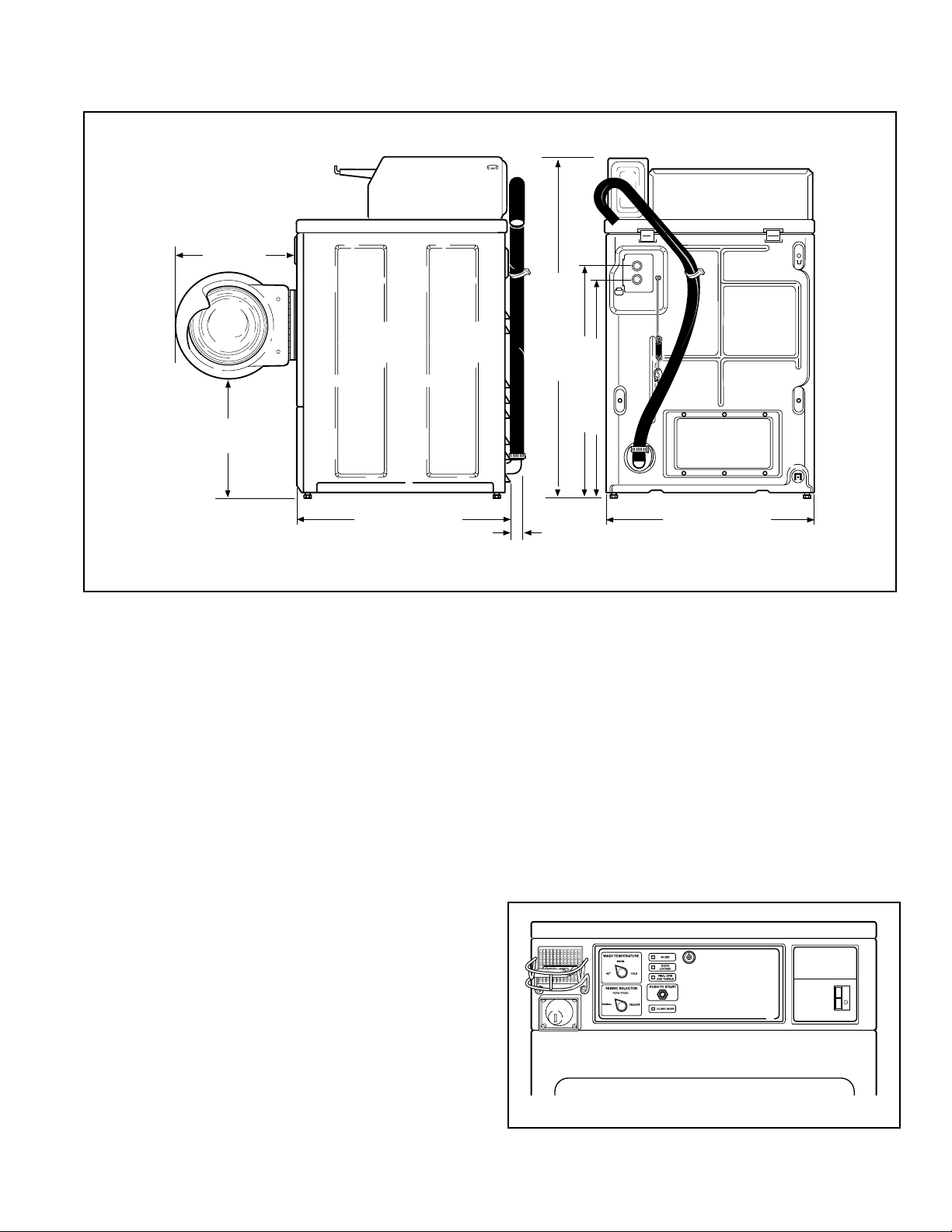
Dimensions and Specifications . . .
17.5"
(44.8 cm)
43" (109.2 cm)
31.1" (79 cm)
14.3"
(36.3 cm)
29.6" (75.1 cm)
28" (71.1 cm)
Additional Security . . .
T orx security screws are available (as optional equipment
at extra cost) for securing lower access pa nel to washer.
Order part number 62853.
A Torx bit, part number 282P4, is available (as optional
equipment at extra cost) for installing the Torx security
screws.
Coin Slide Guards . . .
(Coin Slide Models Only)
Using serrated hex head screws from accessories bag,
install coin slide guard to front of control cabinet. See
illustration.
A special sec urity screw kit is available (as optional
equipment at e xtra c ost) for securi ng the coin sl ide guar d
and front panel to front of washer. Order Security Kit
No. 298P3. A special driver, part number 56217, is
available (as optional equipment at extra cost) for
installing the special security screws.
2"
(5.1 cm)
26.9" (68.3 cm)
H270IE3a
A Torx bit holder, part number 24161, is available (as
optional equipment at extr a cost) to b e used with the T orx
bit.
OPERATING INSTRUCTIONS
Select Wash Temperature
685557
1.
HOT, WARM, COLD.
2.
Select Fabric Type
NORMAL, PERM PRESS, DELICATE.
3.
Load Supply Dispenser (See Instructions Below).
4.
Load Clothes.
5.
Insert Coin(s) / Card.
6.
To Start Washer-Close Door and Push Start.
DISPENSER INSTRUCTIONS
3
Open Dispenser Door.
1.
Load Supplies in Proper
2.
Compartment (as Indicated).
Close Dispenser Door.
3.
2
Detergent
1.
Liquid Bleach
2.
Fabric Softener
3.
1
685942
PERMANENT PRESS ALL FABRIC
NOTE: Coin slides and coin drawers are shown for
H174I
illustration only. You must obtain them locally.
685945 5
Page 8
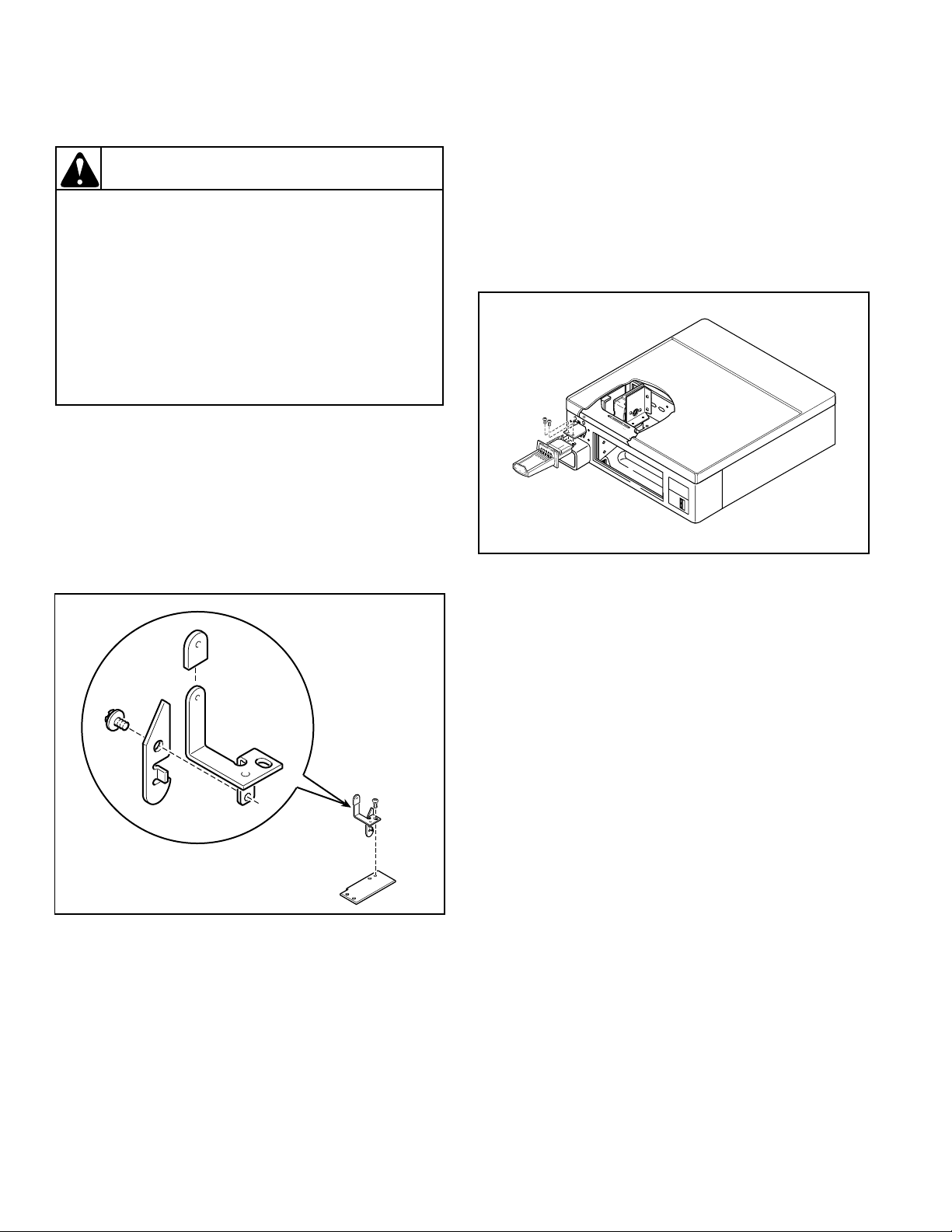
Washer Slide Extension . . .
H067I
(Coin Slide Models Only)
WARNING
To reduce the risk of electric shock, fire,
explosion, serious injury or death:
• Disconnect electric power to the washer
before servicing.
• Never start the washer with any guards/
panels removed.
• Whenever ground wires are removed
during servicing, these ground wires must
be reconnected to ensure that the washer
is properly grounded.
W003
Remove slide extension, shoulder screw, plastic boot,
actuator, actuator support, screws and lockwashers from
the accessories bag. Install slide extension as follows:
1. Unlock and open service door. Remove locking rod
holding coin slide to front of security cabinet.
NOTE: Refer to following illustration for Steps 2
through 4 .
5. Install assembed slide extension through coin slide
opening of security cabinet by reaching through
service door opening.
6. Assemble slide extension (No. 685593) to top side
of coin slide using two screws and lockwashers
(No. 03950), and tighten firmly. See illustration
below.
H068I
7. Reinstall assembled coin slide in security cabinet.
Close and lock service door.
2. Assemble plastic boot (No. 36165) onto actuator
support (No. 685592).
3. Assemble actuator (No. 36164) to actuator support
(No. 685592) using shoulder screw (No. 36166).
4. Place actuator and support assembly onto slide
extension, and install screw and lockwasher (No.
03950).
After slide extension has been installed, check washer
operation as follows:
1. Connect electrical power to washer.
NOTE: To determine if slide functions properly,
allow washer to complete its cycle, and for timer to
stop, before starting evaluation process .
2. Place required number of coins in slide. Push slide in
slowly and listen for coins to drop into coin drawer.
3. Push slide in a little farther and observe through
service door opening that actuator drops beyond
timer clutch. Continue pushing slide all the way in
and pull back. Confirm that the actuator will rotate
timer clutch and wash cycle starts.
NOTE: Washer will not start until Push-to-Start has
been pressed.
6 685945
Page 9
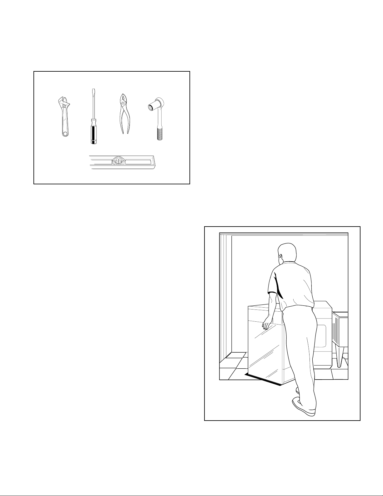
Before You Start . . .
Tools
For most installations, the basic tools you will need are:
WRENCH
SCREWDRIVER
PLIERS
LEVEL
SOCKET
WRENCH
9
/
1
6
"
D074IE1H
Installing the Washer . . .
Step 1:
Electrical Requirements
Refer to serial plate for specific electrical requirements.
For more detailed informatio n, refer to section on
Electrical Requirements.
Water Supply Requirements
Washer needs two standard 3/4 inch (19.1 mm) water
supply faucets with a pressure between 20-120 pounds
per square inch (138 to 827 kPa). For more detailed
information, refer to section on Water Supply
Requirements.
Position Washer Near Installation
Area
Move washer so that it is within four feet of the desired
area of installation.
H054IE1A
685945 7
Page 10

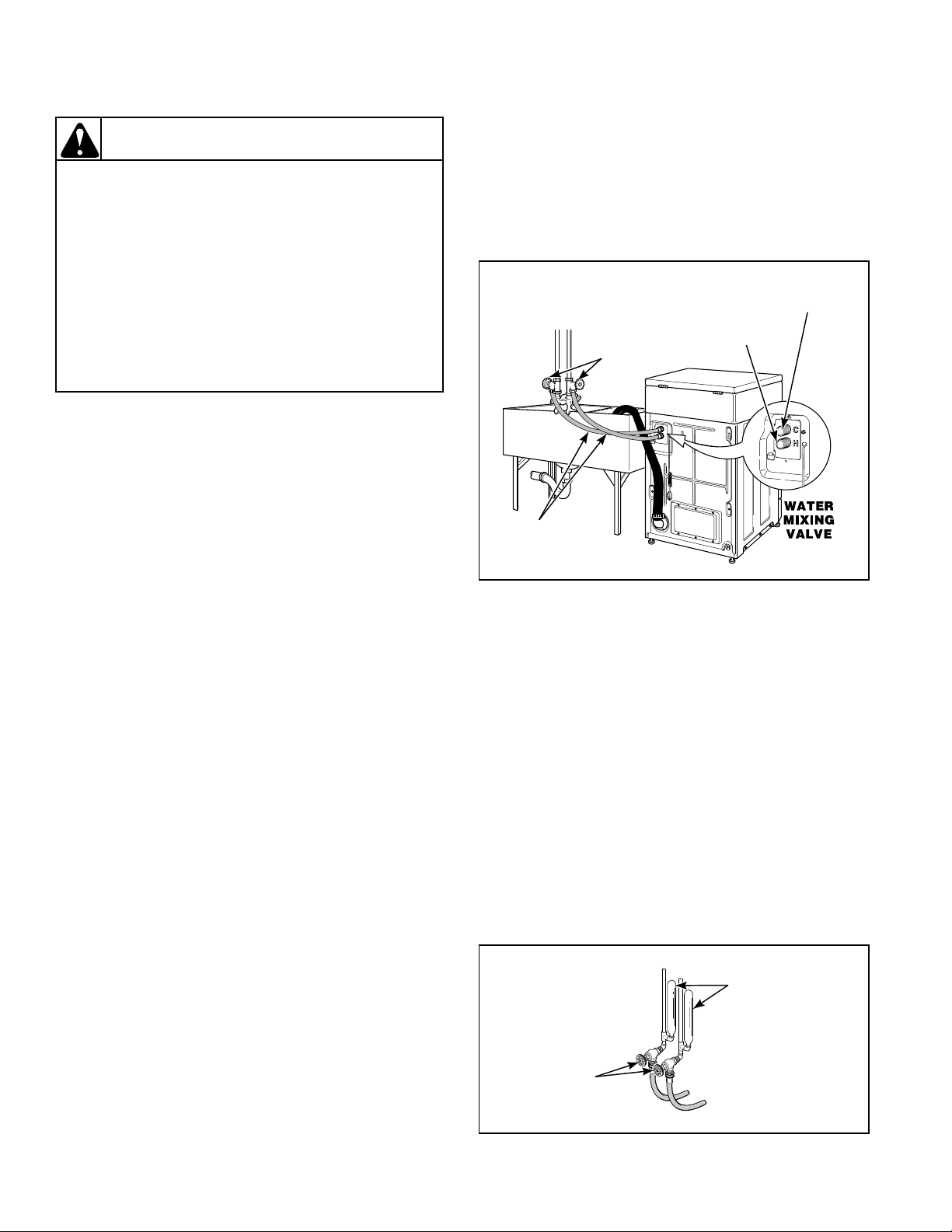
Step 2:
Connect Water Inlet Hoses
NOTE: Refer to section on Water Supply
Requirements before connectin g water inlet h oses.
Remove the four plain rubber washers from accessories
bag, and install them according to the illustra tion.
Turn on the water supply faucets and flush the lines for
approximately two minutes to remove any foreign
materials that co uld cl og the screens in the w at er mi xing
valve.
NOTE: When installing in newly constructed or
renovated building, it is very important to flush the
lines since build-up may have occurred during
construction.
IMPORTANT: Thread hose couplings onto valve
connections finger-ti ght, then approximat ely 1/4 turn
with pliers. DO NOT cross thread or overtighten
couplings.
RUBBER WASHER
(Plain)
INSTALL THIS
END OF HOSE
TO WATER
SUPPLY FAUCET
WATER SUPPLY
RUBBER WASHER
(Plain)
INLET
HOSE
INSTALL THIS END OF HOSE
TO VALVE CONNECTIONS
AT REAR OF WASHER
H091IE1A
COLD WATER
CONNECTION
HOT WATER
CONNECTION
FAUCETS
Turn water on and check for leaks. If leaks are found,
retighten the hose couplings. Continue tightening and
rechecking until no leaks are found.
WATER INLET
HOSES
H100IE1A
8 685945
Page 11
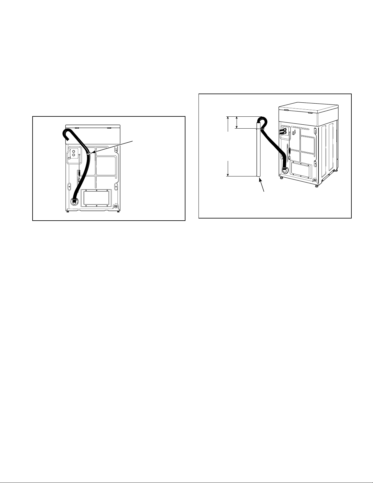
Step 3:
Connect Drain Hose to Drain
Receptacle
Remove the drain hose from its shipping position on the
rear of the washer by unhooking the hose from the
retainer clam p.
IMPORTANT: Drain receptacle must be capable of
handling a minimum of 1-3/8 inch (35 cm) outside
diameter drain hose.
RETAINER
CLAMP
H101IE1A
Standpipe Installatio n:
Place the drain hose into the standpipe.
Remove the beaded tie-down strap from accessories bag
and place around standpipe and drain hose and tighten
strap to hold hose to standpipe. This will pre vent the drai n
hose from dislodging from drain receptacle during use.
24" to 36"
(61 to 91.44 cm)
Recommended
Height
STANDPIPE
2" (5.08 cm) or 1-1/2" (4 cm)
H102IE1A
685945 9
Page 12

Step 4:
H027IE1B
HOOKED
END OF
SHIPPING
BRACE
BOLTS
SHOCK SLEEVES
MOTOR
MOUNT
WASHERS
Step 5:
Remove the Shock Sleeves and
Shipping Brace
Remove front access panel by removing the two screws.
Remove bolts and washers from shipping brace with
9/16" wrench and remove brace. Remove shock sleeves
by pulling on the yellow rope. Remove label from front
side of front access panel and place on backside of front
access panel.
NOTE: The shipping brace, bolts, was hers and shoc k
sleeves should be saved and MUST be reinstalled
whenever th e washer is moved more than four fe et.
Do not lift or transport washer from front or without
shipping materials installed.
Store the shipping materials in the bag provided in the
Accessories Bag. Save materials for use whenever the
washer is moved.
Reinstall front access panel.
Position and Level the Washer
Place washer in po si ti on on a clean, firm and re aso nabl y
level fl oor . Instal ling the was her on any type of carpeting
is not recommended.
Loosen 9/16" locknuts and adjust the leveling legs until
the washer does not rock.
NOTE: Level must rest on raised portion of top panel.
See illustration.
Tighten the locknut s securely agai nst the washer base
using the 9/16" wrench. If the locknuts are
not tight, washer will move out of position during
operation.
CAUTION
DO NOT slide washer across floor if the
leveling legs have been extended, as legs
and base could become damaged.
W248
NOTE: The shipping materials MUST be reinstalled
whenever the washer is moved. Refer to Moving
Washer to a New Location section for instructions.
CAUTION
Use of the dispenser drawer or washer door
as a handle in the transportation of the
washer may cause damage to the dispenser
or door.
Remove rubbe r feet from accessor ies bag and place on a ll
four leveling legs.
WASHER
BASE
LEVELING
LEG
RUBBER
CUP
LOCKNUT
LEVEL
H221IE1A
W185
OPERATING INSTRUCTIO
Select Wash Temperature
1.
Select Fabric Type
2.
Load Supply Dispenser (See
3.
Insert Coin(s) / Card.
5.
DISPENSER INSTRUCTION
Open Dispenser
1.
Compartment (as
2
Close Dispenser
3
7
5
5
5
8
6
3
1
2
Detergent
1.
685942
Detergent
2.
10 685945
Page 13

Step 6:
Step 7:
Wipe Out Inside of Wash Drum
Before using wash er for the f irst t ime, use a n all-pur pose
cleaner, or a detergent and water solution, and a damp
cloth to remove shipping dust from inside wash drum.
OPERATING INSTRUCTIO
Select Wash Temperature
1.
Select Fabric Type
2.
Load Supply Dispenser (See
3.
Insert Coin(s) / Card.
3
5.
1
2
DISPENSER INSTRUCTION
Open Dispenser
1.
Detergent
1.
Compartment (as
685942
2
Detergent
2.
Close Dispenser
3
685557
H266I
Plug in the Washer
Refer to secti on on Electr ical Requirements an d plug the
washer in.
D254I
Step 8:
Check Installation
Refer to Installer Check on the back cover of this manua l
and make sure that washer is installed correctly.
685945 11
Page 14

Moving Washer to a New Location . . .
R
T
To prevent damage while moving the washer, the
shipping materials MUST be reinstalled.
Reinstallation of Shipping
Materials
Remove front access panel by removing two screws.
Place the shock sleeves on all four shock absorbers. See
illustration.
Insert hooked end of shipping br ace into the open sl ot of
the motor mount. Attach with bolts and washers. See
illustration.
Reinstall front access panel.
HOOKED
END OF
SHIPPING
BRACE
BOLTS
Refer to Installing Your Washer section for proper
procedures whenever the washer is moved.
SHOCK SLEEVES
MOTO
MOUN
12 685945
Page 15
Electrical Requirements . . .
(120 Volt, 60 Hertz with 3-Prong Grounding Plug)
NOTE: The wiring diagram is located in the control
cabinet.
WARNING
WARNING
To reduce the risk of fire, electric shock,
serious injury or death, all wiring and
grounding MUST conform with the latest
edition of the National Electrical Code, ANSI/
NFPA No. 70, and such local regulations as
might apply. It is the customer’s
responsibility to have the wiring and fuses
checked by a qualified electrician to make
sure the laundry room has adequate
electrical power to operate the washer.
DO NOT OVERLOAD CIRCUITS
DO NOT USE ADAPTER
DO NOT USE AN EXTENSION CORD
D009IE1A
W227
Improper connection of the equipmentgrounding conductor can result in a risk of
electric shock. Check with a qualified
electrician or serviceman if you are in doubt
as to whether the washer is properly
grounded.
W216
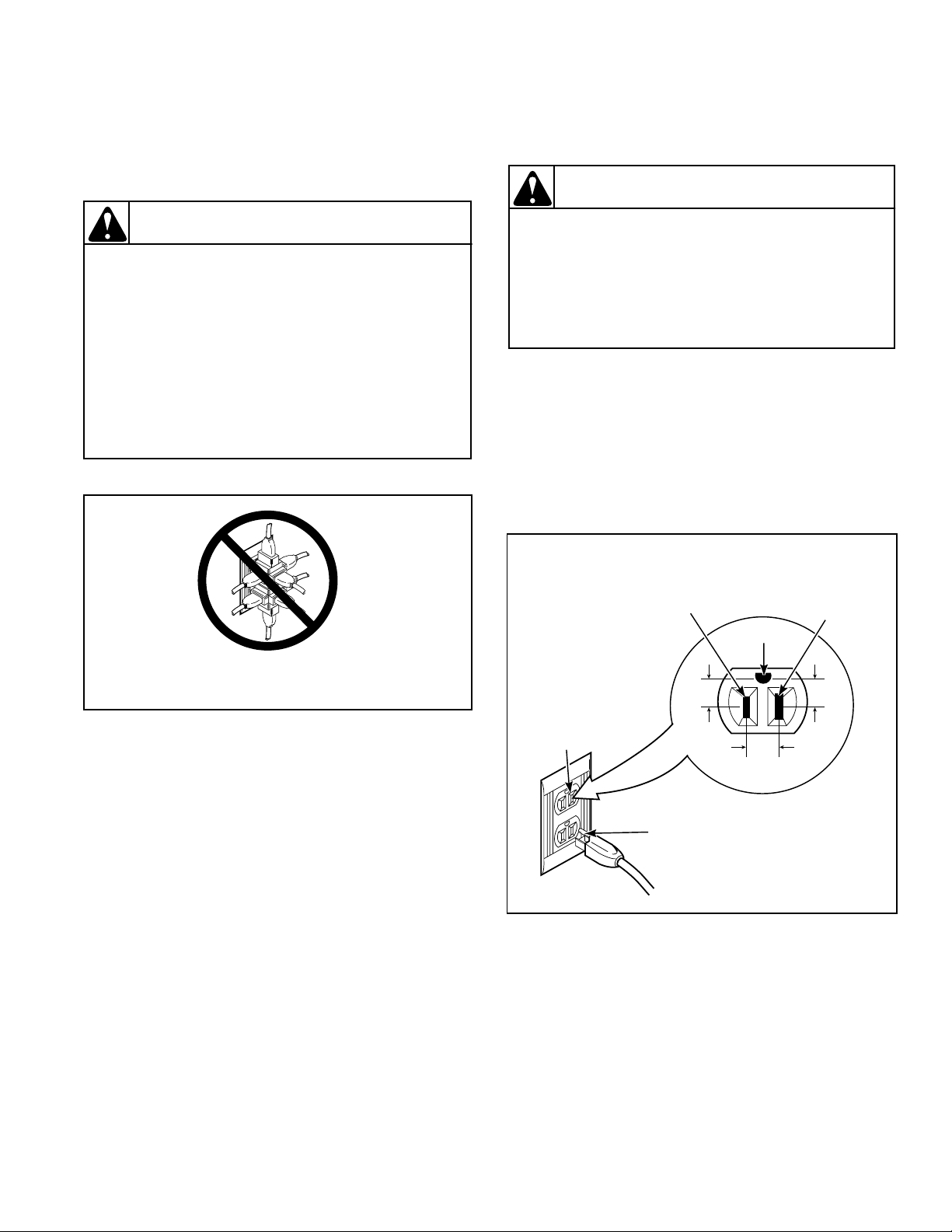
Do not modify the plug pr ov ide d with th e w asher — if i t
will not fit the outlet, have a proper outlet installed by a
qualified electrician.
NOTE: Have a qualified electrician check the polarity
of the wall receptacle. If a voltage reading is measured
other than that illustrated, the qualified electrician
should correct the problem.
STANDARD 120 VOLT, 60 HERTZ,
3-WIRE EFFECTIVELY GROUNDED CIRCUIT
L1
120 ± 12
V.A.C.
GROUND
NEUTRAL
SIDE
0
V.A.C.
Grounding Instructions
The washer must be grounded. In the event of
NEUTRAL
120 ± 12
V.A.C.
malfunction or breakdown, grounding will reduce the
risk of electric shock by providing a path of least
resistance for electric current. The washer is equipped
with a cord having an equipment-grounding conductor
ROUND
GROUNDING
PRONG
and a 3-prong groundi ng plug. The pl ug must be pl ugged
into an appropriate outlet that is properly installed and
grounded in accordance with all local codes and
D090IE1A
ordinances.
685945 13
Page 16
Water Supply Requirements . . .
WARNING
Under certain conditions, hydrogen gas may
be produced in a hot water system that has
not been used for two weeks or more.
HYDROGEN GAS IS EXPLOSIVE. If the hot
water system has not been used for such a
period and before using the washer, turn on
all hot water faucets and let the water flow
from each for several minutes. This will
release any accumulated hydrogen gas. The
gas is flammable. Do not smoke or use an
open flame during this time.
W029
NOTE: Water supply faucets must fit standard
3/4 inch (19.1 mm) female gar den hose coupl ings. DO
NOT USE SLIP-ON OR CLAMP-ON
CONNECTIONS.
NOTE: Water supply faucets should be readily
accessible to permit turning them off when washer is
not being used.
NOTE: Longer inlet hoses are available (as optional
equipment at extra cost) if the hoses (supplied with
the washer) are not long enough for the installation.
Order hoses as follows:
No. 20617 Inlet Hose (8 foot) (2.44m)
No. 20618 Inlet Hose (10 foot) (3.05m)
COLD WATER
CONNECTION
HOT WATER
WATER SUPPLY
FAUCETS
WATER INLET
HOSES
CONNECTION
H100IE1A
Water Temperature
Cold:
Recommended cold water temperature is 60° to 80°
Fahrenheit, 16° to 27° Celsius.
Hot:
Recommended hot water temperature is 120° to 140°
Fahrenheit, 49° to 60° Celsius.
Warm:
Mixture of hot and cold water. (Warm wat er temperature
is dependent upon the wat er temperature and the pre ssure
of both the hot and cold water supply lines.)
IMPORTANT: Turn off water supply faucets after
check-out and demonstration. Owner should t urn off
water supply whenever there will be an extended
period of non-use.
Water Pressure
Pressure must be a minimum of 2 0 to a maximum of 1 20
pounds per square inch (138 to 827 kPa) static pressure
measured at the faucet.
NOTE: Water pressure under 20 pounds per square
inch (138 kPa ) will cause an extended fill time in the
washer and may not properly flu sh out the detergent
dispenser.
Risers
Risers (or air cushions) may have to be installed if the
pipes knock or pound when flow of water stops. The
risers are more efficient when installed as close as
possible to the water supply faucets (see illustra tion
below).
RISERS
(Air cushions)
WATER SUPPLY
FAUCETS
W005IE1C
14 685945
Page 17

Operation Instructions for
Electromechanical Washers . . .
IMPORTANT: Prior to first wash, use an all-purpose
cleaner, or a detergent and water solution, and a
damp cloth to remove shipping dust from inside of
washtub.
Step 1:
Load Laundry
Load items loosely into wash drum.
OPERATING INSTRUCTIONS
Select Wash Temperature
685557
1.
HOT, WARM, COLD.
2.
Select Fabric Type
NORMAL, PERM PRESS, DELICATE.
3.
Load Supply Dispenser (See Instructions Below).
4.
Load Clothes.
5.
Insert Coin(s) / Card.
6.
To Start Washer-Close Door and Push Start.
DISPENSER INSTRUCTIONS
Open Dispenser Door.
1.
Load Supplies in Proper
2.
Compartment (as Indicated).
Close Dispenser Door.
3.
3
1
2
Detergent
1.
Liquid Bleach
2.
Fabric Softener
3.
685942
PERMANENT PRESS ALL FABRIC
Step 3:
Add Laundry Supplies
Open dispenser drawer. Measure and add low sudsing
detergent (1 ), bleach (2) and fabric softener (3) to the
dispenser drawer (see illustration). Close dispenser
drawer.
IMPORTANT: If using detergents made for topload
washers, avoid oversudsing by using 1/2 of the
recommended amount.
CAUTION
Dispenser drawer requires a special tool for
removal. Contact a service person if removal
is necessary.
W236
3
H237I
Step 2:
Close Loading Door
Close the loading door tightly. The washer will not
operate with the loading door open.
OPERATING INSTRUCTIO
Select Wash Temperature
1.
Select Fabric Type
2.
Load Supply Dispenser (See
3.
Insert Coin(s) / Card.
3
5.
1
2
DISPENSER INSTRUCTION
Open Dispenser
1.
Detergent
1.
Compartment (as
685942
2
Detergent
2.
Close Dispenser
3
685557
1
2
OPERATING INSTRUCTIO
Select Wash Temperature
1.
Select Fabric Type
2.
Load Supply Dispenser (See
3.
Insert Coin(s) / Card.
3
5.
1
2
DISPENSER INSTRUCTION
Open Dispenser
1.
Detergent
1.
Compartment (as
685942
2
Detergent
2.
Close Dispenser
3
685557
H220I
H238I
685945 15
Page 18

Step 4:
HOT COLD
WARM
WASH TEMPERATURE
CPW158A
D363I
Indicator Lights
Set WASH/RINSE Temperatures
Set at HOT (COLD rinse), WARM (COLD rinse) or
COLD (COLD rinse).
NOTE: Always follow Manufacturer’s care labels.
Step 5:
Select Fabric Selector
Set regular loads at NORMAL or PERM PRESS. Set
delicate loads at DELICATE.
FABRIC SELECTOR
PERM PRESS
NORMAL DELICATE
CPW158B
IN USE Light:
This light will remain on while washer is in use.
DOOR LOCKED Light:
This light will come on afte r the start button has been
pushed and the w asher door ha s lock ed. I t will remain on
until the was h cycle has ended.
FINAL SPIN AND TUMBLE Light:
This light will come on at the start of the final spin and
remain on until the wash cycle has ended.
CLOSE DOOR Light:
This light will come on if door is not closed tightly.
Firmly push door until light goes out.
IMPORTANT: If washer fails to operate properly
after installation, make sure electrical service and
water supply faucets are turned on. Are all the
controls properly set? Have a qualified service person
refer to the wiring diagram (located inside of washer
cabinet), check for broken, loose or incorrect wiring.
W ARNING
To reduce the risk of bodily injury, do not
remove laundry from washer until all lights
are out, and all moving parts have stopped.
W092
The washer will stop (pau se) shor tly befor e the f i rst sp in
and final spin.
Step 6:
Insert Money
Place coin(s) in slide and carefully push in as far as
possible and then pull slide out as far as possible. After
IN USE
the PUSH-TO-START button.
light comes on (indicating start of cycle), press
16 685945
Page 19

Operation Instructions for
Electronic Control Washers
IMPORTANT: Prior to first was h, use an all-purpose
cleaner, or a detergent and water solution, and a damp
cloth to remove shipping dust fro m inside of washtub.
Step 1:
Load Laundry
Load items loosely into wash drum.
OPERATING INSTRUCTIONS
Select Wash Temperature
1.
HOT, WARM, COLD.
Select Fabric Type
2.
NORMAL, PERM PRESS, DELICATE.
Load Supply Dispenser (See Instructions Below).
3.
Load Clothes.
4.
Insert Coin(s) / Card.
5.
To Start Washer-Close Door and Push Start.
6.
505617
DISPENSER INSTRUCTIONS
Open Dispenser Door.
1.
Load Supplies in Proper
2.
Compartment (as Indicated).
Close Dispenser Door.
3.
3
1
2
Detergent
1.
Liquid Bleach
2.
Fabric Softener
3.
685942
FABRICS AND TEMPERATURES
PERM
NORMAL
PRESS
WARM
HOT
WASHER
DOOR
TO START
LOCKED
DELICATES
COLD
PUSH CYCLE PAD
BY FLASHING LIGHT
Step 3:
Add Laundry Supplies
Open dispenser drawer. Measure and add low sudsing
detergent (1), bleach (2) and fabric softener (3) to the
dispenser drawer (see illustration). Close dispenser
drawer.
IMPORTANT: If using detergents made for topload
washers, avoid oversudsing by using 1/2 of the
recommended amount.
CAUTION
Dispenser drawer requires a special tool for
removal. Contact a service person if removal
is necessary.
W236
3
H239I
Step 2:
Close Loading Door
Close loading door tightly. The washer will not operate
with the loading door open.
perature
LD.
, CO
ash Tem
ARM
PRESS, DELICATE.
OPERATING INSTRUCTIONS
T, W
Select W
1.
AL, PERM
HO
RM
Select Fabric Type
2.
NO
Load Supply Dispenser (See Instructions Below).
3.
asher-Close Door and Push Start.
Load Clothes.
4.
3
Insert Coin(s) / Card.
5.
To Start W
6.
1
2
DISPENSER INSTRUCTIONS
pen Dispenser Door.
ent (as Indicated).
O
Detergent
1.
1.
Load Supplies in Proper
partm
Liquid Bleach
685942
2.
2.
Com
Fabric Softener
3.
Close Dispenser Door.
3.
WASHER
DOOR
LOCKED
TO START
PUSH CYCLE PAD
DELICATES
BY FLASHING LIGHT
PERM
COLD
PRESS
WARM
NORMAL
HOT
1
2
OPERATING INSTRUCTIO
Select Wash Temperature
1.
Select Fabric Type
2.
Load Supply Dispenser (See
3.
Insert Coin(s) / Card.
3
5.
1
2
DISPENSER INSTRUCTION
Open Dispenser
1.
Detergent
1.
Compartment (as
685942
2
Detergent
2.
Close Dispenser
3
685557
H276I
H240I
685945 17
Page 20

Step 4:
Step 6:
Set Fabric Selector
Push touchpad for NORMAL, PERM PRESS or
DELICATES cycles. Light indicates selection.
NOTE: Changes can be made to Fabric Selector
setting up until the first fill is complete.
FABRICS AND TEMPERATURES
NORMAL
HOT
PERM
PRESS
WARM
DELICATES
COLD
H142I
Step 5:
Set Wash Temperature
Insert Coin(s) or Card
To Insert Money:
Check pricing as seen on digital display.
W387I
To Insert Card:
Insert card into opening. Follow directions on display.
DO NOT REMOVE THE CARD UN TIL DISPLAY
READS “Remove Card.”
Push touchpad for HOT, WARM or COLD. Light
indicates selection.
NOTE: Always follow Manufacturer’s care labels.
FABRICS AND TEMPERATURES
NORMAL
HOT
PERM
PRESS
WARM
DELICATES
COLD
H143I
M330I
Step 7:
Start Washer
After vend price has been satisfied, the selected cycle pad
will flash.
Push flashi ng cycle pad to start washer. DOOR MUST
BE CLOSED TO START WASHER.
FABRICS AND TEMPERATURES
NORMAL
HOT
PERM
PRESS
WARM
DELICATES
COLD
H142I
18 685945
Page 21

Indicator Lights
WASH:
WASH is lit at the beginning of a Wash cycle and will
remain lit until the wash cycle is complete.
RINSE:
RINSE is lit at the beginning of the Rinse or Extra Rinse
cycle and will remain lit until the cycle is complete.
SOAK:
SOAK is lit at the be ginning o f the Wash Pause cyc le, and
the display will light “WASH SOAK.”
SPIN:
SPIN is lit for all Spin cycles. During a Rinse or Extra
Rinse Spin Cycle, the display will light “RINSE SPIN”.
At the beginning of Final Spin, the display will light
“Spin.”
PRICE:
PRICE is lit to indicate that value displayed is the vend
price remaining to be satisfied. Once th e vend price is
satisfied, the word “PRICE” will go off.
TIME REMAINING:
TIME REMAINING is lit to indicate that the number
displayed by two digits and the colon is the time
remaining in the current cycle. It will light at the start of
the cycle and remain lit until the cycle is completed.
INSERT COINS:
INSERT COINS is lit to prompt the user to insert coins or
card to satisfy the vend price. When INSERT COINS is
lit, the three digits and decimal point show the vend price
remaining to be satisfied.
UNBALANCE:
UNBALANCE is lit and will flash after the cycle is
complete when the washer fails to spin due to an
unbalanced load.
IMPORTANT: If washer fails to operate properly
after installation, make sure electrical service and
water supply faucets are turned on. Are all the
controls properly set? Have a qualified serviceman
refer to the wiring diagram (located inside of washer
control hood), check for broken, loose or incorrect
wiring.
W ARNING
To reduce the risk of bodily injury, do not
remove laundry from washer until all lights
are out, and all moving parts have stopped.
W092
WASHER DOOR LOCKED:
WASHER DOOR LOCKED is lit whenever the door is
locked. The door cannot be opened when this light is on.
685945 19
Page 22

Maintenance . . .
Cold Weather Care
If the washer is de li ver ed on a cold d ay (belo w fre ezing),
or is stored in an unheated room or area during the cold
months, do not attempt to operate it until the washer has
had a chance to warm up.
Care Of Your Washer
Use only a damp or sudsy cloth for cleaning the control
panel. Some cleaning product spra ys may harm the finish
on the control panel or damage the interior of the hood.
Wipe the washer cabinet as needed. If detergent, bleach
or other washing p roducts are spilled on the cabinet, wip e
immediately. Some products will cause permanent
damage if spilled on the cabinet.
Do not use scouring pads or abrasive cleansers.
Do not lay sharp or rough objects on or against the
washer. The finish could be damaged.
The wash drum and win dow will need no pa rt ic ula r c ar e
although they may need rinsing or wiping after an
unusual load has been wash ed. Outside of window can be
cleaned with household window cleaner.
Vacations and Extended
Non-Use
IMPORTANT: To avoid possible property damage
due to flooding, turn off the water supply to the
washer whenever there will be an extended period of
non-use.
20 685945
Page 23

Before You Call For Service . . .
If the Washer:
You may save time and money by checking the following:
Won’t
Fill
• • • • Close the loading door tightly.
• • • • Check the laundry room fuse or circuit
• Turn on the hot and cold water faucets.
• Clean the screens in the water mixing valve.
Won’t
Start
• Be sure power cord is plugged all the way
Won’t
Tumble
• • Are controls properly set?
• • Broken drive belt. Call the service person.
Won’t
Spin
• • Foreign object trap clogged. Call service
Won’t
Drain
Possible Reason —
Do This To Correct
into the electrical outlet.
breaker.
person.
685945 21
Page 24

Information for Handy Reference . . .
Alliance Laundry Systems LLC
Shepard Street
P.O. Box 990
Ripon, Wisconsin 54971-0990
Date Purchased _________________________________________________________________________________
Model Number _________________________________________________________________________________
Serial Number __________________________________________________________________________________
Dealer’s Name __________________________________________________________________________________
Dealer’s Address ________________________________________________________________________________
Dealer’s Phone Number (______) ___________________________________________ _____ ____ _____ ____ _____
Service Agency _________________________________________________________________________________
Service Agency Address __________________________________________________________________________
Service Phone Number (______) ___________________________________________________________________
Record this information and keep your sales slip. Model and serial numbers are located on the nameplate.
22 685945
Page 25

Carga frontal
con contador de
monedas
De lavadoras comerciales
Instalación y operación
OPERATING INSTRUCTIO
Select Wash Temperature
1.
Select Fabric Type
2.
Load Supply Dispenser (See
3.
Insert Coin(s) / Card.
3
5.
1
2
DISPENSER INSTRUCTION
Open Dispenser
1.
Detergent
1.
Compartment (as
685942
2
Detergent
2.
Close Dispenser
3
685557
H236I
No. de Pieza 685945R5
Octobre 1999
Page 26

GUARDE ESTAS INSTRUCCIONES PARA REFERENCIA EN EL FUTURO. (Si la lavadora
cambia de dueño, asegúrese de que este manual vaya con la misma).
ADVERTENCIA
Por su propia seguridad y para reducir el
riesgo de incendio o explosión no
almacene ni use gasolina u otro s vapores y
líquidos inflamables cerca de éste o
cualquier otro aparato electrodoméstico.
W022S
© Derechos reservados 1999, Alliance Laundry Systems LLC
Reservados todos los derechos. Ninguna sección del presente manual puede ser reproducida o transmitida en forma
alguna o a través de ningún medio sin el expreso consentimiento por escrito del editor.
24 685945 (SP)
Page 27

Índice
Piezas de repuesto.................................................................................... 25
Instrucciones de seguridad importantes ...............................................26
Dimensiones y especificaciones ..............................................................28
Seguridad adicional................................................................................. 28
Protector del tragamonedas .................................................................. 28
Extensión del tragamonedas de la lavadora ....................... ..................29
Antes de comenzar .................................................................................. 30
Instalación de la lavadora
Paso 1: Coloque la lavadora cerca del área de instalación .................30
Paso 2: Conecte las mangueras de suministro de agua.......................31
Paso 3: Conexión de la manguera de desagüe en el
receptáculo de desagüe...................................................................32
Paso 4: Saque los manguitos de amortiguador y el tirante
sujetador ......................................................................................... 33
Paso 5: Coloque la lavadora en su lugar y nivélela............................ 33
Paso 6: Limpie el interior del tambor de la lavadora..........................34
Paso 7: Enchufe la lavadora ...............................................................34
Paso 8: Verifique la instalación.......................................................... 34
Desplazamiento de la lavadora a un nuevo sitio...................................35
Requisitos eléctricos .............................................................................. .. 36
Requisitos de suministro de agua........................................................... 37
Instrucciones de operación de lavadoras electromecánicas
Paso 1: Cargue la lavadora ................................................................. 39
Paso 2: Cierre la compuerta de carga.................................................39
Paso 3: Agregue los suministros para lavar ....................................... 39
Paso 4: Seleccione las temperaturas de lavado y enjuague
WASH/RINSE ............................................................................... 40
Paso 5: Ajuste el selector de tela ....................................................... 40
Paso 6: Deposite la(s) moneda(s) ...................................................... 40
Luces indicadoras .............................................................................. 41
Instrucciones para la operación de lavadoras con control electrónico
Paso 1: Cargue la lavadora ................................................................. 42
Paso 2: Cierre la compuerta de carga.................................................42
Paso 3: Agregue los suministros para lavar ....................................... 43
Paso 4: Ajuste el selector de tela ....................................................... 43
Paso 5: Seleccione la temperatura de lavado ..................................... 43
Paso 6: Inserte la(s) moneda(s) o la tarjeta......................................... 44
Paso 7: Arranque la lavadora ............................................................. 44
Luces indicadoras .............................................................................. 45
Mantenimiento
Cuidados en climas fríos ...................................................................46
Cuidado de la lavadora ...................................................................... 46
Vacaciones y falta de uso de la lavadora durante un
período prolongado ........................................................................ 46
Antes de llamar al centro de servicio .................................................... 47
Información para una referencia a la mano ........................................ 48
Lista de comprobación del instalador ................................Tapa posterior
Piezas de repuesto
Si requiere piezas de repuesto, póngase en contacto con
establecimiento donde adquirió la máquina o a
685945 (SP) 25
Alliance Laundry Systems LLC
Shepard Street
P.O. Box 990
Ripon, WI 54971-0990
(920) 748-3950
para obtener el nombre y la dirección del distribuidor
autorizado de piezas de repuesto más cercano.
Page 28

INSTRUCCIONES DE SEGURIDAD
IMPORTANTES
(Guarde estas instrucciones)
ADVERTENCIA
Para reducir el riesgo de causar un incendio,
o de sufrir una descarga o sacudida
eléctrica, lesiones personales serias o la
muerte, al usar su lavadora cumpla con
estas precauciones básicas:
1. Lea todas las instru cciones an tes de utilizar la
lavadora.
2. Remítase a la sección de INSTRUCCIONES
DE CONEXIÓN A TIERRA del manual de
INSTALACIÓN para una correcta conexión a
tierra de su lavadora.
3. No lave prendas que s e hayan li mpiado, l avado,
sumergido o tratado con gasolina, solventes
para lavar al seco u otras sustancias
inflamables o explosivas, o que tengan rastros
de dichas sustancias. Estas sustancias despiden
gases que pueden encenderse o explotar.
4. No agregue gasolina, solventes para lavar al
seco u otras sustancias explosi vas o in flamable s
al agua que utilizará para el lavado. Estas
sustancias despiden vapores que pueden
encenderse o explotar.
W023S
8. No introduzca la mano en la lavadora si la tina
o el agitador está en movimiento.
9. No instale ni coloque la lavadora en un lugar
donde esté expuesta al agua o a la intemperie.
10. No manipule indebidamente los controles de la
lavadora.
11. No repare ni cambie ninguna pieza de la
lavadora, ni trate de repararla, salvo que las
instrucciones de mantenimi ento para el usuario
lo recomienden de manera expresa, o lo
indiquen las instrucciones de reparación del
usuario que usted está en capacidad de
entender y llevar a cabo.
12. Para reducir el riesgo de descarga eléctrica o
incendio, NO UTILICE extensiones ni
adaptadores para conectar la lavadora al
tomacorriente.
13. Utilice su lavadora sólo para la finalidad con la
que fue fabricada, es decir, para lavar ropa.
14. Desconecte SIEMPRE la lavadora del
tomacorriente antes de hacerle cualquier
mantenimiento. Desconecte el cable de
suministro de energía eléctrica sujetando el
tomacorriente en lugar de tirar del cable.
5. En ciertos casos, cu ando no s e u ti li za el si st ema
de agua caliente durante dos semanas o más,
puede almacenarse gas hidrógeno en dicho
sistema. EL GAS HIDRÓGENO ES
EXPLOSIVO. Si no ha utilizado el sistema de
agua caliente durante dos s emanas o más, ante s
de usar la lavadora o la combinación de
lavadora secadora, abra todos los grifos del
agua caliente y deje que el agua fluya por ellos
durante un tiempo. De est a mane ra, se liberará
todo el gas hidrógeno acumulado. Dicho gas es
inflamable. No fume ni utilice llama abierta
durante este lapso de tiempo.
6. No deje que los niños jueguen sobre o dent ro de
la lavadora. Debe supervisarse cuidados amente
a los niños cuando se utiliza la lavadora cerca
de ellos. Esta es una medida de seguridad para
todos los artefactos eléctricos.
7. Antes de sacar de servicio la lavadora o
desecharla, saque la tapa del compartimiento
de lavado.
26 685945 (SP)
15. Instale la lavadora siguiendo las
INSTRUCCIONES DE INSTALACIÓN.
Todas las conexiones de agua, desagüe,
suministro de energía eléctrica y tierra deben
cumplir con las normas establecidas en los
códigos locales y deben ser realizadas por
personal autorizado, cuando el caso lo amerite.
No realice las conexiones usted mismo a menos
que sepa cómo hacerlo.
16. Para reducir los riesgos de incendios, no debe
introducirse en la lavadora ropa c on ras tro s de
sustancias inflamables, como por ejemplo,
aceite vegetal, aceite de cocina, aceite para
lubricar máquinas, productos químicos
inflamables, diluyente de pinturas, etc., y
prendas que contengan cera s u otros producto s
químicos, tales como mopas y paños de
limpieza. Estas sustancias inflamables pueden
provocar que las telas se prendan en fuego.
Page 29

17. No utilice suavizadores de ropa o productos
para eliminar la estática, a menos que lo
recomiende el fabricante del suavizador o del
producto.
18. Conserve su lavadora en buen estado. Golpear
o dejar caer la lavadora puede dañar los
dispositivos de seguridad. Si esto ocurre, haga
revisar la lavadora con personal de
mantenimiento calificado.
19. Si el cordón de alimentación eléctrica está
dañado, deberá ser reemplazado por un co rdón
o conjunto especial, que puede adquirirse a
través del fabricante o du su agente de servicio.
20. Asegúrese de que las conexiones de agua tengan
una válvula de corte y que las conexio nes de las
mangueras de llenado estén bien apretadas.
CIERRE las válvulas de corte cuando termine
la jornada.
21. La compuerta de carga DEBERÁ ESTAR
CERRADA cuando la lavadora se es té llenando
o cuando esté funcionando el agi tador o el ciclo
de centrifugado. NO anule el seguro de la
compuerta de carga, permitiendo que la
lavadora funcione (lavado y centrifugado) con
la compuerta abierta.
23. Siga siempre las instrucciones para el cuidado
de la ropa suministradas por el fabricante de
las prendas de vestir.
24. Nunca ponga a funcionar la lavadora sin tener
todos los protectores o paneles colocados en su
posición.
25. NO ponga a funcionar la lavadora con piezas
dañadas o rotas.
26. NO anule ningún dispositivo de seguridad.
27. El incumplimiento de las instrucciones del
fabricante para la instalación, mantenimiento u
operación de la lavadora podría provocar
lesiones personales o daños a la propiedad.
NOTA: Las INSTRUCCIONES DE SEGURIDAD
IMPORTANTES y ADVERTENCIAS que se presentan en
este manual no pretenden contemplar todas las posibles
situaciones y condiciones que pudieran presentarse. La
instalación, mantenimiento y operación de la lavadora
deben realizarse con sentido común, precaución y cuidado.
Comuníquese siempre con el vendedor, distribuidor,
agente de servicios o fabr icant e cua ndo teng a probl emas
o se encuentre en una situación que no comprenda.
22. Lea y aplique siempre las instruccion es del
fabricante que se encu entran en los paque tes de
productos para la limpieza y lavado. Respete
las advertencias o precaucione s. Para reducir el
riesgo de envenenamiento o quemaduras con
productos químicos, mantenga en todo
momento dichos productos fuera del alcanc e de
los niños (guárdelos preferiblemente en un
gabinete con llave).
685945 (SP) 27
Page 30

Dimensiones y especificaciones . . .
5.1 cm
(2")
44.8 cm
(17.5")
110.7 cm (43.6")
79 cm (31.1")
36.3 cm
(14.3")
75.1 cm (29.6")
71.1 cm (28")
Seguridad adicional . . .
Como equipo opcional (a un costo adicional) se ofrecen
tornillos de seguridad Torx para asegurar el panel de
acceso inferior a la lavadora. Su número de pieza es
62853.
También se ofrece una broca Torx, número de pieza
282P4 (como equip o opcional a un costo adicional) para
instalar los tornillos de seguridad Torx.
Protector del tragamonedas . . .
(Solamente modelos con tragamonedas)
Utilizando los tornillos estriados de cabeza hexagonal
incluidos en la bolsa de accesorios , instale el prote ctor del
tragamonedas en la parte delantero del gabinete de
control. Vea la ilustración.
Se ofrece un juego especial de seguridad (como equipo
opcional a un costo adicional) para fijar el protector de
tragamonedas y el panel fron tal a la pa rte del anter a de la
lavadora. El número de pieza del juego de seguridad es
298P3. También se ofrece un destornillador especial,
número de pieza 56217 (co mo equipo opcional a un costo
adicional), para instalar los tornillos especiales de
seguridad.
NOTA: Los tragamonedas y depósit os de mone das se
muestran para fines de orientación únicamente. Los
mismos deberán adquirirse localmente.
5.1 cm
(2")
68.3 cm (26.9")
H269IS3A
Adicionalmente, está disponible un portabrocas Torx,
número de pieza 24161 (como equip o opcional a un costo
adicional) para utilizarse con la broca Torx.
OPERATING INSTRUCTIONS
Select Wash Temperature
685557
1.
HOT, WARM, COLD.
2.
Select Fabric Type
NORMAL, PERM PRESS, DELICATE.
3.
Load Supply Dispenser (See Instructions Below).
4.
Load Clothes.
5.
Insert Coin(s) / Card.
6.
To Start Washer-Close Door and Push Start.
DISPENSER INSTRUCTIONS
3
Open Dispenser Door.
1.
Load Supplies in Proper
2.
Compartment (as Indicated).
3.
Close Dispenser Door.
2
Detergent
1.
Liquid Bleach
2.
Fabric Softener
3.
1
685942
H174I
PERMANENT PRESS ALL FABRIC
28 685945 (SP)
Page 31

Extensión del tragamonedas
de la lavadora
(Solamente modelos con tragamonedas)
ADVERTENCIA
Para reducir el riesgo de descarga eléctrica,
incendio, explosión, lesiones graves o
letales:
• Desconecte la energía eléctrica a la
lavadora antes de darle mantenimiento.
• Nunca arranque la lavadora sin los
paneles y protectores colocados.
• Cuando se desconecten los conductores
de tierra durante el mantenimiento, los
mismos deberán volver a conectarse para
asegurar que la lavadora quede
debidamente conectada a tierra.
Saque la extensión del traga monedas, tornillos con
reborde, bota plástica, actuador, soporte del actuador,
tornillos y arandelas de seguridad de la bolsa de
accesorios. Instale la extensión del tragamonedas como
se describe a continuación:
W003SA
4. Coloque el actuador y el montaje de s oporte sobre la
extensión del tragamonedas e instale el tornillo y la
arandela de seguridad (Nº 03950).
5. Instale la extensión del tragamonedas armada a
través de la abertura del tragamon edas del gabinete
de seguridad introduciendo la mano a través de la
abertura de la puerta de servicio.
6. Monte la extensión del tragamoneda s (Nº 685593) en
el lado superior del tragamonedas utilizando dos
tornillos y arandelas de seguridad (Nº 03950) y
apriete firmemente los tornillos. Vea la siguiente
ilustración.
1. Desbloquee y abra la puerta de servicio. Saque la
barra bloqueadora que sujeta el tragamonedas a la
parte delantera del gabinete de seguridad.
NOTA: Para ejecutar los pasos 2 al 4 consulte la ilus-
tración siguiente.
H067I
2. Monte la bota plástica (Nº 36165) en el soporte del
actuador (Nº 685592).
3. Monte el actuador (Nº 36164) en el soporte del
actuador (Nº 685592) utilizando los tornillos con
reborde (Nº 36166).
H068I
7. Reinstale el tragamonedas armado en el gabinete de
seguridad. Cierre y bloquee la puerta de servicio.
Una vez instalada la extensión del tragamonedas,
compruebe el funcionamiento de la lavador a de la forma
siguiente:
1. Conecte la energía eléctrica a la lavadora.
NOTA: Para comprobar que el tragamonedas funciona
correctamente, espere a que la la v adora complete el ciclo y
el temporizador se detenga antes de iniciar el proceso de
evaluación.
2. Introduzca la cantidad apropiada de monedas en el
tragamonedas. Empuje lentamente el tragamonedas
hacia dentro y e scu che la caída de las monedas en la
caja colectora.
3. Empuje el tragamonedas un poco más hacia dentro y,
observando a través de la puerta de servicio,
compruebe que el actuador caiga más allá del
embrague del temporizador. Continúe empujando el
tragamonedas hasta el final de su reco rrid o y ti re del
él hacia fuera. Conf irme que el actua dor haga girar el
embrague del temporizador y que comience el ciclo
de lavado.
NOTA: La lavadora no arrancará hasta que se oprima el
botón Push-to-Start (oprima para arrancar).
685945 (SP) 29
Page 32

Antes de comenzar . . .
D074IS1D
NIVEL
DESTORNILLADOR
ALICATES
LLAVE DE
TUERCAS
LLAVE DE CUBO
9
/
1
6
"
Herramientas
Éstas son las principales herramientas que necesitará en
la mayoría de las instalaciones:
Instalación de la lavadora . . .
Suministro eléctrico
Consulte la placa de identificación para determinar los
requisitos eléctricos específicos. Para obtener más
detalles, consulte la sección de Requisitos eléctrico s.
Requisitos de suministro de
agua
La lavadora trabaja con dos grifos estándar de 19.1 mm
(3/4 plg) para el suministro de agua con una presión que
oscile entre 20 y 120 libras por pulgada cuadrada (138 a
827 kPa). Para obtener más detalles, consulte la sección
de Requisitos de suministro de agua.
Paso 1:
Coloque la lavadora cerca del área de
instalación
Mueva la lavadora hasta una distancia no mayor de 1.2
metros (4 pies) del área de instalación deseada.
H054IE1A
30 685945 (SP)
Page 33

Paso 2:
Conecte las mangueras de suministro
de agua
NOTA: Consulte la secc ión de Requisitos de suministro
de agua antes de conectar las mangueras de
suministro de agua.
Saque las cuatro arand elas de goma p lanas de la bol sa de
accesorios e instálelas como se indica en la ilustración.
ARANDELA
DE GOMA
(plana)
ARANDELA
DE GOMA
(plana)
MANGUERA
DE SUMINISTRO
DE AGUA
Abra los grifos de suministro de agua y limpie las
tuberías dejando que el agua fl uya por ap roximadamente
dos minutos para elimi nar cualquier mat erial extr año que
pueda obstruir las mallas de la válvula para mezclar el
agua.
NOTA: Cuando instale la lavadora en un local reci én
construido o remodelado debe limpiar las tuberías
dejando que el agua fluya, ya que pudo haberse
acumulado material en las mismas durante la
construcción.
IMPORTANTE: Enrosque a mano las uniones en las
conexiones de válvula y seguidamente gire
aproximadamente un 1/4 de vuel ta con la ayuda de un
alicate. Asegúrese de enroscar correctamente las
uniones y de no apretarlas excesivamente.
Abra el grifo de agua y determine si hay fugas . Si detecta
alguna fuga, reajuste las uniones de la manguera. Siga
apretando y revise hasta eliminar las fugas.
CONECTE ESTE
EXTREMO DE
LA MANGUERA
AL DE SUMINISTRO
GRIFO DE AGUA
GRIFOS DE
SUMINISTRO
DE AGUA
CONECTE ESTE EXTREMO
DE LA MANGUERA A LAS
CONEXIONES DE LA
VÁLVULA DE LA
PARTE TRASERA DE
LA LAVADORA
CONEXIÓN DE
AGUA FRÍA
H091IS1A
CONEXIÓN
DE AGUA
CALIENTE
MANGUERAS DE
SUMINISTRO DE
AGUA
H100IS1A
685945 (SP) 31
Page 34

Paso 3:
Conexión de la manguera de desagüe
en el receptáculo de desagüe
Saque la manguera del lugar de embarque en la parte
trasera de la la vadora , desenganchando l a manguera de la
abrazadera de fijación.
IMPORT ANTE: El r eceptáculo de desagüe debe ser el
apropiado para una manguera de desagüe con un
diámetro exterior de 35 cm (1-3/8 plg) como mínimo.
ABRAZADERA
DE FIJACIÓN
H101IS1A
Instalación del tubo vertical de desagüe
Coloque la manguera de desagüe dentro d el tubo vert ical
de desagüe.
Saque la abrazadera perlada de la bolsa de accesorios,
colóquela alrededor del tubo vertical de desagüe y la
manguera de desagüe, y apriete la correa para sujetar la
manguera al tubo vert ical de de sagüe. Así se evi ta que se
salga la manguera del receptáculo de desagüe cuando se
esté utilizando.
Altura
recomendada
61 a 91,44 cm
(24 a 36 plg)
TUBO VERTICAL DE DESAGÜE
5,08 cm (2 plg) o 4 cm (1-1/2 plg)
H102IS1A
32 685945 (SP)
Page 35

Paso 4:
H027IS1B
EXTREMO
EN FORMA
DE GANCHO
DEL TIRANTE
SUJETADOR
PERNOS
MANGUITOS DE
AMORTIGUADOR
MONTAJE
DEL MOTOR
ARANDELAS
Paso 5:
Saque los manguitos de
amortiguador y el tirante sujetador
Desmonte el panel de acceso frontal sacando los dos
tornillos.
Saque los pernos y arandelas de l tirante suj etador con una
llave de tuercas de 9/16 plg y saque el tirante sujetador.
Desmonte los manguitos de amortiguador tirando de la
cuerda amarilla. Quite la etiqueta de la parte lateral
delantera del panel de acceso frontal y colóquela en la
parte posterior de dicho panel.
NOTA: El tirante sujetador amarillo, pernos,
arandelas y manguitos de amortiguador deben
conservarse y VOLVER A INSTALARSE si fuera
necesario desplazar la lavadora una distancia mayor
de 1,2 metros (4 pies). No levante o transporte la
lavadora por el frente o sin haber instalado
previamente los materi ales de transporte.
Guarde los material es de transporte in la bolsa provista en
la Bolsa de ac cesorios. Con serve los materi ales para
usarlos cuando haya que desplazar la lavadora.
Vuelva a instalar el panel de acceso frontal.
Coloque la lavadora en su lugar y
nivélela:
Coloque la lav adora en su posic ión sobre un piso li mpio,
firme y suficientemente nivelado. No es recomendable
instalar la lavadora sobre alfombras de ningún tipo.
Afloje las tuercas de seguridad de 9/16 plg y ajuste las
patas niveladoras hasta que las cuatro patas queden
debidamente apoyadas en el piso y la lavadora no cojee.
NOTA: El nivel deberá c olocarse sobre la posición
elevada del panel superior. Vea la ilustración.
Apriete las tuercas de seguridad firmemente contra la
base de la lavadora con una llave de 9/16 plg. Si las
tuercas de seguridad no se aprietan debidamente, la
lavadora se moverá de su posición al funcionar.
Saque las patas de goma que vienen en la bolsa de
accesorios y colóquelas en las patas de nivelación.
PRECAUCIÓN
No deslice la lavadora sobre el piso con las
patas niveladoras extendidas ya que
podrían resultar dañadas.
W248S
PRECAUCIÓN
El uso de la gaveta del surtidor o de la
compuerta de la lavadora como agarradera
al transportar la lavadora puede dañar el
surtidor o la compuerta.
BASE DE LA
LAVADORA
PATA
NIVELADORA
NOTA: Los materiales de transporte DEBERÁN
reinstalarse al mover la lavadora de un lugar a otro.
Las instrucciones se encuentran en la sección
Desplazamiento de la lavadora a un nuevo sitio.
TAPA
DE GOMA
685945 (SP) 33
TUERCA
DE SEGURIDAD
W185S
NIVEL
7
5
5
5
8
6
H221IS1A
OPERATING INSTRUCTIO
1.
2.
3.
5.
DISPENSER INSTRUCTION
Open Dispenser
1.
Compartment (as
2
Close Dispenser
3
Select Wash Temperature
Select Fabric Type
Load Supply Dispenser (See
Insert Coin(s) / Card.
3
1
2
Detergent
1.
685942
Detergent
2.
Page 36

Paso 6:
Paso 7:
Limpie el interior del tambor de la
lavadora
Antes de usar la lavadora por primera vez, limpie el
tambor de lava do con un paño húmedo utilizando un
limpiador para todo uso o una solución de detergente y
agua para eliminar la suciedad acumulada durante el
transporte.
OPERATING INSTRUCTIO
Select Wash Temperature
1.
Select Fabric Type
2.
Load Supply Dispenser (See
3.
Insert Coin(s) / Card.
3
5.
1
2
DISPENSER INSTRUCTION
Open Dispenser
1.
Detergent
1.
Compartment (as
685942
2
Detergent
2.
Close Dispenser
3
685557
H266I
Enchufe la lavadora
Consulte la sección de Req uisitos eléc tricos y enc hufe la
lava dora.
D254I
Paso 8:
Verifique la instalación
Consulte la Lista de comprobación del instalador
localizada en l a contraportada de este manual y ase gúrese
de que se ha instalado correctamente.
34 685945 (SP)
Page 37

Desplazamiento de la lavadora
E
O
O
a un nuevo sitio . . .
Para evit ar daños al mo ver la la vad ora de un luga r a otro,
DEBERÁN volver a instalarse los materiales de
transporte.
Reinstalación de los materiales
de transporte
Desmonte el panel de acceso frontal sacando los dos
tornillos de sujeción.
Coloque los manguitos de a mort iguador sobr e los cuat ro
amortiguadores. Vea la ilustración.
Inserte el extremo en forma de gancho d el tirante
sujetador dentro de la ranura abierta del montaje del
motor. Fije utilizando los pernos y arandelas. Vea la
ilustración.
Vuelva a instalar el panel de acceso frontal.
MANGUITOS D
AMORTIGUAD
EXTREMO
EN FORMA
DE GANCHO
DEL TIRANTE
SUJETADOR
PERNOS
MONTAJE
DEL MOT
H027IS1C
Consulte la sección de Instalación de la lavadora para
seguir el procedimiento adecuado cuando mueva la
lavadora de un lugar a otro.
685945 (SP) 35
Page 38

Requisitos eléctricos . . .
D009IS1B
NO SOBRECARGUE LOS CIRCUITOS
NO UTILICE ADAPTADOR
NO UTILICE CORDÓN DE EXTENSIÓN
CIRC
(Enchufe de tres terminales de 120 voltios, 60 Hertz con conexión de tierra)
NOTA: El diagrama de cableado se encuentra en el gabinete de control.
ADVERTENCIA
ADVERTENCIA
Para reducir el riesgo de causar un incendio,
o de sufrir una descarga eléctrica o lesiones
personales, todo el cableado y las
conexiones a tierra DEBEN cumplir con la
última edición del Código eléctrico de los
EE. UU. ANSI/NFPA 70 y los reglamentos
locales que puedan ser aplicables. Es
responsabilidad del consumidor hacer que
un electricista revise el cableado y los
fusibles para asegurarse de que la
lavandería cuente con la energía eléctrica
adecuada para que funcione la secadora.
W050S
La conexión indebida del conductor de tierra
del equipo representa un riesgo de descarga
eléctrica. Consulte a un técnico de
mantenimiento o electricista calificado si no
está seguro de que la lavadora está
debidamente conectada a tierra.
W216S
No realice modificaciones en el enchufe que trae la
lavadora. Si el enchufe no entra en el tomacorriente,
contrate los servicios de un electricis ta calificado para
que instale el tomacorriente adecuado.
NOTA: Llame a un electricista calificado para que
revise la polaridad del receptáculo de pared. Si la
lectura del voltaje es distinta a la que aparece en la
ilustración, el electricista debe solucionar el
problema.
UITO
CONECTADO
A TIERRA DE 3
CONDUCTORES,
ESTÁNDAR,
120 VOLTIOS
Y 60 HERTZIOS
LADO
NEUTRAL
L1
CONEXIÓN
A TIERRA
115 ± 12
VCA
NEUTRAL
0
VCA
Instrucciones para la conexión a
tierra
La lavadora deberá conectarse a tierra. La conexión a
tierra reduce los riesgos de descargas eléctricas en caso
de mal funcionamiento o averías eléctricas, al crear una
ruta de menor resistencia para la corriente eléctrica. La
lavadora tiene un cordón con un conductor de tierra del
equipo y un enchufe de tierra de tres terminales. Este
enchufe deberá conectarse directamente a un
tomacorriente deb idamente instalado y conectado a tierr a
según los códigos y ordenanzas locales.
36 685945 (SP)
115 ± 12
VCA
D090IS1A
PATILLA
REDONDA
DE CONEXIÓN
A TIERRA
Page 39

Requisitos de suministro de agua . . .
Temperatura del agua
ADVERTENCIA
En ciertos casos, puede acumularse gas
hidrógeno en el sistema de agua caliente si
el agua no ha sido utilizada durante dos
semanas o más. EL GAS HIDRÓGENO ES
EXPLOSIVO. Si no se ha utilizado el s istema
de agua caliente durante este lapso de
tiempo, antes de usar la lavadora abra los
grifos de agua caliente y deje que el agua
fluya durante varios minutos. De esta
manera se liberará el gas de hidrógeno
acumulado. Este gas es inflamable. No f ume
ni use una llama abierta durante este
procedimiento.
W029SB
NOTA: Los grifos de suministro de agua deben entrar en
uniones hembra estándar de 19.1 mm (3/4 plg) para
mangueras de jardín. NO USE CONEXIONES DE GANCHO O DE DESLIZAMIENTO.
NOTA: Debe tenerse un fácil acceso a los grifos de suministro de agua para poder cerrarlos cuando no se esté utilizando la lavadora.
Fría
Se recomienda una temperatura para el agua fría entre
16° y 27° grados centígrados (60° y 80° grados
Fahrenheit).
Caliente
Se recomienda una temperatura para el agua caliente
entre 49° y 60° grados centígrados (120° y 140° grados
Fahrenheit).
Tibia
Es una mezcla de agua caliente y agua fría. (La
temperatura del agua ti bia depende de la temperatur a del
agua y de la presión de las tuberías de agua caliente y
agua fría).
IMPORTANTE: Cierre los grifos de suministro de agua
después de la revisión y prueba. El dueño debe cerrar los
grifos de suministro de agua siempre que no vaya a utilizar
la lavadora por un período de tiempo prolongado.
NOTA: Pueden adquirirse mangueras de suministro de
agua más largas (como equipo opcional con un costo adicional), si las mangueras (que vienen con la lavadora) no
son lo suficientemente largas para la instalación. Pida sus
mangueras de la manera siguiente:
Manguera de suministro Nº 20617 (2.44 m) (8 pies)
Manguera de suministro Nº 20618 (3.05 m) (10 pies)
GRIFOS DE
SUMINISTRO
DE AGUA
CONEXIÓN
DE AGUA
CONEXIÓN DE
AGUA FRÍA
MANGUERAS DE
SUMINISTRO DE
AGUA
CALIENTE
H100IS1A
685945 (SP) 37
Page 40

Presión del agua
Tubos ascendentes
La presión estática del agua medida en el grifo deberá
estar entre 20 libras por pulgada cuadrada la mínima y
120 libras por pulgada cuadrada la máxima (138 a 827
kPa).
NOTA: Una presión del agua men or a las 20 libras por
pulgada cuadrada (138 kPa) causa un aumento del
tiempo de llenado de la la vadora y podr ía no acciona r
debidamente el surtidor de detergente.
Quizá sea necesario i nstalar tubo s ascendentes ( o cojines
de aire), si entra aire en los t ubos y los mismo s emiten un
golpeteo cuando cesa el suministro de agua. Los tubos
ascendentes son más eficaces cuando se instalan lo más
cerca posible de los grifos de suministro de agua (véase
la ilustración siguiente).
TUBOS
ASCENDENTES
(Cojines de aire)
GRIFOS DE
SUMINISTRO
DE AGUA
W005IS1B
38 685945 (SP)
Page 41

Instrucciones de operación
H238I
3
2
1
OPERATING INSTRUCTIO
Select Wash Temperature
Select Fabric Type
Load Supply Dispenser (See
Insert Coin(s) / Card.
1.
2.
3.
5.
Open Dispenser
Compartment (as
Close Dispenser
1.
2
3
Detergent
Detergent
1.
2.
DISPENSER INSTRUCTION
685942
685557
de lavadoras electromecánicas . . .
IMPORTANTE: An tes del primer lavado, use un limpia-
dor de uso general o una solución de detergente y agua y
un paño húmedo para remover el polvo de la tina de la
lavadora acumulado durante el transporte.
Paso 1:
Cargue la lavadora
Cargue los artículos a lavar de manera que queden
holgados en el tambor de lavado.
OPERATING INSTRUCTIONS
Select Wash Temperature
685557
1.
HOT, WARM, COLD.
2.
Select Fabric Type
NORMAL, PERM PRESS, DELICATE.
3.
Load Supply Dispenser (See Instructions Below).
4.
Load Clothes.
5.
Insert Coin(s) / Card.
6.
To Start Washer-Close Door and Push Start.
DISPENSER INSTRUCTIONS
Open Dispenser Door.
1.
Load Supplies in Proper
2.
Compartment (as Indicated).
Close Dispenser Door.
3.
3
1
2
Detergent
1.
Liquid Bleach
2.
Fabric Softener
3.
685942
PERMANENT PRESS ALL FABRIC
Paso 3:
Agregue los suministros para lavar
Abra la gaveta del surtidor. Mida y agregue detergente de
baja espuma (1) blanque ado r (2) y su a vi zador de tela ( 3)
a la gaveta del surtidor (vea la ilustración). Cierre la
gaveta del surtidor.
IMPORTANTE: Si utiliza detergentes elabora dos para
lavadoras de carga por la parte superior, emplee la mitad
de la cantidad recomendada para evitar que se produzca
demasiada es puma.
PRECAUCIÓN
Para desmontar la gaveta del surtidor se
requiere una herramienta especial. Póngase
en contacto con el personal de servicio si
necesita sacarla.
W236S
H237I
Paso 2:
Cierre la compuerta de carga
Cierre firmement e la compuert a de car ga. La la vado ra no
funcionará con la compuerta de carga abierta.
3
1
2
OPERATING INSTRUCTIO
Select Wash Temperature
1.
Select Fabric Type
2.
Load Supply Dispenser (See
3.
Insert Coin(s) / Card.
3
5.
1
2
DISPENSER INSTRUCTION
Open Dispenser
1.
Detergent
1.
Compartment (as
685942
2
Detergent
2.
Close Dispenser
3
685557
H220I
685945 (SP) 39
Page 42

Paso 4:
HOT COLD
WARM
WASH TEMPERATURE
CPW158A
Paso 6:
Seleccione las temperaturas de
lavado y enjuague (WASH/RINSE)
Seleccione HOT (caliente) (enjuague con agua fría),
WARM (tibia) (enjuague con agua fría) o COLD (fría)
(enjuague con agua fría).
NOTA: Siempre siga las instrucciones que aparecen
en las etiquetas para el cuidado de los artículos a
lavar.
Paso 5:
Ajuste el selector de tela
Deposite la(s) moneda(s)
Coloque la(s) moneda(s ) en el t raga moneda s y empú jelo
cuidadosamente lo más adentro que pueda.
Seguidamente tire del tragamonedas hacia fuera lo más
que pueda. Tras encenderse la luz IN USE (en uso) que
indica el comienzo del c iclo, oprima el botón P USH-TOSTART (oprima para arrancar).
D363I
Para cargas regulares coloque el selector en la posición
NORMAL o PERM PRESS (normal o planchado
permanente). Para cargas de ropa delicada coloque el
selector en la posición DELICATE (delicada).
FABRIC SELECTOR
PERM PRESS
NORMAL DELICATE
CPW158B
40 685945 (SP)
Page 43

Luces indicadoras
Luz IN USE (en uso):
Permanece encendida mientras se esté usando la
lavadora.
Luz DOOR LOCKED (compuerta cerrada con
seguro):
Se enciende después de oprimir el botón de arranque
(START) y de cerrar con seguro la compuerta de la
lava dora. Permanece encendida hasta que te rmina el ciclo
de lavado.
Luz FINAL SPIN AND TUMBLE (agitado y
centrifugado final):
Se enciende al comienzo del centrifugado final y
permanece encendida hasta que termina el ciclo de
lavado.
Luz de CLOSE DOOR (Indicadora de cerrar la puerta):
Esta luz se encende si la puerta no está bien cerrada.
Empuje firmemente la puerta hasta que la luz se apague.
IMPORTANTE: Si la lavadora no funciona correctamente
tras la instalación, asegúrese de que la fuente de suministro de energía eléctrica está activa y los grifos de suministro de agua están abiertos. ¿Están debidamente ajustados
los controles? Haga que el personal de servicio calificado
revise que no haya cables rotos, flojos o conectados incorrectamente valiéndose del esquema de cableado (ubicado
dentro del gabinete de control).
PRECAUCIÓN
Para reducir el peligro de l esiones, no saque
los artículos de la lavadora hasta que se
apaguen todas las luces y se detengan
todas las piezas móviles.
W092SB
La lava dora se detiene bre vemente (hace una pau sa) antes
del primer centrifugado y el último centr if ugado.
685945 (SP) 41
Page 44

Instrucciones para la operación de
3
2
1
OPERATING INSTRUCTIONS
Select Wash Temperature
HOT, WARM, COLD.
Select Fabric Type
NORMAL, PERM PRESS, DELICATE.
Load Supply Dispenser (See Instructions Below).
Load Clothes.
Insert Coin(s) / Card.
To Start Washer-Close Door and Push Start.
1.
2.
3.
4.
5.
6.
Open Dispenser Door.
Load Supplies in Proper
Compartment (as Indicated).
Close Dispenser Door.
1.
2.
3.
Detergent
Liquid Bleach
Fabric Softener
1.
2.
3.
DISPENSER INSTRUCTIONS
685942
NORMAL
HOT
PERM
PRESS
WARM
DELICATES
COLD
FABRICS AND TEMPERATURES
TO START
PUSH CYCLE PAD
BY FLASHING LIGHT
WASHER
DOOR
LOCKED
505617
H239I
lavadoras con control electrónico . . .
IMPORTANTE: An tes del primer lavado, use un limpia-
dor de uso general o una solución de detergente y agua y
un paño húmedo para remover el polvo de la tina de la
lavadora acumulado durante el transporte.
Paso 1:
Cargue la lavadora
Cargue los artículos a secar de manera que queden
holgados en el tambor de la lavadora.
Paso 2:
Cierre la compuerta de carga
Cierre bien la compuerta de carga. La lavadora no
funcionará con la compuerta de carga abierta.
perature
LD.
, CO
ash Tem
ARM
PRESS, DELICATE.
OPERATING INSTRUCTIONS
T, W
Select W
1.
AL, PERM
HO
RM
Select Fabric Type
2.
ard.
NO
Load Supply Dispenser (See Instructions Below).
3.
asher-Close Door and Push Start.
Load Clothes.
4.
3
Insert Coin(s) / C
5.
To Start W
6.
1
2
DISPENSER INSTRUCTIONS
pen Dispenser Door.
ent (as Indicated).
O
Detergent
1.
1.
Load Supplies in Proper
partm
Liquid Bleach
685942
2.
2.
Com
Fabric Softener
3.
Close Dispenser Door.
3.
WASHER
DOOR
LOCKED
TO START
PUSH CYCLE PAD
DELICATES
BY FLASHING LIGHT
PERM
COLD
PRESS
WARM
NORMAL
HOT
H240I
42 685945 (SP)
Page 45

Paso 3:
H276I
3
2
1
OPERATING INSTRUCTIO
Select Wash Temperature
Select Fabric Type
Load Supply Dispenser (See
Insert Coin(s) / Card.
1.
2.
3.
5.
Open Dispenser
Compartment (as
Close Dispenser
1.
2
3
Detergent
Detergent
1.
2.
DISPENSER INSTRUCTION
685942
685557
3
2
1
Paso 4:
Agregue los suministros para lavar
Abra la gavet a del surtidor . Mida y agre gue deter gente de
baja espuma (1), bla nqueador (2 ) y sua vizador de te la (3)
a la gaveta del surtidor (vea la ilustración). Cierre la
gaveta del surtidor.
IMPORTANTE: Si utiliza detergentes elaborados para
lavadoras de carga por la parte superior, emplee la mitad
de la cantidad recomendada para evitar que se produza
demasiada espuma.
PRECAUCIÓN
Para desmontar la gaveta del surtidor se
requiere una herramienta especial. Póngase
en contacto con el personal de servicio si
necesita sacarla.
W236S
Ajuste el selector de tela
Oprima el botón de membrana para seleccion ar los ciclos
NORMAL (norma), PERM PRESS (planchado
permanente) o DELICATE (ropa delicada). Se
encenderá, una luz para indicar la selección.
NOTA: Pueden hacerse cambios en el selector de tela hasta
completarse el primer llenado.
FABRICS AND TEMPERATURES
NORMAL
HOT
PERM
PRESS
WARM
DELICATES
COLD
H142I
Paso 5:
Seleccione la temperatura de lavado
Seleccione HOT (caliente), WARM (tibia) o COLD
(fría). La luz indicará la temperatura seleccionada.
NOTA: Siempre siga las instrucciones que aparecen en las
etiquetas para el cuidado de los artículos a lavar.
FABRICS AND TEMPERATURES
NORMAL
HOT
PERM
PRESS
WARM
DELICATES
COLD
H143I
685945 (SP) 43
Page 46

Paso 6:
M330I
Paso 7:
Inserte la(s) moneda(s) o la tarjeta
Para insertar monedas:
Compruebe el precio que aparece en la pantalla digital.
W387I
Para insertar la tarjeta:
Inserte la tarjeta en la ranura. Siga las instrucciones que
aparecen en la pantalla. NO SAQUE LA TARJETA
HASTA QUE APAREZCA EN LA PANTALLA
“Remove Card” ( sacar la tarj eta).
Arranque la lavadora
Una vez completado el precio de la transacción,
destellará la luz del botón, de membrana corr espondiente
al ciclo seleccionado.
Oprima el botón que está destellando para arrancar la
lavadora. LA COMPUERTA DEBERÁ ESTAR
CERRADA PARA ARRANCAR LA LAVADORA.
FABRICS AND TEMPERATURES
NORMAL
HOT
PERM
PRESS
WARM
DELICATES
COLD
H142I
44 685945 (SP)
Page 47

Luces indicadoras
Luz WASH (lavado):
Se enciende al principio de un ciclo de lavado y
permanece encendida hasta comp letarse el ci clo de
lavado.
Luz INSERT COINS (inserte monedas):
Se enciende para indicar al usuario que debe introducir
monedas o la tarjeta para completar el precio de la
transacción. Mientras está encendida esta luz, los tres
dígitos y el punto decimal muestran el monto que falta
para completar el precio de la transacción.
Luz RINSE (enjuague):
Se enciende al pr incipio de un c iclo de enjuague ( RINSE)
o enjuague extra (EXTRA RINSE) y permanece
encendida hasta completarse el ciclo.
Luz SOAK (remojo):
Se enciende al principio de un ciclo de pausa de lavado;
aparecerá en la pantalla “WASH SOAK” (remojo de
lavado).
Luz SPIN (centrifugado):
Esta luz se enciende en todos los ciclos de centrifugado
(SPIN). Durante los ciclos de centrifugado de enjuage
(RINSE) o de enjuague extra (EXTRA RINSE) aparece
en la pantalla “RINSE S PIN” (centrifugado de enjuague).
Al principio del centrifugado final, aparecerá en la
pantalla “Spin” (centrifugado).
Luz PRICE (precio):
Se enciende para indicar que el valor que aparece en la
pantalla es el monto q ue falta pa ra completa r el precio de
la transacción. Una vez completado, se apaga la palabra
“PRICE” (precio).
Luz TIME REMA INING (tiempo remanente):
Se enciende para indicar que el número de dos dígitos y
los dos puntos que apa re cen en l a panta lla r epres entan e l
tiempo remanente del ciclo actual. Se enciende al
comienzo del ciclo y permanece encendida hasta
completarse el ciclo.
Luz UNBALANCE (desbalance):
Se enciende y destella al terminar el ciclo, cuando la
lava dora no pudo eje cutar el cic lo de centrif ugado debido
a que la carga estaba desbal anc eada.
IMPORTANTE: Si la lavadora no funciona
correctamente tras la ins talación, a segúrese de que la
fuente de suministro de e nergía e léctrica es tá activa y
los grifos de suministro de agua están abiertos. ¿Están
debidamente ajustados los controles? Haga que el
personal de servicio calificado revise que no haya
cables rotos, flojos o conectados incorrectamente
valiéndose del esquema de cableado (ubicado dentro
del gabinete de control).
ADVERTENCIA
Para reducir el peligro de l esiones, no saque
los artículos de la lavadora hasta que se
apaguen todas las luces y se detengan
todas las piezas móviles.
W092SB
Luz WASHER DOOR LOCKED (compuerta cerrada
con seguro):
Se enciende cuando la compuerta está cerrada con
seguro. La compuerta no puede abrirse cuando esta luz
está encendida.
685945 (SP) 45
Page 48

Mantenimiento . . .
Cuidados en climas fríos
Si la lavadora se entrega en un día extremadamente frío
(temperatura por de bajo del ni ve l de congelami ento) o se
coloca en un área o salón sin calefacción durante los
meses fríos, no trate de poner a funcionar la lavadora
antes de que se caliente.
Cuidado de la lavadora
Utilice únicamente paños húmedos o con una solución
jabonosa para limpiar el panel de control. Algunos
productos de prelavado en aerosol pueden dañar el
acabado del panel de control o el interior de la tapa.
Limpie el gabinete d e la la v adora s egún s ea necesa rio. Si
se ha derramado deterg ente, cloro u otros product os para
lavar sobre el gabinete, límpielo de inmediato. Algunos
productos causan un daño permanente si caen sobre el
gabinete de la lavadora.
No utilice esponjas para restregar ni limpiadores
abrasivos.
No recueste objetos rugosos ni punzantes a la lavadora,
ya que podrían dañar el acabado de la misma.
Vacaciones y falta de uso de la
lavadora durante un período
prolongado
IMPOR TANTE: Para e vitar posi bles daños a l a pr opie dad
por inundaciones, cierre el grifo de suministro de agua de
la lavadora cada vez que vaya a dejar de usarla por un
tiempo prolongado.
El tambor y la ventana de la lavadora no requiere un
cuidado especial, aunque sí debe enjuagarse después de
lavar una carga inusual de artículos. El exterior de la
ventana puede limpiarse con un limpiador doméstico
para ventanas.
46 685945 (SP)
Page 49

Antes de llamar al centro de servicio . . .
Puede ahorrar tiempo y dinero realizando la inspección siguiente:
Si la lavadora:
No
funciona
durante
el ciclo
No se
llena
•••• Cierre bien la compuerta de carga.
•••• Revise la caja de fusibles o cortacircuitos de la sala
• Abra los grifos del agua fría y agua caliente.
• Limpie las rejillas de la válvula de mezcla de agua.
No
arranca
• Asegúrese de que el cable de suminis tr o de ene rgía
de
agitado
• • ¿Están debidamente ajustados los controles?
• • Correa de transmisión rota. Llame al personal de
No
funciona
durante
el ciclo de
centrifug
ado
• • Colector de partíc ula s extrañas obstruido. Llame al
No
funciona
durante
el ciclo de
desagüe
Posible causa -
Siga este procedimiento para solucionar el
problema
esté completamente enchufado en el tomacorri ente.
de lavado.
servicio.
personal de servicio.
685945 (SP) 47
Page 50

Información para una
referencia a la mano . . .
Alliance Laundry Systems LLC
Shepard Street
P.O. Box 990
Ripon, Wisconsin 54971-0990
Fecha de la compra: ______________________________________________________________________________________
Nº de modelo: ___________________________________________________________________________________________
Nº de serie:_____________________________________________________________________________________
Nombre del vendedor: ___________________________________________________________________________
Dirección del vendedor: __________________________________________________________________________
Teléfono del vendedor: ___________________________________________________________________________
Agente de servicio: ______________________________________________________________________________
Dirección del agente de servicio: ___________________________________________________________________
Teléfono del agente de servicio: ____________________________________________________________________
Anote la información anterior y guarde su recibo de compra. Los números de serie y de modelo aparecen en la placa de
identificación del equipo.
48 685945 (SP)
Page 51

Page 52

H054IE0A
W314IE0D
Installer Check . . .
H102IE0A
H027IE0B
Lista de comprobación del instalador . . .
Fast Track for Installing the Washer
Guía rápida para instalar la lavadora
(Refer to the manual for more detailed information)
(Véase el manual para una información más detallada)
➊
➋
• Position Washer
Near Installation
Area.
• Coloque la lavadora
cerca del área de
instalación.
CHECK
REALIZADO
• Connect Water Inlet
Hoses.
•Conecte las
mangueras de
suministro de agua.
CHECK
REALIZADO
➎
➏
• Position and
Level the
Washer.
•Coloque la
lavadora en su
lugar y nivélela.
CHECK
REALIZADO
• Wipe out Inside
of Wash Drum.
• Limpie el interior
del tambor la
lavadora.
CHECK
REALIZADO
IO
T
C
U
R
T
S
IN
G
perature
IN
T
A
R
E
ash Tem
P
O
Select W
.
N
1
IO
Select Fabric Type
T
.
C
2
U
oin(s) / Card.
R
Load Supply Dispenser (See
.
T
3
S
IN
Insert C
.
3
R
5
E
S
N
1
E
P
IS
2
D
t
ent (as
n
e
rg
t
Open Dispenser
te
.
n
partm
e
1
e
D
.
2
rg
ispenser
om
4
1
9
5
8
C
te
6
e
2
D
.
2
Close D
3
7
5
5
5
8
6
H222I
OPERATING INSTRUCTIO
Select Wash Temperature
1.
Select Fabric Type
2.
Load Supply Dispenser (See
3.
Insert Coin(s) / Card.
3
5.
1
2
DISPENSER INSTRUCTION
Open Dispenser
1.
Detergent
2
4
1.
59
Compartment (as
68
2
Detergent
2.
Close Dispenser
3
685557
H241I
➌
• Connect Drain Hos e
to Drain Receptacle.
➐
• Plug in the Washer.
• Enchufe la lavadora.
• Conexión de la
manguera de
desagüe en el
receptáculo de
desagüe.
CHECK
REALIZADO
CHECK
REALIZADO
D254I
➍
• Remove the
Shock Sleeves
and Shipping
Brace.
• Saque los
manguitos de
amortiguador y
CHECK
REALIZAD
50 685945 (SP)
 Loading...