

Alliance Laundry Systems ATEE9AWP433AW01, FTEE5ASP303ZW01, BTGE6ASP113TW01, FTEE5ASP303NW10, FTGE5ASP303NW10 Troubleshooting Manual
...Page 1
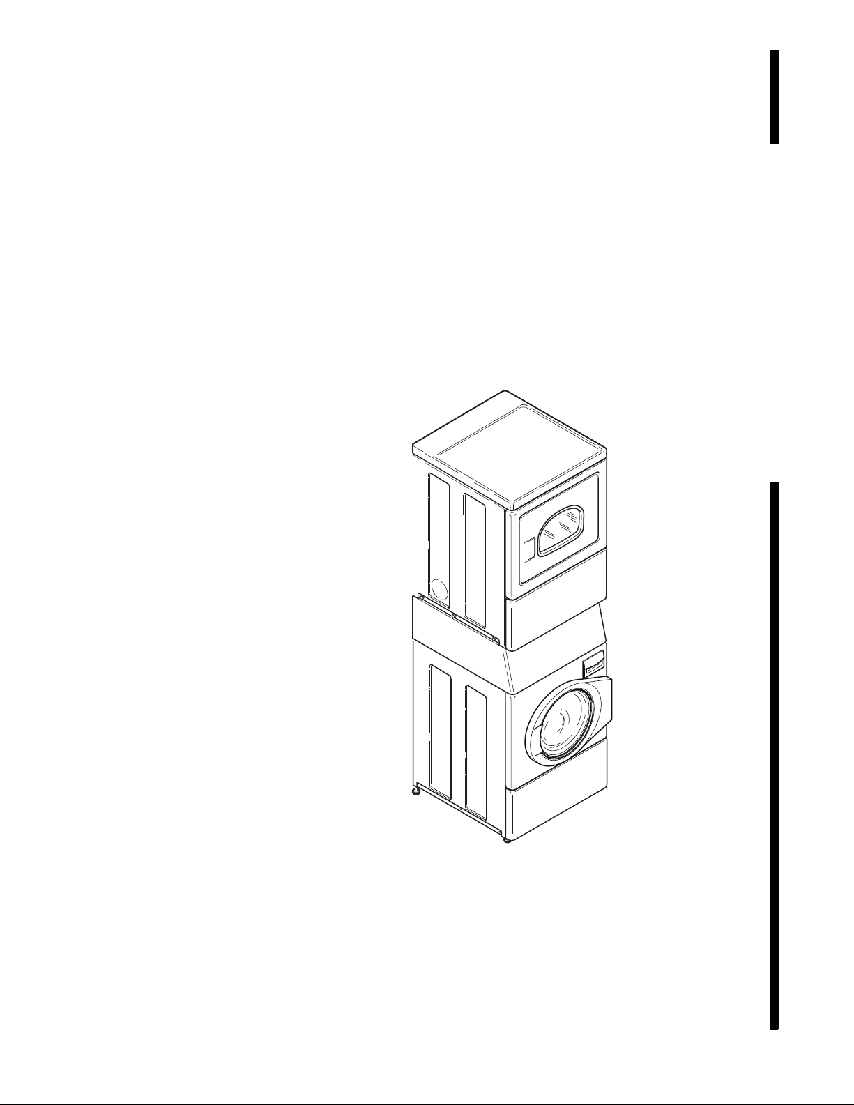
Homestyle
SWD456C
Stacked Washer/
Dryers
Refer to Page 6 for Model Numbers
Troubleshooting
SWD456C
Page 2

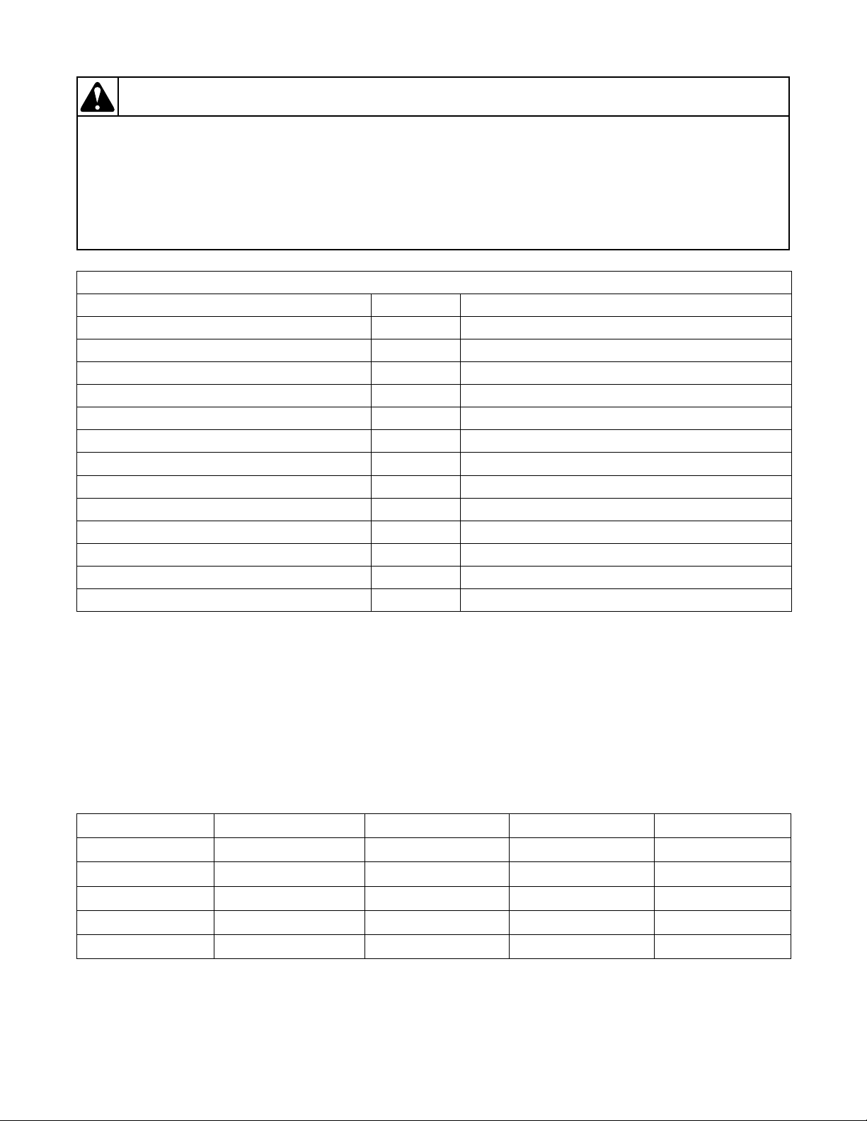
Table of
Section 1 – Safety Information ...............................................................3
Locating an Authorized Servicer...........................................................4
Contents
Section 2 – Introduction ..........................................................................5
Customer Service...................................................................................5
Nameplate Location...............................................................................5
Model Identification ..............................................................................6
Theory of Operation ..............................................................................7
Section 3 – General Troubleshooting.....................................................8
1. Keypad Combinations...................................................................8
2. Factory Test Procedure ...............................................................10
3. Motor Circuit...............................................................................16
4. Dipswitch Configuration.............................................................17
5. Troubleshooting Knocking Noise ...............................................18
6. Explanation of LEDs on Drive Control ......................................18
7. Door Fails to Unlock at End of Cycle.........................................18
8. No Spin .......................................................................................18
9. Excessive Vibration and/or Noise During Spin..........................20
10. Excessive Cycle Time.................................................................21
Section 4 – Dryer Control Troubleshooting ........................................22
7. Dryer Error Code Listing ............................................................22
8. Dryer Motor Does Not Run ........................................................24
9. Dryer Stops in Cycle; Quits After the First Few Loads;
Has a Burning Smell; Cycles On Motor Thermal Protector .......26
10. Dryer Motor Runs But Cylinder Does Not Turn ........................27
11. Dryer Motor Does Not Stop .......................................................28
12. Dryer Runs Only When Door is Open ........................................29
13. Dryer Heating Assembly Does Not Heat or
Burner Does Not Ignite...............................................................30
14. Igniter Does Not Glow (Gas Supply Sufficient)
– Gas Dryer Models ....................................................................32
15. Burner Ignites and Goes Out Repeatedly
– Gas Dryer Models ....................................................................33
16. Igniter Glows But Burner Does Not Ignite
– Gas Dryer Models ....................................................................34
17. Dryer Heater Assembly or Burner Shuts Off Prematurely .........35
18. Dryer Heater Assembly or Burner Repeatedly Cycles
Off On Limit Thermostat ............................................................36
19. Dryer Heater Assembly or Burner Does Not Shut Off ...............38
20. Clothes Do Not Dry in Dryer......................................................39
21. Timer Does Not Advance in Automatic Cycle ...........................40
22. Clothes Are Too Hot When Removed From Dryer ....................41
23. Excessive Chattering or Vibrating Noise in Dryer .....................42
24. Excessive Humming or Whistling Noise in Dryer......................43
1
Page 3

Section 5 – Washer Control Troubleshooting.....................................44
25. Error Codes .................................................................................44
26. No keypad Function ....................................................................51
27. No Visible Display on Control....................................................52
28. Washer Will Not Start – “do” Displayed....................................54
29. Washer Will Not Start – “Er”, “dl” on Display ..........................56
30. Washer Will Not Fill (Machine Empty,
No “Er”, “PS” on Display)..........................................................58
31. Washer Overflows.......................................................................60
32. Pump or Drain Valve Does Not Operate ....................................62
33. Motor Does Not Run (“Ed”, “29” on Display) ...........................64
34. Washer Will Not Heat (Models Equipped with Heater)
(“Er”, “oP” or “Er”, “SH” Displayed) ........................................66
35. Washer Will Not Heat (Models Equipped with Heater) .............68
Section 6 – Adjustments ........................................................................70
36. Cabinet Leveling Legs ................................................................70
37. Washer Loading Door.................................................................71
38. Washer Motor Belt Tension........................................................72
39. Washer Door Catch.....................................................................73
40. Shipping Braces ..........................................................................75
41. Burner Flame (Gas Models)........................................................76
Section 7 – Dryer Test Procedures .......................................................77
42. Timer Contacts............................................................................77
43. Fabric Selector Switch ................................................................78
44. Drive Motor.................................................................................79
45. Motor Switch...............................................................................82
46. Burner System Operation............................................................84
47. Electrical Circuit To Ignition System (Gas Models) ..................85
48. Gas Valve Coils Check (Gas Models) ........................................85
49. Sensor Check (Gas Models)........................................................86
50. Igniter Check (Gas Models)........................................................86
51. Thermal Fuse (Electric Models) .................................................87
52. Heater Assembly (Electric Models)............................................87
53. Cycling or Limit Thermostat.......................................................87
54. Door Switch ................................................................................88
Section 8 – Internal Wiring of Dryer Motor Switch...........................89
Section 9 – Cycle Sequence Charts.......................................................90
2 806221
Page 4
Section 1
• Failure to install, maintain, and/or operate this machine according to the manufacturer’s
instructions may result in conditions which can produce serious injury, death and/or
property damage.
• Do not repair or replace any part of the machine or attempt any servicing unless specifically
recommended or published in this Service Manual and that you understand and have the
skills to carry out.
• Whenever ground wires are removed during servicing, these ground wires must be
reconnected to ensure that the machine is properly grounded and to reduce the risk of fire,
electric shock, serious injury, or death.
W284
WARNING
Safety Information
Throughout this manual and on machine decals, you will find precautionary statements (“CAUTION,”
“WARNING” and “DANGER”) followed by specific instructions. These precautions are intended for the personal
safety of the operator, user, servicer, and those maintaining the machine.
DANGER
Danger indicates an imminently hazardous situation that, if not avoided, will cause severe personal injury or death.
WARNING
Warning indicates a hazardous situation that, if not avoided, could cause severe personal injury or death.
CAUTION
Caution indicates a hazardous situation that, if not avoided, may cause minor or moderate personal injury or property
damage.
Additional precautionary statements (“IMPORTANT” and “NOTE”) are followed by specific instructions.
IMPORTANT
The word “IMPORTANT” is used to inform the reader of specific procedures where minor machine damage will
occur if the procedure is not followed.
NOTE
The word “NOTE” is used to communicate installation, operation, maintenance or servicing information that is
important but not hazard related.
In the interest of safety, some general precautions relating to the operation of this machine follow.
806221 3
Page 5
Safety Information
To reduce the risk of electric shock, fire, explosion, serious injury or death:
• Disconnect all electric power to the machine and accessories before servicing.
• Close gas shut-off valve to gas dryer before servicing.
• Never start machine with any guards/panels removed.
• Whenever ground wires are removed during servicing, these ground wires must be
re
connected to ensure that the machine is properly grounded.
• Washer motor not grounded! Disconnect electric power before servicing motor.
W502
WARNING
Repairs that are made to your products by unqualified persons can result in hazards due to
improper assembly or adjustments subjecting you, or the inexperienced person making such
repairs, to the risk of serious injury, electrical shock, or death.
W007
WARNING
If you or an unqualified person perform service on your machine, you must assume the
responsibility for any personal injury or property damage which may result. The manufacturer
will not be responsible for any injury or property damage arising from improper service and/or
service procedures.
W286
WARNING
NOTE: The WARNINGS and IMPORTANT INSTRUCTIONS appearing in this manual are not meant to
cover all possible conditions and situations that may occur. Common sense, caution and care must be
exercised when installing, maintaining or operating the machine.
Always contact your dealer, distributor, service agent or the manufacturer about any problems or conditions you do
not understand.
Locating an Authorized Servicer
Alliance Laundry Systems is not responsible for personal injury or property damage resulting from improper
service. Review all service information before beginning repairs.
Warranty service must be performed by an authorized technician, using authorized factory parts. If service is
required after the warranty expires, Alliance Laundry Systems also recommends contacting an authorized technician
and using authorized factory parts.
4 806221
Page 6

Section 2
SWD1716S
Nameplate
Nameplate
SWD1716S
Introduction
Nameplate Location
When calling or writing about your product, be sure to
mention model and serial numbers. Model and serial
numbers are located on nameplate(s) as shown.
806221 5
Page 7

Introduction
Model Identification
Information in this manual is applicable to these models.
ATEE9AWP433AW01
ATGE9AWP303AW01
BTEE6ASP173TW01
BTEE6ASP283CW01
BTGE6ASP093CW01
BTGE6ASP113TW01
FTEE5ASP303NW10
FTEE5ASP303ZW01
FTGE5ASP303NW10
LTEE5ASP153TW01
LTEE5ASP173TW01
LTEE5ASP293CW01
LTEE5ASP303ZW01
LTEE5ASP333NW01
LTEE5ASP433AW01
LTEE5ASP433AW12
LTEE5ASP543NW23
LTGE5ASP113JW01
LTGE5ASP113TW01
LTGE5ASP303AW01
LTGE5ASP303AW12
LTLE5ASP543NW23
UTEE5ASP173TW01
UTEE5ASP173TW08
UTEE5ASP283CW01
UTGE5ASP113TW01
UTGE5ASP113TW08
YTEE5ASP173TW01
YTEE5ASP283CW01
YTGE5ASP093CW01
YTGE5ASP113TW01
6 806221
Page 8

Introduction
Theory of Operation
General (Dryer)
The dryer uses heated air to dry loads of laundry.
When the motor is started, the exhaust fan pulls fresh
air in through louvers at the rear of the dryer and over
the heat source (burner flame for gas and heating
element for electric). The heated air moves through the
heater duct and into the cylinder, where it circulates
through the wet load. The air then passes through the
lint filter, air duct and exhaust fan, where it is vented
to the outdoors.
General (Washer)
This frontload washer provides some of the same
principles of operation as the typical topload washers.
It senses water level, it dispenses the desired laundry
detergent, agitates the clothes for good cleaning action,
removes the water out of the washer and spins the
clothing in preparation for the dryer.
The difference in operation is primarily the rotational
washing agitation created for the horizontal basket and
drum. This agitation tumbles the clothes in a clockwise,
pause, and counter-clockwise direction. This reversing
tumbling action provides an efficient washing process
and requires less laundry detergent and less water.
The cycle begins by locking the loading door after the
vend is satisfied. The type of cycle and water
temperature are determined by the appropriate pads on
the electronic control.
The inner basket starts agitating during the wash water
fill. A column of air is trapped in a pressure bulb and
hose. The air pressure continues to increase as the inner
basket fills with water with the pressure sensor
monitoring the water level.
The agitate step tumbles the clothing in a clockwise
direction for a period of time, pauses for a period of
time and then tumbles the clothing in a
counterclockwise direction for a period of time. This
agitation continues until the end of the wash cycle. The
machine then stops agitating and turns on the pump or
drain valve which removes the wash water.
After all the rinse cycles have been completed, the
washer goes into a final spin cycle to extract as much
water as possible from the clothing to prepare them for
the dryer. The spin speeds and duration of this final
spin cycle are determined by the type of wash cycle
selected.
NOTE: Washer may not reach 1200 RPM because
of an out-of-balance condition. Control may limit
speed to 1000, 800, 650 or 500 RPM depending on
severity of out-of-balance condition.
Technical (Washer)
The basic operational system of this washer consists of
the electronic control, the inverter control, pressure
sensor, water valves, electric pump (or drain valve)
and A.C. motor.
The electronic control performs all control and timing
functions. The electronic control sends simple speed
and output commands to the inverter control via serial
communication. The drive control powers the door
lock, pump (or drain valve), motor, water valves and
heater (if equipped).
The drive control powers the A.C. motor and performs
all motor control functions. The drive control also
powers the water valves, dispenser valves and door
lock. The drive control is powered through the door
switch and electronic control. The drive control also
alerts the electronic control to any errors in the motor.
Before entering any spin step the drive control
measures out-of-balance. The drive control will try to
redistribute the clothes if an out-of-balance condition
exists by limiting the spin speed to several speeds
depending on the severity of the out-of-balance
condition. If the out-of-balance condition is severe
enough the drive control will limit speed to 90 RPM
and will not spin.
NOTE: An additional out-of-balance switch is used
to detect any out-of-balance condition during spins.
If this switch opens during a spin step, the drive
control immediately stops and then restarts the
spin.
Upon completion of the wash cycle, the machine goes
into a rinse cycle. Fresh cold water is brought into the
inner basket via the mixing valve until the fill level is
satisfied. The rinse cycle consists of agitation for a
predetermined amount of time then a spin mode with
the pump running where the machine goes into a series
of spins.
806221 7
Page 9
General Troubleshooting
To reduce the risk of electric shock, fire, explosion, serious injury or death:
• Disconnect electric power to the washer before servicing.
• Never start the washer with any guards/panels removed.
• Whenever ground wires are removed during servicing, these ground wires must
be
re
connected to ensure that the washer is properly grounded.
• Motor not grounded! Disconnect electric power before servicing motor.
W485
WARNING
FLW1815S
1
2
3
5
6
7
8
9
10
11
12
16
17
21
28
22
23
26 27
25
24
13 18
14 19
15 204
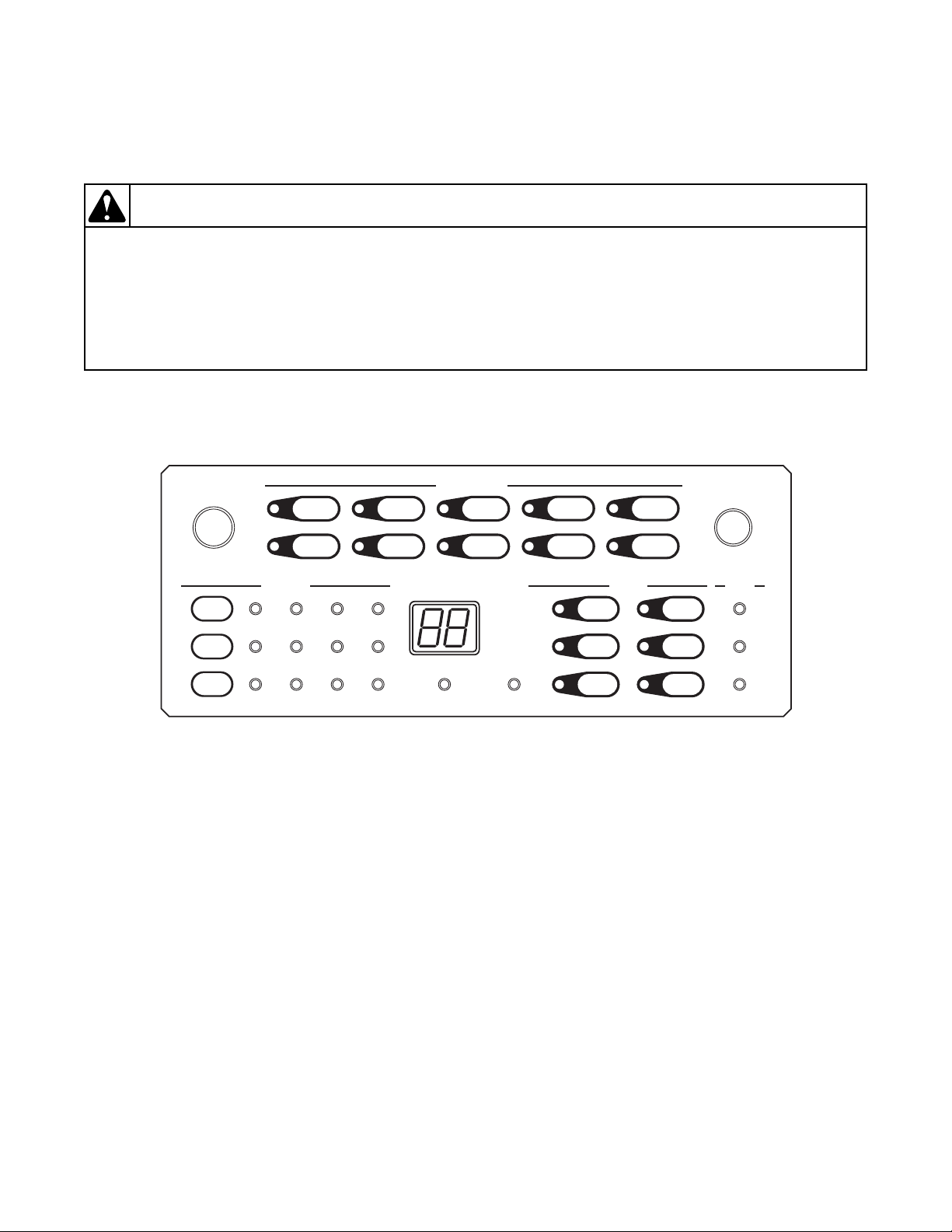
1. Keypad Combinations
Section 3
Figure 1
8 806221
Page 10
General Troubleshooting
To reduce the risk of electric shock, fire, explosion, serious injury or death:
• Disconnect electric power to the washer before servicing.
• Never start the washer with any guards/panels removed.
• Whenever ground wires are removed during servicing, these ground wires must
be
re
connected to ensure that the washer is properly grounded.
• Motor not grounded! Disconnect electric power before servicing motor.
W485
WARNING
Testing Mode Keypad Entry
Function Keys Entry State
Enter/Exit Software Version Display Mode 7+8 Start Mode
Turn On/Off Rainbow Pizzazz Display 9+10 Start Mode
Toggle Keypad Acknowledgement 13+14 Start Mode
Toggle Suds Extra Time Mode 2+3 Start Mode and powered for less than 5 minutes
Enter Factory Test Mode 2+7 Start Mode and powered for less than 5 minutes
Enter/Exit Audit Display Mode 3+9 Start Mode
Enter/Exit Factory Test Counter Display Mode 2+9 Start Mode
Enter/Exit Show Mode 3+8 Start Mode
Enter/Exit Extra Water Mode 8+14 Start Mode and Default/Extra Water Dipswitch On
Enter/Exit Drive Version Display Mode 3+14 Start Mode
Rapid Advance Through Current Cycle Step 7+13 Run Mode
Enter/Exit Spin Retry Extra Time Toggle Mode 8+ 13 Start Mode and powered for less than 5 minutes.
Enter/Exit Water Level Display Mode 4+14 Any Mode except if Control Lock is On
Table 1
Water Level Display Mode
The control will read the current water level. The
display will show the water level least significant digits
in 0.1 inch precision which will override any other
display.
If the water level is a negative value, then the right most
decimal point is lit. If the value is greater than or equal
to 10.0 inches, LED number 28 will be lit. If the value
will be lit. If the value is greater than or equal to 30.0
inches, LEDs 28, 22 and 23 will be lit.
To exit this mode, the user can either press the two keys
used to enter this mode, press the Power/Cancel key, or
unplug the machine. This mode only overrides the
display, the machine will continue running any other
modes that it is in.
is greater than or equal to 20.0 inches, LEDs 28 and 22
Value Display # 28 Light On? # 22 Light On? # 23 Light On?
4.5 inches 45 No No No
-3.2 inches 32. No No No
12.4 inches 24 Yes No No
20.8 inches 08 Yes Yes No
42.9 inches 29 Yes Yes Yes
Tab l e 2
806221 9
Page 11

General Troubleshooting
To reduce the risk of electric shock, fire, explosion, serious injury or death:
• Disconnect electric power to the washer before servicing.
• Never start the washer with any guards/panels removed.
• Whenever ground wires are removed during servicing, these ground wires must be
reconnected to ensure that the washer is properly grounded.
• Motor not grounded! Disconnect electric power before servicing motor.
W485
WARNING
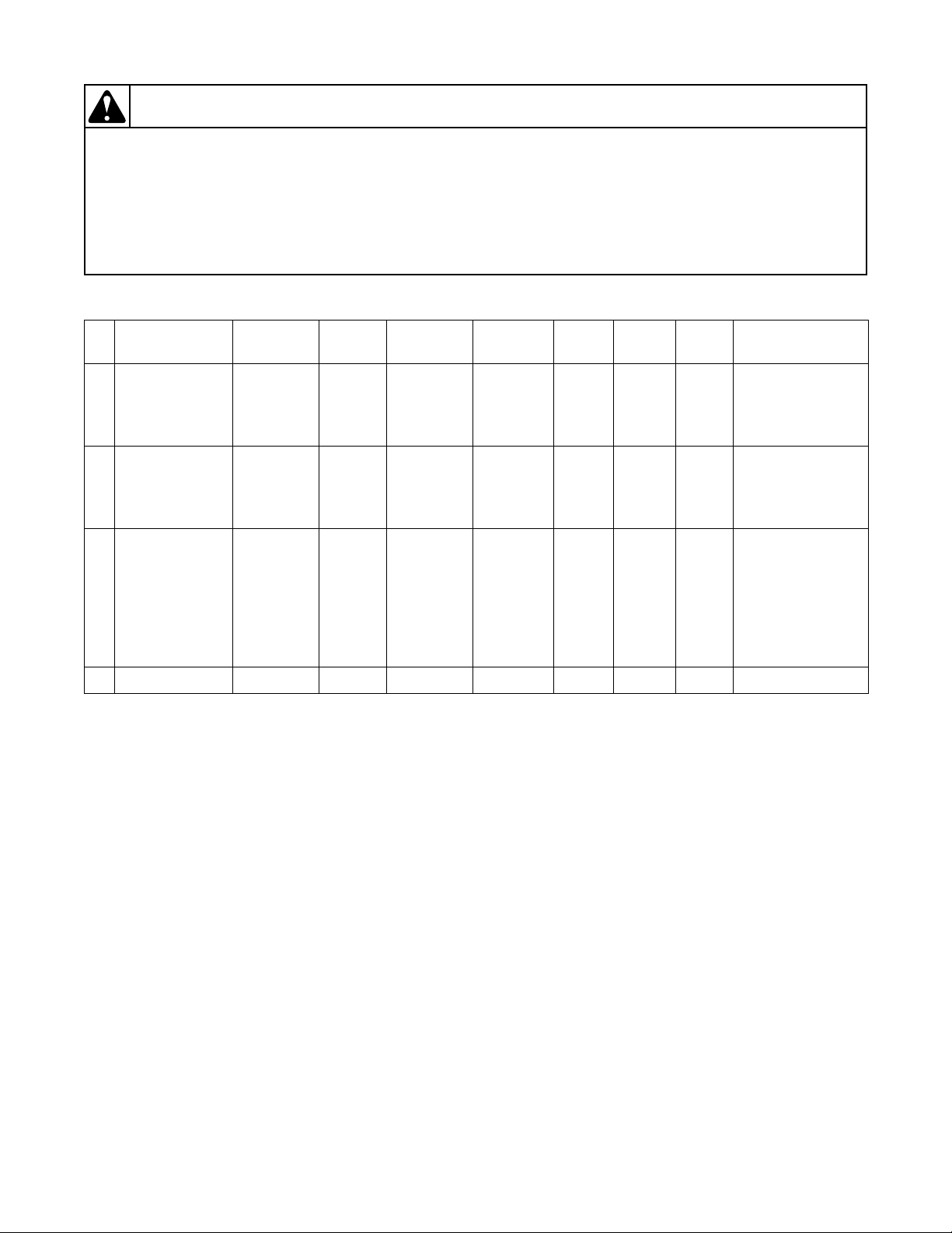
2. Factory Test Procedure
It is helpful to run the Factor Test Procedure first to
diagnose the machine’s issue. This procedure tests all
machine features and operations.
To Enter Factory Test Procedure
1. Be certain control is in Start Mode and less than
5 minutes after powering control.
2. Press keypads numbered 2 and 7 at the same time.
Refer to Figure 1.
3. When the control enters the Factory Test
Procedure, it will display the first test step,
Machine
4. To advance through the sequence of test step
press the Start/Pause keypad (No. 21). Refer to
Tabl e 3 for all tests in the Factory Test Procedure.
Type.
To Exit Factory Test Procedure
To exit the Factory Test Procedure, refer to Exit
column in Tabl e 3.
Factory Test Procedure Quick Reference Chart
NOTE: ES refers to the External Supply Outputs.
# Display
0 FL None Off None Unlocked Off Open 1 Control Type
1 XX None Off None Unlocked Off Open 1
2 HX None Off None Unlocked Off Open 1 Control Level
3 XX None Off None Unlocked Off Open 1
4 XX None Off None Unlocked Off Open 1
Status
LEDs Lit
Motor Valves Door Pump Dump Exit* Step
Software
Ve r s i o n #
Dipswitch Value
Display
Cycle
Configuration
s
Refer to
5PX
688
dO with door
7
10 806221
open
dC with door
closed
Keypad
Test
section
All plus
audio
signal on
high
None Off None Unlocked Off Open
Off None Unlocked Off Open 3 Keypad Test
Off None Unlocked Off Open 1 Show Mode
Table 3 (continued)
10
And
Then
1
Door Switch Test
Page 12

To reduce the risk of electric shock, fire, explosion, serious injury or death:
• Disconnect electric power to the washer before servicing.
• Never start the washer with any guards/panels removed.
• Whenever ground wires are removed during servicing, these ground wires must
be
re
connected to ensure that the washer is properly grounded.
• Motor not grounded! Disconnect electric power before servicing motor.
W485
WARNING
Table 3 (continued)
# Display
Status
LEDs Lit
Motor Valves Door Pump Dump Exit* Step
8 db None Off None Unlocked Off Open
9 XX None Off None Unlocked Off Open
General Troubleshooting
10, 12
And
Then
Drive Type
1
10, 12
And
Then
Drive Version #
1
dL when door
10
locks
dU when door
None Off None Locked Off Open1And
unlocks
Cold,
11 Cd Wash Off
Detergent,
Locked Off Closed 1
ES 1
Hot,
12 HS Wash Off
Softener,
Locked Off Closed 1
ES 2
13 PS Wash Off Hot, Cold Locked Off Closed
14 XX None Off None Locked Off Closed 1 Or 5 Heater Test
Hot, Cold,
Detergent,
Softener,
15 OF Wash Off
ES
Locked Off Closed
1, 2, 3, 4,
Cycle
Output
ES 3,
Cycle
Locked Off Closed 1 Low Agitate
Output
ES 4 Locked Off Closed 1 Regular Agitate
Table 3 (continued)
16 LA Rinse
17 rA Rinse
Low
Agitate
Regular
Agitate
806221 11
2 And
Then
8 And
Then
Door Lock Check
7
Cold, Detergent,
Output 1
Hot, Softener,
Output 2
Pressure Sensor
1
Overflow
1
Test
Fill
Page 13
General Troubleshooting
To reduce the risk of electric shock, fire, explosion, serious injury or death:
• Disconnect electric power to the washer before servicing.
• Never start the washer with any guards/panels removed.
• Whenever ground wires are removed during servicing, these ground wires must
be
re
connected to ensure that the washer is properly grounded.
• Motor not grounded! Disconnect electric power before servicing motor.
W485
WARNING
# Display
Status
LEDs Lit
Pu for pump
18
installed
dr for gravity
Rinse Off None Locked On Open 9
drain installed
19 actual RPM Spin
Table 3 (continued)
Motor Valves Door Pump Dump Exit* Step
Pump/Gravity
Drain
Fac-
tory
Spin
None Locked On Open 1 Factory Spin
Profile
20 bA Spin
Break-
away
Agitate
Hot, Cold,
Detergent,
Softener,
ES
1, 2, 3, 4,
Cycle
Output
Unlocked On Open
1, 1
Again
Then
4
Then
11
Breakaway
21 Pd Spin Off None Unlocked Off Open 13 Power Down
Tab l e 3
EXIT column key:
1-exit by Start/Pause keypress
2-exit by fill level satisfaction
3-exit when all keypads are pressed
4-exit when door is unlocked
5-exit when temp reaches 40
°C
6-exit when step timed out
7-exit when door locks
8-exit when overflow level reached
9-exit when drum is empty
10-exit when door is closed
11-exit when door is opened
12-exit when drive communication is established
13-exit when machine unpowered
12 806221
Page 14
To reduce the risk of electric shock, fire, explosion, serious injury or death:
• Disconnect electric power to the washer before servicing.
• Never start the washer with any guards/panels removed.
• Whenever ground wires are removed during servicing, these ground wires must
be
re
connected to ensure that the washer is properly grounded.
• Motor not grounded! Disconnect electric power before servicing motor.
W485
WARNING
Keypad Test
General Troubleshooting
Upon entry into this test, the control will display “P-”.
When a keypad is pressed the control will display “PX”
where X is the keypad number referenced in Tabl e 4.
For keypads 10 and greater the control will display
“XX” where XX is the keypad number. As each
keypad is pressed, the nearest LED
will light up and remain lit for the duration of the
keypad test. When all keypads have been pressed the
control will automatically advance to the next step.
Keypads that are not available on some controls do not
need to be tested. Refer to Figure 1 for keypad number
and LED references.
Keypad Numbers (some models may not have all keypads)
Display Key Number LED
P1
P2
P3 3 25
P4 4 24
P5 5 Next to keypad
P6 6 Next to keypad
P7 7 Next to keypad
P8 8 Next to keypad
P9 9 Next to keypad
10 10 Next to keypad
13 11 Next to keypad
1 22
2 26
14 12 Next to keypad
15 13 Next to keypad
16 14 Next to keypad
17 15 Next to keypad
18 16 Next to keypad
19 17 Next to keypad
20 18 Next to keypad
21 19 Next to keypad
22 20 Next to keypad
23 21 23
Tab l e 4
806221 13
Page 15
General Troubleshooting
To reduce the risk of electric shock, fire, explosion, serious injury or death:
• Disconnect electric power to the washer before servicing.
• Never start the washer with any guards/panels removed.
• Whenever ground wires are removed during servicing, these ground wires must
be
re
connected to ensure that the washer is properly grounded.
• Motor not grounded! Disconnect electric power before servicing motor.
W485
WARNING
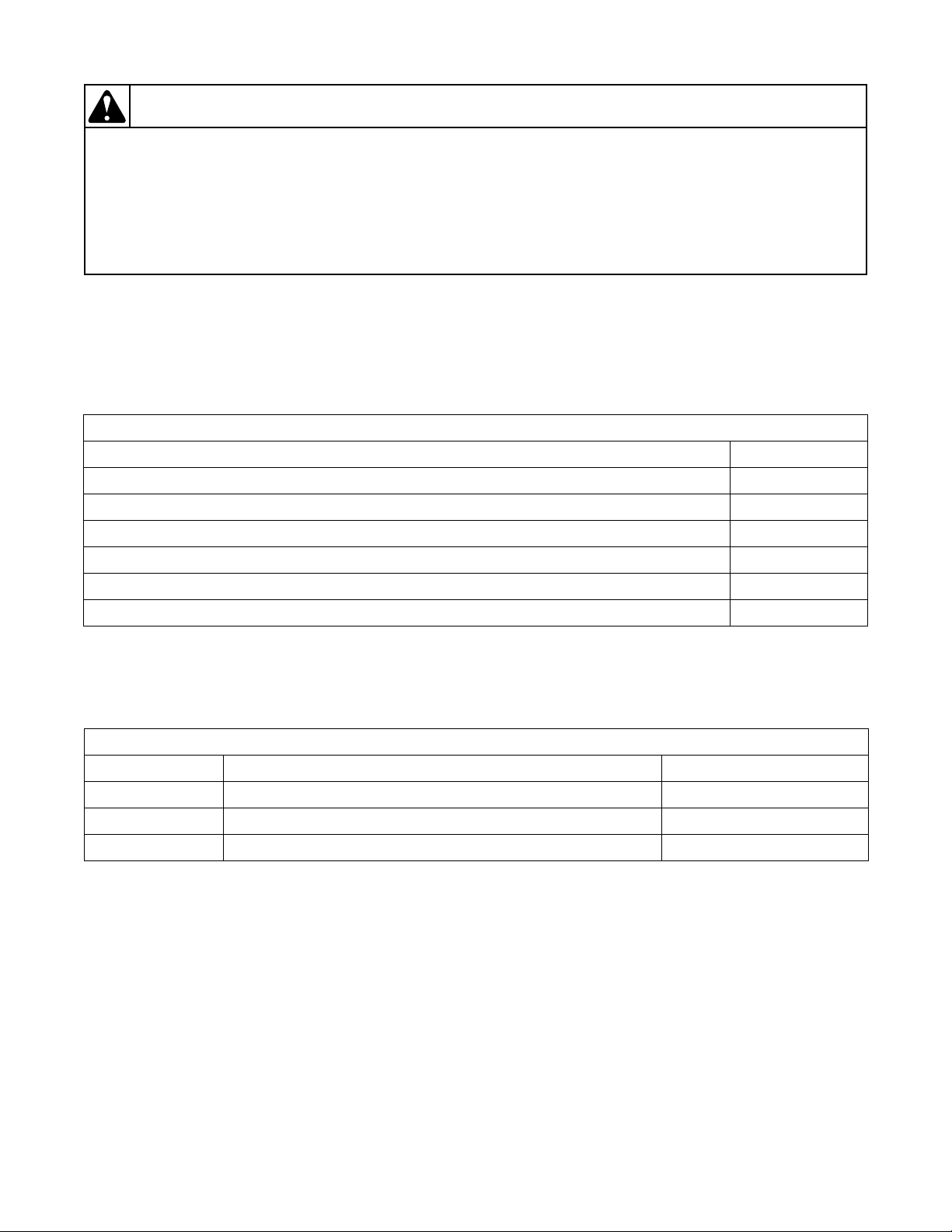
Dipswitch Value Display Test
This step displays the state of the Control
Configuration Dip Switches in hex, where the least
significant bit is Dip Switch #1 and the most significant
bit is Dip Switch # 8.
If a dipswitch is set to ON, the corresponding bit is set
to 1, otherwise if the dipswitch is set to OFF, the bit is
set to 0. The most common configurations are listed in
Tabl e 5.
Dipswitch Value Display
Machine Configuration Value
120 Volt with Electric Pump 00
120 Volt with Gravity Drain 80
240 Volt with Electric Pump 01
240 Volt with Gravity Drain 81
240 Volt Heater Machine with Electric Pump and Cool Down Enabled 61
240 Volt Heater Machine with Gravity Drain and Cool Down Enabled E1
Table 5
Cycle Configuration Test
This step verifies which set of cycles are used.
Cycle Configuration Display
Cycle Set Models Display
Default With “T” and “C” in the 12
Australia With “A” in the 12
th
character of the model number “dE”
th
character of the model number “AU”
International All Other models “in”
Tab l e 6
Cold/Detergent Fill
This step checks the cold water valve and the detergent/
bleach valve. The cold water fill valve, the detergent/
bleach valve and the External Supply Valve 1 turn on.
The valves will shut off once a low fill level is reached.
Pressure Sensor Fill
This step checks the analog water level input. When the
water fill level is satisfied, the water valves are turned
off. The control will not advance to the next step until
the normal fill level is satisfied.
Hot/Softener Fill
This step checks the hot water valve and the softener
valve. The hot water fill valve, the softener valve and
the External Supply Valve 2 turn on. The valves will
shut off once a medium fill level is reached.
14 806221
Page 16

General Troubleshooting
To reduce the risk of electric shock, fire, explosion, serious injury or death:
• Disconnect electric power to the washer before servicing.
• Never start the washer with any guards/panels removed.
• Whenever ground wires are removed during servicing, these ground wires must
be
re
connected to ensure that the washer is properly grounded.
• Motor not grounded! Disconnect electric power before servicing motor.
W485
WARNING
Heater (Heater Models Only)
This step checks the heater operation. The display
shows “xx”, where xx is the temperature in degrees
Celcius. The control will heat the water to 40 degrees
Celcius while displaying the temperature as it rises at a
rate of 1 degree. If the temperature sensor is open or
shorted, the display will show “Er” and “OP” or “SH”.
Overflow Test
This test checks the overflow setting for the water level
sensor. When the overflow level is reached, the water
valves, all External Supply Valves and the Cycle Run
Output will automatically turn off. The control will not
advance to the next step until the overflow level is
satisfied.
Low Agitate
This step checks the Low Agitate speed. The display
shows “LA”, the Rinse LED is on, the Auxiliary Output
3 is on, Cycle Run Output is on, and the machine enters
a low agitate. The control will remain in this mode until
the Start/Pause keypad is pressed.
Regular Agitate
This step checks the Regular Agitate speed. The
display shows “rA”, the Rinse LED is on, the Auxiliary
Output 4 is on, and the machine enters a regular agitate.
The control will remain in this mode until the Start/
Pause keypad is pressed.
Pump/Gravity Drain Test
This step checks the Pump output. The display shows
“Pu” for an electric pump or “dr” for a gravity drain,
the Rinse LED is on, and the Pump is turned on or the
Gravity Drain is opened. The control will only advance
to the next test step after the Water Level Sensor
indicates that the drum is empty.
Factory Spin
This step checks the spin speeds. The display shows the
most significant two digits of the actual RPM.
806221 15
The machine steps through spin speeds and maintains
each speed for a few seconds. After 1200 RPMs, the
motor will stop.This step lasts 4 minutes. All Out of
Balance checking is done and if either the out of
balance switch is hit or the OBL check fails and needs
to re-spin, the time will be reset indefinitely to allow
the load to be rebalanced so that it can spin up and reach
full speed. The control will advance to the next step if
the Start/Pause keypad is pressed at any time during
this step.
During this step if 800 RPMs is reached, LED number
26 will be lit. If 1000 RPMs is reached, the LED
number 25 will be lit. If 1200 RPMs is reached, the
LED number 24 will be lit, and if 1100 RPMs is
reached, the LED number 27 will be lit to indicate that
a passing speed has been reached. Refer to Figure 1 for
LED number definition.
Breakaway
This step checks the breakaway speed and the door
unlock function. All valves will be open at the
beginning of this step to allow the blowing out of the
valves by the factory. The Start/Pause keypad must be
pressed to start exiting the test. The first Start/Pause
keypress will turn off the water valves, the second
Start/Pause keypress will stop the motor and start the
unlock process. The third Start/Pause keypress will
start the unlock process. Once the door unlocks, it
needs to be opened to finally exit the test. The water
level sensor will be trimmed in this step after a 20
second delay and once the Start/Pause key is pressed
the first time.
During this step the LEDs for indicating speeds
reached from the Factory Spin step will remain lit in
this step.
Power Down
This is the final step of factory test procedure. The
control will display “Pd” to signify that the procedure
has been completed and that the user can safely unplug
the machine. Cycling power to the machine is the only
way to resume normal operation.
Page 17
General Troubleshooting
To reduce the risk of electric shock, fire, explosion, serious injury or death:
• Disconnect electric power to the washer before servicing.
• Never start the washer with any guards/panels removed.
• Whenever ground wires are removed during servicing, these ground wires must
be
re
connected to ensure that the washer is properly grounded.
• Motor not grounded! Disconnect electric power before servicing motor.
W485
WARNING
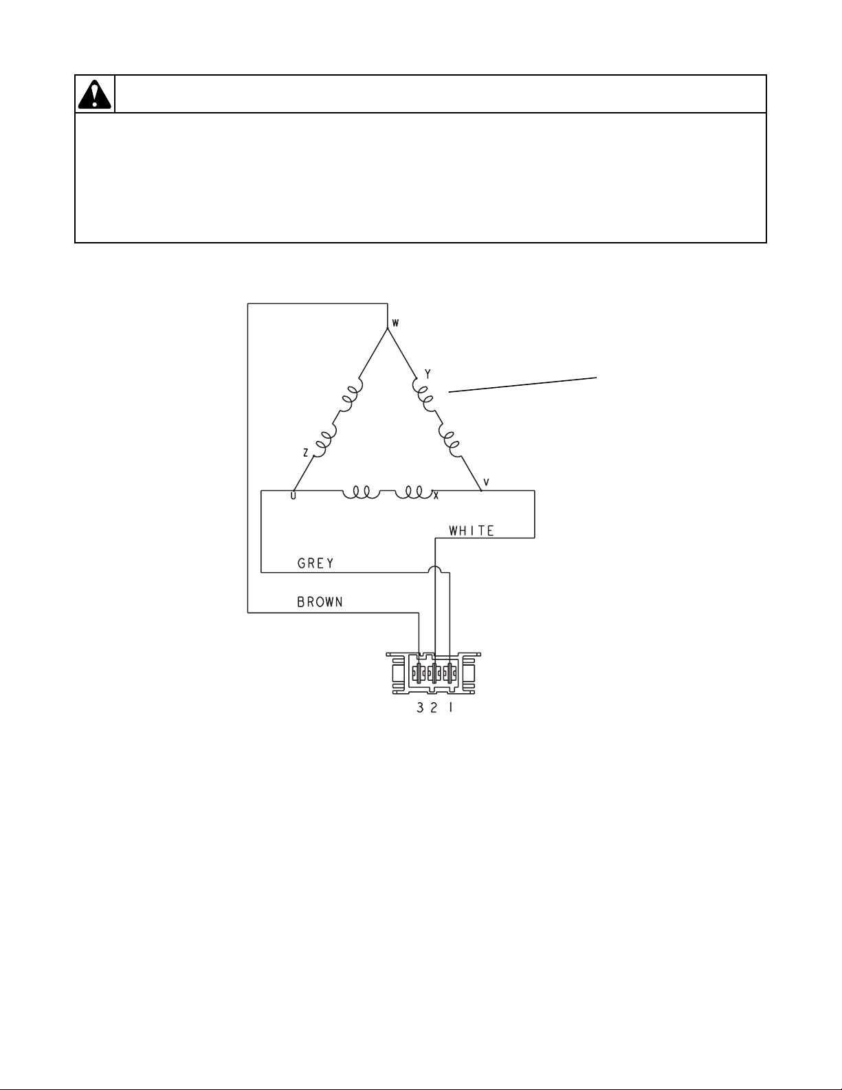
FLW1792S
Windings
FLW1792S
3. Motor Circuit
Windings Resistance:
Approx. 3.38 ohms
16 806221
Page 18
General Troubleshooting
To reduce the risk of electric shock, fire, explosion, serious injury or death:
• Disconnect electric power to the washer before servicing.
• Never start the washer with any guards/panels removed.
• Whenever ground wires are removed during servicing, these ground wires must
be
re
connected to ensure that the washer is properly grounded.
• Motor not grounded! Disconnect electric power before servicing motor.
W485
WARNING
4. Dipswitch Configuration
OFF ON
Switch 1 120 Volt AC Supply 240 Volt AC Supply
Switch 2* Energy Saving Cycles Standard Cycles
Switch 3** Default Water Level Increased Water Level
Switch 4
Switch 5 Unused Unused
Switch 6 Cool Down Disabled Cool Down Enabled
Switch 7 Heater Disabled Heater Enabled
Leak and Slow Drain Errors Off
Leak and Slow Drain Errors
On
Switch 8 Electric Pump Gravity Drain
Tab l e 7
*Switch 2
When set to OFF, energy saving water and fill levels are used for the specific type/region of the machine. When set
to ON, energy saving cycle settings are not used.
**Switch 3
When set to OFF, the Default Water Levels are used. When set to ON, the owner can increase the water level using
the Extra Water Mode. Higher water levels are not recommended as they may result in water leaking from the
machine door.
806221 17
Page 19
General Troubleshooting
To reduce the risk of electric shock, fire, explosion, serious injury or death:
• Disconnect electric power to the washer before servicing.
• Never start the washer with any guards/panels removed.
• Whenever ground wires are removed during servicing, these ground wires must
be
re
connected to ensure that the washer is properly grounded.
• Motor not grounded! Disconnect electric power before servicing motor.
W485
WARNING
FLW1814S
1
4
3
2
5. Troubleshooting Knocking Noise
If a frontload washer produces a noise similar to a
kn
ock on a door, it might be due to a flat spot on
the belt. The knocking sound is made when
flat spo
during a ramp spin and fade after reaching a
higher RPM.
To correct this condition, replace the belt.
t hits the pulley. The knocking may occu
the
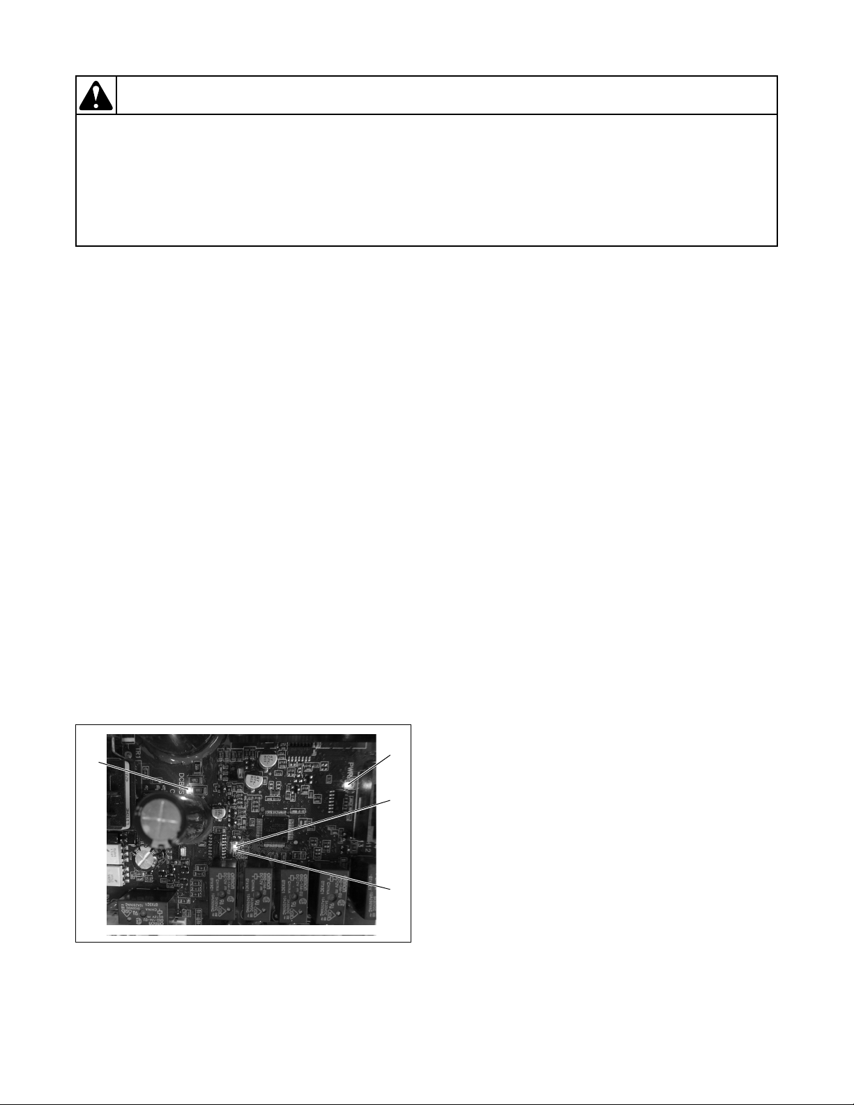
6. Explanation of LEDs on Drive Control
There are four LEDs on the control to assist with
troubleshooting (refer to Figure 2):
1. Green LED on constant = 5VDC power supp
sent
pre
2. Green LED flashing one second on/one second
off = drive control is active
3. Red LED flashing = drive contro
co
mmunicating with front end control
4. Red LED on constant = DC Bus Charged
NOTE: Drive is only powered when door is closed
and front end control turns it on.
l is
ly
7. Door Fails to Unlock at End of Cycle
If the door won’t unlock at the end of the cycle and the
r
cycle time is flashing in the display, the water might be
too hot to drain. Add a cool-down step to the cycle to
make sure the water will be cooled. Enable the cooldown feature by setting the cool down dip switch (#6)
to ON.
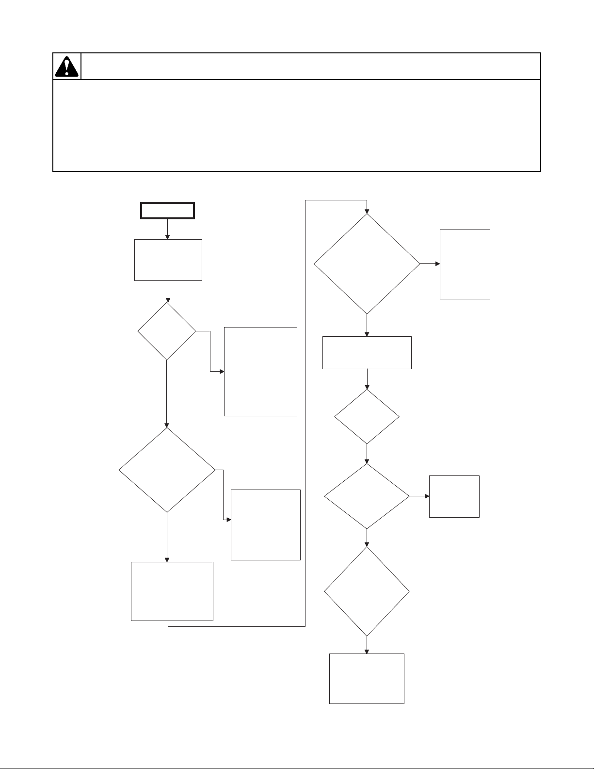
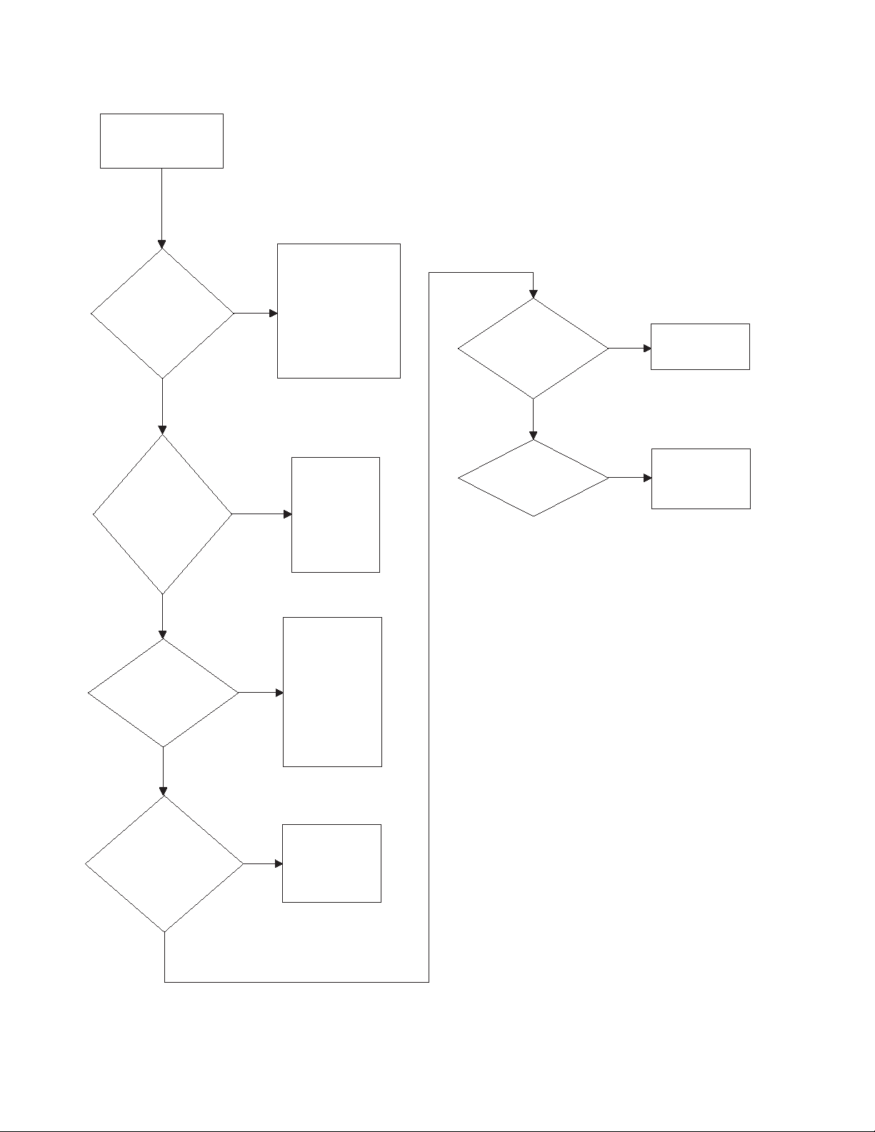
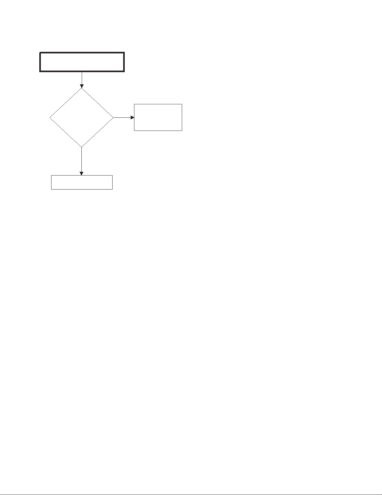
8. No Spin
A no spin condition is not caused by intermittent
operation of the motor or motor control (inverter
assembly). DO NOT replace these components for no
spin complaints if the unit passes the following
procedure:
Figure 2
18 806221
Page 20
To reduce the risk of electric shock, fire, explosion, serious injury or death:
• Disconnect electric power to the washer before servicing.
• Never start the washer with any guards/panels removed.
• Whenever ground wires are removed during servicing, these ground wires must
be
re
connected to ensure that the washer is properly grounded.
• Motor not grounded! Disconnect electric power before servicing motor.
W485
WARNING
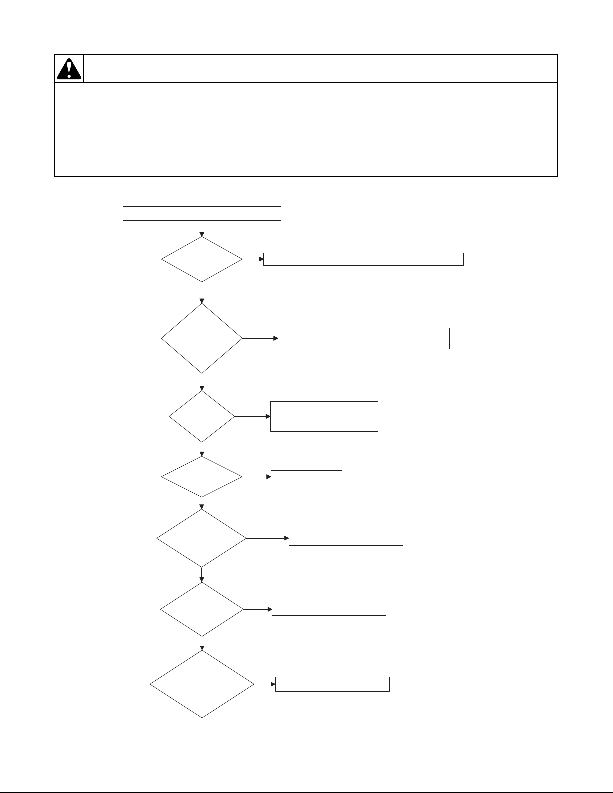
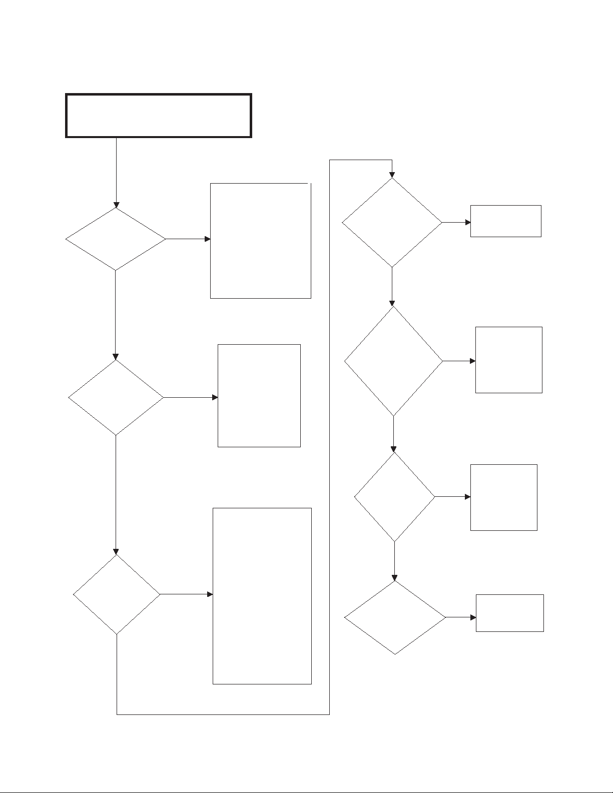
8. No Spin (continued)
FLW1816S
No spin
Allow unit to go
through complete
final spin cycle.
Does unit spin at
high speed?
Motor and
motor control
board are
operating
properly. Do
not replace
them.
Yes
Check for
obstruction
and damage
around drum.
No
With no load, rapid
advance to final spin
or run factory test
procedure to check
spin operation. Close
door and start washer.
BEFORE replacing
the motor control
board, conduct the
following tests.
No
Does
drum spin
freely by
hand?
Is load
out-of-
balance?
Unit makes multiple
attempts to rebalance out-ofbalance loads. If all
attempts fail, final
high speed spin is
aborted. ONLY
proper loading can
correct problem.
Yes
Is
there a slow
drain, clogged
pump or
oversudsing
condition?
Pressure sensor
must register an
"empty" condition
before unit will
enter spin. Clear
drain or pump. Use
less detergent.
Yes
No
No
Does unit
spin now?
No
Check for
broken shocks.
Yes
Using
Water Level
Display Mode, is
water level showing
below one inch
in spin
step?
Check pressure
hose for clog and
pressure sensor
wiring for connection
and damage.
No
FLW1816S
General Troubleshooting
806221 19
Page 21
General Troubleshooting
To reduce the risk of electric shock, fire, explosion, serious injury or death:
• Disconnect electric power to the washer before servicing.
• Never start the washer with any guards/panels removed.
• Whenever ground wires are removed during servicing, these ground wires must be
reconnected to ensure that the washer is properly grounded.
• Motor not grounded! Disconnect electric power before servicing motor.
W485
WARNING
FLW1809S
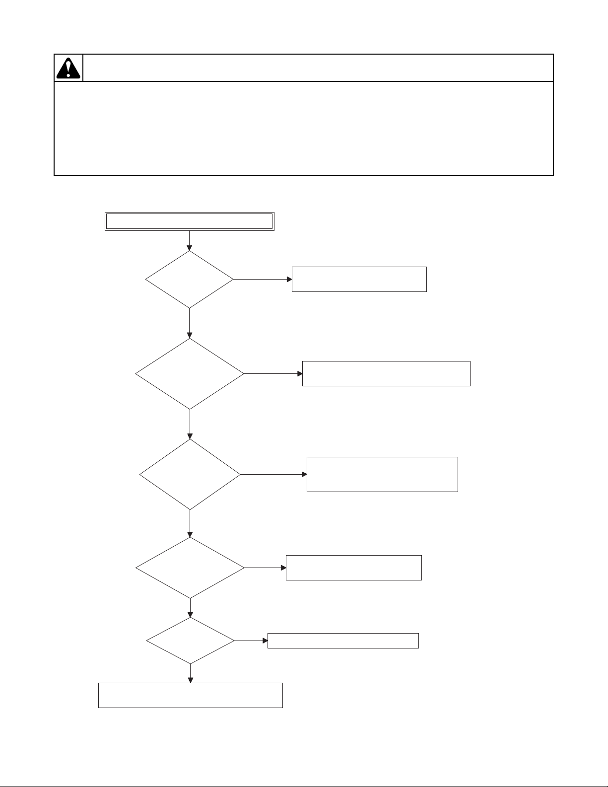
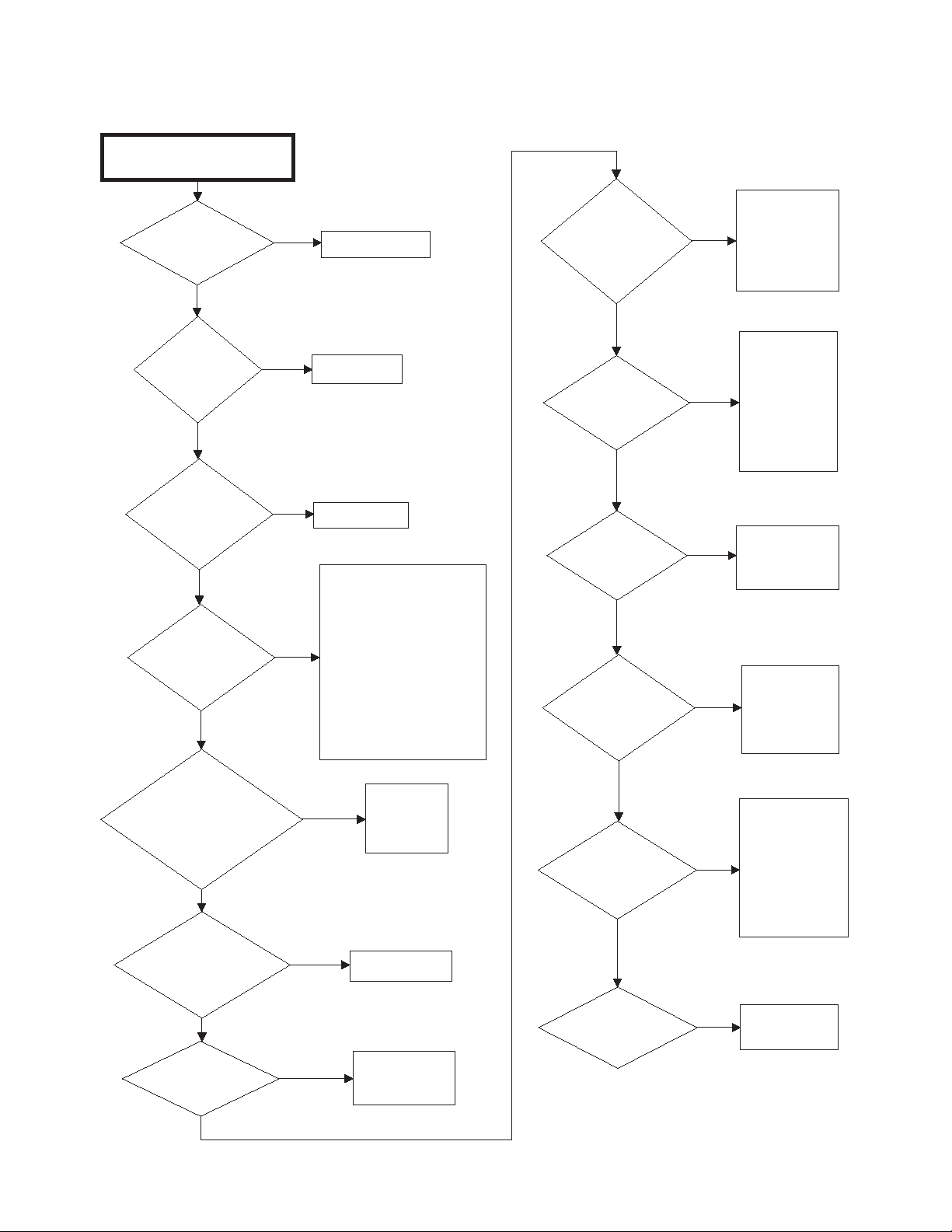
Excessive Vibration and/or Noise During Spin
Is
the load of proper
size?
Add or remove items as needed to ensure load size is correct.
No
Does
the wash load
contain the proper
mix of laundry
items?
Yes
Add or remove items as needed to ensure proper mix of
items (e.g. do not wash towels and sheets together).
No
Is
machine
level?
Yes
Level machine properly.
Refer to Installation Instructions.
No
Yes
Are
all panels on
machine?
Replace all panels.
No
Yes
Are
the front and rear
bearings making
excessive
noise?
Replace the bearings as needed.
Yes
Lift up on
the basket at the
front of the tub. Is there any
up and down play that would
indicate bearing
wear?
No
Replace the bearings as needed.
Yes
Are
motor and drive
pulleys aligned and
on tight?
Align/tighten pulleys as needed.
No
FLW1809S
9. Excessive Vibration and/or Noise During Spin
20 806221
Page 22
To reduce the risk of electric shock, fire, explosion, serious injury or death:
• Disconnect electric power to the washer before servicing.
• Never start the washer with any guards/panels removed.
• Whenever ground wires are removed during servicing, these ground wires must be
reconnected to ensure that the washer is properly grounded.
• Motor not grounded! Disconnect electric power before servicing motor.
W485
WARNING
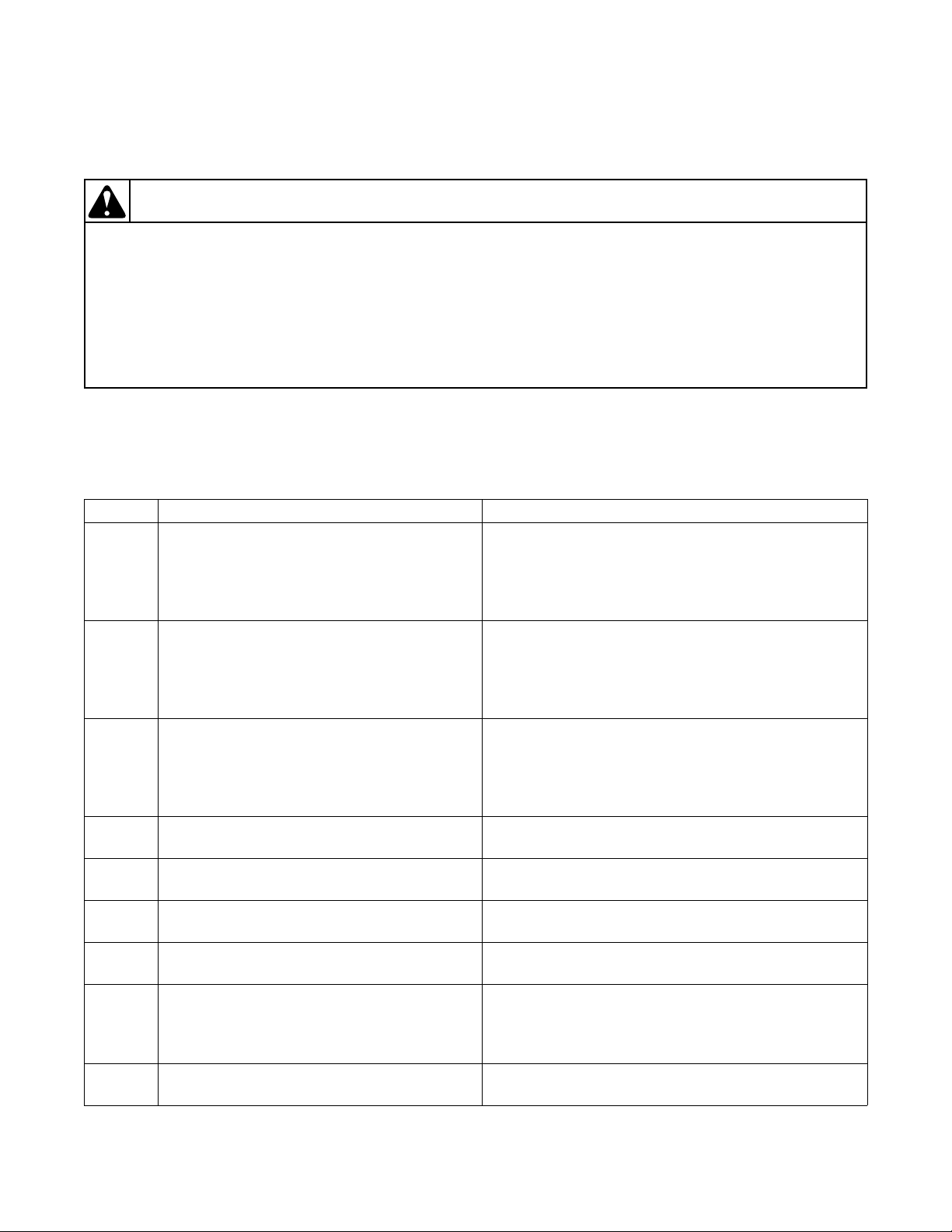
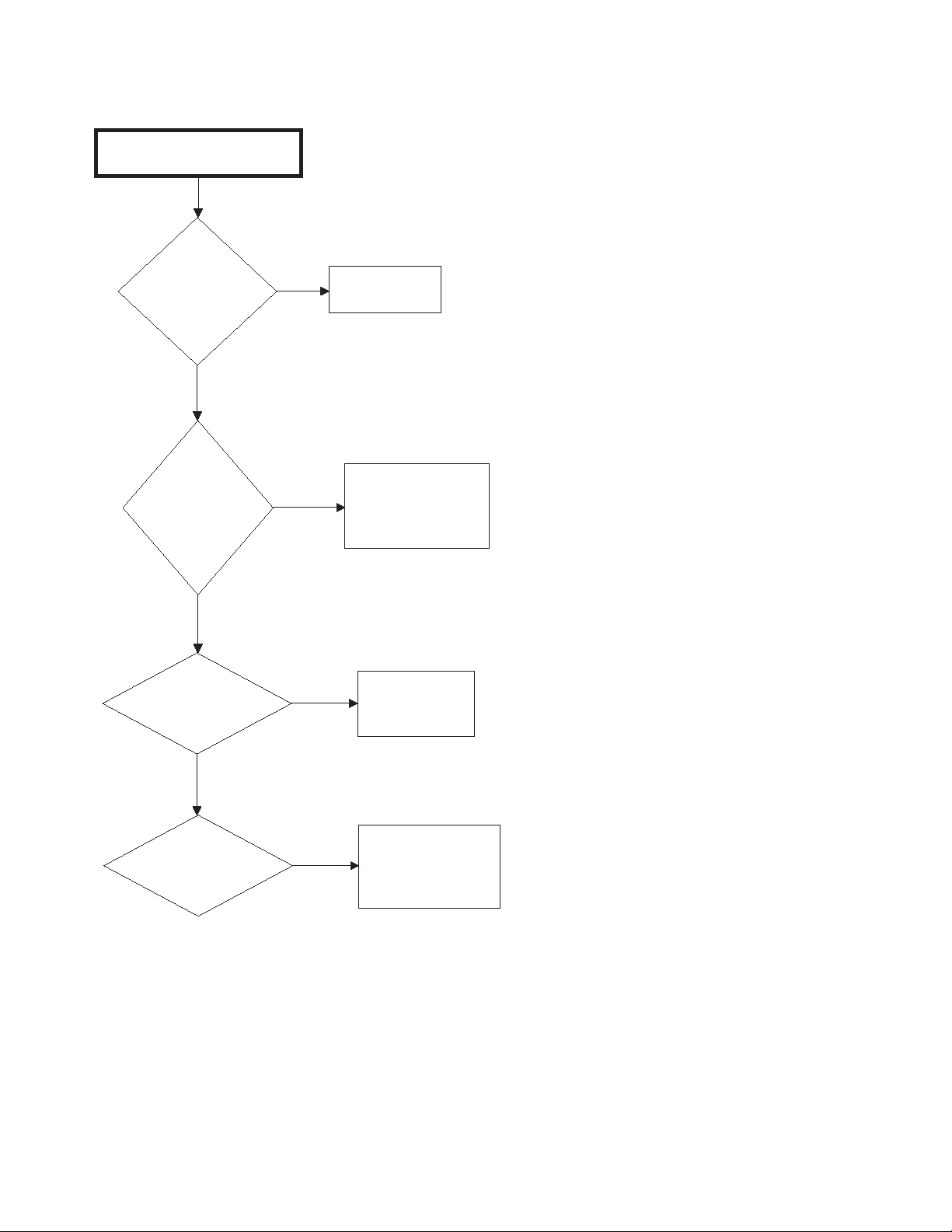
10. Excessive Cycle Time
FLW1819S
Excessive Cycle Time
Is water passing
through the drain during
fill?
Repair/replace drain valve as necessary.
Yes
Is the machine
slow to fill?
No
Check water pressure and/or check for
clogged screens in fill hoses.
Yes
Check pressure sensor and associated hoses for
obstructions or leaks. Repair/replace as necessary.
If
equipped with heat, is
it taking too long to
heat?
Troubleshoot heat output circuit.
No
Yes
Are
there load balance
issues?
Ensure machine is loaded properly.
Yes
No
No
Is there
an oversudsing
condition?
Reduce amount of detergent used.
Yes
No
FLW1819S
General Troubleshooting
806221 21
Page 23
Section 4
To reduce the risk of electric shock, fire, explosion, serious injury or death:
• Disconnect all electric power to the machine and accessories before servicing.
• Close gas shut-off valve to gas dryer before servicing.
• Never start machine with any guards/panels removed.
• Whenever ground wires are removed during servicing, these ground wires must be
re
connected to ensure that the machine is properly grounded.
• Washer motor not grounded! Disconnect electric power before servicing motor.
W502
WARNING
Dryer Control Troubleshooting
IMPORTANT: Refer to wiring diagram for aid in
testing dryer components.
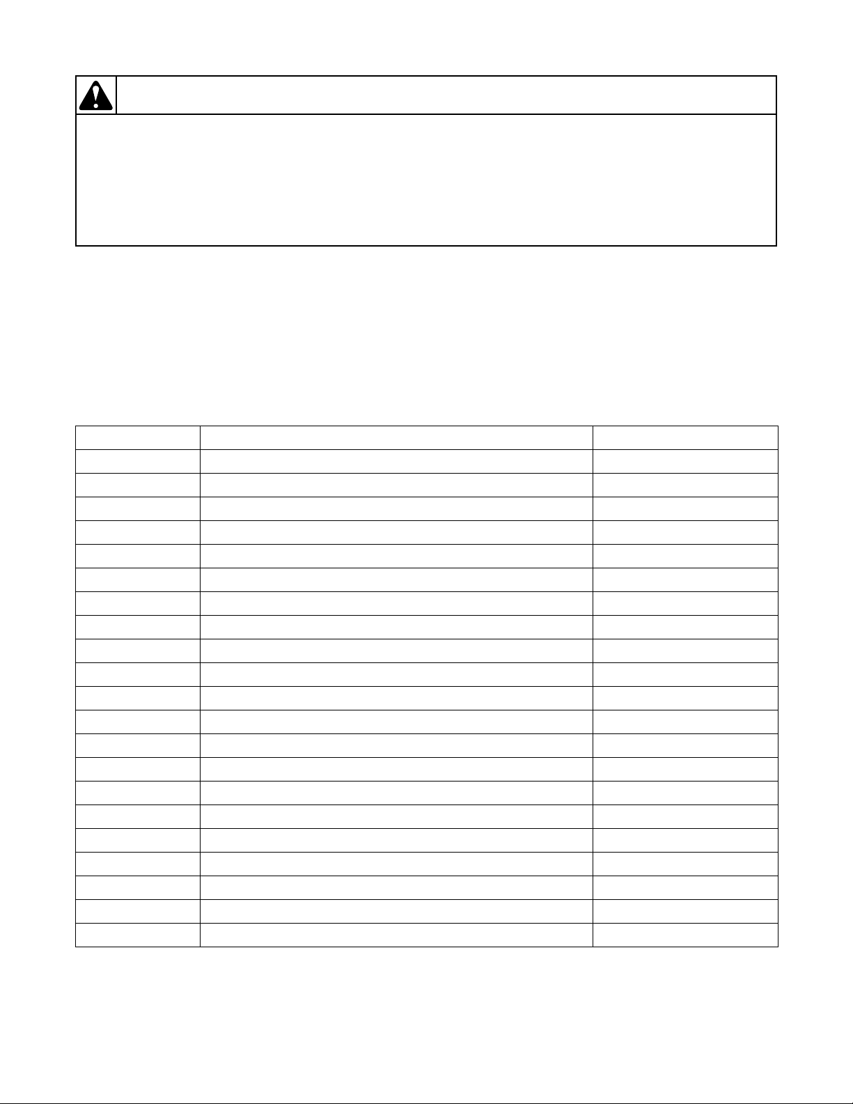
7. Dryer Error Code Listing
Display Description Cause/Corrective Action
Locked rotor error: The motor is not sensed as
rotating when it should be.
Open thermistor error: The thermistor circuit
is sensed as being physically open.
Shorted thermistor error: The thermistor
circuit is sensed as being shorted.
Motor output shorted error: Hardware error. Terminate cycle. Replace output board. Power down
Door input acquisition error: Hardware error. Terminate cycle. Replace output board. Power down
Centrifugal switch input acquisition error:
Hardware error.
High limit thermostat input acquisition error:
Hardware error.
Output board communication error:
Communication failure.
Output board not ready error: Hardware
failure.
(continued)
22 806221
Terminate cycle and check that nothing is obstructing
motor rotation. Check wire harness connection
between motor, user control and output board, or try
replacing the user control or the output board. Clear
error with a key press.
Remove any lint build up around thermistor. Check
wire harness connection between thermistor and
harness. If problem persists replace thermistor, harness
or output board. Thermistor must no longer be seen as
open to clear.
Remove any lint build up around thermistor. Check
wire harness connection between thermistor and
harness. If problem persists replace thermistor, harness
or output board. Thermistor must no longer be seen as
shorted to clear.
machine to clear.
machine to clear.
Terminate cycle. Replace output board. Power down
machine to clear.
Advance cycle to cool down. Replace output board.
Power down machine to clear.
Power down machine to clear, power up and try again.
If error persists, check harness connection between
user control and output board, or try replacing the user
control or the output board.
Terminate cycle. Replace output board. Power down
machine to clear.
Page 24

Dryer Control Troubleshooting
(continued)
Display Description Cause/Corrective Action
Brownout/voltage configuration error:
Unexpected supply voltage.
Check the harness connections between the user
control and the output board. If the user control was
replaced, set dipswitch #1 to the same setting as the
previous control. If reworking the machine to use a
different supply voltage, the dip switch #1 setting may
need to be changed. If the dip switch #1 setting is
changed, power down machine, power up and try
again.
Board ID error: Incorrect replacement
control.
Terminate cycle. Replace user control or output board
with correct part. Power down machine to clear.
806221 23
Page 25
Dryer Control Troubleshooting
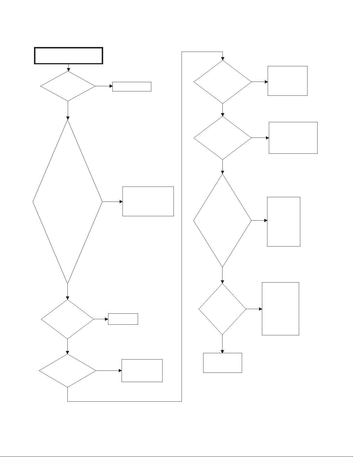
8. Dryer Motor Does Not Run
Dryer motor does not run.
Is power cord
plugged in?
Yes
Is electrical
power off or fuse
blown? Check
laundry room for
blown or loose
fuse(s), or open
circuit
breaker(s). The
dryer itself
doesn't have an
electrical fuse.
No
Plug in cord.
Yes
Turn power on or
replace fuse. Check
both fuses for
electric models.
Is
timer/electronic
control improperly
set?
No
Is
timer/electronic
control
inoperative?
No
Are motor
starting
functions
inoperative,
does not
start, or motor
just hum?
Yes
Yes
Yes
Reset
timer/electronic
control or try
another cycle.
Te st
timer/electronic
control and replace
if inoperative.
Refer to
Adjustments
section to
check motor
switch and
motor
windings.
No
No
Is loading
door closed?
Yes
Is door switch
inoperative?
No
No
Yes
Close door.
Test switch and
replace if
inoperative.
Is motor
dead,
won't run?
No
Continued on
next page.
Refer to
Adjustments
section to
Yes
check motor
switch, motor
windings and
main windings.
SWD1706S-a
24 806221
Page 26
8. Dryer Motor Does Not Run (continued)
SWD1706S-b
Continued from
previous page.
Is power cord
miswired?
Refer to wiring
diagram for
correct wiring.
Refer to wiring
diagram.
Is wiring
broken, loose
or incorrect?
Is motor wire
harness
connection
block loose?
Firmly press
connection
block onto
motor switch.
Remove belt
and
determine if
motor shaft
will spin.
Replace motor
if shaft is
locked up.
Is there a bind
in motor
bearing?
Is motor
centrifugal
switch sticky
or plugged
with lint?
Remove
dust or lint
and spray
with a
cleaner and
lubricant.
Wait two or three
minutes for
overload protector
to reset. If
protector cycles
repeatedly, refer
to next flowchart.
Has motor
overload
protector
cycled?
Yes
No
Yes
No
Yes
No
Yes
No
Yes
No
Yes
Dryer Control Troubleshooting
806221 25
Page 27
Dryer Control Troubleshooting
Dryer stops in cycle, quits after first few
loads, has burning smell or cycles on
motor thermal protector.
Is voltage
incorrect?
Refer to nameplate in
door well for correct
voltage. Refer to
Installation
Instructions (supplied
with unit) for
electrical
requirements.
Yes
Is clothes
load too
large?
No
Remove part of
load. A normal
washer load is a
normal dryer load.
Maximum load:
dryer cylinder one
half full of wet
clothes.
Yes
Is clothes
cylinder
binding?
Check cylinder for
binding and "out of
round" condition.
Check front and rear
bulkheads for
warping. Check
support rollers for
binding. Check
cylinder seals and
glides for wear or
damage. Check for
clothes lodged
between cylinder
baffle and bulkhead.
No
Yes
Is there
broken, loose
or incorrect
wiring?
Refer to wiring
diagram.
Yes
Are motor
switch
functions
inoperative?
Refer to
Adjustments
section to
check switch
and windings.
Yes
Is there a
short in
motor
winding?
No
Is a clothes
item caught in
fan?
Check fan for
obstruction.
Yes
No
SWD1690S
Refer to
Adjustments
section to
check switch
and windings.
No
Yes
No
9. Dryer Stops in Cycle; Quits After the First Few Loads; Has a Burning Smell; Cycles On Motor Thermal Protector
26 806221
Page 28
10. Dryer Motor Runs But Cylinder Does Not Turn
Dryer motor runs but
cylinder does not turn.
Is motor drive
pulley loose?
Tighten pulley.
Is belt
installed on
pulley?
No
Install belt.
No
Is cylinder
belt broken?
Replace belt.
Yes
Is clothes
cylinder
binding?
No
Check cylinder for
binding and "out of
round" condition. Check
front and rear
bulkheads for warping.
Check cylinder rollers
for binding. Check
cylinder seals and
glides for wear or
damage.
Is idler lever
spring broken,
weak or
disconnected?
Replace or
reconnect
spring.
Yes
Is there oil on
cylinder?
Wipe oil from
cylinder.
Yes
Is belt "inside
out" ?
Reinstall belt
with ribbed
surface
against
cylinder.
Yes
Is idler arm
binding?
Add grease
between idler
arm and
motor mount.
Replace idler
arm and bolt
if needed.
Yes
No
Is dryer
overloaded?
Remove some
laundry from
dryer.
Yes
No
SWD1691S
Yes
Yes
Yes
No
Is the wrong
motor
installed?
Refer to parts
manual for
correct motor
part number.
Is the wrong
belt installed?
Check belt
part number
against correct
part number in
parts manual
and replace
belt if needed.
Is idler arm
bent?
Replace idler
arm.
No
No
No
Yes
Yes
Yes
Is belt routed
on wrong side
of idler lever?
Reroute belt.
No
No
No
Yes
Dryer Control Troubleshooting
806221 27
Page 29
Dryer Control Troubleshooting
11. Dryer Motor Does Not Stop
Dryer motor does not stop.
Is wiring to
motor switch
incorrect?
No
Is motor
centrifugal
switch sticky
or plugged
with lint?
No
Is door switch
inoperative?
Yes
Yes
Refer to wiring
diagram.
Remove dust or lint
and spray with a
cleaner and
lubricant.
Yes
Test switch and
replace if
inoperative.
No
Is
timer/electronic
Yes
control
inoperative?
28 806221
Te st
timer/electronic
control and replace
if inoperative.
SWD1707S
Page 30
12. Dryer Runs Only When Door is Open
Dryer runs only when door is
open.
Is door switch
miswired?
Rewire door
switch. Refer to
wiring diagram.
Yes
SWD1693S
Replace door switch.
No
Dryer Control Troubleshooting
806221 29
Page 31

Dryer Control Troubleshooting
Dryer heating assembly does not
heat or burner does not ignite.
Is exhaust
system
improper or
inadequate?
Refer to
Installation
Instructions
(supplied with
unit) for
exhaust
requirements.
Is exhaust
duct made of
plastic or thin
foil?
No
Replace with
rigid or semirigid metal
exhaust duct.
Yes
Is house fuse
blown or
circuit breaker
tripped?
Check fuses or
circuit breakers.
Yes
Is limit
thermostat
inoperative?
Test
thermostat
and replace if
inoperative.
Yes
Electric Models:
Is heater
assembly
inoperative?
Test heater
assembly
and replace
if cold
Ohms do
not read
between 9
and 10.5
Ohms.
Yes
Electric
Models: Is
thermal fuse
inoperative?
Test thermal
fuse and
replace if
inoperative.
Yes
SWD1708S-a
Yes
No
Is drive
motor switch
inoperative?
Test switch
and replace if
inoperative.
No
Yes
Continued on
next page.
No
Is temperature
selector switch
set at FLUFF,
or inoperative?
Reset or test
switch and
replace if
inoperative.
Is
timer/
electronic control
improperly set
(set in a cool-down
period, or
a no heat
cycle)?
Reset
timer/electronic
control. Try
another cycle.
No
Yes
No
No
No
Yes
No
13. Dryer Heating Assembly Does Not Heat or Burner Does Not Ignite
30 806221
Page 32

13. Dryer Heating Assembly Does Not Heat or Burner Does Not Ignite
SWD1708S-b
Gas Models: Is
harness properly
connected to gas
controls?
Check
harness
connections
to gas valve
coils, sensor
and main
harness.
Reconnect as
required.
Test igniter
and replace if
inoperative.
Refer to Dryer
Test
Procedures
section.
Gas Models:
Is igniter
inoperative?
Gas Models:
Is sensor
inoperative?
Test sensor
and replace if
inoperative.
Continued from
previous page.
Yes
No
Yes
No
Gas Models:
Is gas flow in
gas orifice
restricted?
Clean out gas
orifice.
Yes
Is cycling
thermostat
inoperative?
Test
thermostat
and replace if
inoperative.
Yes
Is wiring
broken, loose
or incorrect?
Refer to wiring
diagram.
Yes
Is timer/
electronic control
noperative?
Test timer/electronic
control and replace
if inoperative.
No
Yes
No
Gas Models:
Are gas valve
coils
inoperative?
Test coils and
replace if
inoperative.
Refer to
Dryer Test
Procedures
section.
Yes
No
No
Gas Models:
Is gas supply
insufficient?
Check gas
shut-off valve
in dryer and
main gas line
valve. Open
partially closed
gas shut-off
valve or
correct low
gas pressure.
Yes
No
No
Yes
(continued)
Dryer Control Troubleshooting
806221 31
Page 33

Dryer Control Troubleshooting
Gas dryer models: Igniter
does not glow (gas supply
sufficient).
Is there power to
power leads on
valve (pink and
blue wires)?
Check
thermostats,
motor switch
and wiring.
No
Has flame
sensor failed
with contacts
open?
Yes
Replace sensor.
Yes
Is igniter broken
or open?
Replace igniter.
No
Yes
SWD1695S
14. Igniter Does Not Glow (Gas Supply Sufficient) – Gas Dryer Models
32 806221
Page 34

15. Burner Ignites and Goes Out Repeatedly – Gas Dryer Models
Gas dryer models: Burner ignites
and goes out repeatedly.
Is exhaust
system
improper or
inadequate?
Refer to
Installation
Instructions
(supplied with
unit) for
exhaust
requirements.
Yes
Is weather
hood flapper
restricted?
No
Is burner heat
holding sensor
contacts open?
Replace sensor
or correct gas
supply problem.
No
No
SWD1696S
Refer to
Installation
Instructions
(supplied with
unit) for
exhaust
requirements.
Yes
Is gas supply
insufficient?
Check gas supply
and pressure.
Make sure gas
shut-off valve is
turned on.
Is igniter
cracked?
Replace igniter
and bracket.
Are gas valve
coils
inoperative or
intermittent?
Check coils and
replace
appropriate coils.
Refer to Dryer
Test Procedures
section.
No
Yes
No
Yes
Yes
Yes
Dryer Control Troubleshooting
806221 33
Page 35

Dryer Control Troubleshooting
Gas dryer models: Igniter glows but
burner does not ignite.
Did sensor
fail in closed
position?
Replace sensor.
Yes
Is secondary
coil or holding
coil open?
No
Is gas supply
insufficient?
Check gas
supply and
pressure. Make
sure gas shutoff valve is
turned on.
No
Yes
SWD1697S
Replace gas
valve (in
warranty) or
replace coils
(out of
warranty). Refer
to Dryer Test
Procedures
section.
Yes
Are igniter
and bracket
improperly
installed on
burner tube
assembly?
Loosen screw and
properly position
igniter and bracket
on burner tube
assembly.
Is sensor
improperly
installed on
burner
housing?
Loosen screw
and properly
position the
sensor on the
burner housing.
No
Yes
Yes
No
16. Igniter Glows But Burner Does Not Ignite – Gas Dryer Models
34 806221
Page 36

Dryer Control Troubleshooting
Dryer heater assembly or burner
shuts off prematurely.
Is exhaust
system
improper or
inadequate?
Refer to
Installation
Instructions
(supplied with
unit) for
exhaust
requirements.
Yes
Is weather
hood flapper
restricted?
No
Gas Models: Is
gas supply
insufficient?
Check main gas
line shut-off
valve. Open
partially closed
gas shut-off
valve or correct
low pressure.
No
Yes
SWD1709S
Refer to
Installation
Instructions
(supplied with
unit) for
exhaust
requirements.
Yes
Gas Models: Is
dryer properly
equipped for type
of gas used?
Refer to "Gas
Burner Conversion
Procedures"
supplied in gas
burner conversion
kit.
Gas Models:
Is burner
flame
improperly
adjusted?
Adjust flame.
Refer to
Adjustments
section.
Cycling off on
limit
thermostat?
Momentarily
connect a
jumper wire
across
thermostat
terminals. If
heater element
heats or burner
ignites when
jumper wire is
connected, refer
to next flowchart.
No
Yes
Yes
No
Gas Models: Is
sensor contact
closing?
Replace sensor
or adjust burner
flame (refer to
Adjustments
section).
Yes
Is cycling
thermostat
inoperative?
Test thermostat
and replace if
inoperative.
Is wiring
broken, loose
or incorrect?
Refer to wiring
diagram.
No
No
Yes
Yes
Yes
Test timer/
electronic control and
replace if inoperative.
No
No
Yes
No
Is
timer/
electronic control
inoperative?
17. Dryer Heater Assembly or Burner Shuts Off Prematurely
806221 35
Page 37

Dryer Control Troubleshooting
Dryer heater assembly or burner repeatedly
cycles off on limit thermostat.
Is external exhaust
system longer or
providing greater
restriction than
recommended?
Refer to
Installation
Instructions
(supplied with
unit) for
exhaust system
requirements.
Is exhaust duct
made of plastic
or thin foil?
No
Replace with rigid
or semi-rigid metal
exhaust duct.
Yes
Is lint filter
clogged?
Clean lint
filter.
Yes
Is there lint in
internal dryer
ductwork?
No
Disassemble
dryer ductwork
and clean.
Is there lint
or other
obstruction in
external
exhaust
system?
Disassemble
and clean
exhaust
system.
Yes
Is hinged
damper on
exhaust system
weather hood
not free to
open?
Free hinged
damper or
replace
weather
hood.
Yes
Is limit
thermostat
cycling at too
low a
temperature?
Replace
thermostat.
Yes
SWD1710S-a
Yes
Yes
No
Continued on
next page.
No
No
No
No
18. Dryer Heater Assembly or Burner Repeatedly Cycles Off On Limit Thermostat
36 806221
Page 38

Dryer Control Troubleshooting
SWD1710S-b
Continued from
previous page.
Is there an air
leak at front
panel seal?
Check and
replace seal if
necessary.
Check and
replace seal(s)
if necessary.
Is there an air
leak at cylinder
seal(s)?
Is there an air
leak at blower
seal?
Check and
replace seal if
necessary.
Is there an air leak
around loading door?
(Door not sealing due
to damaged seal or
inoperative door
catch)?
Replace seal
or catch.
Yes
No
No
Yes
Yes
Yes
No
18. Dryer Heater Assembly or Burner Repeatedly Cycles Off On Limit
Thermostat (continued)
806221 37
Page 39

Dryer Control Troubleshooting
Dryer heater assembly or
burner does not shut off.
Is motor switch
inoperative?
(Must be in a
heat setting.)
Test switch and
replace if
inoperative.
Yes
Motor does
not stop?
No
Refer to Dryer
Motor Does Not
Stop paragraph.
Yes
Is wiring
incorrect?
Refer to wiring
diagram.
No
Yes
SWD1700S
Has heater
assembly
shorted?
Remove heater
assembly and
check for short.
No
Yes
19. Dryer Heater Assembly or Burner Does Not Shut Off
38 806221
Page 40

20. Clothes Do Not Dry in Dryer
Clothes do not dry in dryer.
Does heater
assembly not
heat or
burner not
ignite?
Refer to Dryer
Heating
Assembly Does
Not Heat or
Burner Does
Not Ignite
paragraph.
Yes
Is there too
much water
in articles
being dried?
No
Is laundry
load too
large?
Remove part of
load. A normal
washer load is a
normal dryer
load. Maximum
load: Dryer
cylinder one half
full of wet
clothes.
No
Yes
SWD1711S
Remove
excess water.
Yes
Is laundry
load too
small?
Add one or two
bath towels to
load.
Is there
excessive
lint on lint
filter?
Clean lint
filter.
Is exhaust
system
improper or
inadequate?
Refer to
Installation
Instructions
(supplied with
unit) for exhaust
requirements.
No
Yes
Yes
Yes
Does heater
assembly or
burner shut off
prematurely?
Refer to Dryer
Heater
Assembly or
Burner Shuts
Off Prematurely
paragraph.
Yes
Gas Models:
Is gas line
pressure too
high or too
low?
If Natural Gas
line pressure to
dryer exceeds 8
inch water
column
pressure, or is
lower than 4
inch water
column, ask Gas
Company to
correct.
Is belt
installed
improperly
(low RPM)?
Check for
proper
installation.
No
No
No
Yes
Yes
No
Test and
replace switch
or timer if
inoperative.
No
No
Yes
Test and replace
cycle selector
or control if
inoperative.
Yes
Electronic
control models:
Is cycle selector
or control
inoperative?
No
Timer models:
Is heat selector
switch or timer
inoperative?
Dryer Control Troubleshooting
806221 39
Page 41

Dryer Control Troubleshooting
Electronic control models:
Control does not advance in
automatic cycle.
Is exhaust
system
improper or
inadequate?
Refer to
Installation
Instructions
(supplied with unit)
for exhaust
requirements.
Yes
Is cycling
thermostat
inoperative?
Test thermostat
and replace if
inoperative.
Yes
SWD1712S
Are seals
inoperative
(air leaks)?
Check and replace any
inoperative seals in the
following areas:
1. Seal between loading
door and front panel.
2. Seal between front panel
and front bulkhead.
3. Seal between blower
cover and air duct.
4. Seal between cylinder
and front or rear bulkhead.
5. Gap between air duct and
filter mounting.
Yes
Timer
models: Is
resistor
inoperative?
Test resistor
and replace if
inoperative.
Heater
assembly
does not heat
or burner does
not ignite?
Refer to Dryer
Heating
Assembly Does
Not Heat or
Burner Does
Not Ignite
paragraph.
Heater assembly
or burner cycles
off prematurely?
Refer to Dryer
Heater
Assembly or
Burner Shuts
Off Prematurely
paragraph.
Is large
load
drying?
Timer will not
advance until
the load is
almost dry.
Is wiring
broken,
loose or
incorrect?
Refer to wiring
diagram.
Electronic
control:
Is control
inoperative?
Select a moisture
dry setting to see if
machine stops after
approximately
six minutes.
If not, inspect bar
sensor/wiring.
Timer models: Timer does not
advance in automatic cycle.
No
Yes
No
Yes
No
Yes
No
No
Yes
No
Yes
No
Yes
No
Timer
models:
Is timer motor
inoperative?
Select a drying
cycle and activate
start switch. Rotate
timer knob until
signal sounds.
Release timer
knob. Signal should
stop within ten
minutes. If not,
replace time
No
Yes
21. Timer Does Not Advance in Automatic Cycle
40 806221
Page 42

22. Clothes Are Too Hot When Removed From Dryer
Clothes are too hot when
removed from dryer.
Is exhaust
system
improper or
inadequate?
Refer to
Installation
Instructions
(supplied with unit)
for exhaust
requirements.
Yes
Were clothes
removed from
dryer before
cycle has
completed?
No
Allow the dryer to
complete the
cycle through the
cool-down to the
OFF position.
Yes
Is cycling
thermostat
inoperative?
Test cycling
thermostat and
replace if
inoperative.
No
Yes
SWD1713S
Are seals
inoperative
(air leaks)?
Check and replace any inoperative
seals in the following areas:
1. Seal between loading door and
front panel.
2. Seal between front panel and
front bulkhead.
3. Seal between blower cover and
air duct.
4. Seal between cylinder and front
or rear bulkhead.
5. Gap between air duct and filter
mounting.
Yes
Is
timer/electronic
control inoperative
(not allowing
cool-
down)?
Test timer/electronic
control and replace
if inoperative.
No
Yes
No
Dryer Control Troubleshooting
806221 41
Page 43

Dryer Control Troubleshooting
23. Excessive Chattering or Vibrating Noise in Dryer
Excessive chattering or
vibrating noise in dryer.
Remove lower access panel. Set
dryer to normal cycle and allow it
Is idler spring
inoperative?
No
Yes
to heat to operating temperature.
If the belt vibrates as it rotates
around the cylinder, the idler
arm is making the noise. Replace
the idler spring.
Check blower fan
for missing or
cracked fan blades.
SWD1703S
42 806221
Page 44

24. Excessive Humming or Whistling Noise in Dryer
Excessive humming or
whistling noise in dryer.
Is
blower
housing
inoperative?
If the abnormal operating noise is
loudest at the vent exit, the
problem is originating from the
blower housing. Replace the
current housing and cover.
Yes
SWD1704S
Check blower fan
for missing or
cracked fan blades.
No
Dryer Control Troubleshooting
806221 43
Page 45

Section 5
To reduce the risk of electric shock, fire, explosion, serious injury or death:
• Disconnect electric power to the washer before servicing.
• Never start the washer with any guards/panels removed.
• Whenever ground wires are removed during servicing, these ground wires must
be
re
connected to ensure that the washer is properly grounded.
• Motor not grounded! Disconnect electric power before servicing motor.
W485
WARNING
Washer Control Troubleshooting
25. Error Codes
Following is a list of possible error codes for an
electronic control.
Display Description Cause/Corrective Action
NOTE: Error codes will be displayed with multiple
codes. For example, the display will switch between
” and “” for a door open error.
“
Left most
decimal
point Lit
Right most
decimal
point
blinking
,
,
,
44 806221
Control is in Bootloader Mode. Control is waiting for firmware update. (Firmware
updates only done by Alliance Laundry Systems
Service Technicians.) If firmware is not being updated,
cycle power to machine. If error still occurs, replace
control.
Control is in Low Power/Idle Mode. While control is in Low Power/Idle Mode, right most
decimal on display will blink once per minute. This is
normal. Press the Power/Cancel keypad to turn control
back on.
Fill Error Fill level is not reached within 30 minutes in any fill
step. Check for water pressure at inlets, water valves for
operation, clog in water line, plugged filter screen on
water hose, and the pressure sensor hose for air leak to
determine cause of error. Power down to clear error.
Door Lock Fatal Error Door is unlocked during a running cycle. To clear this
error, cycle power to the machine. Check door lock and
door latch for damage and replace if error continues.
Also check door lock wire harness for damage or for
disconnection.
Door Lock Non-Fatal Error If the door fails to lock in 20 seconds in Door Locking
Mode after the drive has been enabled, the control will
turn off all outputs and display error code. To clear this
error the door must either open or lock. Overloading the
machine or broken shocks may keep door from properly
closing. First check that door is fully closed. If door still
Table 8 (continued)
fails to lock, check door lock and latch for damage.
Check door lock wire harness for damage or
disconnection.
Page 46

Washer Control Troubleshooting
Table 8 (continued)
Display Description Cause/Corrective Action
,
,
,
Door Unlock Non-Fatal Error If the door fails to unlock 20 seconds after the drum has
stopped spinning with a solenoid type door lock and all
other outputs have been turned off, the control will
display error code. To clear this error the door must
unlock or open. Removing power for 3 minutes will
automatically allow door lock to unlock. Make sure to
press on door and then pull to unlock the door as
pressure on door lock/latch will prevent door from
unlocking.
Possible causes of this issue are broken shocks or
clothes load causing pressure on door and door latch/
lock preventing it from unlocking. If it still fails to
unlock, check door lock and latch for damage. Also
check door lock wire harness for damage or
disconnection.
Door Opened Error Control detects door open during a cycle. This can be
caused by pulling on door while locked or about to lock.
Correct inoperative door locking system. Check door
switch and harness for damage or disconnection.
Unpower machine to clear error.
Non-Fatal Unbalance Error Washer is unable to balance load. Redistribute load and
run cycle. If running a small load or one large item, add
more items to help machine balance the load better. If
items are rubber or other water resistant type material,
load may never reach full spin speed. Ensure machine is
properly leveled and check for broken shocks. Open
door or press Power/Cancel keypad to clear error.
,
,
,
,
Fatal Unbalance Error Wires to unbalance switch are broken or not connected,
unbalance switch may be stuck closed or a shock may
be broken. Unpower to clear error.
Door Open Indicator Door needs to be closed to start cycle. If door is closed,
check for improper wiring or faulty door switch.
Brownout/Voltage Configuration Unexpected supply voltage. Check the harness
connections between the front end control and the drive
board. If the front end control was replaced, set dip
switch #1 to the same setting as the previous control. If
reworking the machine to use a different voltage supply,
the dip switch #1 setting may need to be changed. If the
dip switch #1 setting is changed, power down, power up
and try again. Also check Pin H2-7 on the front end
control to ensure good connection between front end
control and drive board.
Drive Board Not Ready Hardware failure. Try cycling power to machine before
replacing drive board.
Drive Board Shorted Hardware failure. Try cycling power to machine before
replacing drive board.
Table 8 (continued)
806221 45
Page 47

Washer Control Troubleshooting
Table 8 (continued)
Display Description Cause/Corrective Action
,
,
,
,
Drive Board Communication Error Communication failure. Power down, power up and try
again. If error persists, check connection between front
end control and drive board, or try replacing the front
end control or the drive board. Many times a loose pin
or wire is at fault for this error.
Drain Error The control will enter Machine Error Mode when the
water height is not below the empty level, after
attempting to drain for 2 minutes. In the event of a drain
error, the control will turn off all outputs and turn on the
Machine Error Tone for 15 seconds. Check wiring to
drain and that power is present at drain. Check for
objects stuck in drain hose or in pump on electric pump
units. Ensure that drain hose meets drain height
restrictions. Unpower to clear error.
Slow Drain Error This error occurs only if enabled by setting dip switch
#4 to ON. Water is not draining as quickly as expected
in any cycle step that drains water during the cycle.
Clear this error by pressing the Power/Cancel keypad.
Heater Error (machines equipped with
heater)
If the heater is enabled and the water temperature has
not reached the desired temperature selection within 2
hours, the control will indicate a heater error. If this
error occurs, the heater output will be turned off and the
cycle will continue. This error will be cleared when the
door is opened or the Power/Cancel keypad is pressed.
Possible causes include wire harness to heater elements
are damaged, heater elements are damaged, corrosion
of wires/connectors.
,
,
Max Temperature Exceeded Error
(machines equipped with heater)
Open Temperature/Thermistor Sensor
Error (machines equipped with heater)
Table 8 (continued)
The control will continuously monitor the Machine
Status for an indication that the maximum water
temperature is exceeded. When the cycle has been
completed and if the control has saved a Max
Temperature Exceeded Error, the control shows the
error for one minute after the door is opened or the
Power/Cancel keypad is pressed. Check for stuck heater
relay/contactor.
The drive board will flag an Open Thermistor Error any
time it senses a temperature less than 0°C (32°F).
The heater output is turned off for the remainder of the
cycle. At the end of the cycle, error code will be shown.
It clears after one minute or with the Power/Cancel
keypad press.
Check wiring to heater elements and thermistor for
damage.
46 806221
Page 48

Washer Control Troubleshooting
Table 8 (continued)
Display Description Cause/Corrective Action
,
,
,
Shorted Temperature/Thermistor Sensor
Error (machines equipped with heater)
The drive board will flag a Shorted Thermistor any time
it senses a temperature greater than 100°C (212°F).
The heater output is turned off for the remainder of the
cycle. At the end of the cycle, error code will be shown.
It clears after one minute or with the Power/Cancel
keypad press.
Check wiring to heat elements and thermistor for
damage.
Suds Lock Error In the spin steps, if the control determines that there are
suds in the machine after running all Suds Removal
Routines programmed to run, it will display a Suds
Lock Error at the end of the cycle after the door is
opened. The control will continue showing the error for
one minute or until the Power/Cancel keypad has been
pressed.
To prevent error, reduce detergent used. Check for
draining issues, check that drum spins freely, and make
sure no small items are lodged between drum and outer
tub.
Too Hot To Drain Error If water is detected to be too hot to drain safely, this
error will occur. It is advised to add the Cool Down
feature by setting #6 dip switch to ON to avoid this
error. Another possible cause of this error is that the
heater contactor/relay is stuck on. Error will display
after door is opened in End of Cycle Mode. It will clear
after 1 minute or the Power/Cancel keypad is pressed.
,
,
Water Leak Drain Error This error occurs only if enabled by setting dip switch
#4 to ON. If there is a leak during the water leak
detection of the cycle an error will display after the door
is opened at the end of cycle for 1 minute. It will clear
after 1 minute or until the Power/Cancel keypad is
pressed. If the water level has dropped more than an
acceptable amount during a water leak drain check, the
control will save a water leak drain error status and will
continue the machine cycle. The cause of this error may
be the drain hose, pump, or fill valve leaking or a stuck
gravity drain valve on gravity drain machines.
No Water Flow Error If the control does not reach a water level of 4 inches
within the first 5 miutes of starting the fill it may mean
the hose to the pressure sensor has a leak, is
disconnected or clogged, the water inlet hose is
clogged, the water inlet screens are clogged, or no water
is flowing into the machine. The control will enter
Machine Error mode when the error is set. The control
will first drain for 90 seconds and then turn off all
outputs and turn on the Machine Error Tone for 15
seconds. Unpower to clear error.
Table 8 (continued)
806221 47
Page 49

Washer Control Troubleshooting
Table 8 (continued)
Display Description Cause/Corrective Action
,
,
,
,
Overflow Error This error is triggered when an unsafe high water level
is detected in the machine and water is unable to drain.
The water valve may be stuck open, pump may be
stuck, or the drain may be clogged. Typically a small
item is lodged in the propeller of the pump on pump
machines. The door may be open/unlocked with water
sitting in the machine to cause this error. Unpower to
clear error.
Pressure Sensor Error If the control does not detect a valid water level sensor
input for 30 seconds, or if the Max (Overflow) Fill
Level in the control is set to 0 while in Run Mode,
Factory Test Mode, or Overflow Mode, the control will
enter Machine Error Mode. Check harness from user
control to pressure sensor for damage and replace if
necessary. Replace pressure sensor or user control if
error persists. The control will first drain for 30 seconds
to get out any water and then unlock the door. Unpower
to clear error.
Broken Belt Error If a broken belt is detected by the control, the control
will display this error. Unpower the machine and check
the belt and pulleys for issues.
Water Leak Fill Error If there is a leak during the water leak detection of the
cycle when programmed on, an error will display after
the door is opened at the end of cycle for 1 minute. It
will clear after 1 minute or when a keypad is pressed. If
the water level has increased more than an acceptable
amount during a water leak drain check, the control will
save a water leak drain error status and will continue the
machine cycle. Immediately upon detecting the error
the rightmost decimal point will be lit. This lit decimal
point can be cleared by pressing the START keypad 3
times in a period of 5 seconds or by cycling the power
to the machine.
There may be a water valve stuck open due to debris or
a failed water valve.
Display is
dim
,
Power Fail Error If control was in Delayed Start mode during a power
48 806221
Drive Board ID Error This error will be displayed if after checking for drive
Table 8 (continued)
Look for loose pins and damaged wires on harness from
user control to drive board.
board/front end control compatibility it is found not to
match. Unpower machine to clear code. Change front
end control to one for a frontload washer.
failure, this error will be displayed and the delayed start
will be canceled. Press Power/Cancel to clear the error.
Page 50

Washer Control Troubleshooting
Table 8 (continued)
Display Description Cause/Corrective Action
,
,
,
,
,
Drive Board Errors
Voltage Select Error Wrong Input Voltage seen at drive board 120V vs 240V.
Dip switch 1 on FEC set wrong, or possibly water on
drive board (let drive dry out and determine cause of
water). Unpower to clear error. Replace drive board if
error persists.
Over Voltage AC-Main Input Error Machine voltage is too high, check supply voltage to
the machine and verify that it is within machine
specifications. Unpower to clear error. Replace drive
board if error persists.
Over Voltage DC Bus Error Unpower to clear error. Check voltage input to
machine. If it happens only at start of spin, replace
motor. Replace drive board if error persists.
Over Motor Temperature Error Motor temperature is detected to be too high. Check
that drum spins freely when empty. Check for
overloading of machine. Check motor harness for
damage. Reduce agitation time and duty cycle if
rotate/pause times are very short and programmable.
Unpower to clear error. Replace drive board if error
persists.
Fatal IPM Over Current Shunt Error Check that drum and motor spins freely. Unpower to
clear error. Check the motor phase windings. Continuity
should be uniform between phases L1 and L2, L2 and
L3, L1 and L3. Replace motor if not uniform. Replace
drive board if error persists.
,
,
,
Fatal I2T Hardware Over Current Error Check that drum and motor spins freely. Rotor may be
locked up. Check the motor phase windings. Continuity
should be uniform between phases L1 and L2, L2 and
L3, L1 and L3. Replace motor if not uniform. Unpower
to clear error. Replace drive board if error persists.
IPM Over Temperature Error IPM temperature is detected to be too high. Check that
drum spins freely when empty, check for overloading of
machine, reduce agitation time, and duty cycle if rotate/
pause times are very short and programmable. Unpower
to clear error. Check for lint build-up on heat sink on
drive board. Replace drive board if error persists.
Motor Not Connected Error The motor or one of its electrical phases is not
connected. Check that the harness from the motor to the
drive board is fully plugged in on both ends and that
there is no damage to the motor harness. Make sure to
push in the motor harness on both ends just in case it is
a little loose and not fully inserted. If the harness looks
fine and the error still occurs, try replacing the drive
board or harness. Unpower to clear error.
Table 8 (continued)
806221 49
Page 51

Washer Control Troubleshooting
Table 8 (continued)
Display Description Cause/Corrective Action
,
,
,
,
,
,
,
,
,
,
Overcurrent Shunt Detection Circuit Fail
Error
Door Lock Pin HW On/Off Fail Error Hardware failure. Unpower to clear error. Replace drive
Heater Pin HW On/Off Fail Hardware failure. Unpower to clear error. Replace drive
Hot Valve Pin HW On/Off Fail Hardware failure. Unpower to clear error. Replace drive
Cold Valve Pin HW On/Off Fail Hardware failure. Unpower to clear error. Replace drive
Detergent Valve Pin HW On/Off Fail Hardware failure. Unpower to clear error. Replace drive
Softener Valve Pin HW On/Off Fail Hardware failure. Unpower to clear error. Replace drive
Inrush Pin HW On/Off Fail Hardware failure. Unpower to clear error. Replace drive
Voltage Doubler Pin HW On/Off Fail Hardware failure. Unpower to clear error. Replace drive
Door Lock Select Voltage Pin HW On/Off
Fail
Hardware failure. Unpower to clear error. Replace drive
board if error persists.
board if error persists.
board if error persists.
board if error persists.
board if error persists.
board if error persists.
board if error persists.
board if error persists.
board if error persists.
Hardware failure. Unpower to clear error. Replace drive
board if error persists.
,
,
,
,
,
Pump Pin HW On/Off Fail Hardware failure. Unpower to clear error. Replace drive
board if error persists.
Fatal NTC Short Error Check heater thermistor and thermistor wiring for
damage. Unpower to clear error. Replace drive board if
error persists.
Fatal NTC Open Error Check heater thermistor and thermistor wiring for
damage. Unpower to clear error. Replace drive board if
error persists.
Fatal IPM Temperature Short Error Hardware failure. Unpower to clear error. Replace drive
board if error persists.
Fatal IPM Temperature Open Error Hardware failure. Unpower to clear error. Replace drive
board if error persists.
Table 8
50 806221
Page 52

26. No keypad Function
FLW1811S
No Keypad Function
Is the display
on?
Refer to “No Display” flowchart.
No
Is
keypad ribbon cable from
keypad to front end control
plugged in?
Yes
Plug the keypad ribbon cable from
keypad into the front end control.
No
Replace front end control.
Yes
Washer Control Troubleshooting
806221 51
Page 53

Washer Control Troubleshooting
FLW1820S
The electronic control has
no LED functioning on
the control board.
Is the power cord
plugged in?
Plug unit into an
outlet and check
for proper supply
voltage.
No
All display LEDs
are turned off in
Low Power Mode.
Press Power/Cancel
keypad to wake
control.
Yes
No
Yes
(1)
Yes
No
(2) (3)
Yes Ye s
There could be
a loose pin in the
connector. Check
wiring between
drive board and
front end control.
Make sure "H1"
connector is
seated properly.
Replace transformer.
(If equipped.)
No
Is
there AC Voltage
across terminals "H1-4"
and "H1-6" on drive
board?
1 2 3
Is
there 12 Volt DC
across terminals "H2-4"
and "H2-5" on
front end
control?
Is
there 12 Volt DC
at "H2-5" and
"H2-4" on drive
board?
Is
there 12 volt DC
at "H2-5" and
"H2-4" on drive
board?
No
(3)
No
4
Is
there less
than 1 Volt DC
at "H2-7" and
"H2-5" on front
end control?
Replace
front end
control.
Is control
in Low Power
Mode?
FLW1820S
27. No Visible Display on Control
52 806221
Page 54

Washer Control Troubleshooting
FLW1817S
1
3
2
4
No Visible Display on Control
806221 53
Page 55

Washer Control Troubleshooting
28. Washer Will Not Start – “do” Displayed
Washer will not
start. Vend
satisfied.
Is door
open?
No
1
(1)
Is there
12 Volts DC
"H3-2" and "H2-5" on the
drive board?
12 Volts DC
"H3-1" on the
drive board?
12 Volts DC
"H2-8" and "H2-5" on the
drive board?
Yes
Is there
Yes
Is there
(2)
at
2
at
at
Yes
No
No
Close door.
Check voltage to
drive board or
replace board.
No
Replace
drive board.
Is wiring
to door lock
damaged?
Yes
Replace wiring.
No
Replace
the Door Lock.
Yes
Is there
12 Volts DC
"H2-5" on front
end control?
front end
control.
at
Yes
Replace
No
Check wiring
between drive
board and
front end
control.
FLW1821S
54 806221
Page 56

Washer Control Troubleshooting
FLW1817S
2
1
Washer Will Not Start – “do” Displayed
806221 55
Page 57

Washer Control Troubleshooting
29. Washer Will Not Start – “Er”, “dl” on Display
Washer will
not start.
Vend satisfied.
Is 4 - pin
RAST header
plugged in backwards
at the door lock?
No
1
Is there
voltage* at
terminal "H5-3" and "H5-1"
on the drive
board?
Yes
No
Replace the
drive board.
Plug header
in correctly.
Yes
Is door catch
properly adjusted?
Refer to Adjustments
section.
Yes
Replace the
door lock
assembly.
*Refer to machine serial plate for correct voltage.
No
Adjust catch and retest.
FLW1800S
56 806221
Page 58

Washer Control Troubleshooting
FLW1817S
1
Washer Will Not Start – “Er”, “dl” on Display
806221 57
Page 59

Washer Control Troubleshooting
Is there
water pressure
to the machine?
(2)
Yes
Is there
voltage* across
mixing valve
solenoid(s)?
Yes
Check that water is
on and fill hoses and
screens are not clogged.
Is there
voltage* across
terminals "H6-8" to "H6-1"
(hot) and "H6-7" to "H6-1"
(cold)?
Yes
No
No
Replace
drive board.
Replace mixing
valve.
(3)
No
Correct/replace
wiring from
drive board to
mixing valve.
Is the door
locked?
Refer to
Washer Will Not Start -
“Er”, “dl” on display
section
No
Yes
*Refer to machine serial plate for correct voltage.
1
2
FLW1822S
30. Washer Will Not Fill (Machine Empty, No “Er”, “PS” on Display)
58 806221
Page 60

Washer Control Troubleshooting
FLW1817S
2
1
Washer Will Not Fill (Machine empty, No “Er”, “PS” on Display)
806221 59
Page 61

Washer Control Troubleshooting
Yes
No
Check water level
sensor wiring and
replace if necessary.
If wiring is ok, replace
inoperative water
level sensor.
No
Yes
Replace
Check to make
sure pressure hose
is connected and
not leaking air.
inoperative water
valve.
Run Factory Test
procedure and
check if water fills
and drains properly.
Make sure door is
closed and locked.
(1)
(2)
FLW1818S
*Refer to machine serial plate for correct voltage.
1
2
Is there
5 Volts DC across
terminals "H5-3" and "H5-1"
on front end control?
Run Water
Level Display Mode
with water filling in machine.
Does water level change
correctly?
No
Yes
Yes
No
Replace
drive board
Replace
water valve.
Are
water valves
stuck on?
Is there
voltage* across
the coil of either
the hot or cold water
solenoid?
31. Washer Overflows
60 806221
Page 62

Washer Overflows
FLW1817S
2
1
Washer Control Troubleshooting
806221 61
Page 63

Washer Control Troubleshooting
NOTE: Check at beginning of spin/drain portion of cycle.
32. Pump or Drain Valve Does Not Operate
(1)
Is there
voltage*
wht/blk and the white wire
going to the pump or
voltage*
"H6-4" and "H6-2" on the
*Refer to machine serial plate for correct voltage.
across the
drain valve?
No
(2)
Is there
across terminals
drive board?
No
Replace drive
board.
Yes
Yes
If the pump or
drain valve does not
operate check for
blockage. Replace
if necessary.
Correct wiring
between control
and pump or
drain valve.
FLW1803S
62 806221
Page 64

Washer Control Troubleshooting
FLW1817S
2
1
Pump or Drain Valve Does Not Operate
806221 63
Page 65

Washer Control Troubleshooting
33. Motor Does Not Run (“Ed”, “29” on Display)
Is
motor harness
connected?
Yes
1
Does
motor harness
have continuity?
Yes
2
Is there
continuity between
motor terminals?
Refer to values
at right.
No
No
No
Yes
Connect harness.
Replace harness.
Check motor
plug or replace
motor control.
Motor Resistance Values:
Windings: Approx. 3.38 ohms
Replace motor.
FLW1804S
64 806221
Page 66

Washer Control Troubleshooting
FLW1817S
2
1
Motor Does Not Run (“Ed”, “29” on Display)
806221 65
Page 67

Washer Control Troubleshooting
No
Yes
(2)
(1)
Check wiring
to thermistor.
Measure
resistance at
terminals "H8-1" and "H8-2"
on drive board. Is resistance
value between
500 and 35,000
ohms?
Measure
resistance at
thermistor. Is resistance
value between
500 and 35,000
ohms?
Replace electronic
control.
Replace thermistor/
heater assembly.
Yes
No
FLW1805S
1
2
34. Washer Will Not Heat (Models Equipped with Heater) (“Er”, “oP” or “Er”, “SH” Displayed)
66 806221
Page 68

Washer Control Troubleshooting
FLW1817S
2
1
Washer Will Not Heat (Models Equipped with Heater)
(“Er”, “oP” or “Er”, “SH” Displayed)
806221 67
Page 69

Washer Control Troubleshooting
35. Washer Will Not Heat (Models Equipped with Heater)
Is the
water level
satisfied?
Yes
Are there
"dashes" on
display indicating
the machine
is heating?
Yes
1
(1)
Is there
voltage across
the heaters?
No
Yes
No
No
The heater will not
come on until the
Verify water temperature
is less than selected
cycle temperature
Replace
heater(s).
water level
is satisfied.
set point.
2
(2)
Is there
voltage across
terminals "J6-1" and "J6-2"
on the heat
relay?
Yes
Check wiring or
replace heat relay.
No
voltage across
terminals "H8-3" and "H8-5"
on the drive
3
Is there
No
board?
Yes
NOTE: Resistance of heater element terminals when not connected
should be greater than 0 (Zero) ohms and less 500 ohms.
Replace drive board.
FLW1806S
68 806221
Page 70

Washer Control Troubleshooting
FLW1817S
1
3
2
Washer Will Not Heat (Models Equipped with Heater)
806221 69
Page 71

Section 6
To reduce the risk of electric shock, fire, explosion, serious injury or death:
• Disconnect all electric power to the machine and accessories before servicing.
• Close gas shut-off valve to gas dryer before servicing.
• Never start machine with any guards/panels removed.
• Whenever ground wires are removed during servicing, these ground wires must
be
re
connected to ensure that the machine is properly grounded.
• Washer motor not grounded! Disconnect electric power before servicing motor.
W502
WARNING
DO NOT slide washer across floor if the
leveling legs have been extended, as legs
and base could become damaged.
W248
CAUTION
Use of the dispenser drawer or washer door
as a handle in the transportation of the
washer may cause damage to the dispenser
or door.
W185
CAUTION
SWD1029N
Leveling
Leg
Level
Washer
Base
Locknut
Rubber
Foot
Adjustments
IMPORTANT: When reference is made to
directions (right or left) in this manual, it is from
operator’s position facing front of unit.
36. Cabinet Leveling Legs
a. Place unit in position on a solid, sturdy and
level floor. Installing the unit on any type of
carpeting, soft tile, a platform or other weakly
supported structures is not recommended.
b. Place a level on the cabinet top and check if
unit is level from side to side and front to
back.
f. Place rubber feet on all four leveling legs.
Refer to Figure 3.
g. Verify unit doesn’t rock.
NOTE: Level must be on a raised portion of top
panel. Refer to Figure 3.
c. If unit is not level, tilt unit to access front and
rear leveling legs. For easier access to
leveling legs, prop up unit with wooden
block.
d. Loosen locknuts and adjust the leveling legs
until the unit is level from side to side and
front to back (using a level). Make sure unit
does not rock. Refer to Figure 3.
e. Tighten the locknuts securely against the
washer base. If the locknuts are not tight,
washer will move out of position during
operation.
70 806221
Figure 3
Page 72

To reduce the risk of electric shock, fire, explosion, serious injury or death:
• Disconnect all electric power to the machine and accessories before servicing.
• Close gas shut-off valve to gas dryer before servicing.
• Never start machine with any guards/panels removed.
• Whenever ground wires are removed during servicing, these ground wires must
be
re
connected to ensure that the machine is properly grounded.
• Washer motor not grounded! Disconnect electric power before servicing motor.
W502
WARNING
37. Washer Loading Door
FLW1795S
Hinge
Loading
Door
Screw
a. Open loading door.
b. The loading door can be adjusted up or do
omewhat by loosening
s
nge to front panel, then raise or lower doo
hi
before retightening screws.
screws holding door
Refer to Figure 4.
Adjustments
wn
r
Figure 4
806221 71
Page 73

Adjustments
To reduce the risk of electric shock, fire, explosion, serious injury or death:
• Disconnect all electric power to the machine and accessories before servicing.
• Close gas shut-off valve to gas dryer before servicing.
• Never start machine with any guards/panels removed.
• Whenever ground wires are removed during servicing, these ground wires must be
reconnected to ensure that the machine is properly grounded.
• Washer motor not grounded! Disconnect electric power before servicing motor.
W502
WARNING
SWD1717S
SWD1717S
SWD1717S
Inner
Basket
Pulley
Pivot
Bolt
1/4 Inch
Motor
Pulley
Belt
Metal
Rod
Adjusting
Bolt
Wire
Harness
Pivot
Bolt
Motor
Mounting
Bracket
Adjusting
Bolt
38. Washer Motor Belt Tension
NOTE: Belt adjustment procedures are done
through front of washer, however, as an option,
washer can be moved from its location and belt
adjustment can be done through lower access panel
opening on rear panel.
a. While supporting lower front access panel,
remove two screws from bottom edge of
access panel and remove panel.
b. Working through the access door opening,
place a locking pliers on the metal rod and
loosen the two adjusting bolts. Refer to
Figure 5. Repeat procedure to loosen the two
pivot bolts. Refer to Figure 5.
c. Pull down on motor to increase belt tension.
Use a Burroughs belt gauge to obtain proper
tension. Proper belt tension is obtained when
belt can be deflected approximately 1/4 inch
(6.35 mm) from normal position when
moderate pressure 50 to 60 pounds (22.68 to
27.22 Kg) is applied to a point midway
between pulleys. Refer to Figure 5.
d. After proper belt tension has been obtained,
tighten belt adjusting bolts firmly, then
tighten pivot bolts. Refer to Figure 5.
72 806221
© Copyright, Alliance Laundry Systems LLC – DO NOT COPY or TRANSMIT
Figure 5
Page 74

Adjustments
To reduce the risk of electric shock, fire, explosion, serious injury or death:
• Disconnect all electric power to the machine and accessories before servicing.
• Close gas shut-off valve to gas dryer before servicing.
• Never start machine with any guards/panels removed.
• Whenever ground wires are removed during servicing, these ground wires must
be
re
connected to ensure that the machine is properly grounded.
• Washer motor not grounded! Disconnect electric power before servicing motor.
W502
WARNING
FLW1808S
Outer Bezel
Tab
Inner Bezel
Cut Away
39. Washer Door Catch
NOTE: When repairing a broken or inoperative No.
802803 Door Catch, proceed as follows:
a. Open loading door.
b. Remove 11 T-20 Torx head screws holdin
outer
door bezel to inne
e 6.
Figur
c. Pull hinge side of outer beze
and slide forward. Refer
r door bezel. Refer to
l away from door
to Figure 6.
d. Remove two screws and nuts holding do
to door and remove door catch.
catch
e. Install new door catch and tighten screws and
nuts to the point of being snug.
f. Adjust door catch so the outside
aligned with the edge of
Figur
e 7.
the lock. Refer
edge is
g
or
to
g. Visually check that the door catch proper
gages the funnel of the door latch/switch
en
ly
assembly. Refer to Figure 7.
h. Recheck the alignment in step “f”. Adjust
if
needed.
Torque the two nuts to
i.
po
unds (2.25 Nm).
j. Reinstall outer door bezel by aligning out
bezel tabs with c
slidi
ng outer bezel into position. Refer to
approximately 20 inch
er
ut aways on inner bezel an
d
Figure 6.
k. Replace 11 screws holding
ner door bezel.
in
outer door bezel to
IMPORTANT: Do not overtighten screws or bezel
holes will strip.
806221 73
© Copyright, Alliance Laundry Systems LLC – DO NOT COPY or TRANSMIT
Figure 6
Page 75

Adjustments
To reduce the risk of electric shock, fire, explosion, serious injury or death:
• Disconnect all electric power to the machine and accessories before servicing.
• Close gas shut-off valve to gas dryer before servicing.
• Never start machine with any guards/panels removed.
• Whenever ground wires are removed during servicing, these ground wires must
be
re
connected to ensure that the machine is properly grounded.
• Washer motor not grounded! Disconnect electric power before servicing motor.
W502
WARNING
H250SE3B
Door
Lock
Funnel
Door
Catch
802803
Catch
SHOWN CLOSED
Alignment of
These Two Edges
Figure 7
74 806221
© Copyright, Alliance Laundry Systems LLC – DO NOT COPY or TRANSMIT
Page 76

Adjustments
To reduce the risk of electric shock, fire, explosion, serious injury or death:
• Disconnect all electric power to the machine and accessories before servicing.
• Close gas shut-off valve to gas dryer before servicing.
• Never start machine with any guards/panels removed.
• Whenever ground wires are removed during servicing, these ground wires must be
re
connected to ensure that the machine is properly grounded.
• Washer motor not grounded! Disconnect electric power before servicing motor.
W502
WARNING
FLW821S
Shock
Absorber
Shipping
Support
Shock
Absorber
Shipping
Support
Shipping
Bracket
40. Shipping Braces
All stacked washer/dryers, when shipped from
the factory are equipped with two factory
installed shipping supports. DO NOT remove this
shipping material until after machine is placed in
its final installed position. Refer to Figure 8.
IMPORTANT: DO NOT tip or move washer once
these supports have been removed. Removal of
supports prior to final installation may cause
damage to the shock absorbers and will VOID the
product warranty.
NOTE: Shipping supports MUST be kept for
future re-positioning or moving of the machine.
Figure 8
806221 75
Page 77

Adjustments
To reduce the risk of electric shock, fire, explosion, serious injury or death:
• Disconnect all electric power to the machine and accessories before servicing.
• Close gas shut-off valve to gas dryer before servicing.
• Never start machine with any guards/panels removed.
• Whenever ground wires are removed during servicing, these ground wires must
be
re
connected to ensure that the machine is properly grounded.
• Washer motor not grounded! Disconnect electric power before servicing motor.
W502
WARNING
To reduce the risk of fire or serious injury,
the access panel must be in place during
normal operation.
W262
WARNING
AIR
SHUTTER
1/8" PIPE PLUG
(For checking manifold pressure)
D265SE3A
41. Burner Flame (Gas Models)
a. While supporting the access panel, remove
two screws from bottom edge of acc
Gently lower the access panel to disengage
b.
locators from bottom edge of front pa
c.
Set timer or control to beginning of cycle.
d. Close the loading door. Start
heat setting (refer to Operating Instructions
supplied with the
the igniter
will glow red,
dryer). The dryer
will ignite.
e.
Allow the dryer to
operate for approximately
five minutes, then loosen the air
lockscrew. Refer
to Figure 9.
f. Turn the air shutter to th
luminous yellow tipped
back slowly to the right to obtain a steady blue
flame.
the dryer in a
and the main burner
shutter
e left to get a
flame, then turn it
ess panel.
nel.
will start,
g. After proper flame is obtained, tighten ai
shutter
lockscrew firmly. Refer to Figure 9.
h. Reinstall access panel and screws.
NOTE: After the dryer has operated for
approximately three minutes, exhaust air or
exhaust pipe should be warm.
r
76 806221
Figure 9
Page 78

Section 7
To reduce the risk of electric shock, fire, explosion, serious injury or death:
• Disconnect all electric power to the machine and accessories before servicing.
• Close gas shut-off valve to gas dryer before servicing.
• Never start machine with any guards/panels removed.
• Whenever ground wires are removed during servicing, these ground wires must
be
re
connected to ensure that the machine is properly grounded.
• Washer motor not grounded! Disconnect electric power before servicing motor.
W502
WARNING
Ground
Terminal
Timer
Motor
Wires
“M”
“N”
“M”
“H”
Dryer Test Procedures
IMPORTANT: Electrical test procedures in this
service manual are performed by using a Volt-Ohm
meter. Tests can also be performed using a multimeter or any other electrical testing equipment with
which the service person is familiar.
42. Timer Contacts
Refer to Figure 10.
a. Disconnect wires from timer, except timer
motor wires.
NOTE: Refer to appropriate wiring diagram when
rewiring timer.
b. Manually rotate timer out of “OFF” position
and into cycle.
c. Set test meter to read Ohms. The following
readings should be found:
(1) Motor circuit test – L1 and M = “zero”
Ohms (closed)
(2) Heat circuit test – L2 and H = “zero” Ohms
(closed)
(3) Timer motor test – T and N =
approximately 2460-3100 Ohms or apply
live power to timer motor terminals and
motor should run.
NOTE: Timer Motor Resistance:
120 Volt, 60 Hz 2,460 – 3,100 Ohms
240 Volt 10,900 – 13,000 Ohms
24 Volt 80 – 130 Ohms
(4) Rotate timer to “cooldown” (5 minutes
before “OFF”). “Infinite” (open) reading
should be found between L1 and H.
(5) Rotate timer to “OFF” position. “Infinite”
(open) reading should be found between L1
and M and between L1 and H.
NOTE: Timer motor power is supplied through M
terminal.
Figure 10
806221 77
Page 79

Dryer Test Procedures
To reduce the risk of electric shock, fire, explosion, serious injury or death:
• Disconnect all electric power to the machine and accessories before servicing.
• Close gas shut-off valve to gas dryer before servicing.
• Never start machine with any guards/panels removed.
• Whenever ground wires are removed during servicing, these ground wires must
be
re
connected to ensure that the machine is properly grounded.
• Washer motor not grounded! Disconnect electric power before servicing motor.
W502
WARNING
43. Fabric Selector Switch
NOTE: Refer to proper model wiring diagram
when rewiring switch.
a. Set test meter to read Ohms and apply mete
probes to switch termi
nals.
NOTE: Refer to proper model wiring diagram
when reconnecting wires.
FABRIC SELECTOR SWITCH – 4 Position
L1-1 L1-2
Fluff – –
Delicate X X
Perm. Press – X
Normal – X
X indicates closed
FABRIC SELECTOR SWITCH
L1-2 L1-3 L1-1
Fluff (No Heat) – X –
Delicate X – X
Perm. Press X – –
Normal (Regular) X – –
X indicates closed
– 3 Position
r
78 806221
Page 80

Dryer Test Procedures
To reduce the risk of electric shock, fire, explosion, serious injury or death:
• Disconnect all electric power to the machine and accessories before servicing.
• Close gas shut-off valve to gas dryer before servicing.
• Never start machine with any guards/panels removed.
• Whenever ground wires are removed during servicing, these ground wires must
be
re
connected to ensure that the machine is properly grounded.
• Washer motor not grounded! Disconnect electric power before servicing motor.
W502
WARNING
26 43 5 1
G
DRIVE
MOTOR
MOTOR AND
EXHAUST
ASSEMBLY
D326SE3A
1
2
4
6
5
3
MOTOR
DISCONNECT
BLOCK
MOTOR
SWITCH
44. Drive Motor
Refer to Figure 11.
a. Remove motor and exhaust assembly.
b. Disconnect motor wire harne
dis
connect block.
ss at motor
NOTE: Refer to wiring schematic, Section 8, for
internal motor switch wires.
NOTE: Drive Motor Resistance
120 Volt 2,460 – 3,100 Ohms
240 Volt 10,000 - 13,000 Ohms
Figure 11
806221 79
Page 81

Dryer Test Procedures
To reduce the risk of electric shock, fire, explosion, serious injury or death:
• Disconnect all electric power to the machine and accessories before servicing.
• Close gas shut-off valve to gas dryer before servicing.
• Never start machine with any guards/panels removed.
• Whenever ground wires are removed during servicing, these ground wires must
be
re
connected to ensure that the machine is properly grounded.
• Washer motor not grounded! Disconnect electric power before servicing motor.
W502
WARNING
Disconnect electric power to dryer before performing any of the following
steps or when replacing inoperative motor switch.
W290
WARNING
NO
A. Continuity exists between switch
terminal 5 and terminal 3 (black or
copper wire).
Inoperative start
switch. Replace switch.
Unplug the motor wire harness from the motor
connection block before starting this test.
B. Manually depress actuator.
Continuity broken between switch
terminal 5 and terminal 3 (black or
copper wire).
C. Continuity broken between switch
terminal 6 and terminal 5 (yellow or
copper wire).
D. Manually depress actuator.
Continuity exists between switch
terminal 6 and terminal 5 (yellow or
copper wire).
E. Continuity broken between switch
terminal 1 and switch terminal 2.
F. Manually depress actuator.
Continuity exists between switch
terminal 1 and switch terminal 2.
Motor switch checks O.K.
Start Terminals
Run Terminals
Heater Circuit Terminals
Note: Disconnect
terminal 5 wire (yellow
or copper) from motor
switch before testing
start terminals.
Note: Reconnect
terminal 5 wire (yellow
or copper) to motor
switch before testing run
terminals.
NO
NO
NO
NO
NO
YES
YES
YES
YES
YES
Inoperative start
switch. Replace switch.
Inoperative start
switch. Replace switch.
YES
c. Motor Switch (Refer to SECTION 8 for Internal Wiring of the Dryer Motor Switch.)
80 806221
Page 82

Dryer Test Procedures
To reduce the risk of electric shock, fire, explosion, serious injury or death:
• Disconnect all electric power to the machine and accessories before servicing.
• Close gas shut-off valve to gas dryer before servicing.
• Never start machine with any guards/panels removed.
• Whenever ground wires are removed during servicing, these ground wires must
be
re
connected to ensure that the machine is properly grounded.
• Washer motor not grounded! Disconnect electric power before servicing motor.
W502
WARNING
Disconnect electric power to dryer before performing any of the following
steps or when replacing inoperative motor switch.
W290
WARNING
G. 1 – 2 Ohms between terminal
3 wire and orange or copper
wire on the back of switch.
Start Winding
H. 1 – 2 Ohms between terminal
5 wire and orange or copper
wire on the back of switch.
I. Continuity exists between
orange or copper wire on back
of switch and brown or blue
wire in terminal 4.
All motor windings check O.K.
Run Main Winding
Protector
NO
YES
NO
NO
Inoperative start winding.
Replace motor.
Inoperative protector.
Replace motor.
Inoperative run main
winding. Replace motor.
YES
YES
d. Motor Windings (Refer to SECTION 8 for Internal Wiring of the Dryer Motor Switch.)
806221 81
Page 83

Dryer Test Procedures
To reduce the risk of electric shock, fire, explosion, serious injury or death:
• Disconnect all electric power to the machine and accessories before servicing.
• Close gas shut-off valve to gas dryer before servicing.
• Never start machine with any guards/panels removed.
• Whenever ground wires are removed during servicing, these ground wires must
be
re
connected to ensure that the machine is properly grounded.
• Washer motor not grounded! Disconnect electric power before servicing motor.
W502
WARNING
D029KE3A
Mounting
Tab
Thermal
Overload
Protector
Motor
Switch
45. Motor Switch
a. Remove motor and exhaust fan assembly.
b. Remove the two motor switch attaching screws.
Refer to Figure 17. Disconnect switch lead
Remove motor switch.
Remove thermal overload protector
c.
NOTE: The thermal overload protector is unique to
the motor from which it was removed and should
only be used on that motor. To reduce the risk of
s.
overheating the motor, do not use any thermal
overload protector other than the one taken from
the inoperative motor switch in step 3.
(1) Motor with Switch on Blower End
Using a small bladed screwdriver, press the
thermal overload protector mounting tab
downward and remove the thermal
overload protector from the inoperative
motor switch. Figure 12.
Figure 12
82 806221
Page 84

Dryer Test Procedures
To reduce the risk of electric shock, fire, explosion, serious injury or death:
• Disconnect all electric power to the machine and accessories before servicing.
• Close gas shut-off valve to gas dryer before servicing.
• Never start machine with any guards/panels removed.
• Whenever ground wires are removed during servicing, these ground wires must
be
re
connected to ensure that the machine is properly grounded.
• Washer motor not grounded! Disconnect electric power before servicing motor.
W502
WARNING
D359SE3A
Thermal
Overload
Protector
Plastic
Clip
Motor
Switch
Top Of
Motor
Switch
(2) Motor with switch on pulley end
Press the tip of a small bladed screwdriver
into the slot located between top of motor
switch and plastic clip. Lift up on handle of
screwdriver until both clip and thermal
overload protector detach from motor
switch. Refer to Figure 13.
d. Attach the thermal overload protector remo
in Step
e. Install new motor switch onto motor
reconnec
“b”. Refer to Figur
“c” to the new motor switch.
t motor switch leads remove
e 17.
and
d in Step
ved
f. Test motor switch by following the step-by-
step procedures included in Paragraph 44.
g. Before reinstalling the
po
wer (120, 208 or 240 VAC – refer to machine
motor assembly, apply
nameplate) directly to motor terminals 4
Then star
ma
pro
t and run the motor at least
king sure the motor and switch are operat
perly.
6 times,
NOTE: The dryer manufacturer and parts
suppliers are not liable for improper switch
installation.
and 5.
ing
Figure 13
806221 83
Page 85

Dryer Test Procedures
To reduce the risk of electric shock, fire, explosion, serious injury or death:
• Disconnect all electric power to the machine and accessories before servicing.
• Close gas shut-off valve to gas dryer before servicing.
• Never start machine with any guards/panels removed.
• Whenever ground wires are removed during servicing, these ground wires must
be
re
connected to ensure that the machine is properly grounded.
• Washer motor not grounded! Disconnect electric power before servicing motor.
W502
WARNING
SECONDARY
COIL
HOLDING COIL
AND
BOOSTER COIL
(SPLIT COIL VALV
4
1
5
2 3
D267SE3B
Sensor
SECONDARY
COIL
HOLDING
COIL
BOOSTER
COIL
Igniter
120 Volt, 60 Hertz
(208 or 240 Volt/50 Hertz
– ref
er to machine nameplate)
Electrical Supply Line
D268SE3D
Figure 14
46. Burner System Operation
(Gas Models – Refer to Figure 14.)
a. Components
This burner has four basic components: a
silicon carbide (glow bar) igniter, burner t
sensor,
a spli
and a two-stage gas valve cons
t-coil valve and a secondary coil valve.
The split-coil valve is opened when the dryer
thermostat calls for heat, while the se
valve does not open until t
he igniter has attained
ignition temperature.
b. Pre-Ignition Circuits
When the dryer thermostat calls for heat
circuits are
sensor, booste
be
energized to open the split-coil
opened, the holding coil can
completed through the holding
r coil and ig
niter. Both coils must
valve. Once
hold the
open without assistance from the booster coil.
sensor triggers the current to travel
The
secondary coil and through th
the
causing the i
c. Burner Circuit
In approximately 30 seconds, the igniter at
ignition
he
at from the burner flame ca
co
ntacts (located on burner housing beside th
84 806221
gniter to get hot.
temperature and ignition is
e igniter,
uses the sensor
ube,
isting of
condary
,
coil,
valve
around
tains
made. The
e
igniter) to open. A circuit
through the secondary valve coil, opening the
valve and allowing gas to flow.
d. Momentary Power Interruption
Upon resumption of power, sensor contacts will
still be open, permitting secondary valve to
open. However, with the secondary coil in the
circuit, the booster coil cannot draw enough
current to open the split-coil valve. When
sensor contacts do reclose, the secondary valve
will close, and the burner system will be in the
normal pre-ignition circuit.
Flame Failure
e.
In case of flame failure, the sensor contacts will
re-c
lose in about 45 seconds. This will close the
secondary valve and the burner system will be
in the normal pre-ignition circuit.
f. Ignition Failure
If flame is not established as sensor contacts
open, secondary valve will remain open until
sensor contacts re-close. Sensor will continue to
recycle the igniter and secondary valve (about
once per minute) until ignition is made or dryer
is turned off.
is then completed
Page 86

To reduce the risk of electric shock, fire, explosion, serious injury or death:
• Disconnect all electric power to the machine and accessories before servicing.
• Close gas shut-off valve to gas dryer before servicing.
• Never start machine with any guards/panels removed.
• Whenever ground wires are removed during servicing, these ground wires must
be
re
connected to ensure that the machine is properly grounded.
• Washer motor not grounded! Disconnect electric power before servicing motor.
W502
WARNING
47. Electrical Circuit To Ignition
1 - 3
4 5
SECONDARY
COIL
HOLDING
AND BOOSTER
COIL
4
5
1
3
2
D270SE3A
To reduce the risk of fire, explosion and
electric shock, close the valve in the gas
supply line to the gas dryer and disconnect
the electrical power unless gas or power
supplies are required to perform test
procedure.
W263
WARNING
System (Gas Models)
a. While supporting the access panel, remove two
scre
ws from bottom edge of access panel.
b. Gently lower the access panel to disengage
locators from bottom edge of front panel.
c. Close main gas shut-off valve.
e 9.
Figur
d. Remove valve wire harness disconnect block
from the holding
e 15.
Figur
and booster coil. Refer to
e. Plug dryer power cord into wall receptacle,
start the
Operating Instructions
f. Set test meter
met
ha
dryer in a heat setting (refer to
supplied with dryer).
to read AC voltage and apply
er probes into terminals on the dr
rness plug that would correspond
terminals "1" and "2" on the coil. Refer to
re 14. Meter should register line
Figu
all cycle
“ze
s, except NO HEAT which should
ro” VAC.
g. If meter does not read lin
check motor switch, thermos
acc
umulator, or timer.
Refer to
yer
to
voltage in
e voltage in step “f”,
tats, fabric sw
the
and
read
itch,
Dryer Test Procedures
48. Gas Valve Coils Check (Gas Models)
a. While supporting the access panel, remove two
sc
rews from bottom edge of access pa
b.
Gently lower the access panel to dise
lo
cators from bottom edge of front panel.
c. Close main gas shut-off valve. Re
Figur
e 9.
d. Remove disconnect blocks from gas va
coils.
Set test meter to read Ohms and put meter
e.
probes to terminals shown
e following chart.
th
in Figure 15, and
ngage
fer to
nel.
lve
in
COIL TOLERANCE READINGS
Meter probes to terminals: Meter should read:
Holding Coil – Terminals 1 & 2 1365 ± 25 Ohms
Booster Coil – Terminals 1 & 3 560 ± 25 Ohms
Secondary Coil – Terminals 4 & 5 1220 ± 50 Ohms
806221 85
Figure 15
NOTE: If meter registers any other readings than
those listed above, the respective coil(s) should be
replaced.
Page 87

Dryer Test Procedures
To reduce the risk of electric shock, fire, explosion, serious injury or death:
• Disconnect all electric power to the machine and accessories before servicing.
• Close gas shut-off valve to gas dryer before servicing.
• Never start machine with any guards/panels removed.
• Whenever ground wires are removed during servicing, these ground wires must
be
re
connected to ensure that the machine is properly grounded.
• Washer motor not grounded! Disconnect electric power before servicing motor.
W502
WARNING
SILICON CARBIDE IGNITER AND
BRACKET ASSEMBLY
D337SE3A
IGNITER AND
BRACKET
ATTACHING
SCREW
WHITE
CERAMIC
PORTION
49. Sensor Check (Gas Models)
a. While supporting the access panel, remove two
scre
ws from bottom edge of access panel.
b. Gently lower the access panel to disengage
locators from bottom edge of front panel.
c. Close main gas shut-off valve.
Figur
e 9.
d. Remove wires from sensor terminals.
e. Set test meter
probe
s on sensor terminals. Meter should
“ze
ro” Ohms. If meter registers an Ohm reading
to read Ohms and put meter
of any amount, replace sensor.
Refer to
read
50. Igniter Check (Gas Models)
NOT
then replace the igniter.
IMPORTANT: Always examine all wires, terminals
and connectors to be sure wiring is correct before
replacing any components.
a. While supporting the access panel, remove two
scre
ws from bottom edge of access panel.
b. Gently lower the access panel to disengage
locators from bottom edge of front panel.
c. Close main gas shut-off valve.
Figur
e 9.
Refer to
d. Disconnect igniter wires at disconnect block.
e. Set test meter
probes on terminals of
f. Silicon Carbide Igniter – meter should re
be
tween 45 – 200 Ohms. Refer to Figure 16
to read Ohms and put meter
igniter wires.
ad
.
E: If meter does not read appropriate Ohms,
Figure 16
86 806221
Page 88

Dryer Test Procedures
To reduce the risk of electric shock, fire, explosion, serious injury or death:
• Disconnect all electric power to the machine and accessories before servicing.
• Close gas shut-off valve to gas dryer before servicing.
• Never start machine with any guards/panels removed.
• Whenever ground wires are removed during servicing, these ground wires must
be
re
connected to ensure that the machine is properly grounded.
• Washer motor not grounded! Disconnect electric power before servicing motor.
W502
WARNING
51. Thermal Fuse (Electric Models)
a. While supporting the access panel, remove two
scre
ws from bottom edge of front access panel.
b. Gently lower the access panel to disengage
panel locators from bottom edge of front panel.
c. Label and disconnect wires from thermal fuse.
NOTE: Refer to wiring diagram when rewiring
thermal fuse.
d. Set multimeter to read Ohms. Apply mete
probes to thermal
should read 0
Ohms. If the meter does not show
terminals. Multimeter
fuse
any reading (infinite Ohms), then the
open.
If the fuse is open, then replace BO
the
thermal fuse and the limit thermostat.
r
fuse is
TH
52. Heater Assembly (Electric Models)
a. While supporting the access panel, remove two
scre
ws from bottom edge of access panel.
b. Gently lower the access panel to disengage
panel locators from bottom edge of front panel.
c. Disconnect wires from heater assembly.
NOTE: Refer to wiring diagram when rewiring
heater assembly.
d. Set meter to read Ohms. Apply meter probes to
the heater assembly
read as follows: (Cold Ohms).
terminals. Meter should
Element
Color
Code
Red 5 240 V 60 Hz. 10.39 ± .31 Ohms Cold
White 4.75 208 V 60 Hz. 8.2 ± .5 Ohms Cold
Green 4.8 240 V 50 Hz. 10.75 ± .32 Ohms Cold
Yellow 4 240 V 50 Hz. 13.03 ± .39 Ohms Cold
Blue 3.1 240 V 50 Hz. 16.7 ± .5 Ohms Cold
Orange 5.35 240 V 60 Hz. 9.72 ± .3 Ohms Cold
Purple 4.25 208 V 60 Hz. 9.27 ± .3 Ohms Cold
KW Voltage/Hz. Resistance Reading
53. Cycling or Limit Thermostat
a. While supporting the access panel, remove two
sc
rews from bottom edge of access panel.
b. Gently lower the access panel to dise
p
anel locators from bottom edge of front panel.
c. Label and disconnect wires from thermostat.
NOTE: Refer to wiring diagram when rewiring
thermostat.
Cycling Thermostat (S.P.S.T. – 2 Terminals)
or Limit Thermostat
d. Set meter to read Ohms.
(1) Apply meter probes to
the thermostat
terminals.
Meter should read “zero.”
(2)
ngage
806221 87
Page 89

Dryer Test Procedures
To reduce the risk of electric shock, fire, explosion, serious injury or death:
• Disconnect all electric power to the machine and accessories before servicing.
• Close gas shut-off valve to gas dryer before servicing.
• Never start machine with any guards/panels removed.
• Whenever ground wires are removed during servicing, these ground wires must
be
re
connected to ensure that the machine is properly grounded.
• Washer motor not grounded! Disconnect electric power before servicing motor.
W502
WARNING
54. Door Switch
a. While supporting the access panel, remove two
scre
ws from bottom edge of access panel.
b. Gently lower the access panel to disengage
locators from bottom edge of front panel.
c. Remove two screws holding bottom
fro
nt panel to dryer side panels. Swing bo
of fro
nt panel away from dryer far enough
dis
engage hold-down clips and locators fro
cabinet top.
Disconnect wires from door switch.
d.
tabs on
ttom
to
m
NOTE: Refer to model wiring diagram when
rewiring door switch.
e. Set meter to read Ohms and apply meter probes
on switch terminals 1 and 3 with door closed
You should get “zero” rea
f. Apply probes to terminals 1 and 2 with do
closed. The me
g. Open door. Meter sh
tween 1 and 3 and “zero” between 1 and 2.
be
ter should read “infinite”.
ding.
ould read “infinite”
.
or
88 806221
Page 90

Section 8
To reduce the risk of electric shock, fire, explosion, serious injury or death:
• Disconnect all electric power to the machine and accessories before servicing.
• Close gas shut-off valve to gas dryer before servicing.
• Never start machine with any guards/panels removed.
• Whenever ground wires are removed during servicing, these ground wires must
be
re
connected to ensure that the machine is properly grounded.
• Washer motor not grounded! Disconnect electric power before servicing motor.
W502
WARNING
Internal Wiring of Dryer Motor Switch
MAIN
ORANGE/COPPER
OVERLOAD
PROTECTOR
BLUE/BROWN
START
CUSTOMER CIRCUIT
PUSH TO
START
BLACK/COPPER
LINE
26 4 3 5 1
S
R
R
SWITCH SHOWN IN START POSITION
G
YELLOW/COPPER
Motor Switch
Attaching Screws
26 4 3 5 1
R.S.P.C.
G
806221 89
Figure 17
D329SE3D
Page 91

Section 9
To reduce the risk of electric shock, fire, explosion, serious injury or death:
• Disconnect electric power to the washer before servicing.
• Never start the washer with any guards/panels removed.
• Whenever ground wires are removed during servicing, these ground wires must
be
re
connected to ensure that the washer is properly grounded.
• Motor not grounded! Disconnect electric power before servicing motor.
W485
WARNING
Cycle Sequence Charts
The cycle stages are dependent on the cycle, selections
and options chosen. Not all models include all sets of
these features.
The times listed are approximate and will vary
depending on the selections and options chosen.
NOTE: The rinse water temperature will be cold,
including when optional rinses are selected.
NOTE: If No Spin is selected, all spin stages are one
minute of drain and tumble.
*Time if No Spin is selected as Spin Speed.
Normal Eco Wash Cycle (models with “A” in the 12th character of the model number)
Stage Step Time
INITIAL
DRAIN
WETTING Fill/Agitate 2:30 2:30 WA Det/Bl, ES1
SOAK
(optional)
Drain 0:10 0:10 Off Off Off C Open
Soak
Fill/Agitate
Soak Soak 30:00 0:00 SA, Off Off
Soak
Distribute/
Pump
3:00 0:00 LA, Off Off
1:00 0:00 D Off Off C Open
Default
Time
Speed Dispensers
Water
Valves
H, W, C,
TC
H, W, C,
TC
H, W, C,
TC
Pump
Off Closed
Off Closed
Off Closed
Gravity
Drain
Prewash
PRE-
WA SH
(optional)
HEAT
(heater
models
only)
90 806221
Fill/Agitate
Prewash
Distribute/
Pump
Heat
Fill/Agitate
Heat
Heater
6:00 0:00 WA Off
1:00 0:00 D Off Off C Open
2:00 0:00 WA Det/Bl, ES1
28:00 0:00 WA Off
(continued)
H, W, C,
H, W, C,
H, W, C,
TC
TC
TC
Off Closed
Off Closed
Off Closed
Page 92

To reduce the risk of electric shock, fire, explosion, serious injury or death:
• Disconnect electric power to the washer before servicing.
• Never start the washer with any guards/panels removed.
• Whenever ground wires are removed during servicing, these ground wires must
be
re
connected to ensure that the washer is properly grounded.
• Motor not grounded! Disconnect electric power before servicing motor.
W485
WARNING
(continued)
Cycle Sequence Charts
Stage Step Time
50:00,
Wash
Fill/Agitate
WA SH
65:00,
80:00,
95:00
Wash
Distribute
Wash Spin 6:35 6:35 RS Off Off C Open
Rinse
Fill/Agitate
RINSE
Rinse
Distribute
Rinse Spin 6:35 6:35 RS Off Off C Open
Second
Rinse
Fill/Agitate
SECOND
RINSE
(optional)
Second
Rinse
Distribute
Default
Time
Speed Dispensers
65:00 WA Det/Bl, ES1
Water
Valves
H, W, C,
TC
Pump
Gravity
Drain
Off Closed
0:00 0:00 D Off Off C Open
6:25 3:25 WA Det/Bl TC Off Closed
0:00 0:00 D Off Off C Open
6:25 0:00 WA Det/Bl TC Off Closed
0:00 0:00 D Off Off C Open
Second
Rinse Spin
6:35 0:00 RS Off Off C Open
Third
Rinse 1
6:25 0:00 WA Det/Bl TC Off Closed
Fill/Agitate
THIRD
RINSE 1
Third
Rinse 1
Distribute
0:00 0:00 D Off Off C Open
Third
Rinse 1
6:35 0:00 RS Off Off C Open
Spin
(continued)
806221 91
Page 93

Cycle Sequence Charts
To reduce the risk of electric shock, fire, explosion, serious injury or death:
• Disconnect electric power to the washer before servicing.
• Never start the washer with any guards/panels removed.
• Whenever ground wires are removed during servicing, these ground wires must
be
re
connected to ensure that the washer is properly grounded.
• Motor not grounded! Disconnect electric power before servicing motor.
W485
WARNING
(continued)
Stage Step Time
Third
Rinse 2
6:25 0:00 WA Det/Bl TC Off Closed
Fill/Agitate
THIRD
RINSE 2
Third
Rinse 2
Distribute
0:00 0:00 D Off Off C Open
Third
Rinse 2
6:35 0:00 RS Off Off C Open
Spin
FINAL
RINSE
FINAL
SPIN
Final
Fill/Agitate
Final
Distribute
Final Rinse
Spin
Final High
Spin
6:25 3:25 WA Det/Bl, Soft, ES2 TC Off Closed
0:00 0:00 D Off Off C Open
0:00 0:00 RS Off Off C Open
9:00 9:00 HS* Off Off C Open
Breakaway 2:20 2:20 BA Off Off C Open
Default
Time
Speed Dispensers
Water
Valves
Pump
Gravity
Drain
Default Total Cycle Time: 131:00
92 806221
Page 94

To reduce the risk of electric shock, fire, explosion, serious injury or death:
• Disconnect electric power to the washer before servicing.
• Never start the washer with any guards/panels removed.
• Whenever ground wires are removed during servicing, these ground wires must
be
re
connected to ensure that the washer is properly grounded.
• Motor not grounded! Disconnect electric power before servicing motor.
W485
WARNING
Normal Eco Wash Cycle (all other models)
Cycle Sequence Charts
Stage Step Time
INITIAL
DRAIN
Drain 0:10 0:10 Off Off Off C Open
Default
Time
Speed Dispensers
WETTING Fill/Agitate 2:30 2:30 WA Det/Bl, ES1
SOAK
Soak
Fill/Agitate
Soak Soak 30:00 0:00 SA, Off Off
3:00 0:00 LA, Off Off
(optional)
Soak
Distribute/
1:00 0:00 D Off Off C Open
Pump
PRE-
WA SH
(optional)
Prewash
Fill/Agitate
Prewash
Distribute/
6:00 0:00 RA Off
1:00 0:00 D Off Off C Open
Pump
HEAT
(heater
models
only)
Heat
Fill/Agitate
Heat
Heater
2:00 0:00 RA Det/Bl, ES1
28:00 0:00 RA Off
Water
Valves
H, W, C,
TC
H, W, C,
TC
H, W, C,
TC
H, W, C,
TC
H, W, C,
TC
H, W, C,
TC
Pump
Gravity
Drain
Off Closed
Off Closed
Off Closed
Off Closed
Off Closed
Off Closed
10:00,
Wash
Fill/Agitate
WA SH
Wash
Distribute
14:00,
18:00,
14:00 RA Det/Bl, ES1
H, W, C,
TC
22:00
0:00 0:00 D Off Off C Open
Wash Spin 4:35 4:35 RS Off Off C Open
(continued)
806221 93
Off Closed
Page 95

Cycle Sequence Charts
To reduce the risk of electric shock, fire, explosion, serious injury or death:
• Disconnect electric power to the washer before servicing.
• Never start the washer with any guards/panels removed.
• Whenever ground wires are removed during servicing, these ground wires must
be
re
connected to ensure that the washer is properly grounded.
• Motor not grounded! Disconnect electric power before servicing motor.
W485
WARNING
(continued)
Stage Step Time
Rinse
Fill/Agitate
RINSE
Rinse
Distribute
Rinse Spin 4:35 4:35 RS Off Off C Open
Second
Rinse
Fill/Agitate
SECOND
RINSE
(optional)
Second
Rinse
Distribute
Second
Rinse Spin
Third
Rinse 1
Fill/Agitate
THIRD
RINSE 1
(optional)
Third
Rinse 1
Distribute
Default
Time
Speed Dispensers
Water
Valves
Pump
Gravity
Drain
3:25 3:25 RA Det/Bl TC Off Closed
0:00 0:00 D Off Off C Open
3:25 0:00 RA Det/Bl TC Off Closed
0:00 0:00 D Off Off C Open
4:35 0:00 RS Off Off C Open
3:25 0:00 RA Det/Bl TC Off Closed
0:00 0:00 D Off Off C Open
Third
Rinse 1
4:35 0:00 RS Off Off C Open
Spin
Third
Rinse 2
3:25 0:00 RA Det/Bl TC Off Closed
Fill/Agitate
THIRD
RINSE 2
(optional)
Third
Rinse 2
Distribute
0:00 0:00 D Off Off C Open
Third
Rinse 2
Spin
4:35 0:00 RS Off Off C Open
(continued)
94 806221
Page 96

To reduce the risk of electric shock, fire, explosion, serious injury or death:
• Disconnect electric power to the washer before servicing.
• Never start the washer with any guards/panels removed.
• Whenever ground wires are removed during servicing, these ground wires must
be
re
connected to ensure that the washer is properly grounded.
• Motor not grounded! Disconnect electric power before servicing motor.
W485
WARNING
(continued)
Cycle Sequence Charts
Stage Step Time
FINAL
RINSE
FINAL
SPIN
Final
Fill/Agitate
Final
Distribute
Final Rinse
Spin
Final High
Spin
3:25 3:25 RA
0:00 0:00 D Off Off C Open
0:00 0:00 RS Off Off C Open
9:00 9:00 HS* Off Off C Open
Default
Time
Speed Dispensers
Det/Bl, Soft,
ES2
Breakaway 2:20 2:20 BA Off Off C Open
Default Total Cycle Time: 44:00
Perm Press Wash Cycle
Stage Step Time
INITIAL
DRAIN
Drain 0:10 0:10 Off Off Off C Open
WETTING Fill/Agitate 2:30 2:30 WA Det/Bl, ES1
Default
Time
Speed Dispensers
Water
Valves
Pump
Gravity
Drain
TC Off Closed
Water
Valves
H, W, C,
TC
Pump
Off Closed
Gravity
Drain
SOAK
(optional)
Soak
Fill/Agitate
3:00 0:00 LA, Off Off
Soak Soak 30:00 0:00 SA, Off Off
H, W, C,
TC
H, W, C,
TC
Soak
Distribute/
1:00 0:00 D Off Off C Open
Pump
Prewash
PRE-
WA SH
(optional)
Fill/Agitate
Prewash
Distribute/
Pump
6:00 0:00 RA Off
1:00 0:00 D Off Off C Open
(continued)
H, W, C,
TC
806221 95
Off Closed
Off Closed
Off Closed
Page 97

Cycle Sequence Charts
To reduce the risk of electric shock, fire, explosion, serious injury or death:
• Disconnect electric power to the washer before servicing.
• Never start the washer with any guards/panels removed.
• Whenever ground wires are removed during servicing, these ground wires must
be
re
connected to ensure that the washer is properly grounded.
• Motor not grounded! Disconnect electric power before servicing motor.
W485
WARNING
(continued)
Stage Step Time
HEAT
(heater
models
only)
Heat
Fill/Agitate
Heat
Heater
2:00 0:00 RA Det/Bl, ES1
28:00 0:00 RA Off
8:00,
Wash
Fill/Agitate
12:00,
16:00,
20:00
WA SH
RINSE
Wash
Distribute
Wash Spin
Rinse
Fill/Agitate
Rinse
Distribute
Rinse Spin
0:00,
1:00*
4:35,
0:00*
3:25 3:25 RA Det/Bl TC Off Closed
0:00,
1:00*
4:35,
0:00*
Default
Time
Speed Dispensers
12:00 RA Det/Bl, ES1
Water
Valves
H, W, C,
TC
H, W, C,
TC
H, W, C,
TC
Pump
Gravity
Off Closed
Off Closed
Off Closed
0:00 D Off Off C Open
4:35 RS Off Off P Open
0:00 D Off Off C Open
4:35 RS Off Off C Open
Drain
Second
Rinse
3:25 0:00 RA Det/Bl TC Off Closed
Fill/Agitate
SECOND
RINSE
(optional)
Second
Rinse
Distribute
Second
Rinse Spin
0:00,
1:00*
4:35,
0:00*
0:00 D Off Off C Open
0:00 RS Off Off C Open
(continued)
96 806221
Page 98

To reduce the risk of electric shock, fire, explosion, serious injury or death:
• Disconnect electric power to the washer before servicing.
• Never start the washer with any guards/panels removed.
• Whenever ground wires are removed during servicing, these ground wires must
be
re
connected to ensure that the washer is properly grounded.
• Motor not grounded! Disconnect electric power before servicing motor.
W485
WARNING
(continued)
Cycle Sequence Charts
Stage Step Time
Third
Rinse 1
3:25 0:00 RA Det/Bl TC Off Closed
Fill/Agitate
THIRD
RINSE 1
(optional)
Third
Rinse 1
Distribute
Third
Rinse 1
Spin
0:00,
1:00*
4:35,
0:00*
Third
Rinse 2
3:25 0:00 RA Det/Bl TC Off Closed
Fill/Agitate
THIRD
RINSE 2
(optional)
Third
Rinse 2
Distribute
Third
Rinse 2
Spin
Final
Fill/Agitate
0:00,
1:00*
4:35,
0:00*
3:25 3:25 RA
Default
Time
Speed Dispensers
Water
Valves
Pump
Gravity
0:00 D Off Off C Open
0:00 RS Off Off C Open
0:00 D Off Off C Open
0:00 RS Off Off C Open
Det/Bl, Soft,
ES2
TC Off Closed
Drain
FINAL
RINSE
FINAL
SPIN
Final
Distribute
Final Rinse
Spin
Final High
Spin
0:00,
1:00*
0:00 D Off Off C Open
0:00 0:00 RS Off Off C Open
9:00,
0:00*
9:00 LS* Off Off C Open
Breakaway 2:20 2:20 BA Off Off C Open
Default Total Cycle Time: 42:00
806221 97
Page 99

Cycle Sequence Charts
To reduce the risk of electric shock, fire, explosion, serious injury or death:
• Disconnect electric power to the washer before servicing.
• Never start the washer with any guards/panels removed.
• Whenever ground wires are removed during servicing, these ground wires must
be
re
connected to ensure that the washer is properly grounded.
• Motor not grounded! Disconnect electric power before servicing motor.
W485
WARNING
Whites Wash Cycle
Stage Step Time
INITIAL
DRAIN
Drain 0:10 0:10 Off Off Off C Open
Default
Time
Speed Dispensers
Water
Valves
Pump
Gravity
Drain
WETTING Fill/Agitate 2:30 2:30 WA Det/Bl, ES1 H* Off Closed
SOAK
(optional)
Soak
Fill/Agitate
Soak Soak 30:00 0:00 SA, Off Off H* Off Closed
Soak
Distribute/
3:00 0:00 LA, Off Off H* Off Closed
1:00 0:00 D Off Off C Open
Pump
PRE-
WA SH
(optional)
Prewash
Fill/Agitate
Prewash
Distribute/
6:00 0:00 RA Off H* Off Closed
1:00 0:00 D Off Off C Open
Pump
HEAT
(heater
models
only)
Heat
Fill/Agitate
Heat
Heater
2:00 0:00 RA Det/Bl, ES1 H* Off Closed
28:00 0:00 RA Off H* Off Closed
15:00,
Wash
Fill/Agitate
20:00,
25:00,
20:00 RA Det/Bl, ES1 H* Off Closed
30:00
WA SH
Wash
Distribute
Wash Spin
0:00,
1:00*
4:35,
0:00*
0:00 D Off Off C Open
4:35 RS Off Off C Open
(continued)
98 806221
Page 100

To reduce the risk of electric shock, fire, explosion, serious injury or death:
• Disconnect electric power to the washer before servicing.
• Never start the washer with any guards/panels removed.
• Whenever ground wires are removed during servicing, these ground wires must
be
re
connected to ensure that the washer is properly grounded.
• Motor not grounded! Disconnect electric power before servicing motor.
W485
WARNING
(continued)
Cycle Sequence Charts
Stage Step Time
Rinse
Fill/Agitate
RINSE
Rinse
Distribute
Rinse Spin
0:00,
1:00*
4:35,
0:00*
Second
Rinse
Fill/Agitate
SECOND
RINSE
(optional)
Second
Rinse
Distribute
Second
Rinse Spin
0:00,
1:00*
4:35,
0:00*
Third
Rinse 1
Fill/Agitate
THIRD
RINSE 1
(optional)
Third
Rinse 1
Distribute
0:00,
1:00*
Default
Time
Speed Dispensers
Water
Valves
Pump
Gravity
Drain
3:25 3:25 RA Det/Bl TC Off Closed
0:00 D Off Off C Open
4:35 RS Off Off C Open
3:25 0:00 RA Det/Bl TC Off Closed
0:00 D Off Off C Open
0:00 RS Off Off C Open
3:25 0:00 RA Det/Bl TC Off Closed
0:00 D Off Off C Open
Third
Rinse 1
Spin
4:35,
0:00*
0:00 RS Off Off C Open
Third
Rinse 2
3:25 0:00 RA Det/Bl TC Off Closed
Fill/Agitate
THIRD
RINSE 2
(optional)
Third
Rinse 2
Distribute
Third
Rinse 2
Spin
0:00,
1:00*
4:35,
0:00*
0:00 D Off Off C Open
0:00 RS Off Off C Open
(continued)
806221 99
 Loading...