

Page 1
Washer-Extractors
Cabinet Hardmount
S-Series Microcomputers
Refer to Page 3 for Model Identification
Programming
Keep These Instructions for Future Reference.
(If this machine changes ownership, this manual must accompany machine.)
www.comlaundry.com
CHM166C
Part No. F232139R3
April 2008
Page 2

Page 3

Table of
Contents
Introduction......................................................................................... 2
Model Identification ............................................................................. 2
Nameplate Location.............................................................................. 3
Replacement Parts ................................................................................ 3
Customer Service.................................................................................. 3
Safety Information.............................................................................. 4
Important Safety Instructions ............................................................... 4
Safety Decals ........................................................................................ 6
Operator Safety..................................................................................... 7
Programming ...................................................................................... 8
S-Series Microcomputers...................................................................... 8
Key Functions In Programming Mode ............................................ 8
Cycle Count ..................................................................................... 8
Cycle Programming ......................................................................... 8
Entering Program Mode................................................................... 9
Programming Setup Options............................................................ 9
Programming a Cycle ...................................................................... 9
Armstrong S-Series Microcomputers ................................................... 11
Programming Mode ......................................................................... 11
Automatic Cool-Down..................................................................... 11
Enabling/Disabling Cool-Down....................................................... 11
Cycle Segment Charts........................................................................... 12
Cycle Charts.......................................................................................... 14
© Copyright 2008, Alliance Laundry Systems LLC
All rights reserved. No part of the contents of this book may be reproduced or transmitted in any form or by any
means without the expressed written consent of the publisher.
F232139
© Copyright, Alliance Laundry Systems LLC – DO NOT COPY or TRANSMIT
1
Page 4

Introduction
Model Identification
Information in this manual is applicable to these
models:
HC18SN2 HC60SN2 SC60SN2 UC40PN2
HC20SN2 HC80SN2 SC80SN2 UC50PN2
HC25SN2 SC18SN2 UC18PN2 UC60PN2
HC27SN2 SC25SN2 UC20PN2 UC60SN2
HC30SN2 SC27SN2 UC25PN2 UC80PN2
HC35SN2 SC35SN2 UC27PN2
HC40SN2 SC50SN2 UC30PN2
HC50SN2 SC60PN2 UC35PN2
2
© Copyright, Alliance Laundry Systems LLC – DO NOT COPY or TRANSMIT
F232139
Page 5
Introduction
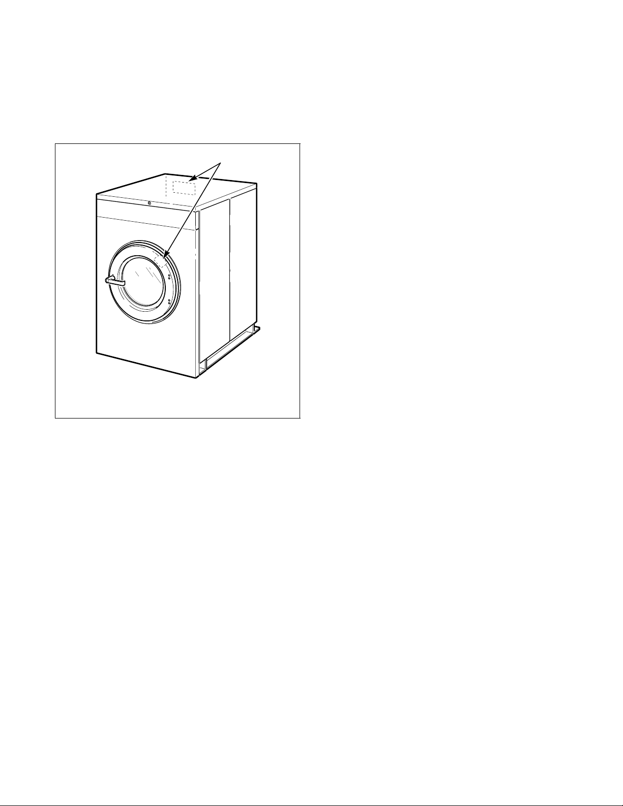
Nameplate Location
The nameplate is located at the rear of the machine and
inside door. Always provide the machine’s serial
number and model number when ordering parts or
when seeking technical assistance.
1
Replacement Parts
If literature or replacement parts are required, contact
the source from whom the machine was purchased
or contact Alliance Laundry Systems LLC at
(920) 748-3950 for the name and address of the
nearest authorized parts distributor.
Customer Service
For technical assistance, call any of the following
numbers:
(920) 748-3121
Ripon, Wisconsin U.S.A.
1 Nameplate
CHM167R
F232139
© Copyright, Alliance Laundry Systems LLC – DO NOT COPY or TRANSMIT
3
Page 6

Safety Information
Precautionary statements (“DANGER,” “WARNING”
and “CAUTION”), followed by specific instructions,
are found in this manual and on machine decals. These
precautions are intended for the personal safety of the
operator, user, servicer and those maintaining the
machine.
DANGER
DANGER indicates the presence of a
hazard that will cause severe personal
injury, death, or substantial property
damage if the danger is ignored.
WARNING
WARNING indicates the presence of a
hazard that can cause severe personal
injury, death, or substantial property
damage if the warning is ignored.
CAUTION
CAUTION indicates the presence of a
hazard that will or can cause minor
personal injury or property damage if the
caution is ignored.
Additional precautionary statements (“IMPORTANT”
and “NOTE”) are followed by specific instructions.
IMPORTANT: The word “IMPORTANT” is used
to inform the reader of specific procedures where
minor machine damage will occur if the procedure
is not followed.
NOTE: The word “NOTE” is used to communicate
installation, operation, maintenance or servicing
information that is important but not hazard
related.
Important Safety Instructions
WARNING
To reduce the risk of fire, electric shock,
serious injury or death to persons when
using your washer, follow these basic
precautions:
W023
1. Read all instructions before using the washer.
2. Refer to the GROUNDING INSTRUCTIONS in
the INSTALLATION Manual for the proper
grounding of the washer.
3. Do not wash textiles that have been previously
cleaned in, washed in, soaked in, or spotted with
gasoline, kerosene, waxes, cooking oils, drycleaning solvents, or other flammable or
explosive substances as they give off vapors that
could ignite or explode.
4. Do not add gasoline, dry-cleaning solvents, or
other flammable or explosive substances to the
wash water. These substances give off vapors that
could ignite or explode.
5. Under certain conditions, hydrogen gas may be
produced in a hot water system that has not been
used for two weeks or more. HYDROGEN GAS
IS EXPLOSIVE. If the hot water system has not
been used for such a period, before using a
washing machine or combination washer-dryer,
turn on all hot water faucets and let the water
flow from each for several minutes. This will
release any accumulated hydrogen gas. The gas is
flammable; do not smoke or use an open flame
during this time.
6. Do not allow children to play on or in the washer.
Close supervision of children is necessary when
the washer is used near children. This is a safety
rule for all appliances.
7. Before the washer is removed from service or
discarded, remove the door to the washing
compartment.
8. Do not reach into the washer if the wash drum is
moving.
4
© Copyright, Alliance Laundry Systems LLC – DO NOT COPY or TRANSMIT
F232139
Page 7

Safety Information
9. Do not install or store the washer where it will be
exposed to water and/or weather.
10. Do not tamper with the controls.
11. Do not repair or replace any part of the washer, or
attempt any servicing unless specifically
recommended in the user-maintenance
instructions or in published user-repair
instructions that the user understands and has the
skills to carry out.
12. To reduce the risk of an electric shock or fire, DO
NOT use an extension cord or an adapter to
connect the washer to the electrical power source.
13. Use washer only for its intended purpose,
washing textiles.
14. Never wash machine parts or automotive parts in
the machine. This could result in serious damage
to the basket.
15. ALWAYS disconnect the washer from electrical
supply before attempting any service. Disconnect
the power cord by grasping the plug, not the cord.
16. Install the washer according to the
INSTALLATION INSTRUCTIONS. All
connections for water, drain, electrical power and
grounding must comply with local codes and be
made by licensed personnel when required.
17. To reduce the risk of fire, textiles which have
traces of any flammable substances such as
vegetable oil, cooking oil, machine oil,
flammable chemicals, thinner, etc. or anything
containing wax or chemicals such as in mops and
cleaning cloths, must not be put into the washer.
These flammable substances may cause the
fabric to catch on fire by itself.
18. Do not use fabric softeners or products to
eliminate static unless recommended by the
manufacturer of the fabric softener or product.
19. Keep washer in good condition. Bumping or
dropping the washer can damage safety features.
If this occurs, have washer checked by a qualified
service person.
20. If the supply cord is damaged, it must be replaced
by a special cord or assembly available from the
manufacturer or its service agent.
21. Be sure water connections have a shut-off valve
and that fill hose connections are tight. CLOSE
the shut-off valves at the end of each wash day.
22. Loading door MUST BE CLOSED any time the
washer is to fill, tumble or spin. DO NOT bypass
the loading door switch by permitting the washer
to operate with the loading door open.
23. Always read and follow manufacturer’s
instructions on packages of laundry and cleaning
aids. Heed all warnings or precautions. To reduce
the risk of poisoning or chemical burns, keep
them out of the reach of children at all times
(preferably in a locked cabinet).
24. Always follow the fabric care instructions
supplied by the textile manufacturer.
25. Never operate the washer with any guards and/or
panels removed.
26. DO NOT operate the washer with missing or
broken parts.
27. DO NOT bypass any safety devices.
28. Failure to install, maintain and/or operate this
washer according to the manufacturer’s
instructions may result in conditions which can
produce bodily injury and/or property damage.
NOTE: The WARNINGS and IMPORTANT
SAFETY INSTRUCTIONS appearing in this
manual are not meant to cover all possible
conditions and situations that may occur. Common
sense, caution and care must be exercised when
installing, maintaining or operating the washer.
Any problems or conditions not understood should be
reported to the dealer, distributor, service agent or the
manufacturer.
F232139
© Copyright, Alliance Laundry Systems LLC – DO NOT COPY or TRANSMIT
5
Page 8

Safety Information
WARNING
This machine must be installed, adjusted,
and serviced by qualified electrical
maintenance personnel familiar with the
construction and operation of this type of
machinery. They must also be familiar
with the potential hazards involved.
Failure to observe this warning may result
in personal injury and/or equipment
damage, and may void the warranty.
SW004
IMPORTANT: Ensure that the recommended
clearances for inspection and maintenance
are provided. Never allow the inspection and
maintenance space to be blocked.
WARNING
Install the machine on a level floor of
sufficient strength. Failure to do so may
result in conditions which can produce
serious injury, death and/or property
damage.
W703
CAUTION
Be careful around the open door,
particularly when loading from a level
below the door. Impact with door edges
can cause personal injury.
SW025
WARNING
Never touch internal or external steam
pipes, connections, or components.
These surfaces can be extremely hot and
will cause severe burns. The steam must
be turned off and the pipe, connections,
and components allowed to cool before
the pipe can be touched.
SW014
Safety Decals
Safety decals appear at crucial locations on the
machine. Failure to maintain legible safety decals
could result in injury to the operator or service
technician.
To provide personal safety and keep the machine in
proper working order, follow all maintenance and
safety procedures presented in this manual. If
questions regarding safety arise, contact the
manufacturer immediately.
Use manufacturer-authorized spare parts to avoid
safety hazards.
6
© Copyright, Alliance Laundry Systems LLC – DO NOT COPY or TRANSMIT
F232139
Page 9

Safety Information
Operator Safety
WARNING
NEVER insert hands or objects into
basket until it has completely stopped.
Doing so could result in serious injury.
SW012
To ensure the safety of machine operators, the
following maintenance checks must be performed
daily:
1. Prior to operating the machine, verify that all
warning signs are present and legible. Missing or
illegible signs must be replaced immediately.
Make certain that spares are available.
2. Check door interlock before starting operation of
the machine:
a. Attempt to start the machine with the door
open. The machine should not start with the
door open.
b. Close the door without locking it and attempt
to start the machine. The machine should not
start with the door unlocked.
Do not bypass any safety devices in the machine.
WARNING
Never operate the machine with a
bypassed or disconnected balance
system. Operating the machine with
severe out-of-balance loads could result
in personal injury and serious equipment
damage.
SW039
c. Close and lock the door and start a cycle.
Attempt to open the door while the cycle is in
progress. The door should not open.
If the door lock and interlock are not functioning
properly, call a service technician.
3. Do not attempt to operate the machine if any of
the following conditions are present:
a. The door does not remain securely locked
during the entire cycle.
b. Excessively high water level is evident.
c. Machine is not connected to a properly
grounded circuit.
F232139
© Copyright, Alliance Laundry Systems LLC – DO NOT COPY or TRANSMIT
7
Page 10
Programming
S-Series Microcomputers
The computer board is inside the control module. Near
the center of the board is a small toggle switch: this is
the RUN/PROGRAM mode switch.
WARNING
Dangerous voltages are present in the
electrical control box(es) and at the motor
terminals. Only qualified personnel
familiar with electrical test procedures,
test equipment, and safety precautions
should attempt adjustments and
troubleshooting. Disconnect power from
the machine before removing the control
box cover, and before attempting any
service procedures.
SW005
The RUN/PROGRAM switch is normally in the up
(RUN mode) position. To enter PROGRAM mode, flip
the switch to the down position. The display will now
show the current temperature in the sump.
Since the keypad operates in a slightly different
fashion when in PROGRAM mode, pay careful
attention to the programming instructions provided in
this manual.
Key Functions In Programming Mode
Up – The Up key is used to increase cycle numbers
(1 through 30) and other numerical values such as
times or temperatures (when creating wash formulas).
Down – The Down key is used to decrease cycle
numbers (1 through 30) and other numerical values
such as times or temperatures (when creating wash
formulas).
Start – The Start key acts as an enter key in program
mode. Use this key to enter data and move to the next
function in the cycle.
Cycle Count
To display the current cycle count, press the Start key
while the display is showing the temperature in the
sump. The display will show a 2-digit number
indicating how many cycles have been run to
completion (cycles which were stopped in progress are
not counted). Press the Start key to return to
PROGRAM mode without resetting the count. Press
the Up or Down key to reset the count to zero and
return to PROGRAM mode.
Cycle Programming
To edit an existing cycle or create a new cycle, press
the Up key while the display is showing the
temperature in the sump. The display will show
“CY01.” Press the Up or Down key until the desired
cycle number is displayed. Press the Start key to begin
editing the selected cycle.
All cycle programs (“CY01” – “CY30”) can be
customized within a preset program structure. Each
cycle program consists of eight program segments.
Refer to Tab l e 1.
Cycle Program Segments
Segment Display Segment Display
Prewash PrE Fill 3 FIL3
Wash UASH Fill 4 FIL4
Fill 1 FIL1 Fill 5 FIL5
Fill 2 FIL2 Fill 6 FIL6
Table 1
When modifying a cycle, a time must be entered for
each segment. To skip a segment or spin, set the time
to “00” and press the Start key.
Stop – The Stop key saves all data and terminates the
programming procedure. If it is the first key pressed in
PROGRAM mode, the computer enters SETUP mode.
The Stop key can be pressed again to exit SETUP
mode and return to PROGRAM mode.
8
© Copyright, Alliance Laundry Systems LLC – DO NOT COPY or TRANSMIT
F232139
Page 11

Programming
Entering Program Mode
1. Unlock and raise top cover.
2. Remove control module cover.
3. Locate the Run/Program Mode switch near
center of computer board inside control module.
Refer to Figure 1.
2
1 Run/Program Mode Switch
2 Computer Board
Programming a Cycle
1. Press Up (arrow) key until computer display
shows segment to be edited. Press Start (#) key.
2. Use Up or Down (arrow) key to select desired
segment time. Refer to Tab l e 2. Set value to zero
to skip segment. Press Start (#) key.
1
PreWash 1 minute 30 minutes
Wash 2 minutes 20 minutes
Fill 1 2 minutes 15 minutes
Fill 2 2 minutes 15 minutes
Fill 3 2 minutes 15 minutes
Fill 4 2 minutes 15 minutes
Fill 5 2 minutes 15 minutes
B152R
Fill 6 2 minutes 15 minutes
Intermediate Spin 30 seconds 120 seconds
Time and Temperature Parameters
Segment Minimum Maximum
Figure 1
4. Flip switch to down position to enter Program
Mode. Display will show current temperature of
sump.
Programming Setup Mode
NOTE: Selection of degrees Fahrenheit or Celsius
is only option for setup.
1. Press Stop (*) key to enter Setup Mode while
display is showing temperature in sump.
2. Use Up or Down (arrow) key to change selected
option. Press Start (#) key to accept selected
option, either “FAr” or “CEL”.
3. Press Stop (*) key to exit Setup Mode.
Final Spin 1 minute 10 minutes
Temperature 75°F (25°C) 200°F (93°C)
Table 2
NOTE: Spin times in cycle segments 1 – 8 are
entered in seconds (30 to 120), and time for final
spin in segment 11 is entered in minutes (1 to 10).
NOTE: The computer does not count down the
remaining cycle time during fills, drains, or prior to
first achieving the programmed heat temperature
when heating. The computer resumes counting
down cycle time once the programmed fill level is
reached, when the machine has drained, and after a
programmed heat temperature is reached.
WARNING
To avoid personal injury, recommended
inlet water temperature should be no
higher than 125° Fahrenheit (51° Celsius).
W709
F232139
© Copyright, Alliance Laundry Systems LLC – DO NOT COPY or TRANSMIT
9
Page 12

Programming
3. Use Up or Down (arrow) key to select fill
temperature: cold (CFIL), hot (HFIL) or
warm (bFIL). Press Start (#) key.
4. Use Up or Down (arrow) key to select fill level:
low level (LOLE) or high level (HILE). Press
Start (#) key.
Supply Dispenser
Compartments
2
1
3
5. Use Up or Down (arrow) key to select supply
option. Refer to Tab le 3. Press Start (#) key.
Supply Options
Display Supply
SUP0 No Supply
SUP1 Supply 1
SUP2 Supply 2
SUP3 Supply 3
SUP4 Supply 4
SUP5 Supply 1 and 2
SUP6 Supply 2 and 3
SUP7 Supply 3 and 4
Table 3
The Supply Dispenser Compartment functions as
follows: Supply compartment 1 flushes with each fill.
Supply compartment 2 flushes when the program calls
for supply 2 during a fill. Supply compartment 3
flushes when the program calls for supply 3 during a
fill.
The Chemical Injection Supply Nozzles located in
their respective supply compartments function as
follows: Chemical supply nozzle 1 empties into
compartment 1, chemical supply nozzle 2 and 4 empty
into compartment 2, and chemical supply nozzle 3
empties into compartment 3. Refer to Figure 2.
3
4
B009RE3A
B009RE3A
Chemical Injection
Supply Dispenser Compartments
1 Detergent
2 Bleach
3 Softner
Chemical Injection Supply Nozzles
1 Detergent
2/4 Bleach
3 Softner
Figure 2
1
2
Supply Nozzles
NOTE: Compartment 2 does not flush when supply
4 is called for in a program.
6. If machine is equipped with auxiliary heating
system, use Up or Down (arrow) key to select
desired segment temperature. Set value to zero to
disable auxiliary heat for this segment. Press
Start (#) key.
NOTE: Do not program heat steps for machines
not equipped with auxiliary heat. The machine will
pause for 30 minutes during any step in which the
fill water temperature does not already equal or
exceed the programmed value of the heat step.
10
7. Use Up or Down (arrow) key to select spin time.
Set value to zero to skip spin step. Press Start (#)
key. Display will now show the identifier for next
program segment.
8. Press the Stop (#) key to complete cycle
programming procedure.
Refer to the Cycle Charts section for detailed
description of cycles.
© Copyright, Alliance Laundry Systems LLC – DO NOT COPY or TRANSMIT
F232139
Page 13

Programming
Armstrong S-Series Microcomputers
NOTE: This section deals with machines that have
the Armstrong S-series microcomputer only. When
power is supplied to the machine, an Armstrong
microcomputer will read “S 14”.
Programming Mode
In the program mode, where the operator creates and
changes cycle programs, some display messages have
been changed. Refer to Ta b le 3 .
Previous software display
PrE
(Prewash step)
PrEU
(Prewash, no “sluice” selected)
SLUC
(Step contained a “sluice”)
UASH
(Wash step)
FIL1 FIL3
FIL2 FIL4
FIL3 FIL5
drin
(“dilution rinse” no sluice)
FIL4 FIL6
New software
display
FIL1
FILL
ovEr
(Overflow fill)*
FIL2
FILL
Automatic Cool-Down
NOTE: Can be disabled.
The automatic cool-down feature prevents the drain
from opening until the temperature of the water in the
°
sump falls below 140
F (60°C).
This feature becomes active during a drain step, if the
step is programmed for “drAI” when the temperature
is above the threshold temperature. During the
cool-down, the COLD fill valve is energized, the drain
remains closed and the machine continues to agitate as
it did prior to the cool-down. When the temperature
°
falls below 140
F (60°C), the COLD fill valve turns
off and the drain step proceeds as normal.
Enabling/Disabling Cool-Down
NOTE: Factory default is disabled.
To enable or disable the cool-down feature, first enter
Program Mode, refer to page 7, then proceed as
follows:
1. After entering Program Mode display shows
temperature. Press Stop (*) key.
2. Display shows “
3. Display shows “HEAt”. Press Start (#) key.
4. Display shows “CooL” if cool-down is enabled
or “noCL” if disabled. To change this, press Up
or Down (arrow) key.
5. Press Start (#) key to save and return to Program
Mode.
°
CEL”. Press Start (#) key.
FIL5 FIL7
FIL6 FIL8
Table 4
*NOTE: Because the COLD water valve might
remain energized for some time, it is necessary to
ensure that the machine has a suitable overflow
connection.
F232139
© Copyright, Alliance Laundry Systems LLC – DO NOT COPY or TRANSMIT
11
Page 14

Programming
Cycle Segment Charts
Segment 1 (Prewash)
Display
PrE
00 or 02 to 30 Select segment time: 02 to 30 minutes (00 to skip segment)
HFIL, CFIL, or bFIL Select “HFIL” (hot fill), “CFIL” (cold fill), or “bFIL” (warm fill)
LOLE or HILE Select fill level: “LOLE” (low), or “HILE” (high) water level
SUP0–SUP7 Select supply 0 – 7 (0 for no supply)
00°F, 75°F–200°F
00°C, 25°C–93°C
SPIn (flashed for one second)
tINE (flashed for one second)
00 or 30 to 120 Select time for spin: 30 to 120 seconds (00 for no spin)
Display
UASH
00 or 02 to 20 Select segment time: 02 to 20 minutes (00 to skip segment)
Use the Up or Down key to change. Press the Start key to enter or advance.
Select temperature: 75 to 200°F or 25 to 93°C (00 for no heat)
Segment 2 (Wash)
Use the Up or Down key to change. Press the Start key to enter or advance.
Instructions
Instructions
HFIL, CFIL, or bFIL Select “HFIL” (hot fill), “CFIL” (cold fill), or “bFIL” (warm fill)
LOLE or HILE Select fill level: “LOLE” (low), or “HILE” (high) water level
SUP0–SUP7 Select supply 0–7 (0 for no supply)
00°F, 75°F–200°F
00°C, 25°C–93°C
SPIn (flashed for one second)
tINE (flashed for one second)
00 or 30 to 120 Select time for spin: 30 to 120 seconds (00 for no spin)
Select temperature: 75 to 200°F or 25 to 93°C (00 for no heat)
12
© Copyright, Alliance Laundry Systems LLC – DO NOT COPY or TRANSMIT
F232139
Page 15

Cycle Segment Charts (Continued)
Segments 3 – 7 (Fills 1 – 5)
Programming
Display
FIL1, FIL2, FIL3, FIL4, or FIL5
00 or 02 to 15 Select segment time: 02 to 15 minutes (00 to skip segment)
HFIL, CFIL, or bFIL Select “HFIL” (hot fill), “CFIL” (cold fill), or “bFIL” (warm fill)
LOLE or HILE Select fill level: “LOLE” (low), or “HILE” (high) water level
SUP0–SUP7 Select supply 0 – 7 (0 for no supply)
00°F, 75°F–200°F
00°C, 25°C–93°C
SPIn (flashed for one second)
tINE (flashed for one second)
00 or 30 to 120 Select time for spin: 30 to 120 seconds (00 for no spin)
Display
FIL6
00 or 02 to 15 Select segment time: 02 to 15 minutes (00 to skip segment)
Use the Up or Down key to change. Press the Start key to enter or advance.
Select temperature: 75 to 200°F or 25 to 93°C (00 for no heat)
Segment 8 (Fill 6)
Use the Up or Down key to change. Press the Start key to enter or advance.
Instructions
Instructions
HFIL, CFIL, or bFIL Select “HFIL” (hot fill), “CFIL” (cold fill), or “bFIL” (warm fill)
LOLE or HILE Select fill level: “LOLE” (low), or “HILE” (high) water level
SUP0–SUP7 Select supply 0 – 7 (0 for no supply)
00°F, 75°F–200°F
00°C, 25°C–93°C
SPIn (flashed for one second)
tINE (flashed for one second)
00 or 01 to 10 Select time for spin: 1 to 10 minutes (00 for no spin)
Select temperature: 75 to 200°F or 25 to 93°C (00 for no heat)
F232139
© Copyright, Alliance Laundry Systems LLC – DO NOT COPY or TRANSMIT
13
Page 16

Programming
Cycle Charts
S-Series Microcomputers Standard Cycles
Cycle
Program
PreWash
Time (Min.)000222
Water - - - - - - - - - Cold Hot Cold
Level - - - - - - - - - High High High
Supply - - - - - - - - - 0 0 0
Temp (F) - - - - - - - - - 0 0 0
Spin (Sec.) - - - - - - - - - 0 0 0
Wash
Time (Min.)667755
Water Hot Warm Hot Warm Hot Warm
Level Low Low Low Low Low Low
Supply 511111
Temp (F)000000
Spin (Sec.) 40 40 60 60 60 60
Fill 1
Time (Min.)005255
Water - - - - - - Hot Warm Hot Warm
Level - - - - - - Low High Low Low
Supply- - -- - -2011
Temp (F)- - -- - -0000
Spin (Sec.) - - - - - - 60 40 0 60
Fill 2
Time (Min.)002063
Water - - - - - - Warm - - - Hot Warm
Level - - - - - - High - - - Low High
Supply - - - - - - 0 - - - 2 0
Temp (F) - - - - - - 0 - - - 0 0
Spin (Sec.) - - - - - - 40 - - - 60 0
Fill 3
Time (Min.)000020
Water - - -- - -- - -- - -Hot- - -
Level - - -- - -- - -- - -High- - -
Supply - - -- - -- - -- - - 0 - - -
Temp (F) - - - - - - - - - - - - 0 - - -
Spin (Sec.) - - - - - - - - - - - - 60 - - -
Fill 4
Time (Min.)000020
Water - - -- - -- - -- - -Hot- - -
Level - - -- - -- - -- - -High- - -
Supply - - -- - -- - -- - - 0 - - -
Temp (F) - - - - - - - - - - - - 0 - - -
Spin (Sec.) - - - - - - - - - - - - 0 - - -
1
Light Soil
Whites
2
Light Soil
Colors
3
Medium Soil
Whites
4
Medium Soil
Colors
5
Heavy Soil
Whites
6
Heavy Soil
Colors
14
© Copyright, Alliance Laundry Systems LLC – DO NOT COPY or TRANSMIT
F232139
Page 17

Programming
S-Series Microcomputers Standard Cycles (Continued)
Cycle
Program
Fill 5
Time (Min.)332233
Water Warm Warm Warm Warm Warm Warm
Level High High High High High High
Supply 000000
Temp (F)000000
Spin (Sec.)000000
Fill 6
Time (Min.)333333
Water Warm Warm Warm Warm Warm Warm
Level High High High High High High
Supply 333333
Temp (F)000000
Spin (Min.)545454
1
Light Soil
Whites
2
Light Soil
Colors
3
Medium Soil
Whites
4
Medium Soil
Colors
5
Heavy Soil
Whites
6
Heavy Soil
Colors
F232139
© Copyright, Alliance Laundry Systems LLC – DO NOT COPY or TRANSMIT
15
Page 18

Programming
S-Series Microcomputers Standard Cycles (Continued)
Cycle
Program
PreWash
Time (Min.)223306
Water Cold Cold Warm Warm - - - Warm
Level High High High High - - - Low
Supply 0 0 1 0 - - - 1
Temp (F) 0 0 0 0 - - - 0
Spin (Sec.)0000- - -0
Wash
Time (Min.)268605
Water Warm Cold Hot Hot - - - Hot
Level High Low Low Low - - - Low
Supply 0 1 5 1 - - - 1
Temp (F) 0 0 0 0 - - - 0
Spin (Sec.)060060- - -60
Fill 1
Time (Min.)626503
Water Warm Cold Hot Hot - - - Hot
Level Low High High Low - - - High
Supply 1 0 2 1 - - - 0
Temp (F) 0 0 0 0 - - - 0
Spin (Sec.) 30 0 60 60 - - - 60
Fill 2
Time (Min.)303600
Water Warm - - - Warm Hot - - - - - -
Level High - - - High Low - - - - - -
Supply 0 - - - 0 2 - - - - - -
Temp (F) 0 - - - 0 0 - - - - - -
Spin (Sec.) 0 - - - 60 60 - - - - - -
Fill 3
Time (Min.)200300
Water Warm- - -- - -Hot- - -- - -
Level High - - - - - - High - - - - - -
Supply 0 - - - - - - 0 - - - - - -
Temp (F) 0 - - - - - - 0 - - - - - -
Spin (Sec.) 0 - - - - - - 0 - - - - - -
Fill 4
Time (Min.)000000
Water - - -- - -- - -- - -- - -- - -
Level - - -- - -- - -- - -- - -- - -
Supply - - -- - -- - -- - -- - -- - -
Temp (F) - - -- - -- - -- - -- - -- - -
Spin (Sec.)- - -- - -- - -- - -- - -- - -
7
Permanent
Press Visa
8
Gentle Delicate
Wool
9
ReWash
Destaining
10
Heavy
Soil
11
Rinse
Spin
12
Personals
Starch
16
© Copyright, Alliance Laundry Systems LLC – DO NOT COPY or TRANSMIT
F232139
Page 19

Programming
S-Series Microcomputers Standard Cycles (Continued)
Cycle
Program
Fill 5
Time (Min.)303302
Water Cold - - - Warm Warm - - - Warm
Level High - - - High High - - - High
Supply 3- - -0 0- - -0
Temp (F) 0 - - - 0 0 - - - 0
Spin (Sec.) 40 - - - 0 0 - - - 0
Fill 6
Time (Min.)033324
Water - - - Cold Warm Warm Warm Warm
Level - - - High High High Low High
Supply- - -33304
Temp (F)- - -00000
Spin (Min.)- - -35524
7
Permanent
Press Visa
8
Gentle Delicate
Wool
9
ReWash
Destaining
10
Heavy
Soil
11
Rinse
Spin
12
Personals
Starch
F232139
© Copyright, Alliance Laundry Systems LLC – DO NOT COPY or TRANSMIT
17
Page 20

Programming
S-Series Microcomputers Cycles
Cycle
Program
PreWash
Time (Min.) 0 0 0
Water - - - - - - - - -
Level - - - - - - - - -
Supply - - - - - - - - -
Temp (F) - - - - - - - - -
Spin (Sec.) - - - - - - - - -
Wash
Time (Min.) 3 3 0
Wat e r Wa r m War m - - -
Level High High - - -
Supply 1 1 - - -
Temp (F) 0 80 - - -
Spin (Sec.) 0 0 - - -
Fill 1
Time (Min.) 0 0 0
Water - - - - - - - - -
Level - - - - - - - - -
Supply - - - - - - - - -
Temp (F) - - - - - - - - -
Spin (Sec.) - - - - - - - - -
Fill 2
Time (Min.) 0 0 0
Water - - - - - - - - -
Level - - - - - - - - -
Supply - - - - - - - - -
Temp (F) - - - - - - - - -
Spin (Sec.) - - - - - - - - -
Fill 3
Time (Min.) 0 0 0
Water - - - - - - - - -
Level - - - - - - - - -
Supply - - - - - - - - -
Temp (F) - - - - - - - - -
Spin (Sec.) - - - - - - - - -
Fill 4
Time (Min.) 0 0 0
Water - - - - - - - - -
Level - - - - - - - - -
Supply - - - - - - - - -
Temp (F) - - - - - - - - -
Spin (Sec.) - - - - - - - - -
13
Test Cycle 114Test Cycle 2
15 16 17 18
18
© Copyright, Alliance Laundry Systems LLC – DO NOT COPY or TRANSMIT
F232139
Page 21

Cycle
Program
Fill 5
Time (Min.) 2 2
Water Cold Cold
Level Low Low
Supply 2 2
Tem p (F) 0 0
Spin (Sec.) 0 0
Fill 6
Time (Min.) 2 2
Wate r Ho t H ot
Level Low Low
Supply 3 3
Tem p (F) 0 0
Spin (Sec.) 3 3
13
Test Cycle 114Test Cycle 2
Programming
S-Series Microcomputers Cycles (Continued)
15 16 17 18
F232139
© Copyright, Alliance Laundry Systems LLC – DO NOT COPY or TRANSMIT
19
Page 22

Programming
Cycle
Program
PreWash
Time (Min.)
Wat er
Level
Supply
Tem p (F)
Spin (Sec.)
Wash
Time (Min.)
Wat er
Level
Supply
Tem p (F)
Spin (Sec.)
Fill 1
Time (Min.)
Wat er
Level
Supply
Tem p (F)
Spin (Sec.)
Fill 2
Time (Min.)
Wat er
Level
Supply
Tem p (F)
Spin (Sec.)
Fill 3
Time (Min.)
Wat er
Level
Supply
Tem p (F)
Spin (Sec.)
Fill 4
Time (Min.)
Wat er
Level
Supply
Tem p (F)
Spin (Sec.)
S-Series Microcomputers Blank Cycles
19 20 21 22 23 24
20
© Copyright, Alliance Laundry Systems LLC – DO NOT COPY or TRANSMIT
F232139
Page 23

Fill 5
Fill 6
Cycle
Program
Time (Min.)
Wate r
Level
Supply
Tem p (F)
Spin (Sec.)
Time (Min.)
Wate r
Level
Supply
Tem p (F)
Spin (Sec.)
Programming
S-Series Microcomputers Blank Cycles (Continued)
19 20 21 22 23 24
F232139
© Copyright, Alliance Laundry Systems LLC – DO NOT COPY or TRANSMIT
21
Page 24

Programming
Cycle
Program
PreWash
Time (Min.)
Wat er
Level
Supply
Tem p (F)
Spin (Sec.)
Wash
Time (Min.)
Wat er
Level
Supply
Tem p (F)
Spin (Sec.)
Fill 1
Time (Min.)
Wat er
Level
Supply
Tem p (F)
Spin (Sec.)
Fill 2
Time (Min.)
Wat er
Level
Supply
Tem p (F)
Spin (Sec.)
Fill 3
Time (Min.)
Wat er
Level
Supply
Tem p (F)
Spin (Sec.)
Fill 4
Time (Min.)
Wat er
Level
Supply
Tem p (F)
Spin (Sec.)
S-Series Microcomputers Blank Cycles (Continued)
25 26 27 28 29 30
22
© Copyright, Alliance Laundry Systems LLC – DO NOT COPY or TRANSMIT
F232139
Page 25

Fill 5
Fill 6
Cycle
Program
Time (Min.)
Wate r
Level
Supply
Tem p (F)
Spin (Sec.)
Time (Min.)
Wate r
Level
Supply
Tem p (F)
Spin (Sec.)
Programming
S-Series Microcomputers Blank Cycles (Continued)
25 26 27 28 29 30
F232139
© Copyright, Alliance Laundry Systems LLC – DO NOT COPY or TRANSMIT
23
Page 26

Programming
Armstrong S-Series Microcomp uters Cycles
Cycle
Program1Very Hot
90°C
Fill 1
Fill/over Fill Fill Fill Fill Fill Fill
Time (Min.)022000 20
Water - - - Cold Cold - - - - - - - - - Cold - - -
Level - - - High High - - - - - - - - - High - - -
Supply - - - S0 S0 - - - - - - - - - S0 - - -
Temp (C) - - - 0 0 - - - - - - - - - 0 - - -
Drain - - - Drai Drai - - - - - - - - - Drai - - -
Spin (Sec.) - - - 0 0 - - - - - - - - - 0 - - -
Fill 2
Time (Min.)022000 20
Water - - - Cold Cold - - - - - - - - - Cold - - -
Level - - - High High - - - - - - - - - High - - -
Supply - - - S0 S0 - - - - - - - - - S0 - - -
Temp (C) - - - 0 0 - - - - - - - - - 0 - - -
Drain - - - Drai Drai - - - - - - - - - Drai - - -
Spin (Sec.) - - - 0 0 - - - - - - - - - 0 - - -
Fill 3
Time (Min.)333440 25
Water Hot Hot Both Cold Cold - - - Cold Cold
Level Low Low Low Low Low - - - Low Low
Supply S1 S1 S1
Temp (C)60606040 0- - - 4040
Drain Drai Drai Drai Drai Drai - - - Drai Drai
Spin (Sec.)00000- - - 030
Fill 4
Time (Min.)444450 30
Water Hot Hot Hot Both Cold - - - Both - - -
Level Low Low Low Low Low - - - Low - - -
SupplyS2S2S2S2S2- - - S2- - -
Temp (C)9085716040- - - 60- - -
Drain No Dr No Dr No Dr Drai Drai - - - Drai - - -
Spin (Sec.) 0 0 0 30 30 - - - 30 - - -
Fill 5
Fill/over Fill Fill Fill Fill Fill Fill Fill Fill
Time (Min.)222000 00
Water Cold Cold Cold - - - - - - - - - - - - - - -
Level High High High - - - - - - - - - - - - - - -
Supply S0 S0 S0 - - - - - - - - - - - - - - -
Temp (C) 0 0 0 - - - - - - - - - - - - - - -
Drain Drai Drai Drai - - - - - - - - - - - - - - -
Spin (Sec.) 30 30 30 - - - - - - - - - - - - - - -
2
Hot Medical
85°C
Sluice
3
Medical
71°C
Sluice
4
Warm
60°C
S1 S1
5
Cool
40°C
6
Rinse
and
Spin
- - -
7-10 11
Warm
Gentle
60°C
Sluice
Fill Fill
C
U
S
T
O
M
E
R
R
E
Q
U
E
S
T
E
D
P
R
O
G
R
A
M
S
S1 S1
12
Cool Gentle
40°C
24
© Copyright, Alliance Laundry Systems LLC – DO NOT COPY or TRANSMIT
F232139
Page 27

Programming
Armstrong S-Series Microcomputers Cycles (Continued)
Cycle
Program1Very Hot
90°C
Fill 6
Time (Min.)222220
Water Both Both Both Both Cold - - - Both - - -
LevelHighHighHighHighHigh - - - High - - -
SupplyS0S0S0S0S0- - - S0- - -
Temp (C)00000- - - 0- - -
Drain Drai Drai Drai Drai Drai - - - Drai - - -
Spin (Sec.)00000- - - 0- - -
Fill 7
Time (Min.)222222 22
WaterColdColdColdColdColdBoth ColdCold
LevelHighHighHighHighHighHigh HighHigh
SupplyS0S0S0S0S0S0 S0S0
Temp (C)000000 00
Drain Drai Drai Drai Drai Drai Drai Drai Drai
Spin (Sec.)303030303030 3030
Fill 8
Time (Min.)333333 33
WaterColdColdColdColdColdCold ColdCold
LevelHighHighHighHighHighHigh HighHigh
SupplyS3S3S3S3S3S3 S3S3
Temp (C)000000 00
Drain Drai Drai Drai Drai Drai Drai Drai Drai
Spin (Sec.)666666 62
2
Hot Medical
85°C
Sluice
3
Medical
71°C
Sluice
4
Warm
60°C
5
Cool
40°C
6
Rinse
and
Spin
7-10 11
Warm
Gentle
60°C
Sluice
C
U
S
T
O
M
E
R
R
E
Q
U
E
S
T
E
D
P
R
O
G
R
A
M
S
12
Cool Gentle
40°C
20
F232139
© Copyright, Alliance Laundry Systems LLC – DO NOT COPY or TRANSMIT
25
 Loading...